Dancing L8
14
-
Upload
sovan-paul -
Category
Technology
-
view
349 -
download
0
Transcript of Dancing L8

DANCING LIGHT
SUBMITTED BY : XXXXXXXXROLL NO. : XXXXXXXXX
DIPERTMENT : XXXXXXXXXXXXXXX
INSTITUTE NAME : XXXXXXXXX
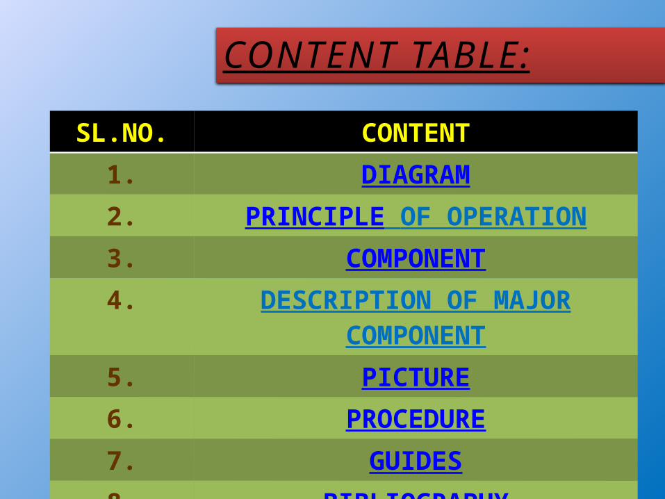
CONTENT TABLE:
SL.NO. CONTENT1. DIAGRAM2. PRINCIPLE OF OPERATION3. COMPONENT4. DESCRIPTION OF MAJOR
COMPONENT5. PICTURE6. PROCEDURE7. GUIDES8. BIBLIOGRAPHY
diagram
PRINCIPLE OF OPERATION:
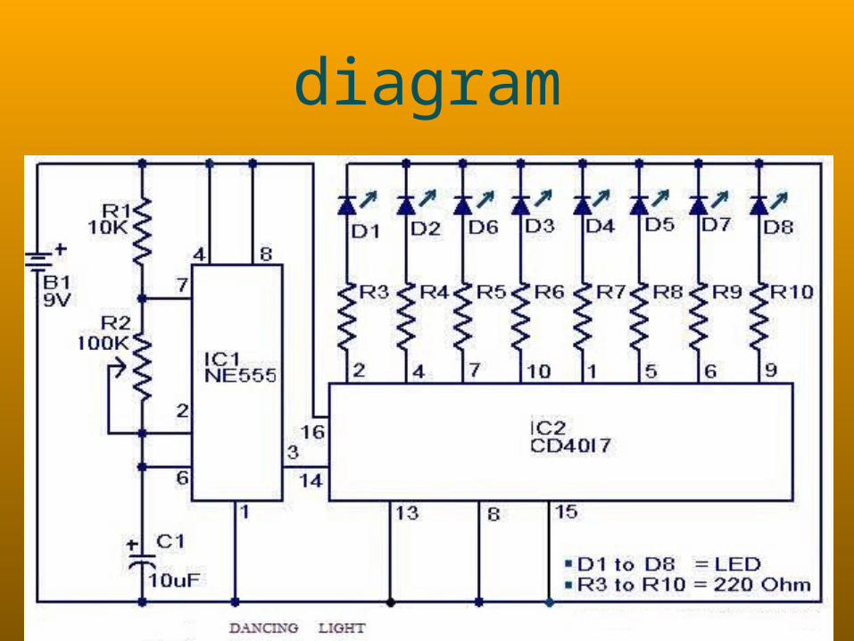
• Here is a simple dancing light circuit based on NE555 (IC1) & CD4017
(IC2) .• The IC1 is wired as an astable multivibrator to
provide the clock pulses for the CD4017.• For each clock pulse receiving at the clock input
(pin14) of IC CD4017, the outputs Q0 to Q9 (refer pin diagram of CD 4017) becomes high one by one
alternatively.• The LEDs connected to these pins glow in the same
fashion to give a dancing effect. The speed of the dancing LEDs depend on the frequency of the clock
pulses generated by the IC1.
COMPONENTS:IC: a) NE555 : 1 PC b) CD4017 : 1 PC
LED : 8PCS RESISTANCE:
a) 220 Ohm : 8 PCS b) 10 KOhm : 1 PC c) 100 Kohm : 1 PC
(VARIABLE)CAPACITOR: a) 10 UF : 1 PCBATTARY : 9V
Description of Major Component
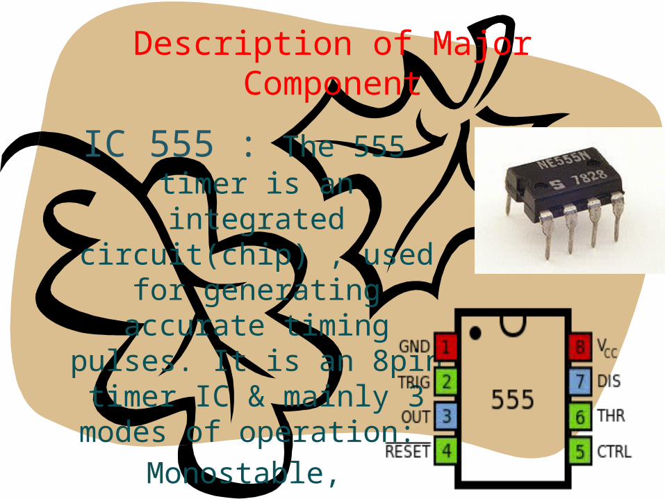
IC 555 : The 555 timer is an integrated circuit(chip) , used for generating accurate timing pulses. It is an 8pin timer IC & mainly 3 modes of operation:
Monostable, Astable &
Bistable.
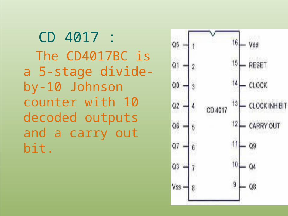
CD 4017 : The CD4017BC is a 5-
stage divide-by-10 Johnson counter with 10 decoded outputs and a carry out bit.
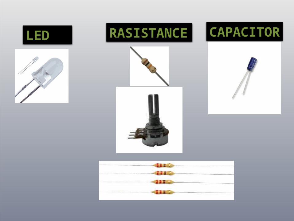
RASISTANCE
LED CAPACITOR
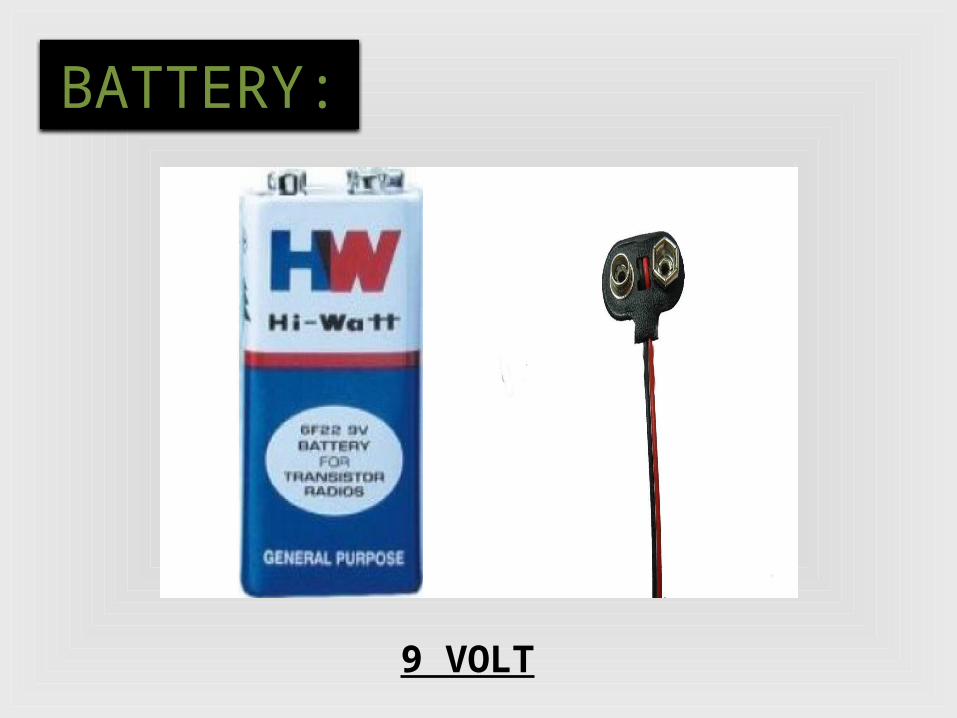
BATTERY:
9 VOLT
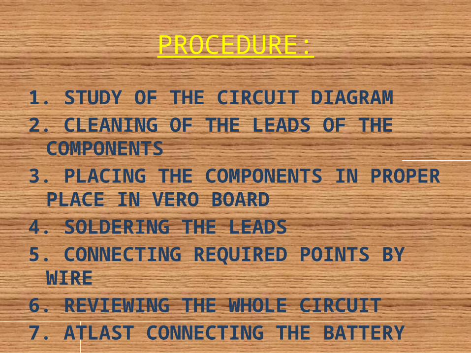
PROCEDURE:1. STUDY OF THE CIRCUIT DIAGRAM2. CLEANING OF THE LEADS OF THE
COMPONENTS3. PLACING THE COMPONENTS IN
PROPER PLACE IN VERO BOARD4. SOLDERING THE LEADS5. CONNECTING REQUIRED POINTS
BY WIRE6. REVIEWING THE WHOLE CIRCUIT7. ATLAST CONNECTING THE
BATTERY

GUIDES:
OUR RESPECTED TEACHERS:

BIBLIOGRAPHY:
INTERNETTEXT BOOK

THANK YOU