Dana 300 front out.2009.09.26 - JB Conversions · 1 Dana 300 32 Spline Front Output Shaft Upgrade...
15
1 D D a a n n a a 3 3 0 0 0 0 32 Spline Front Output Shaft Upgrade Manufactured by JB CONVERSIONS, INC. Phone: 337-625-2379 Installation Instructions Part No. 15-1103 Instruction Rev: 2009.09.26 Kit Components . 32 spline front output shaft . Tapered roller bearing #30207 (cup & cone) . Spacer ring . CV yoke # 2-4-5341 . 7/8" x 20 Lock nut - Chrysler #4167924 . Rubber star washer seal - Chrysler #4210973 . National oil seal #473454 IMPORTANT! PREASSEMBLY CHECK After the Dana 300 has been disassembled, refer to the photos A & B below to verify gear-to-shaft clearances. Place the original Dana gears (separately) onto the front output shaft as shown. Using a gap gauge, verify clearance between the grinded gear face and the shoulder on the shaft. Use a straight edge as shown.
-
Upload
vuongxuyen -
Category
Documents
-
view
220 -
download
0
Transcript of Dana 300 front out.2009.09.26 - JB Conversions · 1 Dana 300 32 Spline Front Output Shaft Upgrade...

1
DDaannaa 330000 32 Spline Front Output Shaft Upgrade
Manufactured by JB CONVERSIONS, INC.
Phone: 337-625-2379
Installation Instructions Part No. 15-1103 Instruction Rev: 2009.09.26 Kit Components . 32 spline front output shaft . Tapered roller bearing #30207 (cup & cone) . Spacer ring . CV yoke # 2-4-5341 . 7/8" x 20 Lock nut - Chrysler #4167924 . Rubber star washer seal - Chrysler #4210973 . National oil seal #473454 IMPORTANT!
PREASSEMBLY CHECK
After the Dana 300 has been disassembled, refer to the photos A & B below to verify gear-to-shaft clearances. Place the original Dana gears (separately) onto the front output shaft as shown. Using a gap gauge, verify clearance between the grinded gear face and the shoulder on the shaft. Use a straight edge as shown.

2
FIG: A
FIG: B

3
1) Drain the oil then remove the front output yoke and inspection cover (Fig.1).
FIG: 1
2) Remove the 5/16” retainer bolt and plate for the intermediate shaft. Using a brass or wood drift, remove the intermediate shaft as shown (Fig.2).
FIG: 2

4
3) Remove the idler gear from the case (Fig.3). Be aware of the needle bearings and 3 retaining rings in the center bore of the idler gear. Retain or replace during final assembly as desired.
FIG: 3
4) Using a 3/16” allen socket, remove the two shift fork set screws (Fig.4).
FIG: 4

5
5) Remove the aluminum bearing housing from the case. The shift rails will slide through the forks as the housing is removed. You may have to steady the forks with you fingers as the rods slide out (Fig.5).
FIG: 5
6) Remove the rear bearing retainer plate and shims from the case followed by the bearing cup (Fig.6).
FIG: 6

6
7) Using a 2-jaw puller, remove the helical gear and roller bearing as shown (Fig.7). Remove the slider as shown (Fig.8).
FIG: 7
FIG: 8
7
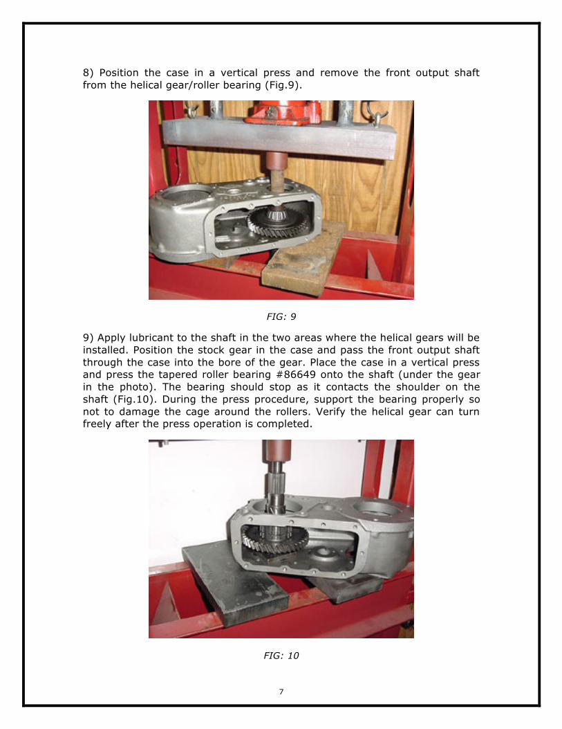
8) Position the case in a vertical press and remove the front output shaft from the helical gear/roller bearing (Fig.9).
FIG: 9
9) Apply lubricant to the shaft in the two areas where the helical gears will be installed. Position the stock gear in the case and pass the front output shaft through the case into the bore of the gear. Place the case in a vertical press and press the tapered roller bearing #86649 onto the shaft (under the gear in the photo). The bearing should stop as it contacts the shoulder on the shaft (Fig.10). During the press procedure, support the bearing properly so not to damage the cage around the rollers. Verify the helical gear can turn freely after the press operation is completed.
FIG: 10
8
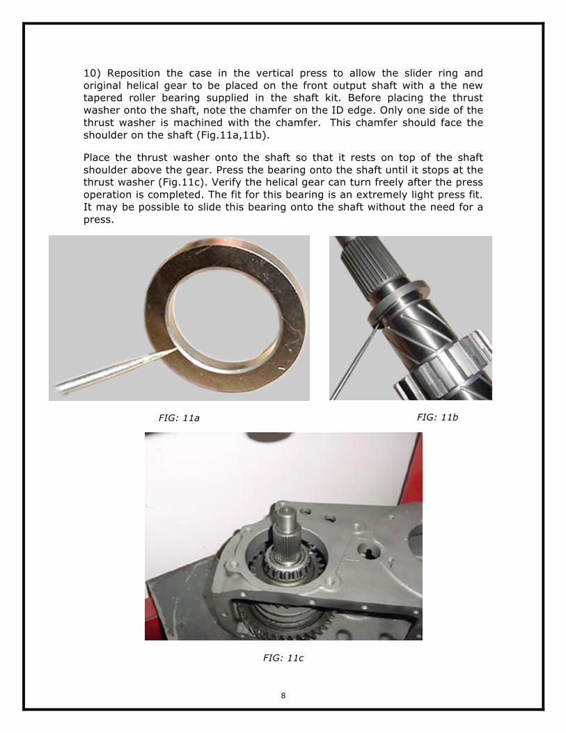
10) Reposition the case in the vertical press to allow the slider ring and original helical gear to be placed on the front output shaft with a the new tapered roller bearing supplied in the shaft kit. Before placing the thrust washer onto the shaft, note the chamfer on the ID edge. Only one side of the thrust washer is machined with the chamfer. This chamfer should face the shoulder on the shaft (Fig.11a,11b).
Place the thrust washer onto the shaft so that it rests on top of the shaft shoulder above the gear. Press the bearing onto the shaft until it stops at the thrust washer (Fig.11c). Verify the helical gear can turn freely after the press operation is completed. The fit for this bearing is an extremely light press fit. It may be possible to slide this bearing onto the shaft without the need for a press.
FIG: 11a
FIG: 11b
FIG: 11c

9
11) Place the bearing cup #M86610 into the rear bore of the case (Fig.12).
FIG: 12
12) Install the retainer plate (Fig.13) and original shim pack in place behind the bearing cup. Do not seal this plate yet. You may need to adjust the shim pack if endplay is determined to be incorrect after the front bearing retainer housing is installed.
FIG: 13

10
13) Install the bearing cup into the aluminum retainer housing. This step does require minimal machining of the stock-bearing retainer. Refer to the "bearing cup installation" drawing (ILLUS: 1) included with these instructions at the end.
ILLUS: 1 (see end of document)
14) Arrange the shift forks in the case to accommodate the rails (Fig.14).
FIG: 14
11
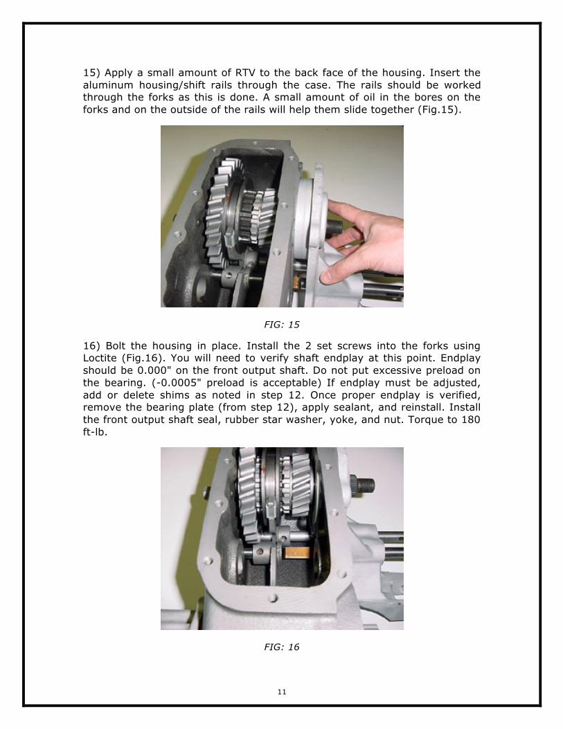
15) Apply a small amount of RTV to the back face of the housing. Insert the aluminum housing/shift rails through the case. The rails should be worked through the forks as this is done. A small amount of oil in the bores on the forks and on the outside of the rails will help them slide together (Fig.15).
FIG: 15
16) Bolt the housing in place. Install the 2 set screws into the forks using Loctite (Fig.16). You will need to verify shaft endplay at this point. Endplay should be 0.000" on the front output shaft. Do not put excessive preload on the bearing. (-0.0005" preload is acceptable) If endplay must be adjusted, add or delete shims as noted in step 12. Once proper endplay is verified, remove the bearing plate (from step 12), apply sealant, and reinstall. Install the front output shaft seal, rubber star washer, yoke, and nut. Torque to 180 ft-lb.
FIG: 16

12
17) Install the needle bearings into the idler gear using a thick grease (Fig.18). Remember to install the three steel rings along with the needle bearings. Be sure that all needle bearings are installed.
FIG: 18
18) Place one of the thrust washers into the case as shown (Fig.19). Coat both sides of the washer with thick grease and place it into the case properly. You can use the cross shaft as shown to hold the washer in place as you lower the idler gear into place (later in the installation of the gear).
FIG: 19

13
19) Place the second thrust washer into the case as shown. Again coat both sides with grease. The washer should stay in place easily (Fig.20).
FIG: 20
20) As you lower the idler into place in the next step, you can hold the thrust washer into place with your finger tip as shown (Fig.21).
FIG: 21

14
21) Roll the idler gear into place rotating it as it is lowered (Fig.22).
FIG: 22
22) When the idler gear is located properly, the intermediate shaft can be easily pushed through the center of the idler gear. Pay close attention and be sure all of the needle bearings remain in place during this procedure. Align the intermediate shaft with the flat side in the position shown. This will allow the retainer plate and bolt to be installed after the intermediate shaft is tapped into the final position (Fig.23,24). Install the shift rail caps if they have been removed.
FIG: 23
FIG: 24
23) Install the inspection cover to complete the assembly.

15
ILLUSTRATION 1