DampIT: A Tool for the Identification of Physical … A Tool for the Identification of Physical...
15
DampIT: A Tool for the Identification of Physical Damping Coefficients of a Multibody System Model SIMULIA Multibody Simulation User Group Meeting 2017 A. Rezaeian, J. Ruhnke, S. Hauptmann MesH Engineering GmbH [email protected] [email protected]
Transcript of DampIT: A Tool for the Identification of Physical … A Tool for the Identification of Physical...
DampIT: A Tool for the Identification of Physical Damping Coefficients of a Multibody System Model
SIMULIA Multibody Simulation User Group Meeting 2017
A. Rezaeian, J. Ruhnke, S. Hauptmann
MesH Engineering [email protected]
Content
▪ Motivation
▪ Objective
▪ Basic Principles
▪ Damping Coefficients Identification Process
▪ DampIT: Implementation of the Process
▪ Application of DampIT
▪ Conclusions
Nov. 7, 2017 SIMULIA Multibody Simulation User Group Meeting 2017 Page 2
Motivation
Nov. 7, 2017 SIMULIA Multibody Simulation User Group Meeting 2017 Page 3
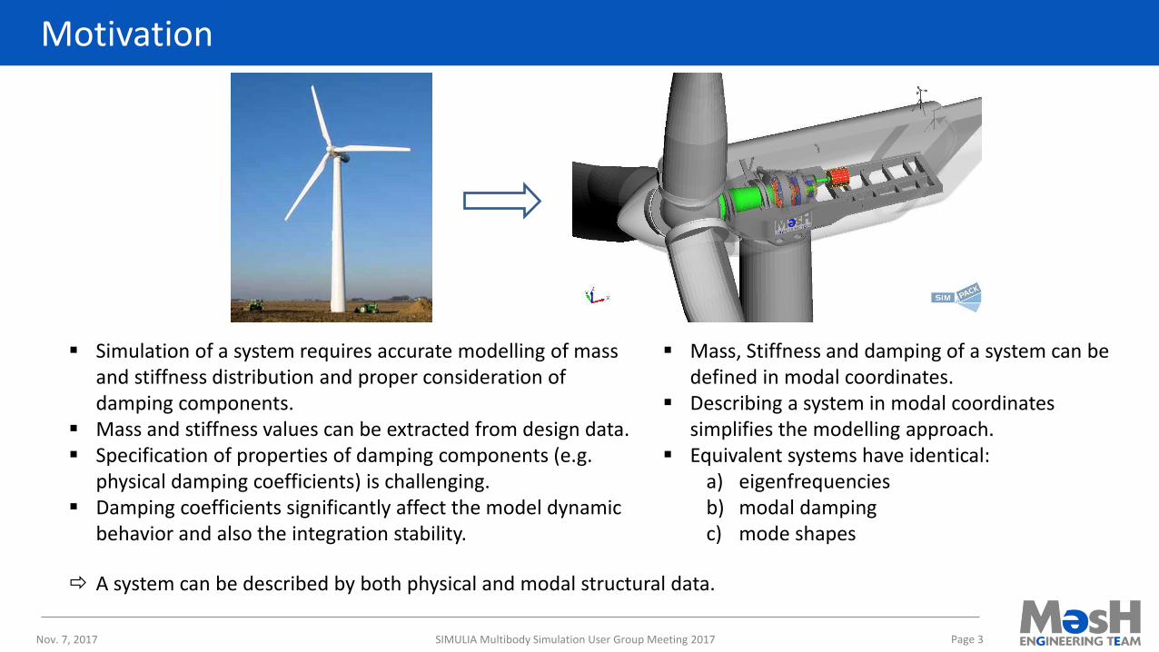
▪ Simulation of a system requires accurate modelling of mass and stiffness distribution and proper consideration of damping components.
▪ Mass and stiffness values can be extracted from design data. ▪ Specification of properties of damping components (e.g.
physical damping coefficients) is challenging.▪ Damping coefficients significantly affect the model dynamic
behavior and also the integration stability.
▪ Mass, Stiffness and damping of a system can be defined in modal coordinates.
▪ Describing a system in modal coordinates simplifies the modelling approach.
▪ Equivalent systems have identical:a) eigenfrequenciesb) modal dampingc) mode shapes
A system can be described by both physical and modal structural data.
Motivation
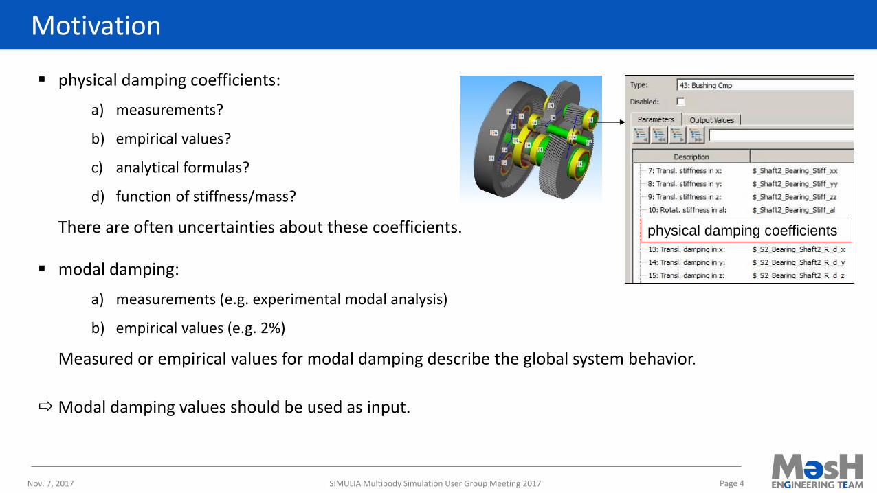
▪ physical damping coefficients:
a) measurements?
b) empirical values?
c) analytical formulas?
d) function of stiffness/mass?
There are often uncertainties about these coefficients.
▪ modal damping:
a) measurements (e.g. experimental modal analysis)
b) empirical values (e.g. 2%)
Measured or empirical values for modal damping describe the global system behavior.
Modal damping values should be used as input.
Nov. 7, 2017 SIMULIA Multibody Simulation User Group Meeting 2017 Page 4
physical damping coefficients
Objective
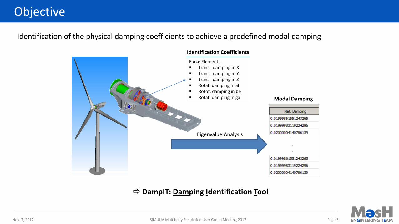
Identification of the physical damping coefficients to achieve a predefined modal damping
DampIT: Damping Identification Tool
Nov. 7, 2017 SIMULIA Multibody Simulation User Group Meeting 2017 Page 5
Eigenvalue Analysis
Force Element i▪ Transl. damping in X▪ Transl. damping in Y▪ Transl. damping in Z▪ Rotat. damping in al▪ Rotot. damping in be▪ Rotat. damping in ga
Identification Coefficients
Modal Damping
Basic Principles
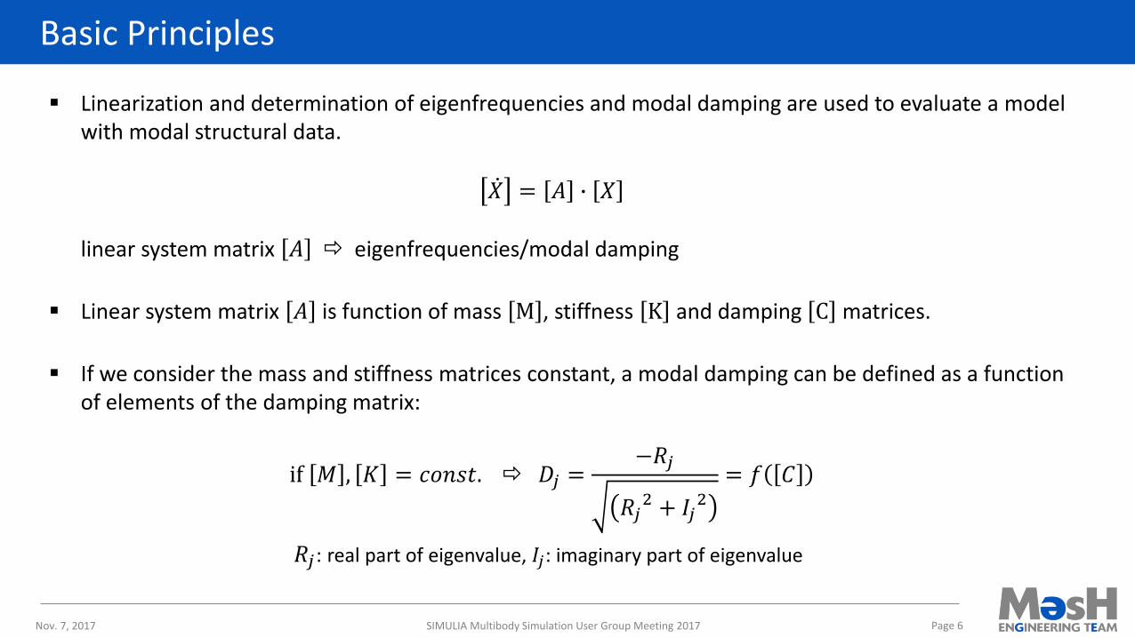
▪ Linearization and determination of eigenfrequencies and modal damping are used to evaluate a model with modal structural data.
ሶ𝑋 = 𝐴 ∙ 𝑋
linear system matrix 𝐴 eigenfrequencies/modal damping
▪ Linear system matrix 𝐴 is function of mass M , stiffness K and damping C matrices.
▪ If we consider the mass and stiffness matrices constant, a modal damping can be defined as a function of elements of the damping matrix:
if 𝑀 , 𝐾 = 𝑐𝑜𝑛𝑠𝑡. 𝐷𝑗 =−𝑅𝑗
𝑅𝑗2 + 𝐼𝑗
2
= 𝑓 𝐶
𝑅𝑗: real part of eigenvalue, 𝐼𝑗: imaginary part of eigenvalue
Nov. 7, 2017 SIMULIA Multibody Simulation User Group Meeting 2017 Page 6
Damping Coefficients Identification Process
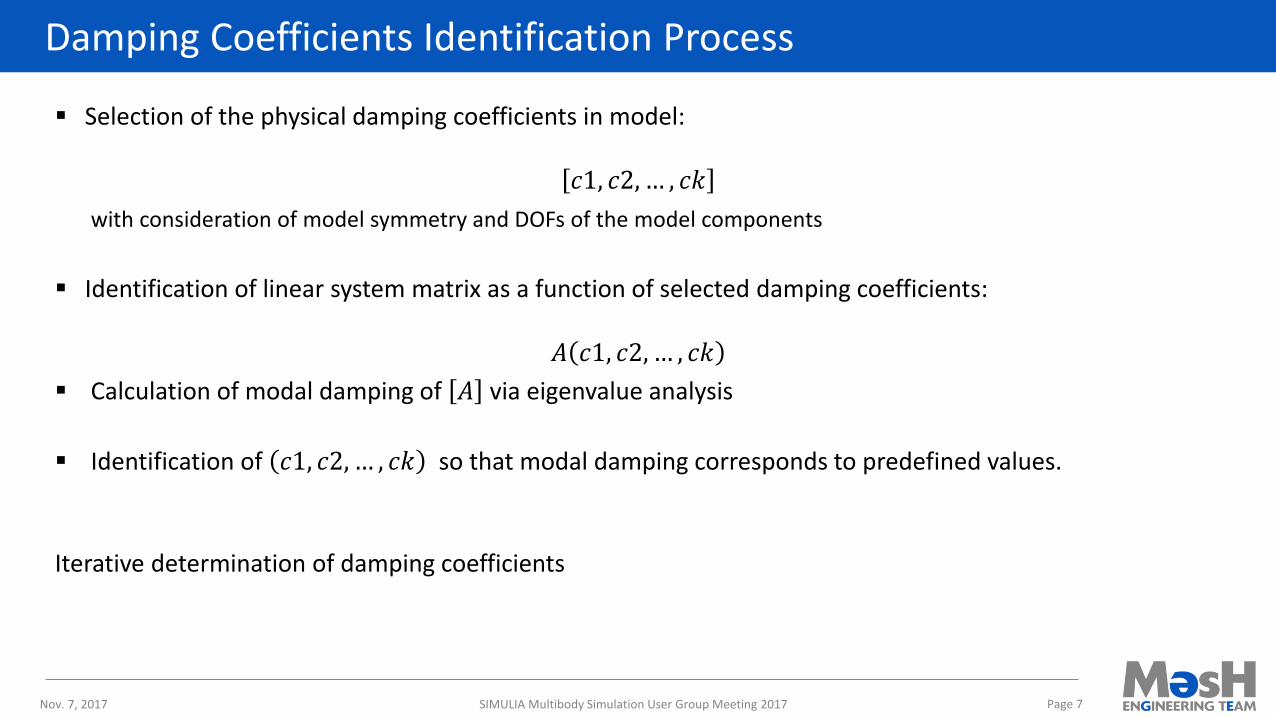
▪ Selection of the physical damping coefficients in model:
𝑐1, 𝑐2, … , 𝑐𝑘
with consideration of model symmetry and DOFs of the model components
▪ Identification of linear system matrix as a function of selected damping coefficients:
𝐴 𝑐1, 𝑐2, … , 𝑐𝑘
▪ Calculation of modal damping of 𝐴 via eigenvalue analysis
▪ Identification of 𝑐1, 𝑐2, … , 𝑐𝑘 so that modal damping corresponds to predefined values.
Iterative determination of damping coefficients
Nov. 7, 2017 SIMULIA Multibody Simulation User Group Meeting 2017 Page 7
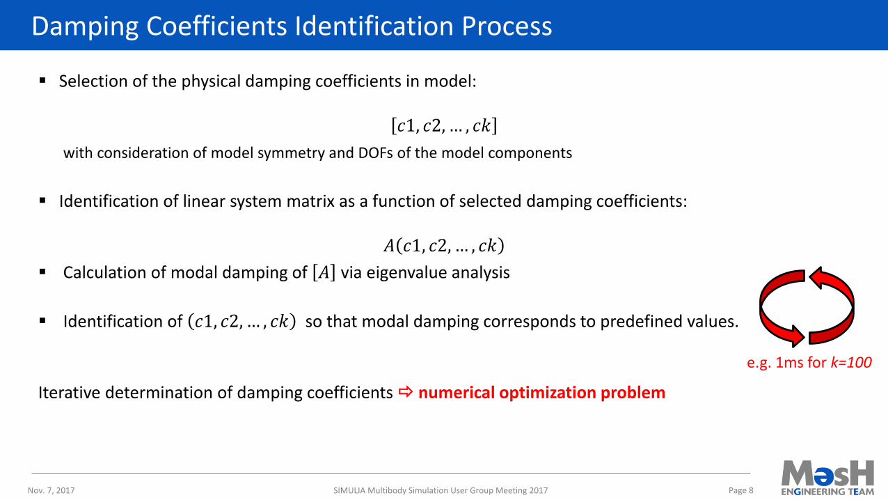
Damping Coefficients Identification Process
▪ Selection of the physical damping coefficients in model:
𝑐1, 𝑐2, … , 𝑐𝑘
with consideration of model symmetry and DOFs of the model components
▪ Identification of linear system matrix as a function of selected damping coefficients:
𝐴 𝑐1, 𝑐2, … , 𝑐𝑘
▪ Calculation of modal damping of 𝐴 via eigenvalue analysis
▪ Identification of 𝑐1, 𝑐2, … , 𝑐𝑘 so that modal damping corresponds to predefined values.
Iterative determination of damping coefficients numerical optimization problem
Nov. 7, 2017 SIMULIA Multibody Simulation User Group Meeting 2017 Page 8
e.g. 1ms for k=100
DampIT: Implementation of the Process
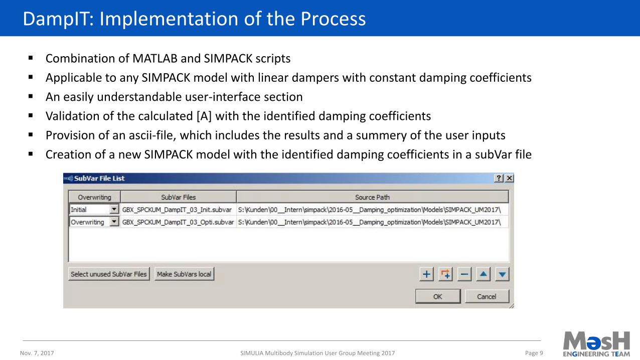
▪ Combination of MATLAB and SIMPACK scripts
▪ Applicable to any SIMPACK model with linear dampers with constant damping coefficients
▪ An easily understandable user-interface section
▪ Validation of the calculated [A] with the identified damping coefficients
▪ Provision of an ascii-file, which includes the results and a summery of the user inputs
▪ Creation of a new SIMPACK model with the identified damping coefficients in a subVar file
Nov. 7, 2017 SIMULIA Multibody Simulation User Group Meeting 2017 Page 9
Application of DampIT: Example 1
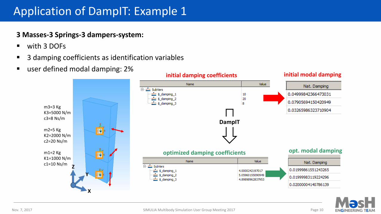
3 Masses-3 Springs-3 dampers-system:
▪ with 3 DOFs
▪ 3 damping coefficients as identification variables
▪ user defined modal damping: 2%
Nov. 7, 2017 SIMULIA Multibody Simulation User Group Meeting 2017 Page 10
initial modal dampinginitial damping coefficients
optimized damping coefficients opt. modal damping
DampIT
m3=3 Kg K3=5000 N/mc3=8 Ns/m
m2=5 Kg K2=2000 N/mc2=20 Ns/m
m1=2 KgK1=1000 N/mc1=10 Ns/m
Application of DampIT: Example 2
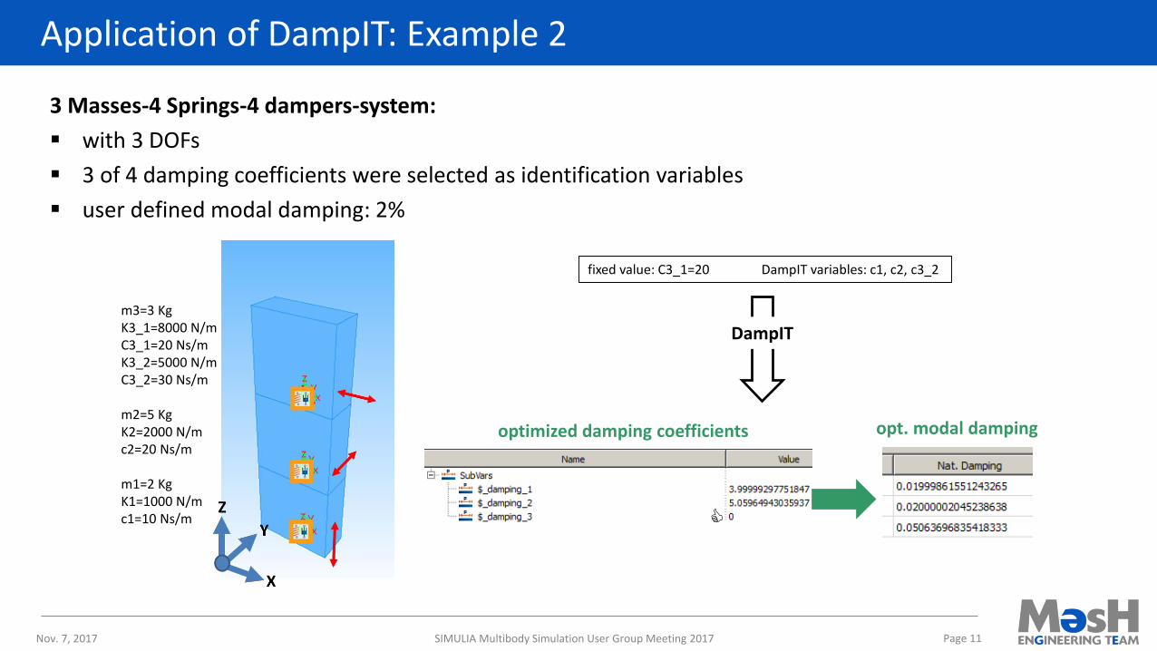
3 Masses-4 Springs-4 dampers-system:
▪ with 3 DOFs
▪ 3 of 4 damping coefficients were selected as identification variables
▪ user defined modal damping: 2%
Nov. 7, 2017 SIMULIA Multibody Simulation User Group Meeting 2017 Page 11
optimized damping coefficients opt. modal damping
DampIT
fixed value: C3_1=20 DampIT variables: c1, c2, c3_2
m3=3 KgK3_1=8000 N/mC3_1=20 Ns/mK3_2=5000 N/mC3_2=30 Ns/m
m2=5 KgK2=2000 N/mc2=20 Ns/m
m1=2 KgK1=1000 N/mc1=10 Ns/m
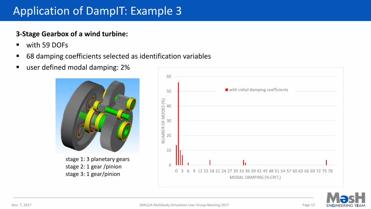
Application of DampIT: Example 3
3-Stage Gearbox of a wind turbine:
▪ with 59 DOFs
▪ 68 damping coefficients selected as identification variables
▪ user defined modal damping: 2%
Nov. 7, 2017 SIMULIA Multibody Simulation User Group Meeting 2017 Page 12
stage 1: 3 planetary gearsstage 2: 1 gear /pinionstage 3: 1 gear/pinion
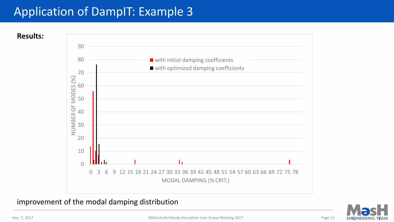
Application of DampIT: Example 3
Results:
improvement of the modal damping distribution
Nov. 7, 2017 SIMULIA Multibody Simulation User Group Meeting 2017 Page 13
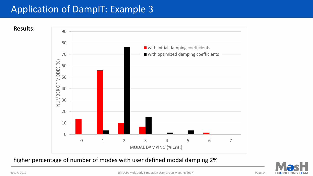
Application of DampIT: Example 3
Results:
higher percentage of number of modes with user defined modal damping 2%
Nov. 7, 2017 SIMULIA Multibody Simulation User Group Meeting 2017 Page 14
Conclusions
▪ Specification of damping of a system in modal coordinates is easier than in physical coordinates.
▪ It is possible in a model to adjust the physical damping coefficients to achieve a predefined modal damping:
a) DampIT: a tool for the identification of physical damping coefficients of a MBS-model to achieve a predefined modal damping was introduced.
b) Application of this tool was demonstrated for different examples.
c) Improvements of the damping coefficients using DampIT were shown and discussed.
DampIT is ready for customer application!
Nov. 7, 2017 SIMULIA Multibody Simulation User Group Meeting 2017 Page 15