Damping Mechanisms for Microgravity Vibration Isolation
21
NASA/TM–1998 –206953 January 1998 Damping Mechanisms for Microgravity Vibration Isolation (MSFC Center Director’s Discretionary Fund Final Report, Project No. 94–07) M.S. Whorton, J.T. Eldridge, R.C. Ferebee, J.O. Lassiter, and J.W. Redmon, Jr. Marshall Space Flight Center • MSFC, Alabama
Transcript of Damping Mechanisms for Microgravity Vibration Isolation
NASA/TM–1998–206953
January 1998
Damping Mechanisms for MicrogravityVibration Isolation(MSFC Center Director’s Discretionary Fund Final Report,Project No. 94–07)
M.S. Whorton, J.T. Eldridge, R.C. Ferebee, J.O. Lassiter, and J.W. Redmon, Jr.Marshall Space Flight Center • MSFC, Alabama
Since its founding, NASA has been dedicated tothe advancement of aeronautics and spacescience. The NASA Scientific and TechnicalInformation (STI) Program Office plays a keypart in helping NASA maintain this importantrole.
The NASA STI Program Office is operated byLangley Research Center, the lead center forNASA’s scientific and technical information. TheNASA STI Program Office provides access to theNASA STI Database, the largest collection ofaeronautical and space science STI in the world. TheProgram Office is also NASA’s institutionalmechanism for disseminating the results of itsresearch and development activities. These resultsare published by NASA in the NASA STI ReportSeries, which includes the following report types:
• TECHNICAL PUBLICATION. Reports ofcompleted research or a major significant phaseof research that present the results of NASAprograms and include extensive data ortheoretical analysis. Includes compilations ofsignificant scientific and technical data andinformation deemed to be of continuing referencevalue. NASA’s counterpart of peer-reviewedformal professional papers but has less stringentlimitations on manuscript length and extent ofgraphic presentations.
• TECHNICAL MEMORANDUM. Scientific andtechnical findings that are preliminary or ofspecialized interest, e.g., quick release reports,working papers, and bibliographies that containminimal annotation. Does not contain extensiveanalysis.
• CONTRACTOR REPORT. Scientific andtechnical findings by NASA-sponsoredcontractors and grantees.
• CONFERENCE PUBLICATION. Collectedpapers from scientific and technical conferences,symposia, seminars, or other meetings sponsoredor cosponsored by NASA.
• SPECIAL PUBLICATION. Scientific, technical,or historical information from NASA programs,projects, and mission, often concerned withsubjects having substantial public interest.
• TECHNICAL TRANSLATION.English-language translations of foreign scientificand technical material pertinent to NASA’smission.
Specialized services that complement the STIProgram Office’s diverse offerings include creatingcustom thesauri, building customized databases,organizing and publishing research results…evenproviding videos.
For more information about the NASA STI ProgramOffice, see the following:
• Access the NASA STI Program Home Page athttp://www.sti.nasa.gov
• E-mail your question via the Internet [email protected]
• Fax your question to the NASA Access HelpDesk at (301) 621–0134
• Telephone the NASA Access Help Desk at (301)621–0390
• Write to:NASA Access Help DeskNASA Center for AeroSpace Information800 Elkridge Landing RoadLinthicum Heights, MD 21090–2934
The NASA STI Program Office…in Profile
i
NASA/TM—1998 –206953
Damping Mechanisms for MicrogravityVibration Isolation(MSFC Center Director’s Discretionary Fund Final Report,Project No. 94–07)
January 1998
National Aeronautics andSpace Administration
Marshall Space Flight Center
M.S. Whorton, J.T. Eldridge, R.C. Ferebee, J.O. Lassiter, and J.W. Redmon, Jr.Marshall Space Flight Center • MSFC, Alabama
ii
Acknowledgments
The authors wish to acknowledge Dr. Gerald Nuree for his vision, expertise, leadership, and support of the mg vibrationisolation activities at Marshall Space Flight Center (MSFC) prior to his retirement in January 1997.
Available from:
NASA Center for AeroSpace Information National Technical Information Service800 Elkridge Landing Road 5285 Port Royal RoadLinthicum Heights, MD 21090–2934 Springfield, VA 22161(301) 621–0390 (703) 487–4650
iii
TABLE OF CONTENTS
1. INTRODUCTION ....................................................................................................................... 1
2. LITERATURE SEARCH ............................................................................................................3
3. VIBRATION ISOLATION FUNDAMENTALS ........................................................................ 5
4. CONTROL SYSTEM DESIGN CONSIDERATIONS .............................................................. 7
5. STABLE HARDWARE DESCRIPTION.................................................................................... 10
6. RELATED RESEARCH AND DEVELOPMENT ..................................................................... 11
REFERENCES ................................................................................................................................... 12

iv
1
TECHNICAL MEMORANDUM
DAMPING MECHANISMS FOR MICROGRAVITY VIBRATION ISOLATION(MSFC Center Director’s Discretionary Fund Final Report, Project No. 94–07)
1. INTRODUCTION
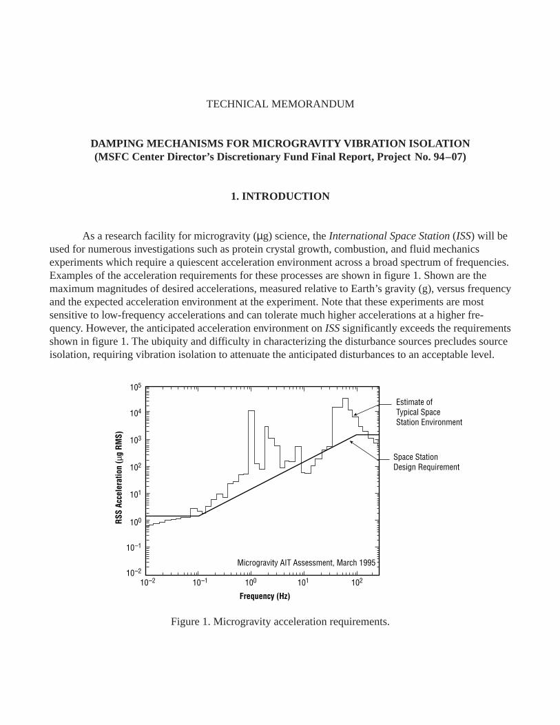
As a research facility for microgravity (µg) science, the International Space Station (ISS) will beused for numerous investigations such as protein crystal growth, combustion, and fluid mechanicsexperiments which require a quiescent acceleration environment across a broad spectrum of frequencies.Examples of the acceleration requirements for these processes are shown in figure 1. Shown are themaximum magnitudes of desired accelerations, measured relative to Earth’s gravity (g), versus frequencyand the expected acceleration environment at the experiment. Note that these experiments are mostsensitive to low-frequency accelerations and can tolerate much higher accelerations at a higher fre-quency. However, the anticipated acceleration environment on ISS significantly exceeds the requirementsshown in figure 1. The ubiquity and difficulty in characterizing the disturbance sources precludes sourceisolation, requiring vibration isolation to attenuate the anticipated disturbances to an acceptable level.
Figure 1. Microgravity acceleration requirements.
Estimate ofTypical SpaceStation Environment
Space StationDesign Requirement
Microgravity AIT Assessment, March 1995
10–210–2
10–1
100
101
102
103
104
105
10–1 100 101 102
Frequency (Hz)
RSS
Acce
lera
tion
(µg
RMS)
2
The primary sources of vibration on ISS can be categorized into three characteristic frequencyranges. At low frequencies, approximately 10–3 Hz, the dominant accelerations are caused by gravitygradients and atmospheric drag. These low-frequency vibrations are determined by ISS configurationand orbit choices. These accelerations are nontransient in nature, either slowly varying or periodic. Theacceleration caused by gravity gradient depends on the distance of the experiment from the center ofmass, and on the ISS configuration. The total acceleration in this low-frequency range will be less than10–5 g and can be made <10–6 g for some experiments placed close to the ISS center of mass. At highfrequencies, above ~1 Hz, the vibrations are caused by sinusoidal steady-state sources such as pumps,compressors, electric motors, and fans, as well as transient sources such as impacts, astronaut motion,and high-frequency components of thruster firings. This class of vibration sources has been measured onSpacelab and will require significant isolation to meet the desired vibration goals of ISS. Because oftheir relatively high frequency however, microgravity experiments can be isolated from these vibrationswith relatively simple (possibly passive) vibration isolation systems. The third characteristic frequencyrange of vibrations is the intermediate range of ~10–3 Hz to 1 Hz. The sources of acceleration in thisrange are mostly transient in nature, such as the motion of astronauts and payloads around the ISS, aswell as the motion of the ISS caused by thrusters. Because of their transient nature, the effect of thesevibrations on many experiments is difficult to analyze. The calculation of the resultant accelerations ofthe ISS at the upper end of this frequency range is also complicated by the interaction of these vibrationsources with the structural modes of the ISS.
An example of these transient disturbances is the motion of the ISS crew. The large-scale motionof the crew leads to significant accelerations and displacements of the ISS. An example calculationresults in peak accelerations of 9×10⁻⁴ g for a 220,000 lbm ISS. During this soaring maneuver, theastronaut moves 48 ft and the ISS moves 0.4 in. In the high-frequency range, passive isolation techniquesare often adequate to provide sufficient attenuation of vibration disturbances. However, isolation of low-and intermediate-frequency vibrations is not possible with passive isolation and therefore requires activeisolation. Hence, the development of active isolation systems is imperative to provide a quiescent accel-eration environment as required by many µ g science investigations.
Because vibration isolation plays such a significant role in MSFC’s missions in µg science, theCenter Director’s Discretionary Fund (CDDF) Project Number 94–07 was initiated. This project, en-titled “Damping Mechanisms for Microgravity Vibration Isolation,” was undertaken to develop anexpertise in vibration isolation systems for µg payloads. Three objectives were identified: first, surveythe state of the art in µg isolation technology; second, develop testing capabilities for low-frequency,low-acceleration isolation systems; and third, perform component tests of existing isolator technologies.
3
2. LITERATURE SEARCH
Much work has been done during the past several years toward the development of active isola-tion systems for µg payloads. The NASA Lewis Research Center (LeRC) conducted an AdvancedTechnology Development Project in Vibration Isolation Technology from 1987 through 1992 whichsponsored in-house technology and funded numerous contractor studies and hardware development.1 Asix degree-of-freedom (DOF) laboratory test-bed was developed to evaluate concepts and control strate-gies which led to an aircraft test-bed system that was successfully tested on the NASA LeRC Learjet.Based on two decades of experience in active suspension systems, the Honeywell Corporation (formerlySperry) developed the first isolation system for space shuttle flight applications called the Fluids Experi-ment Apparatus Magnetic Isolation System (FEAMIS) to support Rockwell’s Fluid Experiment Appara-tus (FEA).2 However, FEAMIS was never flown. McDonnell Douglas Aerospace Corporation (MDAC)developed a six DOF active isolation system using piezoelectric polymer film actuators.3 In early 1995,MSFC joined with MDAC to develop a vibration isolation system called Suppression of TransientAccelerations By Levitation (STABLE).4 STABLE utilized noncontact electromagnetic actuatorsdeveloped for a helicopter imaging system. The STABLE flight experiment on STS–73 was the firstsuccessful µg vibration isolation system to be flown in space and was made possible, in part, by thetechnology developed through this CDDF project. The Canadian Space Agency has developed a systemcalled the Microgravity Vibration Isolation Mount (MIM). MIM began operation aboard the Russian MirSpace Station during 1996 and was flight-tested on the space shuttle flight STS–85 in August 1997. Thedesign approach selected as part of the ISS µg control plan is to provide isolation to an entire rack usingthe Active Rack Isolation System (ARIS) developed by The Boeing Corp.5 ARIS uses voice-coil actua-tors with pushrods to attenuate disturbances transmitted through the utility umbilicals to the isolatedrack. Based on the large mass and low stiffness of the umbilicals and actuator flexures, ARIS relies onpassive attenuation above frequencies in the 5-Hz range. ARIS was flight-tested on STS–79 in Septem-ber 1996.6 An isolation system, called the Microgravity Isolation Mount (MGIM) was developed by theEuropean Space Agency and tested in the laboratory to support Space Station research.7 Satcon Corp.developed a ground test version of a six DOF vibration isolation system as did Applied TechnologyAssociates, Inc. with a three DOF system. With the exception of the ARIS voice-coil/pushrod actuatorand the MDAC piezoelectric polymer film actuator, each of the systems described above usesnoncontacting electromagnetic actuators to isolate an individual experiment.
The other objectives of the CDDF project were to develop µg isolation test capabilities andperform component testing. Toward this end, a µg vibration control laboratory was developed. The firstphase of this lab facility consisted of a pendulous “gallows” support structure mounted on an isolationtable. By suspending both the isolated portion and the nonisolated base, the transmissibility of an isola-tion system could be tested in as many as three DOF. This facility was used to perform functional verifi-cation tests on the STABLE flight hardware. During STABLE verification testing, several deficiencieswith this approach were observed. Testing for vibration isolation at the microgravity level is not a trivialtask due to gravitational coupling and environmental disturbances. One particular problem was thecoupling between translation and rotation of the suspended platform. Since a unit µ radian angular

4
displacement from the horizontal plane is measured as a unit µg disturbance acceleration, the couplingintroduced errors that were too large for the control system to overcome. Also, longitudinal flexure ofthe suspension cables transmitted undesirable disturbances to the suspended platform. As a result oflessons learned during STABLE verification testing, a second phase of this facility is under developmentwhich utilizes air pads on an isolation table for suspension of the platform.
5
3. VIBRATION ISOLATION FUNDAMENTALS
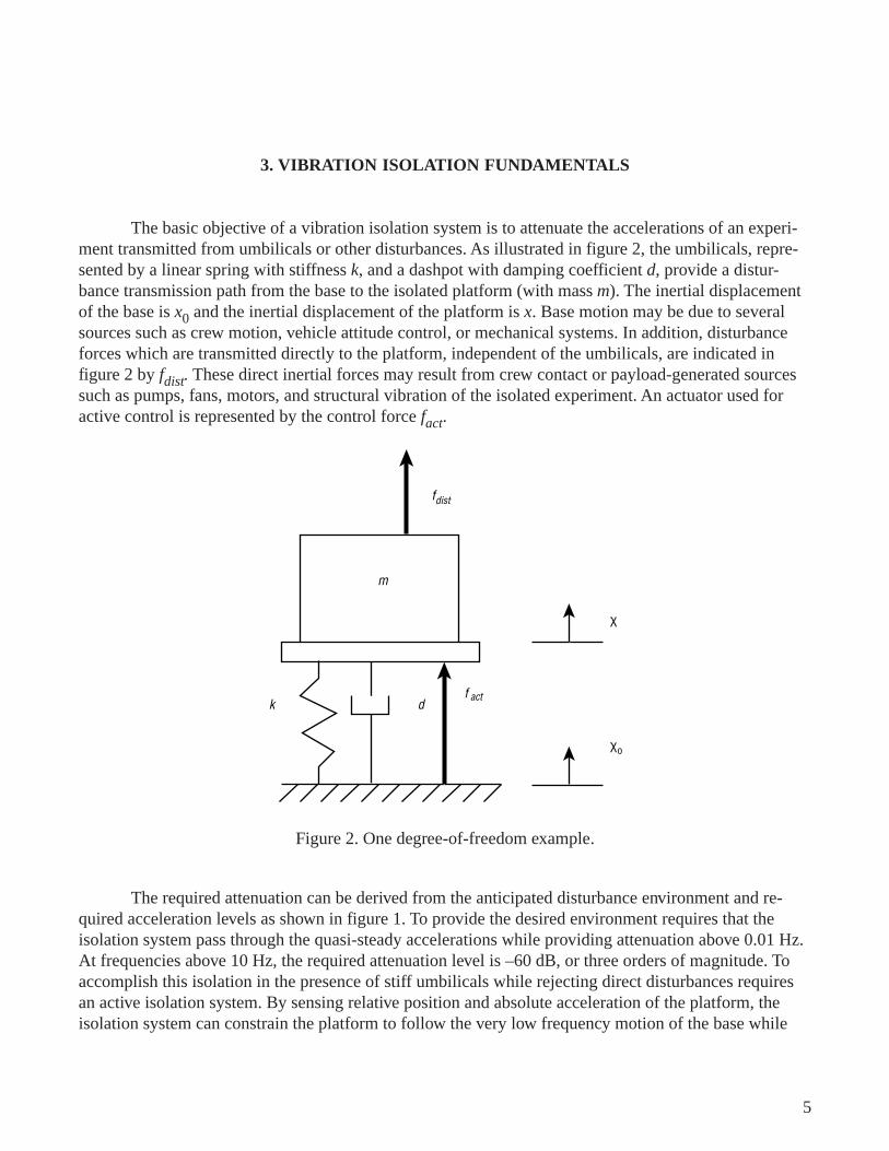
The basic objective of a vibration isolation system is to attenuate the accelerations of an experi-ment transmitted from umbilicals or other disturbances. As illustrated in figure 2, the umbilicals, repre-sented by a linear spring with stiffness k, and a dashpot with damping coefficient d, provide a distur-bance transmission path from the base to the isolated platform (with mass m). The inertial displacementof the base is x0 and the inertial displacement of the platform is x. Base motion may be due to severalsources such as crew motion, vehicle attitude control, or mechanical systems. In addition, disturbanceforces which are transmitted directly to the platform, independent of the umbilicals, are indicated infigure 2 by fdist. These direct inertial forces may result from crew contact or payload-generated sourcessuch as pumps, fans, motors, and structural vibration of the isolated experiment. An actuator used foractive control is represented by the control force fact.
The required attenuation can be derived from the anticipated disturbance environment and re-quired acceleration levels as shown in figure 1. To provide the desired environment requires that theisolation system pass through the quasi-steady accelerations while providing attenuation above 0.01 Hz.At frequencies above 10 Hz, the required attenuation level is –60 dB, or three orders of magnitude. Toaccomplish this isolation in the presence of stiff umbilicals while rejecting direct disturbances requiresan active isolation system. By sensing relative position and absolute acceleration of the platform, theisolation system can constrain the platform to follow the very low frequency motion of the base while
k df
fdist
m
act
χ
χo
Figure 2. One degree-of-freedom example.
6
attenuating the base motion above 0.01 Hz. High-bandwidth acceleration feedback, in essence, effec-tively increases the dynamic mass of the platform which reduces the response to direct disturbances.Demonstration of this level of performance in six DOF cannot be accomplished on the ground due togravitational coupling, but requires testing in a µg environment. Long periods of experimentation arenecessary to characterize the low-frequency behavior, which is the most critical frequency range foractive vibration isolation.
In general, an active vibration isolation system can be characterized by three parameters: re-quired stroke, maximum isolation frequency, and force. If the isolation system were required to reducethe residual acceleration of the isolated mass to zero, the required stroke for each of the vibrationsources would be the peak-to-peak displacement of ISS resulting from these sources. For the low-frequency disturbances, such as the attitude control, gravity gradient, and reboost thrust, the actuatorstrokes required to reduce the accelerations to zero are prohibitively large, >1 m. Isolation of these lowerfrequency disturbances is not practical since excessively large stroke actuators would be required.Isolation from higher frequency steady-state vibration sources such as pumps, machinery, etc. requiresonly a relatively small gap (stroke) suspension of <1 cm. The hardest vibrations to isolate in order tomeet the formal ISS requirement are the transient vibrations caused by crew motion. Elimination of thesetransient vibrations may require isolators with strokes over 1 cm.
The limited gap (stroke) of any isolation system requires that it force the isolated body to followthe ISS at low frequencies, which sets the break frequency of the transmissibility function. Since isola-tion below 10–3 Hz will require strokes exceeding a few centimeters, a reasonable isolator transmissibil-ity function will have a break frequency of ~10–2 Hz. The control system bandwidth determines thespectrum of direct disturbances that may be attenuated. This bandwidth is limited typically to between5 and 50 Hz in order to prevent undesirable excitation of structural modes and amplification of measure-ment noise.
The third basic parameter needed to design the isolation system is the maximum force it mustproduce. A reasonable estimate of this force is simply the maximum acceleration times the isolatedmass. For a 100-kg (220-lbm) experiment meeting the formal ISS isolation goal, this requires a forcecapability of ~0.0025 lbf. Although this is enough force capability for normal operation, there may besome short-duration, high-acceleration transients that require higher forces. Transient vibrations causedby crew motion, resulting in an acceleration of 9×10⁻⁴, could be isolated with a force capability of~0.25 lbf for a 220-lbm experiment. Of course the actuator must be able to maintain this dynamic forcerange in addition to whatever bias forces are transmitted by the umbilical system when the isolatedpayload is centered in the swayspace. A secondary “bias elimination” stage could be employed to de-form the umbilicals in the appropriate manner to remove the bias force required by the isolation stage.The necessity of this coarse stage would be determined by the characteristics of the umbilical system.
7
4. CONTROL SYSTEM DESIGN CONSIDERATIONS
To illustrate the need for active isolation, consider the one-DOF spring-mass-damper system infigure 2. The response of the platform to base motion and direct inertial disturbances is
mx d x x k x x f fdist act˙̇ ˙ ˙+ −( ) + −( ) = +0 0 . (1)
The transmissibility function is defined as the ratio of platform acceleration to base acceleration and maybe obtained by taking Laplace transforms of equation (1), resulting in
X s
X s
s
s s
( )
( )0
2
2 22
2= +
+ +ζω ω
ζω ω , (2)
where the natural (or break) frequency is ω = k
m and ζ = d
km2 is the percent damping ratio. This
passive system behaves like a low-pass filter, transferring disturbances with frequencies below the
damped natural frequency, ω ω ζd = −1 2 , and attenuating disturbances above ωd . The slope of theattenuation function above ωd depends on the damping, but for an undamped system is –40 dB/decade.Thus, better isolation is obtained by decreasing the umbilical stiffness, k, or increasing the platform/payload mass, m. It is typically not desirable to increase the payload mass, so the umbilicals are de-signed to minimize stiffness. However, for small payload masses, achieving isolation at frequencieslower than 1 Hz by reducing stiffness is not possible with reasonable rattlespace constraints (±1 cm).
To improve upon the attenuation of direct disturbances by the passive system shown in figure 2,either the platform mass must increase or a stiff spring must connect the platform to the base (or better,to inertial space). Obviously the objectives of base motion isolation and direct disturbance rejection arein opposition for a small payload mass and cannot be achieved with passive isolation. That is not thecase with an actively controlled isolation system.
For example, consider a control law using feedback of absolute acceleration, relative velocity,and relative position described by
f K x x K x x K x xact a v p= − −( ) − −( ) − −( )˙̇ ˙̇ ˙ ˙0 0 0 . (3)
Substituting equation (3) into equation (1) yields the closed-loop equations of motion:
m K x d K x x k K x x fa v p dist+( ) + +( ) −( ) + +( ) −( ) =˙̇ ˙ ˙0 0 . (4)
8
Taking Laplace transforms results in the closed-loop transmissibility function
X s
X s
s
s sCL CL CL
CL CL CL
( )
( )0
2
2 22
2= +
+ +ζ ω ω
ζ ω ω , (5)
where the closed-loop natural frequency is
ωCLp
a
k K
m K=
++ (6)
and the closed-loop damping ratio is
ζCLv
p a
d K
k K m K= +
+( ) +( )2 . (7)
Comparing the open-loop (passive) system with the closed-loop system indicates that the gains(Ka, Kv, Kp) may be viewed as effective mass, damping, and stiffness, respectively, and may be used tomodify the dynamic response of the system. For a fixed umbilical stiffness and payload mass, the breakfrequency can be reduced by either using positive position feedback (Kp < 0) to negate the spring stiff-ness or by using high gain acceleration feedback (large Ka). Stiffness cancellation is not a sound ap-proach for stability reasons and acceleration feedback is preferable. Acceleration feedback is also benefi-cial for attenuating direct disturbances by effectively increasing the dynamic mass of the isolated pay-load.
Additional performance and stability improvements can be made by using more advanced opti-mal control techniques. Frequency-weighted linear-quadratic-Gaussian (LQG) design seeks to minimizea quadratic cost functional (an H2 norm) that is related to the energy of the system response and theenergy of the control system input. Since an objective of vibration isolation is to minimize the mean-square acceleration of the payload, H2 methods are well suited for control design.8–10
A key shortcoming of H2 methods is the lack of stability and performance robustness with re-spect to model errors. A robust control design approach for µg vibration isolation must account foruncertainties in umbilical properties, mass, cg location, actuator/sensor dynamics, and uncertain orunmodeled plant dynamics. Using an H∞ norm framework, optimal controllers may be designed toprovide robust stability and performance guarantees for bounded model errors. However, the H∞ normis related to the system gain so that the resulting controller seeks to minimize the peak frequency re-sponse magnitude.11,12 This performance metric is typically not as well suited to the vibration isolationproblem as the H2 norm. H∞ design also tends to be overly conservative when the uncertainty has struc-ture such as is encountered with parametric uncertainty or when designing for robust performance. This
9
conservatism is somewhat lessened using µ−synthesis methods which modify the H∞ design plant withfrequency-varying weights that are optimized with respect to the uncertainty structure.13–15
Recent advancements in control theory have addressed designing for nominal performance usingan H2 norm and robust stability using an H∞ norm. This so-called mixed H2/H∞ control design methodol-ogy is a combined approach which seeks to maximize H2 performance subject to robust stability con-straints. Mixed H2/H∞ control design is well suited for vibration isolation and has been applied to con-trolling the structural vibration of buildings subject to earthquake excitation16 as well as pointing controlof flexible space structures.17 The application of mixed H2/H∞ control design to the µg vibration isola-tion problem is in progress.
10
5. STABLE HARDWARE DESCRIPTION
As a result of the technology developed through this CDDF effort, MSFC teamed with MDACin early 1995 to jointly develop a µg vibration isolation system called STABLE. This effort culminatedin the first flight of an active µg vibration isolation system on STS–73/USML–02 in late 1995. Havingbeen given authorization to proceed in mid-January 1995, the schedule required delivery of flight hard-ware to the NASA Kennedy Space Center during the first week of June 1995. This unprecedentedaggressive schedule required design, analysis, fabrication, procurement, integration, testing, and deliveryof qualified flight hardware in less than 5 months. A successful delivery and flight experiment was madepossible in part by the technology and µg vibration isolation system test capabilities developed at MSFCthrough this CDDF project.
The STABLE system provides component-level isolation as an alternative to the rack-levelapproach. The concept of isolating only the vibration-sensitive portion of a payload minimizes thenumber and size of any utility umbilicals, since the floating portion of the payload is not necessarilyconnected to all onboard support systems. In multiexperiment racks, it also protects each individualpayload regardless of disturbances produced by nearby experiments, including servicing activitiesby the crew. Component-level isolation also eliminates the potential for disturbances due to accidentalcrew contact with the rack or its enclosure.
The STABLE hardware, in the configuration successfully flown on STS–73, provided an uninter-rupted µg environment for a fluid dynamics experiment dubbed “CHUCK.” Both experiments werecontained within a single middeck locker. In addition to providing a µg environment to the onboardexperiment, STABLE transferred power, data, and video signals to the platform by flexible umbilicalcables. The platform and CHUCK were levitated by three MDAC dual-axis, wide-gap electromagneticactuators.
STABLE isolates by floating a platform on electromagnetic actuators that apply forces to coun-teract those that are transmitted through umbilicals or that originate within the experiment itself. Accel-erations caused by these disturbing forces are measured by accelerometers on the platform, and thesesignals are used by a high-bandwidth feedback controller to command the counteracting actuator forces.In addition to the acceleration controller, there is a very low-bandwidth position loop that tends to keepthe platform centered. Signals from three, two-axis optical sensors measure the position of the platformwith respect to the base and are used to maintain centering. The centering function compensates for theextremely low-frequency disturbances for which adequate rattle space cannot be provided.
11
6. RELATED RESEARCH AND DEVELOPMENT
The technology developed during the CDDF Project Number 94–07 laid a foundation for con-tinuing activities in the area of µg vibration isolation. The foremost significant development resultingfrom the CDDF project has been the first successful µg vibration isolation flight experiment, STABLE.As a result of the expertise developed during the CDDF 94–07 and STABLE projects, team memberswere tasked to perform an independent technical assessment of the Boeing ARIS for the Space Station.Additional technical support has been given to the ARIS team in test, verification, and flight operationsfor the ARIS Risk Mitigation Flight Experiment on STS–79 in September 1996. Technical support forARIS in preparation for space station operation is currently ongoing. Additionally, an Advanced Tech-nology Development (ATD) project has been funded by NASA Headquarters Code UG/MicrogravityScience and Applications Division for fiscal years 1997–1999. The objective of this ATD project is todevelop the technology and ground test a small, modular vibration isolation system that can be used inthe space station glovebox. A proposal to develop a flight hardware version for use in the Space Stationglovebox has been approved with delivery anticipated during FY2000.
12
REFERENCES
1. Lubomski, J.F.; Grodsinsky, C.M.; Logsdon, K.A.; Rohn, D.A.; and Ramachanadran, N.: “FinalReport—Vibration Isolation Technology (vit) ATD Project.” NASA Technical Memorandum 106496,March 1994.
2. Allen, T.S.; Havenhill, D.D.; and Kral Feamis, K.D.; “A Magnetically Suspended Isolation Systemfor Space-Based Materials Processing.” In AAS Guidance and Control Conference, Keystone, CO,February 1986.
3. Edberg, D.L.; and von Flotow, A.: “Design Considerations for a Microgravity Vibration IsolationSystem.” In Proceedings of The AIAA/AHS/ASEE Aerospace Design Conference, Irvine, CA,February 1993. AIAA Paper 93–1116.
4. Edgerg, D.; Boucher, R.; Schenck, D.; Nurre, G.; Whorton, M.; Kim, Y.; and Alhorn, D.: “Results ofthe Stable Microgravity Vibration Isolation Flight Experiment.” R.D. Culp and M. Odefey, editors,Guidance and Control 1996, Vol. 92, Advances in the Astronautical Sciences, 1996. AAS Paper96–071.
5. Microgravity Control Plan, International Space Station Program. NASA Johnson Space Center,February 1997. Revision B, Draft.
6. Bushnell, G.: STS–79 Quick-Look Report, RME-1313. Document No. sk683–62235–1, BoeingDefense & Space Group, Research & Technology, 1996.
7. Owen, R.G.; Jones, D.I.; and Owens, A.R.: “Mechanical Design and Simulation of a MicrogravityIsolation Mount for Columbus.” Journal of Spacecraft and Rockets, Vol. 30, No. 4, 1993.
8. Knospe, C.R.; Hampton, R.D.; and Allaire, P.E.: “Control Issues of Microgravity Vibration Isola-tion.” Acta Astronautica, Vol. 25, No. 11, pp. 687–697, 1991.
9. Hampton, R.D., Knospe, C.R.; and Grodsinsky, C.: “Microgravity Isolation System Design: AModern Control Synthesis Framework.” Journal of Spacecraft and Rockets, Vol. 33, No. 1,pp. 101–109, 1996.
10. Hyde, T.T.; and Crawley, E.F.: “H2 Synthesis for Active Vibration Isolation.” In Proceedings of theAmerican Controls Conference, Seattle, WA, June 1995.
11. Francis, B.A.: A Course in H∞ Control Theory. Springer-Verlag, Berlin, 1987.
13
12. Doyle, J.C.; Glover, K.; Khargonekar, P.P.; and Francis, B.A.: “State-Space Solutions to Standard H2and H∞ Control Problems.” IEEE Transactions on Automatic Control, Vol. 34, No. 8, pp. 831–947,August 1989.
13. Doyle, J.C.: “Analysis of Feedback Systems With Structured Uncertainties.” In ProceedingsIEE–D 129, 1982.
14. Doyle, J.C.: Lecture notes on advances in multivariable control. Technical Report, ONR/HoneywellWorkshop on Advances in Multivariable Control, Minneapolis, MN, October 1984.
15. Doyle, J.C.; and Chu, C.C.: “Robust Control of Multivariable and Large Scale Systems.” TechnicalReport, AFOSR, March 1986. Final Technical Report for Contract No. F49620–84–C–0088.
16. Whorton, M.S.; Calise, A.J.; and Hsu, C.C.: A Study of Fixed Order Mixed Norm Designs for aBenchmark Problem in Structural Control. Earthquake Engineering and Structural Dynamics. To bepublished.
17. Whorton, M.S.: High Performance, Robust Control of Flexible Space Structures. Ph.D. Thesis,Georgia Institute of Technology, Atlanta, GA, August 1997.

14
16
REPORT DOCUMENTATION PAGE Form ApprovedOMB No. 0704-0188
Public reporting burden for this collection of information is estimated to average 1 hour per response, including the time for reviewing instructions, searching existing data sources,gathering and maintaining the data needed, and completing and reviewing the collection of information. Send comments regarding this burden estimate or any other aspect of thiscollection of information, including suggestions for reducing this burden, to Washington Headquarters Services, Directorate for Information Operation and Reports, 1215 JeffersonDavis Highway, Suite 1204, Arlington, VA 22202-4302, and to the Office of Management and Budget, Paperwork Reduction Project (0704-0188), Washington, DC 20503
1. AGENCY USE ONLY (Leave Blank)
17. SECURITY CLASSIFICATIONOF REPORT
NSN 7540-01-280-5500 Standard Form 298 (Rev. 2-89)Prescribed by ANSI Std. 239-18298-102
14. SUBJECT TERMS
13. ABSTRACT (Maximum 200 words)
12a. DISTRIBUTION/AVAILABILITY STATEMENT
11. SUPPLEMENTARY NOTES
6. AUTHORS
7. PERFORMING ORGANIZATION NAMES(S) AND ADDRESS(ES) 8. PERFORMING ORGANIZATIONREPORT NUMBER
9. SPONSORING/MONITORING AGENCY NAME(S) AND ADDRESS(ES) 10. SPONSORING/MONITORINGAGENCY REPORT NUMBER
4. TITLE AND SUBTITLE 5. FUNDING NUMBERS
12b. DISTRIBUTION CODE
18. SECURITY CLASSIFICATIONOF THIS PAGE
19. SECURITY CLASSIFICATIONOF ABSTRACT
20. LIMITATION OF ABSTRACT
16. PRICE CODE
15. NUMBER OF PAGES
2. REPORT DATE 3. REPORT TYPE AND DATES COVERED
Technical Memorandum
M–849
20
A03
January 1998
Damping Mechanisms for Microgravity Vibration Isolation(MSFC Center Director’s Discretionary Fund Final Report,Project No. 94–07)
M.S. Whorton, J.T. Eldridge, R.C. Ferebee, J.O. Lassiter, andJ.W. Redmon, Jr.
George C. Marshall Space Flight CenterMarshall Space Flight Center, Alabama 35812
National Aeronautics and Space AdministrationWashington, DC 20546-0001
Prepared by Structures and Dynamics Laboratory, Science and Engineering Directorate
Unclassified–UnlimitedSubject Category 18Nonstandard Distribution
Unclassified Unclassified Unclassified Unlimited
microgravity vibration isolation, robust control
NASA/TM—1998–206953
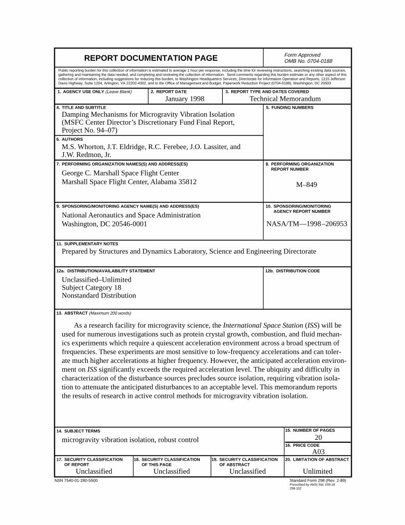
As a research facility for microgravity science, the International Space Station (ISS) will be used for numerous investigations such as protein crystal growth, combustion, and fluid mechan-ics experiments which require a quiescent acceleration environment across a broad spectrum of frequencies. These experiments are most sensitive to low-frequency accelerations and can toler-ate much higher accelerations at higher frequency. However, the anticipated acceleration environ-ment on ISS significantly exceeds the required acceleration level. The ubiquity and difficulty in characterization of the disturbance sources precludes source isolation, requiring vibration isola-tion to attenuate the anticipated disturbances to an acceptable level. This memorandum reports the results of research in active control methods for microgravity vibration isolation.