Damage Study and Future Direction for Structural Design ... · tornadoes touched down and moved...
56
1 Damage Study and Future Direction for Structural Design Following the Tuscaloosa Tornado of 2011 David O. Prevatt, Ph.D., P.E., University of Florida, Gainesville, FL John W. van de Lindt, Ph.D., University of Alabama, Tuscaloosa, AL Andrew Graettinger, Ph.D., University of Alabama, Tuscaloosa, AL William Coulbourne, P.E., Applied Technology Council, Rehoboth Beach, DE Rakesh Gupta, Ph.D., Oregon State University, Corvallis, OR Shiling Pei, Ph.D., P.E., South Dakota State University, Brookings, SD Samuel Hensen, P.E., Simpson Strong Tie, Pleasanton, CA David Grau, Ph.D., University of Alabama, Tuscaloosa, AL July 27, 2011
Transcript of Damage Study and Future Direction for Structural Design ... · tornadoes touched down and moved...

1
Damage Study and Future Direction for Structural Design Following the Tuscaloosa
Tornado of 2011
David O. Prevatt, Ph.D., P.E., University of Florida, Gainesville, FL John W. van de Lindt, Ph.D., University of Alabama, Tuscaloosa, AL Andrew Graettinger, Ph.D., University of Alabama, Tuscaloosa, AL
William Coulbourne, P.E., Applied Technology Council, Rehoboth Beach, DE Rakesh Gupta, Ph.D., Oregon State University, Corvallis, OR
Shiling Pei, Ph.D., P.E., South Dakota State University, Brookings, SD Samuel Hensen, P.E., Simpson Strong Tie, Pleasanton, CA David Grau, Ph.D., University of Alabama, Tuscaloosa, AL
July 27, 2011

2
TABLE OF CONTENTS I. Disclaimer …………………………………………………...………….…3 II. Chapter 1- Tuscaloosa Tornado Overview …………………………..…...4 III. Chapter 2- Inspection Methodology ……………...…………………….10 IV. Chapter 3- Existing Design Paradigm …………………………..……...24 V. Chapter 4- Building Performance – Case Studies ..……………………..28 VI. Chapter 5 - A Dual Objective-Based Design Philosophy for Tornado Engineering…………………………………………………………….…....41 VII. Chapter 6- Conclusions and Recommendations ……………..……......52 VIII. Acknowledgements ………………………………………...……...….55 IX. References …………………………………………………..……...…..56
3
Disclaimer
The opinions and views expressed by the authors in this
report are theirs alone and do not represent the view of any funding agencies. All information in this report is believed by the authors to be factually correct, but readers should use any
information contained herein at their own risk.

4
CHAPTER 1 –TUSCALOOSA TORNADO OVERVIEW
The severe weather that took the lives of 243 people in Alabama had been predicted one week before Wednesday April 27, 2011. On the morning of April 27th the first outbreak of tornadoes touched down and moved across Alabama, impacting facilities such as the Mercedes-Benz Manufacturing plant in Tuscaloosa and damaging parts of Coaling, Alabama. Due to the morning storms and the continued threat of severe weather, Tuscaloosa City and County schools were canceled for the day. At approximately 4:00 PM the first tornado warning sirens of the afternoon sounded in Tuscaloosa. Over the next hour and fifteen minutes three additional tornado warnings were issued. Local television, along with the National Weather Service, urged residents of Tuscaloosa to go to their tornado shelters, basements or safe spots. A safe spot concept is typically taught in tornado-prone regions and is defined as a small interior room or hallway with no windows or external doors, such as a closet or bathroom.
The City of Tuscaloosa has a population of approximately 93,000. This southeastern university town is primarily made up of single-story, single-family homes and light commercial structures. The University of Alabama is centrally located in Tuscaloosa and sits on the southern bank of the Black Warrior River. The university has approximately 30,000 students and 5,000 faculty and staff, making the university one of the largest employers in the city. Southeast of the university is DCH regional medical center, another large employer. Although neither the University of Alabama nor DCH regional medical center were directly hit by the tornado, their proximity to the path, at times within a few blocks, is significant. The tornado’s path was directly south of the university and medical center, through neighborhoods consisting of off-campus student housing, single-family homes, two- and three-story wood-frame apartment buildings, and light commercial buildings. The majority of neighborhoods that were in the path of the tornado were post-World War II construction dating from the 1950s to the 1970s. Intermingled in these neighborhoods are newer homes and some newer multi-story, wood-frame apartment buildings.
April 27th saw one of the largest outbreaks of severe weather in US history. As shown in Figure 1.1, severe weather warnings related to tornados (red), severe thunderstorms (yellow), and floods (green) covered major portions of five southeastern states. The black circle encompasses Tuscaloosa County, the center of which is the City of Tuscaloosa and the focus of this study. With 53 confirmed tornadoes in Alabama, April 27th holds the record for the most tornados in Alabama in a single day (NOAA, 2011). The supercell that produced the Tuscaloosa tornado began in Mississippi at around 2:30pm central time, tracked across Alabama and Georgia, and ended in North Carolina at around 11:00pm central time. Figure 1.2 is a composite radar view of

5
the Tuscaloosa tornado supercell over time. The black circle on Figure 1.2 indicates the location of Tuscaloosa County and shows that the storm passed over the county between 4:30 and 5:30pm.
Figure 1.1, April 27, 2011 Tornado Outbreak Composite map of all Tornados (red), Severe Thunderstorms (yellow), and Flood warnings (green) issued with Tuscaloosa County Alabama circled. (modified from NWS in Kansas City/Pleasant Hill, Missouri).
Figure 1.2, Composite radar view of the Tuscaloosa Tornado parent supercell track over time with Tuscaloosa County circled (modified from Tang, 2011).

6
The supercell that spawned the Tuscaloosa tornado traveled over 300 miles through four
states, while the tornado itself was on the ground for approximately 80 miles, starting north of Union, Alabama and traveling north-east to Fultondale, Alabama. The path cut across Tuscaloosa County and the study area as shown on the locator maps in Figure 1.3. The City of Tuscaloosa was in the direct path and was bisected in a south-west to north-east direction as shown in Figure 1.4. Major east-west roads that were bisected by the tornado include University Ave. and 15th St. while major north-south roads impacted were I-359, McFarland Blvd., and Crescent Ridge Rd. The tornado path, shown as a solid red line in Figure 1.4, was determined from aerial photography, helicopter over flights (REF), and ground verification. A half mile wide buffer (1,320 ft on each side of the path) was used to estimate the affected zone and to delineate the width of the study area for this project. The length of the study area is approximately 6 miles and runs from I-359 on the west to Hurricane Creek on the east. The buffer is shown as the red dashed lines in Figure 1.4.
Figure 1.3, Locator map of Tuscaloosa County and the Study Area showing the April 27th tornado path.

7
Figure 1.4, Map of Tuscaloosa AL showing the April 27th tornado path, study area buffer, major roads, and The University of Alabama.
DCH Regional

8
The City of Tuscaloosa has just over 42,000 housing units with the majority, 53 percent, being single-family homes. Less than five percent of the housing units in the city were built before WWII. The majority of housing units range in age from post WWII to 1980. As shown in Figure 1.5, the 1970’s saw the largest amount of home construction with 22 percent of Tuscaloosa’s housing stock being built during that decade. In all, approximately 75 percent of the housing units in the City of Tuscaloosa were built before 1990 (U.S. Census Bureau, 2011).
Most housing units in the City of Tuscaloosa have between three to six rooms and have two to three bedrooms (Figures 1.6 (a) and (b)). The average age of construction, average number of rooms, and average number of bedrooms indicate that the housing inventory in the City of Tuscaloosa has a typical demographic for US city housing stock for its size. Most buildings in the City of Tuscaloosa are single-family wood frame structures, with multi-family two-story wood frame apartments, multi-family single-story concrete masonry apartments, and steel-framed light commercial structures scattered throughout the city.
Although the average city building statistics provide some insight into the buildings affected by the April 27th tornado, the path of the tornado went predominantly through single-family neighborhoods of predominantly pre-1970 homes, with isolated areas of newer construction. Several notable apartment complexes were impacted by the tornado along with a busy commercial and retail area at the corner of 15th St. and McFarland Blvd., as seen on Figure 1.4. Over 7,000 homes in Tuscaloosa County received some level of damage as a result of the tornado (Tuscaloosa News, May 7th). Of those 7,000 homes, approximately 4,700 homes were destroyed or received major damage, Figure 1.7(a). Of the 4,700 homes that were destroyed or received major damage, 95 percent were single-family houses as shown in Figure 7(b) (Tuscaloosa News, May 7th 2011).
Figure 1.5, Distribution of housing unit construction year in the City of Tuscaloosa (U.S. Census Bureau, 2011).

9
Figure 1.6(a) Percentage of homes in the City of Tuscaloosa vs. (a) the number of rooms, and (b) numbers of bedrooms
Figure 1.7 (a) Number and level of damage of homes in Tuscaloosa County affected by the 27 April 2011 and (b) Number and type of homes in Tuscaloosa County (7 May 2011 Tuscaloosa News).

10
CHAPTER 2 – INSPECTION METHODOLOGY
This project had the focus of documenting damage and failure modes in primarily wood-
frame construction as a result of the April 2011 tornado in Tuscaloosa, Alabama. Data for the study was collected in both active and passive modes. Active data collection occurred at specific case study sites and along transects that ran approximately perpendicular to the direction of travel of the tornado. Active data collection consisted of photos, text descriptions, videos, hand sketches, case study reports, and ground-based Light Detection and Ranging (LiDAR) point clouds. Passive data collection occurred in the background and captured data throughout the field investigation. Passive data consisted of vehicle-based photos, video, and Global Position System (GPS) tracks.
A data fusion method that is based on time and space synchronization was employed in this project. Specifically, all information gathered for wood-frame structures was both temporal and spatial. Certain types of sensing were instantaneous such as photographs, while other types occurred over time such as video recordings. Tracking the time and location of measurements allowed for coordination of all sensed data, which provides a robust spatial-temporal dataset that can be displayed, accessed, and downloaded from the web. By using the time of data collection, sensed data has been correlated to a location in the full-day GPS track log and displayed in a Geographic Information System (GIS). A web-based version of the GIS portal is available at http://esridev.caps.ua.edu/tuscaloosa_tornado.
Data Collection Methodology
Field data collection activities were conducted from May 2 through May 5, 2011 with Lidar studies continuing through May 8. Data collection activities included synchronizing the time on all cameras with time on the GPS units, investigating transects across the tornado path, collecting photos for Enhanced Fujita (EF) scale damage ratings, and selecting specific buildings for detailed case study investigations. Each evening, photos and GPS tracks were downloaded from the field equipment and processed to create a nightly progress map for the study. This map was then used to plan the collection activities for the next day.
Before data collection began each day, all image and video recording equipment were synchronized with GPS units. This required taking photographs of the GPS device screen with each camera, showing the GPS time. A custom software program developed at The University of Alabama automatically created a GIS ready file of photo locations from the daily GPS tracks and photo times. The custom software identified the latitude and longitude locations of each

11
image. The photo locations were then displayed as points and overlaid on a basemap of Tuscaloosa and the photos were hyperlinked to their locations.
Damage assessment teams deployed with cameras and GPS units each day and conducted perpendicular transects of the damage area in the tornado path, obtaining multiple “cross section views” of the affected area. Each transect was approximately a half mile long and spaced approximately a half mile apart.
The photos documented the condition of all buildings, and a team member also documented the structural systems, failure mechanisms and condition of the buildings, using notes and sketches, of, for example, connection details and other notable aspects that might have an effect on the EF-rating. These photographs and forensic observations were later used to develop EF wind speed ratings. This methodology served to capture the overall distribution of the damage.
The team used a modified version of an assessment form developed by the Institute for Business and Home Safety (IBHS) (for hurricane deployments). The form was specifically modified for the purpose of collecting damage information on wood frame structures. This allowed for rapid damage assessments, including the level of roof, wall, and structural damage observed. In addition, building shape, structural materials used, and the types of connections observed were also noted for some of the buildings when it was determined to be relevant.
On the last day of the deployment, the Team assembled and evaluated the photographic record of the observed buildings. Using the Enhanced Fujita Scale document developed by Texas Tech University (Texas Tech 2006) as a guide, the team agreed upon a degree of damage (DOD) rating and a quality of construction for each building from which an estimate of the Enhanced Fujita wind speed rating was made. Once all the buildings were geo-tagged and assembled in a photographic database, wind contour maps of the damage were developed.
Based on the observations of the team, five different damage areas were identified for capture of high-precision geometric data. Each area was identified as containing a large amount of geometric information that could not be captured with conventional damage assessment methods, but that could be measured with the laser scanner unit. Thus, two to three team members worked in each of these five locations to capture point cloud data of the area. At each location, data was captured by scanning from different locations or stations. At each station, the scanner surveyed the scene with a single laser beam and with a field of view of 360x270 degrees. Panoramic images were also captured with the same field of view from each station. The team later registered the scans from different stations with triangulation techniques based on common points –typically, but not always, surveying targets. Once registered, the panoramic images allowed the superimposition of the true color to each surveyed point in the scene. The five sets of

12
geometric data were also geo-referenced and incorporated into the GIS database as an additional layer of data. Equipment and Data Management
Field data collection equipment consisted of GPS units, digital cameras, a GPS video camera, smart phones, and a ground based LiDAR scanner. In addition to electronic equipment, text descriptions, hand sketches, and field measurements were also made. GPS data was collected on multiple GPS units including a Delorme PN-20, PN-40, and smart phones. The uncorrected accuracy of these GPS units is approximately 10 m which is well within the needed location accuracy for this study. All GPS data was stored in the original proprietary data format and also converted to a standard GPX format. Multiple digital cameras, one per team member, were used to collect JPG images. These images are stored in the original JPG format. A Sony XR-500vGPS video camera was used to collect video images of the observed tornado damage. The video file is stored in the original video format. A C10 scanning unit was employed to collect ground-based LiDAR point clouds at specific case study locations. The LiDAR data is stored in both a Leica proprietary file format and has also been converted to DXF exchange format.
To ensure long-term data value, metadata was collected at three levels and stored in attribute tables. The attribute tables can be joined to the individual data files to provide multi-scale metadata resolution at no additional storage or processing expense. In addition, the metadata can be embedded into the original file. The embedded information will then move with the file and never be lost. Metadata levels and example data are shown below:
1. Data about the event (type of event, scale of event, date-time, large grained description of location, etc.)
o Type: Tornado o Scale: EF-4 o Date–Time: 04/27/2011-17:00:00 o Desc: April 27th 2011 Tuscaloosa tornado
2. Data about the sensor (device, manufacturer, model number, serial number, software, limits, ranges, etc.)
o Type: GPS unit o Manufacture: DeLorme o Model: Earthmate PN-60 o Serial: <null> o Software: TopoUSA 9.0

13
3. Data about the data (date-time, GPS location, units of measure, format, orientation, etc.) o Date-time: 05/02/2011-09:38:23 o Lat: 33.2097222 o Long:-87.5691667 o Units: decimal degrees o How: automatic o Format: DeLorme proprietary GPL o Orientation: <null> o Comments: lat and long are for the first location in the GPS track
Field Data Collection Locations Although the April 27th tornado was on the ground for over 80 miles, the study area for this project was limited to a 6 mile segment of the tornado path through the City of Tuscaloosa. GPS units were used to record the movement of the damage assessment team during each day of the study. As shown in Figure 2.1, GPS tracks move across and throughout the study area which is represented by the half mile wide red dashed buffer. The most recent GPS tracks from the last day of the field reconnaissance (05-05-2011) are shown in red in Figure 2.1, while the first day of the study (05-02-2011) is shown in green.

14
Figure 2.1, Map of Tuscaloosa AL showing the April 27th tornado path, study area buffer, major roads, and the travel routes throughout the study area.
One goal of this study was to understand the spatial distribution of damage associated
with a major tornado. Figure 2.2 shows the transects (blue lines) on the overview map of the Tuscaloosa study area. The majority of transects are in a north-south orientation with two east-west transects along 13th St. and University Ave. The assessment team was divided into groups and each group collected photos and GPS tracks along an assigned transect. The photos and GPS tracks were then combined to spatially locate photos, and the photos were then rated to provide the information needed to understand the spatial distribution of damage.

15
Figure 2.2, Map of transects across the study area in Tuscaloosa.
The damage assessment team took over 6,000 photos during the deployment in Tuscaloosa. The photographs were geo-tagged and spatially located on a map, either automatically using the synchronization software or manually positioned using identifiable landmarks when no GPS track was recorded. Figure 2.3 shows the locations of geo-tagged photos.

16
A map showing EF categories for buildings is shown in Figure 2.4. The degrees of
damage observed and documented in Tuscaloosa ranged from no building damage to damage associated with EF-4 level wind speeds. It can be seen from Figure 2.4 that higher EF wind speeds (reds) tend to be located along the center line of the tornado, while lower EF wind speeds (greens) tend to be along the edges of the tornado path as would be expected. A contour map of the EF wind speeds developed from observed building damage is shown in Figure 2.5
Figure 2.3, Map showing the location of all geo-tagged photos collected during the Tuscaloosa Tornado study.

17
Figure 2.4, Map showing EF rated photos along the tornado path in Tuscaloosa.
As expected, the contours in Figure 2.5 show that the majority of buildings in Tuscaloosa received no building damage. The area of each wind speed (in acres) calculated from the map in Figure 2.5 is shown in Table 2.1. The vast majority (92 %) of damage was at the EF-2 category or lower (wind speeds below 137 mph).

18
Figure 2.5 Contour map of EF wind speeds based on observed building damage

19
Figure 2.6: Portion of tornado affected area related to each EF designation. Finally, detailed geometric data was collected from five areas that had been previously identified by the team. Figure 2.7 shows the location and magnitude of the scans along the tornado path.

20
Figure 2.7. Areas and locations scanned using Lidar System
Once captured in the field, the scanned data was post-processed. The captured data at
each scene was cleaned from noise and registered together to produce a complete 3D point cloud of the scene. Captured images were used to add the true color to each point in the 3D cloud. Thus, geometric features, such as distances, elevations, and shapes that could not be captured by the team in the field can be extracted from the 3D scanned data. For instance, Figure 2.8 illustrates a view of a complex of apartments with different levels of EF damage Figure 2.9 illustrates the utilization of the captured data for the post-analysis of extent of tornado damage based on the height of the debarked trees. Figure 2.10 illustrates the elevation point measurements across a section with a damaged structure and terrain profile to better understand the behavior of the tornado vortex in front of significant terrain elevation changes. The sets of point cloud data generated for this study can be exported to several other applications, such as CAD software packages. The 3D sets of geometric data were also geo-referenced and incorporated into the GIS database as an additional layer of data.

21
(a)
(b)
Figure 2.8. (a) Panoramic view of apartment complex and (b) equivalent measurement of damage extent with point clouds view

22
Figure 2.9. Measurement of debarked trees height
Figure 2.10. Elevation measurements across a damaged apartment and nearby terrain profile

23
GIS Website The project GIS website is accessible at http://esridev.caps.ua.edu/tuscaloosa_tornado,
and it utilizes the same GIS map employed during the field investigation. GPS daily tracks and photos are spatially located on the basemap. This allows for the display and analysis of building damage and corresponding EF ratings. Built-in ArcServer functionality allows for user-generated layers to be displayed on existing street map, aerial map, or topographic map. User-defined layers for this project include the tornado path, the tornado buffer, GPS tracks, and photo locations. Layers can be turned on and off as desired, ArcViewer also provides address searching capability that will take a user to a specific address. Attribute querying is also available on the site. This functionality is provided in the form of a scrollable list of case study sites. Selecting a site from the list will zoom the user to that particular site and information will be displayed relating to a particular attribute (i.e. EF rating, date of survey, location of survey, etc.). Damage photographs will also be displayed along with the attributes. In addition to choosing a site from the list, directly choosing a surveyed location from the map is possible.

24
CHAPTER 3 –EXISTING DESIGN PARADIGM
This chapter describes general characteristics of the building code and construction of residential buildings in Tuscaloosa. The State of Alabama has a Building Commission whose primary function involves promulgating and enforcing the State Building Code. The Commission is responsible for plan reviews, and inspections and it serves as the state's contract administrator for state-funded construction. Alabama does not adopt or enforce a statewide building code for all structures. Any municipality in the State of Alabama may adopt any model building code it chooses, except that the State Building Code applies to all state buildings and construction, public and private schools, hotels, motels and motion picture theaters. The Commission adopted the International Building Code 2006 code up through August 2010, after which the IBC 2009 version was adopted and is currently enforced.
There is no state-mandated building code for residential structures; however, the City of Tuscaloosa has adopted the 2009 International Residential Code (IRC) for one- and two-family buildings. The IRC is intended for adoption as a legally enforceable document to safeguard health, safety, property and public welfare.
In April 2006, the Alabama lawmakers passed House Joint Resolution 653, which calls for the creation of a 12-member Alabama Building Code Study Commission to study and make recommendations to the Legislature on establishing statewide building code standards. This was in response to damage caused by Hurricane Katrina in 2005. The purposes of the commission defined in the bill are:
• To identify minimum standards for construction to respond to federal requirements for the Federal Emergency Management Agency (FEMA) aid after a natural disaster such as a tornado, flood, hurricane, fire, or earthquake;
• To address concerns from national insurers who may be limiting writing new or are not renewing property insurance because of a lack of building standards in many areas of Alabama; and
• To promote the health, safety, and welfare of the public.

25
Most of the damaged buildings observed in this study were built before the development and use of building codes in this and surrounding jurisdictions. The International Residential Code (IRC)1 establishes generally accepted building practices used in areas not subject to hurricane-force wind speeds. TheIRC is based on experience with light-frame buildings and has evolved over the years. Prior to the development of the IRC, the building code requirements for light-frame buildings were found in the Uniform Building Code, the Southern Building Code and the National Building Code.
The code provisions, typically known as the International Residential Code for One- and Two-family Dwellings, apply to all construction-related aspects of residential structures including the construction, alteration, movement, enlargement, replacement, repair, equipment, use and occupancy, location, removal and demolition of one- and two-family dwellings and multi-family townhouses not exceeding three stories above grade. Once adopted, the IRC establishes the minimum requirements for residential; construction to safeguard public health and safety and structural strength for a jurisdiction. The outcome objective of the IRC’s establishedminimum construction standards are a set of rules by which a community can impose reasonable construction standards that will maintain the livability of the community while reducing factors contributing to substandard and hazardous conditions or undue risk to fire fighter and emergency responders.”
Chapter 6 of the 2009 IRC contains provisions for regulating the design and construction of walls, including light-frame wood or cold-formed steel , masonry, concrete and structural insulated panels (SIPs). For wood-framed walls, the IRC specifies a minimum No. 3, standard or stud-grade lumber, with a maximum size limited to 2 to 3 in. nominal thickness and 6 in. widths. Generally, stud spacing in exterior walls shall be no more than 24 in. on centers. Walls shall have a continuous load path extending from the top of the wall to the foundation using approved uplift framing connectors where the net uplift value at the top of a wall exceeds 100 plf (R602.10.1.2.1 Braced wall panel uplift load path.) Lateral Load path considerations
In previous versions of the IRC, it was permitted to use nominal 1 in. boards (4 in. to 8 in. widths were common) placed horizontally or diagonally over studs as sheathing. However, in the current IRC, wall sheathing materials may be fiberboard sheathing, wood structural panels, or even gypsum sheathing. Specific fastener schedules are specified for each wall sheathing type. The IRC also specifies requirements for wood structural panel wall sheathing used to resist wind pressures. In general, these braced wall segments occur at each end of exterior wall lines and are spaced approximately 25 ft (7.6 m) on-center. The IRC also outlines certain exceptions and limitations, and in those situations requires that braced wall panels be spaced closer than 25 ft (7.6 m).

26
The 2009 IRC includes wind-bracing tables developed based on engineering principles. The code includes discussion and recommendations for identifying critical parts of the lateral load path. Connections along the bottom and top of a wall transfer loads into the foundation and roof diaphragm of a building. For lateral load paths, roof diaphragm and braced wall panels should be attached to the wood framing (studs) nails with 6 on 12 (6” o.c. on edges and 12” o.c. in field) nail schedule (IRC 2009). Braced wall panels used in non-hurricane areas do not usually have overturning restraint devices (hold downs) but they are required to have sill plate anchor bolts.
The 2009 IRC contains prescriptive requirements for framing, bracing, and fastening wood framed one- and two-family dwellings. As long as the design wind speed is less than 100 mph, the basic prescriptive requirements, of 2-16d nails toe-nailed from rafter to top plate (3-1/2 in. x 0.135 in.), will apply. Despite these minimum code provisions, studies have shown that these toe-nailed connections result in an inadequate wind uplift resistance for roof to wall connections (Shaumugam, 2008). The 2009 IRC recommends using metal hurricane ties where higher wind loads are expected. At 100 mph design wind speed or greater, engineered wind design or use of a prescriptive manual for higher winds is required.However, the prescribed connections (metal hurricane ties and/or shear walls) are generally not used in older homes and even in some of the newer homes in some hurricane-prone regions (van de Lindt et al 2007).
There is some discrepancy between Chapter 6 and Chapter 8 provisions of the IRC regarding acceptable roof to wall connections. Section R802.10.5, truss to wall connections,statesthat, “Trusses shall be connected to wall plates by the use of approved connectors having a resistance to uplift of not less than 175 pounds and shall be installed in accordance with the manufacturer's specifications, and providing roof-tied down resistances specified in Table R802.11."Section R802.11.1 Uplift Resistance specifies "A continuous load path shall be designed to transmit the uplift forces from the rafter or truss ties to the foundation." This instructs designers to take that uplift force from roof to foundation - and not just stop at the roof to top plate connection. At higher design wind speeds the connections and building structures shall be designed in accordance with one of the following methods.”
• Wood Frame Construction Manual1
• ICC-600
2
• AISI S230
3
• ASCE 7 (Prescriptive Method for Cold Formed Steel).
4
1WFCM-01 “Wood Frame Construction Manual for One- and Two-family Dwellings,” American Forest and Paper Association. 2 ICC 600-08 “Standard for Residential Construction in High Wind Regions 3 AISI S230-07 “Standard for Cold-formed Steel Framing – prescriptive Method for One- and Two-family Dwellings.

27
Future Design Provisions
There will be some correction inthe 2012 IRC of the building code, increasing for example the minimum roof-to-wall connection to 3-16d toenails (a 50% increase in capacity). While this is an apparent improvement, benefit in a tornado loading condition is most likely to be marginal. In addition, the feasibility of installing three toe-nails into a dove tail joint without damaging the wood may require skilled carpenters to consistently achieve the stated uplift strength.
Engineered Construction
For engineered construction, the structures are specifically designed by a licensed professional engineer who must stamp the design, to establish it meetsor exceeds jurisdictional requirements of the International Building Code (IBC) or the National Design Specification (NDS) for Wood. Most of the light-frame wood non-residential buildings (light commercial/industrial) and multi-family dwellings fall into this category. An example of engineered construction is the specification of using hold downs for shear walls at either end of each full height wall segment and denser nail spacing for shear walls and roof diaphragms for transferring higher shear loads. In general, these shear walls are sheathed with wood structural panels, i.e., plywood or oriented strand board (OSB). Few residential structures outside of the West Coast seismic regions and high wind regions in parts of Florida, Texas and the Carolinas are engineered.
The Wood Frame Construction Manual (WFCM) for One- and Two-Family Dwellings provides engineered and prescriptive design requirements for wood frame construction based on dead, live, snow, seismic and wind loads derived from the 2000 International Building Code (IBC). Tabulated engineered design and prescriptive design provisions are given for higher wind speeds and all seismic zones. Engineered/Perspective Constructionis essentially the same as engineered construction, but tabulated values are prescribed to design the structures. These tables have been derived based on engineered design approach give in IBC or NDS. Bolt spacing, tie down spacing, and nailing schedule, etc. are all based on tabulated values, established through laboratory test results and calculated load capacities.
4 ASCE; “ASCE 7-05: Minimum design Loads for Buildings and Other Structures:, Am. Soc. Civil Engineers, Reston, VA

28
CHAPTER 4 –BUILDING PERFORMANCE – CASE STUDIES
There is a history of wind storm damages to wood frame buildings that has created an
expectation that with certain wind speeds a certain level of damage will occur unless some set of mitigating circumstances is put into place to change the outcome. Over the last twenty years, wind damage caused by hurricanes making landfall has been reduced in hurricane-prone regions when better engineered building codes have been developed and enforced (Gurley et al, 2006). It is believed a major factor contributing to this reduction is the greater attention paid to developing continuous structural load paths from the roof to the foundation, by minimizing missile damage to the building envelope, and by strengthening the lateral resistance of the building with engineered shear wall and bracing systems.
The wind speeds and the wind effects are similar in hurricane-prone regions to those in
tornado-prone areas when the tornado strength is an EF0-EF2. Bluestein and Golden (1993) determined that statistically 90% of all tornadoes are rated F2 (or EF2 or less on Enhanced Fujita Scale) with maximum wind speeds less than 135 mph for a 3-second gust). Hence it might be practical to design buildings to withstand these wind loads without escalating the building cost significantly (Haan et al. 2010). The wind in a tornado typically creates a small diameter vortex where the wind speed at the edge of the vortex is extremely high and where uplift or suction pressures created by that vortex are substantially larger than by that created by a hurricane or straight line wind with similar speeds. Around the vortex core high velocity in-swirling winds also can cause damage to structures and vegetation not directly impacted by the vortex. Table 4.1 illustrates the wind speed similarity between hurricanes and tornadoes:
Table 4.1: Comparison of Hurricane and Tornado Wind Speeds
Saffir-Simpson Hurricane Wind Speeds Enhanced Fujita Tornado Wind Speeds
Category Wind Speed (3-sec peak gust mph)
Category Wind Speed (3-sec peak gust mph)
1 74-95 0 65-85 2 96-110 1 86-110 3 111-130 2 111-135 4 131-155 3 136-165 5 >155 4 165-200 5 >200

29
The similarity in wind speeds between Category 3 hurricanes and EF0-EF2 tornadoes and the evidence that improved performance during hurricanes for buildings when built to current building codes is possible (Gurley et al, 2006) gives rise to the premise that more could be done to wood frame buildings to resist the impacts and the resulting injuries and deaths when those buildings are in the path of a tornado.
Wind speeds required to generate damage
The roofs of wood frame buildings are not very heavy (unless covered with clay or ceramic tile roof coverings) and thus weigh less than the uplift pressure created by winds greater than approximately 75 mph. The resistance to this uplift pressure must be accomplished with some form of mechanical connection of either nails or metal connectors. Nails used to connect the roof framing to the exterior walls in Tuscaloosa were typically toe-nailed into the top plate so these nails can only act in withdrawal to resist the wind uplift. This connection type is very weak, especially since toe nails will frequently split the wood member being connected (rafter or truss chord) thus reducing uplift resistance even further [ref Prevatt RCMP report]. The maximum allowable resistance expected from one 16d nail that is toe nailed into the top of the wall plate is approximately 96lbs. This uplift pressure is exceeded when winds are greater than approximately 90mph depending on the building size and configuration.
Assuming the roof and walls can stay attached, the uplift pressure of the wind exceeds the
weight of the house at approximately 125 – 135 mph. Even if the entire house is not lifted up, the lateral wind pressure can easily push the house off the foundation once the uplift pressure exceeds or is near the weight. The resistance to this structural failure is provided by anchor bolts between the bottom of the house and the foundation. This resistance must be continued to the foundation by providing steel reinforcement and filling the CMU cells in a crawlspace or basement wall with grout along the wall line where there is an anchor bolt, or the sill plate must be attached to the concrete slab in a way that does not allow the anchor bolt to pull out of the concrete or to split the wood sill plate.
Out of Plane Loading
Exterior walls typically transfer out-of-plane wind loads to the roof diaphragm and ultimately out to the shearwalls and foundation by being both sufficiently attached at the top and bottom of the wall and by being strong enough to resist breaking. Wall pressures generated that break a 2x4 southern pine stud, provided it is adequately attached at the top and bottom of the wall, can occur from either wind directly blowing (windward) or by a vacuum (leeward) acting

30
winds. Wall sections must also be sufficiently strong to resist being pushed over (in- plane) thus causing the building to fail in a racking fashion. Interior walls are not usually connected to either the roof or the floor for structural purposes, so these connections are minimal and provide just enough resistance to allow interior wall and ceiling finishing material to be attached to the framing.
Load path continuity for wood frame buildings
The construction of roof to wall connections of older residential buildings is typically completed with toe nails. These toe nails have limited resistance to uplift pressure from wind as noted above. Many roofs have 1x board sheathing which strengthens the lateral resistance of the roof system due to the denser fastener schedules that is needed to attach individual boards (i.e. 2 or 3 nails for every board to framing joint). In some cases, boards are installed on the diagonal in both roof diaphragms and as wall sheathing – which may lend additional strength to the structure.
Engineered roof to wall connections are usually made with metal mechanical connectors that are installed with nails attaching the connector to the wood roof and wall framing. These connectors can easily achieve allowable uplift loads of 1200 – 1600 lbs. If the roof to wall connections were adequate to resist wind speeds up to 165 mph (EF3), the roof system at the ridge (if rafters) and the truss chord connections (if trusses) would need to be strengthened to resist the tendency for the entire roof system to lift up at the center of the roof. The wall sheathing on older homes is frequently 1x board sheathing also. The exterior wall coverings could be wood lap siding, vinyl installed over old wood siding, brick veneer over fiberboard sheathing, or asbestos shingle siding. None of these exterior finish materials provide any significant additional lateral rigidity to the building. The wall sheathing on newer homes can be oriented strand board (OSB), plywood, insulated Styrofoam boards, or fiberboard. The exterior finish materials typically have the same structural characteristics irrespective of the age of the house. These materials (except brick) are installed with nails and are supposed to be installed such that the nails for the sheathing and the finish covering are secured into the dimension lumber of a wood wall stud. Brick veneer, when installed, is secured to the wall sheathing with metal brick ties that are fastened to studs. Brick should also have horizontal reinforcing placed along the mortar line.
There are typically minimal connections between the wall system and the foundation sill plate unless the wall sheathing overlaps the sill plate and is nailed at that location. For older homes, the diagonal wood sheathing would need to be extended over the sill plate and nailed. There was very little evidence in Tuscaloosa that this was typically done. Residential buildings can be installed on basement foundation walls, crawl space walls or concrete slabs on grade. None of the installation methods is any better than another one if the vertical load path does not

31
include frequently spaced anchor bolts (including a steel square plate washer)fastening the wood sill plate down and each anchor installed into either grout filled CMU wall cells or
anchor well secured into a concrete slab. Currently, the IRC requires anchor bolts be spaced no greater than 6 ft. on center around the foundation wall or floor slab for shear transfer. This is typically not practiced in older homes; however, As evidence of cut nails or other forms of attachment to the foundation were observed, but are not permitted. In perspective, a two-story small 1000 square ft. house could require wood sill plate anchor bolts with 3-inch square x ¼-inch thick steel washers installed at 2-3fto.c. to resist wind uplift and shear loads produced by130 mph wind speeds (not including shearwall overturning anchors or holdowns). Larger houses will require more sill plate anchorage (closer bolt spacing).
Observed performance The performance observed from the Tuscaloosa tornado involved each of the following
failure modes: roof uplift, exterior walls pushed or blown out, exterior walls pulled out, debris impact, house shifted off its foundation, and interior walls collapsed. Each of these failures is represented below by a photo in addition to a short description.
Roof uplift: This failure mode is defined as the roof framing being lifted off the walls leaving the ceiling exposed inside and the tops of the exterior walls with no roof rafters attached. Figure 4.1 illustrates this failure mode.
Exterior walls pushed out: This failure is indicative of excessive internal wind pressure pushing the exterior walls out of plumb. This could occur at any of the exterior walls including those with gable ends. The roof may
or may not be attached when this occurs. Figure 4.2 illustrates this failure mode.
Figure 4.1: loss of roof assembly
Figure 4.2: Exterior walls pushed out by high internal wind pressure

32
Exterior walls and gable roof end pulled out by leeward winds: This failure mode could be indicative of excessive internal wind pressure, but it is also possibly indicative of excessive leeward pressure created by suction of the wind field as it passes by the building. Figure 4.3 illustrates this failure mode.
House shifted off foundation: This failure mode is indicative of high lateral windward pressure on a building that is inadequately attached to the foundation. Figure 4.4 illustrates this failure mode.
Figure 4.3: Exterior wall and gable roof end pulled out asa result of high leeward winds
Figure 4.4 House lifted off its foundation. Chimney shown to the right approximately 5ft over.

33
Interior walls collapsed: This failure mode occurs after the roof and exterior walls have failed. There is typically minimal connection between these interior walls and the roof system so losing the roof allows the interior walls to collapse. Figure 4.5 illustrates this failure mode.
Figure 4.5 Interior walls collapsed

34
Sample Case Studies
Apartment Complex (Rated EF1 wind speed 86-110 mph) This two-story apartment building is located at 2081 Hackberry Lane, Tuscaloosa AL 35401 (see Figure 4.6 and Figure 4.7).
Figure 4.6 Two-story apartment building with gable end
failure and brick veneer failure. Figure 4.7 Full view of apartment complex
The wood-framed building appeared to be built in the 1960’s. Winds broke the windows and then created sufficient interior pressure to fail the brick façade and push out one gable end wall. The damage sustained included:
• Less than 20% of the roof covering • Broken windows and doors • Brick façade failure • Gable end wall ballooned outward • Exterior fiberboard sheathing damaged by wind at gable ends
The Degree of Damage on the EF scale for multi-story apartment buildings is 2, which suggests wind speeds in the range of 82 – 121 mph with an expected speed of 99 mph. Construction specifics include:
1. The construction observed suggests brick ties at spacing that was larger than the current IBC requirements.
2. There is no wind-borne debris protection for the glazing. 3. There is little resistance from wind pushing up the interior 2nd floor ceilings into the attic
space. 4. The gable end wall was pushed out by wind.

35
5. There was some evidence that the double top wall plates were connected into the gable end as the double top plates were cracked.
6. There was no evidence that the building experienced lateral movement of the 2nd floor in relation to the first floor; the building walls were not pushed out of the vertical plane.
7. There were gable end vents that probably helped relieve the wind pressure in the attic as there was no loss of roof sheathing.
8. Roof damage was limited to shingles and underlayment.
Chastain Manor Apartment Complex (Rated EF4 wind speed near 200 mph locally) This was a two to three-story apartment complex located in northeast Tuscaloosa and is shown in Figure 4.8.
Figure 4.8: Badly damaged and partially destroyed apartment complex
These wood-frame buildings were built in 2010. It appears that the terrain at this location affected the wind speeds. This area is lower than adjoining land to the southwest; damage at the extreme southwest end of this complex was primarily roof and upper floor damage while damage levels increased as the storm moved toward the northeast. Damage at the extreme northeast included concrete slabs being swept clean by the winds. Undoubtedly, debris from the southwest end struck the other parts of the complex making total destruction of the northeast end more likely. The damage sustained included:
• Large portion of the roof framing completely destroyed • Exterior walls collapsed • Interior walls collapsed • Concrete floor swept clean of building components • Sill plates pulled up from the concrete slab
The Degree of Damage on the EF scale for multi-story apartment buildings is 6, which suggests wind speeds in the range of 155 - 205 mph with an expected speed of 180.

36
Construction specifics include:
1. Roof trusses were connected to the top wall plates with hurricane clips (see Figure 4.9). 2. The date on the roof sheathing suggests a construction date of approximately 2010. 3. The exterior wall sheathing was OSB. 4. Windows and doors were broken with wind-borne debris. 5. Anchor bolts attaching the sill plate to the concrete were spaced approximately 6 feet on
center in a few locations that were visible. 6. Some sill plates had been attached with only cut nails (see Figure 4.10).
Figure 4.9 Photograph of installed hurricane clip Figure 4.10 Slab swept cleanwith cut nails at edge Single family house (Rated EF1 wind speed 86 – 110 mph) This single family house is located at 2469 7th Street SE, Tuscaloosa, AL (see Figure 4.11). It is a one-story wood-frame building.
Figure 4.11: Single family dwelling with moderate EF/damage

37
The wind pressure and wind-borne missiles broke a few windows. The wind pressure tore off some vinyl siding that had been installed over the original fiberboard siding. While the windows were broken, there was not sufficient uplift pressure to create any damage to the roof sheathing or roof framing. There was a poorly attached wall on the east side of the house that was torn off by wind pressure or was hit by debris. The damage sustained was:
The Degree of Damage on the EF scale for single family buildings is between 2 and 4 with the loss of the porch walls, which suggests wind speeds in the range of 79 - 116 mph with an expected speed of 96-97 mph. Construction specifics include:
1. Porch wall was secured to the concrete porch floor with lag screws (see Figure 4.11) 2. Deterioration exists in the wood floor and wall framing 3. Porch walls could have been removed by wind pressure inside the porch from a broken
window and/or aided by wind-borne debris 4. House foundation is an unreinforced CMU crawl space with the floor level approximately
40” above grade
• More than 20% of the roof
shingles were removed • Siding on both the front and
east side was torn off • Windows are broken • One wall of a small addition
on the west side was removed (see Figure 4.12)
• Roof framing is completely intact
• All primary walls of the house are standing
Figure 4.12 Loss of a wall

38
Single family house (Rated EF3 wind speed 136 – 165 mph)
This single family house is located at 2416 Glendale Garden, Tuscaloosa, AL (see Figure 4.13). It was a one-story wood frame building built in 1949. It has approximately 1800 sq. ft. of living area. The wind pressure and wind-borne missiles broke the windows which helped lift off the roof. The lightweight building was pushed off the foundation. The brick chimney was not seriously damaged. The damage sustained was:
• Large section of roof structure removed • Most walls are standing • House is shifted on its foundation • Windows are broken
The Degree of Damage for this single family building was 5 and 6, which suggests wind speeds in the range of 103 - 142 mph with an expected speed of 122 mph. Construction specifics include:
1. Roof rafters were toe-nailed into the top plate 2. Anchor bolts were spaced more than 6 ft. on center 3. Wind speed required to lift the roof off is estimated to be greater than 135 mph based on
the size and weight of the roof and the toe-nailed connections 4. Windows and doors damaged by wind-borne debris. 5. Anchor bolts not well secured into masonry foundation walls 6. Exterior walls did not collapse
Figure 4.13 Single family dwelling with DOD of 5 to 6.

39
University Place Elementary School (Rated EF3 wind speed 136 – 165 mph)
The damage sustained was:
• The roof and exterior walls of the gymnasium completely collapsed (see Figure 4.15) • The second floors of two large wings of the school lost roofs and the upper walls
collapsed • Some chords of the steel roof trusses were buckled • Base plates for the end bearing of the roof trusses on the exterior walls had holes for 2
bolts but no room for the bolts to go through the holes (see Figure 4.16) • There was minimum steel reinforcing bars extending up from the concrete floor slab that
should have been used for splicing with wall reinforcing steel
Figure 4.15Damaged gynasium Figure 4.16: Roof truss that was lifted off during
tornado; diagonal member buckled (not shown here).
This two-story school is located at 2001 2nd Ave., Tuscaloosa, AL (see Figure 4.14). The buildings are steel frame with CMU exterior walls covered with brick veneer. The school was built in 1997. The school is constructed with a tall gymnasium on the south side of the complex with two-story classrooms throughout the rest of the building. The roof of the gymnasium consists of steel trusses that supported steel bar joists that in turn supported the standing seam metal roof covering.
Figure 4.14 University Place Elementary School

40
The Degree of Damage on the EF scale for junior or senior high schools where 2nd floor exterior walls are collapsed and the roof structure is damaged is 9, which suggests wind speeds in the range of 121 - 153 mph with an expected speed of 139 mph. If this building type was classified as an elementary school where the roof structure of the gymnasium was lost and the non-load bearing walls collapsed, the DOD is 7 or 8, which suggests wind speeds in the range of 108 – 162 mph with an expected speed of approximately 125 – 140 mph. Construction specifics include:
1. Truss span across gymnasium is 80 ft. and truss spacing is 40 ft. 2. Bar joist on top of trusses were spaced 55” o.c. 3. Bar joist were welded to the top of the trusses with 2 welds each approximately 3.5” long 4. Trusses were not bolted to the supporting columns 5. Steel columns in the wall were covered with brick to appear as masonry pilasters 6. Steel in the concrete slab that was protruding would suggest embedment of
approximately 8” into the CMU walls. Steel was spaced 24” to 32” o.c. 7. Approximate uplift force required to buckle a 96” long two-angle chord of the roof truss
would be created by a wind speed of approximately 100 mph. This is somewhat lower than the wind speed indictors for other damage modes.

41
CHAPTER 5 – A DUAL OBJECTIVE-BASED DESIGN PHILOSOPHY FOR TORNADO ENGINEERING
Introduction
Tornadoes like all natural hazards possess a full range of intensities as described throughout Chapters 1-4 of this report. In this chapter, a dual objective-based tornado engineering design philosophy is explained that has the simultaneous objectives of (1) reducing monetary losses due to damage; and (2) reducing loss of human life. While these objectives may seem an obvious goal for any design code related to natural hazards, these objectives have not been addressed within the context of the tornado hazard by engineers and scientists. Consider that at the center of a tornado swath for a large EF-5 tornado there are concrete slabs swept clean of the residential building that once stood there, corresponding to a degree of damage (DOD) of level 10. Moving out perpendicular to the direction of travel of the tornado the DOD reduces at some gradient to a DOD of unity, which is the threshold of visible damage (Texas Tech, 2006). It should be noted that the DOD’s are not intended to be mutually exclusive nor absolute and can overlap significantly.
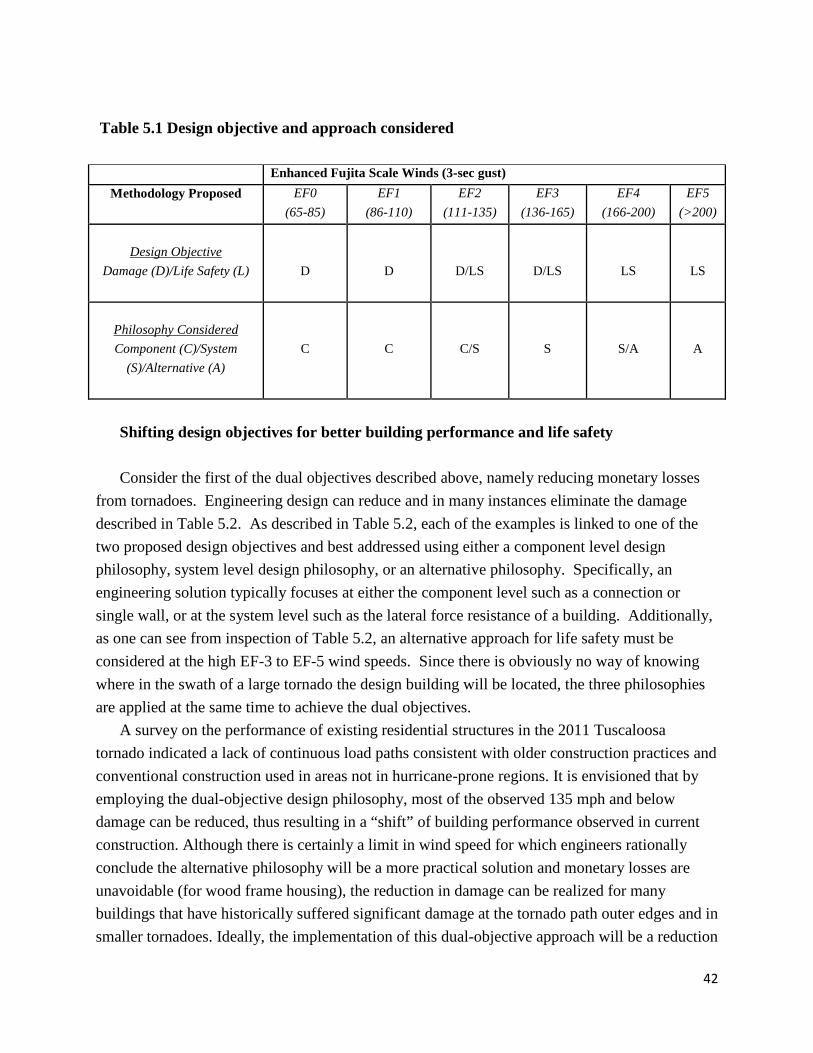
There are two considerations or design objectives for a new approach to engineering for tornadoes: damage (D) and life safety (L). Damage can be controlled at lower levels of the Enhanced Fujita (EF) scale wind speeds, i.e. EF0 and EF1, through the use of engineered connectors, design ensuring continuous vertical uplift load paths, and horizontal load distribution and load paths. This is handled typically at the component design level, i.e. connectors, single load paths. For wind speeds currently corresponding to EF2 and EF3 level damage, both component and system-level loading must be considered to enable better performance. System level performance is related to load sharing amongst wall lines and distribution of the lateral load path as a whole throughout the building as it is racked by wind and amplified further by windborne debris attacking a structure. In tornadoes with wind speeds currently corresponding to EF4 and EF5-level damage, the major issue becomes system effects and other alternatives to provide life safety to the building occupants. These alternatives are safe rooms, underground shelters, and often basements. Table 5.1 presents the concept of design objective and the philosophy aligning with each of the two objectives. It is important to note that the dual objectives must be used simultaneously in building design, and therefore so should the three philosophies that drive the design toward the objectives. This will ensure minimization of financial losses and protection of life safety for building occupants. Table 5.1:
42
Table 5.1 Design objective and approach considered and Philosophy Considered as a Function of Wind Speed Enhanced Fujita Scale Winds (3-sec gust)
Methodology Proposed EF0 (65-85)
EF1 (86-110)
EF2 (111-135)
EF3 (136-165)
EF4 (166-200)
EF5 (>200)
Design Objective
Damage (D)/Life Safety (L)
D
D
D/LS
D/LS
LS
LS
Philosophy Considered Component (C)/System
(S)/Alternative (A)
C
C
C/S
S
S/A
A
Shifting design objectives for better building performance and life safety
Consider the first of the dual objectives described above, namely reducing monetary losses
from tornadoes. Engineering design can reduce and in many instances eliminate the damage described in Table 5.2. As described in Table 5.2, each of the examples is linked to one of the two proposed design objectives and best addressed using either a component level design philosophy, system level design philosophy, or an alternative philosophy. Specifically, an engineering solution typically focuses at either the component level such as a connection or single wall, or at the system level such as the lateral force resistance of a building. Additionally, as one can see from inspection of Table 5.2, an alternative approach for life safety must be considered at the high EF-3 to EF-5 wind speeds. Since there is obviously no way of knowing where in the swath of a large tornado the design building will be located, the three philosophies are applied at the same time to achieve the dual objectives.
A survey on the performance of existing residential structures in the 2011 Tuscaloosa tornado indicated a lack of continuous load paths consistent with older construction practices and conventional construction used in areas not in hurricane-prone regions. It is envisioned that by employing the dual-objective design philosophy, most of the observed 135 mph and below damage can be reduced, thus resulting in a “shift” of building performance observed in current construction. Although there is certainly a limit in wind speed for which engineers rationally conclude the alternative philosophy will be a more practical solution and monetary losses are unavoidable (for wood frame housing), the reduction in damage can be realized for many buildings that have historically suffered significant damage at the tornado path outer edges and in smaller tornadoes. Ideally, the implementation of this dual-objective approach will be a reduction
43
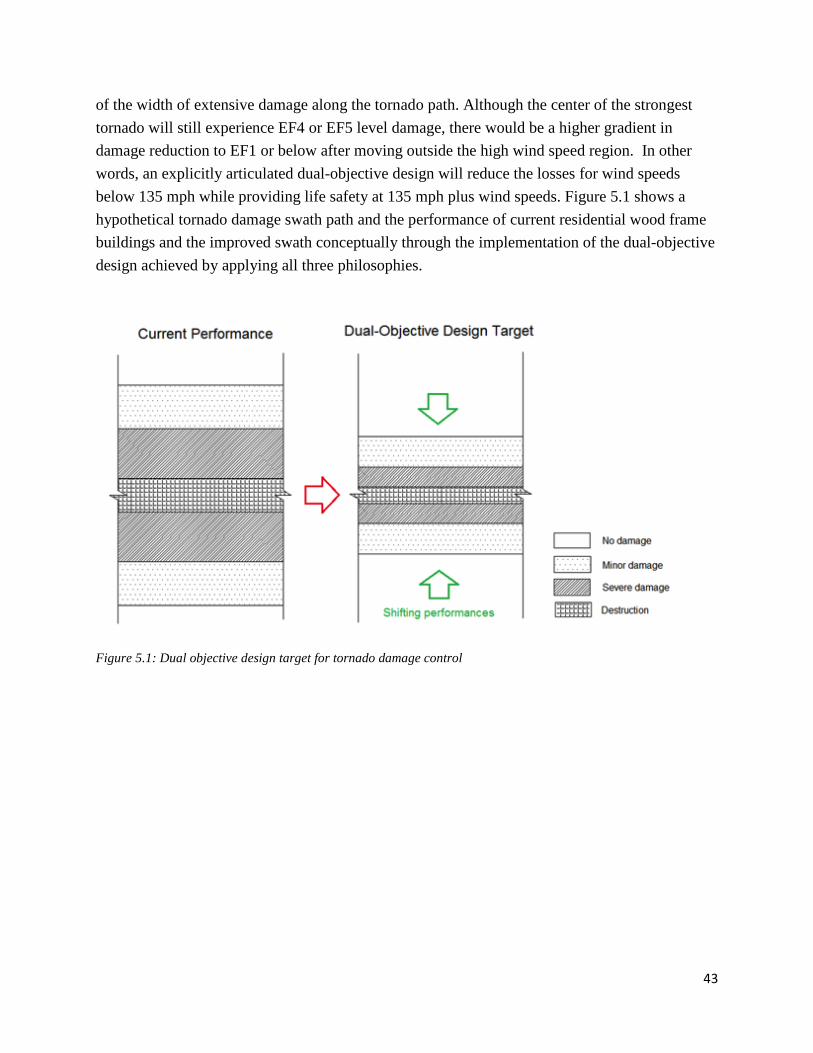
of the width of extensive damage along the tornado path. Although the center of the strongest tornado will still experience EF4 or EF5 level damage, there would be a higher gradient in damage reduction to EF1 or below after moving outside the high wind speed region. In other words, an explicitly articulated dual-objective design will reduce the losses for wind speeds below 135 mph while providing life safety at 135 mph plus wind speeds. Figure 5.1 shows a hypothetical tornado damage swath path and the performance of current residential wood frame buildings and the improved swath conceptually through the implementation of the dual-objective design achieved by applying all three philosophies.
Figure 5.1: Dual objective design target for tornado damage control

44
Table 5.2: Dual design objectives, philosophy, and examples of Engineering/Construction Improvements for Residential Construction Proposed
Design Objective
Philosophy
DOD1
Damage Description
Example Engineering and/or Construction
Improvements
Damage Mitigation
Component
1 Threshold of visible damage
N/A
2 Loss of roof covering Use manufacturer recommended number and placement of fasteners for high wind shingles.
2 Loss of vinyl/metal siding
Use high wind-rated siding and ensure fastener penetration into studs.
3 Broken glass in doors and windows
Use hurricane rated windows and doors. This is not necessarily effective against windborne debris impact, but minimizes loss of building envelope.
4 Uplift of roof deck and loss of significant roof covering material
Use hurricane clips on both sides of truss, 2x6 trusses, and heavier nail schedule on roof sheathing, add blocking for short edge nailing of roof sheathing.
4 Collapse of chimney Better connection to the structure and reinforcement in the chimney.
4 Garage door blown inward
High wind-rated garage door and track system.
Component /
System
4 Failure of porch or carport
Ensure continuous vertical load path through engineered metal connectors from roof into foundation.
5 House shifts off foundation
Ensure adequate number and placement of anchor bolts, use steel hold downs, 2x6 sill plates with square plate steel washers.
System
6 Large sections of roof structure removed
Ensure connection between trusses/rafters to wall top plates. Space trusses at 16” oc and line them up with vertical wall studs.
Life
Safety
7 Exterior walls collapsed
Closer nail schedule for shear capacity, provide full anchorage for all walls; safe room or shelter.
Alternative
8 Most walls collapsed Safe room or shelter. 9 All walls collapsed Safe room or shelter. 10 Slab swept clean Safe room or shelter.
1A recommendation for an Enhanced Fujita Scale (2006), Wind Science and Engineering Center, Texas Tech University, Lubbock, Texas.

45
In the following section, selected photos from the damage assessment are presented to illustrate several critical damage states outlined in Table 5.2. As illustrative examples, design and construction features that may help to shift the damage to a lower degree are discussed for each case, as well as the potential level of difficulty in addressing these problems with engineering design. DOD2: Loss of roof covering: May be due to aging of roofing material or improper fastener schedule. With high wind-rated roof shingles and correct installation details, there are numerous situations where the damage shown in Fig. 5.2 can be reduced or eliminated. Potential design difficulty: low DOD2: Loss of vinyl/metal siding: Siding materials are often torn off by strong wind due to their geometry and often installation details. The space between the siding and building envelop often makes it one of the first components to be damaged in strong wind, particularly siding on roof gables. Wind rated siding such as that used in Florida’s coast and proper installation, e.g. ensuring fastener penetration into studs and not OSB or sheathing material of any kind, can significantly increase the capacity of siding. Vinyl siding can get shredded with wind-borne debris in tornado wind fields. Potential design difficulty: Medium
Figure 5.2: Loss of roof covering
Figure 5.3 Loss of siding material

46
DOD3: Broken glass in doors and windows: The damage to doors and windows is difficult to design against, especially for a tornado because of the high debris content. There is no effective way to strengthen the entire building envelope to prevent missile intrusion; however, use of storm shutters may reduce windborne debris penetration for lower wind speeds (but likely not for wind speeds in excess of 140 mph). Another possible approach is to design the connections between building elements such as roofs to walls and walls to each other to resist separation at wind speeds less than 140 mph and provide improved interior wall connections to the floor and ceiling such that interior spaces could be safer from wind-borne debris. Potential design difficulty: High
DOD4: Uplift of roof deck and loss of significant roof covering material: Roof coverings are typically not designed for significant internal pressure which is almost always experienced by a tornado because of loss of building envelope as a result of window and door breakage. Specifying a design limit state in which internal pressure is considered and ensuring a continuous vertical load path are potential mitigation strategies. Potential design difficulty: Medium
Figure 5.4 Broken windows and doors
Figure 5.5 Significant roof damage
47
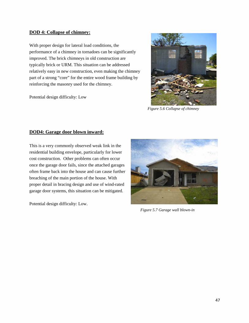
DOD 4: Collapse of chimney: With proper design for lateral load conditions, the performance of a chimney in tornadoes can be significantly improved. The brick chimneys in old construction are typically brick or URM. This situation can be addressed relatively easy in new construction, even making the chimney part of a strong “core” for the entire wood frame building by reinforcing the masonry used for the chimney. Potential design difficulty: Low DOD4: Garage door blown inward: This is a very commonly observed weak link in the residential building envelope, particularly for lower cost construction. Other problems can often occur once the garage door fails, since the attached garages often frame back into the house and can cause further breaching of the main portion of the house. With proper detail in bracing design and use of wind-rated garage door systems, this situation can be mitigated. Potential design difficulty: Low. Figure 5.7 Garage wall blown-in
Figure 5.6 Collapse of chimney
48
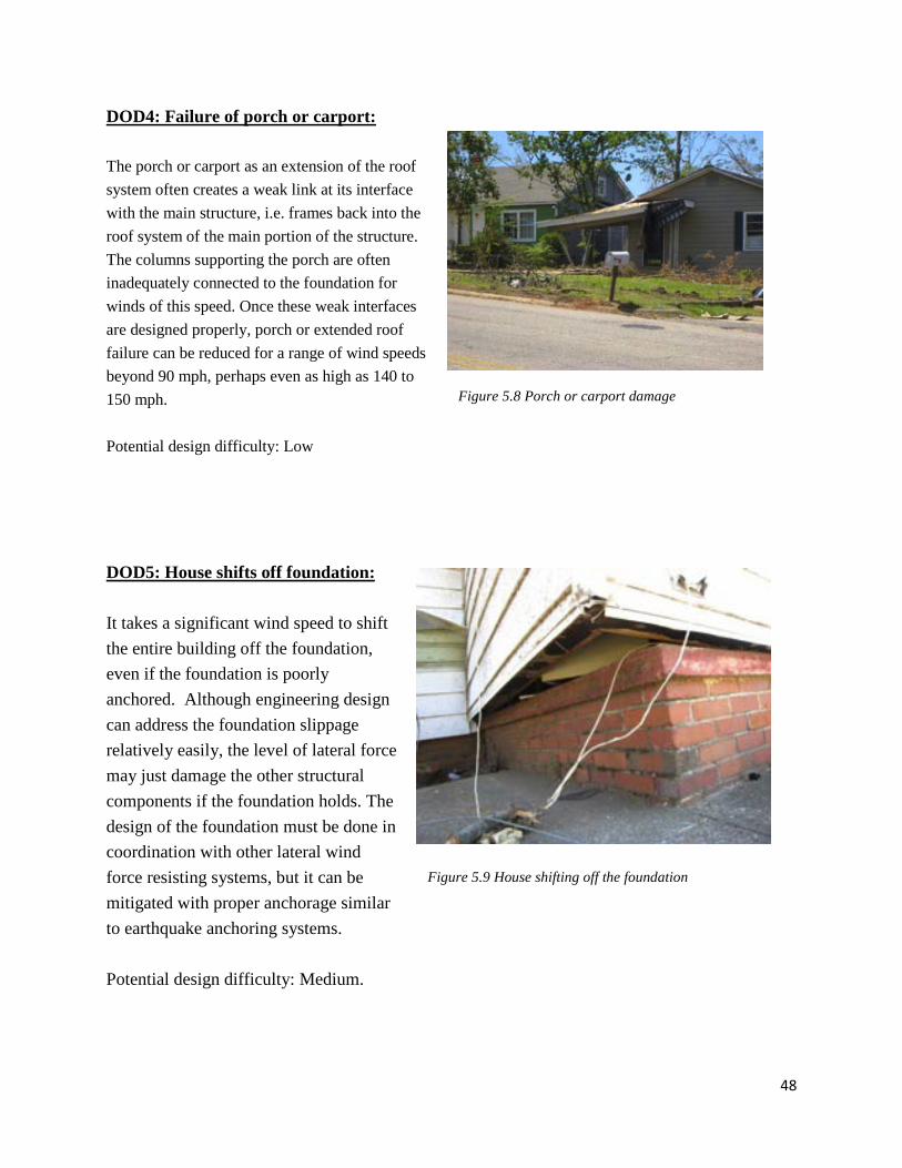
DOD4: Failure of porch or carport: The porch or carport as an extension of the roof system often creates a weak link at its interface with the main structure, i.e. frames back into the roof system of the main portion of the structure. The columns supporting the porch are often inadequately connected to the foundation for winds of this speed. Once these weak interfaces are designed properly, porch or extended roof failure can be reduced for a range of wind speeds beyond 90 mph, perhaps even as high as 140 to 150 mph. Potential design difficulty: Low DOD5: House shifts off foundation: It takes a significant wind speed to shift the entire building off the foundation, even if the foundation is poorly anchored. Although engineering design can address the foundation slippage relatively easily, the level of lateral force may just damage the other structural components if the foundation holds. The design of the foundation must be done in coordination with other lateral wind force resisting systems, but it can be mitigated with proper anchorage similar to earthquake anchoring systems. Potential design difficulty: Medium.
Figure 5.8 Porch or carport damage
Figure 5.9 House shifting off the foundation

49
DOD6: Large sections of roof structure removed: The failure of the majority of the roof structure may be mitigated through the use of connection hardware and non-conventional sizes for roof trusses. This may be a good practice for customized design or specific buildings. Due to the large uplift pressures on the roof, just improving the connection of the roof truss to the wall may not be sufficient. The roof ridge connections may also need to be strengthened so the roof does not come apart at the ridge.
Potential design difficulty: Medium DOD7: Exterior walls collapsed: A safe room or shelter is the best means of protecting the lives of the occupants in the event of wind speeds in excess of 160 mph. Potential design difficulty: High.
Figure 5.10 Large sections of roof removed
Figure 5.11 Exterior walls collapse

50
DOD8: Most walls collapsed:
A safe room or shelter is the best means of protecting the lives of the occupants in the event of wind speeds in excess of 160 mph.
DOD10: Slab swept clean: A safe room or shelter is the best means of protecting the lives of the occupants in the event of wind speeds in excess of 160 mph.
Figure 5.13 Slab swept clean in newer 2010 construction
Figure 5.12 Most walls collapsed

51
The low probability of tornado occurrence combined with its high consequences makes it a
very challenging load scenario to consider in structural design. Unlike straight winds, it is difficult to attach a specific probability to tornado wind speeds occurring at a specific building site. There are also studies (Sarkar et al., 2008) that show tornado loading has a significantly stronger vertical component than straight winds, even when the horizontal wind speeds are the same. Several critical issues need to be addressed before the structural engineering community can develop and implement a dual-objective design philosophy for tornado hazard mitigation. These are explained in the next chapter of this report.

52
CHAPTER 6 – CONCLUSIONS AND RECOMMENDATIONS Light-frame wood buildings do not, and will not, have the ability to resist EF4 or EF5 tornadoes. The Tuscaloosa tornado of 2011 was rated an EF4 tornado by the National Weather Service, and the authors of this report concur based on the method of rating a tornado at the strongest point along a touchdown path. Based on the information contained herein, and case studies not necessarily in this report but available on the web site http://esridev.caps.ua.edu/tuscaloosa_tornado/the following conclusions were reached:
1. The level of damage to light-frame wood buildings is not acceptable and can be reduced through new engineering design and construction practices.
2. The majority of residential buildings that suffer some level of damage in the path of a large tornado is caused by winds below the overall tornado EF rating assigned by the National Weather Service. Virtually all buildings in the path of a strong tornado, even along the outer edges where wind speeds are lower, are irreparable based on current design and construction practices. This provides incentive and an opportunity for tornado-resistant design and construction practices, which currently do not exist.
3. Damage to buildings on the outermost edges of the tornado appeared to be from inflow to the tornado vortex. This damage is mainly due to building penetration from debris strikes and wind speeds less than 130 mph. 4. Vertical load paths were not adequate, regardless of the age of the residential structure. Load paths appeared to be better provided on multi-family buildings. 5. Interior closets and bathrooms provide shelter at lower wind speeds on the edges of the tornado, but were no guarantee of survival. The concept of “safe spot” should still be taught, but a safe spot is not a substitute for a safe room or tornado shelter.
The following are the recommendations for further work on tornado loading of structures and mitigation of damage and loss of life:
1. Need to determine what tornado winds can be resisted with improved design and detailing. Identify realistic threshold wind speeds to address when trying to shift damage at the outer edges of a tornado, i.e. quantify the speeds at which certain failures occur so design strategies can be developed to prevent failure at those speeds. A systematic study needs to be conducted that

53
focuses on the optimal threshold tornado wind speed for which engineers should be designing a system.This requires a thorough survey of possible improvements and design options that are practical and the corresponding wind speed at which these measures will be valid. A study should also be conducted on the cost-benefit ratio of these design options at various wind speeds to inform the calibration of the new dual-objective tornado design philosophy. This threshold is highly dependent on the structure type. For wood-frame buildings it is likely to be in the 130~150 mph range.
2. Develop a better understanding of the spatial characteristics of tornado loading. The
current understanding of tornado loading on structures is not comprehensive or even comparable to that for straight strong winds because of the high level of turbulence and debris in a tornado. This is partially due to the lack of experimental procedures to accurately represent tornado loading. Unlike widely adopted scaled wind tunnel testing for wind loading on structures and components, it is very difficult to experimentally investigate the spatial characteristics of the loading on buildings within a tornado path. It is not clear how the lateral wind pressure and suction acts on different components of a structure, although some work has been performed on this issue (Sakar et al, 2008). Although applying design methods from straight wind cases will likely improve the resistance of buildings against tornadoes, designing using realistic and quantifiable tornado loading is most desirable. Studies in this topicshould be focused on scaled experimental work, numerical simulation, or in-situ tornado data collection.
3. Need acceptable and implementable approaches in design and construction to realize the damage reduction. A suite of design and retrofit measures should be developed to reduce structural and component damage up to the threshold wind speed. The measures for design and retrofit can be very different and may take many forms including adjustment factors for loading, prescriptive requirements, innovative analysis procedures, and additional load cases (such as the breached garage door case for attached garage wall and roof design). These measures must be backed by available products on the market that can be implemented by the current residential construction industry, possibly with minimal training. Implementing hurricane region construction practices and products in tornado-prone regions is a good starting point, but not necessarily an end solution.
4. Shelter inclusion for above threshold wind. For wind speeds exceeding the threshold, the alternatives of a shelter or safe room can provide life safety to building occupants. The shelter must be designed to handle both wind pressure and debris impact. The current guidelines (FEMA 320, FEMA 361 and ICC 500) to build safe rooms and shelters per FEMA or ICC recommendations can be adopted and enforced more for tornado prone regions. Shelters should

54
be included at the same time as the component and system philosophies are implemented as discussed above.

55
ACKNOWLEDGEMENTS The authors would like to acknowledge the U.S. National Science Foundation for their support through their RAPID grants program. The participation by Simpson Strong Tie and the Applied Technology Council is also acknowledged. The University of Alabama provided use of its facilities during the data analysis portion of the study. The content of this report solely reflects the views of the authors and not the National Science Foundation. The following students from several of the participating universities are also acknowledged for their contributions: UF: David Roueche UA: William Doherty, Pouria Bahmani, Giraj Kandukuri, Thang Dao, Alireza Geranmayeh, Guillermo Mejia-Aguilar

56
REFERENCES AISI S230-07 “Standard for Cold-formed Steel Framing – prescriptive Method for One- and
Two-Family Dwellings. ASCE; “ASCE 7-05: Minimum design Loads for Buildings and Other Structures:, Am. Soc.
Civil Engineers, Reston, VA Gurley, K., Davis, R., Ferrera, S-P, Burton, J. Masters, F., Reinhold, T., and Abdullah, M.
(2006). “Post 2004 Hurricane Field Survey – an Evaluation of the Relative Performance of the Standard Building Code and Florida Building Code.:, Proc ASCE Structures Congress, St Louis, Missouri.
Haan, F.L., Jr, V.K. Balaramudu, and P.P. Sarkar. (2010). “Tornado-Induced Wind Loads on a
Low-Rise Building”, Journal of Structural Engineering, 136(1), 106-116. ICC 600-08 “Standard for Residential Construction in High Wind Regions”, International Code
Council, Washington D.C. IRC (2009). International Residential Code for One- and Two-Family Dwellings, International
Code Council, Washington D.C. Shanmugam, B., Nielson, Bryant G., Prevatt, D.O., “Statistical and analytical models for roof
components in existing light-framed wood structures,” Engineering Structures Vol. 31, No. 11, (2009) 2607-2616.
Texas Tech (2006), A Recommendation for an Enhanced Fujita Scale, Wind Science and Engineering Center, Texas Tech University, Lubbock, Texas.
van de Lindt, J.W., A. Graettinger, R. Gupta, T. Skaggs, S. Pryor, and K. Fridley. (2007).
“Performance of Woodframe Structures During Hurricane Katrina.” ASCE Journal of Performance of Constructed Facilities; 21(2); 108-116.
WFCM-01 “ Wood Frame Construction Manual for One- and Two-family Dwellings,” American
Forest and Paper Association.