DAMAGE MECHANICS BASED APPROACH IN FAILURE...
37
DAMAGE MECHANICS BASED APPROACH IN FAILURE PREDICTION OF DRAW FORMING PROCESSES ISMAIL BIN ABU SHAH A thesis submitted in fulfilment of the requirements for the award of the degree of Doctor of Philosophy (Mechanical Engineering) Faculty of Mechanical Engineering Universiti Teknologi Malaysia JULY 2017
Transcript of DAMAGE MECHANICS BASED APPROACH IN FAILURE...
DAMAGE MECHANICS BASED APPROACH IN FAILURE PREDICTION OF
DRAW FORMING PROCESSES
ISMAIL BIN ABU SHAH
A thesis submitted in fulfilment of the
requirements for the award of the degree of
Doctor of Philosophy (Mechanical Engineering)
Faculty of Mechanical Engineering
Universiti Teknologi Malaysia
JULY 2017

iii
DEDICATION
To my beloved parents and family
iv
ACKNOWLEDGEMENT
Praise to the Almighty.
First and foremost, thanks to Allah s.w.t for the continuous blessing and for
giving me the strength and chances in completing this thesis. I would like to express
my heartfelt appreciation to my respectful supervisor, Prof. Dr. Mohd. Nasir Tamin
for his invaluable advice and supervision throughout this research.
Grateful acknowledgement is also made for financial support by the Ministry
of Higher Education (MOHE) Malaysia and Universiti Teknikal Malaysia Melaka.
This project is funded by the Ministry of Science, Technology and Innovation
(MOSTI) Malaysia and Universiti Teknologi Malaysia through Grant No.
TF0608C073-3H010 and RUG-00G42, respectively.
Apart from this, I am thankful to Computational Solid Mechanics Laboratory
(CSMLab) members who have shared valuable information, knowledge and thought
with me generously. It helps me to solve a lot of problems and difficulties. Their
constructive ideas and opinions are also making this research a success indirectly.
Finally yet importantly, further gratitude is forwarded to my beloved family
members and friends for their continuous supports and encouragements throughout
these years.
v
ABSTRACT
In a cup draw forming operation, the desired shape results from the material
hardening process under controlled plastic deformation and the springback
phenomena. In this study, a mechanics-of-deformation approach is developed based
on damage variables and large plastic deformation. The approach is then employed to
estimate the onset of the material damage event and the location of fracture based on
the mechanics response of the metal blank. Draw forming behavior of low carbon steel
is examined as a case study. The loading rate is conducted at a slow loading response
of the steels in the large deformation of the draw forming processes. Axisymmetric
and 3D solid models are developed for finite element (FE) simulations to gain insight
into the evolution of internal states and damage in the steel blanks during the draw
forming process. In the FE simulation, Johnson-Cook constitutive model with
isotropic hardening rule is employed. The Rice-Tracey ductile damage criterion is
employed to indicate damage initiation event along with a linear energy-displacement
relation for damage evolution rule. Results show that while the applied loading (tool
displacement) is quasi-static corresponding to the strain rate of 0.001 sec-1, the
maximum plastic strain rate at fracture could reach 100 times greater at the critical
material flow region. Failure of the deforming steel blank is localized with excessive
plastic deformation. While the onset of damage can be efficiently predicted using the
axisymmetric FE model with damage-based model, the subsequent damage evolution
of the localized ductile failure requires a 3D continuum FE model. The predicted tool
load-displacement response is employed in validating the FE model. Effects of
drawing parameters including drawing speed, blank holder force and die clearance on
the resulting deformation of the drawn cup-shape part are established. Based on the
response of the mechanics-of-deformation, the established
failure prediction approach is proven more accurate and reliable.
vi
ABSTRAK
Di dalam operasi pembentukan cawan, bentuk yang diinginkan terhasil
daripada proses pengerasan bahan di bawah fenomena tindakan ubah bentuk plastik
dan anjalan. Di dalam kajian ini, kaedah mekanik ubah bentuk dibangunkan
berdasarkan pemboleh ubah kerosakan dan ubah bentuk besar plastik. Kaedah ini
kemudiannya diguna pakai bagi menganggarkan permulaan kejadian kerosakan bahan
serta lokasi retakan berdasarkan tindak balas mekanik kepingan logam kosong. Sifat
pembentukan keluli berkarbon rendah adalah dikaji sebagai satu kajian kes. Muatan
ke besi dikenakan pada kadar tindak balas perlahan mengakibatkan perubahan besar
dalam proses penghasilan pembentukan. Model asimetrik dan model pepejal 3D
dibangunkan untuk simulasi unsur terhingga bagi mendapatkan pemahaman evolusi
keadaan dalaman dan kerosakan logam kosong semasa proses pembentukan tarikan.
Di dalam simulasi unsur terhingga, model menjuzuk Johnson-Cook bersama dengan
peraturan pengerasan isotrop adalah diguna pakai. Kriteria kerosakan mulur Rice-
Tracey digunakan bagi menunjukkan kejadian permulaan kerosakan berserta
hubungan linear tenaga dan sesaran untuk peraturan evolusi kerosakan. Hasil
menunjukkan walaupun laju alat yang dikenakan adalah pada kuasi-statik menurut
kadar terikan 0.001saat-1, kadar terikan retakan plastik tertinggi boleh mencecah 100
kali ganda di kawasan genting pengaliran bahan. Kerosakan oleh perubahan logam
kosong disetempatkan dengan lebihan ubah bentuk plastik. Sementara itu permulaan
kerosakan boleh di jangka dengan berkesan menggunakan model simulasi unsur
terhingga asimetrik menggunakan model berasaskan model kerosakan, evolusi
kerosakan seterusnya adalah kerosakan mulur setempat memerlukan model unsur
terhingga 3D. Jangkaan respon beban kepada sesaran digunakan bagi mengesahkan
model simulasi unsur terhingga. Kesan parameter penarikan termasuk kelajuan
penarikan, daya pemegang logam kosong dan kelegaan acuan tekan pada hasil ubah
bentuk oleh tertarik berbentuk cawan adalah tertubuh. Berdasarkan respon mekanik
ubah bentuk, pendekatan jangkaan kerosakan tertubuh dibuktikan
lebih tepat dan yakin.
vii
TABLE OF CONTENTS
CHAPTER TITLE PAGE
DECLARATION ii
DEDICATION iii
ACKNOWLEDGEMENT iv
ABSTRACT v
ABSTRAK vi
TABLE OF CONTENTS vii
LIST OF TABLES x
LIST OF FIGURES xi
LIST OF ABBREVIATIONS xvi
LIST OF SYMBOLS xvii
1 INTRODUCTION 1
1.1 Background of the Study 1
1.2 Statement of the Research Problem 3
1.3 Research Objectives 3
1.4 Scope of the Study 4
1.5 Significance of Study 4
1.6 Thesis Layout 5
2 LITERATURE REVIEW 7
2.1 Introduction 7
2.2 Trends in Sheet Metal Forming Processes 7
Automotive Steel Sheets 9
2.3 Formability in Draw Forming Processes 10
Forming Limit Diagram 11
2.4 Mechanics of Large Plastic Deformation 19
viii
2.5 Strain Rate Dependent Models 26
Johnson-Cook Model 27
2.6 Continuum Damage Mechanics 28
Damage Initiation Criterion 34
Damage Evolution Equation 36
2.7 Mechanisms of Failure 38
2.8 FE Simulation of Sheet Metal Forming Processes 42
2.9 Summary of Literature Review 49
3 RESEARCH METHODOLOGY 52
3.1 Introduction. 52
3.2 Research Framework 57
3.3 Demonstrator Material. 57
Material Properties 57
Properties and the Constitutive Model 59
Material Damage Model 62
3.4 Experimental Procedure. 64
Erichsen Cup Forming Machine 64
3.5 Finite Element Simulation of the Draw Forming Process 66
FE Circular Cup Draw Forming Model. 68
Mesh Convergence Study 72
Model Validation 74
3.6 Concluding Remarks 76
4 DEFORMATION AND FAILURE PROCESSES IN DRAW
FORMING OF A CIRCULAR CUP 77
4.1 Introduction 77
4.2 Mechanics Deformation 78
4.3 Effects of Blank Holder Force and Die Clearance Setting
on Deformation Processes 80
4.4 Evolution of Plastic Instability. 84
4.5 Fracture Location and Failure Mechanism 86
ix
4.6 Summary 88
5 SIMPLIFIED OF FE SIMULATION OF THE DRAW
FORMING PROCESS 89
5.1 Introduction 89
5.2 Characteristic of Stress and Strain Fields 89
5.3 Evolution of Plastic Instability 94
5.4 Failure Mechanics 98
5.7 Summary 98
6 FULL THREE DIMENSIONAL FE SIMULATION OF THE
DRAW FORMING PROCESS 100
6.1 Introduction 100
6.2 Fracture Location 100
6.3 Failure Mechanics 101
6.4 Damage Initiation 103
6.5 Damage Evolution 104
6.6 Stress and Strain Behavior 106
6.7 Characterization of Localized Thinning 107
6.8 Fracture Propagation Path 109
6.9 Summary 110
8 CONCLUSIONS & RECOMMENDATIONS 112
7.1 Conclusions 112
7.2 Recommendations 113
REFERENCES 114
Appendices A - B 126-127
x
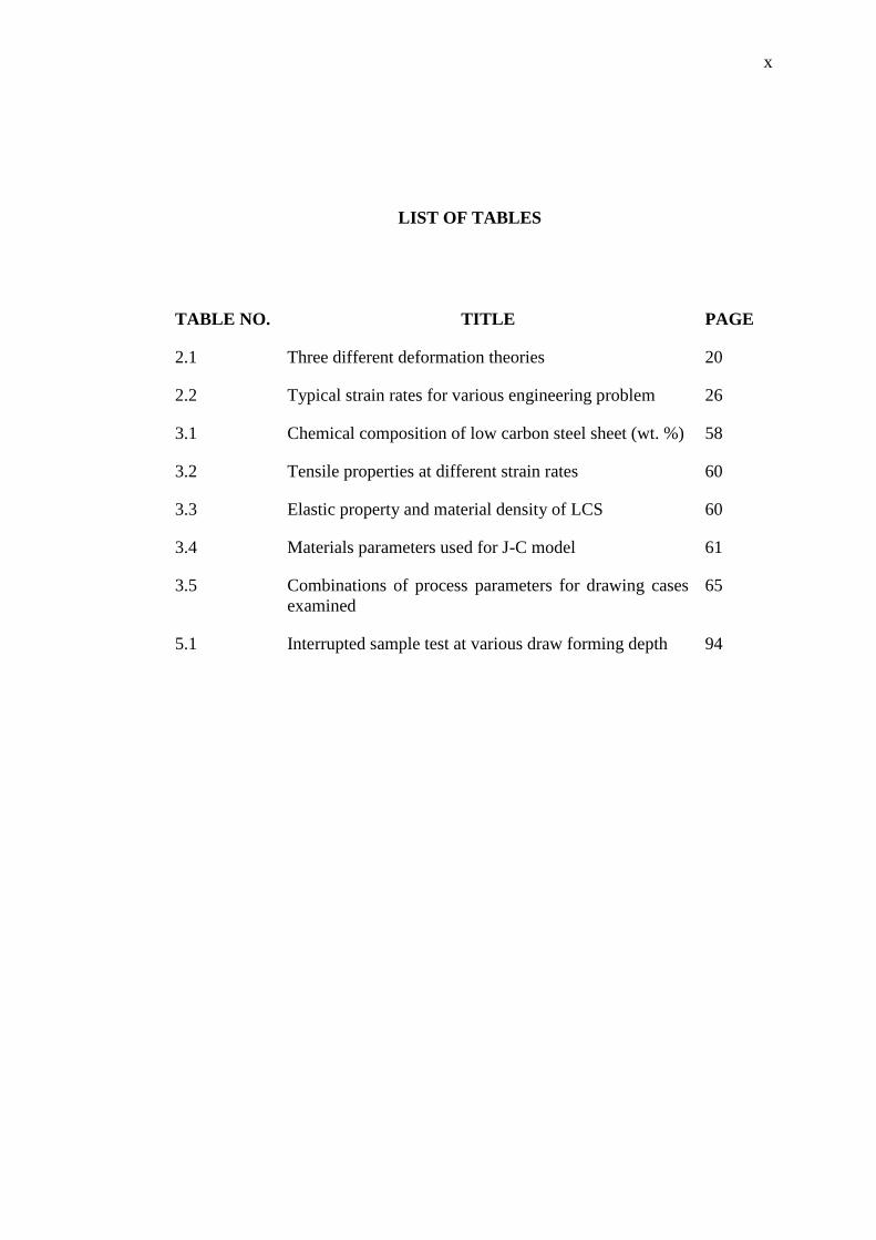
LIST OF TABLES
TABLE NO. TITLE PAGE
2.1 Three different deformation theories 20
2.2 Typical strain rates for various engineering problem 26
3.1 Chemical composition of low carbon steel sheet (wt. %) 58
3.2 Tensile properties at different strain rates 60
3.3 Elastic property and material density of LCS 60
3.4 Materials parameters used for J-C model 61
3.5 Combinations of process parameters for drawing cases
examined
65
5.1 Interrupted sample test at various draw forming depth 94
xi
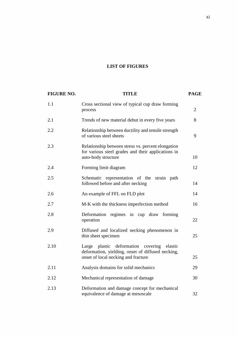
LIST OF FIGURES
FIGURE NO. TITLE PAGE
1.1 Cross sectional view of typical cup draw forming
process 2
2.1 Trends of new material debut in every five years 8
2.2 Relationship between ductility and tensile strength
of various steel sheets 9
2.3 Relationship between stress vs. percent elongation
for various steel grades and their applications in
auto-body structure 10
2.4 Forming limit diagram 12
2.5 Schematic representation of the strain path
followed before and after necking 14
2.6 An example of FFL on FLD plot 14
2.7 M-K with the thickness imperfection method 16
2.8 Deformation regimes in cup draw forming
operation 22
2.9 Diffused and localized necking phenomenon in
thin sheet specimen 25
2.10 Large plastic deformation covering elastic
deformation, yielding, onset of diffused necking,
onset of local necking and fracture 25
2.11 Analysis domains for solid mechanics 29
2.12 Mechanical representation of damage 30
2.13 Deformation and damage concept for mechanical
equivalence of damage at mesoscale 32
xii
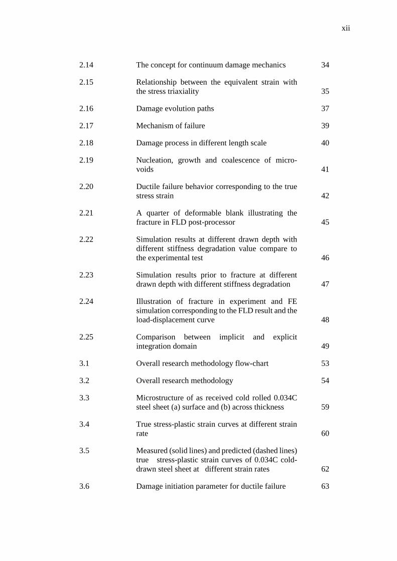
2.14 The concept for continuum damage mechanics 34
2.15 Relationship between the equivalent strain with
the stress triaxiality 35
2.16 Damage evolution paths 37
2.17 Mechanism of failure 39
2.18 Damage process in different length scale 40
2.19 Nucleation, growth and coalescence of micro-
voids 41
2.20 Ductile failure behavior corresponding to the true
stress strain 42
2.21 A quarter of deformable blank illustrating the
fracture in FLD post-processor 45
2.22 Simulation results at different drawn depth with
different stiffness degradation value compare to
the experimental test 46
2.23 Simulation results prior to fracture at different
drawn depth with different stiffness degradation 47
2.24 Illustration of fracture in experiment and FE
simulation corresponding to the FLD result and the
load-displacement curve 48
2.25 Comparison between implicit and explicit
integration domain 49
3.1 Overall research methodology flow-chart 53
3.2 Overall research methodology 54
3.3 Microstructure of as received cold rolled 0.034C
steel sheet (a) surface and (b) across thickness 59
3.4 True stress-plastic strain curves at different strain
rate 60
3.5 Measured (solid lines) and predicted (dashed lines)
true stress-plastic strain curves of 0.034C cold-
drawn steel sheet at different strain rates 62
3.6 Damage initiation parameter for ductile failure 63
xiii
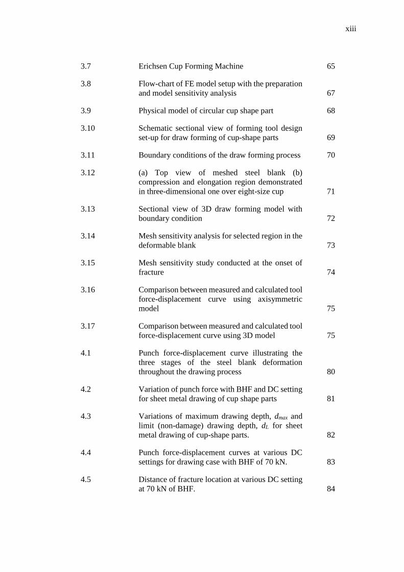
3.7 Erichsen Cup Forming Machine 65
3.8 Flow-chart of FE model setup with the preparation
and model sensitivity analysis 67
3.9 Physical model of circular cup shape part 68
3.10 Schematic sectional view of forming tool design
set-up for draw forming of cup-shape parts 69
3.11 Boundary conditions of the draw forming process 70
3.12 (a) Top view of meshed steel blank (b)
compression and elongation region demonstrated
in three-dimensional one over eight-size cup 71
3.13 Sectional view of 3D draw forming model with
boundary condition 72
3.14 Mesh sensitivity analysis for selected region in the
deformable blank 73
3.15 Mesh sensitivity study conducted at the onset of
fracture 74
3.16 Comparison between measured and calculated tool
force-displacement curve using axisymmetric
model 75
3.17 Comparison between measured and calculated tool
force-displacement curve using 3D model 75
4.1 Punch force-displacement curve illustrating the
three stages of the steel blank deformation
throughout the drawing process 80
4.2 Variation of punch force with BHF and DC setting
for sheet metal drawing of cup shape parts 81
4.3 Variations of maximum drawing depth, dmax and
limit (non-damage) drawing depth, dL for sheet
metal drawing of cup-shape parts. 82
4.4 Punch force-displacement curves at various DC
settings for drawing case with BHF of 70 kN. 83
4.5 Distance of fracture location at various DC setting
at 70 kN of BHF. 84
xiv
4.6 Progressive thickness variation across necking
band, shown at selected draw forming depth, case
A11. 85
4.7 Evolution of necking during sheet metal drawing
process for drawing case A11. 86
4.8 Fracture locations. 87
4.9 Fractured section of drawn cup for drawing case
A11. Inset figure shows enlargement of the
selected ductile failure area 87
4.10 Characteristic of fractured surface at different
BHF loading 88
5.1 (a) Equivalent stress at draw forming depth of 10.7
mm (b) residual stress, (c) residual strain 90
5.2 Plastic strain rate measured at various locations 91
5.3 Calculated strain rates at various location 93
5.4 Evolution of necking during the sheet metal
drawing process 95
5.5 Thinning section along the blank profile 96
5.6 The stress-strain behavior-along the profile 97
5.7 Comparison between FE and experimental test
with illustration of ductile failure. 98
6.1 Comparison between the simulated FE and
observed fracture location in the draw forming test 101
6.2 Comparison between FE and experimental draw
forming test 102
6.3 An element is separated from the cup sidewall at
the onset of fracture 103
6.4 Comparison between localized damage initiation
variable and the global load-displacement
response of the draw forming test 104
6.5 Degradation of critical element until it is separated 105
6.6 Characteristic of stress and strain evolution
throughout the draw forming process 106
xv
6.7 Simulation results at several drawn depths of the
interrupted draw forming 107
6.8 Comparison between FE simulations and
experimental test of thru-thickness evolution 108
6.9 Sectional view of fracture propagation from outer
to inner fiber at various draw forming depths 109
6.10 Crack propagation of fracture in biaxial direction
of fiber at different draw forming depth 110
xvi
LIST OF ABBREVIATIONS
AHSS - Advance High Strength Steel
BHF - Blank Holder Force
CAE - Computer Aided Engineering
CDM - Continuum Damage Mechanics
Cof - Coefficient of friction
C-S - Cowper- Symonds
DC - Die Clearance
DIC - Digital Image Correlation
FE - Finite Element
FFL - Fracture Forming Limit
FLC - Forming Limit Curve
FLD - Forming Limit Diagram
FLDF - Forming Limit Diagram at Fracture
FLDN - Forming Limit Diagram at Necking
GTN - Gurson–Tvergaard–Needleman
HER - Hole Expansion Ratio
J-C - Johnson-Cook
LCS - Low Carbon Steel
LDH - Limiting Dome Height
LDR - Limiting Drawing Ratio
R-K - Rusineck-Klapeczko
RVE - Representative Volume Element
SEM - Scanning Electron Microscope
TM - Tanimura-Mimura
Z-A - Zerilli-Armstrong
xvii
LIST OF SYMBOLS
A - Area
A’ - Johnson-Cook material constant
a - Material damage initiation parameters
B’ - Johnson-Cook strain hardening coefficient
C’ - Johnson-Cook strain rate sensitivity
c - Material damage initiation parameters
D - Damage variable
�̇� - Material constant
d - Drawing depth
di - Damage initiated
dL - Drawing limit
dmax - Maximum drawing depth
dA - Change of area
dF - Change of loading force
d𝜎 - Change of stress
d𝜀 - Change of strain
E - Young’s modulus
𝐸𝑜 - Young’s modulus of the material in the initial
undamaged state
𝐸𝐷 - Damaged state after loading
F - Force
Fmax - Maximum force
FL - Limit punch force
Gf - Fracture energy
L - Characteristic length of the element
m - Johnson-Cook temperature sensitivity
xviii
n - Johnson-Cook strain hardening
𝑇∗ - Johnson-Cook homologous temperature
Tmelt - Melting temperature
Troom - Room temperature
t - Thickness
tblank - Thickness of the blank
�̅�𝑝𝑙 - Equivalent plastic displacement
�̅�𝑓𝑝𝑙
- Equivalent plastic displacement at failure (damage
evolution)
ν - Poisson’s ratio
𝜔𝐷 - Internal state variable
Δ𝐴 - Apparent area (undamaged surface)
Δ�̃� - Changes the effective area
Δ𝐴𝑣𝑜𝑖𝑑 - Area with micro-voids
Δ𝐹 - External loading force
𝜎 - Equivalent stress
�̃� - Effective stress
𝜎𝑚 - Mean stress
𝜎𝑦 - Yield stress
𝜎𝑦𝑜 - Value of yield stress when damage criterion is met
𝜀 - Strain
𝜀̇ - Strain rate
𝜀̇∗ - Johnson-Cook dimensionless strain rate
𝜀0̇ - Johnson-Cook nominal strain rate
𝜀𝐷𝑝𝑙
- Effective plastic strain at the damage initiation
𝜀̅𝑝𝑙 - Equivalent plastic strain
𝜀0̅𝑝𝑙
- Effective plastic strain at the damage initiation
𝜀�̅�𝑝𝑙
- Effective plastic strain at fracture
𝜀�̅�𝑝 - Plastic strain rate at the onset of damage

xix
𝜀̅̇𝑝𝑙 - Equivalent plastic strain during the damage evolution
stage
𝜂 - Stress triaxiality
ρ - Material density
xx
LIST OF APPENDICES
APPENDIX. TITLE PAGE
A
B
Mesh quality index for axisymmetric model of
deformable blank.
Mesh quality index for 3D model of deformable
blank
126
127
CHAPTER 1
INTRODUCTION
1.1 Background of Study
Automotive body parts such as front quarter panel, suspension housing and
floor panel are produced through numerous metal forming processes. It is a process of
governing the formability of material into the desired shape throughout the forming
operation without fail [1]. In the classical shop floor approach, the well-known forming
limit diagram (FLD) is employed as a tool to predict the material failure in the metal
forming operation. It is practiced as an approach to prevent the occurrence of fracture
in sheet metal forming production.
In general, metal forming operation is divided into two main distinct processes,
which are cutting and shaping. The process of cutting such as blanking is a process of
separating the blank. While shaping for instance draw forming is to form the blank
into desired parts. As the main shaping metal forming process in the automotive
industries, the study of material failure concentrates on the draw forming operation.
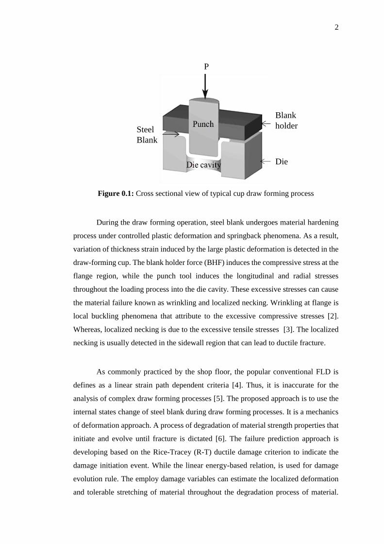
The typical tool and die movement are described thru the mechanism of the draw
forming process. The tool consists of a punch, blank holder and die cavity while steel
blank is employed as deformable parts as depicted in Figure 1.1. This monotonic
loading process of punch draws the steel blank into the die cavity at a specified drawing
depth and loading speed to draw forming shaped parts. The interactions between
deformable blank and forming tools induced large plastic deformation until it is
properly form into desired shape.
2
Figure 0.1: Cross sectional view of typical cup draw forming process
During the draw forming operation, steel blank undergoes material hardening
process under controlled plastic deformation and springback phenomena. As a result,
variation of thickness strain induced by the large plastic deformation is detected in the
draw-forming cup. The blank holder force (BHF) induces the compressive stress at the
flange region, while the punch tool induces the longitudinal and radial stresses
throughout the loading process into the die cavity. These excessive stresses can cause
the material failure known as wrinkling and localized necking. Wrinkling at flange is
local buckling phenomena that attribute to the excessive compressive stresses [2].
Whereas, localized necking is due to the excessive tensile stresses [3]. The localized
necking is usually detected in the sidewall region that can lead to ductile fracture.
As commonly practiced by the shop floor, the popular conventional FLD is
defines as a linear strain path dependent criteria [4]. Thus, it is inaccurate for the
analysis of complex draw forming processes [5]. The proposed approach is to use the
internal states change of steel blank during draw forming processes. It is a mechanics
of deformation approach. A process of degradation of material strength properties that
initiate and evolve until fracture is dictated [6]. The failure prediction approach is
developing based on the Rice-Tracey (R-T) ductile damage criterion to indicate the
damage initiation event. While the linear energy-based relation, is used for damage
evolution rule. The employ damage variables can estimate the localized deformation
and tolerable stretching of material throughout the degradation process of material.
Die
P
Blank
holderSteel
Blank
3
This mechanics of deformation approach is employ as a remedy to the problem in
material failure prediction. The mechanics of deformation is a branch of mechanics
that examine the behavior of material to the loading. It is an effort of investigating the
non-linear response in the material due to the changes in geometry and internal state
behavior throughout the draw forming operation.
1.2 Statement of the Research Problem
How could the mechanics of deformation approach employing damage model
and finite element (FE) simulation be used to predict material failure process in draw
forming operation.
1.3 Objectives
The aim of this study is to develop a damage-based failure prediction approach
on the mechanics of materials deformation. Specific objectives are:
1. To establish a validated framework for FE simulation of draw forming
processes.
2. To quantify the limitation of axisymmetric FE model for fracture.
3. To determine the effect of damage and its evolution on the material response.
4
1.4 Scope of Study
The present study covers the following scope of work:
1. Low carbon steel (LCS) is examined as a demonstrator material.
2. Erichsen cup forming machine is used to draw forming LCS into circular cup
shape parts.
3. The draw forming test is set at 1 mm/sec slow loading rates with constant BHF
to clamp uniformly on the flange part.
4. The FE simulations are carried out at strain rate dependent condition to model
the draw forming test.
5. Coulomb friction is applied in every interaction between forming tools and
deformable blank throughout the FE simulation.
6. Axisymmetric model with piecewise hardening curve is applied to define the
limitation of the geometrical representation of the model when predicting
failure.
7. Deformable blank in FE 3D circular cup is modeled using solid elements to
determine the thru thickness necking effect.
8. Johnson-Cook (J-C) isotropic hardening parameter incorporated with Rice-
Tracey (R-T) ductile damage initiation model and linear energy based model
are used to assess hardening and material failure respectively.
1.5 Significance of Study
In predicting material failure, FLD shows some disadvantageous which
requires new approach. Compared to the propose approach, its failure prediction
quality is considered as inaccurate for the complex analysis of draw forming processes.
This is due to its criteria that satisfy only for the linear strain path condition.
Furthermore, it is highly depending on the recorded experimental test data with less
mechanics based consideration. It is also very time consuming because it requires too
5
many data to be recorded with too many samples involved. As a result, these works
suffered high in cost.
On the other hand, the propose failure prediction approach not only able to
predict the onset of failure location accurately. Moreover, it is able to quantify the
internal states of material from the process of thru thickness necking throughout the
damage evolution until fracture. Therefore, the failure prediction results are more
realistic compared to classical shop floor approach.
With the advance in numerical simulation to compute virtually the draw
forming processes, the propose approach facilitates the assessment of deformation and
failure. It computes the mechanics of deformation throughout the formability of
material until the point of separation. Thru the understandings on mechanics of
deformation and failure processes, the behavior of tolerable stretching of the material
are define explicitly. It gives accurate and realistic physical representation of ductile
failure at a localized point in the material.
1.6 Thesis Layout
This thesis consists of seven chapters. In Chapter 1, the background and the
necessity of the background of the research are bringing out. The issues of material
failure in drawing automotive steel parts are based upon. The objectives, scope and
significance of the research are present.
In Chapter 2, reviews are presented on the trends in sheet metal forming
processes, automotive steel sheet, formability of draw forming processes, mechanics
of large plastic deformation, finite element, strain rate dependent models, continuum
damage mechanics, mechanism of failure, FE simulation of sheet metal forming
processes and summary of literature review.
6
In Chapter 3, the research methodology is present. The details of the applied
research materials, experimental setup and finite element (FE) simulation models are
explained.
In Chapter 4, the assessment of deformation and failure processes in draw
forming test are presented and discussed. Mechanics deformation of material
formability through the punch-force displacement curve is examined and interpreted.
Effects of BHF and DC setting in the process are measured. The interrupted draw
forming tests at different displacement depth are conducted. The evolution of plastic
instability in the interrupted draw-forming test is characterized. Fracture location and
failure mechanism is identified.
In Chapter 5, the application of FE simulation to assess the mechanics
deformation is addressed. An axisymmetric FE cup draw-forming model is used to
simulate the draw forming processes on LCS at uniform BHF. In modeling the
hardening behavior, piecewise plastic strain rate hardening parameter are employed.
The evolution of plastic instability in the interrupted draw forming simulation is
characterized. The calculated fracture location is compared.
In Chapter 6, the application of FE simulation to assess the damage mechanics
is address. Using 3D FE cup model, the damage mechanics are examined by
incorporating the J-C strain rate dependent criteria and damage variables until the
event of fracture. The calculated localized thinning is characterized and compared. The
fracture location in 3D FE cup model is demonstrated.
In Chapter 7, the major conclusions of the research are present. Future works
for refining the research are recommend.
REFERENCES
[1] W. C. Emmens, Formability. Berlin, Heidelberg: Springer Berlin Heidelberg,
2011.
[2] M. Kumar and A. Choudhary, “Plastic Wrinkling Investigation of Sheet Metal
Product Made by Deep Forming Process: A FEM Study,” Int. J. Eng. Res.
Technol., vol. 3, no. 10, pp. 186–191, 2014.
[3] S. Patil and R. G. Tated, “Formability Analysis for Trapezoidal Cup Forming
Using HyperForm,” Simul. Driven Innov., pp. 1–6, 2011.
[4] M. Abbasi, M. A. Shafaat, M. Ketabchi, D. F. Haghshenas, and M. Abbasi,
“Application of the GTN model to predict the forming limit diagram of IF-
Steel,” J. Mech. Sci. Technol., vol. 26, no. 2, pp. 345–352, 2012.
[5] S. J. Hashemi, H. M. Naeini, G. Liaghat, R. A. Tafti, and F. Rahmani, “Forming
limit diagram of aluminum AA6063 tubes at high temperatures by bulge tests,”
J. Mech. Sci. Technol., vol. 28, no. 11, pp. 4745–4752, 2014.
[6] S. Murakami, Continuum Damage Mechanics: Solid Mechanics and
Applications. Springer Berlin, 2012.
[7] F. H. Aboutalebi, M. Farzin, and M. Mashayekhi, “Numerical Predictions and
Experimental Validations of Ductile Damage Evolution,” Acta Mech. Solida
Sin., vol. 25, no. 6, pp. 638–650, 2012.
[8] O. J. Kwon, K. Y. Lee, G. S. Kim, and K. G. Chin, “New Trends in Advanced
High Strength Steel Developments for Automotive Application,” Mater. Sci.
Forum, vol. 638–642, pp. 136–141, 2010.
[9] Y. Abe, T. Ohmi, K. Mori, and T. Masuda, “Improvement of formability in deep
drawing of ultra-high strength steel sheets by coating of die,” J. Mater. Process.
Technol., vol. 214, no. 9, pp. 1838–1843, 2014.
[10] H. Hayashi and T. Nakagawa, “Recent trends in sheet metals and their
formability in manufacturing automotive panels,” J. Mater. Process. Technol.,
vol. 46, pp. 455–487, 1994.
117
[11] M. Tisza, “Recent development trends in sheet metal forming,” Int. J.
Microstruct. Mater. Prop., vol. 8, no. 1/2, p. 125, 2013.
[12] S. Coordinator and B. Sciences, “One day Symposium on Recent Trends and
Advances in Sheet Metal Forming 1 st December 2012 Organized by One day
Symposium on Recent Trends and Advances in Sheet Metal Forming Date :”
[13] E. Dias, L. Horimoto, and M. dos Santos Pereira, “Microstructural
Characterization of CP Steel Used in Automotive Industry,” Mater. Sci. Forum,
vol. 775–776, pp. 141–145, 2014.
[14] B. K. Zuidema, S. G. Denner, and B. Engl, “New High Strength Steels Applied
to the Body Structure of ULSB_AVC,” SAE, pp. 984–992, 2001.
[15] S. L. Costa, J. P. Mendonça, and N. Peixinho, “Study on the impact behaviour
of a new safety toe cap model made of ultra-high-strength steels,” Mater. Des.,
vol. 91, pp. 143–154, 2016.
[16] H. Tian, X. Liu, and J. Lin, “Investigation on the formability of tailor-welded
blanks,” vol. 97–101, pp. 260–263, 2010.
[17] S. Keeler, M. Kimchi, R. Kuziak, R. Kawalla, S. Waengler, and Y. G. Yuqing
Weng, Han Dong, “Advanced high strength steels for automotive industry,”
Arch. Civ. Mech. Eng., vol. 8, no. 2, p. 511, 2014.
[18] Formability: A Review of Parameters and Processes that Control, Limit or
Enhance the Formability of Sheet Metal, vol. 7. 2011.
[19] K. S. Prasad, T. Kamal, S. K. Panda, S. Kar, S. V. S. Narayana Murty, and S.
C. Sharma, “Finite Element Validation of Forming Limit Diagram of IN-718
Sheet Metal,” Mater. Today Proc., vol. 2, no. 4–5, pp. 2037–2045, 2015.
[20] M. C. Butuc, a. Barata da Rocha, J. J. Gracio, and J. Ferreira Duarte, “A more
general model for forming limit diagrams prediction,” J. Mater. Process.
Technol., vol. 125–126, pp. 213–218, 2002.
[21] M. Bhargava, A. Tewari, and S. K. Mishra, “Forming limit diagram of
Advanced High Strength Steels (AHSS) based on strain-path diagram,” Mater.
Des., vol. 85, pp. 149–155, 2015.
[22] H. Kuramae, Y. Ikeya, H. Sakamoto, H. Morimoto, and E. Nakamachi, “Multi-
scale parallel finite element analyses of LDH sheet formability tests based on
crystallographic homogenization method,” Int. J. Mech. Sci., vol. 52, no. 2, pp.
183–197, 2010.
118
[23] K. Bandyopadhyay, S. K. Panda, P. Saha, and G. Padmanabham, “Limiting
drawing ratio and deep drawing behavior of dual phase steel tailor welded
blanks: FE simulation and experimental validation,” J. Mater. Process.
Technol., vol. 217, pp. 48–64, 2015.
[24] W. Wu, P. Zhang, X. Zeng, L. Jin, S. Yao, and A. A. Luo, “Bendability of the
wrought magnesium alloy AM30 tubes using a rotary draw bender,” Mater. Sci.
Eng. A, vol. 486, no. 1–2, pp. 596–601, 2008.
[25] S. K. Paul, M. Mukherjee, S. Kundu, and S. Chandra, “Prediction of hole
expansion ratio for automotive grade steels,” Comput. Mater. Sci., vol. 89, pp.
189–197, 2014.
[26] F. Ozturk, M. Dilmec, M. Turkoz, R. E. Ece, and H. S. Halkaci, “Grid Marking
and Measurement Methods for Sheet Metal Formability,” 5th Int. Conf. Exhib.
Des. Prod. Mach. Dies/Molds, no. June, pp. 1–10, 2009.
[27] K. Wang, J. E. Carsley, B. He, J. Li, and L. Zhang, “Journal of Materials
Processing Technology Measuring forming limit strains with digital image
correlation analysis,” J. Mater. Process. Technol., vol. 214, pp. 1120–1130,
2014.
[28] H. J. Kim, S. C. Choi, K. T. Lee, and H. Y. Kim, “Experimental Determination
of Forming Limit Diagram and Springback Characteristics of AZ31B Mg Alloy
Sheets at Elevated Temperatures,” Mater. Trans., vol. 49, no. 5, pp. 1112–1119,
2008.
[29] H. W. Swift, “Plastic instability under plane stress,” J. Mech. Phys. Solid, vol.
1, pp. 1–18, 1952.
[30] R. Hill, “on Discontinuous Reference Plastic States , With Special To Localized
Necking in Thin Sheets,” vol. 1, pp. 19–30, 1952.
[31] L. Xue, “Localization conditions and diffused necking for damage plastic
solids,” Eng. Fract. Mech., vol. 77, no. 8, pp. 1275–1297, 2010.
[32] Y. Bouktir, H. Chalal, M. Haddad, and F. Abed-Meraim, “Investigation of
ductility limits based on bifurcation theory coupled with continuum damage
mechanics,” Mater. Des., vol. 90, pp. 969–978, 2016.
[33] M. B. Silva, A. J. Martínez-Donaire, G. Centeno, D. Morales-Palma, C.
Vallellano, and P. A. F. Martins, “Recent Approaches for the Determination of
Forming Limits by Necking and Fracture in Sheet Metal Forming,” Procedia
119
Eng., vol. 132, no. January 2016, pp. 342–349, 2015.
[34] J. M. Jalinier, “Calculation of the forming limit curve at fracture,” J. Mater.
Sci., vol. 18, no. 6, pp. 1794–1802, 1983.
[35] P. M. Parmar and P. Ashish, “Comparative Study of Forming Limit Diagram
for AISI 1020 Department of Mechanical ( Machine Design ),” vol. 3, no. 03,
pp. 2822–2825, 2015.
[36] D. Vysochinskiy, T. Coudert, O. S. Hopperstad, O. G. Lademo, and A. Reyes,
“Experimental detection of forming limit strains on samples with multiple local
necks,” J. Mater. Process. Technol., vol. 227, pp. 216–226, 2016.
[37] K. Isik, M. B. Silva, A. E. Tekkaya, and P. A. F. Martins, “Journal of Materials
Processing Technology Formability limits by fracture in sheet metal forming,”
J. Mater. Process. Tech., vol. 214, no. 8, pp. 1557–1565, 2014.
[38] M. He, F. Li, and Z. Wang, “Forming limit stress diagram prediction of
aluminum alloy 5052 based on GTN model parameters determined by in situ
tensile test,” Chinese J. Aeronaut., vol. 24, no. 3, pp. 378–386, 2011.
[39] H. Badreddine, C. Laberg??re, and K. Saanouni, “Ductile damage prediction in
sheet and bulk metal forming,” Comptes Rendus - Mec., vol. 344, no. 4–5, pp.
296–318, 2016.
[40] Z. Marciniak, K. Kuczyi, and S. K. I. Warsaw, “N _ N,” vol. 9, pp. 609–620,
1967.
[41] M. Nurcheshmeh and D. E. Green, “Prediction of sheet forming limits with
Marciniak and Kuczynski analysis using combined isotropicnonlinear
kinematic hardening,” Int. J. Mech. Sci., vol. 53, no. 2, pp. 145–153, 2011.
[42] J. Slota, “Comparison of the forming - limit diagram (FLD) models for drawing
quality (DQ) steel sheets,” Metalurgija, vol. 44, pp. 249–253, 2005.
[43] K. Takuda, H., Mori, K., Takakura, N., Yamaguchi, “Finite element analysis of
limit strain in biaxial stretching of sheet metals allowing ductile fracture,” Int.
J. Mech. Sci., vol. 42, pp. 785–798, 2000.
[44] D. Banabic, “A review on recent developments of Marciniak-Kuczynski
model,” Comput. Methods Mater. Sci., no. 1952, pp. 1–24, 2010.
[45] X. H. Hu, D. S. Wilkinson, M. Jain, P. D. Wu, and R. K. Mishra, “The impact
of particle distributions and grain-level inhomogeneities on post-necking
deformation and fracture in AA5754 sheet alloys during uniaxial tension,”
120
Mater. Sci. Eng. A, vol. 528, no. 4–5, pp. 2002–2016, 2011.
[46] L. Leotoing and D. Guines, “Investigations of the effect of strain path changes
on forming limit curves using an in-plane biaxial tensile test Investigations of
the effect of strain path changes on forming limit curves using an in-plane
biaxial tensile test,” vol. 99, pp. 21–28, 2015.
[47] F. Ozturk and D. Lee, “Analysis of forming limits using ductile fracture
criteria,” J. Mater. Process. Technol., vol. 147, no. 3, pp. 397–404, 2004.
[48] B. Li, T. J. Nye, and P. D. Wu, “Predicting the forming limit diagram of AA
5182-O,” J. Strain Anal. Eng. Des., vol. 45, no. 4, pp. 255–273, 2010.
[49] L. E. Bryhni D??hli, T. B??rvik, and O. S. Hopperstad, “Influence of loading
path on ductile fracture of tensile specimens made from aluminium alloys,” Int.
J. Solids Struct., vol. 88–89, pp. 17–34, 2016.
[50] F. A. McClintock, “A Criterion for Ductile Fracture by the Growth of Holes,”
J. Appl. Mech., vol. 35, no. 2, p. 363, 1968.
[51] J. R. Rice and D. M. Tracey, “On the ductile enlargement of voids in triaxial
stress fields,” J. Mech. Phys. Solids, vol. 17, no. 3, pp. 201–217, 1969.
[52] G. Vadillo, J. Reboul, and J. Fernández-Sáez, “A modified Gurson model to
account for the influence of the Lode parameter at high triaxialities,” Eur. J.
Mech. A/Solids, vol. 56, pp. 31–44, 2016.
[53] B. Ma, Z. G. Liu, Z. Jiang, X. Wu, K. Diao, and M. Wan, “Prediction of forming
limit in DP590 steel sheet forming: An extended fracture criterion,” Mater.
Des., vol. 96, pp. 401–408, 2016.
[54] M. V. Jr., P. A. Muñoz-Rojas, E. L. Cardoso, and M. Tomiyama,
“Considerations on parameter identification and material response for Gurson-
type and Lemaitre-type constitutive models,” Int. J. Mech. Sci., vol. 106, pp.
254–265, 2016.
[55] F. Xue, F. Li, B. Chen, J. Fan, and R. Wang, “A ductile-brittle fracture model
for material ductile damage in plastic deformation based on microvoid growth,”
Comput. Mater. Sci., vol. 65, pp. 182–192, 2012.
[56] V. Tvergaard, “Influence of Voids on Shear Band Instability Under Plane Strain
Conditions,” Int. J. Fract., vol. 17, no. 4, pp. 389–407, 1981.
[57] V. Tvergaard and A. Needleman, “Analysis of the Cup-Cone Round Tensile
Fracture,” Acta Metall., vol. 32, no. I, pp. 157–169, 1984.
121
[58] Z. Wang, A. Chapius, and Q. Liu, “Simulation of mechanical behavior of AZ31
magnesium alloy during twin-dominated large plastic deformation,” Trans.
Nonferrous Met. Soc. China, vol. 25, no. 11, pp. 3595–3603, 2015.
[59] D. Brokken, W. A. M. Brekelmans, and F. P. T. Baaijens, “Numerical modelling
of the metal blanking process,” J. Mater. Process. Technol., vol. 83, no. 83, pp.
192–199, 1998.
[60] V. Lemiale, J. Chambert, and P. Picart, “Description of numerical techniques
with the aim of predicting the sheet metal blanking process by FEM
simulation,” J. Mater. Process. Technol., vol. 209, no. 5, pp. 2723–2734, 2009.
[61] G. Eshel, M. Barash, and W. Johnson, “Rule based modeling for planning
axisymmetrical deep-drawing,” J. Mech. Work. Technol., vol. 14, no. 1, pp. 1–
115, 1986.
[62] V. Vorkov, R. Aerens, D. Vandepitte, and J. R. Duflou, “Springback prediction
of high-strength steels in large radius air bending using finite element modeling
approach,” Procedia Eng., vol. 81, no. October, pp. 1005–1010, 2014.
[63] E. H. Ouakdi, R. Louahdi, D. Khirani, and L. Tabourot, “Evaluation of
springback under the effect of holding force and die radius in a stretch bending
test,” Mater. Des., vol. 35, pp. 106–112, 2012.
[64] B. Logue, M. Dingle, and J. L. Duncan, “Side-wall thickness in draw die
forming,” J. Mater. Process. Technol., vol. 182, no. 1–3, pp. 191–194, 2007.
[65] D. Chang, “An analytical model of the ironing process including redundant
work effect,” vol. 75, pp. 253–258, 1998.
[66] S. Candra, I. M. L. Batan, W. Berata, and A. S. Pramono, “Analytical Study and
FEM Simulation of the Maximum Varying Blank Holder Force to Prevent
Cracking on Cylindrical Cup Deep Drawing,” Procedia CIRP, vol. 26, pp. 548–
553, 2015.
[67] L. Zhong-qin, W. Wu-rong, and C. Guan-long, “A new strategy to optimize
variable blank holder force towards improving the forming limits of aluminum
sheet metal forming,” J. Mater. Process. Technol., vol. 183, no. 2–3, pp. 339–
346, 2007.
[68] J. Chen, X. Zhou, and J. Chen, “Sheet metal forming limit prediction based on
plastic deformation energy,” J. Mater. Process. Technol., vol. 210, no. 2, pp.
315–322, 2010.
122
[69] K. Osakada, “History of plasticity and metal forming analysis,” J. Mater.
Process. Technol., vol. 210, no. 11, pp. 1436–1454, 2010.
[70] Y. Ling, “Uniaxial true stress-strain after necking,” AMP J. Technol., vol. 5, no.
1, pp. 37–48, 1996.
[71] J. Jeschke, D. Ostermann, and R. Krieg, “Critical strains and necking
phenomena for different steel sheet specimens under uniaxial loading,” Nucl.
Eng. Des., vol. 241, no. 6, pp. 2045–2052, 2011.
[72] Y. Bao and T. Wierzbicki, “On fracture locus in the equivalent strain and stress
triaxiality space,” Int. J. Mech. Sci., vol. 46, no. 1, pp. 81–98, 2004.
[73] G. Mirone, “A new model for the elastoplastic characterization and the stress-
strain determination on the necking section of a tensile specimen,” Int. J. Solids
Struct., vol. 41, no. 13, pp. 3545–3564, 2004.
[74] Z. L. Zhang, M. Hauge, J. Ødegård, and C. Thaulow, “Determining material
true stress–strain curve from tensile specimens with rectangular cross-section,”
Int. J. Solids Struct., vol. 36, no. 23, pp. 3497–3516, 1999.
[75] Sing C. Tang and Jwo Pan, Mechanics Modeling of Sheet Metal Forming. SAE
International, 2007.
[76] S. Tanimura, T. Tsuda, A. Abe, H. Hayashi, and N. Jones, “Comparison of Rate-
Dependent Constitutive Models with Experimental Data,” Int. J. Impact Eng.,
vol. 69, no. 0, pp. 104–113, 2014.
[77] M. Dunand, “Effect of strain rate on the ductile fracture of Advanced High
Strength Steel Sheets: Experiments and modeling,” vol. 56, p. 236, 2013.
[78] A. Reyes, O. S. Hopperstad, O. G. Lademo, and M. Langseth, “Modeling of
textured aluminum alloys used in a bumper system: Material tests and
characterization,” Comput. Mater. Sci., vol. 37, no. 3, pp. 246–268, 2006.
[79] S. K. Paul, A. Raj, P. Biswas, G. Manikandan, and R. K. Verma, “Tensile flow
behavior of ultra low carbon, low carbon and micro alloyed steel sheets for auto
application under low to intermediate strain rate,” Mater. Des., vol. 57, pp. 211–
217, 2014.
[80] I. Rohr, H. Nahme, and K. Thoma, “Material characterization and constitutive
modelling of ductile high strength steel for a wide range of strain rates,” Int. J.
Impact Eng., vol. 31, no. 4, pp. 401–433, 2005.
[81] G.R. Johnson and W.H. Cook, “A constitutive model and data for metals
123
subjected to large strains, high strain rates and high temperatures.pdf,” in
Proceedings of the Seventh Symposium on Ballistics, The Hague, The
Netherlands, 1983, pp. 541–547.
[82] L. Gambirasio and E. Rizzi, “An enhanced Johnson-Cook strength model for
splitting strain rate and temperature effects on lower yield stress and plastic
flow,” Comput. Mater. Sci., vol. 113, pp. 231–265, 2016.
[83] L. Gambirasio and E. Rizzi, “On the calibration strategies of the Johnson-Cook
strength model: Discussion and applications to experimental data,” Mater. Sci.
Eng. A, vol. 610, pp. 370–413, 2014.
[84] I. Irausquín, J. L. Pérez-Castellanos, V. Miranda, and F. Teixeira-Dias,
“Evaluation of the effect of the strain rate on the compressive response of a
closed-cell aluminium foam using the split Hopkinson pressure bar test,” Mater.
Des., vol. 47, pp. 698–705, 2013.
[85] F. Wang, J. Zhao, N. Zhu, and Z. Li, “A comparative study on Johnson-Cook
constitutive modeling for Ti-6Al-4V alloy using automated ball indentation
(ABI) technique,” J. Alloys Compd., vol. 633, pp. 220–228, 2015.
[86] R. J. Bhatt, “FLD Creation for SS304 Using Experiments and It ’ s Validation
Using HyperForm 11.0,” no. 1946, pp. 1–6.
[87] M. Turkoz, O. Yigit, M. Dilmec, and H. S. Halkaci, “Construction of Forming
Limit Diagram for AA 5754 and AA 2024 Aluminium Alloy,” in Proceedings
of the 12th International Conference on Aluminium Alloy, 2010, pp. 516–521.
[88] P. Teixeira, a. D. Santos, J. M. a. C. Sá, F. M. Andrade Pires, and a. B. Rocha,
“Sheet metal formability evaluation using continuous damage mechanics,” Int.
J. Mater. Form., vol. 2, no. S1, pp. 463–466, 2009.
[89] C. O. Arun, B. N. Rao, and S. M. Srinivasan, “Continuum damage growth
analysis using element free Galerkin method,” Sadhana - Acad. Proc. Eng. Sci.,
vol. 35, no. 3, pp. 279–301, 2010.
[90] M. N. Tamin and N. M. Shaffiar, Solder Joint Reliability Assessment: Finite
Element Simulation Methodology. Springer Science & Business, 2014.
[91] J. Lin, M. Mohamed, D. Balint, and T. Dean, “The development of continuum
damage mechanics-based theories for predicting forming limit diagrams for hot
stamping applications,” Int. J. Damage Mech., vol. 23, no. 5, pp. 684–701,
2013.
124
[92] F. H. Aboutalebi, M. Farzin, and M. Mashayekhi, “Numerical Predictions and
Experimental Validations of Ductile Damage Evolution,” Acta Mech. Solida
Sin., vol. 25, no. 6, pp. 638–650, 2012.
[93] Advances in Applied Mechanics, Volume 27. Academic Press, 1990.
[94] Y. Lou, H. Huh, S. Lim, and K. Pack, “New ductile fracture criterion for
prediction of fracture forming limit diagrams of sheet metals,” Int. J. Solids
Struct., vol. 49, no. 25, pp. 3605–3615, 2012.
[95] V. Uthaisangsuk, S. Muenstermann, U. Prahl, W. Bleck, H. P. Schmitz, and T.
Pretorius, “A study of microcrack formation in multiphase steel using
representative volume element and damage mechanics,” Comput. Mater. Sci.,
vol. 50, no. 4, pp. 1225–1232, 2011.
[96] Vuong Nguyen Van Do, “The Behavior of Ductile Damage Model on Steel
Structure Failure,” vol. 142, p. 8, 2016.
[97] J. Lian, H. Yang, N. Vajragupta, S. M??nstermann, and W. Bleck, “A method
to quantitatively upscale the damage initiation of dual-phase steels under
various stress states from microscale to macroscale,” Comput. Mater. Sci., vol.
94, no. C, pp. 245–257, 2014.
[98] L. Kang, H. Ge, and X. Fang, “An improved ductile fracture model for structural
steels considering effect of high stress triaxiality,” vol. 115, pp. 634–650, 2016.
[99] D. Chae and D. A. Koss, “Damage accumulation and failure of HSLA-100
steel,” Mater. Sci. Eng. A, vol. 366, no. 2, pp. 299–309, 2004.
[100] X. W. Chen, G. Chen, and F. J. Zhang, “Deformation and failure modes of soft
steel projectiles impacting harder steel targets at increasing velocity,” Exp.
Mech., vol. 48, no. 3, pp. 335–354, 2008.
[101] H. Hooputra, H. Gese, H. Dell, and H. Werner, “A comprehensive failure model
for crashworthiness simulation of aluminium extrusions,” Int. J.
Crashworthiness, vol. 9, no. 5, pp. 449–464, 2004.
[102] Y. Bao and T. Wierzbicki, “On the cut-off value of negative triaxiality for
fracture,” Eng. Fract. Mech., vol. 72, no. 7, pp. 1049–1069, 2005.
[103] Abaqus, Abaqus Analysis User’s Manual. Dassault Systemes Simulia Corp. RI,
2015.
[104] M. Kurumatani, K. Terada, J. Kato, T. Kyoya, and K. Kashiyama, “An isotropic
damage model based on fracture mechanics for concrete,” Eng. Fract. Mech.,
125
vol. 155, pp. 49–66, 2016.
[105] J. Lemaitre, “Coupled elasto-plasticity and damage constitutive equations,”
Comput. Methods Appl. Mech. Eng., vol. 51, pp. 31–49, 1985.
[106] L. Zybell, G. Hütter, T. Linse, U. Mühlich, and M. Kuna, “Size effects in ductile
failure of porous materials containing two populations of voids,” Eur. J. Mech.
A/Solids, vol. 45, pp. 8–19, 2014.
[107] M. J. Nemcko, J. Li, and D. S. Wilkinson, “Effects of void band orientation and
crystallographic anisotropy on void growth and coalescence,” vol. 95, pp. 270–
283, 2016.
[108] F. Liao, W. Wang, and Y. Chen, “Ductile fracture prediction for welded steel
connections under monotonic loading based on micromechanical fracture
criteria,” Eng. Struct., vol. 94, pp. 16–28, 2015.
[109] A. G. Leacock, “The Future of Sheet Metal Forming Research,” Mater. Manuf.
Process., vol. 27, no. 4, pp. 366–369, 2012.
[110] T.-C. Hsu and C.-H. Chu, “A finite-element analysis of sheet metal forming
processes,” J. Mater. Process. Technol., vol. 54, no. 1–4, pp. 70–75, 1995.
[111] S. Bruschi, T. Altan, D. Banabic, P. F. Bariani, A. Brosius, J. Cao, A. Ghiotti,
M. Khraisheh, M. Merklein, and A. E. Tekkaya, “Testing and modelling of
material behaviour and formability in sheet metal forming,” CIRP Ann. - Manuf.
Technol., vol. 63, no. 2, pp. 727–749, 2014.
[112] K. Roll, “Simulation of sheet metal forming - Necessary developments in the
future,” Numisheet 2008, no. September, pp. 59–68, 2008.
[113] W. Wang, Y. Zhao, Z. Wang, M. Hua, and X. Wei, “A study on variable friction
model in sheet metal forming with advanced high strength steels,” Tribol. Int.,
vol. 93, pp. 17–28, 2015.
[114] A. E. Tekkaya, “State-of-the-art of simulation of sheet metal forming,” J.
Mater. Process. Technol., vol. 103, no. 1, pp. 14–22, 2000.
[115] V. Diviné, E. Beauchesne, Q. Zeng, M. Istrate, S. Roy, A. D. France, D.
Renaissance, A. D. France, and D. Renaissance, “Failure Criteria for Stamping
Analysis in Radioss,” 2014.
[116] J. P. Fan, C. Y. Tang, C. P. Tsui, L. C. Chan, and T. C. Lee, “3D finite element
simulation of deep drawing with damage development,” Int. J. Mach. Tools
Manuf., vol. 46, no. 9, pp. 1035–1044, 2006.
126
[117] M. Khelifa, M. Oudjene, and A. Khennane, “Fracture in sheet metal forming:
Effect of ductile damage evolution,” Comput. Struct., vol. 85, no. 3–4, pp. 205–
212, 2007.
[118] M. Goelke, “Practical Aspects of Finite Element Simulation – A Student
Guide,” p. 453, 2012.
[119] P. Reddy, G. Reddy, and P. Prasad, “A Review on Finite Element Simulations
in Metal Forming,” Ijmer.Com, vol. 2, no. 4, pp. 2326–2330, 2012.
[120] K.-J. Bathe, “On the State of Finite Element Procedures for Forming
Processes,” Proc. 8th Int. Conf. Numer. Methods Ind. Form. Process., vol. 712,
pp. 34–38, 2004.
[121] T. Irie, S. Satoh, K. Hashiguchi, and I. Takahashi, “Metallurgical of Cold-rolled
Affecting Strength Steel Formability Sheets,” Trans. ISIJ, vol. 21, no. 793, pp.
793–801, 1981.
[122] Paul S. Gupton, “A Practical Approach to Understanding Steels, Their
Alloying, Heat Treatment and Surface Hardening,” in Proceedings of the
Fourteenth Turbomachinery Symposium, 1985, p. 103.
[123] S. S. Arsad, “Unified Constitutive Models for Deformation of Thin-Walled
Structures,” Universiti Teknologi Malaysia, 2012.
[124] M. N. Tamin, A. Abdul-Latif, A. Ayob, N. Kamsah, Y. Prawoto, Z. Ahmad, S.
Abdullah, and A. Desa, “Damage and Fracture Mechanics-Based Design
Methodology: Constitutive and Damage Modelsfor Steel Sheet Metals.,” in
Compatationally Optimised Fuel-Efficient Concept Car (Vol.1), 2011, p. 38.
[125] G. Fang*, P. Zeng, and L. Lou, “Finite element simulation of effect of part shape
on forming quality in fine-blanking process,” Procedia Eng., vol. 81, pp. 1108–
1113, 2014.
[126] N. S. Gokhale, Practical Finite Element Analysis. Finite To Infinite, 2008.
[127] G. C. M. Reddy, P. V. R. R. Reddy, and T. a. J. Reddy, “Finite element analysis
of the effect of coefficient of friction on the drawability,” Tribol. Int., vol. 43,
no. 5–6, pp. 1132–1137, 2010.
[128] W. M. Garrison and N. R. Moody, “Ductile fracture,” J. Phys. Chem. Solids,
vol. 48, no. 11, pp. 1035–1074, 1987.
[129] R. A. Lingbeek, T. Meinders, and A. Rietman, “Tool and blank interaction in
the cross-die forming process,” Int. J. Mater. Form., vol. 1, no. SUPPL. 1, pp.
127
161–164, 2008.
[130] A. Carpinteri, “Plastic flow collapse vs . separation collapse ( fracture ),”
Mat6riaux Constr., vol. 16, 1983.
[131] R. Neugebauer, K. D. Bouzakis, B. Denkena, F. Klocke, A. Sterzing, A. E.
Tekkaya, and R. Wertheim, “Velocity effects in metal forming and machining
processes,” CIRP Ann. - Manuf. Technol., vol. 60, no. 2, pp. 627–650, 2011.
[132] C. C. Tasan, J. P. M. Hoefnagels, C. H. L. J. ten Horn, and M. G. D. Geers,
“Experimental analysis of strain path dependent ductile damage mechanics and
forming limits,” Mech. Mater., vol. 41, no. 11, pp. 1264–1276, 2009.
[133] S. J. H. Z.T. Zhang, “Mathematical Modeling in Plane Strain Bending,” SAE
Tech. Pap., 1997.
[134] T. Zhang, K. Zhou, and Z. Q. Chen, “Strain rate effect on plastic deformation
of nanocrystalline copper investigated by molecular dynamics,” Mater. Sci.
Eng. A, vol. 648, pp. 23–30, 2015.
[135] U. S. Dixit, S. N. Joshi, and J. P. Davim, “Incorporation of material behavior in
modeling of metal forming and machining processes: A review,” Mater. Des.,
vol. 32, no. 7, pp. 3655–3670, 2011.
[136] D. Anderson, S. Winkler, A. Bardelcik, and M. J. Worswick, “Influence of
stress triaxiality and strain rate on the failure behavior of a dual-phase DP780
steel,” Mater. Des., vol. 60, pp. 198–207, 2014.
[137] M. K. and M. M. Rahman, “Fatigue Life Estimation Based on Continuum
Mechanics Theory with Application of Genetic Algorithm,” Int. J. Automot.
Mech. Eng., vol. 11, no. June, pp. 2586–2598, 2015.
[138] E. E. T. S. and E. C. C. G.M. Domínguez Almaraz, M. Guzmán Tapia, “Fatigue
life prediction based on macroscopic plastic zone on fracture surface of AISI-
SAE 1018 steel,” Int. J. Automot. Mech. Eng., vol. 1, pp. 29–37, Nov. 2010.
[139] K. Hariharan and C. Balaji, “Material optimization: A case study using sheet
metal-forming analysis,” J. Mater. Process. Technol., vol. 209, no. 1, pp. 324–
331, 2009.
[140] H. Jong, “International Journal of Mechanical Sciences. The forming limit
diagram of ferritic stainless steel sheets : Experiments and modeling,” vol. 64,
pp. 1–10, 2012.