Dam Safety Assessment of CCW Impoundments | US … waters are also discharged to these ponds. Fly...
33
Transcript of Dam Safety Assessment of CCW Impoundments | US … waters are also discharged to these ponds. Fly...


United States Environmental Protection AgencyWashington, DC
November 9, 2010
Dam Safety Assessment of CCW Impoundments
Rockport Power Plant
DRAFT REPORT
DRAFT REPORT
360° Engineering and Project Delivery Solutions
Dam Safety Assessment of CCW
Impoundments
Rockport Power Plant
ROBERT R. BOWERS, P.E. – VICE PRESIDENT
O’BRIEN & GERE ENGINEERS, INC.
Prepared for:
US Environmental Protection Agency
Washington, DC
13498/46122
TIM KRAUS, P.E.. – VICE PRESIDENT
O’BRIEN & GERE ENGINEERS, INC.

DAM SAFETY ASSESSMENT OF CCW IMPOUNDMENTS
ROCKPORT POWER PLANT
i | DRAFT: November 9, 2010
I:\US‐EPA.13498\46122.Assess‐Of‐Dam‐S\Docs\REPORTS\Rockport Power Plant\DRAFT REPORT\3 Assess Report_Rockport_DRAFT.doc
TABLE OF CONTENTS
1. Introduction ..................................................................................................................................................................................... 1
1.1. General ....................................................................................................................................................................................... 1
1.2. Project Purpose and Scope ................................................................................................................................................ 1
2. Project/Facility Description ...................................................................................................................................................... 3
2.1. General ....................................................................................................................................................................................... 3
2.2. Management Unit Description ......................................................................................................................................... 3
2.3. Hazard Potential Classification ........................................................................................................................................ 3
2.4. Impounding Structure Details ........................................................................................................................................... 4
2.4.1. Embankment Configuration .......................................................................................................................................... 4
2.4.2. Type of Materials Impounded ....................................................................................................................................... 4
2.4.3. Outlet Works ........................................................................................................................................................................ 4
3. Records Review .............................................................................................................................................................................. 5
3.1. Engineering Documents ...................................................................................................................................................... 6
3.1.1. Stormwater Inflows .......................................................................................................................................................... 6
3.1.2. Stability Analyses ............................................................................................................................................................... 6
3.1.3. Instrumentation .................................................................................................................................................................. 7
3.2. Previous Inspections ............................................................................................................................................................ 7
3.3. Operator Interviews ............................................................................................................................................................. 7
4. Visual Inspection ............................................................................................................................................................................ 8
4.1. General ....................................................................................................................................................................................... 8
4.2. Summary of Findings ........................................................................................................................................................... 8
5. Conclusions ...................................................................................................................................................................................... 9
6. Recommendations ...................................................................................................................................................................... 10
6.1. Urgent Action Items ........................................................................................................................................................... 10
6.2. Long Term Improvement ................................................................................................................................................ 10
6.3. Monitoring and Future Inspection .............................................................................................................................. 10
6.4. Time Frame for Completion of Repairs/Improvements .................................................................................... 10
6.5. Certification Statement .................................................................................................................................................... 10

DAM SAFETY ASSESSMENT OF CCW IMPOUNDMENTS
ROCKPORT POWER PLANT
ii | DRAFT: November 9, 2010
I:\US‐EPA.13498\46122.Assess‐Of‐Dam‐S\Docs\REPORTS\Rockport Power Plant\DRAFT REPORT\3 Assess Report_Rockport_DRAFT.doc
Figures Figure 1 – Site Location Map Figure 2 – Facility Layout Plan Figure 3 – Photo Location Plan: Bottom Ash Complex Appendices Appendix A – Visual Inspection Checklist Appendix B – Photo Log: Bottom Ash Complex

DAM SAFETY ASSESSMENT OF CCW IMPOUNDMENTS
ROCKPORT POWER PLANT
1 | DRAFT: November 9, 2010
I:\US‐EPA.13498\46122.Assess‐Of‐Dam‐S\Docs\REPORTS\Rockport Power Plant\DRAFT REPORT\3 Assess Report_Rockport_DRAFT.doc
1. INTRODUCTION 1.1. GENERAL In response to the coal combustion waste (CCW) impoundment failure at the TVA/Kingston coal‐fired electric generating station in December of 2008, the U. S. Environmental Protection Agency (USEPA) has initiated a nationwide program of structural integrity and safety assessments of coal combustion waste impoundments or “management units”. A CCW management unit is defined as a surface impoundment or similar diked or bermed management unit or management units designated as landfills that receive liquid‐borne material and are used for the storage or disposal of residuals or by‐products from the combustion of coal, including, but not limited to, fly ash, bottom ash, boiler slag, or flue gas emission control residuals. Management units also include inactive impoundments that have not been formally closed in compliance with applicable federal or state closure/reclamation regulations. The USEPA has authorized O’Brien & Gere to provide site specific impoundment assessments at selected facilities. This project is being conducted in accordance with the terms of BPA# EP10W000673, Order No. EP‐CALL‐0002, dated July 28, 2010. 1.2. PROJECT PURPOSE AND SCOPE The purpose of this work is to provide dam safety assessment of CCW management units, including the following: Identify conditions that may adversely affect the structural stability and functionality of a management unit
and its appurtenant structures Note the extent of deterioration, status of maintenance, and/or need for immediate repair Evaluate conformity with current design and construction practices Determine the hazard potential classification for units not currently classified by the management unit
owner or by state or federal agencies O’Brien & Gere’s scope of services for this project includes performing a site specific dam safety assessment of all CCW management units at the subject facility. Specifically, the scope includes the following tasks: Perform a review of pertinent records (prior inspections, engineering reports, drawings, etc.) made
available at the time of the site visit to review previously documented conditions and safety issues and gain an understanding of the original design and modifications of the facility.
Perform a site visit and visual inspection of each CCW management unit and complete the visual inspection checklist to document conditions observed.
Perform an evaluation of the adequacy of the outlet works, structural stability, quality and adequacy of the management unit’s inspection, maintenance, and operations procedures.
Identify critical infrastructure within 5 miles downstream of management units. Evaluate the risks and effects of potential overtopping and evaluate effects of flood loading on the
management units. Provide immediate notification of conditions requiring emergency or urgent corrective action. Identify all environmental permits issued for the management units. Identify all leaks, spills, or releases of any kind from the management units within the last 5 years. Prepare a report summarizing the findings of the assessment, conclusions regarding the safety and
structural integrity, recommendations for maintenance and corrective action, and other action items as appropriate.
This report addresses the above issues for the Bottom Ash Complex at the AEP Indiana Michigan Power (I&M) Rockport Power Plant in the Town of Rockport, Spencer County, Indiana. The above impoundment is owned and

DAM SAFETY ASSESSMENT OF CCW IMPOUNDMENTS
ROCKPORT POWER PLANT
2 | DRAFT: November 9, 2010
I:\US‐EPA.13498\46122.Assess‐Of‐Dam‐S\Docs\REPORTS\Rockport Power Plant\DRAFT REPORT\3 Assess Report_Rockport_DRAFT.doc
operated by I&M. In the course of this assessment, we obtained information through interviews with representatives of AEP and I&M.

DAM SAFETY ASSESSMENT OF CCW IMPOUNDMENTS
ROCKPORT POWER PLANT
3 | DRAFT: November 9, 2010
I:\US‐EPA.13498\46122.Assess‐Of‐Dam‐S\Docs\REPORTS\Rockport Power Plant\DRAFT REPORT\3 Assess Report_Rockport_DRAFT.doc
2. PROJECT/FACILITY DESCRIPTION 2.1. GENERAL The Rockport Power Plant is located at 791 N US Highway 231, Rockport, IN 47635‐8883. A Site Location Map is included as Figure 1. The plant operates two coal fired generating units rated at 1,300 megawatts (MW) each. Unit 1 and Unit 2 were placed in service in 1984, and 1989, respectively. A Facility Layout Plan is included as Figure 2. Coal combustion waste that is produced during power generation is managed on‐site with a CCW impoundment. The facility utilizes six contiguous and hydraulically connected impoundments or cells known as the Bottom Ash Complex (BAC) for CCW management. The cells are separated by internal divider dikes. The individual cells of the BAC are identified as follows:
East Bottom Ash Pond West Bottom Ash Pond East Wastewater Pond West Wastewater Pond Reclaim Pond Clearwater Pond
2.2. MANAGEMENT UNIT DESCRIPTION The six contiguous impoundments that make up the BAC and inspected during this safety assessment are identified on Figure 3. None of the impoundments are regulated as dams by the Indiana Department of Natural Resources (IDNR). The BAC was designed by internal power company engineers with technical consultation provided by Casagrande & Associates. The Bottom Ash Complex was constructed in the late 1970’s and commissioned in 1981. The BAC has not been modified significantly since original construction. CCW that is managed in the impoundments consists of bottom ash only. Fly ash is removed by electrostatic precipitators and placed in dry storage or taken off‐site for beneficial use. Bottom ash generated at the Rockport Plant is hydraulically sluiced to either the East or West Bottom Ash Pond, depending on which pond is actively receiving sluiced bottom ash. After a significant amount of bottom ash is collected in the active pond, the sluice flows are re‐directed to the adjacent pond and the “full” pond is dewatered. Upon dewatering, the accumulated bottom ash is pushed by bulldozer or loader into a stockpile located at the north end of the Bottom Ash Pond. The stockpiled bottom ash is trucked off‐site for beneficial re‐use. Water in the Bottom Ash Ponds flows into the Wastewater Ponds for further suspended solids removal. From there, water enters the Reclaim Pond where the water is pumped back to the plant to be re‐used for CCW sluicing. Water flows into the Clearwater Pond for final “polishing” prior to discharging over a fixed weir outlet into a 66‐inch CMP pipe, which outfalls into the Ohio River. The final discharge is permitted under NPDES # IN 0051845. 2.3. HAZARD POTENTIAL CLASSIFICATION Based on correspondence from AEP I&M in a response letter to US EPA regarding a request for information, the Bottom Ash Complex is not currently regulated by the State of Indiana Department of Natural Resources, Division of Water. In addition, the Bottom Ash Complex is not listed on the National Inventory of Dams. As such, no hazard classifications have been assigned to the CCW impoundments by any state or federal dam safety agency.

DAM SAFETY ASSESSMENT OF CCW IMPOUNDMENTS
ROCKPORT POWER PLANT
4 | DRAFT: November 9, 2010
I:\US‐EPA.13498\46122.Assess‐Of‐Dam‐S\Docs\REPORTS\Rockport Power Plant\DRAFT REPORT\3 Assess Report_Rockport_DRAFT.doc
The definitions for the four hazard potential classifications (Less than Low, Low, Significant and High) to be used in this assessment are included in the EPA CCW checklist found in Appendix A. Based on the checklist definitions and as a result of this assessment, the hazard potential rating recommended for the Bottom Ash Complex at Rockport Power Plant is LOW. This classification is recommended in consideration of the low height (about 13 ft.) of the only impounding dike along the west side of the Bottom Ash Complex and the wide, flat, undeveloped buffer zone downstream of the west dike. Failure is unlikely to result in loss of human life, or damage to critical infrastructure. Environmental losses would likely be minor, given that the impoundment is about ½ mile from the Ohio River. Land inundated by a potential dike breach would likely be limited to farmland.
2.4. IMPOUNDING STRUCTURE DETAILS
As described previously, the Bottom Ash Complex consists of six contiguous impoundments separated by internal divider dikes. The following sections summarize the structural components and basic operations of the BAC. The locations of these features at the Rockport Plant are shown on Figure 3 along with Photograph location and orientation identifiers. The corresponding Photographic Log of selected photographs taken during the inspection is provided as Appendix B.
2.4.1. Embankment Configuration
The BAC is a combined incised/diked earthen embankment impoundment with a total surface area of approximately 137 acres and a design storage capacity of approximately 1,640 acre‐feet. The BAC is divided into 6 contiguous cells separated by internal earthen divider dikes. The outer perimeter of the BAC is diked on only the west side of the West Bottom Ash Pond cell. The west dike has a maximum height from crest to outboard toe of about 13 feet. All other sides of the BAC are incised below surrounding grades. The crest of the west dike is 30 feet wide at EL 399 along the West Bottom Ash Pond cell. The inboard and outboard slopes were constructed at 2 horizontal to 1 vertical (2H:1V) and 2.5H:1V, respectively. The outer west dike and internal dikes were constructed of natural clayey soils excavated from the interior of the ponds. The impoundment was not designed with an engineered liner system. Riprap armoring is present along the inboard slopes of the cells.
2.4.2. Type of Materials Impounded
Currently, influent into the BAC includes water with solids consisting of bottom ash only. Other plant non‐CCW waste waters are also discharged to these ponds. Fly ash is removed from the emissions by electrostatic precipitators and placed in dry storage or taken off‐site for beneficial use.
2.4.3. Outlet Works The six cells of the BAC are hydraulically linked by several discharge structures that control the flow of water from the influent pipes at the north end of the BAC to the final outlet structure at the west side of the Clearwater Pond. The East and West Bottom Ash Ponds have both surface water adjustable weir outlet structures and low‐level outlet structures for dewatering the ponds. Water flows over a fixed weir from the East and West Wastewater Ponds to a center hub structure that directs the flow into the Reclaim Pond or the Clearwater Pond. Water in the Reclaim Pond is taken into the pump house on the east side, then recirculated back to the plant. Flows between the Reclaim Pond and the Clearwater Pond are controlled by a zero slope equalization pipe at EL 385 feet and a low level outlet that can be used to dewater the Reclaim Pond into the Clearwater Pond. The outlet structure for the Clearwater Pond consists of a long concrete decanting weir that directs overflow to a drop inlet box. The permitted outfall to the Ohio River flows from the drop inlet box into a 66‐inch corrugated metal pipe. The pipe extends about ½ mile from the Clearwater Pond to the river.
DAM SAFETY ASSESSMENT OF CCW IMPOUNDMENTS
ROCKPORT POWER PLANT
5 | DRAFT: November 9, 2010
I:\US‐EPA.13498\46122.Assess‐Of‐Dam‐S\Docs\REPORTS\Rockport Power Plant\DRAFT REPORT\3 Assess Report_Rockport_DRAFT.doc
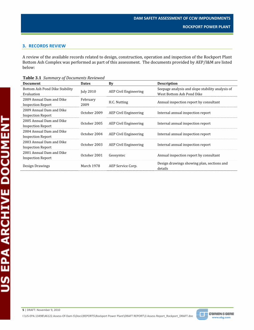
3. RECORDS REVIEW A review of the available records related to design, construction, operation and inspection of the Rockport Plant Bottom Ash Complex was performed as part of this assessment. The documents provided by AEP/I&M are listed below: Table 3.1 Summary of Documents Reviewed
Document Dates By Description Bottom Ash Pond Dike Stability Evaluation
July 2010 AEP Civil Engineering Seepage analysis and slope stability analysis of West Bottom Ash Pond Dike
2009 Annual Dam and Dike Inspection Report
February 2009
H.C. Nutting Annual inspection report by consultant
2009 Annual Dam and Dike Inspection Report
October 2009 AEP Civil Engineering Internal annual inspection report
2005 Annual Dam and Dike Inspection Report
October 2005 AEP Civil Engineering Internal annual inspection report
2004 Annual Dam and Dike Inspection Report
October 2004 AEP Civil Engineering Internal annual inspection report
2003 Annual Dam and Dike Inspection Report
October 2003 AEP Civil Engineering Internal annual inspection report
2001 Annual Dam and Dike Inspection Report
October 2001 Geosyntec Annual inspection report by consultant
Design Drawings March 1978 AEP Service Corp. Design drawings showing plan, sections and details

DAM SAFETY ASSESSMENT OF CCW IMPOUNDMENTS
ROCKPORT POWER PLANT
6 | DRAFT: November 9, 2010
I:\US‐EPA.13498\46122.Assess‐Of‐Dam‐S\Docs\REPORTS\Rockport Power Plant\DRAFT REPORT\3 Assess Report_Rockport_DRAFT.doc
3.1. ENGINEERING DOCUMENTS Review of the documents and drawings revealed information on the design details for the Bottom Ash Complex and the west dike of the Bottom Ash Pond which is summarized below: The Bottom Ash Complex was commissioned in 1981. The general soil profile at the BAC site consisted of 5 to 15 feet of stiff to hard clay, underlain by silty sand. Native clayey soils excavated to form the incised ponds were used to construct the internal dikes and outer
west dike. Due to the low permeability of the clayey native soils, the impoundments were designed without a liner. The internal dikes were constructed with slopes at 2H:1V. The inboard and outboard slopes of the outer
west dike were constructed at 2H:1V and 2.5H:1V, respectively. The BAC has not been modified significantly from its original design The annual inspection reports reviewed identified only minor deficiencies such as high vegetation, minor
erosion, and corrosion of structural steel members of the outlet structure access platforms and railings. No significant dam safety issues such as seepage, slope sloughing, settlement, etc. were mentioned in the annual inspection reports reviewed.
No history of past slope failures, sloughing, cracking or other earth dike distress was indicated in the documents reviewed.
No evidence or history of past releases due to perimeter dike failures or outlet structure failures was indicated in the documents reviewed.
No evidence of dike construction over existing ash foundation or other unsuitable materials was indicated in the documents reviewed.
3.1.1. Stormwater Inflows Stormwater inflows to the BAC are minimal and generally limited to precipitation which falls directly on the BAC itself. The impounding structure is comprised of a dike on a portion of the west side, with a crest elevation above the surrounding grades. The other three sides of the BAC are surrounded by relatively flat land that is at similar grade or lower than the “crest” of the outer dikes. In addition, ditches are in place to collect stormwater runoff and route it away from the BAC. The maximum operating water levels, synonymous with normal or maximum storage pool, of the six cells of the BAC provide a minimum of 3 feet of freeboard such that direct precipitation that falls on the impoundment will not cause it to overtop its dikes. 3.1.2. Stability Analyses In the absence of a design phase slope stability analysis of the west dike of the West Bottom Ash Pond, AEP Civil Engineering completed a slope stability analysis in 2010. The stability analysis methods appear to have been performed in general accordance with U.S. Army Corps of Engineers (USACE) Slope Stability Engineer Manual EM 1110‐2‐1902. A critical section was selected along the western dike where the embankment is at its maximum elevation. The computer software SLOPE/W was used to evaluate the factor of safety of the upstream and downstream slopes of the west dike. The soil strength parameters applied in the slope stability model were estimated from the design geotechnical report by Casagrande & Associates. The location of the phreatic surface through the embankment was based on a steady‐state seepage analysis using hydraulic conductivity values presented in the design geotechnical report for the embankment soils and the clay foundation. Load cases analyzed for the outboard slope included: steady‐state seepage at maximum operation pool, and steady‐state seepage with seismic load at maximum operating pool. Rapid drawdown analysis of the inboard slope was also
DAM SAFETY ASSESSMENT OF CCW IMPOUNDMENTS
ROCKPORT POWER PLANT
7 | DRAFT: November 9, 2010
I:\US‐EPA.13498\46122.Assess‐Of‐Dam‐S\Docs\REPORTS\Rockport Power Plant\DRAFT REPORT\3 Assess Report_Rockport_DRAFT.doc
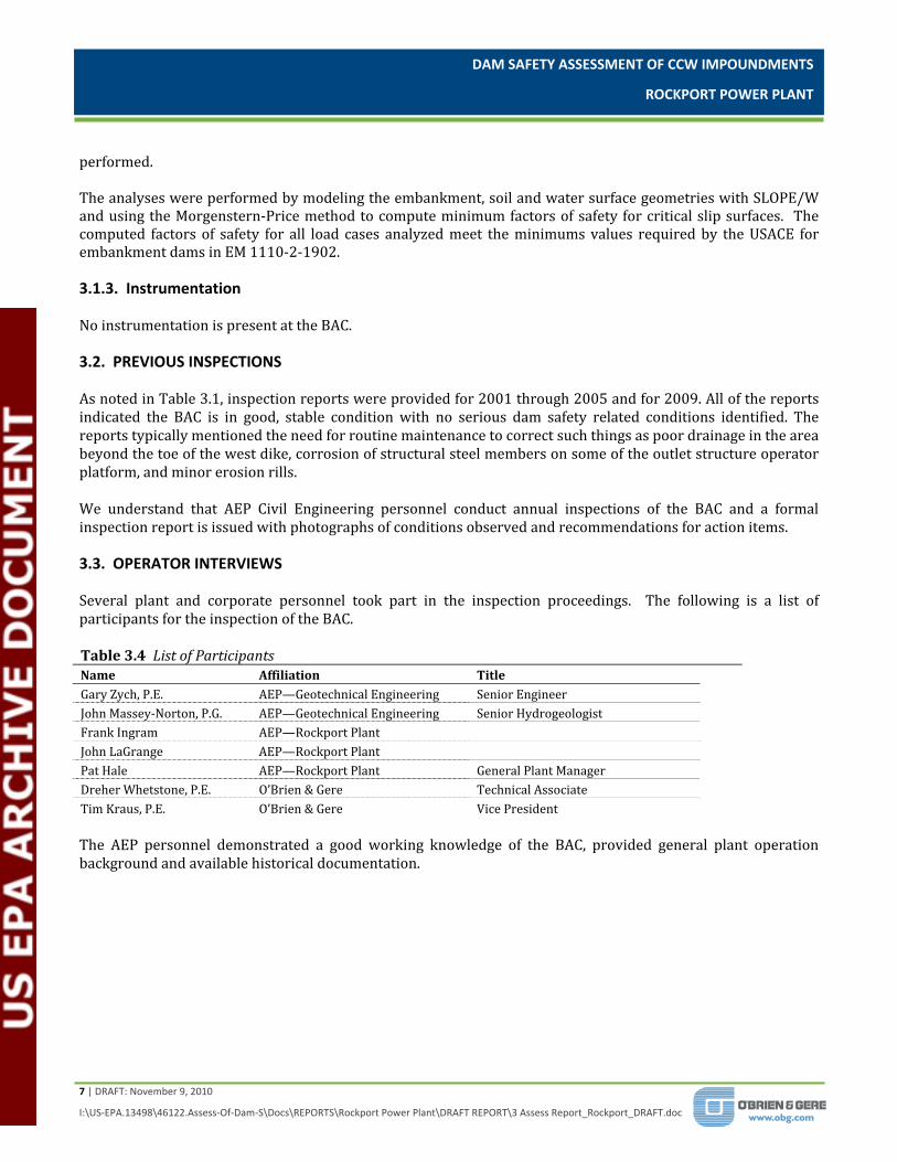
performed. The analyses were performed by modeling the embankment, soil and water surface geometries with SLOPE/W and using the Morgenstern‐Price method to compute minimum factors of safety for critical slip surfaces. The computed factors of safety for all load cases analyzed meet the minimums values required by the USACE for embankment dams in EM 1110‐2‐1902. 3.1.3. Instrumentation No instrumentation is present at the BAC. 3.2. PREVIOUS INSPECTIONS As noted in Table 3.1, inspection reports were provided for 2001 through 2005 and for 2009. All of the reports indicated the BAC is in good, stable condition with no serious dam safety related conditions identified. The reports typically mentioned the need for routine maintenance to correct such things as poor drainage in the area beyond the toe of the west dike, corrosion of structural steel members on some of the outlet structure operator platform, and minor erosion rills. We understand that AEP Civil Engineering personnel conduct annual inspections of the BAC and a formal inspection report is issued with photographs of conditions observed and recommendations for action items. 3.3. OPERATOR INTERVIEWS Several plant and corporate personnel took part in the inspection proceedings. The following is a list of participants for the inspection of the BAC. Table 3.4 List of Participants Name Affiliation Title Gary Zych, P.E. AEP—Geotechnical Engineering Senior Engineer John Massey‐Norton, P.G. AEP—Geotechnical Engineering Senior Hydrogeologist Frank Ingram AEP—Rockport Plant John LaGrange AEP—Rockport Plant Pat Hale AEP—Rockport Plant General Plant Manager Dreher Whetstone, P.E. O’Brien & Gere Technical Associate Tim Kraus, P.E. O’Brien & Gere Vice President The AEP personnel demonstrated a good working knowledge of the BAC, provided general plant operation background and available historical documentation.
DAM SAFETY ASSESSMENT OF CCW IMPOUNDMENTS
ROCKPORT POWER PLANT
8 | DRAFT: November 9, 2010
I:\US‐EPA.13498\46122.Assess‐Of‐Dam‐S\Docs\REPORTS\Rockport Power Plant\DRAFT REPORT\3 Assess Report_Rockport_DRAFT.doc
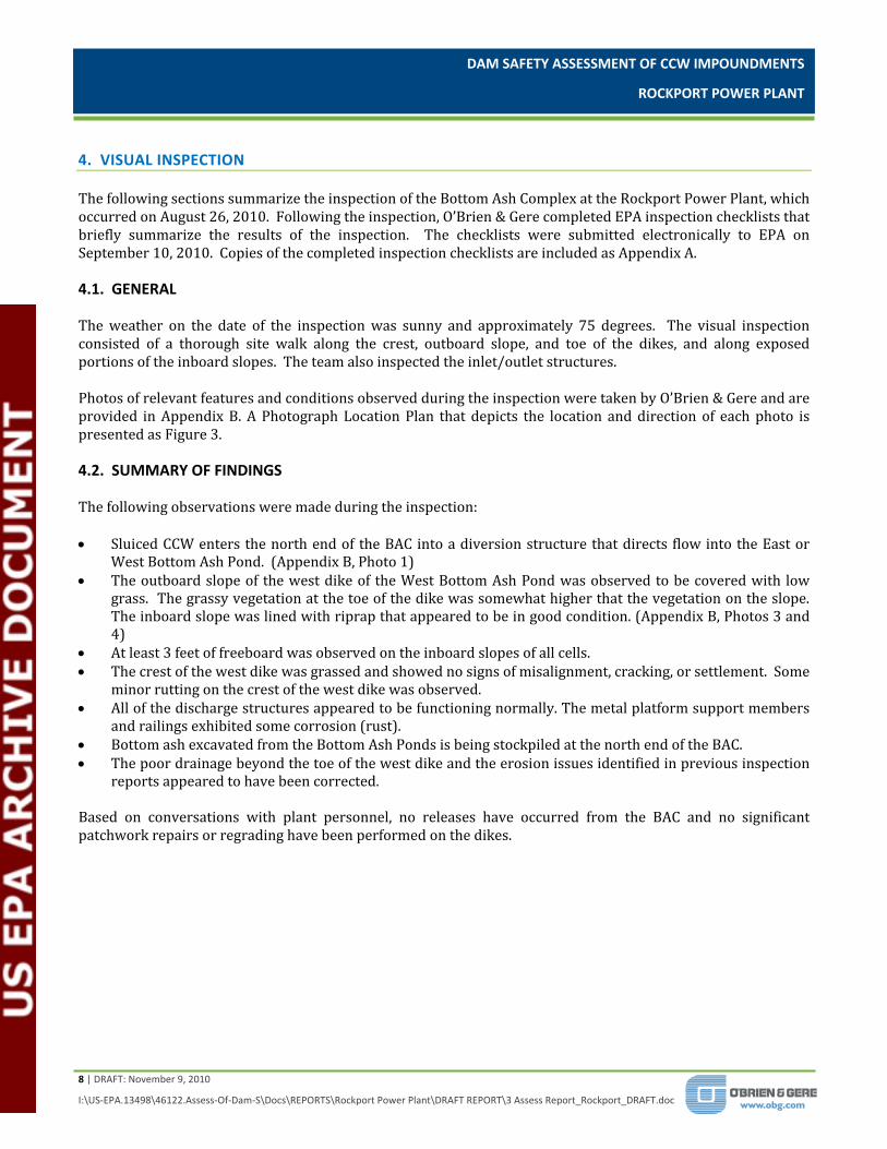
4. VISUAL INSPECTION The following sections summarize the inspection of the Bottom Ash Complex at the Rockport Power Plant, which occurred on August 26, 2010. Following the inspection, O’Brien & Gere completed EPA inspection checklists that briefly summarize the results of the inspection. The checklists were submitted electronically to EPA on September 10, 2010. Copies of the completed inspection checklists are included as Appendix A. 4.1. GENERAL The weather on the date of the inspection was sunny and approximately 75 degrees. The visual inspection consisted of a thorough site walk along the crest, outboard slope, and toe of the dikes, and along exposed portions of the inboard slopes. The team also inspected the inlet/outlet structures. Photos of relevant features and conditions observed during the inspection were taken by O’Brien & Gere and are provided in Appendix B. A Photograph Location Plan that depicts the location and direction of each photo is presented as Figure 3. 4.2. SUMMARY OF FINDINGS The following observations were made during the inspection: Sluiced CCW enters the north end of the BAC into a diversion structure that directs flow into the East or
West Bottom Ash Pond. (Appendix B, Photo 1) The outboard slope of the west dike of the West Bottom Ash Pond was observed to be covered with low
grass. The grassy vegetation at the toe of the dike was somewhat higher that the vegetation on the slope. The inboard slope was lined with riprap that appeared to be in good condition. (Appendix B, Photos 3 and 4)
At least 3 feet of freeboard was observed on the inboard slopes of all cells. The crest of the west dike was grassed and showed no signs of misalignment, cracking, or settlement. Some
minor rutting on the crest of the west dike was observed. All of the discharge structures appeared to be functioning normally. The metal platform support members
and railings exhibited some corrosion (rust). Bottom ash excavated from the Bottom Ash Ponds is being stockpiled at the north end of the BAC. The poor drainage beyond the toe of the west dike and the erosion issues identified in previous inspection
reports appeared to have been corrected. Based on conversations with plant personnel, no releases have occurred from the BAC and no significant patchwork repairs or regrading have been performed on the dikes.

DAM SAFETY ASSESSMENT OF CCW IMPOUNDMENTS
ROCKPORT POWER PLANT
9 | DRAFT: November 9, 2010
I:\US‐EPA.13498\46122.Assess‐Of‐Dam‐S\Docs\REPORTS\Rockport Power Plant\DRAFT REPORT\3 Assess Report_Rockport_DRAFT.doc
5. CONCLUSIONS Based on the ratings defined in the USEPA Task Order Performance Work Statement (Satisfactory, Fair, Poor and Unsatisfactory), the information reviewed and the visual inspection, the overall condition of the BAC impoundment is as follows: The Bottom Ash Complex is considered to be in SATISFACTORY condition. No conditions were observed that represent an existing or potential dam safety deficiency. Acceptable performance is expected under all applicable loading conditions in accordance with the applicable criteria. A few minor maintenance needs were identified. Plant engineering personnel responsible for the operation and maintenance of the impoundment indicated in interviews that a regular operations and maintenance procedure is in place at the BAC. The regular operating procedures for managing water levels in the cells do not appear to be impacting the structural integrity of the impounding embankments. The regular maintenance procedures appear to be adequate. The facility’s engineering staff maintain all design documents and inspection reports in a well organized manner. The plant’s operations personnel make daily “drive‐by” observations to monitor general conditions of the impoundment and also perform annual inspections.

DAM SAFETY ASSESSMENT OF CCW IMPOUNDMENTS
ROCKPORT POWER PLANT
10 | DRAFT: November 9, 2010
I:\US‐EPA.13498\46122.Assess‐Of‐Dam‐S\Docs\REPORTS\Rockport Power Plant\DRAFT REPORT\3 Assess Report_Rockport_DRAFT.doc
6. RECOMMENDATIONS Based on the findings of our visual inspection and review of the available records for the Rockport Power Plant Bottom Ash Complex, O’Brien & Gere recommends that the following actions be taken to address maintenance needs. 6.1. URGENT ACTION ITEMS No urgent action items are recommended based on this assessment. 6.2. LONG TERM IMPROVEMENT The metal components of the various outlet structure access platforms and railings are exhibiting corrosion. A plan should be established to either paint or replace corroded members before their support capability is compromised.
6.3. Monitoring and Future Inspection
The annual internal inspections should continue as planned. The operation and maintenance program currently utilized should be continued. 6.4. TIME FRAME FOR COMPLETION OF REPAIRS/IMPROVEMENTS The recommended maintenance items should be completed within one year of this inspection. Alternatively, a structural assessment of the support members could be conducted to determine the need for and timeliness of replacement. 6.5. CERTIFICATION STATEMENT I acknowledge that the Bottom Ash Complex CCW management unit referenced herein was personally inspected by me on August 26, 2010, and was found to be in the following condition: SATISFACTORY FAIR POOR UNSATISFACTORY Signature: ___________________________ Date: Draft, November 9, 2010 Tim Kraus, PE Indiana PE #

FIGURES


State Route 66
US Route 231
Ohio River
Coal Pile
Bottom AshComplex
PowerPlant
¥
AEPINDIANA-MICHIGAN POWERROCKPORT POWER PLANT
ROCKPORT, INDIANA
DRAFT FIGURE 2P
AT
H:
I:\U
s-E
pa.1
34
98
\ST
DS
\GIS
\Coa
l_Im
pou
nd
me
nts
\Fig
ure
s\R
ockp
ort
_F
IG-2
_si
te.m
xdP
LO
T D
AT
E:
10
/12
/201
0 K
au
fma
DR
0 1,000 2,000500
Feet
This document was developed in color. Reproduction in B/W may not represent the data as intended.
FACILITY LAYOUT PLAN
OCTOBER 201013498/46122
^
NOTESAerial imagery provided by NationalAgriculture Imagery Program (USDA), 2010.

AEPINDIANA-MICHIGAN POWERROCKPORT POWER PLANT
ROCKPORT, INDIANA
DRAFT FIGURE 3P
AT
H:
I:\U
s-E
pa.1
34
98
\ST
DS
\GIS
\Coa
l_Im
pou
nd
me
nts
\Fig
ure
s\R
ockp
ort
_F
IG-3
_p
ho
to.m
xdP
LO
T D
AT
E:
10
/12
/201
0 K
au
fma
DR
This document was developed in color. Reproduction in B/W may not represent the data as intended.
PHOTO LOCATION PLANBOTTOM ASH COMPLEX
OCTOBER 201013498/46122
#*!(1
#*!(2
# * ! (3
# * ! (4
#*!(5#*!(6
# * ! (7
# * ! (8
LEGEND
Photograph Direction/Location# * ! (1

APPENDIX A
Visual Inspection Checklists
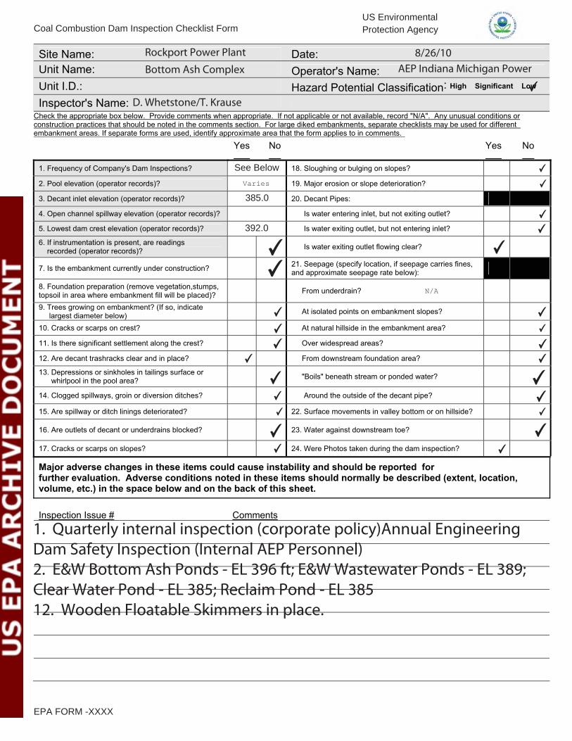
Site Name: Date: Unit Name: Operator's Name: Unit I.D.: Hazard Potential Classification: High Significant Low Inspector's Name:
Check the appropriate box below. Provide comments when appropriate. If not applicable or not available, record "N/A". Any unusual conditions or construction practices that should be noted in the comments section. For large diked embankments, separate checklists may be used for different embankment areas. If separate forms are used, identify approximate area that the form applies to in comments.
Yes No Yes No
1. Frequency of Company's Dam Inspections? 18. Sloughing or bulging on slopes? 2. Pool elevation (operator records)? 19. Major erosion or slope deterioration? 3. Decant inlet elevation (operator records)? 20. Decant Pipes: 4. Open channel spillway elevation (operator records)? Is water entering inlet, but not exiting outlet? 5. Lowest dam crest elevation (operator records)? Is water exiting outlet, but not entering inlet? 6. If instrumentation is present, are readings recorded (operator records)? Is water exiting outlet flowing clear?
7. Is the embankment currently under construction? 21. Seepage (specify location, if seepage carries fines, and approximate seepage rate below):
8. Foundation preparation (remove vegetation,stumps, topsoil in area where embankment fill will be placed)? From underdrain? 9. Trees growing on embankment? (If so, indicate largest diameter below) At isolated points on embankment slopes? 10. Cracks or scarps on crest? At natural hillside in the embankment area? 11. Is there significant settlement along the crest? Over widespread areas? 12. Are decant trashracks clear and in place? From downstream foundation area? 13. Depressions or sinkholes in tailings surface or whirlpool in the pool area? "Boils" beneath stream or ponded water? 14. Clogged spillways, groin or diversion ditches? Around the outside of the decant pipe? 15. Are spillway or ditch linings deteriorated? 22. Surface movements in valley bottom or on hillside? 16. Are outlets of decant or underdrains blocked? 23. Water against downstream toe? 17. Cracks or scarps on slopes? 24. Were Photos taken during the dam inspection? Major adverse changes in these items could cause instability and should be reported for further evaluation. Adverse conditions noted in these items should normally be described (extent, location, volume, etc.) in the space below and on the back of this sheet.
Inspection Issue # Comments
Coal Combustion Dam Inspection Checklist FormUS EnvironmentalProtection Agency
EPA FORM -XXXX
Varies
N/A
Rockport Power Plant 8/26/10Bottom Ash Complex AEP Indiana Michigan Power
✔
D. Whetstone/T. Krause
See Below
385.0
392.0
1. Quarterly internal inspection (corporate policy)Annual EngineeringDam Safety Inspection (Internal AEP Personnel)2. E&W Bottom Ash Ponds - EL 396 ft; E&WWastewater Ponds - EL 389;Clear Water Pond - EL 385; Reclaim Pond - EL 38512. Wooden Floatable Skimmers in place.
✔✔
✔
✔
✔
✔
✔✔
✔
✔✔
✔
✔
✔
✔
✔
✔
✔
✔
✔
✔✔✔
✔✔

U. S. Environmental Protection Agency
Coal Combustion Waste (CCW)
Impoundment Inspection
Impoundment NPDES Permit # IN0051845 INSPECTOR D. Whetstone/T. Kraus
Date 8/26/2010
Impoundment Name Bottom Ash Complex
Impoundment Company AEP Indiana Michigan Power
EPA Region 5
State Agency (Field Office) Address IN Dept. of Env. Mgt. (IDEM), Petersburg, IN
Name of Impoundment
(Report each impoundment on a separate form under the same Impoundment NPDES
Permit number)
New ________ Update _________
Yes No
Is impoundment currently under construction? X
Is water or ccw currently being pumped X
into the impoundment? Bottom Ash Only
IMPOUNDMENT FUNCTION: Detention of wastewaters and storage of CCW Solids
Nearest Downstream Town : Name Rockport, Indiana
Distance from the impoundment 1.5 miles
Impoundment
Location: Longitude 87 Degrees 2 Minutes 10.83 Seconds
Latitude 37 Degrees 55 Minutes 2.57 Seconds
State IN County Spencer
Does a state agency regulate this impoundment? YES ______ NO X
If So Which State Agency?___________________________________________
EPA Form XXXX-XXX, Jan 09

HAZARD POTENTIAL (In the event the impoundment should fail, the following would
occur):
______ LESS THAN LOW HAZARD POTENTIAL: Failure or misoperation of the
dam results in no probable loss of human life or economic or environmental losses.
X LOW HAZARD POTENTIAL: Dams assigned the low hazard potential
classification are those where failure or misoperation results in no probable loss of human
life and low economic and/or environmental losses. Losses are principally limited to the
owner’s property.
______ SIGNIFICANT HAZARD POTENTIAL: Dams assigned the significant hazard
potential classification are those dams where failure or misoperation results in no probable
loss of human life but can cause economic loss, environmental damage, disruption of
lifeline facilities, or can impact other concerns. Significant hazard potential classification
dams are often located in predominantly rural or agricultural areas but could be located in
areas with population and significant infrastructure.
______ HIGH HAZARD POTENTIAL: Dams assigned the high hazard potential
classification are those where failure or misoperation will probably cause loss of human
life.
DESCRIBE REASONING FOR HAZARD RATING CHOSEN:
The Bottom Ash Complex is diked on only one side of the impoundment. The dike is low
at only about 13 feet maximum height. An open grass area is present beyond the toe of
the dike which provides a wide buffer zone between the dike and closest roadway.
EPA Form XXXX-XXX, Jan 09

CONFIGURATION:
_____ Cross-Valley
_____ Side-Hill
_____ Diked
_____ Incised (form completion optional) X Combination Incised/Diked
Embankment Height 13 feet Embankment Material Native Silt/Clay Homogenous
Pool Area 136.7 acres Liner No (Native Soil)
Current Freeboard 3-5 during max operating condition ft Liner Permeability --
EPA Form XXXX-XXX, Jan 09

TYPE OF OUTLET (Mark all that apply)
_____ Open Channel Spillway
_____ Trapezoidal
_____ Triangular
_____ Rectangular
_____ Irregular
_____ depth
_____ bottom (or average) width
_____ top width
X Outlet
66 inside diameter
Material
X corrugated metal
_____ welded steel
_____ concrete
_____ plastic (hdpe, pvc, etc.)
_____ other (specify)
____________________
Is water flowing through the outlet? YES X NO _______
_____ No Outlet
X Other Type of Outlet (specify) Drop Inlet to 66” diameter CMP outlet pipe
The Impoundment was Designed By AEP with review by Casagrande & Associates
__________________________________________________________________
EPA Form XXXX-XXX, Jan 09

Has there ever been a failure at this site? YES __________ NO X
If So When? ___________________________
If So Please Describe : ___________________________________________________
______________________________________________________________________
______________________________________________________________________
______________________________________________________________________
______________________________________________________________________
______________________________________________________________________
______________________________________________________________________
______________________________________________________________________
______________________________________________________________________
______________________________________________________________________
______________________________________________________________________
______________________________________________________________________
______________________________________________________________________
______________________________________________________________________
______________________________________________________________________
______________________________________________________________________
______________________________________________________________________
______________________________________________________________________
______________________________________________________________________
______________________________________________________________________
______________________________________________________________________
______________________________________________________________________
______________________________________________________________________
______________________________________________________________________
______________________________________________________________________
______________________________________________________________________
______________________________________________________________________
______________________________________________________________________
______________________________________________________________________
______________________________________________________________________
EPA Form XXXX-XXX, Jan 09

Has there ever been significant seepages at this site? YES _______ NO X
If So When? ___________________________
IF So Please Describe: ___________________________________________________
______________________________________________________________________
______________________________________________________________________
______________________________________________________________________
______________________________________________________________________
______________________________________________________________________
______________________________________________________________________
______________________________________________________________________
______________________________________________________________________
______________________________________________________________________
______________________________________________________________________
______________________________________________________________________
______________________________________________________________________
______________________________________________________________________
______________________________________________________________________
______________________________________________________________________
______________________________________________________________________
______________________________________________________________________
______________________________________________________________________
______________________________________________________________________
______________________________________________________________________
______________________________________________________________________
______________________________________________________________________
______________________________________________________________________
______________________________________________________________________
______________________________________________________________________
______________________________________________________________________
______________________________________________________________________
______________________________________________________________________
______________________________________________________________________
______________________________________________________________________
EPA Form XXXX-XXX, Jan 09

Has there ever been any measures undertaken to monitor/lower Phreatic water able levels
based on past seepages or breaches at this site? YES ________NO X
If so, which method (e.g., piezometers, gw pumping,...)? ________________________
If so Please Describe : ____________________________________________
______________________________________________________________________
______________________________________________________________________
______________________________________________________________________
______________________________________________________________________
______________________________________________________________________
______________________________________________________________________
______________________________________________________________________
______________________________________________________________________
______________________________________________________________________
______________________________________________________________________
______________________________________________________________________
______________________________________________________________________
______________________________________________________________________
______________________________________________________________________
______________________________________________________________________
______________________________________________________________________
______________________________________________________________________
______________________________________________________________________
______________________________________________________________________
______________________________________________________________________
______________________________________________________________________
______________________________________________________________________
______________________________________________________________________
______________________________________________________________________
______________________________________________________________________
______________________________________________________________________
______________________________________________________________________
______________________________________________________________________
______________________________________________________________________
______________________________________________________________________
EPA Form XXXX-XXX, Jan 09

APPENDIX B
Photographs-Lower Ash Pond

Rockport Photolog - Appendix B1.docx
PHOTOGRAPHIC LOG (Appendix B) Client: US EPA Project Number: 46122
Site Name: Rockport Power Plant – Bottom Ash Complex Location: Rockport, IN
Orientation:
West
Description:
CCW sluice discharge into diversion structure that directs flow into the east or west bottom ash pond
Date:
8/26/2010
Photo Number:
1
Photographer:
TK
Orientation:
North
Description: Stockpiled bottom ash at north end of Bottom Ash Complex
Date: 8/26/2010
Photo Number: 2
Photographer: TK

Rockport Photolog - Appendix B1.docx
PHOTOGRAPHIC LOG (Appendix B) Client: US EPA Project Number: 46122
Site Name: Rockport Power Plant – Bottom Ash Complex Location: Rockport, IN
Orientation:
South
Description:
Crest of West Bottom Ash Pond Dike
Date:
8/26/10
Photo Number:
3
Photographer:
DDW
Orientation:
North
Description: Outboard slope of west dike.
Date: 8/26/2010
Photo Number: 4
Photographer: TK

Rockport Photolog - Appendix B1.docx
PHOTOGRAPHIC LOG (Appendix B) Client: US EPA Project Number: 46122
Site Name: Rockport Power Plant – Bottom Ash Complex Location: Rockport, IN
Orientation:
NW
Description: Dishcharge Structure No. 3 at south end of west bottom ash pond
Date:
8/26/2010
Photo Number:
5
Photographer:
TK
Orientation:
West
Description: Divider dike and decanting weir at south end of west waste water pond
Date: 8/26/2010
Photo Number: 6
Photographer: TK
Rockport Photolog - Appendix B1.docx
PHOTOGRAPHIC LOG (Appendix B) Client: US EPA Project Number: 46122
Site Name: Rockport Power Plant – Bottom Ash Complex Location: Rockport, IN
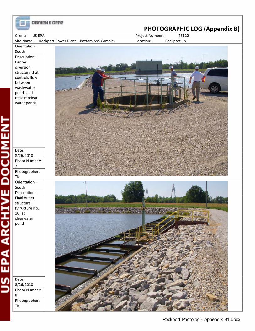
Orientation:
South
Description:
Center diversion structure that controls flow between wastewater ponds and reclaim/clear water ponds
Date:
8/26/2010
Photo Number:
7
Photographer:
TK
Orientation:
South
Description:
Final outlet structure (Structure No. 10) at clearwater pond
Date:
8/26/2010
Photo Number:
8
Photographer:
TK