Dallas RMD 169 Texas DJ - blaupunkt.com · C1 C2 C3 1Line Out LR 7 - 13 Bus - In 2 Line Out RR 8...
6
Radio / MD Dallas RMD 169 Texas DJ Instrucciones de instalación Instruções de montagem Installation instructions Notice de montage
Transcript of Dallas RMD 169 Texas DJ - blaupunkt.com · C1 C2 C3 1Line Out LR 7 - 13 Bus - In 2 Line Out RR 8...

Radio / MD
Dallas RMD 169Texas DJ
Instrucciones de instalaciónInstruções de montagem
Installation instructionsNotice de montage
Tönnies
Tönnies
Tönnies
Tönnies
Tönnies

135
EN
GL
ISH
FR
AN
ÇA
ISE
SP
AÑ
OL
PO
RTU
GU
ÊS
GB Safety precautionsInstallation and connection regulations– In the event that this equipment is installed
or repaired incorrectly, this could causemalfunctions in the vehicle electronics.
– To avoid causing damage to your radio,use the corresponding Blaupunkt adaptercable to connect the 8-pin +/- ISO plug inthe vehicle.
While installing and connecting this equip-ment, please observe the following safetynotes.– Disconnect the negative battery terminal.– Observe the car manufacturer’s safety in-
structions.– If you drill any holes, make sure that you
do not damage any parts of the vehicle.– The diameter of the positive/negative ca-
ble must not be less than 16 GA.
F Indications de sécuritéConsignes de montage et de branchement– En cas d’erreur d’installation ou d’entre-
tien, des perturbations peuvent survenir auniveau des systèmes électroniques duvéhicule.
– Pour ne pas détériorer votre autoradio,branchez le connecteur ISO +/- 8 pôlesdu véhicule uniquement via un câble adap-tateur Blaupunkt correspondant.
Pendant le montage et le branchement,observez les consignes de sécurité suivan-tes :– Débrancher le pôle (-) de la batterie.
– Observer ce faisant les indications de sé-curité du constructeur automobile.
– Veiller à ne pas endommager les piècesdu véhicule en perçant des trous.
– La section transversale du câble (+) et (-)ne doit pas être inférieure à 1,5 mm2.
E Normas de seguridadEspecificaciones sobre la instalación yconexión– En caso de realizarse una instalación o un
mantenimiento inadecuado, éstos puedenocasionar fallos en las funciones de lossistemas eléctricos del vehículo.
– Para que su radio no sufra daños, debeconectar el enchufe del vehículo de 8 po-los +/- ISO sólo al correspondiente cableadaptador Blaupunkt.
Durante el montaje y la conexión observelas siguientes normas de seguridad.– Desemborne el polo negativo de la bate-
ría.– Al hacerlo, observe las normas de seguri-
dad del fabricante del vehículo.– Al taladrar orificios asegúrese de que el
vehículo no sufra ningún daño.– El diámetro del cable positivo y negativo
no debe ser menor a 1,5 mm2.
P Indicações de segurançaDirectivas de montagem e de conexão– Podem ocorrer erros de funcionamento em
sistemas electrónicos de automóveis de-
Installation and connection instructions • Notice de montage et de branchement • Instrucciones para la instalación y conexión •Instrução de montagem e de conexão
vido à uma instalação ou manutenção er-rada.
– Para evitar a destruição do seu rádio, de-verá apenas ligar a ficha ISO de 8 pólosdo automóvel através de um respectivocabo de adaptação Blaupunkt.
Observe por favor as seguintes indicaçõesde segurança durante a montagem e a li-gação– Separar por pressão o pólo negativo da
bateria.– Observar as indicações de segurança do
fabricante do automóvel.– Ao furar orifícios, deverá observar que não
sejam danificadas partes do automóvel.– O diâmetro do cabo positivo e negativo não
deve ser inferior a 1,5 mm2.

136
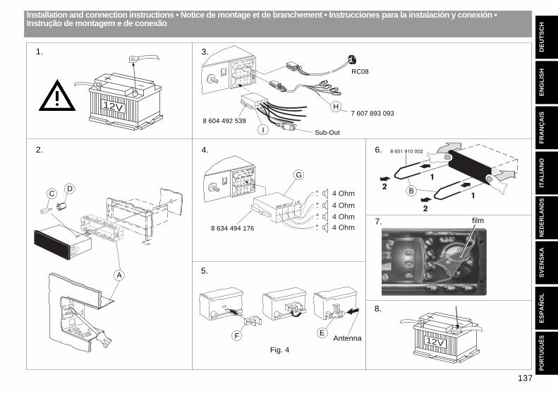
Supplied Mounting Hardware - Materiel de montage fourni - Componenti di fissaggio comprese nella fornitura - Elementosde fixação fornecidos.
Installation and connection instructions • Notice de montage et de branchement • Instrucciones para la instalación y conexión •Instrução de montagem e de conexão
D
AC
E
KH
G
B
I
F
137
EN
GL
ISH
DE
UT
SC
HF
RA
NÇ
AIS
ITA
LIA
NO
NE
DE
RLA
ND
SS
VE
NS
KA
ES
PA
ÑO
LP
OR
TUG
UÊ
SAntenna
Fig. 4
1.
2.
3.
4.
5.
6.
8.
A
CD
F E
8 601 910 002
2
2
1
1
7. 8 634 494 176
film
12V
12V
53
182165
1-20
Installation and connection instructions • Notice de montage et de branchement • Instrucciones para la instalación y conexión •Instrução de montagem e de conexão
RR RF LF LR
10A
4 Ohm
4 Ohm4 Ohm
4 Ohm
+-+-+-+-
G
B
Sub-Out
8 604 492 5397 607 893 093
10A
H
RC08
I
138
1
2
3
4
5
6
7
8
1
2
3
4
5
6
7
8
C
B
A
1 4 7 10 13 16 19
3 6 9 12 15 18
2 5 8 11 14 17 20
C-1 C-2 C-3
RC 08
Fig.10
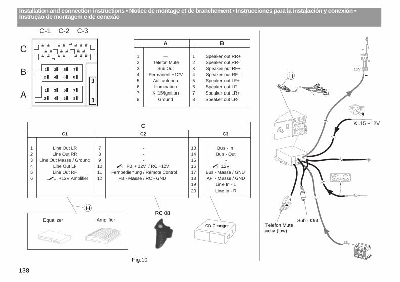
A B
1 — 1 Speaker out RR+2 Telefon Mute 2 Speaker out RR-3 Sub Out 3 Speaker out RF+4 Permanent +12V 4 Speaker out RF-5 Aut. antenna 5 Speaker out LF+6 Illumination 6 Speaker out LF-7 Kl.15/Ignition 7 Speaker out LR+8 Ground 8 Speaker out LR-
CC1 C2 C3
1 Line Out LR 7 - 13 Bus - In2 Line Out RR 8 - 14 Bus - Out3 Line Out Masse / Ground 9 - 15 -4 Line Out LF 10 FB + 12V / RC +12V 16 12V5 Line Out RF 11 Fernbedienung / Remote Control 17 Bus - Masse / GND6 +12V Amplifier 12 FB - Masse / RC - GND 18 AF - Masse / GND
19 Line In - L20 Line In - R
CD-Changer
Installation and connection instructions • Notice de montage et de branchement • Instrucciones para la instalación y conexión •Instrução de montagem e de conexão
AmplifierEqualizer
H
Sub - OutTelefon Muteactiv-(low)
Relais
10A
12V
Kl.15 +12V
12V
H

139
EN
GL
ISH
DE
UT
SC
HF
RA
NÇ
AIS
ITA
LIA
NO
NE
DE
RLA
ND
SS
VE
NS
KA
ES
PA
ÑO
LP
OR
TUG
UÊ
S