Daily Operations Guide -...
48
SAFETY WARNING Only qualified personnel should install and service the equipment. The installation, starting up, and servicing of heating, ventilating, and air-conditioning equipment can be hazardous and requires specific knowledge and training. Improperly installed, adjusted or altered equipment by an unqualified person could result in death or serious injury. When working on the equipment, observe all precautions in the literature and on the tags, stickers, and labels that are attached to the equipment. October 2016 BAS-SVU025D-EN Tracer ® SC System Controller Daily Operations Guide
Transcript of Daily Operations Guide -...

SSAAFFEETTYYWWAARRNNIINNGGOnly qualified personnel should install and service the equipment. The installation, starting up, and servicing of heating, ventilating, and
air-conditioning equipment can be hazardous and requires specific knowledge and training. Improperly installed, adjusted or altered
equipment by an unqualified person could result in death or serious injury. When working on the equipment, observe all precautions in the
literature and on the tags, stickers, and labels that are attached to the equipment.
October 2016 BAS-SVU025D-EN
Tracer®® SC System Controller
Daily Operations Guide

©2016 Ingersoll Rand All rights reserved BAS-SVU025D-EN
IntroductionRead this manual thoroughly before operating or servicing this unit.
Warnings, Cautions, and NoticesSafety advisories appear throughout this manual as required. Your personal safety and the
proper operation of this machine depend upon the strict observance of these precautions.
The three types of advisories are defined as follows:
Indicates a potentially hazardous situation which, if not avoided, could result indeath or serious injury.
Indicates a potentially hazardous situation which, if not avoided, could result inminor or moderate injury. It could also be used to alert against unsafe practices.
Indicates a situation that could result in equipment or property-damage onlyaccidents.
Important Environmental ConcernsScientific research has shown that certain man-made chemicals can affect the earth’s naturally
occurring stratospheric ozone layer when released to the atmosphere. In particular, several of the
identified chemicals that may affect the ozone layer are refrigerants that contain Chlorine,
Fluorine and Carbon (CFCs) and those containing Hydrogen, Chlorine, Fluorine and Carbon
(HCFCs). Not all refrigerants containing these compounds have the same potential impact to the
environment. Trane advocates the responsible handling of all refrigerants-including industry
replacements for CFCs and HCFCs such as saturated or unsaturated HFCs and HCFCs.
Important Responsible Refrigerant PracticesTrane believes that responsible refrigerant practices are important to the environment, our
customers, and the air conditioning industry. All technicians who handle refrigerants must be
certified. The Federal Clean Air Act (Section 608) sets forth the requirements for handling,
reclaiming, recovering and recycling of certain refrigerants and the equipment that is used in
these service procedures. In addition, some states or municipalities may have additional
requirements that must also be adhered to for responsible management of refrigerants. Know
the applicable laws and follow them.
WWAARRNNIINNGGPPrrooppeerr FFiieelldd WWiirriinngg aanndd GGrroouunnddiinngg RReeqquuiirreedd!!FFaaiilluurree ttoo ffoollllooww ccooddee ccoouulldd rreessuulltt iinn ddeeaatthh oorr sseerriioouuss iinnjjuurryy..
AAllll ffiieelldd wwiirriinngg MMUUSSTT bbee ppeerrffoorrmmeedd bbyy qquuaalliiffiieedd ppeerrssoonnnneell.. IImmpprrooppeerrllyy iinnssttaalllleedd aanndd
ggrroouunnddeedd ffiieelldd wwiirriinngg ppoosseess FFIIRREE aanndd EELLEECCTTRROOCCUUTTIIOONN hhaazzaarrddss.. TToo aavvooiidd tthheessee hhaazzaarrddss,,
yyoouu MMUUSSTT ffoollllooww rreeqquuiirreemmeennttss ffoorr ffiieelldd wwiirriinngg iinnssttaallllaattiioonn aanndd ggrroouunnddiinngg aass ddeessccrriibbeedd iinn
NNEECC aanndd yyoouurr llooccaall//ssttaattee eelleeccttrriiccaall ccooddeess..

BAS-SVU025D-EN 3
WWAARRNNIINNGGPPeerrssoonnaall PPrrootteeccttiivvee EEqquuiippmmeenntt ((PPPPEE)) RReeqquuiirreedd!!FFaaiilluurree ttoo wweeaarr pprrooppeerr PPPPEE ffoorr tthhee jjoobb bbeeiinngg uunnddeerrttaakkeenn ccoouulldd rreessuulltt iinn ddeeaatthh oorr sseerriioouuss
iinnjjuurryy..
TTeecchhnniicciiaannss,, iinn oorrddeerr ttoo pprrootteecctt tthheemmsseellvveess ffrroomm ppootteennttiiaall eelleeccttrriiccaall,, mmeecchhaanniiccaall,, aanndd
cchheemmiiccaall hhaazzaarrddss,, MMUUSSTT ffoollllooww pprreeccaauuttiioonnss iinn tthhiiss mmaannuuaall aanndd oonn tthhee ttaaggss,, ssttiicckkeerrss,, aanndd
llaabbeellss,, aass wweellll aass tthhee iinnssttrruuccttiioonnss bbeellooww::
•• BBeeffoorree iinnssttaalllliinngg//sseerrvviicciinngg tthhiiss uunniitt,, tteecchhnniicciiaannss MMUUSSTT ppuutt oonn aallll PPPPEE rreeqquuiirreedd ffoorr
tthhee wwoorrkk bbeeiinngg uunnddeerrttaakkeenn ((EExxaammpplleess;; ccuutt rreessiissttaanntt gglloovveess//sslleeeevveess,, bbuuttyyll gglloovveess,,
ssaaffeettyy ggllaasssseess,, hhaarrdd hhaatt//bbuummpp ccaapp,, ffaallll pprrootteeccttiioonn,, eelleeccttrriiccaall PPPPEE aanndd aarrcc ffllaasshh
ccllootthhiinngg)).. AALLWWAAYYSS rreeffeerr ttoo aapppprroopprriiaattee MMaatteerriiaall SSaaffeettyy DDaattaa SShheeeettss ((MMSSDDSS))//SSaaffeettyy
DDaattaa SShheeeettss ((SSDDSS)) aanndd OOSSHHAA gguuiiddeelliinneess ffoorr pprrooppeerr PPPPEE..
•• WWhheenn wwoorrkkiinngg wwiitthh oorr aarroouunndd hhaazzaarrddoouuss cchheemmiiccaallss,, AALLWWAAYYSS rreeffeerr ttoo tthhee
aapppprroopprriiaattee MMSSDDSS//SSDDSS aanndd OOSSHHAA//GGHHSS ((GGlloobbaall HHaarrmmoonniizzeedd SSyysstteemm ooff
CCllaassssiiffiiccaattiioonn aanndd LLaabbeelllliinngg ooff CChheemmiiccaallss)) gguuiiddeelliinneess ffoorr iinnffoorrmmaattiioonn oonn aalllloowwaabbllee
ppeerrssoonnaall eexxppoossuurree lleevveellss,, pprrooppeerr rreessppiirraattoorryy pprrootteeccttiioonn aanndd hhaannddlliinngg iinnssttrruuccttiioonnss..
•• IIff tthheerree iiss aa rriisskk ooff eenneerrggiizzeedd eelleeccttrriiccaall ccoonnttaacctt,, aarrcc,, oorr ffllaasshh,, tteecchhnniicciiaannss MMUUSSTT ppuutt
oonn aallll PPPPEE iinn aaccccoorrddaannccee wwiitthh OOSSHHAA,, NNFFPPAA 7700EE,, oorr ootthheerr ccoouunnttrryy--ssppeecciiffiicc
rreeqquuiirreemmeennttss ffoorr aarrcc ffllaasshh pprrootteeccttiioonn,, PPRRIIOORR ttoo sseerrvviicciinngg tthhee uunniitt.. NNEEVVEERR PPEERRFFOORRMM
AANNYY SSWWIITTCCHHIINNGG,, DDIISSCCOONNNNEECCTTIINNGG,, OORR VVOOLLTTAAGGEE TTEESSTTIINNGG WWIITTHHOOUUTT PPRROOPPEERR
EELLEECCTTRRIICCAALL PPPPEE AANNDD AARRCC FFLLAASSHH CCLLOOTTHHIINNGG.. EENNSSUURREE EELLEECCTTRRIICCAALL MMEETTEERRSS AANNDD
EEQQUUIIPPMMEENNTTAARREE PPRROOPPEERRLLYY RRAATTEEDD FFOORR IINNTTEENNDDEEDD VVOOLLTTAAGGEE..
CopyrightThis document and the information in it are the property of Trane, and may not be used or
reproduced in whole or in part without written permission. Trane reserves the right to revise this
publication at any time, and to make changes to its content without obligation to notify any
person of such revision or change.
TrademarksAll trademarks referenced in this document are the trademarks of their respective owners.
Revision HistoryBBAASS--SSVVUU002255DD--EENN:
• Document title name changed back to the original: “Daily Operations Guide.”
BBAASS--SSVVUU002255CC--EENN:
• Updated Tracer SC components description with new Modbus communication.
BBAASS--SSVVUU002255BB--EENN::
• Updated screen shots to reflect current user interface
• Added additional items in the Tools section
IInnttrroodduuccttiioonn
4 BAS-SVU025D-EN
How to Use This Guide . . . . . . . . . . . . . . . . . . . . . . . . . . . . . . . . . . . . . . . . . . . . . . . . . . . . . . . . 7
Resources. . . . . . . . . . . . . . . . . . . . . . . . . . . . . . . . . . . . . . . . . . . . . . . . . . . . . . . . . . . . . . . . . . . 7
Product Overview. . . . . . . . . . . . . . . . . . . . . . . . . . . . . . . . . . . . . . . . . . . . . . . . . . . . . . . . . . . . . . 8
Tracer® SC Model Numbers . . . . . . . . . . . . . . . . . . . . . . . . . . . . . . . . . . . . . . . . . . . . . . . . . . 8
Tracer® SC Components . . . . . . . . . . . . . . . . . . . . . . . . . . . . . . . . . . . . . . . . . . . . . . . . . . . . . 8
Tracer® SC Accessories . . . . . . . . . . . . . . . . . . . . . . . . . . . . . . . . . . . . . . . . . . . . . . . . . . . . . . 9
Tracer® SC Service Parts . . . . . . . . . . . . . . . . . . . . . . . . . . . . . . . . . . . . . . . . . . . . . . . . . . . . . 9
Licensing and Hardware . . . . . . . . . . . . . . . . . . . . . . . . . . . . . . . . . . . . . . . . . . . . . . . . . . . . . .11
Setup Requirements . . . . . . . . . . . . . . . . . . . . . . . . . . . . . . . . . . . . . . . . . . . . . . . . . . . . . . . . .11
The User Interface . . . . . . . . . . . . . . . . . . . . . . . . . . . . . . . . . . . . . . . . . . . . . . . . . . . . . . . . . . . . 13
Applying Table Filters . . . . . . . . . . . . . . . . . . . . . . . . . . . . . . . . . . . . . . . . . . . . . . . . . . . . . . . 14
Using the Actions Button . . . . . . . . . . . . . . . . . . . . . . . . . . . . . . . . . . . . . . . . . . . . . . . . . . . . 14
The Navigation Tree . . . . . . . . . . . . . . . . . . . . . . . . . . . . . . . . . . . . . . . . . . . . . . . . . . . . . . . . . . 16
Using the Navigation Tree . . . . . . . . . . . . . . . . . . . . . . . . . . . . . . . . . . . . . . . . . . . . . . . . . . . 16
Drag a Tracer® SC Component onto the Tree . . . . . . . . . . . . . . . . . . . . . . . . . . . . . . 17
Drag a Tree Component onto the Home Button . . . . . . . . . . . . . . . . . . . . . . . . . . . . 17
Drag a Tree Component onto the Home Button . . . . . . . . . . . . . . . . . . . . . . . . . . . . 18
Drag Tree Nodes to Other Locations . . . . . . . . . . . . . . . . . . . . . . . . . . . . . . . . . . . . . . 18
Rename Tree Nodes . . . . . . . . . . . . . . . . . . . . . . . . . . . . . . . . . . . . . . . . . . . . . . . . . . . . . 18
Add a Custom Graphics Node to the Tree. . . . . . . . . . . . . . . . . . . . . . . . . . . . . . . . . . 18
Edit a Node on the Tree . . . . . . . . . . . . . . . . . . . . . . . . . . . . . . . . . . . . . . . . . . . . . . . . . . 18
Add a Custom Folder to the Tree. . . . . . . . . . . . . . . . . . . . . . . . . . . . . . . . . . . . . . . . . . 18
Delete a Node from the Tree. . . . . . . . . . . . . . . . . . . . . . . . . . . . . . . . . . . . . . . . . . . . . . 19
Undo a Change to the Tree . . . . . . . . . . . . . . . . . . . . . . . . . . . . . . . . . . . . . . . . . . . . . . . 19
Redo a Previously Undone Change to the Tree . . . . . . . . . . . . . . . . . . . . . . . . . . . . . 19
Reset the Tree to Standard Configuration. . . . . . . . . . . . . . . . . . . . . . . . . . . . . . . . . . 19
Alarms. . . . . . . . . . . . . . . . . . . . . . . . . . . . . . . . . . . . . . . . . . . . . . . . . . . . . . . . . . . . . . . . . . . . . . . . 20
Taking Action on an Alarm. . . . . . . . . . . . . . . . . . . . . . . . . . . . . . . . . . . . . . . . . . . . . . . . . . . 20
Alarm Categories . . . . . . . . . . . . . . . . . . . . . . . . . . . . . . . . . . . . . . . . . . . . . . . . . . . . . . . . . . . 20
Reports . . . . . . . . . . . . . . . . . . . . . . . . . . . . . . . . . . . . . . . . . . . . . . . . . . . . . . . . . . . . . . . . . . . . . . . 21
Creating a New Report . . . . . . . . . . . . . . . . . . . . . . . . . . . . . . . . . . . . . . . . . . . . . . . . . . . . . . 21
Exporting a Report . . . . . . . . . . . . . . . . . . . . . . . . . . . . . . . . . . . . . . . . . . . . . . . . . . . . . . . . . . 22
Data Logs. . . . . . . . . . . . . . . . . . . . . . . . . . . . . . . . . . . . . . . . . . . . . . . . . . . . . . . . . . . . . . . . . . . . . 23
Scheduled Data Logs. . . . . . . . . . . . . . . . . . . . . . . . . . . . . . . . . . . . . . . . . . . . . . . . . . . . . . . . 23
Creating a Scheduled Data Log . . . . . . . . . . . . . . . . . . . . . . . . . . . . . . . . . . . . . . . . . . . 23
Triggered Data Logs. . . . . . . . . . . . . . . . . . . . . . . . . . . . . . . . . . . . . . . . . . . . . . . . . . . . . . . . . 24
Creating a Triggered Data Log . . . . . . . . . . . . . . . . . . . . . . . . . . . . . . . . . . . . . . . . . . . . 24
Spaces. . . . . . . . . . . . . . . . . . . . . . . . . . . . . . . . . . . . . . . . . . . . . . . . . . . . . . . . . . . . . . . . . . . . . . . . 26
Table of Contents

BAS-SVU025D-EN 5
Equipment. . . . . . . . . . . . . . . . . . . . . . . . . . . . . . . . . . . . . . . . . . . . . . . . . . . . . . . . . . . . . . . . . . . . 28
Schedules . . . . . . . . . . . . . . . . . . . . . . . . . . . . . . . . . . . . . . . . . . . . . . . . . . . . . . . . . . . . . . . . . . . . 30
Optimal Start/Stop . . . . . . . . . . . . . . . . . . . . . . . . . . . . . . . . . . . . . . . . . . . . . . . . . . . . . . . . . . 30
Exceptions and Calendars . . . . . . . . . . . . . . . . . . . . . . . . . . . . . . . . . . . . . . . . . . . . . . . . . . . 30
Creating a Schedule . . . . . . . . . . . . . . . . . . . . . . . . . . . . . . . . . . . . . . . . . . . . . . . . . . . . . . . . . 31
Points. . . . . . . . . . . . . . . . . . . . . . . . . . . . . . . . . . . . . . . . . . . . . . . . . . . . . . . . . . . . . . . . . . . . . . . . . 32
Points Types. . . . . . . . . . . . . . . . . . . . . . . . . . . . . . . . . . . . . . . . . . . . . . . . . . . . . . . . . . . . . . . . 32
Point Overrides . . . . . . . . . . . . . . . . . . . . . . . . . . . . . . . . . . . . . . . . . . . . . . . . . . . . . . . . . . . . . . . 33
Performing Simple Overrides . . . . . . . . . . . . . . . . . . . . . . . . . . . . . . . . . . . . . . . . . . . . . . . . 33
Systems . . . . . . . . . . . . . . . . . . . . . . . . . . . . . . . . . . . . . . . . . . . . . . . . . . . . . . . . . . . . . . . . . . . . . . 35
Area Application . . . . . . . . . . . . . . . . . . . . . . . . . . . . . . . . . . . . . . . . . . . . . . . . . . . . . . . . . . . . 35
Variable Air Systems (VAS) Application . . . . . . . . . . . . . . . . . . . . . . . . . . . . . . . . . . . . . . . 35
Chiller Plant Control (CPC) Application. . . . . . . . . . . . . . . . . . . . . . . . . . . . . . . . . . . . . . . . 35
Viewing System Status . . . . . . . . . . . . . . . . . . . . . . . . . . . . . . . . . . . . . . . . . . . . . . . . . . . . . . 36
The Tools Menu. . . . . . . . . . . . . . . . . . . . . . . . . . . . . . . . . . . . . . . . . . . . . . . . . . . . . . . . . . . . . . . 37
Backup and Restore . . . . . . . . . . . . . . . . . . . . . . . . . . . . . . . . . . . . . . . . . . . . . . . . . . . . . . . . . 37
Custom Graphics . . . . . . . . . . . . . . . . . . . . . . . . . . . . . . . . . . . . . . . . . . . . . . . . . . . . . . . . . . . 38
Global Referencers. . . . . . . . . . . . . . . . . . . . . . . . . . . . . . . . . . . . . . . . . . . . . . . . . . . . . . . . . . 38
Programs . . . . . . . . . . . . . . . . . . . . . . . . . . . . . . . . . . . . . . . . . . . . . . . . . . . . . . . . . . . . . . . . . . 39
System Logs . . . . . . . . . . . . . . . . . . . . . . . . . . . . . . . . . . . . . . . . . . . . . . . . . . . . . . . . . . . . . . . 39
Tracer Ensemble IPAddress . . . . . . . . . . . . . . . . . . . . . . . . . . . . . . . . . . . . . . . . . . . . . . . . . 39
Resource Usage . . . . . . . . . . . . . . . . . . . . . . . . . . . . . . . . . . . . . . . . . . . . . . . . . . . . . . . . . . . . 39
BACnet Information . . . . . . . . . . . . . . . . . . . . . . . . . . . . . . . . . . . . . . . . . . . . . . . . . . . . . . . . . 39
Unit Controllers. . . . . . . . . . . . . . . . . . . . . . . . . . . . . . . . . . . . . . . . . . . . . . . . . . . . . . . . . . . . . . . 40
Trane Unit Controllers Supported by Tracer SC . . . . . . . . . . . . . . . . . . . . . . . . . . . . . . . . 40
Unit Controllers (Comm3/4) Supported by Tracer SC Through the Legacy
Communications Bridge. . . . . . . . . . . . . . . . . . . . . . . . . . . . . . . . . . . . . . . . . . . . . . . . . . . . . 40
Trane Legacy Comm Chillers Support by Tracer SC . . . . . . . . . . . . . . . . . . . . . . . . . . . . 41
Non-Trane Unit controllers Support by Tracer SC . . . . . . . . . . . . . . . . . . . . . . . . . . . . . . 41
Quantity of Unit Controllers Supported by Tracer SC . . . . . . . . . . . . . . . . . . . . . . . . . . . 41
LEDs and the 7–Segment Display . . . . . . . . . . . . . . . . . . . . . . . . . . . . . . . . . . . . . . . . . . . . . 42
Powering Up/Powering Down the Tracer SC. . . . . . . . . . . . . . . . . . . . . . . . . . . . . . . . . . . 42
The LEDs and the 7–Segment Display . . . . . . . . . . . . . . . . . . . . . . . . . . . . . . . . . . . . . . . . 42
Interpreting the LEDs. . . . . . . . . . . . . . . . . . . . . . . . . . . . . . . . . . . . . . . . . . . . . . . . . . . . . . . . 43
TTaabbllee ooff CCoonntteennttss

6 BAS-SVU025D-EN
Interpreting the 7–Segment Display . . . . . . . . . . . . . . . . . . . . . . . . . . . . . . . . . . . . . . . . . . 43
Troubleshooting . . . . . . . . . . . . . . . . . . . . . . . . . . . . . . . . . . . . . . . . . . . . . . . . . . . . . . . . . . . . . . 45
Troubleshooting with LEDs and the 7-Segment Display . . . . . . . . . . . . . . . . . . . . . . . . 45
Force Return to Factory Defaults . . . . . . . . . . . . . . . . . . . . . . . . . . . . . . . . . . . . . . . . . . . . . 45
Troubleshooting Network Connections . . . . . . . . . . . . . . . . . . . . . . . . . . . . . . . . . . . . . . . 46
PING . . . . . . . . . . . . . . . . . . . . . . . . . . . . . . . . . . . . . . . . . . . . . . . . . . . . . . . . . . . . . . . . . . . 46
IPCONFIG . . . . . . . . . . . . . . . . . . . . . . . . . . . . . . . . . . . . . . . . . . . . . . . . . . . . . . . . . . . . . . 46
TTaabbllee ooff CCoonntteennttss

BAS-SVU025D-EN 7
How to Use This GuideAlthough it is best practice to familiarize yourself with all aspects of Tracer SC, it is not necessary
to read this guide in any particular order or in its entirety. To quickly locate a specific task or topic,
simply refer to the Table of Contents in this guide.
The sections in this guide that describe Tracer SC applications will begin with an overview of the
application (Alarms, Reports, for example) and an accompanying figure that shows the
application highlighted on the left-hand navigation bar.
This guide does not cover programming and configuration. For more information on advanced
user tasks, refer to the Tracer SC System Controller Installation and Setup Guide, BAS-SVX31,oraccess the Tracer SC Help by clicking the help icon located on the global navigation bar.
NNoottee:: If you are reading a copy of this document that was translated from English, please notethat all figures and illustrations in this guide are for navigational purposes only. The dataand text depicted is not relevant to the accompanying instructions.
ResourcesThe following is a list of related Tracer® SC documentation and training resources.
• TTrraacceerr SSCC SSyysstteemm CCoonnttrroolllleerr IInnssttaallllaattiioonn aanndd SSeettuupp GGuuiiddee ((BBAASS--SSVVXX3311))
Describes detailed configuration for network settings, Ethernet network wiring, and IT
security.
• TTrraacceerr SSCC SSyysstteemm CCoonnttrroolllleerr IInnssttaallllaattiioonn SShheeeett ((XX3399664411115544--0011))
For mounting the enclosure and providing AC power.
• TTrraacceerr SSCC oonnlliinnee hheellpp
An online help system is included with the Tracer SC user interface. Global help has a
table of contents and is searchable. Contextual help is specific to the information on each
page.
• TTrraacceerr BBAASS OOppeerraattoorr SSuuiittee ((MMoobbiillee AApppp)) GGeettttiinngg SSttaarrtteedd GGuuiiddee ((BBAASS--SSVVUU2233))
Describes how to obtain, download, install, and set up the mobile app.
• BBAACCnneett®® MMSS//TTPP WWiirriinngg BBeesstt PPrraaccttiicceess aanndd TTrroouubblleesshhoooottiinngg ((BBAASS--SSVVXX005511))
Provides best practices, procedures, and troubleshooting for wiring BACnet unit
controllers to a Tracer SC system controller.
• TTrraacceerr SSCC AAiirr SSyysstteemmss AApppplliiccaattiioonn GGuuiiddee ((BBAASS--AAPPGG000077))
Describes variable-air-volume strategies for variable air systems. It also include constant-
volume applications and area application strategies for Tracer SC.
• TTrraacceerr GGrraapphhiiccaall PPrrooggrraammmmiinngg ((TTGGPP22)) AApppplliiccaattiioonnss GGuuiiddee ((BBAASS--AAPPGG000088))
Describes how to use the TGP2 editor and typical implementation strategies and best
practices for using TGP2.
• TTrraacceerr TTUU SSeerrvviiccee TTooooll GGeettttiinngg SSttaarrtteedd GGuuiiddee ((TTTTUU--SSVVNN0011))
This document describes how to use the Tracer TU service tool to
– Transfer programs to the Tracer SC
– Start the Tracer Graphical Programming (TGP2) Editor and the Tracer Graphics Editor
from within Tracer TU
– Backing up and restoring firmware and TGP2 programs
• TTrraannee CCoolllleeggee ooff BBuuiillddiinngg AAuuttoommaattiioonn
The Trane College of Building Automation (TCBA) offers a comprehensive portfolio of
technical courses to help you effectively monitor and coordinate your HVAC equipment
and systems.
http://www.trane.com/Commercial/DNA/view.aspx?i=586
8 BAS-SVU025D-EN
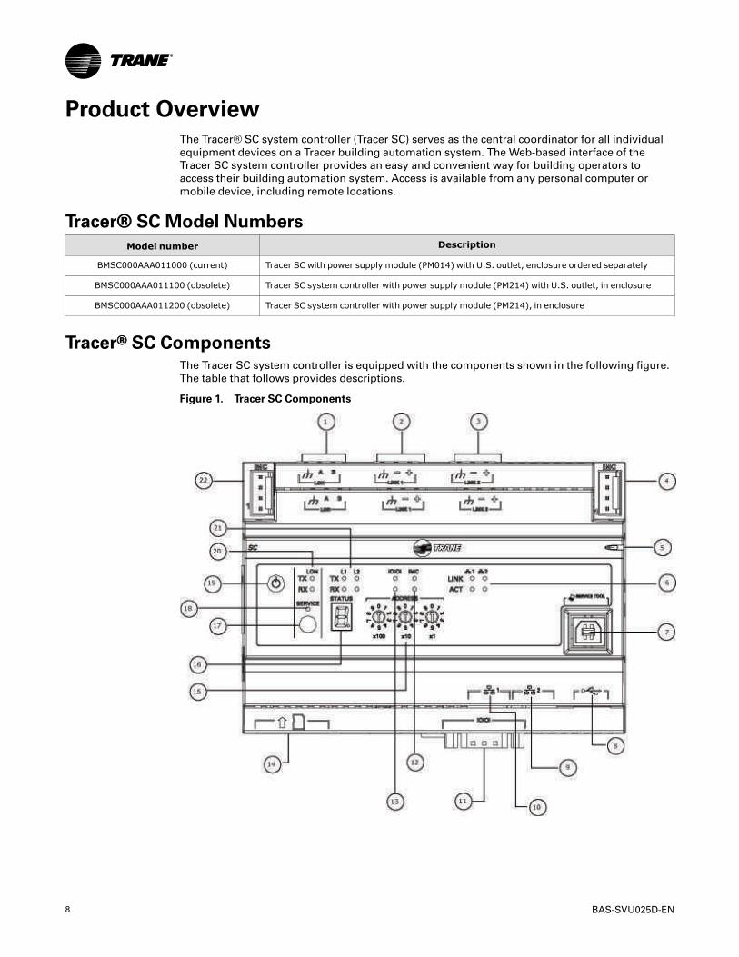
Product OverviewThe Tracer® SC system controller (Tracer SC) serves as the central coordinator for all individual
equipment devices on a Tracer building automation system. The Web-based interface of the
Tracer SC system controller provides an easy and convenient way for building operators to
access their building automation system. Access is available from any personal computer or
mobile device, including remote locations.
Tracer®® SC Model NumbersModel number Description
BMSC000AAA011000 (current) Tracer SC with power supply module (PM014) with U.S. outlet, enclosure ordered separately
BMSC000AAA011100 (obsolete) Tracer SC system controller with power supply module (PM214) with U.S. outlet, in enclosure
BMSC000AAA011200 (obsolete) Tracer SC system controller with power supply module (PM214), in enclosure
Tracer®® SC ComponentsThe Tracer SC system controller is equipped with the components shown in the following figure.
The table that follows provides descriptions.
Figure 1. Tracer SC Components

BAS-SVU025D-EN 9
Callout Number inFigure Tracer SC Components Description
1 LonTalk LINK
2 BACnet MS/TP or Modbus RTU LINK 1
3 BACnet MS/TP or Modbus RTU LINK 2
4, 22 IMC Connections
5 Status LED
6 Ethernet LEDs
7 USB service tool port
8 USB host (future)
9Ethernet network connection 2 (supports TCP/IP, recommended for direct connection toPC)
10Ethernet network connection 1 (supports Modbus TCP, BACnet and TCP/TP; recommendedfor building network connections)
11 EIA-232 serial connection
12 IMC LEDs
13 EIA-232 LEDs
14 SD card port (future)
15 Rotary switches
16 7-segment display
17 LonTalk service pin
18 LonTalk service LED
19 Power button
20 LonTalk LEDs
21 BACnet LEDs
Tracer®® SC AccessoriesDescription Order number
BACnet terminator 2 pack (a) X1365152401
Rover LonTalk interface adaptor(b) S3090062062
(a) For information about this accessory, see BACnet MS/TP Wiring Best Practices (BAS-SVX051)(b) For more information about this accessory, see Rover Service Tool Installation, Operation, and Programming (EMTX-
SVX01).
Tracer®® SC Service PartsService parts for the Tracer SC are shown in the following figure. The following tables provide
descriptions.
NNoottee:: Some of the service parts are the same for all models.
PPrroodduucctt OOvveerrvviieeww

10 BAS-SVU025D-EN
Figure 2. Tracer SC service parts
Table 1. Tracer SC model BMSC000AAA011000 (current)
Callout Number inFigure Description Order number
1 Enclosure for DIN-mounted controllers (120 VAC, with outlet) X13651559010
2 Tracer SC module S3090058462
3 Power supply module X1365153801
(not shown) Enclosure for DIN-mounted controllers (230 VAC, no outlet) X13651560010
(not shown) Transformer service part S3090062462
4 IMC power cable S3090059562
(not shown) Large enclosure for DIN-mounted controllers, 120 VAC, with outlet(solid door) X13651552-01
(not shown) Large enclosure for DIN-mounted controllers, 120 VAC, with outlet(display-capable door) X13651553-01
PPrroodduucctt OOvveerrvviieeww

BAS-SVU025D-EN 11
Table 1. Tracer SC model BMSC000AAA011000 (current) (continued)
Callout Number inFigure Description Order number
(not shown) Large enclosure for DIN-mounted controllers, 230 VAC, with outlet(display-capable door) X13651554-01
(not shown) Large enclosure for DIN-mounted controllers, 230VAC, with outlet (display-capable door) X13651555-01
Table 2. Tracer SC models BMSC000AAA011100 and BMSC000AAA011200 (obsolete)
Callout Number inFigure Description Order number
2 Tracer SC module S3090058462
3 Power supply module S3090058562
4 IMC power cable S3090059562
5 Cable assembly/modular terminal kit with U.S. outlet S3090059062
(not shown) Cable assembly/modular terminal kit S3090059162
6 Control panel cover (for models with U.S. outlet) S3090058962
(not shown) Control panel cover S3090058862
7 Enclosure S3090058762
Licensing and HardwareThe number of devices that are supported is limited by the number within the application license.
The maximum amount is 240 devices in a single license. As of Tracer® SC version 3.0, all Tracer
SCs ship with a base license installed. The order number for an SC Application license is
BMCF000AAA0AE00 (15 devices).
To utilize the expanded communications functionality for multi-SC facilities, the following are
required:
• One Tracer SC with an Application license
• One or more Tracer SCs with a Base license.
License Type TIS Ready Multi SC Ready BAS App
Application V4.0 + Up to 240 devices Yes Up to 240 devices
Base V4.0 + Up to 240 devices Yes N/A
Base V3.0 — V3.9 Up to 5 devices Yes N/A
Setup RequirementsThe following are required for setup and normal operation.
SScceennaarriioo 11:: SSiinnggllee TTrraacceerr®® SSCC FFaacciilliittyy
• Tracer SC must have an application license in order to install equipment and facilitate control.
• Ethernet port 1 must be used for communication over BACnet/IP.
• BACnet MS/TP port network number cannot exceed 4193.
SScceennaarriioo 22:: MMuullttii--TTrraacceerr SSCC FFaacciilliittyy
• One Tracer SC must have an application license in order to install equipment and facilitate
control.
• Additional Tracer SCs do not require a license.
PPrroodduucctt OOvveerrvviieeww

12 BAS-SVU025D-EN
• Ethernet port 1 must be used for communication between multiple SCs over BACnet/IP.
• Tracer SC Device IDs must be unique.
• BACnet MS/TP port network number cannot exceed 4193.
• Tracer SCs on separate subnets must have one BBMD per subnet.
• UDP ports must be the same across all SCs in the facility.
NNoottee:: Both the Tracer SC-App and the Tracer SC-Base must be configured to communicate toeach other over BACnet/IP. They can reside on the same network subnet or on aseparate subnet.
SScceennaarriioo 33:: TTrraanneeCCoonnnneecctt aanndd IInntteelllliiggeenntt SSeerrvviicceess
• No additional license required.
• TraneConnect and Intelligent Services are enabled in Tracer SC by default. To opt out, edit the
settings under the Intelligent Services tab on the Identification and Communications page.
• Configure Tracer SC Ethernet port 1 or 2 to communicate to the Internet.
For more information about Intelligent Services, see “TIS Technical Specifications”,SRV-PRC011.
PPrroodduucctt OOvveerrvviieeww

BAS-SVU025D-EN 13
The User InterfaceThe Tracer® SC user interface provides an easy way for users to set up, operate, and modify a
building automation system. The home page contains system status information and links to
navigate to all areas of the system. The navigational elements are described in the following
table.
Table 3. Navigating the User Interface
Number Button/MenuFunctions
Description
1 Global NavigationBar
This is visible on every page. From left to right, the bar contains:
• Favorites Click this button to save frequently Tracer SC UI pages.
• Home Click this button at anytime to return to your home page.
• Alarms Shortcut to the Alarms page. If a new alarm or event has beendetected by the system since the Alarms page, the Alarms icon flashes.
• User... Provides access to:
– Logout– Enable/disable automatic tree opening– Preferred data view (tabular or graphical)– Table filtering– Regional preferences– Data display units– Change password
• Admin... Provides access to roles and users.
– Appears only if the user has administrative privileges.– A role is a collection of access rights to equipment, functions, and
applications. Users are assigned to roles. The role assignmentdetermines a user’s access rights.
– Six pre-defined user roles exist in the Tracer SC. These roles can be usedas is, or as a basis to create additional roles. Roles define the extent towhich a user is allowed to perform specific functions.
– Each user is assigned a role. If you make a change to a role, all usersassigned to that role will have their permissions changed, as prescribedby the updated role.
• Help Opens the complete Tracer SC help system.
2 OutdoorConditions
Shows current outdoor temperature and humidity.
3 Contextual Help Opens a help topic that pertains only to the information on the page in view.

14 BAS-SVU025D-EN
Table 3. Navigating the User Interface (continued)
Number Button/MenuFunctions
Description
4 Internal ScrollBar
An internal scroll bar is available for pages that contain long lists of data andmultiple sections.
5 Left NavigationMenu
Contains a list of menu items that are linked to features, applications, andequipment. Somemenu items, when selected, expand to reveal a sub-menu ofrelated items.
6 Navigation TreeA customized view of user-selected elements in the HVAC system. You can group,order, name elements, and assign custom graphics to the tree nodes according toyour preferences.
Applying Table FiltersTable filtering allows you to see only selected data by setting up rules and conditions. The option
to filter tables is available on the following pages:
• Alarms and Events
• Data Logs
• Reports
• Spaces
• Area, VAS, Chiller Plant (Alarms Tab)
TToo aappppllyy aa ttaabbllee ffiilltteerr::
1. From one of the above mentioned pages, click the filter icon. The Filter dialog box
appears.
2. From the CCoolluummnn drop-down list, select a column on which to base your filter.
3. From the CCoonnddiittiioonn drop-down list, select a condition.
4. In the VVaalluuee field, enter a value that the selected Column and Condition will filter.
5. Click Filter. The table displays results based on the applied filter.
6. Click the button to add a rule. Up to three rules can be added to a filter.
7. Use the MMaattcchh drop-down list to include all rules or any rules.
To remove the filter, click CClleeaarr ffiilltteerr located directly above the first entry in the table in which
you are viewing.
Using the Actions ButtonThe actions button is available on Tracer SC pages in which certain actions can be taken on
selected items.
TToo ddeelleettee aa rreeppoorrtt ((eexxaammppllee))::
1. Select a report the from the Reports page.
2. Click the aaccttiioonnss button and then select ddeelleettee ssaavveedd rreeppoorrtt..
TThhee UUsseerr IInntteerrffaaccee

BAS-SVU025D-EN 15
Figure 3. Using the actions button to delete a report (example)
TThhee UUsseerr IInntteerrffaaccee

16 BAS-SVU025D-EN
The Navigation TreeThe navigation tree contains the logically ordered and grouped content of all the elements of
your HVAC system. The navigation tree populates automatically when spaces, systems, points,
and equipment are installed. A navigation tree provides an alternate way to navigate through the
user interface. The navigation tree consists of nodes, display text, and icons. You build the tree
by choosing display text for nodes, arranging the nodes, and assigning associated graphics. The
graphics represent equipment and areas of the facility.
Figure 4. Using the Tracer SC navigation tree
Using the Navigation TreeClick the arrow icon on the navigation tree to expand the tree and display the contents. The
navigation tree can be customized according to your preferences and facility needs. The tree
must be unlocked before any changes can be made. Click the chain link icon located at the
bottom of the tree.
NNoottee:: To save edits made to the navigation tree, you must lock the tree by clicking the chain linkicon.

BAS-SVU025D-EN 17
Figure 5. Accessing the navigation tree
Drag a Tracer®® SC Component onto the TreeYou can create nodes on the tree by dragging them from the title of a Tracer SC component onto
the tree. Click and drag a component from the Tracer SC page onto the tree. An image
representing the component appears red, then green when it glides over a valid area. Depending
on where you locate the dropped image, the new node will appear under the node you drop it
onto. To save your changes, lock the navigation tree by clicking the chain link icon.
Figure 6. Dragging a Tracer SC component onto the tree
Drag a Tree Component onto the Home ButtonClick and drag a component from the navigation tree as shown in the following figure, or from
the title of an Tracer SC component on the page to the Home button. To save your changes, lock
the navigation tree by clicking the icon.
Figure 7. Dragging components from the tree
TThhee NNaavviiggaattiioonn TTrreeee

18 BAS-SVU025D-EN
Drag a Tree Component onto the Home ButtonClick and drag a component from the navigation tree as shown below, or from the title of an
Tracer SC component on the page to the Home button. To save your changes, lock the navigation
tree by clicking the icon.
Figure 8. Dragging components from the tree
Drag Tree Nodes to Other LocationsNodes can be dragged and dropped to other locations on the tree. When a node is dropped onto
another node that is currently not a folder, the node icon will then appear as a folder icon.
Multiple nodes can be selected at the same time by clicking on multiple nodes. To save your
changes, lock the navigation tree by clicking the icon.
Rename Tree NodesNodes on the tree can be renamed directly within the tree. Rename a node by “slow” clicking on
the tree node while in unlocked mode. Slow is defined as two clicks on the same node spaced
between 1 and 5 seconds apart. This places the name of the node in edit mode, in which the old
name can be deleted and the new one entered. To save your changes, lock the navigation tree by
clicking the chain link icon.
Add a Custom Graphics Node to the Tree
1. Click the custom graphics icon located on the edit bar.
2. The AAdddd aa CCuussttoomm GGrraapphhiiccss NNooddee ttoo tthhee TTrreeee dialog box appears.
3. Select a graphic from list. (A filtering option is available for your convenience).
4. Click NNeexxtt.
5. If the graphic is associated with a template, a tree with all the devices on the SC is displayed.
You can then select the equipment with which to associate the graphic. If the graphic is not
associated with a template, a pane with the ability to save the graphic is displayed.
6. Save the graphic (template or otherwise).
Edit a Node on the Tree1. Click to select one or more nodes on the tree.
2. Click the edit node icon located on the edit bar.
3. The EEddiitt NNooddeess dialog box appears.
4. Select an action: Modify custom graphic assignment, or Reset custom node labels to default.
5. Follow the instructions in the dialog box to complete the action.
Add a Custom Folder to the Tree
1. Click the add folder icon located on the edit bar.
2. A new folder appears at the bottom of the tree, or below a selected node.
TThhee NNaavviiggaattiioonn TTrreeee

BAS-SVU025D-EN 19
3. Click once on the folder to place in edit mode; rename the folder.
Delete a Node from the Tree1. Select a node or folder on the tree (text displays in bold when properly selected).
2. Click the delete icon located on the edit bar.
3. The selected item is deleted.
Undo a Change to the Tree
While editing the tree, you can undo a change by clicking on the undo icon Actions can be
undone back to the point where the tree was unlocked for editing. The undo icon will be active
only when there are actions that can be undone.
Redo a Previously Undone Change to the Tree
While editing the tree, you can redo a previously undone change by clicking on the redo icon
The redo stack is cleared once a new operation is performed. The redo icon will be active only
when there are actions that can be redone.
Reset the Tree to Standard Configuration
You can reset the tree to its standard configuration by clicking on the reset icon .
TThhee NNaavviiggaattiioonn TTrreeee

20 BAS-SVU025D-EN
AlarmsThe alarm handling capabilities of Tracer® SC allow users to receive, view, acknowledge, and
make comments on building alarms and events. An event that is triggered by the detection of an
abnormal or critical operating condition is generally considered to be an alarm. If a critical alarm
exists, an alarm icon flashes in the global navigation bar, which remains visible in the right
corner of every page of the user interface.
The Alarms page contains a list of alarms that have been detected by the system. Data displayed
in the Alarm log includes when and where the event occurred and whether operator
acknowledgment is required.
As of version 4.3, the Alarm log also includes the value of the data associated with the alarm.
Figure 9. Alarms log
Taking Action on an AlarmThis describes how to use the actions button on the alarm log
1. On the Tracer SC Alarms Log page, select one or more alarms.
2. Click the AAccttiioonnss button to refresh, add or view comments, acknowledge a comment, export
the alarm log, or delete all from the Alarm log.
Alarm CategoriesYou can categorize alarms to determine how they appear in the Alarm log. A category is assigned
to one of 255 priorities. In previous versions of Tracer® SC, alarm categories were limited to four
types: Severe, Critical, Advisory, and Information. Now, you can create additional categories and
select an accompanying icon. Benefits of customizing alarm categories include the ability to send
a specific alarm to a specific person, and to differentiate critical equipment alarms from others.

BAS-SVU025D-EN 21
ReportsYou can generate the following types of reports for Trane equipment:
• Site reports
• VAS commissioning reports
• Points reports
• Chiller reports
Report features include:
• Scheduling reports to run during specific date periods and run frequencies
• Specifying file storage options for scheduled reports
• Exporting reports to save to your PC as CSV, HTML, or PDF files
• Editing scheduled reports
Figure 10. Reports page
Creating a New ReportReports can be created to run manually, or you can create a scheduled report. Either way, the
new report is stored as a saved report after it is run. The following instructions describe how to
create a new scheduled report.
1. From the RReeppoorrttss page, click on the nneeww rreeppoorrtt button. The NNeeww RReeppoorrtt –– SSeelleecctt RReeppoorrtt
TTyyppee page opens.
2. Select a report from the RReeppoorrtt DDeeffiinniittiioonn CCaatteeggoorryy drop-down list. The type of reports,
based on your selection, will appear in the table directly below.
3. Select a report type from the table, and then select sscchheedduullee from the AAccttiioonnss button. The
SScchheedduullee RReeppoorrtt –– SSeelleecctt IItteemmss page opens.
4. Select items listed in the table that you want included in the new report.
5. Click NNeexxtt. The SScchheedduullee RReeppoorrtt –– OOppttiioonnss page opens.
6. Select a FFiillee SSttoorraaggee OOppttiioonn::
a. OOvveerrwwrriittee pprreevviioouuss ffiillee ooff ssaammee sscchheedduulleedd rreeppoorrtt —— select this option to overwrite the
previously saved file with the new one. Data in the previously run report cannot be
recovered from the system. The file name is based on the report title.

22 BAS-SVU025D-EN
b. CCrreeaattee uunniiqquuee ffiillee nnaammee bbyy aaddddiinngg aa sseeqquueennccee nnuummbbeerr eeaacchh ttiimmee tthhee rreeppoorrtt iiss rruunn —
select this option to save the report after each run by adding a sequence number to the file
name. This results in multiple saved reports. For example, "East Wing Chiller 2, East Wing
Chiller 3, and East Wing Chiller 4.”
7. Select RReeppoorrtt DDaattee((ss)) options:
a. Select a recurrence pattern: single date, daily, weekly, monthly, or yearly.
b. Select one or more days of the week that it will recur.
c. Select a start date (End date is optional).
d. Select the time of day that the report will run.
8. Click NNeexxtt. The SScchheedduullee SSuummmmaarryy page opens. To confirm your selections, click FFiinniisshh.
Exporting a ReportWhen you export a saved report, it is saved locally to your computer (PC) or an external device
into a format of your choice.
1. From the Reports page select a saved report to view (Saved Reports tab). The selected report
page opens.
2. Select eexxppoorrtt aass from the AAccttiioonnss button. Format choices are HTML, PDF, and CSV. If CSV
format is selected, the EExxppoorrtt RReeppoorrtt dialog box appears: Click export to save the report.
Select a location to save the report, then click save.
3. If PDF or HTML formats were selected, export (save) the report to your PC other external
storage device.
RReeppoorrttss

BAS-SVU025D-EN 23
Data LogsData Logging, also referred to as trending, records in real-time the value of a data point in the
system and the time at which the value was recorded.
By default, Tracer® SC automatically generates system-created data logs (for equipment and
standard applications) on a 15-minute interval and stores that data for seven days. Data storage
is a continuous window where only the most recent seven days of data are stored. Data older
than seven days is discarded in order to make room for the newest data.
Users can also create data logs (either scheduled or triggered) by clicking the log data button on
equipment and applications pages, or by using the create data log wizard.
A list of data logs can be accessed by clicking DDaattaa LLooggss from the left navigation menu. From this
page you can take action on a data log, such as comparing or exporting, by selecting one or more
data logs and then clicking the AAccttiioonnss button.
Figure 11. Data Logs page
Scheduled Data LogsScheduled data logs collect data based on a scheduled start and stop time.
Creating a Scheduled Data Log1. Click the CCrreeaattee DDaattaa LLoogg button located on the Data Logs page.
The CCrreeaattee DDaattaa LLoogg –– SSeelleecctt DDaattaa ppooiinnttss page appears.
2. Select data points from the MMeemmbbeerr SSeelleeccttiioonn TTrreeee and click AAdddd to move to the sseelleecctteedd
iitteemmss frame. Click NNeexxtt.
3. On the CCrreeaattee DDaattaa LLoogg – CChhoooossee TTyyppee page, select DDaattaa ccoolllleeccttiioonn ssttaarrttss oonn aa sscchheedduullee
and then click NNeexxtt.
4. On the CCrreeaattee DDaattaa LLoogg – CCoolllleeccttiioonn SSttaarrtt aanndd SSttoopp page, enter a a start date and time for
collection to begin.
5. In the CCoolllleeccttiioonn SSttoopp frame, select a method that will stop data collection.
• OOnnee--ttiimmee ddaattaa ccoolllleeccttiioonn – this option collects data for a short period of time (for
example, a 24-hour period).
• IInnddeeffiinniittee ddaattaa ccoolllleeccttiioonn – this option allows for a continuous window of a defined
period of time. For example, seven days of data at 15-minute intervals. The seven day
window will always maintain data for the last seven days. The maximum window is three

24 BAS-SVU025D-EN
years.
• RReeppeeaattiinngg ddaattaa ccoolllleeccttiioonn – this option allows for a defined period of collection that can
contain significantly more data (for example, 12 months at 15 minute intervals).
6. In the CCoolllleeccttiioonn IInntteerrvvaallframe, enter the amount of time that passes between sample
collections.
7. Click NNeexxtt. The CCrreeaattee DDaattaa LLoogg —— SSuummmmaarryy page appears.
8. Review the data log summary page and then click FFiinniisshh.
Figure 12. Creating a scheduled data log
Triggered Data LogsThis type of data log collects data when triggered by a condition. For example, a triggered data
log could be set up to log the temperature of a space only when the fan is running
Creating a Triggered Data Log1. Click the CCrreeaattee DDaattaa LLoogg button located on the Data Logs page.
2. The CCrreeaattee DDaattaa LLoogg – SSeelleecctt DDaattaa ppooiinnttss page appears.
3. Select data points from the MMeemmbbeerr SSeelleeccttiioonn TTrreeee and click AAdddd to move to the sseelleecctteedd
iitteemmss frame.
4. Click NNeexxtt. The CCrreeaattee DDaattaa LLoogg – CChhoooossee TTyyppee page appears.
5. In the Data Log type frame, select DDaattaa ccoolllleeccttiioonn ssttaarrttss oonn aa ttrriiggggeerr.
6. On the CCrreeaattee DDaattaa LLoogg – CCoolllleeccttiioonn SSttaarrtt aanndd SSttoopp page, determine the conditions that
will trigger data collection by selecting a value from the sseelleeccttiioonn ttrreeee..
7. From the SSttaarrtt ccoolllleeccttiinngg ddaattaa wwhheenn drop-down list, select either Greater than or Less than
and then manually enter a value.
• SSttoopp ccoolllleeccttiinngg ddaattaa wwhheenn tthhee ttrriiggggeerr ccoonnddiittiioonn iiss nnoo lloonnggeerr ttrruuee – this option stops
collecting data when the defined start trigger condition is no longer true. Additional
options to delay collection start/stop and resume data collection after a stop are available.
• SSttoopp ccoolllleeccttiinngg ddaattaa aafftteerr XX ttiimmee – this option collects a sample for a defined period of
time after the trigger condition is met, and when collection begins (for example, a 24-hour
period).
DDaattaa LLooggss

BAS-SVU025D-EN 25
• IInnddeeffiinniittee ddaattaa ccoolllleeccttiioonn – this option allows for a continuous window of a defined
amount of time after the trigger condition is met and when collection begins. For example,
seven days of data at a 15-minute intervals. The seven day window will always maintain
the last seven days. The maximum window is seven days.
8. Optionally, you can check the DDeellaayy ddaattaa ccoolllleeccttiioonn ssttaarrtt bbyy box to determine an amount of
time to delay collection start after the trigger condition occurs.
9. In the CCoolllleeccttiioonn SSttoopp frame, select a method to stop data collection.
10. In the DDaattaa BBuuffffeerr frame, select a data buffer option.
11. In the CCoolllleeccttiioonn IInntteerrvvaall frame, enter the amount of time that passes between sample
collection.
12. Click NNeexxtt. The CCrreeaattee DDaattaa LLoogg – SSuummmmaarryy page appears.
13. Review the data log summary page and then click ffiinniisshh (or previous to make changes).
Figure 13. Creating a Triggered Data Log
DDaattaa LLooggss

26 BAS-SVU025D-EN
Spaces
Spaces refer to equipment that controls a single space, such as:
• Variable-air-volume (VAV) boxes
• Fan coils
• Unit ventilators
The Spaces page contains the most frequently needed data for equipment of these types.
Figure 14. Spaces page
To view a status page for a specific space, click an item in the NNaammee column of the Spaces page.
The following figure shows an example of a spaces status page.

BAS-SVU025D-EN 27
Figure 15. Spaces status page
SSppaacceess

28 BAS-SVU025D-EN
Equipment
Equipment is the function and role, or software representation, of the physical devices in the
Building Automation System (BAS). All devices are represented as equipment upon installation,
which makes them available to view and control by the BAS.
The following are examples of equipment:
• Air handling units (AHUs) — including rooftop, commercial self-contained, and built-up units
(modular climate changers) — that are either of the following types:
– Constant-volume AHUs, which perform space temperature control using a constant
airflow
– Variable-air-volume AHUs, which modulate the supply air, based on static or space
temperature control
• Generic (equipment not classified as spaces or AHUs) and programmable controllers:
– Variable frequency drives (VFDs)
– Lighting control panels
– Communicating CO2 sensors
– Field-programmable controllers: MP580/581, UC400 programmable, MP501 with generic-
mode configuration, MP503
The EEqquuiippmmeenntt list page contains the most frequently needed data for each piece of equipment
of these types.
Figure 16. Equipment list page
To view a status page for a specific piece of equipment, click an item in the name column of the
Equipment list page. The following figure shows an example of an equipment status page. On
the Equipment Status page you can navigate to Alarms, Data Logs, and Applications that are
specific to the equipment by clicking on the individual tabs. New data logs can be created by
clicking the LLoogg DDaattaa button.

BAS-SVU025D-EN 29
Figure 17. Equipment status page
EEqquuiippmmeenntt
30 BAS-SVU025D-EN
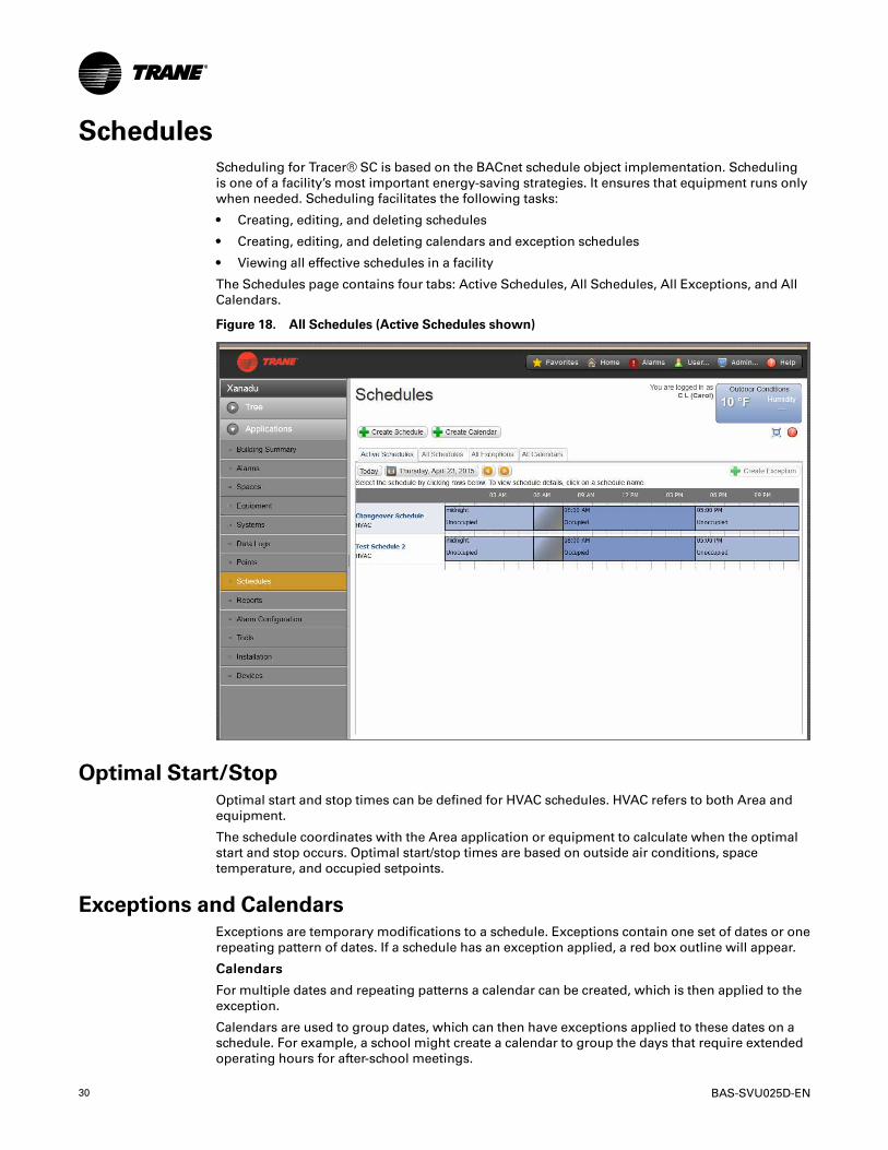
SchedulesScheduling for Tracer® SC is based on the BACnet schedule object implementation. Scheduling
is one of a facility’s most important energy-saving strategies. It ensures that equipment runs only
when needed. Scheduling facilitates the following tasks:
• Creating, editing, and deleting schedules
• Creating, editing, and deleting calendars and exception schedules
• Viewing all effective schedules in a facility
The Schedules page contains four tabs: Active Schedules, All Schedules, All Exceptions, and All
Calendars.
Figure 18. All Schedules (Active Schedules shown)
Optimal Start/StopOptimal start and stop times can be defined for HVAC schedules. HVAC refers to both Area and
equipment.
The schedule coordinates with the Area application or equipment to calculate when the optimal
start and stop occurs. Optimal start/stop times are based on outside air conditions, space
temperature, and occupied setpoints.
Exceptions and CalendarsExceptions are temporary modifications to a schedule. Exceptions contain one set of dates or one
repeating pattern of dates. If a schedule has an exception applied, a red box outline will appear.
CCaalleennddaarrss
For multiple dates and repeating patterns a calendar can be created, which is then applied to the
exception.
Calendars are used to group dates, which can then have exceptions applied to these dates on a
schedule. For example, a school might create a calendar to group the days that require extended
operating hours for after-school meetings.

BAS-SVU025D-EN 31
RReelleeaassee FFuunnccttiioonn
The release function is a predetermined time in which the present schedule or the event releases
control over to the next event based on priority. Conceptually, a scheduled release is very similar
to a timed override. For example, after the daily schedule ends at 12:00 am (midnight), the
schedule releases control over to the next event.
Creating a ScheduleTracer SC leads you through the process of creating a schedule for your facility by navigating
through a series of steps and pages, often referred to as a "wizard." If you need help completing
the steps, click the help icon located on each page. You can create a schedule to control the
following points and applications based on time and date:
• Binary outputs and values
• Analog outputs and values
• Multistate outputs and values
• Equipment, spaces, and system applications (typically referred to as HVAC schedules).
Points and applications are referred to asmemberswhen they are assigned to a schedule.
Members can be assigned to only one schedule during the same effective period. Members must
be the correct type; that is, a binary point cannot be included in an analog schedule.
TToo ccrreeaattee aa sscchheedduullee::
1. Click the ccrreeaattee sscchheedduullee button.
The CCrreeaattee SScchheedduullee —— SScchheedduullee IInnffoorrmmaattiioonn page appears.
2. Enter a name for the schedule, and select the schedule type and effective dates.
3. Click nneexxtt to continue. The CCrreeaattee SScchheedduullee —— SSeelleecctt MMeemmbbeerrss page appears.
4. From the sseelleeccttiioonn ttrreeee, select members (spaces and areas) for the schedule, then click AAdddd
to move to sseelleecctteedd iitteemmss.
5. Click nneexxtt to continue. The CCrreeaattee SScchheedduullee –– SScchheedduullee TTiimmeess ppaaggee aappppeeaarrss..
6. Select a schedule default. Each day is independent of the others and always begins with the
sscchheedduullee ddeeffaauulltt value. The schedule default value is applied to each day of the week and is
the value that the schedule defaults to at 12:00 a.m. for any given day. Select RReelleeaassee (see
below), Occupied, or Unoccupied.
NNoottee:: A RReelleeaassee is a predetermined time in which the present schedule or the event releasescontrol over to the next event based on priority. A scheduled Release is very similar to atimed point override.
7. Add events to the schedule: click add event, which opens the event dialog box.
8. Enter a time for when the event will start and select a value.
9. Enter a time for when the event will stop (this is optional).
10. Select the days of the week to which the event will be applied.
11. Click Add. The event appears in the schedule viewer. (To edit or delete an event, click on the
event in the schedule viewer.)
12. Click nneexxtt to continue. The CCrreeaattee SScchheedduullee –– SSuummmmaarryy page appears.
13. Review the schedule. Click finish to save the new scheduled as summarized.
SScchheedduulleess

32 BAS-SVU025D-EN
PointsIn an automated building control system, points are the building blocks used to create a control
system. They are used in setpoints, controlling outputs on a device, reading the values of
hardware inputs and holding calculated data. In addition, points provide the only means to
generate and route alarms to the event log.
Tracer® SC defines points in two ways:
UUsseerr--ddeeffiinneedd: You can create points to use, for example, with a TGP program or to monitor a
temperature for a building.
SSyysstteemm--ddeeffiinneedd: These points are created when you create an Area, a VAS, and when you install
equipment or spaces.
Points TypesTracer® SC classifies points according to one of three types (analog, binary, multistate) and one
of three functions (input, output, value). In total, there are nine point types:
• Analog inputs—These are typically values such as room temperature or air flow pressure
generated by a sensor or device. Inputs points obtain their value from a selected referencer.
Input points are typically used to read values from other controllers such as LonTalk devices
or unit controller input points.
• Analog outputs—These are used to control devices such as damper actuators or water valves,
or to provide setpoints to control other devices. Analog outputs can be controlled and
overridden by using priority control.
• Analog values—These are points that have real number values. Analog values do not contain
referencers but can be controlled and overridden by using priority control. Value points are
typically used for calculated values or setpoints.
• Binary inputs—These are typically two-state inputs, such as on/off or alarm/normal. Binary
inputs are generated by switching devices. Inputs points obtain their value from a selected
referencer. Input points are typically used to read values from other controllers such as
LonTalk devices or unit controller input points.
• Binary outputs—These points are typically used to turn devices on or off. Binary outputs can
be controlled and overridden by using priority control.
• Binary values—These points can only be true or false. Binary values do not contain
referencers but can be controlled and overridden by using priority control. Value points are
typically used for calculated values or setpoints.
• Multistate inputs—Multistate points have between 1 and 20 states. Text is displayed for each
state rather than a numerical value. Inputs points obtain their value from a selected
referencer. Input points are typically used to read values from other controllers such as
LonTalk devices or unit controller input points.
• Multistate outputs— Multistate points have between 1 and 20 states. Text is displayed for
each state rather than a numerical value. Multistate outputs can send their values to a defined
referencer and can be controlled and overridden by using priority control. Multistate outputs
are typically setpoints that are sent to controllers such as occupancy or heat cool mode
request on LonTalk controllers.
• Multistate values—Multistate points have between 1 and 20 states. Text is displayed for each
state rather than a numerical value. Multistate values do not contain referencers but can be
controlled and overridden by using priority control. Multistate values are typically calculated
values in controllers or applications such as such as occupancy status or heat cool mode
status.

BAS-SVU025D-EN 33
Point OverridesAn override refers to the action of a user taking control of a point rather than allowing the system
to control it. Point values can be overridden for output and value points by users who have been
assigned a priority level that gives them override capability. Priority levels of 1–16 exist, with 1
being the highest. The following four priority levels have been pre-assigned for user overrides:
• 1: Life Safety - Manual
• 8: Manual Override High
• 11: Manual Override Medium
• 13: Manual Override Low (the default for user overrides)
A user with a priority level higher than 13 has advanced override capability.
Overrides take place based on a user’s priority level. If a user with a higher priority level has
performed an override, an override entered by a user with a lower priority level will not take
effect until the entry by the higher priority user clears.
Points appearing with the following icon on their right can be overridden: .
A point that has been overridden appears with the following icon:
• A user override exists:
• A temporary user override exists:
Performing Simple OverridesThe simple override feature uses a priority level of 13 —Manual Override Low.
TToo ppeerrffoorrmm aa ssiimmppllee oovveerrrriiddee ooff aann oouuttppuutt oorr vvaalluuee ppooiinntt::
1. Begin at one of the following pages:
• For a point, begin at the page containing the list of points of that type.
• For the occupancy mode of a point, begin at the status page for the specific equipment.
• For a space or equipment setpoint, begin at the status page for the specific equipment,
then click the ccoonnffiigguurree button to open the CCoonnffiigguurraattiioonn page.
2. Select the override icon ( ) to the right of the point. The simple override page appears.
Select or enter a point value, with or without an expiration time.
3. Click SSaavvee.
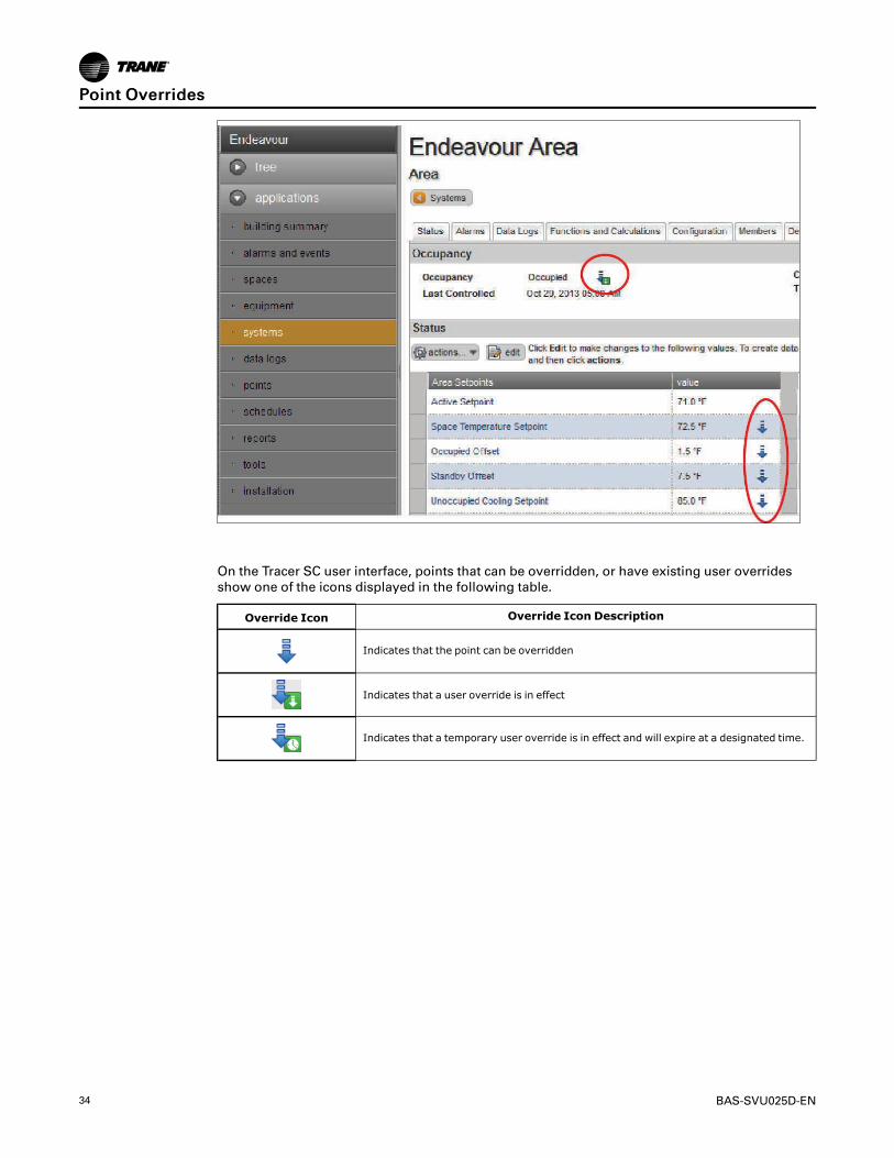
34 BAS-SVU025D-EN
On the Tracer SC user interface, points that can be overridden, or have existing user overrides
show one of the icons displayed in the following table.
Override Icon Override Icon Description
Indicates that the point can be overridden
Indicates that a user override is in effect
Indicates that a temporary user override is in effect and will expire at a designated time.
PPooiinntt OOvveerrrriiddeess

BAS-SVU025D-EN 35
SystemsTracer® SC supports three system applications:
• Area
• Variable Air Systems (VAS)
• Chiller Plant Control (CPC)
The individual pages for each system component allow you to view status, configure the system
and its functions, and to view and add members.
Area ApplicationArea is an application that resides on the Tracer® SC. The primary function of Area is to
coordinate the start and stop of equipment based on a schedule stored in the Tracer SC. An Area
may consist of a single room, a group of rooms, a large open warehouse, a manufacturing space,
or any grouping defined by a system user. Area allows such functions as synchronizing member
setpoints and controlling a large number of devices to be performed as one efficient operation.
Area can be configured to use multiple algorithms, along with area temperatures and humidity
inputs, to make an economizing decision.
Area also supports:
• Optimal start/stop
• Humidity pulldown
• Night purge
• Unoccupied heating/cooling setpoints
• Unoccupied humidify/dehumidify
• Timed override functions
Additionally, the Area application allows users to efficiently perform a single operation, such as
changing a setpoint, creating a schedule, performing an override, and apply it to all members of
the area. For more information, see the Air Systems for Tracer SC Applications Guide, (BAS-APG007).
Variable Air Systems (VAS) ApplicationThe variable air system (VAS) coordinates the control of air handlers, rooftop units, and variable
air volume terminal units. The Tracer® SC VAS includes valuable tools to help manage tasks that
were previously problematic and time consuming, such as:
• Determining Heat/Cool mode for changeover systems
• Coordinating AHU and VAV box operation
• Commissioning VAV boxes
• Scheduling common spaces
• Optimizing ventilation
• Optimizing duct static pressure
For more information, see the Air Systems for Tracer SC Application Guide, (BAS-APG007).
Chiller Plant Control (CPC) ApplicationThe Chiller Plant Control (CPC) application coordinates chillers and provides system chilled water
control.
The CPC application allows you to configure a chiller plant for optimal efficiency and reliability,
and provides a means for you to monitor and control the daily operation. Depending upon the
many possible chiller plant configurations and design differences, the CPC application can:
• Provide overall chiller plant status information and alarms to local and remote Tracer® SC
users.
36 BAS-SVU025D-EN
• Enable or disable chiller plants.
• Start, stop, and monitor the status of system chilled water pumps.
• Calculate individual chilled water setpoints for individual chillers in series chiller plants
• Request when chillers are added or subtracted according to building load requirements and
user-specified add and subtract logic
• Rotate chillers according to user-defined intervals
• Remove chillers from the rotation in the event
For more information, see the Chiller Plant Application Guide, (BAS-APG012).
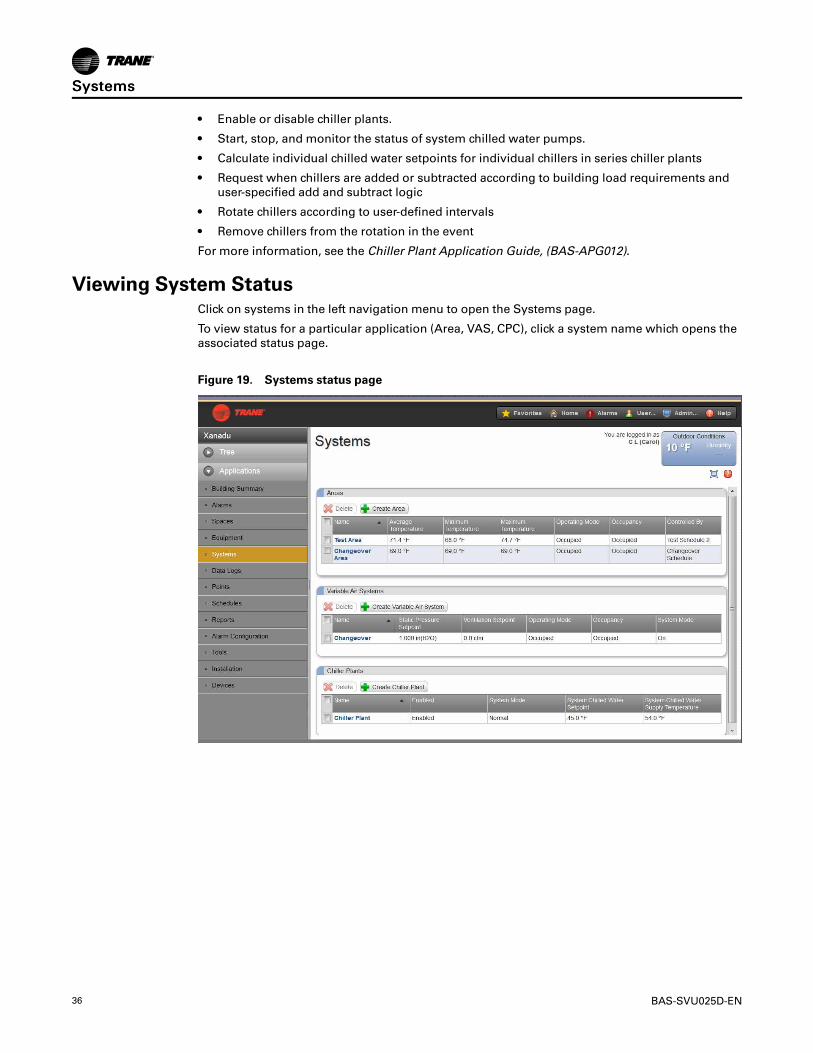
Viewing System StatusClick on systems in the left navigation menu to open the Systems page.
To view status for a particular application (Area, VAS, CPC), click a system name which opens the
associated status page.
Figure 19. Systems status page
SSyysstteemmss

BAS-SVU025D-EN 37
The Tools MenuTo effectively manage your Tracer® SC, a selection of task-based tools are available. The
following tools described in this section are accessible from the Tools page:
• Backup and Restore
• Custom Graphics
• Global Referencers
• Programs
• User Equipment Keys
• Equipment Templates
• System Logs
• Tracer ES IPAddress
• Resource Usage
• BACnet Information
Figure 20. Tools menu
Backup and RestoreFrom the left navigation menu click TToooollss >> BBaacckkuupp aanndd RReessttoorree. Backup and Restore is a
process that involves creating an exact duplication of a Tracer® SC, exporting (saving) the
duplicated copy, and then restoring that copy at a later time. Use the Restore tool to restore the
Tracer SC system configuration file that was produced by the backup tool. It is important to back
up Tracer SCs in the event that a system failure occurs. Backups should also be performed prior
to upgrading software, adding devices, or adding new applications. Follow best practices when
implementing a backup and restore procedure plan for your system. Backups do not include IP
settings or the license file. New in Tracer SC V4.1 is the option to schedule backups on a regular
basis.
IImmppoorrttaanntt:: Regarding SD cards: If an SD card has been installed in the Tracer SC, it will store thebackup on the SD card rather than its internal memory. The SD card must supportSDHC. SDHC has a maximum size of 32 GB. SD cards that exceed 32 GB will notwork.

38 BAS-SVU025D-EN
Custom GraphicsYou can use custom graphics in the Tracer® SC user interface to view and navigate through the
building automation system. Custom graphics can be used as your home page, as status pages,
and can be associated with the customized navigation tree.
Custom graphics can display data related to building environments, such as climate, lighting, and
other controllable operations, and can be used to change setpoints and override equipment
operation.
CCrreeaattiinngg CCuussttoomm GGrraapphhiiccss
Use the Tracer Graphic Editor (TGE) to create custom graphics. For instructions on creating
custom graphics, see the Tracer Graphics Editor Applications Guide (BAS-APG020).
NNoottee:: TGE is a component of the Tracer TU service tool and is launched from a Tracer TU menuitem. To obtain the Tracer TU installation file, go to the Service Technicians page on theTrane portal. See the Tracer TU Service Tool Getting Started Guide (TTU-SVN01) forreference.
DDeelleettiinngg CCuussttoomm GGrraapphhiiccss ffrroomm TTrraacceerr SSCC
On the CCuussttoomm GGrraapphhiiccss page, select the graphic(s) you want to delete. From the AAccttiioonnss
button, select DDeelleettee.
Global ReferencersA global reference is a connection that is made between a data point in the Tracer® SC and one
or more systems that are configured to respond to the value of the data point. A global reference
is made up of one trigger and one or more targets. It allows you to read a piece of data from one
place and then send to one or more places. Global references can be made to a point in the
Tracer SC or to external points of BACnet MS/TP equipment.
From the left navigation menu click TToooollss > GGlloobbaall RReeffeerreenncceerrss.. The Global Referencers list
page serves as a starting point for additional options.
Beginning with version 4.3, passing data from one Tracer SC to another has been simplified
when creating a global referencer as described below:
1. Click CCrreeaattee GGlloobbaall RReeffeerreenncceerr. The CCrreeaattee GGlloobbaall RReeffeerreenncceerr —— SSeelleecctt SSoouurrccee dialog
box opens.
2. Click SShhooww ootthheerr SSCCss oonn tthhee nneettwwoorrkk, which populates the SSeelleecctt SSoouurrccee window with the
other Tracer SCs.
3. From there, select the equipment or point for reference.
4. Click NNeexxtt to continue.
Figure 21. Create global referencer — show other SCs on network
TThhee TToooollss MMeennuu

BAS-SVU025D-EN 39
ProgramsTracer Graphical Programming (TGP) programs are created and downloaded to the Tracer® SC
by using the Tracer TU service tool. To view the status of programs after they have been
downloaded to the Tracer SC, select TToooollss > PPrrooggrraammss from the left navigation menu. The
PPrrooggrraammss list page shows the how often programs in the Tracer SC run and the most recent run
time.
NNoottee:: See the Tracer TU Service Tool Getting Started Guide (TTU-SVN01).
System LogsSystem logs that are currently on the system are available for viewing or exporting. System logs
can be the standard “hydra” log files (hydra.log, hydra.log.0, hydra.log.1, hydra.log.2, hydra.
log.3, hydra.log.4), any stack dump log files (stackdump.log.x), or any additional log files that
may be generated by a Tracer SC application and/or process.
From the left navigation menu click TToooollss >> SSyysstteemm LLooggss.
Tracer Ensemble IPAddressThis tool only applies to facilities with Tracer Ensemble installed. You can view and edit the Tracer
Ensemble IP address for Direct Linking. To access, select TToooollss >> TTrraacceerr EEnnsseemmbbllee IIPPAAddddrreessss
from the left navigation menu.
Resource UsageResource Usage displays system usage among applications, memory, and points. This is
primarily used by Trane Technical support.
BACnet InformationInformation about BACnet configurations is shown on this page. This information is typically
used by Trane Technical Support.
TThhee TToooollss MMeennuu

40 BAS-SVU025D-EN
Unit ControllersThis section provides information about unit controllers that Tracer® SC supports and
procedures for installing, replacing, and retrofitting.
Trane Unit Controllers Supported by Tracer SCThe following table lists all Trane LonTalk and BACnet devices supported by Tracer SC.
Table 4. LonTalk, BACnet devices, and equipment supported by Tracer SC
LonTalk BACnet
CH530 (LCI-C) Chiller Equipment (BCI-C)
CH532 (EMEIA only) IntelliPak™ I or II equipment (BCI-I)
IntelliPak™ I or II equipment (LCI-I) VAV equipment (Tracer UC400 unit controllers)
ReliaTel™equipment (LCI-R) Tracer UC400 programmable unit controller
Voyager™equipment (LCI-V) Tracer UC400 blower coil
VAV equipment (Tracer VV550/551 unit controllers) Tracer UC400 Variable Speed Water Source Heat Pump (WSHP)
Tracer UC800 controller for AdaptiView™ Tracer UC400 2 Heat/2 Cool
Tracer ZN510/511 unit controller Tracer UC400 Fan Coil
Tracer ZN520/521 unit controller Tracer UC600 programmable unit controller
Tracer ZN523 zone controller Tracer UC800 controller for AdaptiView™
Tracer ZN517 unitary controller ReliaTel™ equipment (BCI-R)
Tracer ZN524 unit controllerCommunicating thermostats for rooftop units, heat pumps, and fancoil applications
Tracer ZN525 zone controller
Tracer MP501 multi-purpose controller
Tracer MP503 input/output module
Tracer MP580/581 multi-purpose unit controller
Tracer AH540/541 controller
TraneTR200 Variable Frequency Drive (VFD)
WAGO High Density I/O module (third-party)
Unit Controllers (Comm3/4) Supported by Tracer SC Through theLegacy Communications Bridge
The following Comm 3/4 devices are supported by Tracer SC through the Legacy
Communications Bridge. For more information, refer to the Tracer Communications Bridge —Comm 3/4 to Tracer SC Setup and Configuration Guide, (BAS-SVX064).
• VAV II,III,IV
• VAV I
• IntelliPak
• Voyager
• Commercial self-contained (CSC)
• TCMs (non-slave)
• PCMs, UPCMs, and TUCs

BAS-SVU025D-EN 41
Trane Legacy Comm Chillers Support by Tracer SC• Centrifugal Chillers (UCP2)
• Helical Rotary Chillers (UCP2)
• CGx Chillers
• Series-R Chillers (RTA/RTW)
Non-Trane Unit controllers Support by Tracer SCFor a list of non-Trane LonTalk and BACnet controllers supported by Tracer SC, visit the Trane.
com Commercial product page at http://www.trane.com/COMMERCIAL/Internal/View.aspx?i=
2757 and open the Tracer SC Integration Capabilities link.
Or, contact St. Paul Trane Product Support for updated procedures to determine the risks
associated with integration to a particular device.
Quantity of Unit Controllers Supported by Tracer SCEach Tracer SC can support a maximum quantity of 240 unit controllers. Unit controllers installed
on a Tracer SC can be a combination of BACnet and LonTalk unit controllers.
NNootteess::
• Scalable 15-device licenses available.
• A maximum of 120 wireless devices are supported in a single Tracer SC facility and240 in a multiple Tracer SC facility.
• LonTalk devices must be physically installed on the Tracer SC-App.
• BACnet UCs can be physically connected on the Tracer SC-App or a Tracer SC-Base(maximum of 120 devices).
• Tracer UC600s cannot exceed 10 per MS/TP link or a total of 20 per Tracer SC system.
UUnniitt CCoonnttrroolllleerrss

42 BAS-SVU025D-EN
LEDs and the 7–Segment DisplayThis section describes how to interpret the activity of the Tracer® SC LEDs and the 7–segment
display.
Powering Up/Powering Down the Tracer SCTo power up the Tracer SC, press the power button.
All LEDs illuminate and the following sequence flashes on the 7-segment display: 8, 7, 9*, 5, 4, L,
dancing dash pattern. The dancing dashes persist while the Tracer SC is operating normally.
NNoottee:: 7-segment 6 was changed to 9 to indicate the new boot file had been successfully applied.
To power down the Tracer SC, press the power button. The 7-segment display performs a shut-
down sequence (3, -, 2, -, 1, -) before the Tracer SC powers down.
The LEDs and the 7–Segment DisplayThe LEDs and the 7-segment display on the Tracer SC indicate the operation and communication
status of the Tracer building automation system. The following figure and the corresponding
table show their locations on the front of the controller.
Figure 22. Location of the LEDs and the 7–segment display on Tracer SC
Callout Number inFigure Description
1 Power button
2 LonTalk communication LEDs
3 BACnet MS/TP link 1 communication LEDs
4 BACnet MS/TP link 2 communication LEDs
5 EIA-232 LEDs
6 IMC LEDs
7 Status LED
8 Ethernet 2 LEDs
9 Ethernet 1 LEDs

BAS-SVU025D-EN 43
Callout Number inFigure Description
10 7-segment display
11 LonTalk service pin
12 LonTalk service LED
Interpreting the LEDsThe following table identifies the LEDs and interprets their activity.
Table 5. LED identification and interpretation
LED type LED activity Indicates...
Status
On steady (green) Power reception
Flashing (red), and an “F” appears on the7-segment display followed by a code Fatal error. Service required.
Flashing (red), and an “H” appears on the7-segment display followed by a code Hardware failure. SC will probably need to be replaced.
Link 1 communicationL1 TX flickers (green) Data transmission
L1 RX flickers (yellow) Data reception
Link 2 communicationL2 TX flickers (green) Data transmission
L2 RX flickers (yellow) Data reception
LonTalk communicationLon TX flickers (green) Data transmission
Lon RX flickers (yellow) Data reception
LonTalk service On steady (red)
LonTalk service pin has been pressed:
• Short press–broadcast neuron ID and program IDidentifies itself so Rover can assign it a DSN.
• Long press (more than 15 sec.)–Forces the SC LONnode to an unconfigured state and disables LonTalkuntil reconfigured with Rover.
|O|O| [EIA-232 serial connection]IOIOI TX (green) Data transmission
IOIOIO RX (yellow) Data reception
IMCIMC TX (green) Data transmission
IMC RX (yellow) Data reception
Ethernet 1, Ethernet 2LINK on steady (green) Valid Ethernet connection
ACT flickers (yellow) Data transmission and reception
Interpreting the 7–Segment DisplayThe 7–segment display shows the operating status of the Tracer SC as described in the following
table.
Table 6. 7-segment display: Codes and interpretation
Red/Green LED 7-segment display Indicates...
Green 8Processor in reset, or no functioning software. A persistent “8” meansthat service is required.
Green 7 Starting level 1 boot loader
Green 9 Starting level 2 boot loader
LLEEDDss aanndd tthhee 77––SSeeggmmeenntt DDiissppllaayy

44 BAS-SVU025D-EN
Table 6. 7-segment display: Codes and interpretation (continued)
Red/Green LED 7-segment display Indicates...
Green 5Entering operating system. A persistent “5” means the operatingsystem is malfunctioning.
Green 4 (this number remains for a few seconds) Booting operating system.
Green –L Loading and initializing main program.
Green“Dancing dash” dashes flash one at atime: top, middle, bottom Normal operation
Green3, -, 2, -, 1, -(sequence repeats)
Power button was pressed and Tracer SC is shutting down. May take10 or more seconds.
Green3, 2, 1(sequence repeats)
Main program shutting down due to reboot command. In most cases,the main program will be restarted.
Flashing Red 7 FMismatch between level 1 boot loader and hardware. Service isrequired.
Flashing Red 7 H Hardware failure. SC will probably need to be replaced.
Flashing Red 7 A Missing level 2 boot loader.
Flashing Red 7 U Mismatch between level 2 boot loader and hardware.
Green Single digit during operation Rotary switch was changed. The new setting of the changed switch isdisplayed on the 7-segment LED for several seconds.
U, P, d Firmware update is in progress.
d, o, n, E Updating of the operating system is finished. The Tracer SC can bepowered off, the SD card removed, and the Tracer SC restarted.
F, o, r, C, E Rotary switches set to 999; forced return to factory defaults inprogress.
C, L, E, A, r Tracer SC is restoring factory defaults (whether by force return, UIcommand, or at the beginning of a database restore operation).
r Database restore in progress.
Flashing Red H, O, L, d Main program is delayed due to multiple crashes (may take up to 4hours).
Red FCannot load operating system. May be remedied by SD-card updatewith appropriate software version.
Flashing Green UPower button was pressed when main programwas not running/notresponsive. SC is shutting down; wait for LEDs to turn off.
NNoorrmmaall ssttaarrttuupp sseeqquueennccee:: 8, 7, 9, 5, 4, -L, dancing dashes
SShhuuttddoowwnn sseeqquueennccee:: Press power button. LED displays 3, -, 2, - 1 - until the application shuts
down. Press the power button to turn power off.
LLEEDDss aanndd tthhee 77––SSeeggmmeenntt DDiissppllaayy

BAS-SVU025D-EN 45
TroubleshootingThe following troubleshooting suggestions are meant to help resolve most common problems
associated with the Tracer® SC. If you are unable to resolve a problem, contact a qualified Trane
service technician or the Trane Product Support team.
Troubleshooting with LEDs and the 7-Segment DisplayThe LEDs and the 7-segment display can be used for troubleshooting. Refer to the following table
for causes and resolutions to specific LED displays.
Event Probable cause Resolution
7-segment display sequence does not followthe start-up sequence May indicate a failure of the Tracer SC.
To reset the Tracer SC, press the powerbutton to shut down, and then press again torestart. Contact the Trane Product Supportteam if this does not solve the problem
F code displays on the 7-segment display Indicates a fatal error. Contact the Trane Product Support team forassistance.
H, o, L, D displays on the 7-segment displayThis code indicates that a recoverable error ispresent, and is waiting to restart. The restartprocess may take up to four hours.
Contact the Trane Product Support team ifyour Tracer SC does not restart after themaximum four hour period.
Ethernet LINK LED is not illuminated This indicates that the Tracer SC is notconnected to Ethernet.
Check all cables and connections. It may bepossible that the Ethernet cable is notworking. Attempt to resolve by replacing theEthernet cable.
Ethernet ACT LED is not illuminated This indicates that communication does notexist between the Tracer SC and Ethernet.
Verify that the IP address you have entered iscorrect.
Red status LED along with an F code or H codeon the 7-segment display Contact the Trane Product Support team
Status LED is unlit. The Tracer SC is not receiving power. Verify that the power supply is functioningproperly.
LonTalk Service LED is red
Note: Upon startup, the LonTalk LED ismomentarily red and is not a cause foralarm.
Contact the Trane Product Support team.
7-segment display shows 3, 2, 1 and thenlower-left, upper-right in sequence
Indicates that the application is shuttingdown and not restarting.
Attempt to resolve the problem by cyclingpower to the SC. If it recurs, contact the TraneProduct Support team.
Force Return to Factory DefaultsIn some cases, a corrupt database or similar problem may prevent you from accessing the Tracer
SC user interface in order to return to factory defaults.
If this occurs, do the following to return to factory defaults:
1. Power down the Tracer SC.
2. Reset the rotary switches to “999.”
3. Power up the Tracer SC.
The 7-segment display shows F, o, r, C, E.
4. Within 30 seconds, set the rotary switches to the intended normal value.
The 7-segment display shows C, L, E, A, r, indicating that the database is being cleared. It will
then resume normal operation showing –L on the 7-segment display during startup and then
“dancing dashes.”
NNoottee:: If rotary switches are not reset within 30 seconds, the Tracer SC will power downleaving the database intact.

46 BAS-SVU025D-EN
Troubleshooting Network ConnectionsTroubleshoot network connections to a Tracer SC by using the following tools and procedures.
PINGPING is a PC utility that is provided with every Microsoft operating system. You can use it to
verify the connectivity between two devices on an IP network.
To perform the test:
1. Select SSttaarrtt >> RRuunn..
2. In Run, type ppiinngg followed by the IP address of the device you want to verify connection with.
Click Enter.
You will receive a message with either a positive or negative response. A positive response to
PING, but a negative response to the Web browser may indicate a problem with proxy
settings, IP addressing, or network communication.
IPCONFIGIPCONFIG is a software program that is provided with every Microsoft operating system. It
identifies all of the configured connections for your PC. Use this tool to verify your connection
settings.
To perform the test:
1. Select SSttaarrtt >> RRuunn..
2. In Run, type ccmmdd. Click Enter.
3. In the cmd/exe window, type iippccoonnffiigg//. Click EEnntteerr.
You will receive a detailed list of all hardware and software connections and their settings.
TTrroouubblleesshhoooottiinngg

BAS-SVU025D-EN 47
NNootteess

NNootteess
Ingersoll Rand (NYSE:IR) advances the quality of life by creating comfortable, sustainable and efficient environments.
Our people and our family of brands—including Club Car®, Ingersoll Rand®, Thermo King® and Trane®—work together
to enhance the quality and comfort of air in homes and buildings; transport and protect food and perishables; and
increase industrial productivity and efficiency. We are a global business committed to a world of sustainable progress
and enduring results. For more information, visit www.ingersollrand.com.
Ingersoll Rand has a policy of continuous product and product data improvements and reserves the right to change design and specifications without notice.
©2016 Ingersoll Rand All rights reserved
BAS-SVU025D-EN 05 Oct 2016
Supersedes BAS-SVU025C-EN (September 2016)
We are committed to using environmentally
conscious print practices that reduce waste.