DAI Shi-jie and HUANG-He The robotic visual information
32
The robotic visual information processing system based on wavelet transformation and photoelectric hybrid 373 X The robotic visual information processing system based on wavelet transformation and photoelectric hybrid DAI Shi-jie and HUANG-He School of Mechanical Engineering, Hebei University of Technology, Tianjin 300130, China; [email protected]. 1. Introduction There are mainly two outstanding characteristics for the developing trend of robotics: on one hand, the robotic application fields expand gradually and robotic species increase day by day; on the other hand, the robotic performance improves constantly, gradually developing towards intellectualization. To make robots have intelligence and reactions to environmental changes, first of all, robots should have the abilities of environmental perception, so using sensors to collect environmental information is the first step for robotic intellectualization; secondly, the significant embodiment of robotic intellectualization is how to deal with the environmental information gained by sensors comprehensively. Therefore, sensors and their information processing systems complement each other, offering decision-making basis to robotic intelligent work [1] . So the intelligent feature of intelligent robots is its interactive ability with external environment, where the visual, tactile, approaching and force sense have great significance, especially the visual sense which is deemed to be the most important one. Sensor-based robotic intelligent engineering has become a significant direction and research focus [2-5] . Vision is one of the most important senses for human being. Over 70% information obtained from external environment for human is done by vision, so visual information processing is one of the core tasks for current information researches. Human eyes collect massive information from their environment, and then according to knowledge or experience, the cerebrum fulfills the processing work such as machining and reasoning so as to recognize and understand surrounding environment. Likewise, robotic vision is to install visual sensors for robots, simulating human vision, collecting information from image or image sequence and recognizing the configuration and movement of objective world so as to help robots fulfill lots of difficult tasks [6] . In industry, robots can auto-install parts automatically [7] , recognize accessories, track welding seams [8-11] , cut material willingly, and so on; in business, they can be utilized to patrol, track and alarm automatically [12-17] ; in the aspect of remote sensing, they can be used to survey, map and draw voluntarily. The visual devices of mobile robots could not only recognize indoor or outdoor scenery, carry out path tracking and 21 www.intechopen.com
Transcript of DAI Shi-jie and HUANG-He The robotic visual information

The robotic visual information processing system based on wavelet transformation and photoelectric hybrid 373
The robotic visual information processing system based on wavelet transformation and photoelectric hybrid
DAI Shi-jie and HUANG-He
X
The robotic visual information processing system based on wavelet transformation
and photoelectric hybrid
DAI Shi-jie and HUANG-He School of Mechanical Engineering, Hebei University of Technology, Tianjin 300130,
China; [email protected].
1. Introduction
There are mainly two outstanding characteristics for the developing trend of robotics: on one hand, the robotic application fields expand gradually and robotic species increase day by day; on the other hand, the robotic performance improves constantly, gradually developing towards intellectualization. To make robots have intelligence and reactions to environmental changes, first of all, robots should have the abilities of environmental perception, so using sensors to collect environmental information is the first step for robotic intellectualization; secondly, the significant embodiment of robotic intellectualization is how to deal with the environmental information gained by sensors comprehensively. Therefore, sensors and their information processing systems complement each other, offering decision-making basis to robotic intelligent work[1]. So the intelligent feature of intelligent robots is its interactive ability with external environment, where the visual, tactile, approaching and force sense have great significance, especially the visual sense which is deemed to be the most important one. Sensor-based robotic intelligent engineering has become a significant direction and research focus[2-5]. Vision is one of the most important senses for human being. Over 70% information obtained from external environment for human is done by vision, so visual information processing is one of the core tasks for current information researches. Human eyes collect massive information from their environment, and then according to knowledge or experience, the cerebrum fulfills the processing work such as machining and reasoning so as to recognize and understand surrounding environment. Likewise, robotic vision is to install visual sensors for robots, simulating human vision, collecting information from image or image sequence and recognizing the configuration and movement of objective world so as to help robots fulfill lots of difficult tasks[6]. In industry, robots can auto-install parts automatically[7], recognize accessories, track welding seams[8-11], cut material willingly, and so on; in business, they can be utilized to patrol, track and alarm automatically[12-17]; in the aspect of remote sensing, they can be used to survey, map and draw voluntarily. The visual devices of mobile robots could not only recognize indoor or outdoor scenery, carry out path tracking and
21
www.intechopen.com
Robot Vision374
autonomous navigation, and fulfill tasks such as moving dangerous materials, detecting field rearward situation of enemy, sweeping landmine in enemy areas, and so on[18-24], but also automatically watch military targets, judge and track moving targets. Therefore, without visual systems, it is hard for robots to response to surrounding environment in an intelligent and sweet way. In general, robotic vision means industrial visual systems operating together with robots, and its several basic issues include image filtering, edge feature extraction, workpiece pose determination, and so on. By means of introducing visual systems into robots, the operational performance of robots is extended greatly, which makes robots have a better adaptability to complete tasks. Besides satisfying low price, robotic visual systems should also meet demands such as good discrimination abilities towards tasks, real-time performance, reliability, universality, and so on. In recent years, the studies on robotic vision have become a research focus in robotic field, and many different solutions to improve the performance of visual systems are proposed in succession[25-26]. Of course, these solutions unavoidably require a higher demand on visual system and data processing ability on computers, especially real-time performance which is called more difficulties. An important characteristic of robotic visual system is that its information data amount is large, and it demands a high processing rate to meet real-time controlling. Although the operation speed of resent computers has been very high, the information transmission and processing rate still can not satisfy the robotic real-time perceptual system. So processing rate is a bottleneck of robotic visual system urgently needing to be resolved based on practical purpose. At present, many researches are devoting into this problem, whose methods mainly include perfecting computer program, adopting parallel processing technology based on Transputer or optical information processing technology to improve image processing rate.
1.1 Design of robotic visual system based on photoelectric hybrid Image feature extraction is one of the research emphases in robotic visual fields. People used to utilize various software algorithms to do this. Recently, along with the improvement of computer performance and the present of high performance algorithm, the processing rate of image feature extraction is raised greatly, but it still can not meet the real-time demand. For this reason, the photoelectric hybrid method is designed to realize robotic visual system. Optical information processing indicates using optical methods to realize various transformations or treatments to the input information. Optical image information can be treated by optical methods. According to mathematics, the function of optical lens to luminous beam can be seemed as one kind of Fourier transformation. A serious of Fourier transformation theorems all have their correspondences in optical diffraction phenomena. The function of Fourier transformation is to separate the mixed information of images in frequency domain in order to treat it in spatial frequency spectrum, that is the basic principle of optical information processing. According to cohence between time and space of the using illuminant, optical information processing can be divided into coherent optical information processing, incoherent optical information processing and white light optical information processing. Coherent optical information processing is commonly used, because its processing abilities are more flexible and varied than incoherent optical information processing.
www.intechopen.com

The robotic visual information processing system based on wavelet transformation and photoelectric hybrid 375
Making full use of optical functions such as large-capacity, fast response and parallel processing, two-dimensional optical processing get widely used. However, it has some inherent defects: firstly, a pure optical processing is hard to program. Although a pure optical system to complete certain tasks can be designed, it can not be used in some situations needing flexibility; secondly, optical system based on Fourier transformation is a simulation system, so it can not reach high precise; moreover, optical system can not make judgment, but some electronic system can do this. Even the simplest judgment is based on the comparison between output value and storage value, which can not realize without electronics. In addition, the weakness of the optical system just stresses the advantages of the electronic system, for example, accuracy, controllability and programmability are all the characteristics of digital computers. Therefore, the idea that combining the optical system to the electronic system is very natural. By means of this approach, the optical quick processing and parallelism is widely used.
1.2 Hybrid optical signal processing system Optical spectrum analysis systems, optical filtering systems and other optics-related systems have in common that they all perform two-dimensional processing at the same time and have simple structures. However, compared with computer data processing system, there are two drawbacks with them: Firstly, low accuracy, which is determined by the quality of optical system, especially by the photosensitive materials used to manufacture the filters; secondly, poor flexibility. Once the image types change, it is necessary to make their corresponding filters, and it is better to make them in the same device to get a better effect. The speed of current computer processing system is low and two-dimensional images contain a large amount of information, so it is necessary to get a high-speed and large-capacity computer to meet these requirements. But even with such advanced computer, it still can not meet the needs of real-time control. Therefore, when two methods combine, both of them can learn from each other and supplement each other. According to the characteristic of optical fast property, the image can be preprocessed to get a low accuracy one with little information. With this input, the computer capacity and its processing time can be greatly reduced, thus the requirements of real-time systems are met. With the development of national economy, scientific technology and national defense construction, information processing capacity and speed have been put forward higher and higher requirements. Because of optical information processing and optical computing with faster processing speed, large flow information and many other features, it has become an important research field in modern optical systems. These characteristics of optical information processing system are attributed to its use of light (light waves) as information carriers. First of all, just as other electromagnetic waves, the light waves also have a number of physical parameters, such as amplitude, phase, frequency, polarization state, and so on, and they can be modulated to carry information. Then, light has high frequency up to 3.9-7.51014Hz in the visible light range, which allows the transmitted signals to have great bandwidth. In addition, the light has a very short wavelength and fast spreading speed in the range of 400-760nm among the visible light range, together with the principle of independent propagation of light wave, it can transfer two-dimensional information distributed in the same plane to another surface with high resolution capacity via optical system, so as to provide conditions for two-dimensional “parallel” processing.
www.intechopen.com

Robot Vision376
Making full use of the optical large capacity and parallel processing capabilities, two-dimensional optical processing has gained a wide range of applications. The particular interesting applications are the processing of the image correlation in pattern recognition, image subtraction used in robotic vision and digital processing adopted in optical computing. Although optical correlator based on the general holographic filtering technique has already put forward for a long time, the concept of programmability in optical signal processing is introduced recently. Owing to the latest developments of perfect spatial light modulator and the photorefractive crystal, various real-time hybrid optical signal processing system (microcomputer-based optical processor) can be established. The first way to realize microcomputer-based optical processors is to use 4f (f denotes focal length) optical processing devices, the importation and spatial filter of which are produced by the programmable Spatial Light Modulator ( SLM ), as shown in fig.1. Programmable complex conjugate Fourier transform of the reference pattern is generated by microcomputer on SLM2. Consequently, CCD detector array can be used to detect the cross correlation between importation and reference pattern, then the detected signals can give a feedback to the microcomputer used for display and judgment. It is evident that if there is enough Spatial Bandwidth Product ( SBP ) and resolution for SLM to show the plural spatial filter generated by computer, a programmable real-time optical signal processors can be realization in 4f structures.
1. Object; 2.CCD camera; 3. Microcomputer; 4. CCD detector array; 5. Fourier transform lensL2; 6.SLM2; 7. Fourier transform lensL1; 8.SLM1; 9. Collimating lens; 10. Pinhole filter; 11.lasers Fig. 1. Optical processor based on computer The second way to realize the mixed optical processors is to apply the structure of joint Fourier transform, the importation and spatial impulse response of which can be displayed in the input Spatial Light Modulator namely SLM1, as shown in fig. 2. For example, programmable spatial reference functions and importation can be produced side-by-side, so the Joint-transform Power spectrums (JTPS) can be detected by CCD1. Then, JTPS is displayed on SLM2, and the cross correlation between importation and reference function can be obtained in the back focal plane of the Fourier transform lens FTL2. From the above, it is easy to educe that real-time mixed optical processor can be achieved with joint transform structures.
www.intechopen.com

The robotic visual information processing system based on wavelet transformation and photoelectric hybrid 377
1. BS---Beam Splitter; 2. L---Collimating Lens; 3. FTL---Fourier Transform Lens Fig. 2. Joint transform processor based on computer Although hybrid optical structure functions of the 4f system and joint transform system are basically same, they have an important difference, that is the integrated spatial filter (such as Fourier holograms) has nothing to do with the input signal, but the joint power spectrum displayed on the SLM2 (such as joint transform filter) is related with the input signal. Therefore, non-linear filtering can be used in the 4f system, but in general not in joint transform system, which would leads to undesirable consequences (e.g., false alarm and low noise ratio of the output).
1.3 The optical realization of Fourier transform Fourier transform is one of the most important mathematical tools among numerous scientific fields (in particular, signal processing, image processing, quantum physics, and so on). From a practical point of view, when one considers the Fourier analysis, it usually refers to (integral) Fourier transform and Fourier series. 1.3.1 Fourier transform At first, look at the state in one-dimensional situation, suppose a signal as xg , and its Fourier transform can be defined as: dxifxxgfG )exp( (1)
Where, fG is called as Fourier transform or frequency spectrum of xg . If xg
denotes a physical quantity in a certain spatial domain, fG is the representation of this physical quantity in the frequency domain. Its inverse transform is defined as: dfifxfGxg )exp(
(2)
www.intechopen.com

Robot Vision378
In (1), the content of the component with the frequency f in xg is fG , x is a
time or space variable, and fG denotes the component content of time frequency or
spatial frequency. Equation (1) indicates that fG is the integral of the product of xg
and fxje 2 which denotes the index function of the simple harmonic motion or the plane wave, ranging from to + . Equation (2) indicates that xg can be decomposed into
a linear superposition of a series of simple harmonic motion or plane waves, while fG is the weight function in the superposition computing. Then, look at the state in two-dimensional situation, suppose a signal as yxg , , and its Fourier transform can be defined as:
dxdyvyuxiyxgvuG )](2exp[),(,
(3)
The inverse transformation of (3) is :
dudvvyuxivuGyxg )](2exp[),(,
(4)
The existence conditions of the transformation are as follows: 1. ),( yxg is absolutely integrable in the whole plane;
2. In the whole plane, ),( yxg only has a finite number of discontinuous points, and in any finite region only with a finite number of extremum; 3. There is no infinite discontinuous point with ),( yxg . The conditions mentioned above are not necessary. In fact, "physical reality" is the sufficient condition for transformation. But for most of the optical system, the function expressions of signals are two-dimensional. For optical Fourier transform, x and y are spatial variables, but u and v are spatial frequency variables.
1.3.2 Optical Fourier transform and f4 optical system Known from information optics, far-field diffraction has characteristics of Fourier transform. As the back focal planes of thin lens or lens group are equivalent to , it can be educed that any optical system having positive focal length should have the function of Fourier transform. In coherent optical processing system, what the system transfers and processes is the distribution information of complex amplitude of optical images, and in general the system meets the principle of superposition to complex amplitude distribution.
www.intechopen.com

The robotic visual information processing system based on wavelet transformation and photoelectric hybrid 379
L y
x
P1
L1 ηξ
P2
P3
L2
Y1
X1
f f f f Fig. 3. Optical filter system In physical optics, the Abbe - Porter experimental system is a coherent optical processing system: using all kinds of spatial filters to change the spectrums of objects and images so as to change the structures of images, that is to make optical processing for the input information (optical information). Seen from geometrical optics, the f4 optical system is an imaging system with two confocal lenses and its magnification is -1. In general, the f4 optical system (also known as dual-lens system) as shown in fig. 3 is often used to carry
on coherent optical processing: the output plane yx , is overlapped with the front focal
plane of FTL1, the input plane yx, is overlapped with the back focal plane of FTL2, and spectrum plane is located in the coincidence position of the back focal plane of FTL1 and the front focal plane of FTL2. Irradiate the object with collimating coherent light, and its frequency spectrum will appear in the frequency plane, that is, when the input plane is located in the front focal plane of Fourier transform lens FTL1, the accurate Fourier
transform of the object function ),(~ yxE can be get from the back focal plane of FTL1: dxdyyxiyxEvuE )(2exp),(~),(~
(5) Where fu , f ---coordinates of the back focal plane of FTL1. Because the back focal plane of FTL1 is overlapped with the front focal plane of Fourier
transform lens FTL2, the Fourier transform of the spectral function ),(~ yxE can be get from the back focal plane of FTL2: dudvvuivuEyxE ),(2exp),(~),(~
(6) Where fx , fy ---coordinates of the back focal plane of FTL2.
www.intechopen.com

Robot Vision380
Therefore, (5) is substituted into (6), and the result is shown as follows:
),(~),(),(~),(~ yxEdxdyyyxxyxEyxE
(7)
This equation shows that after twice Fourier transform, the final output image function of
the object function ),(~ yxE is same as its input image function, only being a reversed image. Coherent optical information processing is normally carried out in the frequency domain,that is, using various spatial filters to change the spectrum in the spectrum plane so as to change the output image to achieve the purpose of image processing. This kind of operation which changes the spectrum components is entitled “Spatial Frequency Filtering”, and “Spatial Filtering” for short. Based on the assumption that complex amplitude transmission coefficient of spatial filter
is
fv
fut ,~ , the spectrum function passing through the spatial filter is:
fv
fut
fv
fuE
fv
fuE ,~,~,~
(8)
Neglecting the aperture effect of lenses,
fv
fuE ,~
is the spectrum of image, but
fv
fuE ,~
is the spectrum of input object (image). The object-image relationship in the
frequency domain depends on the complex amplitude transmission coefficient
fv
fut ,~ of the spatial filter. From a standpoint of transfer function, the complex
amplitude transmission coefficient of the spatial filter is the coherent transfer function of system, and in optical information processing system, it is the filter function. Therefore, loading what kind of filter function in the spectrum plane is the key to achieve the ultimate image processing. Thus, if the spectrum of the wavelet function is added to the public focal plane of two lenses, the frequency composition of object information can be changed, namely changing the object information. Then, after the inverse transform of the second lens, image of the treated object is obtained. From inputting object to spectrum, it is the process of decomposition of various frequency components; from spectrum to outputting object, it is the process of re-synthesis of various frequency components. Due to the restriction of finite size pupil in the spectrum plane, frequency components which is re-synthesized in the image plane has lost high frequency components beyond the cut-off frequency of system, so the f4 coherent imaging system is essentially a low-pass filtering system.
www.intechopen.com
The robotic visual information processing system based on wavelet transformation and photoelectric hybrid 381
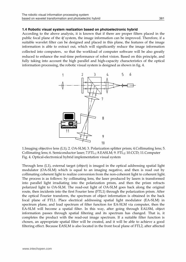
1.4 Robotic visual system realization based on photoelectronic hybrid According to the above analysis, it is known that if there are proper filters placed in the public focal plane of the 4f system, the image information can be improved. Therefore, if a suitable wavelet filter can be designed and placed in this plane, the features of the image information is able to extract out, which will significantly reduce the image information collected into computers,so that the workload of computer software will be also greatly reduced to enhance the real-time performance of robot vision. Based on this principle, and fully taking into account the high parallel and high-capacity characteristics of the optical information processing, the robotic visual system is designed as shown in fig. 4.
1.Imaging objective lens (L1); 2. OA-SLM; 3. Polarization splitter prism; 4.Collimating lens; 5. Collimating lens; 6. Semiconductor laser; 7.FTL1; 8.EASLM; 9. FTL2; 10.CCD; 11.Computer Fig. 4. Optical-electronical hybrid implementation visual system Through lens (L1), external target (object) is imaged in the optical addressing spatial light modulator (OA-SLM) which is equal to an imaging negative, and then is read out by collimating coherent light to realize conversion from the non-coherent light to coherent light. The process is as follows: by collimating lens, the laser produced by lasers is transformed into parallel light irradiating into the polarization prism, and then the prism refracts polarized light to OA-SLM. The read-out light of OA-SLM goes back along the original route, then incidents into the first Fourier lens (FTL1) through the polarization prism. After the optical Fourier transform, the spectrum of object information is obtained in the back focal plane of FTL1. Place electrical addressing spatial light modulator (EA-SLM) in spectrum plane, and load spectrum of filter function for EA-SLM via computer, then the EA-SLM will become a spatial filter. In this way, after going through EALSM, object information passes through spatial filtering and its spectrum has changed. That is, it completes the product with the read-out image spectrum. If a suitable filter function is chosen, an appropriate spatial filter will be created, and it will be able to achieve a good filtering effect. Because EASLM is also located in the front focal plane of FTL2, after affected
www.intechopen.com

Robot Vision382
by the second Fourier lens (FTL2), object information completes the inverse Fourier transform and transits back to the spatial domain from the frequency domain. In this way, the image information collected by CCD is the information passing through spatial filtering, namely the information extracted object features, so its amount will greatly reduced. Then, input this simplified information into computer system. The workload of computer software is also greatly decreased, and its runtime is shorten greatly, so its real-time performance is enhanced greatly. Known from the above analysis, the innovation of this proposed visual system is to do spatial filtering for object information by adopting filters, and then to extract object features so as to reduce the workload of computer software, as optical information processing speed is the speed of light, so that it can enhance the real-time performance of vision.
1.5 The optical devices of the photoelectric hybrid-based robotic visual system The designed photoelectric hybrid-based robotic visual system is composed of object reader, 4f optical system and computer coding electrical addressing spatial light modulator. The devices mainly include coherent light collimator, optical addressing spatial light modulator, polarization splitter prism,Fourier transform lenses, electrical addressing spatial light modulator, and so on.
1.5.1 The object reading device As shown in fig.5, the main parts of the object reading device consist of spatial light modulator, polarization splitter prism,coherent light collimator, illuminant of writing light, illuminant of reading light, and so on.
Fig. 5. Object reading principle of visual system Under the irradiation of writing light (white light), the object images in OA-SLM. As reading light, collimating coherent light is reflected after irradiating in OA-SLM. In this way, the object information is coupled to the reflected beam, that is, the reflected beam has carried the object information. Then, the reflected light is reflected by polarization splitter prism to read the object image.
www.intechopen.com

The robotic visual information processing system based on wavelet transformation and photoelectric hybrid 383
2. The design of coherent light collimator
Taking into account that the visual system should reliable and durable and its structure should compact, DL230382033 type low current, heat-resistant semiconductor laser is selected as illuminant of writing light. Its wavelength λ is 635 nm, output power is 10mW,
and the working environment temperature is range from C10 to C50 . As the semiconductor laser beam is astigmatic elliptical Gaussian beam, after going through extender lens, the low-frequency part of this Gaussian beam is located in the vicinity of optical axis, while the high-frequency component is far away from the optical axis. To this end, an aperture diaphragm is placed in the back focal plane of the extender lens L1 (as shown in fig. 6), in order to filter out high-frequency component and high-frequency interference noise, so as to improve the quality of coherent light beam.
Fig. 6. Generation of collimated light beam There is an average divergence angle for laser beams due to the width of the waist of Gaussian beam. Considering the influence of divergence angle to the area of focused spot, an aperture diaphragm with d = 15μm is selected by calculating. As shown in fig. 6, the proportion relation between the corresponding edges of the similar triangles is:
2121 DLDLff Where, 1f and 2f respectively denote the focal lengths of extender lens and collimating lens; DL1 and DL2 respectively represent the light-passing diameters of extender lens and collimating lens. Hence, it can be computed that the focal length of collimating lens 2f is 190 mm, and the diameter of collimating light spot is 32mm. The two in fig. 8 respectively represent experimental results of the beams in distance of 500mm and 1000mm from the collimator. The collimation degree of collimator is 0.4%, reaching the desired design effect.
www.intechopen.com

Robot Vision384
Fig. 7. Photo of collimating device
Distance 500l mm Distance 1000l mm Fig. 8. Experiment results of collimated light beam
3. Optical addressing spatial light modulator (OA-SLM)
Optical addressing spatial light modulator (OA-SLM), namely Liquid Crystal Light Valve (LCLV), under the control of illuminant signal, it can modulate light wave, and write the information recorded by source signals into incident coherent light wave. The main performance parameters of LCLV are shown in Table 1. The photo of OA-SLM is shown in Fig. 9.
Size of image plane 4545 2mm gray level 7-8
lowest energy of writing light 6.3 2/ cmW spatial resolution 55 mmLp /
exposure dose of the threshold 3.7 2/ cmErg responding time 30-40ms
lowest energy of reading light 4.0 2/ cmW contrast gradient 150 Table 1. The main performance parameters of LCLV
www.intechopen.com

The robotic visual information processing system based on wavelet transformation and photoelectric hybrid 385
Fig. 9. Photo of O-SLM
4. Real-time reading of object image
By the experiment of object reading device, intensity of writing light, the distance between liquid crystal light valve and polarization splitting prism, as well as working voltage and frequency of liquid crystal light valve all have obvious influence on reading light. Firstly, intensity of reading light and writing light is non-simple corresponding, curves of input and output is campaniform. In upward section, with increase of writing light intensity, reading light intensity monotonously increased, and the output of liquid crystal light valve was positive image, as shown in fig. 10(a). In descent segment, with increase of writing light,reading light intensity monotonously decreased, and the output of liquid crystal light valve was inverse image, as shown in fig. 10(b).
(a) Positive image (b) Inverse image Fig. 10. Experiment results of reading light Secondly, orthogonal experiment between working voltage and working frequency was done, and the results showed that when working frequency was about 3.3 kHz, the output was best, working frequency influence scope was 2.7kHz≤f≤3.5 kHz. In certain working frequency, when voltage was 3.2v or 5.2v, clear object information can be obtained. Compared to original image, the reading object information had some noise, but the obtained image was clear.
www.intechopen.com

Robot Vision386
4.1 Fourier Transform Lenses of optical system The design characteristics of Fourier Transform Lens of 4f system is:its requirements are that every point of front focal plane give off light through lens focus a point of rear focal plane accurately, a point of front focal plane give off light through lens is mutual parallel, and two conjugate surfaces must have sinusoidal conditions. Fourier transform lenses are used in the conditions of homochromatism. If one lens is needed to adapt to several wavelength light, the method is to increase color difference of axial direction, and different wavelength use different focal plane. In addition, focal length of Fourier transform Lens is longer, if focal length is large enough, it can scatter all levels spectrum, and introduce reference light easily. Meanwhile, numbers of lenses should decrease as less as possible to reduce coherent light noise. As Focal length of Fourier transform Lens is longer, to shorten structure size of system, symmetry distance-based Fourier transform Lens structure is adopted.
5. The optical parameters determination of Fourier lens
Double long-distance Fourier transform lens can shorten the distance between pre- focus and post-focus so as to reduce the structure size of the optical processing system. In addition, because variables of this Fourier lens to eliminate aberration are more, it is benefit to enlarge pore sizes and field of view. Because Fourier transform lens computes the complex amplitude of object function, in order to ensure sufficient computing precision, its aberration is need to be strictly corrected. The wave aberration is usually controlled within the diffraction limit, namely ( 41 to 101 ) λ. Therefore, as long as system variables are enough, adopting Fourier transform lens with symmetry structures is beneficial. Thus, in order to adapt to the photoelectric hybrid-based robotic visual system, the double long-distance structure is selected. The main optical parameters of Fourier transform lens are focal length f, the object plane, the working size of spectrum plane, and so on. According to the requirements of 4f coherent processing system, the specific conditions of actual devices are as follows: coherent working wavelength is nm635 , and the maximum diameter of lighting parallel beam is about mm25 which is determined by the light-passing diameter of polarization splitter prism,
and limits the object plane size as a window function ),( yxW . In the spectrum plane, a computer-controlled Thin Film Transistor Liquid Crystal Displays (TFT-LCD) is adopted as a spatial filter, so the size of TFT-LCD determines the size of the spectrum plane. In the object plane, OA-SLM is used as an input device, and its spatial resolution limits the highest spatial frequency of object function image. According to the formula 11 , fvfu ,
when the highest spatial frequency m (or m ) of the object and the maximum size
mu2 (or mv2 ) of spectrum plane are known, the focal length of the Fourier transform lens FTL1 can be determined:
m
muf 1
or m
mvf 1 (9)
www.intechopen.com

The robotic visual information processing system based on wavelet transformation and photoelectric hybrid 387
Similarly, for FTL2, its spectrum plane size is same as that of FTL1, and its image plane size is determined by the receiver (CCD), so the focal length of the Fourier transform lens FTL2 should meet the following relationship:
112 fWWff
(10) Where
WW
ff 1
2 —linear magnification of 4f imaging system.
In photoelectric hybrid-based robotic visual system, the main working parameters of the selected devices are as follows: 1. Optical Addressing Spatial Light Modulator (OA-SLM) Its spatial frequency is mmlp /40max1 , and the light-passing diameter is mm40 . 2. Thin Film Transistor Liquid Crystal Displays (TFT-LCD) SVGA1 produced in British CRL company is introduced, and its spatial frequency is
mmlp /30max2 ; the size of Liquid Crystal Display is
)(16.20)(48.28 HmmWmm .
3. CCD: its camera element is 21 inch, and the resolution is 600 lines.
4. Polarization splitter prism: the working area is mm25 . Based on these data, optical parameters of FTL1 and FTL2 are as shown in Table 2.
Fourier Transform Lens focal length image (object)
plane size spectrum plane size
FTL1 381mm 25mm 25mm FTL2 252mm 25mm 25mm
Table 2. Optical parameters of FTL1 and FTL2 Affected by pixel size of EA-SLM of loading spatial filter and array structure, a number of images will overlapped in the output plane of the processing system. In order to separate these images, the input object plane size should be reduced to meet the following relationship:
1fW Fe (11) Where, eW —Limited working size of the object plane;
F —Spatial resolution of filter. According to formula (10) and (11), limited sizes of object plane and image plane can be obtained, and they respectively are mmWL 25.7 , mmWL 7.9 . However, in order to make optical elements have good generality, they are still designed in accordance with Table 2.
www.intechopen.com

Robot Vision388
6. Comprehensive evaluation of optical design result and image quality of Fourier lenses
According to the demand of design, the structures of the designed Fourier transform lenses and optical parameters are shown as fig. 11, fig. 12, table 3 and table 4 respectively. Their geometric aberration, wave aberration and optical modulation transfer function curves are shown as fig. 13, 14, 15 and 16. Two Fourier transform lenses are shown as fig. 17 and fig. 18.
Fig. 11. Optical system of FTL1 (Unit: mm)
focal length f 381.01 relative aperture D/f 1/15.24 object distance LF -140.05 object plane, spectrum
plane diameter D 25
spectral plane distance L’F
140.05 coherent wavelength λ
635nm
cylinder length L 180.25 maximum wave aberration W
0.088λ
distance between two focus D
460.35 disposable highest spatial frequency v
51.6lp/mm
Table 3. Main optical parameters of FTL1 system (Unit: mm)
Fig. 12. Optical system of FTL2 (Unit: mm)
www.intechopen.com

The robotic visual information processing system based on wavelet transformation and photoelectric hybrid 389
focal length f 252.01 relative aperture D/f 1/10.1 object distance LF -32.48 object plane, spectrum
plane diameter D 25
spectral plane distance L’F
32.48 coherent wavelength λ
635nm
cylinder length L 153.69 maximum wave aberration W
0.1λ
distance of two focus D
218.65 disposable highest spatial frequency v
78.1p/mm
Table 4. Main optical parameters of FTL2 system (Unit: mm)
Fig. 13. Spherical aberration of FTl
Fig. 14. Astigmatism and distortion of FTL
www.intechopen.com

Robot Vision390
Fig. 15. Modulated transfer function of FTL
Fig. 16. Optical path difference of FTL Known from the above, transfer function of both Fourier transform lenses are completely same as diffraction-limited transfer function, and the wave aberration is controlled within the wavelength of 101 in the whole field range. This shows that both Fourier transform lenses are excellent, and the design is successful.
www.intechopen.com

The robotic visual information processing system based on wavelet transformation and photoelectric hybrid 391
Fig. 17. Photo of Fourier transform lens
Fig. 18. Photo of Fourier inverse transform lens 6.1 Loading and experiment of wavelet filter Adding wavelet filter in spectrum plane can change spectrum to process image. So, SVGA1 electrical addressing spatial light modulator produced in British CRL Company is introduced as loading platform of wavelet filter. The wavelet filter is added to electrical addressing spatial light modulator through computer programming method to realize photoelectric hybrid system of image information.
7. Electrical Addressing Spatial Light Modulator (EA-SLM)
The input signal of electrical addressing spatial light modulator, type SVGA1, is electrical, the electrical signal is time series, and transported into the pixels of spatial light modulator (SLM) successively with serial addressing mode. The modulator is mainly composed of a driver card and a Liquid Crystal Device (LCD), the card is supported by 12V power supply and connected to PC by parallel interface, the LCD connects to drive card through a special flat cable with a 30 pins plug, and its spatial resolution is , mmLp /30max .
www.intechopen.com

Robot Vision392
On the inner face of the two substrates of LCD, there are orthogonal grating transparent poles printed by Photo lithography. The liquid crystal layer is packaged between the substrates. The horizontal grids printed on the front surface are scanning poles, and the vertical grids printed on the back surface are signal poles. If neglecting the lag of liquid crystal responding to external electrical field, for the pixel at the crossing point of scanning pole and signal pole,the transmittance of pixel is depended on the voltage between the two poles. Thus, the scanning pole and signal pole divide the LCD into pixel elements of matrix form that is Thin Film Transistors (TFT) array. These TFT and electrical pole arrays can be observed by microscope in strong light. The material of liquid crystal is light-electrical, and responds to voltage applied. The pixel transmittance, namely pixel gray, is controlled by voltage of scanning pole and signal pole. The pixel array of type SVGA1 light modulator is showed in fig. 19(a). There are 800 pixels in the width direction, 600 pixels in the height direction, and the length of span is 33 m . Every pixel is a controllable unit with 24μm(Height)× 26μm(Width). LCD is very different from analog display unit, such as pixel and signal having no single valued relation. Although signals received by electrical addressing spatial light modulator is analog, the transmittance responding to voltage is non-linear, as fig. 19(b),and this nonlinear can be compensated by countermeasour.
Fig. 19. Pixel orientati on and voltage res ponse curve of LCD
8. Optical wavelet filter
There are various kinds of wavelet function, including Morlet wavelet, Haar wavelet, Mexican-hat wavelet, Spline wavelet and Daubechies wavelet. In practical engineering, Haar wavelet and Mexican-hat wavelet have got widely used. Here, using computer programming, optical wavelet filter is constructed in electrical addressing spatial light modulator.
www.intechopen.com

The robotic visual information processing system based on wavelet transformation and photoelectric hybrid 393
1. Optical Haar wavelet filter One-dimensional Haar wavelet is a bipolar step-type function, and there are three forms of the two-dimensional combination, including horizontal edge wavelet, vertical edge wavelet and angular Haar wavelet. The important characteristic of Haar wavelet is its orthogonal nature. So it is commonly used in corner feature extraction of binary image function. Two-dimensional Haar wavelet function can be expressed as:
)5.0,5.0()5.0,5.0(),( yxrectyxrectyx It is staggeredly consisted of two pairs of bipolar two-dimensional rectangular function. Obviously, Haar wavelet function is not continuous, and its combinations in different forms have good effects when extracting the corner features of images. When optical Haar wavelet filter is constructed based on computer programming method, the Haar wavelet function should be sampled at first; and then sample points are Fourier transformed; finally, Haar wavelet function spectrum is obtained. As long as the sample points are enough, the needed optical Haar wavelet filter 1 will be designed. Fig. 20 is the Haar wavelet spectrum when sample point numbers are 100. Seen from Fig. 20, Haar wavelet spectrum obtained by computer programming is more normative than that of physical methods, and flexible to operate.
Fig. 20. Frequency spectrum of Haar wavelet when sample points are 100 Dual-cross optical Haar wavelet filter can be constructed by further graying the spectrogram of Haar wavelet function. 2. Optical Mexican-hat wavelet filter The forms of two-dimensional Mexican-hat wavelet in spatial domain and frequency domain respectively are:
)
2exp()](1[),(
2222 yxyxyxh
(12)
www.intechopen.com

Robot Vision394
)](2exp[)(4),( 22222222 vuvuvuH (13) Equation (12) and (13) are both real-even functions, and their morphologies are shown as Fig. 21 (a). In optical system, Mexican-hat wavelet is often approximated as ring-band filters in frequency domain, which constitutes the wavelet filter as shown in Fig. 21 (b).
Fig. 21. Morphologies of Mexican-hat wavelet and the wavelet filter
8.1 The noise processing of optical addressing spatial light modulator (OA-SLM) In the designed system, incoherent images are transformed into coherent images by Optical Addressing Spatial Light Modulator (OA-SLM) in the speed of light; however, the resolution of OA-SLM can not be comparable with the wavelength of light, so it inevitably introduces pseudo-frequency when segmenting the objective images in special domain, and then there is Quantization Noise generated when quantizing the image energy. Therefore, during image processing, to remove interference noise is an important issue which must be settled. Here, according to the parameters of OA-SLM in the proposed system, prepositive antialiasing filter was designed.
9. Sampling theory
The frequency of light wave is above 1014Hz, but the highest resolution of present OA-SLM is 60lp/mm, which can be considered as that sampling continuous image by spatial light modulator. Sampling processing is for every T seconds sampling the analog signal x (t), and the time t is discretized into the unit of sampling interval T, t = nT, n = 0,1,2,3 ......For this reason, plenty of pseudo high-frequency composition is inevitably introduced in the frequency domain which are regular, that is, each frequency composition is the periodic ( Tf s 1 )reproduction of the original signal in the whole frequency axis. Taking the
sinusoidal signal )2exp()( jfttx of a single frequency f for example, before the
sampling, its frequency is f . But after sampling, it is )2exp()( fnTnTx , that means
copying the original frequency periodically with intervals of sf and it can be expressed as
smfff , ...3,2,1,0 m . As a result, there will be much more confusion added to
www.intechopen.com

The robotic visual information processing system based on wavelet transformation and photoelectric hybrid 395
the original signal, and with the introduction of pseudo-frequency, in order to avoid interference, it must satisfy the sampling theorem. Spatial sampling of spatial light modulator is similar to the above processing. It simples the spatial continuous image ),( yxf . The resolution of OA-SLM is 35lp/mm, so the sampling
frequency 35sf kHz, and then deduced from max2 ff s , the maximum frequency is
5.17max f kHz, namely the spatial frequency to process images is up to 17.5kHz.
10. Design of antialiasing pre-filters
For sampling signal under the ideal condition and meeting sampling theory, the signal must be filtered by antialiasing pre-filters, cut-off frequency maxf of pre-filters is at least 2sf , spectrum replication induced by sampling process is shown as fig. 22.
Fig. 22. Antialiasing pre-filters Analyzed based on Fourier transform, the output of sampler is considered composing by pulses of sampling points, and its weight is the corresponding sampling value, so, sampling signal is:
nnTtnTxtx )()()(ˆ
(14) Its spectrum is:
msmffX
TdtjfttxfX )(1)2exp()(ˆ)(ˆ
(15) From the above equations, spectrum replication can be known.
www.intechopen.com

Robot Vision396
Perfect filters are shown as fig. 22, which have got rid of stimulant input signals exceed |2| sf .But in fact, antialiasing pre-filters is not ideal, and it can’t completely filtrate all
frequency which is bigger than |2| sf , so it introduce aliasing necessarily. To solve this problem, it can design rational pre-filters to reach concessional bound in engineering. Actual antialiasing pre-filters are shown as fig. 23, and ],[ passpass ff is important
frequency range, which must be within ],[ passpass ff . In optics system, Fresnel
diffraction (far-field diffraction) can be used for filtrate antialiasing. As locating before spectrum, it also called antialiasing pre-filters.
Fig. 23. The practical antialiasing lowpass pre-filter
Fig. 24. The sketch map of diffraction
This system use laser as lamp-house, so it analyzes diffraction which cast monochrome plane wave to a hatch ∑ as shown in fig. 24. Let hatch plane is xy plane, transforming plane is uv plane, yx、 axis parallels vu、 axis respectively.
www.intechopen.com

The robotic visual information processing system based on wavelet transformation and photoelectric hybrid 397
If coordinates of Q is ),( yx and coordinates of P is ),( vu , distance r between these two points is:
222 )()( yvxuzr (16) If distance between watching plane and hole is bigger than the dimension of the hole, and only considering that field angle is not big field of diffraction hole in the transforming plan (paraxial nearby), 1cos (error is less than %5 when is lower than 18 ). r can be expressed as follows:
2/122 ])()(1[zyv
zxuzr (17)
1)()( 22 zyv
zxu
, via making binomial theorem on radical of above formula, the
following relationship can be obtained:
...}])()[(81)(
21)(
211{ 22222
zyv
zxu
zyv
zxuz
r
(18) Omiting over quadratic term, then it can get:
])(21)(
211[ 22
zyv
zxuzr (19)
Substituting (19) to )exp(ikr , it can get:
])()[2
22
)exp(yvxu
zik
ikr eeikr (20)
Therefore, from the Kirchhoff diffraction formula:
dikrQEri
pE )exp()(~2cos11)(~
(21)
The following relationship can be obtained:
dxdyyvxuzikyxE
zievuEikz ]})()[(
2exp{),(~),(~ 22
(22)
Where, the integral interval is aperture Σ, when beyond Σ, the complex amplitude
0),(~ yxE .
www.intechopen.com

Robot Vision398
Fig. 25. The transform effect of lens In the optical wavelet transform system, as fig. 25, the input plane xy locates in d1 where
is front of the lens L, and output planar uv locates in 2d where is behind of lens L.
Suppose the transmission of light wave between 1d and 2d meets the Fresnel
approximation condition, then the lens’ anterior surface field ),( yxl can be expressed as:
dxdyyxdkiyx
dieyx o
ikd
l ]})()[(2
exp{),(),( 22
11
1
(23)
Phase transform effect of lens is as follows:
),()](2
exp[1),( 22' yxfkie
ft l
ikflll
(24)
Where, the constant phase term )exp( ik is omitted. Using the Fresnel approximation formula again, the field of output planar ),( vu can be got:
ddvudki
dievu l
ikd
]})()[(2
exp{),(),( 22
2
'
2
2
(25)
Substituting equation (23) and (24) into (25), the following relationship can be got:
dxdyyxyxdkiyxee
fddvu o
vudki
fddik ),()](2
exp[),(1),( 22
1
)](2
[)(
212
22
221 (26)
where:
dddv
dy
du
dx
fddkiyx ]})(2)(2))(111[(2
exp{),(2121
22
21
www.intechopen.com

The robotic visual information processing system based on wavelet transformation and photoelectric hybrid 399
Define fdd 21 , then:
dxdyyvxuf
ivufievu o
ikf
)](2exp[),(),( 2
(27)
Then, restrict Σ as rectangular opening with the length and width b and a separately. Define the origin coordinates at the center of the rectangular opening, and
supposeful ,
fvm , let ),(
2vu
fieC o
ikf , so (27) can be transformed as:
2
2sin
2
2sin
)(exp(),( 2
2
kla
kla
klb
klb
abC
dxdymylxikCvub
b
(28)
Let 2klb ,
2kla ,then light intensity of point P is:
220 )sin()sin(
II
(29)
Where, 0I is light intensity of point 0P on the optical axis. Then, analyze the distribution of light intensity in one-dimensional space, and take y axis for
example, then 20 )sin(
II . Obviously, when 0 , 0II , so the 0P point has the
maximum intensity, and when ...3,2, , 0I , the points corresponding to the values are dark.
Fig. 26. The optical intension diffraction
www.intechopen.com

Robot Vision400
Between the two minimum values of intensity, there is a second maximum value. These positions of maximum values can be obtained from following formula:
0)sin( 2
dd
, that is tg (30)
From fig. 26, it can be seen that suitable a and b can make the maximum intensity as prepositive removing aliasing filter. According the above analysis, a and b are both equal to mm14 .
10.1 Experiment result On the optical experimental platform, the experimental devices of the visual system based on wavelet transformation and photoelectric hybrid is constructed, as shown in fig. 27. In order to verify the correctness of system scheme, it adopted different types and factors optical wavelet function filter in the experiment, and operated graphic feature extraction experiment for corresponding target. Fig. 28 shows the graphic edge feature extracted form targets typing L using Mexican-hat wavelet filter.
Fig. 27. Photo of experiment system
www.intechopen.com

The robotic visual information processing system based on wavelet transformation and photoelectric hybrid 401
Fig. 28. Results of L-shape objective image feature extracting
11. References
1. J. Z. Sasiadek. Sensor fusion. Annual Reviews in Control. 2002, 26(2): 203-228 2. Nic Fleming. Interview: Robotic futures. The New Scientist. 2009, 203: 28-29 3. Amir A.F. Nassiraei, Kazuo Ishii. Concept of Intelligent Mechanical Design for
Autonomous Mobile Robots. Journal of Bionic Engineering, Volume 4, Issue 4, December 2007, Pages 217-226
4. H.R.Nicholls,M.H.Lee. A Survey of Robot Tactile Sensing Technology. The Int. J, of Robotics Research. 1989, 8(3): 3-30
5. CAI Zixing. Advances in intelligent robots: Trends and gaming. Robot. 1996,8(4): 248-252
6. Nguyen, Minh-Chinh. Vision-based Intelligent Robots. Proceeding of SPIE-The International Society for Optical Engineering. 2000, 4080: 41-47
7. Waurzyniak, Patrick. Robot Vision Guides Assembly. Manufacturing Engineering. 1999, 123(3): 42-46
8. Rhee Sehun, Lee Chang Hee. Automatic Teaching of Welding Robot for Free-formed Seam Using Laser Vision Sensor. Optics and Lasers in Engineering. 1999, 31(3): 173-182
9. Ferretti, Marc. Vision Sensors Give Eyes to the Welding Robot. Welding Journal. 1999, 78(7): 51-52
10. Meguro Shin-ichi, Muto Shin-yo, Katayama Atsushi. New Arc Welding Robot System Equipped with Laser Vision Sensor and Spatial Path Generation Scheme. NTT R&D. 1998, 47(7): 819-824
11. Uota, Koichi. Servo Robot’s Laser Vision System for Welding. Sumitomo Metals. 1997, 49(3): 73-78
12. Wira P., Kihl H.. Robot Vision Tracking with a Hierarchical CMAC Controller. International Conference on Knowledge-Based Intelligent Electronic Systems. 2000, : 271-274
www.intechopen.com

Robot Vision402
13. Zanela Andrea, Taraglio Sergio. Cellular Neural Network Stereo Vision System for Autonomous Robot Navigation. Proceedings of the IEEE International Workshop on Cellular Neural Networks and Their Applications. 2000, : 117-122.
14. Graf, Birgit. Small Robot Agents with On-board Vision and Local Intelligence. Advanced Robotics. 2000, 14(1):51-64
15. Deguchi, Koichiro. Direct Interpretation of Dynamic Images with Camera and Object Motions for Vision Guided Robot Control. International Journal of Computer Vision. 2000, 37(1): 7-20
16. Bonarini Andrea, Aliverti Paolo, Lucioni Michele. Omnidirectional Vision Sensor for Fast Tracking for Mobile Robots. IEEE Transactions on Instrumentation and Measurement. 2000, 49(3): 509-512
17. Okhotsimsky D.E., Platonov A.K., et al.. Vision System for Automatic Capturing a Moving Object by the Robot Manipulator. IEEE International Conference on Intelligent Robots and Systems. 1998, 2: 1073-1079
18. Abe Yasunori et al. Vision Based Navigation System for Autonomous Mobile Robot. JSME International Journal. Series C: Mechanical System, Machine Elements and Manufacturing. 2000, 43(2): 408-414
19. Murray Don, Little James J. Using Real-time Stereo Vision for Mobile Robot Navigation. Autonomous Robots. 2000, 8(2): 161-171
20. Shim Hyun-Sik, et al.. Design of Action Level in a Hybrid Control Structure for Vision Based Soccer Robot System. IEEE International Conference on Intelligent Robots and Systems. 1999, Oct.: 1406-1411
21. Cannata, Giorgio, et al.. On Perceptual Advantages of Active Robot Vision. Journal of Robotic Systems. 1999, 16(3): 163-183
22. Nygards, Jonas, Wernersson, Ake. On Covariances for Fusing Laser Rangers and Vision with Sensors Onboard a Moving Robot IEEE International Conference on Intelligent Robots and Systems. 1998, Oct.: 1053-1059
23. Nakamura, T., et al.. Development of a Cheap On-board Vision Mobile Robot for Robotic Soccer Research. IEEE International Conference on Intelligent Robots and Systems. 1998, Oct.: 431-436
24. Aufrere R. A Dynamic Vision Algorithm to Locate a Vehical on a Nonstructured Road. The International Journal of Robotics Research. 2000, 19(5):411-423
25. Vilesoma SW, Rolfe D F H, Richards R J, Eye-to-hand ,Coordination for Vision-guided Robot Control Applications. The Int. J of Robotics Research, 1993, 12(1): 65-78
26. Hen W Z, Korde U A, Skaar S B, Position Control Exteriments Using Vision. The Int. J. of Robotics Research, 1994, 13(3): 199-208
www.intechopen.com

Robot VisionEdited by Ales Ude
ISBN 978-953-307-077-3Hard cover, 614 pagesPublisher InTechPublished online 01, March, 2010Published in print edition March, 2010
InTech EuropeUniversity Campus STeP Ri Slavka Krautzeka 83/A 51000 Rijeka, Croatia Phone: +385 (51) 770 447 Fax: +385 (51) 686 166www.intechopen.com
InTech ChinaUnit 405, Office Block, Hotel Equatorial Shanghai No.65, Yan An Road (West), Shanghai, 200040, China
Phone: +86-21-62489820 Fax: +86-21-62489821
The purpose of robot vision is to enable robots to perceive the external world in order to perform a large rangeof tasks such as navigation, visual servoing for object tracking and manipulation, object recognition andcategorization, surveillance, and higher-level decision-making. Among different perceptual modalities, vision isarguably the most important one. It is therefore an essential building block of a cognitive robot. This bookpresents a snapshot of the wide variety of work in robot vision that is currently going on in different parts of theworld.
How to referenceIn order to correctly reference this scholarly work, feel free to copy and paste the following:
Dai Shi-jie and Huang-He (2010). The Robotic Visual Information Processing System Based on WaveletTransformation and Photoelectric Hybrid, Robot Vision, Ales Ude (Ed.), ISBN: 978-953-307-077-3, InTech,Available from: http://www.intechopen.com/books/robot-vision/the-robotic-visual-information-processing-system-based-on-wavelet-transformation-and-photoelectric-h

© 2010 The Author(s). Licensee IntechOpen. This chapter is distributedunder the terms of the Creative Commons Attribution-NonCommercial-ShareAlike-3.0 License, which permits use, distribution and reproduction fornon-commercial purposes, provided the original is properly cited andderivative works building on this content are distributed under the samelicense.


![[CB16] BLE authentication design challenges on smartphone controlled IoT devices: analyzing Gogoro Smart Scooter by Chen-yu Dai [GD] & Professor Shi-Cho Cha [CSC]](https://static.fdocuments.in/doc/165x107/587756e61a28ab84388b77d9/cb16-ble-authentication-design-challenges-on-smartphone-controlled-iot-devices.jpg)