DAGR INTRODUCTION. DAGR Purpose DAGR –Is a Handheld or Host Platform mounted unit –Navigate...
49
DAGR INTRODUCTION
-
Upload
sabrina-dana-hoover -
Category
Documents
-
view
255 -
download
10
Transcript of DAGR INTRODUCTION. DAGR Purpose DAGR –Is a Handheld or Host Platform mounted unit –Navigate...

DAGRINTRODUCTION
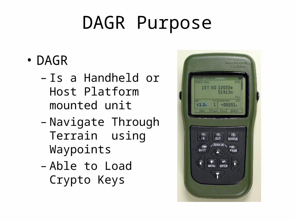
DAGR Purpose
• DAGR– Is a Handheld or Host
Platform mounted unit– Navigate Through Terrain
using Waypoints– Able to Load Crypto Keys

Characteristics
• Provides Position, Velocity, and Time (PVT)
• Includes battery pack and internal antenna with options for external primary power and antenna

Capabilities and Features
• Signal acquisition using up to 12 channels
• All satellites in view are tracked using 11 channels
• Navigation using up to 10 channels
• L1: Course/Acquisition (C/A), Precise (P), and Encrypted P (Y) code capability
• L2: Precise (P), and Encrypted P (Y) code capability
• Accepts differential GPS signals
• One handed operation

Capabilities and Features
• Backlit display and keypad for night operation
• Operates in all weather, day or night• Produces no signals that can reveal your
position• Automatically tests itself during power up• Can operate on +9 to +32 volts direct
current (V DC) external power• Can perform area navigation functions,
storing up to 999 waypoints• Stores up to 15 routes with up to 1000 legs
for each route

Capabilities and Features
• Resists jamming• Resists spoofing when crypto keys are installed• Sealed against dust and water to a depth of 1
meter (3 feet) for 20 minutes• Interconnects with other electronic systems• Uses quick disconnect connectors and fasteners
to allow easy unit replacement• Compatible with night vision goggles (NVG)
and does not cause blooming• Uses internal compass to compute track and
ground speed when moving at or below 0.5 meters per second.

CHECK ON LEARNING
• What does PVT stand for?– Position, Velocity, Time
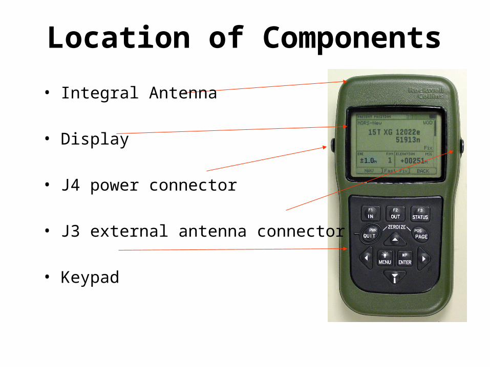
Location of Components
• Integral Antenna
• Display
• J4 power connector
• J3 external antenna connector
• Keypad

Location of Components
• J1 Serial Data I/O Port
• J2 Serial Data I/O Port
• Memory Battery Pack
• Primary Battery Pack
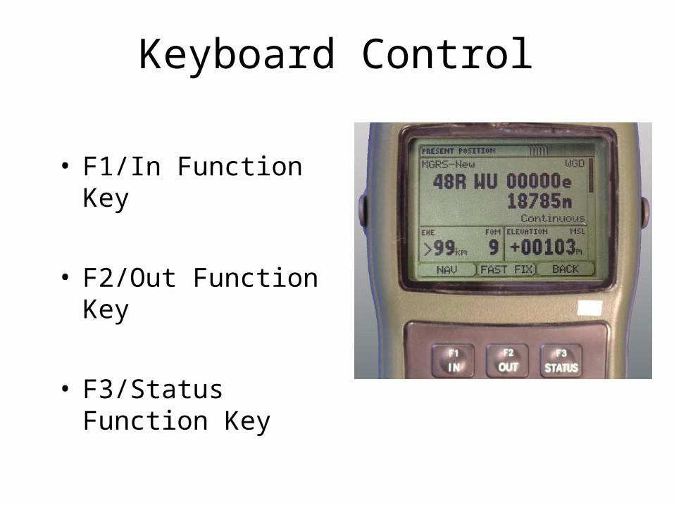
• F1/In Function Key
• F2/Out Function Key
• F3/Status Function Key
Keyboard Control

• PWR/Quit Key
• POS/page Key
• Brightness/Menu Key
• WP/Enter Function Key
• Cursor Control Keys
Keyboard Control

Multifunction Keys
• PWR/Quite Key and POS/Page Key
• Brightness/Menu Key and Up or Down Cursor Control key

Display Indicators
• Lighting Status Indicator
• Primary Battery Status Indicator
• Function Key Labels

Display Windows
• DAGR display contains three
windows
• Only Fields in windows may be selected

• Page Window– Majority of Display
Interaction
– May contain read only data or can be modified data
– May contain multiple horizontal or vertical views
Display Windows

• Tool Bar Window– Three Display Regions
– Display Labels for function Keys
Display Windows

Display Windows
• Message Window– Operator Notification
– Categorized as• Notes
• Alerts
• Cautions
• Warnings

• Pop-up Window– Displayed over Page
Window
– Have Menus
– Allows Editing
– Help Text
Display Windows

DAGR Editors
• List Editors
• Text Editors
• Number Editors

DAGR Editors
• Number Editors

DAGR Editors
• List Editors

DAGR Editors
• Text Editors

DAGR Menus
• DAGR Menus– Main Menu– Submenu– Page Menu– Field Menu

DAGR Menus
• Main Menu Access– Top Level Menu– Push the MENU Key Twice to
Access– Use the QUIT key access from
Submenu– Use Menu Key to access from
Page Menu– Use Menu Key to access from
Field Menu
DAGR Menus
• Submenu Access– Accessed from Main Menu– Cursor control Keys to view
entire Submenu

DAGR Menus
• Page Menu Access– Associated with Submenu
• Note– Other Pages of Submenu
accessed with PAGE and QUIT Key

DAGR Menus
• Field Menu Access– Associated with Highlighted
Fields

CHECK ON LEARNING
• How many sets of Multifunction keys does the DAGR have?– Two sets
• What is the text editor used for?– To edit text & numeric characters
• What are the four Menu types?Main, Sub, Page, & Field

DAGR OPERATIONAL CHECKOUT
Do the following before using the DAGR:
• Ensure the correct function set is being used • Ensure the correct user profile is being used if using the advanced function set.
•Set the DAGR to the desired operating mode.

DAGR OPERATIONAL CHECKOUT
Operational Checkout1. Inspect the DAGR [and external cables and
equipment] for damage and/or missing parts. (Refer to the parts list for associated parts used.)
2. b. Push the POWER key to turn the DAGR on and make sure the DAGR has a clear view of the sky.
3. c. During power up, observe the power-on status display. Make sure that self-test passes and battery indication shows sufficient battery power left. Do not use the DAGR if a failed self-test is indicated.

DAGR OPERATIONAL CHECKOUT
After the DAGR successfully completes power-on self-test and shows the SV Sky View page or Present Position page, perform the following procedure for an operator induced commanded self-test.
DAGR OPERATIONAL CHECKOUT
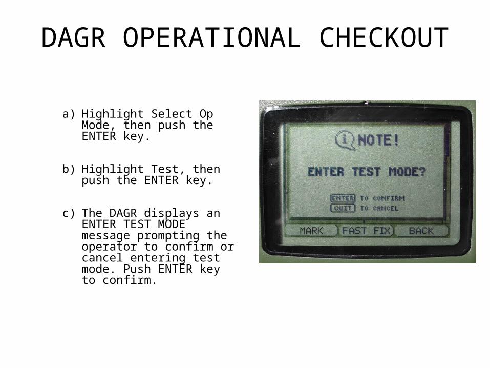
a) Highlight Select Op Mode, then push the ENTER key.
b) Highlight Test, then push the ENTER key.
c) The DAGR displays an ENTER TEST MODE message prompting the operator to confirm or cancel entering test mode. Push ENTER key to confirm.
DAGR OPERATIONAL CHECKOUT
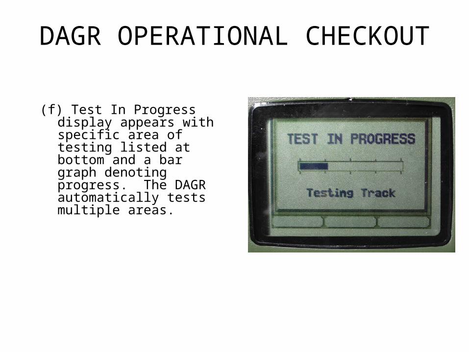
(f) Test In Progress display appears with specific area of testing listed at bottom and a bar graph denoting progress. The DAGR automatically tests multiple areas.
DAGR OPERATIONAL CHECKOUT
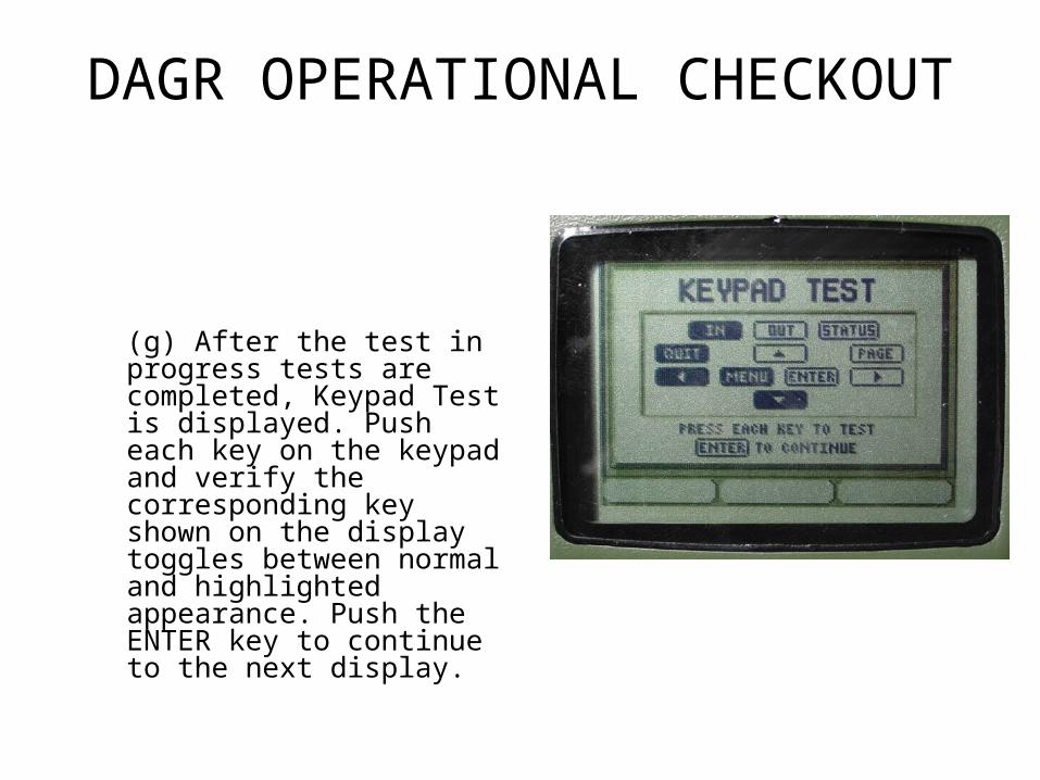
(g) After the test in progress tests are completed, Keypad Test is displayed. Push each key on the keypad and verify the corresponding key shown on the display toggles between normal and highlighted appearance. Push the ENTER key to continue to the next display.

DAGR OPERATIONAL CHECKOUT
(h) Display Light Test display appears with the brightness adjustment cycling between 0% and 100%. The percentage adjustment is reflected in the light bulb of the display. Verify the display lighting by viewing the DAGR display in a dark area. Push ENTER key to continue.

DAGR OPERATIONAL CHECKOUT
(i) Contrast Test display appears with the contrast adjustment cycling between 0% and 100%. The percentage adjustment is reflected in the bar graph of the display. Push ENTER key to continue.

DAGR OPERATIONAL CHECKOUT
(j) The Display Test Beginning message appears momentarily. After sequencing through white, light gray, dark gray, and black, the Display Test Completed message appears, followed by the Power-On Status display listing self-test results as Pass or Fail.
DAGR OPERATIONAL CHECKOUT
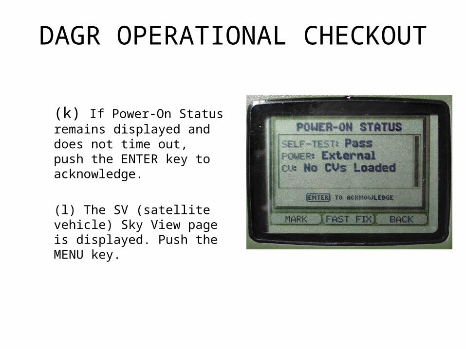
(k) If Power-On Status remains displayed and does not time out, push the ENTER key to acknowledge.
(l) The SV (satellite vehicle) Sky View page is displayed. Push the MENU key.
DAGR OPERATIONAL CHECKOUT
(m) Highlight Select Op Mode, then push the ENTER key.
(n) Highlight Continuous, then push the ENTER key. This mode enables the DAGR to acquire a current position fix.
(o) After satellites are acquired and a current position fix is obtained, the DAGR display stops blinking and Navigate SVs is shown on the SV Sky View page, then automatically switches to the Present Position page.

CHECK ON LEARNING
• What happens if the DAGR does not acquire satellites?– The display blinks between black
and gray text and goes into standby.

DAGR Batteries
• Batteries– Primary Battery and Memory Battery
– Types of Batteries• Lithium AA 1.5 volt; Primary L-91; Battery Life 16.5 hours
• Alkaline AA 1.5 volt; Primary W-B-101; Battery Life 11.5 hours
• Alkaline AA 1.5 volt; Primary 714–4/5; Battery Life 7Hours
• Nickel Metal Hyride AA 1.5 volt; Primary; H-15; Battery Life 10 Hours
• Lithium ½ AA 3.6 volt; Memory LS14500; Battery Life 6 Months
Primary Battery Installation
• WARNING – – Lithium batteries can explode– Reverse polarity can cause damage to
the battery and receiver
• CAUTIONCAUTION – – Battery Types– Do not mix battery type– DAGR Used for Time– DAGR Resets to Default
• Note– No Battery Charge

Primary Battery Installation
a. Ensure power to the DAGR is off.
b. Hold unit firmly upside down with the battery pack facing up.
c. Push or pull latch located on the battery pack to release battery pack. Lift up on battery pack and remove from unit.

Primary Battery Installation
d. Position the battery removal strap into the channel of the battery pack before installing new batteries.
e. Install new batteries and ensure correct polarity installation for each battery (marked on battery pack).

Primary Battery Installation
f. Prior to installing the battery pack, inspect the battery pack gasket for damage or dirt. Lubricate or replace gasket if necessary. Ensure battery removal strap is not protruding from the battery pack.
g. To install new battery pack, position tab on battery pack in slot on the DAGR. Close battery pack against DAGR until battery pack is engaged.

Memory Battery Installation
• Warning– Lithium batteries can explode
– Reverse polarity can cause damage to the battery and receiver
• CautionCaution– DAGR Used for Time
– DAGR Resets to Default
• Note– Battery Types

Memory Battery Installation
a. Ensure power to the DAGR is off.
b. Place unit upside down on non-abrasive surface with the memory battery cover facing up.
c. Use flat blade screw driver to loosen three captive screws securing memory battery cover, then remove cover from unit.
d. Remove the memory battery and properly dispose of battery.

Memory Battery Installation
e. Prior to installing the memory battery cover, inspect the memory battery cover gasket for damage or dirt. Lubricate or replace gasket if necessary.
f. Install the memory battery.
g. Install memory battery cover and tighten three screws.

CHECK ON LEARNING
• What are the two sets of batteries that the DAGR has?– Primary and memory