DABS Modulation and Coding Design - A Summary Modulation and Coding Design – A Summary ... 2.5...
106
FAA-RD-75-93 Project Report ATC-52 DABS Modulation and Coding Design – A Summary T. J. Goblick 12 March 1976 Lincoln Laboratory MASSACHUSETTS INSTITUTE OF TECHNOLOGY LEXINGTON, MASSACHUSETTS Prepared for the Federal Aviation Administration, Washington, D.C. 20591 This document is available to the public through the National Technical Information Service, Springfield, VA 22161
Transcript of DABS Modulation and Coding Design - A Summary Modulation and Coding Design – A Summary ... 2.5...

FAA-RD-75-93
Project ReportATC-52
DABS Modulation and Coding
Design – A Summary
T. J. Goblick
12 March 1976
Lincoln Laboratory MASSACHUSETTS INSTITUTE OF TECHNOLOGY
LEXINGTON, MASSACHUSETTS
Prepared for the Federal Aviation Administration, Washington, D.C. 20591
This document is available to the public through
the National Technical Information Service, Springfield, VA 22161

This document is disseminated under the sponsorship of the Department of Transportation in the interest of information exchange. The United States Government assumes no liability for its contents or use thereof.

*
.
,,,,,,, . Techni’cal ReportDocumentationPag
FormDOTF 17W.7 (8-72) Reprod”ct ion of completedpageautllorlzea

I.
4Section
1.0
2.0
3.0
4.0
CONTENTS
INTRODUCTION
1.1 General1.2 DABS Performance Goals1.3 Summary
UPLINK DESIGN2.1 De sign Options2.2 Electromagnetic Compatibility (EMC) Is sues2.3 Modulation Characteristics2.4 Mes sage Validation2.5 Comparison of “PAM and ~PSK Uplink De:igns2.6 DABS Interrogator Sidelobe Suppression System (ISLS)2.7 Target Acquisition
DOWNLINK DESIGN3.1 Design Constraints and Options3.2 Modulation De sign3.3 Message Decoding3,4 Preamble Design3.5 Downlink Performance Estimates
SUMMARY AND CONCLUSIONS
ACKNOWLEDGMENTS
REFERENCES
Fig.
2-1
2-2(a)
2-2(b)
2-3
2-4
2-5(a)
2-5(b)
2-5(c)
2-6
ILLUSTRATIONS
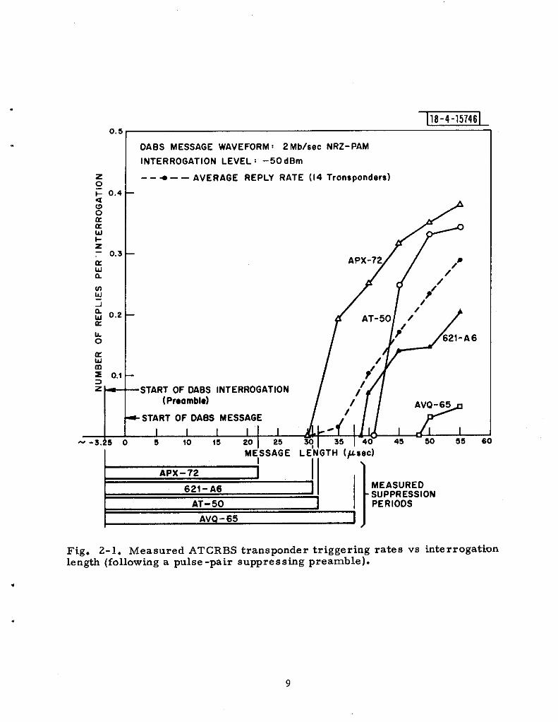
Measured ATCRBS transponder triggering rates vs interroga-tion length (following a p~lse -pair ~~ppre ssing preamble)
ATCRBS transponder suppression in side and back lobes ofDABS sensor
ATCRBS transponder suppression as a function of DABSsensor traffic loading and reliability
Effects of DABS uplink on TACAN/DME beacons
DABS uplink effects on a TACAN interrogator
DPSK demodulator, type 1
DPSK demodulator, type 2 (delay and multiply receiver)
DPSK demodulator filter impulse responses
Probability of bit errors for three binary modulations innoise only (p= O); in pulsed interference (P=o. 2) or (SIR =-14 dB) Vs SNR.
Page
7
112
446
1“224315354
5a5a68757882
95
97
9a
9
10
10
13
14
17
17
17
18
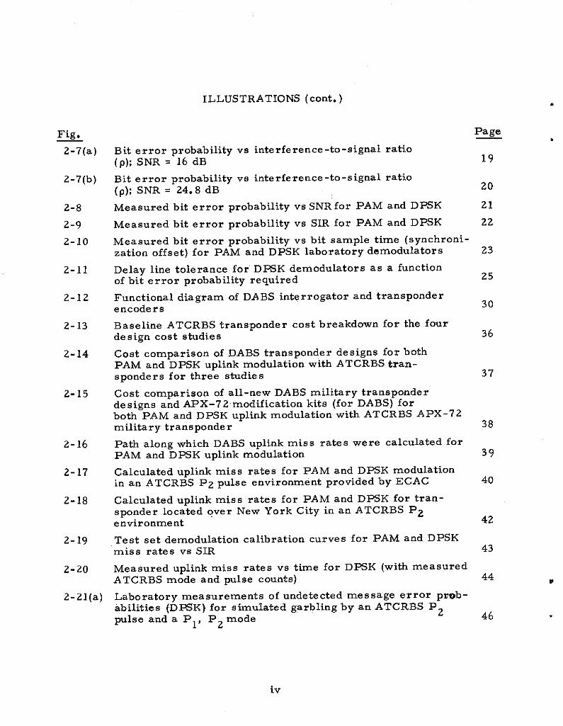
Fig.
2-7(a)
2-7(b)
2-8
2-9
2-10
2-11
2-12
2-13
2-14
2-15
2-16
2-17
2-18
2-19
2-20
2-21(a)
ILLUSTRATIONS (cont. )
Page
Bit error probability vs interference -to-signal ratio(p); SNR = 16 dB 19
Bit error probability vs interference -to -signal ratio(p); SNR = 24.8 dB 20
Measured bit error probability vs SNRfOr PAM and DXK 21
Measured bit error probability vs SIR for PAM and DPSK 22
.
,
Measured bit error probability vs bit sample time (synchroni-zation offset) for PAM and DPSK laboratory demodulators
Delay line tolerance for” DPSK demodulators as a functionof bit error probability required
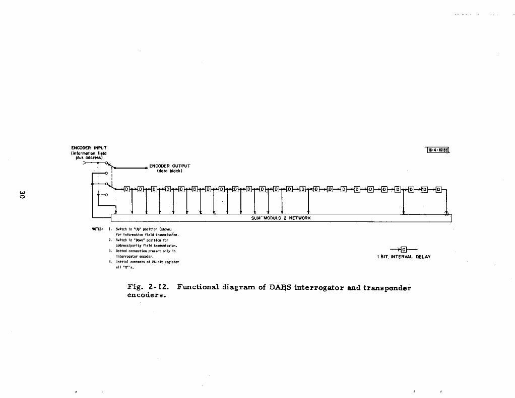
Functional diagram of DABS interrogator and transponderencoders
Baseline ATCRBS transponder cost breakdown for the fourdesign cost studies
Cost comparison of DABS transponder designs for bothPAM and DPSK uplink modulation with ATCRBS tran-sponders for three stidies
Cost comparison of all-new DABS military transponderdesigns and APX-72modification kits (for DABS) forboth PAM and DPSK uplink modulation with ATCRBS APX-72military transponder
Path along which DABS uplink miss rates were calculated forPAM and D~K uplink modulation
Calculated uplink miss rates for PAM and DPSK modulationin an ATCRBS P2 pulse environment provided by ECAC
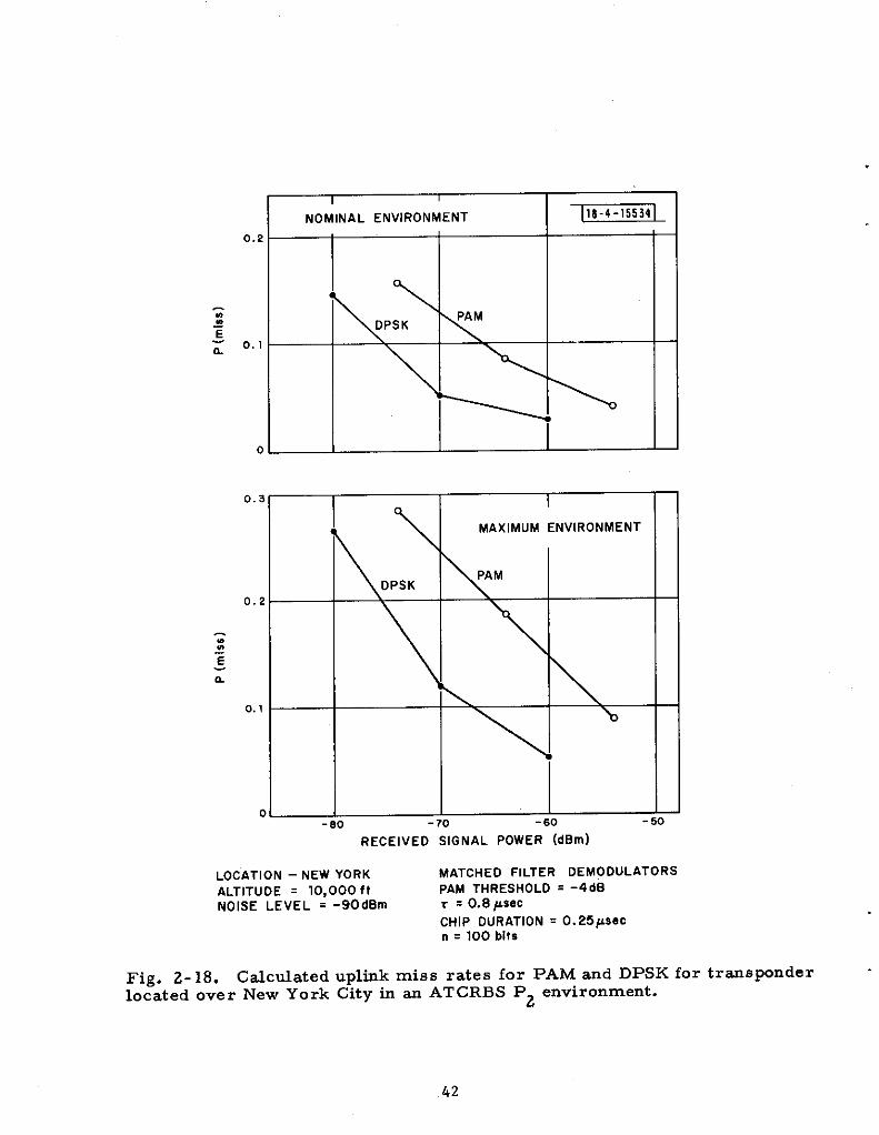
Calculated uplink miss rates for PAM and DPSK for tran-sponder located over New York City in an ATCRBS P2environment
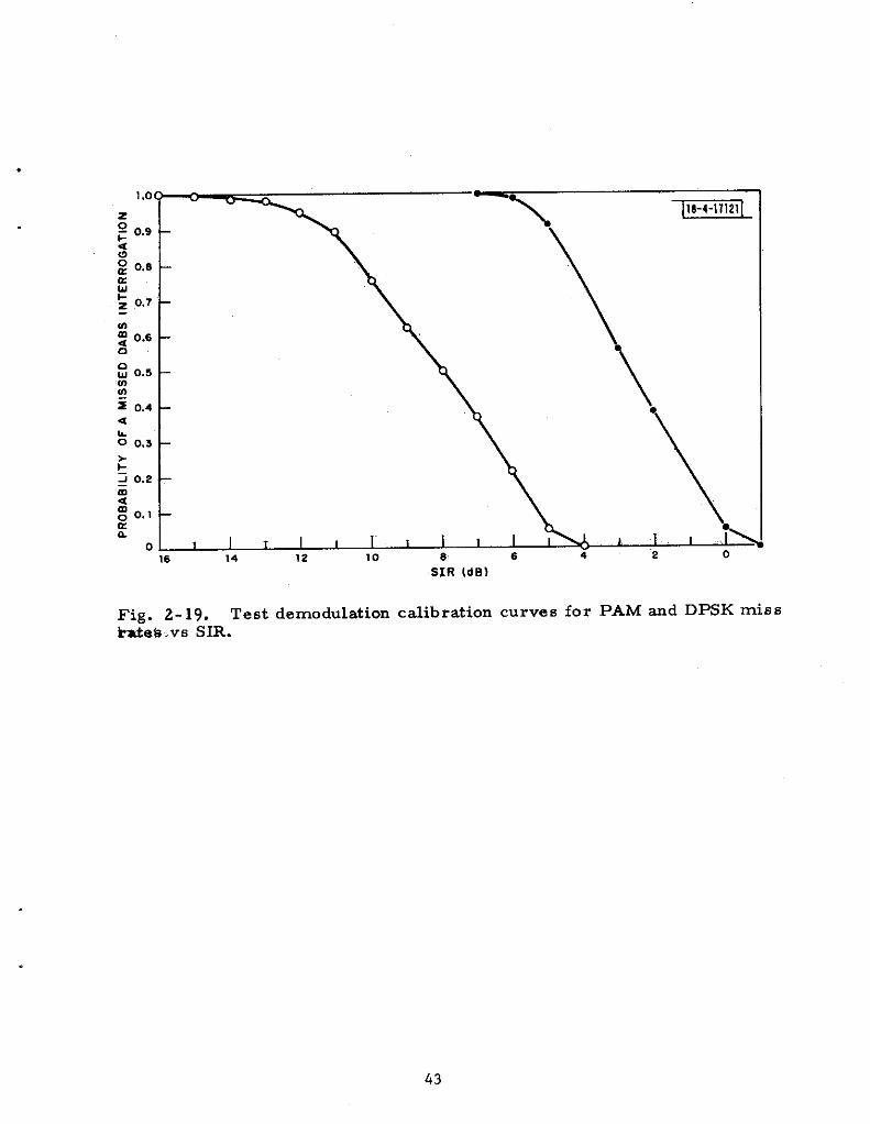
Test set demodulation calibration curves for PAM and DPSKmiss rates vs SIR
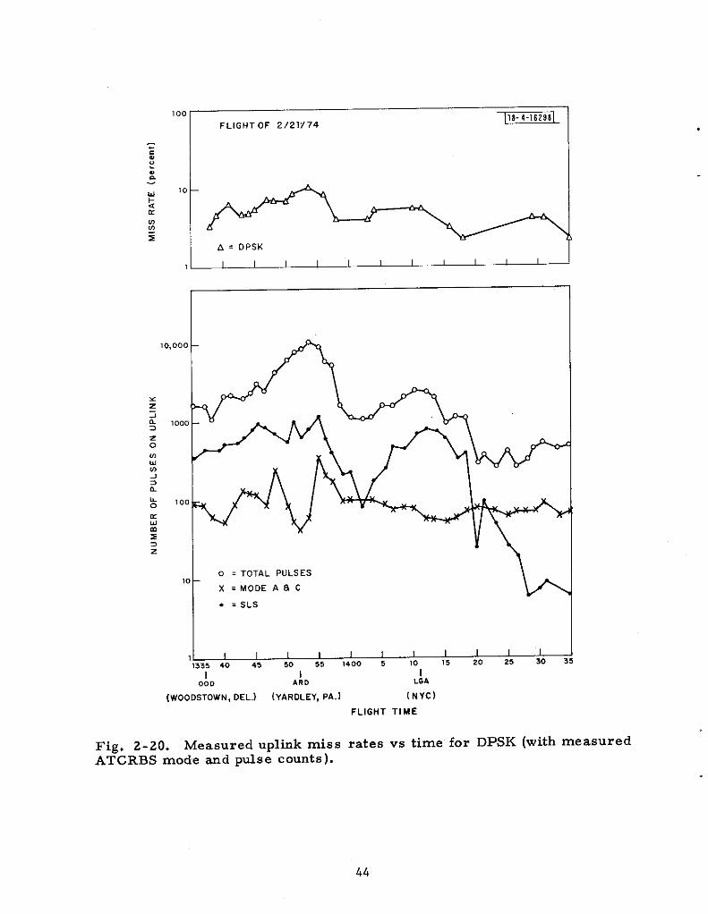
Measured uplink miss rates vs time for DPSK (with measuredATCRBS mode and pulse counts)
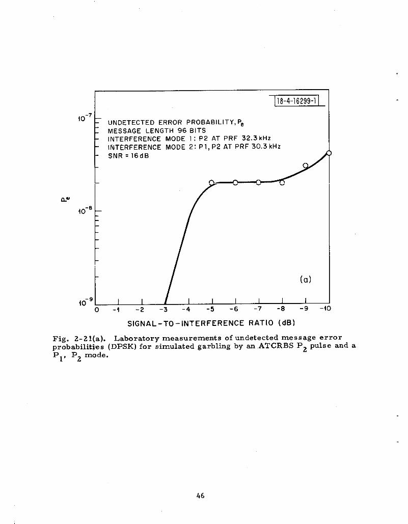
Laboratory measurements of undetected message error prob-abilities ~D=K) for simulated garbling by an ATCRBS P2wise and a PI, P2 mode
23
25
30
36
37
38
39
40
42
43
44
46
.
.
Fig.
ml(b)
2-21(C)
2-21(d)
2-21(e)
2-22
2-23
2-24
2-25
3-1
3-2
3-3
3-4
3-5
3-6
3-7
3-8
3-9
3-1o
ILLUSTRATIONS (cont. )
Page
Laboratory measurement of undetected message errorprobabilities (DPSK) for simulated garbling by two ATCRPSiuteerog~tions, eae’h w~ti Pl, P29 P3 Present-
Laboratory measurement of undetected message errorprobabilities (D~K) for simukted garbltig by two ATCRBSmode 3/A interrogations (one two -pulse and one with allthree pulses present).
Laboratory measurements of undetected mea sage errorprobabilitiess (DPSK) with two CW interfering signals
Laboratory measurements of undetected message errorprobabilities (DXK) with a single CW kterfertig signal
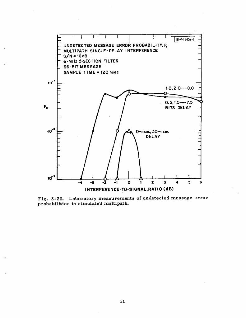
Laboratory measurements of undetected message errorprobabilitiess in. simulated multipath
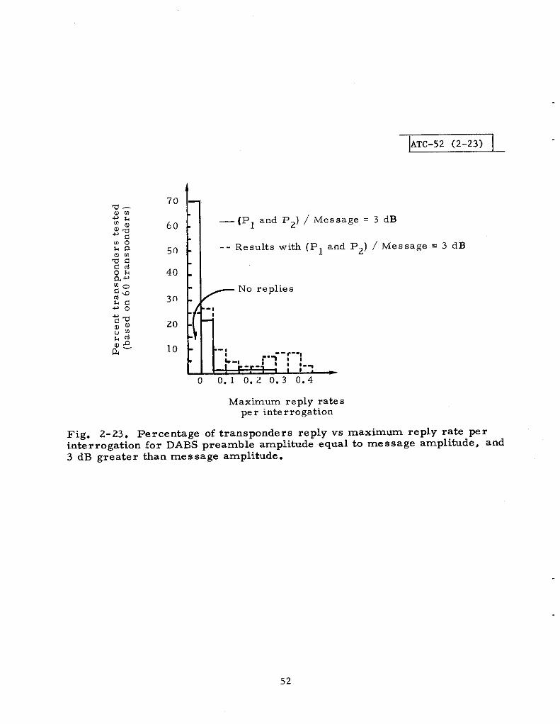
Percentage of transponders replying vs maximum replyrate per interrogation for DABS preamble amplitude equalto message amplitude, and 3 dB greater than messageamplitude
ATCRBS/DABS all-call interrogation formats
Measured change in ATCRBS transponder thresholdto DABS all-call mOde
Ef~ects of DABS downlink on TACAN/DME beacons
Present TACAN/DME installations at various sectionsof New York
DABS downlink effects on TACAN interrogator
Garble probabilitiess for DABS replies of various lengthsfor a Poisson ATCRBS fruit arrival model
Simulation re suits for bit error probabilitiess for downlinkmodulation options 2 and 3 with single ATCRBS replyinterfering (NRZ -PAM curve given for reference)
Burst error pattern generator
Four candidate downltik preamble formats
Digital preamble detector circuit for a 1O-MHZ clock
P and PF vs Y for each of the fOur candidate pre*mblesPo Fig. 3-7
Timing estimate ~rformance for Format I preamblewith 20-dB SNR, Y = O. 5, 20- ~~z sarnPI~g, and nO “fre -
quency offset
47
48
49
50
51
52
55
56
62
63
65
70
73
76
80
81
83
84.
v
ILLUSTRATIONS (cont. )
Fig.
3-n(a) Timing estimate performance of Format I preamblewith 20-dB SNR, Y = O. 5, 20-MHz sampling, and 2-MHz frequency offset ( 1 ATCRBS reply present)
3-n(b) Timing estimate performance of Format I preamblewith 20-dB SNR, 7 = O. 5, 20-MHz sampling, and 2-MHz frequency offset (2 ATCRBS replies present)
3-12 Probability of successful decoding of Format I preamblevs SNR
3-13 Preamble performance bound in ATCRBS fruit
3-14 Message decoding performance in ATCRBS fruit
2-1
2-2
3+1
3-2
3-3
TABLES
Page
85
86
87
89
90
Page
A Posterior Probability of Undetected Message Error 32
DABS/Transponder Design Cost Study Contractors 34
Simulation Re suits for the Probability of Correct DataBlock Decoding 88
DABS Reply Processor Simulation Re suits 93
Overall DABS Reply Processor Success Probability inATCRBS Fruit Based on Simulation Re suits 94
.
.
.
vi
.
.
.
.
DABS MODULATION AND CODING DESIGN (A SUMMARY)
1.0 INTRODUCTION
1.1 General
The reDort of the Department of Transportation Air Traffic ControlAdvisory Comhittee (ATCA6) of 1969 [Ref. 1] recOmmend’d an u~aradineof the Air
1.
2.
Traffic Coritrol Radar Beaco-n System (AT CRBS) to pro~i~e: -
Increased traffic handling capacity for the dense regions of air -space hy addition of a “discrete addr~ss” mOde.
Use of the discrete address mode to protide two-way ATC datalink capability to reduce the controller communication workloadand provide for the efficient automation of control functions suchas Intermittent Positive Control (IPC).
The ATCAC recommended a system design that allowed an evolutionary im-plementation in which transponders and ground sensors could be replaced ona one -for-one basis over an extended period of time, implying that the newtransponders and sensors would have to be able to work with the old ATCRBSas well as new DABS sensors and transponders.
The DABS development program [Ref. 2] is the direct result Of theATCAC recommendations. One of the major itiluences in the design ofDABS was the necessity for low-cost transponders, especially for thegeneral aviation class aircraft, to assure an acceptable cost to the users.The requirement to allow one-for -one replacement of transponders, to-gether with the transponder cost constraints, forced the combining ofATCRBS and DABS circuit functions to the maimm possible extent. Sincethe data processing of DABS associated with address checking and messagehandling has no counterpart in ATCRBS, the only possibility for combiningATCRBS and DABS functions in dual purpose circuits is in the RF and IFfunctions. Thus, from the outset of the DABS development program, theprime candidates for the DABS interrogation and reply li~s, from a costvie~oint, were the frequency channels used by the ATCRBS. A major partof the DABS liuk design effort was therefore spent investigating electro -magnetic compatibility (EMC) is sues, i. e. , the effect of DABS transmis -sions on the ATCRBS (and TACAN channels near these frequencies), and theDABS link performance in the presence of the radio frequency interference(RFI) generated by ATCRBS.
1.2 DABS Performance Goals
The specific DABS performance requirements, which were necessaryto carry out the detailed system design, evolved over a period of time afterthe ATCAC report. They may be summarized as follows:
1
I
1:
1. 2.1 Surveillance
Much emphasis was placed on improved surveillance reliability(increased probability of target location per scan), although increased sur-veillance accuracy was also sought for automated cotiict detection andresolution. The performance goals were:
. Data update interval -4 secOnds
. Probability of target location and identification on a singlescan -O. 99
. Azimuth accuracy -0.1° (rms)
. Range accuracy _ 100 ft (rms)
1. 2.2 Communication
The critical communication function identified was that of transmit-ting ATC command messages from the ground seneor to aircraft on collisionor cofiicting paths. All other messages considered for DABS were lowerin priority and in performance requirements. IPC or ATC command mes-sage requirements were:
IPC/ATC command message length _ 50 bits
Delivery requirement -0.99 probability of delivery of the correctmea sage within one s can (data update interval)
Acceptance of erroneous mea sages with probability leas than. IO-7
1. 2.3 System Capacity
The ground surveillance system based on DABS was envisioned asincorporating a fail-soft capability by providing for multiple s ens or cove r-age of aircraft whenever possible. Automatic system monitoring would beused, and network recotiiguration would automatically be done if elementsof the system failed. These features, together with aircraft traffic projec-tions into the 199os, resulted in the requirement that an individual sens Ormust be capable of handling at least 2000 DABS aircraft.
1.3 Summary
This report presents the rationale for selecting the DABS signalingwaveforms and error control techniques. Cost and equipment compatibilityconstraints placed a high premium on the use of ATCRBS frequencies of1030 and 1090 MHz for the interrogation and reply channels, respectively.
.

.
The position taken during the link design effort wae that DABS’ use of thee efrequencies would be pursued until and unless they appeared infeasible fromthe viewpoint of DABS li~ performance or from EMC considerations.
The DABS Ii* design philosophy was a conservative one thatfavored m=imizing performance margins at a ftied level of transpondercost in order to allow a safety factor for such basic uncertainties as
1. Increase in the number of aircraft,
2. RFI environment projections (for ATCRBS and TACAN),
3. Increase in the variety of functions and applications thatDABS may be required to support.
The remainder of this report covers the upliuk and do-li~ designsand presents estimates of DABS link performance in projected channelenvironments. The detailed DABS signal formats, including waveformsand tolerances, are specified in Ref. 3, and an overall description of theDABS system is given in Ref. 4.

2.0 UPLINK DESIGN
2.1 Design Options.
The two basic functions of the DABS upli~ are
1. Interrogating individual DABS transponders to obtainsurveillance data,
2. Delivering critical IPC and ATC commands (messages) toaircraft.
The most advantageous choice for the DABS upliuk operating frequency isthat of the ATCRBS (1030 MHz) from the viewpoint of transponder cost.Thus, the initial upli& design effort was directed toward the selection ofsignaling waveforms (including data modulation system” and DABS interro-gation modes), and a message/validation/error control system for 1030MHz so that DABS li~ performance achievable on this channel could beassessed. The three major considerations in making design choices were:
1. Transponder cost impact, especially the general aviation class,
2. EMC with ATCRBS and TACAN,
3. Li& performance.
The stringent transponder cost constraints reduced the data modu-lation options to the types consistent with very simple and inexpensivedemodulator implementation. Thus, only binary modulation types usingsimple waveforms were studied , i. e. , pulse amplitude modulation (PAM),on-off keying only, frequency shift keying (FSK ), and phase shift keying(PSK).
The upli+ data rate was loosely constrained by the window at 1030MHz to less than 10 MHz. Very high data rates would be more costly toimplement than low data rates, but the longer duration transmissions re-sulting from low rates would be more vulnerable to garbling and wouldaffect the ATCRBS transponders more. In studying the respOnse Of avariety of ATCRBS transponders to the binary modulation formats listedabove, it was deemed necessary to constrain the DABS uplifi data block tolie within the ATCRBS suppression interval, which is specified as35 + 10 ~sec [Ref. 5]. Thus, the transmission of approximately 100 bits inthe DABS upliuk message (24-bit address, 50-bit message, and 25-bit con-trol), within a single ATCRBS suppression interval of 25 ksec, implied aone -shot data rate of approximately 4 MHz, which was not very differentfrom the AT CRBS transponder bandwidth and would fit well within the chan-nel window. Lower data rates, together with the constraint of having to
.
transmit data only within ATCRBS suppression intervals, would necessitatetwo separate transmissions to deliver a 100 -bit data block, each one con-strained to 25 #see and separated by enough time to allow all ATCRBS
.
4

I . transponders to recover from suppression to enable them to be resup-pressed by the second transmission. Thus, a 2-MHz data rate woulddeliver a 100-bit uplink data block in two segments, each25 Wsec long and~eparatedby at least45 psec. Thus, approximately 100 ~sec would beneeded to deliver a 100-bit data block with a modulation rate constrained tO2 MHz. The slight relaxation in timing problems ingoing from a4-MHztoa 2-MHz data rate was judged too’stiall a gain to increase the channeloccupancy by a factor of four and to complicate the logic of handling mes -sages by requiring multiple segments. The single transmission of 100 bitsin approximately 25 @see was selected for the DABS uplink.
DABS surveillance required transmitting, at most, only 50 bits(24 address and approximately the same 25 bits for control),. and couldthus be accomplished with even lower channel occupancy than would berequired by mes sages, but a very slight cost penalty would be incurred inrequiring the DABS transponder to procese two different DABS interrogationlengths. The difference in vulnerability to R FI of the two lengths is ins ig -nificant in a practical sense. However, two DABS interrogation lengthswere adopted mainly to clearly distinguish interrogations from mes sages,thus lowering the probability of misinterpreting interrogations with er rorsas command messages.
The very stringent mes sage validation performance goal left fewrealistic options other than parity check coding. Error correction wasnever seriously considered for the DABS uplink because of circuit complex-ity, although error detection schemes can generally be implemented at verylow cost. The more serious .cost of coding for message validation was con-sidered to be the redundant bits, because of the tight time constraints onthe uplink data block length.
In summary, the DABS uplink design options were constrained bycost, EMC, and performance conside ration to the following scheme. DABSuplink messages (approximately, 100 bits total transmission) would have tobe transmitted in approximately 25 v see, using a simPle binary mOdulatiOnscheme with a data rate of approximately 4 MHz. Parity check coding fOrsimple error detection would b: investigated to devise a plan that wouldallow simple decoder cirguitry and require low message redundancy.DABS surveillance interrogations would be transmitted in shorter transmis -sions that would also use the parity check coding for error detection.
Including parity check coding for error detection on both surveil-lance and communication modes implies that DABS transponders will sel-dom respond to garbled interrogations or messages. The absence of areply will therefore indicate to the ground sensor the need to retransmit.DABS uplink reliability in heavy RFI conditions will be entirely dependent onthe immunity to the RFI provided by the data modulation. An efficient up-link design (one which maximizes reliability for a given cost) will result inminimum effect on the ATCRBS and TACAN operation and will also simplify
I
the DABS sensor operation. Thus the key design choice in the DABS uplinkis selection of a data modulation system that provides for the most efficientdesign in the RFI conditions.
2. 1.1 Upli* Design Philosophy
It is impossible to precisely predict the RFI environment (on 1030MHz ) far into the future. Yet it would be highly undesirable to have DABSperformance degrade seriously in heavy traffic enviro-ents, which arealso likely to correspond with heavy RFI environments. The uncertainty i$RFI environments, increase in aircraft traffic, and message traffic loads ,which DABS will experience over its operational lifetime, places a priorityon achieving an efficient li~ design in realistic channel envirouentswhich include fading, RFI, and multipath. Furthermore, an efficient DABSlink design (i. e. , one that minimizes DABS channel utilization) is desirableto minimize or at least limit DABS interference to ATCRBS and TACAN.Thus the DABS li~ design was not accomplished simply to achieve someadequate level of performance in specifically stated RFI and traffic environ-m ents. A more conservative approach was taken in which the maximumDABS li~ performance during a variety of channel conditions was soughtfor a fixed transponder cost level.
There is another critical point that affects upli~ design philosophy:once the DABS transponder specification is issued in the form of a NationalStandard, the upli~ performance is essentially fixed for the life of thesystem while it will be possible to upgrade the performance of the downliuk(at least up to certain fundamental limits) by replacement of the reply pro-cessors of the ground sensors. Therefore, it is highly desirable to incor-porate the maximm uplifi performance margin in the design consistentwith a fixed transponder cost so as to as sure as far as possible that suchlater system upgradings will not be seriously limited by the fixed upli~performance.
2.2 Electromagnetic Compatibility (EMC) Issues
The EMC issues of greatest concern to DABS are the effects ofDABS transmissions on th,e operation of the ATCRBS and TACAN systems.The investigations into these issues were conducted at two levels: the firstbeing concerned with the detailed responses of ATCRBS transponders andTACAN equipment to DABS transmissions, and the second being tbe charac-terization and assessment of the degradation of the overall (ATCRBS andTACAN) system performance resulting from DABS transmissions in termsof the DABS traffic load and link efficiency (i. e. , DABS channel utilization).
‘zPerhaps caused by as yet unforeseen applications of DABS.
.
.
,
6
.
*
2. 2.1 ATCRBS EMC Considerations
The ATCRBS specification [Ref. 5] designates the required tran-sponder responses to the standard interrogation modes of the system and toshort pulses and CW inputs. It does not, however, specify transpondercharacteristics in sufficient detail to reliably predict the effect that DABSinterrogations on 1030 MHz would have on ATCRBS transponders. There-fore, an experimental program, using a series of bench tests, [Ref. 6] wascarried out to determine these effecte on a variety of ATCRBS transponders,which included one military unit, two different air carrier designs, andnineteen different general aviation transponder designs. A later experi-mental series [Ref. 7] progressed to field tests on transponders installed, ingeneral aviation aircraft to verify the results of the bench test program.The important results of these investigations are briefly summarized here.
The single most importarit result of testing ATCRBS transponders isthat virtually any form of data modulation, if sustained long enough, wasfound to trigger these transponders. Triggering of replies has the effect ofinhibiting the transponder from replying to legitimate interrogations for theduration of its recovery or dead time (about 25 to 120 #see), and also con-tributes fruit to the reply channel. The forms of binary modulation used inbench testing ATCRBS transponders included:
1.
2.
3.
4.
5.
PAM-RZ (carrier returns to zero between pulse positions)
PAM-NRZ (nonreturn to zero between pulse positions)
PSK -CE (constant envelope)
%lsed PSK (carrier returns to zero between phase coded pulses)
FSK,
ATCRBS reply triggering was observed even for specially constructedpulsed PSK formats with 1- and 2.psec pulse spacing, which was intended
to continuously suppress ATCRBS transponders before they would be trig -gered. (Upon recovery from an initial suppression by such a pulse train,it appears that the recovery of the transponder suppression circuitry isdelayed relative to the triggering circuitry, and transponders thus tend tobe triggered rather than suppressed a second time. )
This triggering phenomenon was exhibited consistently enough by asufficient number of different transponder designs that the possibility of anIIinvisible II DABS interrogation waveform (one that neither triggered nOr
suppressed ATCRBS transponders) was firmly ruled out. The next mostappealing approach was the adoption of a preamble for the DABS interroga-tions, which intentionally suppresses ATCRBS transponders, providing aninterval of time (the transponder suppression interval) in which the DABSdata could be transmitted without further effect on the ATCRBS transponders.
7

The ATCRBS suppression interval is specified as 35 + <0 Msec. Inorder to avoid triggering a Mode-2 reply in any military transponder meet-ing this specification, the DABS data block following the preamble suppres -sion pair would have to be no more than approximately 29 # sec (25 psec forthe minimum suppression interval plus 5 vsec could trigger Mode 2). Civiltransponders, which respond to only Modes 3/A and C, would constrain theDABS data block to approximately 32 ~sec. The limit for the duration of theDABS data block following a suppression pulse pair was measured for avariety of .4 TCRBS transponders; Fig. 2-1 illustrates some of these mea-surements. Although the data in Fig. 2-1 was acquired using a 4-MHzPAM-NRZ data modulation, the results are essentially the same for PSK orFSK. The measurements indicate that the DABS data block is constrainedto a length of approximately 30 v see, (or the overall interrogation is con-strained to approximately 33 #see).
U several successive DABS transmissions were to be used todeliver one uplink message, the interval between DABS transmissions mustbe long enough to assure resuppression of ATCRBS transponders, with thelongest allowable suppression interval of 45 PSe C. Thus, if mOre than Onetransmission of approximately 30 ~sec is needed for upliuk messages, thenthe channel occupancy of DABS increases sharply for each message.
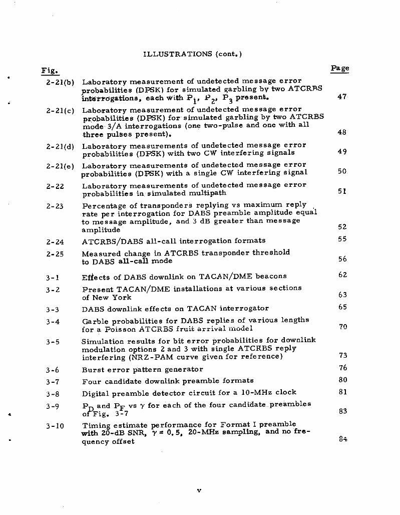
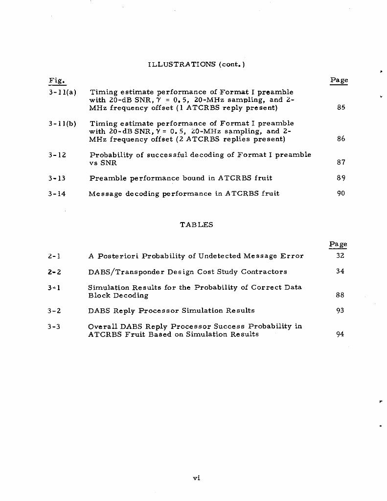
A simpler message transmission plan (in a link protocol sense)would be to use a sufficiently high upli~ data rate to include a completemessage (including address and control bits) within a 30-Lsec interval. Themain effect that DABS upli& transmissions would have on ATCRBS would beto keep transponders suppressed a fraction of the time. The worst effectwould be that those AT CRBS’transponders at very close range to a DABSsensor (which could receive transmissions in the side and backlobes of thesensor antenna) may be suppressed by nearly all DABS transmissions. Thefraction of time that an ATCRBS transponder would be suppressed by asingle sensor in this worst case in indicated in Figs. 2-2a, and -2b as afunction of the number of DABS transmissions per second and as a functionof the total aircraft load handled by the sensor. For highly reliable DABSli~ operation, even” a traffic load of 2000 aircraft for a single sensor doesnot keep an ATCRBS transponder suppressed more than a few percent of thetime. of course, the total effect of many DABS sensors must be con-sidered by the system de figner, but it is viewed as unlikely that DABSsensors would have to be deployed s o closely spaced that an aircraft couldbe simultaneously within range of the side and backlobes of many sensors.It is clear that efficient DABS link operation requiring few repeated uplinktransmissions and low sensor ERP tend to reduce the total ATCRBS tran-sponder suppression effect by a network of DABS sensors.
.
.
DABS MESSAGE WAVEFORM: 2 Mblsec NRZ-PAM
INTERROGATION LEVEL: -50dBm
z -- *g
-- AVERAGE REPLY RATE (I4 Transponders)
+ 0.4 —aw:aukz- 0.3 -e APx-72ua
m~
:~ 0.2 -aLo
awmz 0.1 -
z & —START OF OABS INTERROGATION(Preamble)
- START OF OABS MESSAGE
1 I I I I I- -3., !5 a 5 to 15
MEISSAGE LEN GTH (~SOC)
APX-72 I
621-A6
I
MEASUREO
AT-50~E:;:;:SION
AVQ-65
Fig. 2-1. Measured ATCRBS transponder triggering rates vs interrogationlength (following a pulse-pair suppressing preamble).

ATC-52 (2a)
DABS transmissions per second
Fig. 2-2(a). ATCRBS transponder suppression in side and back lobes of DABSsensor.
ATC-52 (2b)
E .+.-
~ ; 0.075 ~~”.15 :
~Total aircraft handledby DABS sensor
~
Fig. 2-2(b). ATCRBS transponder suppression as a function of DABS sensOTtraffic loading and reliability.
10
.
.
.

2. 2.2 TACAN EMC Consideration
Acting in direct support of the DABS program, ECAC* has investi-gated the effects of DABS in TACAN/DME. The investigations have beenprimarily analytical in conjunction with laboratory measurements accom -
The following material is based on an ECAC report~~~p!]a~i;~?$;rim results.
A. Major Effects of DABS Uplink Transmissions
The major effects of DABS uplink transmissions on TACAN/DME(ground based) beacons are:
Loading (replies to decodes produced by DABS signals)
Deadtime moth the deadtime associated with replies anddeadtime caused by dynamic desensitization)
The major effect on TACAN/DME (airborne) interrogators is:
AGC capture (according to an effective average inter-ference power)
Because of the durations and signal structures of DABS uplink trans -missions, it is possible that decodes and resulting’ replies will~be producedin TACAN/DME beacons. Similar decodes may also be produced by DABSsignals in TACAN/DME interrogators, although thes e are of little cons e -quence relative to the AGC capture phenomenon. Beacon decOdes are PrO-duced only when a DABS sigrial is received at sufficient power after theeffects of path loss, antenna gains, and frequency filtering. Consequently,tbe re suiting occurrence rates depend on location of the equipment andchannel number as well as on transmitter power levels, antenna patterns,and DABS interrogation rates.
Laboratory measurements have demonstrated that the dominantinterference effect of DABS uplink signals acting on TACAN/DME interro-gators is AGC capture. The occurrence. of this condition may be determinedby calculating an ,[effective average interference power, “ (EAIP). TbeEAIP is calculated as th..s~eceived average power level, adjusted for off-frequency rejection (OFR) and then adjusted for receiver saturation. M theEAIP exceeds an empirically determined m-imum tolerable level, Max(EAIP), which depends on the power level of the TACAN/DME signal beinginterfered tith, then a degradation condition exists. The manner of degra-dation that occurs just beyond Max (EAIP) is the inability to acquire azimuthlock. Other degradations such as azimuth breaklock, inability to ac,quirerange lock, and range breaklock all occur at higher levels of interference.
ZXElectromagnetic Compatibility Analysis Center, Annapolis, Md.

B. Degradation Criteria
For TACAN/DME interrogators, the degradation criterion used issimPly that EAIP < Max (EAIP). Lesser amounts of average interferencepower have no dis ce rnable effect on interrogator performance.
For TACAN/DME beacons, it has been difficult up to the presenttime to select a single specified level of loading and deadtime for use as adegradation criterion. Consequently, re suits generated by ECAC give load-ing and deadtime parametrically. ECAC is conducting a parallel effmt:toinvestigate the effects of deadtime and loading on the ove rail TACAN/DMEfunctioning. The objective is to determine whether or not given levels ofloading deadtime produce a noticeable effect on ove rail performance. Re -suits available at this time suggest that if deadtime and loading are bothapp-imaaly 5 ~., very litile M any noticeable effe Ct would re SU~?; b Y itsnature, the TACAN/DME system is very tolerant to interference.
c. Estimated Levels of Interference
Based on reasonable assignments of transmitter powers, antennapatterns, DABS interrogation rates, etc. , ECAC has calculated beaconloading and deadtime as functions of range and frequency offset. The cal-cuktions include pme r programming and include a retire of long andshort DABS interrogations. Typical results are shOwn in Fig. 2-3. Evi-dently the interference effects are quite small, such that in this case, in-band operations are also possible without exce.e’ding tie 5 % loading -deadtimecriterion mentioned above. Furthermore there is a hrge @FR improvementfor out - of-band channe 1S.
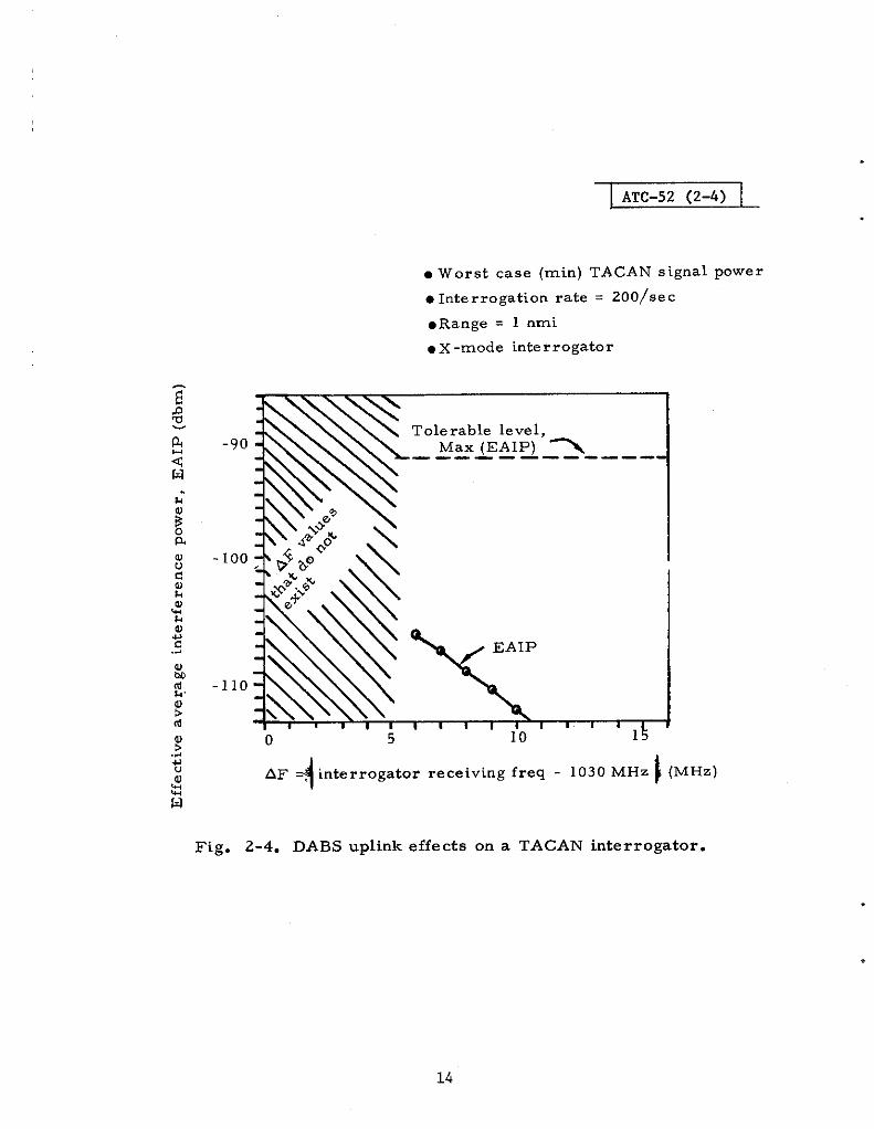
Simihrly, ECAC has calculated interference conditions received atan airborne TACAN/DME interrogator. Typical results are given in Fig.2-4. The data in the fi~re indicate interference conditions that are-muchless than the tolerable level, even for the smallest existing frequency off-set (in this case 6!MHz). Whereas Fig. 2-4 pertains to an X-mode inter-rogator, ECAC has. determined that the effects on a Y-mode interrogatorare completely negli @ble.
2.3 Modulation Characteristics
Transponder cost constraints and EMC considerations lead one touse simple bimry modulation s qhemes for transmitting DABS uplink mes -sages at a data rate of appr~imately 4 MHz. Emphasis kust be placed notonly on simple demodubtor” circuitry to keep transponder r cost down, buttie selected system must also be sufficiently insensitive to synchronizationerrors to allow the use of simple synchronization circuitry as welL. Thissection discusses the relevant performance measures of several binary mod-ulation candidates for the DABS uplink.
12

ATC-52 (2-3)
oWorst case (rein) TACAN/DME signal power
●Interrogation rate = 200/sec
.Range = 1 nmi
I +I I I 1 1 I , I I
o 5 10 15
F = I beacon receiving frequency - 1030 MHz I (MHz)
13
Fig. 2-3. Effects of DABS uplink On TACAN/DME beacOns.
ATC-52 (2-4)
● Worst case (rein) TACAN signal power
● Interrogation rate = 200/sec
●Range = 1 nmi
. x -mode interrogator
Tolerable level,-90- Max (EAIP) ~—--— -——- -— —--
100
110
0 5 10
4AF -, interrogator receiving freq - 1030 MHz } (MHz)
Fig. 2-4. DABS uplink effects on a TACAN interrogator.
.
14
.
.
.
The channel environment at 1030 MHz will include the following effects:
1. Fading caused by antenna shielding and lobing
2. Rlsed RFI from ATCRBS interrogation
3. Multipath garble, (the degree of severity of which is unknown andis determined by DABS sensor antenna design and siting).
Furthermore, EMC conside rations dictate the use of minimum sensoreffective radiated power (ERP) to minimize ATCRBS side - and backlobe sup-pression range. Thus, the relevant performance measures for a first com-parison of modulation schemes are error rates (probability of bit decision
y;;gr;~tibkii~~~~nction of signal-to-noise ratio (SNR) and signal-to-.
Since the ATCRBS interrogation mode decoding generally used a PAM-type demodulator, and the military Mode 4 interrogation is a discretelyaddressed interrogation using a PAM-RZ format, the initial bias for theDABS uplink modulation was in the direction of a PAM system. For DABS,PAM -NRZ was more advantageously suited to the 4-MHz data rate because itallowed smaller bandwidth occupancy than an RZ format would allow at thesame data rate. Thus, the PAM system considered for the DABS uplinkwould transmit a particular information bit by the presence or absence of anRF pulse in a particular interval. In an NRZ format, successive bit inter-vals follow one another without spaces between them. The PAM demodulatorwould process the pulse incoherently (do envelope detection), sample theenvelope video at a point within the bit interval, and compare the samplevideo amplitude with a threshold to decide whether or not a pulse was pre -sent (i. e. , whether or not to decide the information bit was a one or a zero).Good performance in the presence of RFI requires that the decision thresholdbe a function of the received signal level. The PAM demodulator itself canbe quite simply implemented, but both the bit synchronization (the sampletimes) and the decision threshold setting must be provided by other circuitry.Moreover, in a system such as DABS, in which the path 10SS varies over awide range because of the target range from the sensor, the PAM processingcircuitry must preserve the envelope fidelity over a wide dynamic range, orenergy from adjacent pulses will make it difficult to recognize the absence ofpulses (this effect is called inters ymbol interference). Because of the 4-MHzdata rate required by the DABS uplink, a simple modification to existingATCRBS or Mode 4 decoders would not be possible. Therefore, PAM had tobe considered on its own merits just as any other system that would requirea new synch/demodulator system in the transponder.
In FSK, one of Wo discrete RF pulse frequencies is used to transmit
a particular infOrmatiOn bit. A simple demOdulatOr wOuld cOmpare the Outputsof NO filters tuned to the frequencies to make its bit decisions. Thus, thereis no threshold setting in accordance with received signal level, which is asimplification. The use of simple filters in the demodulator is facilitated b y
15
increasing the frequency separation of the pulse, but this happens at a costof increased bandwidth occupancy, which might affect EMC problem~.
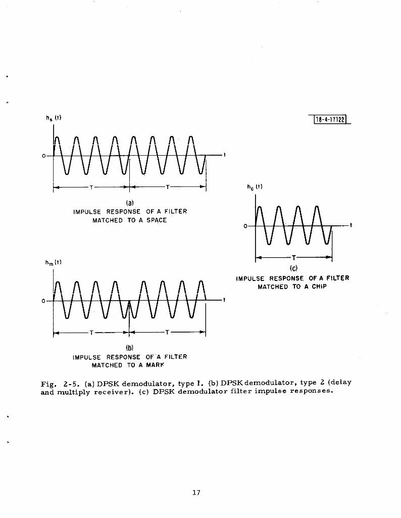
In PSK modubtion, the RF phase of a pulse is” controlled relative to areference signal to transmit information. In a binary system, one of two RFcarrier phase angles 1.80° apart is transmitted to signify the value of a par-ticular information bit. In cdkerent PSK, a carrier phase reference must beestablished by the receiver. The time constraints of the DABS uplink andthe complexity associated with this reference signal ruled out coherent PSK.However, the simpler differentially “phase shift keyed variant, termed DPSK,uses the RF phase of the previous pulse as the reference in making bit de -cisions, thus simplifying the phase reference problem somewhat. A D~Kdemodulator thus compares the carrier phase of a pulse with that of the pre -vious pulse and decides whether or not the pulse phase is clOser tO being inphase or 180° out of phase with the reference pulse phase. TWO cOmmOntypes of DPSK demodulators are shOwn in Fig. 2-5. Neither Of these de-modulator types requ,ires the setting of a decision threshold dependent onreceived signal level. Moreover, a saturating limiter can generally be usedto restrict the dynamic range of a DPSK demodulator while not seriouslyaffecting performance in RFI.
Fi are 2-6 shows the probability 0! a bit decisiOn ?rrOr, ‘e/&it’ .as affunction o SNR (given by the energy per blt E over the noise power enstty
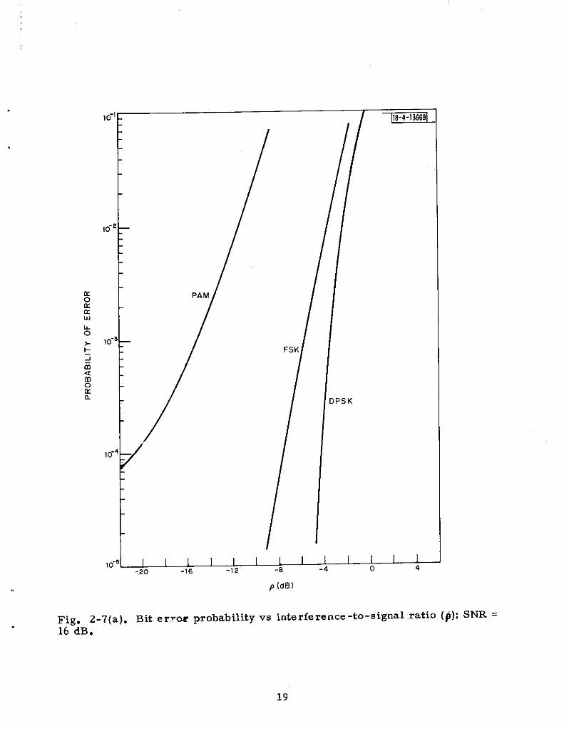
No) for ideal processing of incoherent PAM and FSK, and DPSK [Ref. 9].In this case ideal processing implies ideal matched filters in the demodula-tors, perfect bit synchronization, and perfect setting of the decision thresh-old in the PAM demodulator. FiWre 2-6 als O ipdicates sensitivity tO inter-ference of the various modulation types for an ISR (denoted by pin the figure)of 0.2. Fi~res 2-7a and 7b show Pe/bit as a function of ~R (interference-to-signal ratio (ISR) = SIR-l) for SNR(S) Of 16 dB and 24.8 dB. Again idealdemodulators were assumed. The se calculations show Mat DPSK attains a
igiven level of Pe bit in the interesting range Of 10-3 and 10-5 at significantlylower SNR(S) an SIR(S) than the other two schemes.
FSK displays no performance advantage over the other candidates,although it may aggravate some EMC” problems. Since it also promises nosignificant cost advantage, if any at all, FSK was dropped from further con-side ration.
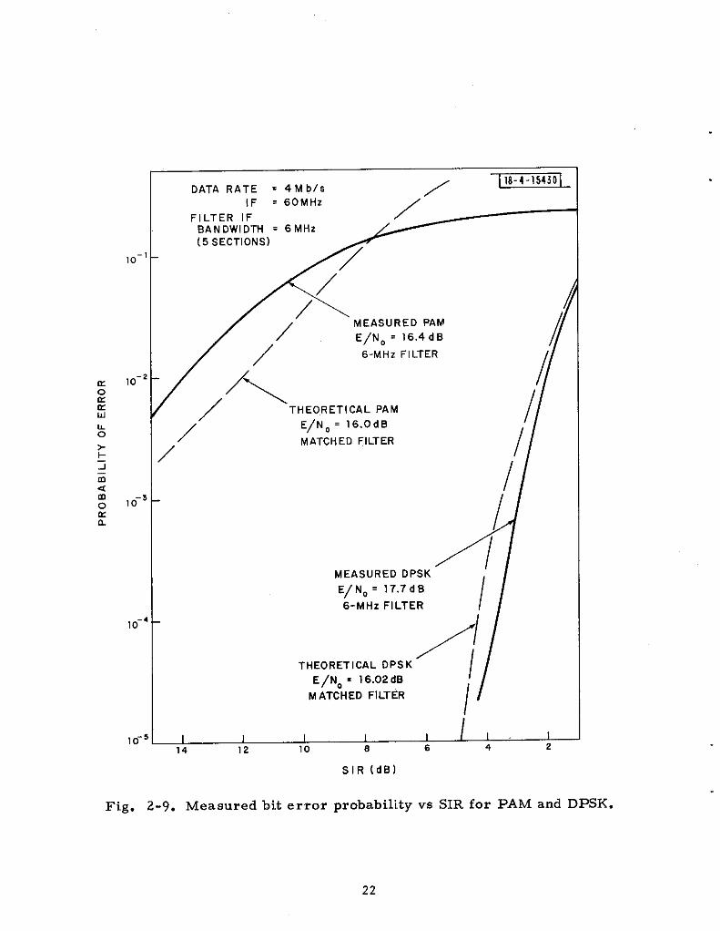
In order to assess the difference between ideal and real demodulatorperformance, PAM and DPSK demodulators were built arid te steal at LincolnLaboratory. The ideal matched filters were replaced in the Laboratorydemodulators by 5-section, 6-MHz bandwidth IF filters. Figures 2-8 and
2-9 show both calculated and measured values of Pe/bit as a functiOn Of SNRand SIR for demodulators with 6-MHZ filters. These results are for perfectbit synchronization and PAM thre shOld setiing. The sen~itivitY Of the Labor-atory demodulators (with 6 -MHz filters) to bit synchromzation errors ISillustrated in Fig. 2-10, which plots Pe/bit vs demodulator sample time fora 4-MHZ data rate. Figure 2-10 indicates that the Performance Of bOth PAM
16,
annc
Line
annc
Line
h, [t)
o t
hc (t)
(a)IMPULSE RESPONSE OF A FILTER
MATCHEO TO A SPACEo
h
?
hm [t) +T~
I (c)
IMPULSE RESPONSE OF A FILTERMATCHED TO A CHiP
o t
(b)IMPULSE RESPONSE OF’A FILTER
MATCHED TO A MARK
17
Fig. 2-5. (a) DPSK demodulator, type 1. (b) DPSK demodulator, type 2 (delay-d multiply receiver). (c) DPSK demodulator filter impulse responses.

10”’- ]18-4-lj6661
\
\
-\\\
‘\
\\\ \
\.PAM (Peak Power Limited)
‘\’\h\ ,= 0.2
10-4F
i\
DPSK\
‘$;;;M,M
\~=o
\\ \\ \~
\ \
\\
\\\\
\10”5—
\ \ \\
\\
\
\\
\\
I I 11{”1
J\l,\
\\\ ‘:<
1667 9 11 13 15 17 19 2
E/N. (dB)
Fig. 2-6. Probability of bit errors for tiree binary modulations in noiseonly (p= O); in pulsed interference (P=o. 2) o? I(SIR = -14 4*).v9 SNR.
10-5 I I I I I I [ I I I I I 1-20 -16 -12 -6 -4 0 4
P (dBl
Fig. 2-7(a). Bit erru probability vs interference -to-signal ratiO (#); SNR =16 dB.

FSK
,O-e
10-3— V. APPROX. OPTIMuM
10-~-
,0- 5_
Fig. 2-7(b). Bit error probability vs interference -to-signal ratio (p); SNR =24.8 dB.
20
,,
.

.
10-’
10-2
10-’
10-’
16
MEASURED PAM ~
6-MHz FILTER
:\
CALCULATED ‘PAM
\
\“
CALCULATED DPSK6-MHz FILTER
MEASURED DPSK6-MHz FILTER
THEORETICAL DPSKMATCHED FILTER
\,/, \,
\
\4 DATA RATE = 4Mbls
IF = 60 MHZ
FILTER IFBANDWIDTH = 6MHz(5 SECTIONS)
\
5 1 I I I I I
2 4 6 8 10 12 14
E/N. (dBl
Fig. 2-8. Measured bit error probability vs SNR for ‘PAM and DXK.
10-
10-
10-
1o“
10“
DATA RATE = 4Mbis /118-4-154301
IF = 60 MHZ
FILTER IF /BANDWIDTH = 6MHz /~
K(5 SECTIONS)
/
/
,//
MEASURED PAM I/
/
E/NO = 16.4d B
/’
/
/6-MHz FILTER
/\I
/THEORETICAL PAM
E/NO= 16.0d B I
,/ MATCHED FILTER/
/
/
4I
MEASURED DPSK
E/NO= 17.7d0
6-MHZ FILTER //
/
/THEORETICAL OPSK
E/NO = 16.02 dB /
M ATCHEO FILTER
/
.5 I 1 I I I / I I14 12 10 8 6 4 2
SIR (dB)
Fig. 2-9. Measured bit error probability vs SIR for PAM and DPSK.
22

DATA RATE = 4Mbl~ ] 16-4 -154jll
IF = 60 MHz
FILTER IFBAN OWIDTH = 60 MHz[5 sECTIONS)
DEMODULATED PULSE WIOTH =250 nsOC
\
—— OPSK
‘\/
/
i
SAMPLE TIME FR,QM START .OFDEMODULATEO PULSE [nscc)
Fig. 2-10. Measured bit error probability vs bit sample time (synchronizationoffset) for PAM and D~K laboratory demodulators.

I
and DPSK demodulators degrades the same amount with sample time offsetat a given level of performance (i. e. , the PAM and DPSK curves with rein+ima in probability of error of approximately O. 3 x 10’2 track together fairlyclosely, although the signal -to -noise ratios required to achieve these curvesreflect the 6 -dB advantage of D~K ).
The critical component in the simple delay -and -mtitiply DPSkdemoddator, is the delay line. The stabflity of tie delay line, with environ-mental conditions, is directiy related to demoddator performance and cost.
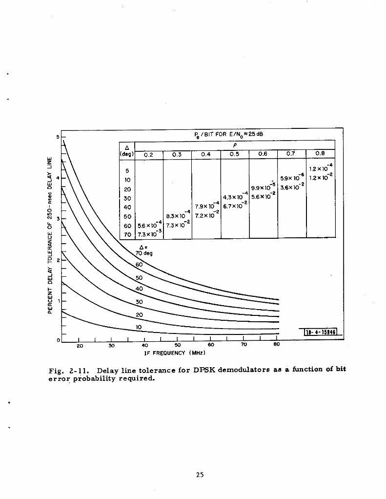
Figure 2-11 illustrates the sensitivity of the delay -and -mdtiply DPSKdemoddator to delay line variations, which resu2t in phase reference errors[Ref. 10]. The table in the figure illustrates the delay line tolerance that isrequired to maintain satisfactory demodulator performance in the presence ofRFI. At an MR value of -6 dB, these data indicate that a delay error re -sdting in less than 60° (of carrier reference phase sh~t) would be needed toassure a Pe/bit of 10-3 or less at an SNR = 25 dB. For a 60-~z IF fre-quency, this translates into a 1% tolerance on We delay l~e over all environ-mental conditions.
2n summary, the study of simple moddation schemes for the DABSuplink RFI environment restits in two candidates: PAM- NRZ and DPSK.DPSK indicates a clear performance advantage over PAM in both SNR and S~required to achieve a particdar error rate. Both schemes are ,basicallyequally insensitive’ to synchronization errors. The PAM system requiressetttig the decision threshold in accordance with the received signal level inorder to achieve its calcdated performance fi RFL DPSK does nOt requiresuch threshold setting. DPSK is less sensitive than PAM to wide dynamicrange effects of the system. The cost of the DPSK demoddator is greafiyaffected by the cost of a stable delay line. Cost comparisons will be treatedin more detail in Section 2. 5. 1 of this report.
2.4 Message Validation
The critical nature of IPC and ATC command messages for collisionavoidance requires that messages containing errors be screened and rejectedwith rest reliability. me performance goal of accepting no more than one
fin 10 messages containing errors under realistic channel conditions basicallyseeks to reduce such events to very unusual and rare occurrences. Messageerrors were anticipated from several different situations:
1. Low SNR (fading) conditions resdting in randomly distributederrors throughout the message block
2. ATCRBS interrogations and TACAN transmissions garbling,which would resdt in clusters or bursts of errors caused bythe individual pdses of these signals
24
5 Pei BIT FOR ElNo~25dB
1 1 .
II
-4 “-”” ‘--2
1:
4.3 x 10 5,6X1O
7,9X 10⁻⁴ 6,7x10⁻²
~
o I I I I I I I I I I I I I
20 w 40 w eo 70 80
0;7
5.9x 10⁻⁶
3,6x 10-Z
O.B
1.2X1O
1.2X1O
IF FREOUENcY (MHz)
Fig. 2-11. Delay line tolerance for D~K demodulators as a finction of biterror p~obability rewired.
25
3. Multipath transmission garbling, resdting in rando~y
distributed errors throughout the interval in which thedirect path signal is garbled or overlapped by thereflected path signals.
Two approaches to message validation tiat received serious considerationwere
1. -rity check codtig to detect mdtiple error bursts as well asrando~y distributed errors
2. Message parroting (repeating the message to the ground whereit is checked for errors, followed by transmission of an ex-ecution command when the correct message has been repeatedto the ground).
Of the two approaches, the first offers the potential of acceptance, validation,and display of a message followtig a single error-free uplink transmission.The parity check coding approach thus resdts in message delivery timesthat are not dependent on the dowtifnk reliability, This approach alsorequires fewer total transmissions to deliver a message, consequentlyreducing interference to other systems. The message parroting approachsuffers from having to establish a more complicated link protocol to enablethe ground equipment to do the error checking while the aircraft withholdsaction on the received message. This approach also requires increasedchannel utilization and an urineces sary dependence on downlink reliability todeliver critical uplink messages.
A third approach to message validation was very briefly considered,namely, uniformly distributing the transponder address bits throughout themessage block. Thie was intended as protection against bursts of errors,which would tend to garble at least one address bit, thus rendering themessage unacceptable to its designated” receiver. However, this approachoffers no special protection against the random pattern of errors caused bylow SNR conditions, therefore some form of parity checking would probablybe included for this case. Thus, this approach was excluded in favor of themore systematic parity check coding approach to detect both error burstscaused by RFI and noise-like error patterns.
The selected approach to uplink message validation was parity checkcoding, which was capable of detecting mdtiple bursts of errors in amessage block, as well as the randomly distributed errors caused by noiseand multipath. The coding effort focused on simply implemented errordetection circuitry consistent with transponder cost constraints.

2.4. I Parity Check Coding
A parity check code, which is intended to protect a sequence of kmessage bits, “encodes” a message by producing a sequence of n bits, wheren > k. The first k bits of the encoded sequence may be identical to the origi -W1 message, in which caee the code is called a “systematic” code. Theremaining n-k bits, referred to as parity check bits, are redundant bite thatare derived from the first k bits by a specified algorithm. Mter transmit-ting the encoded bits to a receiver, the received sequence of n bits ie pro-cessed as follows. The first k received bits are used to generate n-k paritycheck bits, which are compared to the n-k parity check bits received overthe channel. U these two parity check sequences agree bit by bit with eachother, the received sequence is self-consistent and is assumed correct. Uthe two parity check sequences disagree, an error in transmission of atleast one of the n bits has been detected.
Out of a total of 2n distinct binary sequences of length n, there areonly ~k legitimate encoded sequences that are actually transmitted. Thus ~
it is possible for channel noise or ~~1 tO change O~eencoded sequence intoanother sequence since there are 2 1 such remalnlng sequences that arelegitimate. Such a transformation of one encoded sequence into anothersequence would result, in accepting the received sequence as a correct mes-sage, although it was not the message that was transmitted. Thue theaccepted message would be erroneous, and the acceptance of such erroneousmessages is precisely the type of situation the parity check code must bedesigned to control.
The parity check code design problem may thus be stated as follows.Study encoding algorithms that will reduce the probability that channel errorsources will transform one encoded sequence into another to a suitably lowvalue, and select the code (encoding algorithm) that accomplishes this objet -tive with a minim~ number of redundant bits (n-k).
2. 4.2 Address -Parity Overlay
Since the DABS uplink transmissions were greatly time -constrained,the amount of redundance required was of primary concern. This motivatedthe acceptance of a technique proposed by British workers and used in theADSEL system [Ref. 11], which is a British develOped ATC discrete addressbeacon system. With parity check coding, a DABS transponder (or any dis -cretely addressable receiver) muet check the parity sequence as well as theaddress bits received before accepting any message. Since parity checkingand address checking are very similar operations (determining if a sequenceof bits agrees entirely with some prescribed reference sequence), the parityand address fields of an encoded message may be combined to save trans-mitting redundant bits. H the parity check sequence of an encoded mes sageis combined with the transponder address by modulo two summation, thetransponder can remove the parity check bits by modulo two summation ofthe parity check sequence derived from the received k message bits. U theparity check bits calculated in the transponder agree exactly with the parity
27
check bits that have been combined with the address, the result of summingthe two parity check sequences produces the transponder address unchanged.Thus, if the received message is entirely correct, the transponder canremove the parity check bits, and only the address bits need to be checkedto accept the message.
Ha received message contains errors, the parity check sequencederived in the transponder will disagree (with high probability) with 4hatcombined with the address, and the result will be that the address fieldchecked by the transponder will contain the transponder address s-reedmodulo two with the difference between the proper parity check sequenceand that derived in the transponder from the incorrect message. Thus, thetransponder will not find its address if the encoded message sequence hasbeen received with errore. This scheme eliminates transmission of eitherthe parity check sequence or the transponder address (whichever is smaller)as a separate bit field, This scheme was judged to be well suited to thetime-constrained DABS uplink, and therefore it was adopted and is referredto as the “address-parity overlay (I scheme to minimize the length of the
encoded uplink message.
A penalty associated with the address-parity overlay scheme is mis -directed messages catied by transmission errOr, i. e. , an encOded mes-sage addressed to one aircraft may be received by another aircraft witherrors in the received message, which result in changing the address of thefirst aircraft into that of the second aircraft. Thus, the address-parityoverlay may result in acceptance of a message containing errors that wasreally intended for another aircraft. It is difficult to quantify this phe nom e -non, but it appears reasonable to consider an erroneous message decoded bya transponder as one in which the address bits have been completely ran-domized. Thus, if such a message is to be accepted by another transponder,the probability of that transponder’s address agreeing with the scrambledaddress decoded from the erroneous message would be 2-A, where A is thenumber of address bits used by the s~>tem (under the assumption of com-pletely random scrambling by the disagreeing parity check sequences).Thus, if A= 24’bits, the probability of a misdirected messag $beingaccepted by a transponder is on the order of 2-24S 0.6 x 10- . It is truethat more than one transponder may receive a message intended for somespecific aircraft, but this is offset somewhat by the fact that there is someprobability less than unity that such messages are. received erroneously.The conclusions that a24-bit address appears to lead to sufficient controlof the probability that a transmitted message will be misdirected to someother aircraft by channel er”rors.
A further point to note concerning the address -parity overlay schemeis that the parity check sequence derived from the mes sage is available onlyafter processing the message bits. Thus, the logical location of the address -parity field is at the end of an encoded message. This implies that a tran-sponder must store and process the entire received message before it cancheck the address to determine if it should accept the message. Even if the
address were at the beginning of the message blOck, early rejection of a mes -sage address ed to another aircraft would not necessarily allow immediateprocessing of another aircraft message because the overlap of the two trans -miss ions would likely result in errors. fius there is no practical differencebetween having the address at the beginning or at the end of a message block,although there is a very significant saving in ove rail encoded message lengththat accrues from the address -parity overlay scheme.
2. 4.3 The Selected DABS Code
Binary cyclic codes are a special class of pari@ check codes, whichare generally well suited to burst error detec~lon and also admit simple de-code r circuit implementations. A further advantage of this class of codes isthe flexibility of shortening the codes to suit established message lengthrequirements while not compromising code performance. Thie propertywas benefit ial in that it allowed codirig studies to continue uninterrupted duringthe evolution of the uplink message length.
The code selected for the DABS uplink is a cyclic code generating 24parity check bits, which makes maximum use of the address field to in-corporate the reduna.nt parity bite. The particular cyclic code selected isspecified by its generator polynomial
g(x)= ltx3tx 10 t X!”2 tx13 tx14 tx~ t X16 tx’7
tX18 tx19 txzo tx~l t.x22 tx~s tx24 .
This code produces code words with a natural length of about 2.75 millionbits, but it has been shortened for use with 88 -bit messages (for a totilencoded message length with address-parity overlay of 112 bits ). This codeis also used to endode the 32 -bit DABS interrogations that do not containcommand messages. me mdtiple burst errOr detectiOn capabilities Of thiscode, discovered by Kasami, have been extensively studied and are veryw dl suited to the DABS uplink channel RFI environmefi- [Ref. 12].
Figure 2-12. illustrates the encoding circuitry associated with the DABSuplink code. The basic circuit, which computes the parity check sequencefrom the message sequence, ie a sMft register with feedback cOnnectiOns backto its input. The details of the addrese -parity overlay logic for the uplink werechoeen to facilitate the address checking in the transponder with feed-out shiftregister circuits.
2. 4.4 Code Performance
The DABS uplink code performance was estimated when the DABSuplink transmies ions were garbled by A TCRBS interrogations and TACANpulse pa~s. Performance evaluation cons is ted of calculating the probabilityof acceptance of a DABS message containing errors (undetected messageerrors ) ushg known properties of the code. ATCRBS pulses were assumed tocause error bursts up to a length of 5 bits, and TACAN pulses were assumed
~
1. tO cause error bursts up to a length of 19 bits. The probability of’ a bit errOrJwithin the burst, garbled by an interfering pulse, was assume to be O. 5 for
this calculation.
The calculated probability of undetected message err~rs is indicatedin Table 2-1 for the most probable garbling signals, which are (for ATCRBSinterrogations):
1. A single P2 pulse
2. A PI, P2 pulse pair
3. A PI, P3 pair for modes 2, 31A or C
4. A complete mode garble (Pl, P2, and P3) fOr modes 21 31A
5. Combinations of two of any of the above modes.
Table 2-1 indicates the calculated conditional probability of an undetectedmessage error, assuming that a garble occurs, i. e. , the probability thata garble will occur in a given environment is not included in these results.In addition, the conditional #robabilit y of undetected message error, givena garble by a TACAN mode , is less than 2.14 x 10⁻⁸. The calculation Ofthese results is described in more detail in Ref. 13. (It should be notedalso that the above calculations were dOne fOr a 96-bit encOded messageblock, which does not result in any practical difference in calculated per -formance for 112 bits for the coding s theme selected. )
The aforementioned results demonstrate that the selected DABSuplink code appears to be well-matched to ‘the error detection function forthe DABS uplink RFI environment. The performance goal of undetected mes -sage error probability of 10’7 in realistic channel environments appears tobe attainable. Furthermore, the transponder cost associated with imple -m enting the decoding (error detection) function is very small, since a stor-age register must be provided for received mes sages even without coding.The address -parity overlay scheme allows the attainability of the aboveadvantages of parity check coding for DABS mes sage validation without thepenalty of having to transmit redundant bits.
2.5 Comparison of PAM and DPSK Uplink Designs
The foregoing discus sion of uplink design issues and options may besummarized at this point as follows.
1. The DABS interrogation/roes sage must begin with a two-pulsepreamble to intentionally suppress ATCRBS transponders (toprevent them from being triggered).
1-‘~Two 3.5- psec pulses spaced 12 #see apart and assumed to result in notmore than 19-bit error bursts each.

TABLE2-1AP~TE810RLPROBAB1LITYOFUNDETECTEDMESSAW ERROR
Mde -I ,s Pr(~ E,) Pr(~rM,M 5+ttbur;t 4-bitb“,;,
Pz -P*
Plpz
P1P3‘d’ 2P1P3Mode31A
P,P3Mud”cP1P,P3Mud”2P,PZP3Mode 3/A
‘1P2P3 ‘ode c
PIP, P,p?
p1p3M~’ 2
P1P3 Mode 3/A
p1p3M”d’ c
plp2p$M”d’ 2
P1P2P3 Mod. 3/A
P,FZP3 M~’ c
PIP3M08” 2 ‘1p3 Mode 2
P1P3 Mode 3/A
p1p3M”d” c
‘]pzp3M0de 2
PlP2P3Mde 3/A
‘1p2p3MOde c
PIP, y,p P1P3 Mode ,/A
‘1P3 ‘ode c
p1pzp3M”d’ 2
PrP2P3 Mode 3/A
‘IpzF3M”d” G
‘1p3M”dec ‘lp3M0d”c
‘1p2p3 Mode 2
P1P2P3 Mode 3/A
‘Ip2p3 Mode c
‘Lp2p3Mz0d’ ‘Lp2p3M0de 2
P1P2P3Mo&e 3/A
plpz~3M”4” c
‘~i$ 3/AF1P2P3 Mode 3/A
‘1p2p3M0de c
p ,P2P3 ‘IPZPJ Mode cMode C
o
1.17x 10⁻⁶
0
0
0
1.85x 10⁻⁷
4.49X 10”7
6.78 x 10⁻⁷
5.91. 10-~
5.48x 10⁻⁷
5.74X 10⁻⁷
1.06 x 10.6
3.08 x 10⁻⁷
6.49x LO-l
8.11 x 10⁻⁷
5.34X 10⁻⁸
1.67 x 10-?
2.33 x 10⁻⁹
8.53x 10⁻⁸
1.82X 10⁻⁷
3.27x 10⁻⁷
,.57 x ,0-8
8.56x 10⁻⁹
,. 19. 10-7
2.08 x 10⁻⁷
3.21 x 10⁻⁷
3.78x 10⁻⁹
1.98x 10⁻⁷
4.36 x 10⁻⁷
6.51x 10:’
6.08 .10-8
7.64x 10⁻⁸
2.80. 10-7
3.0= 10-7
5.64x 10⁻⁷
7.22.10”7
0
0
0
0
0
0
0
0
0
0
0
0
3.65x 10⁻⁹
4.25. 10-7
4.7,.,0-’0
0
0
0
1.59 i10-8
8.81X 10⁻⁹
0
0
1.4X 10⁻⁸
1.96 x 10⁻⁹
2.32 x 10⁻⁹
1.06 x 10⁻⁸
7.89:10-’0
2.11. 10-9
1.03. 10-8
2.0 x 10⁻⁸
5.79 . 10-8
6.06. 10-9
1.20. 10-7
2.34x 10⁻⁷
3.87. 10-9
32

2.
3.
4.
5.
6.
me data block of llZ bits, includtig an uplink message, isconstrained to about 30 psec h prevent triggering ATCRBStransponders recovering from the initial suppression.
The final 24 bits ofan:.uplinktr ans~ssionco nsistingofthe combined address ;PriW bit field.
The DABS uplink data block should begin at a time followingthe preamble pdee pair which does not lead to confusionwith an ATCRBS mode.
me data block should begin with a synchronization sequence(bit pattern) to allow the demoddator to achieve bit synchro -nization with sufficient accuracy.
The transmission of a synch sequence and 112 bits in approx-imately 30 psec implies a data rate of approximately 4 ~z.
The key remaining item of significance in the uplink signal formatis the selection of a form of data moddation. The preceding discussion ofmoddation systems indicates that the choice really narrows to PAM vs D~K,since these two systems appear to span the practical range of performancethat one can hope to achieve. The remainder of this section will comparePAM-NR Z and DPSK uplink designs from the viewpoints of transponder costand uplink performance.
2. 5.1 Transponder Design/Cost Studies
Durtig the design phaee of the DABS prOgram tie need fOr cost esti-mates for DABS transponders became apparent. Therefore, four design/cost studies were contracted to four different A TCRBS transponder manu -facturers to examine the three different classes of transponders (air carrier,military, and general afiatiOn). Each contractor stidled o@y one class oftransponder. Contractors were selected on the basis of their experience inspeciFlc classes of transponder design and manufacture. The contractorsparticipating ‘in the DABS transponder ..design/cost stidl~s, and the class ofof transponder each examine+, are listed ”.inTable 2-2.
The final phase of these design/cost studies con8isted of the designof a number of complete DABS transponders for which transmitter powerand receive r s ensi~lvity were spec~led in addition to a complete descriptionof the message processing capabilities. Although the message formats andlink protocol specified for these studies differ in many details “from: that ofthe final DABS design, the resdting complexity of the transponder logiccircuitry is quite co reparable. For the purposes of comparing an NRZ-PAMlink design to that of a DPSK design (with respect to transponder cost), thespecifications used in these studies are quite adequate.
33

TABLE 2-2
DABS/TMNSPONDER DESIGN COST STUDY CONTRACTORS
Contractor
Bendix Avionics Div. ,Ft. Laude rdale, Florida
Hazeltine Corp. , L. I. ,combined with GeneralAviation Electronics, “’kc. ,Indianapolis, Indiana
Collins Radio Co. ,Cedar Rapids, Iowa
Bendix Communications Div. ,Towson, Maryland
Transponder Type Stidied ~Abbrev.
General Atiation GA 1
Gene ral Aviation GA 2
Air Carrier
Military
AC
MIL
I
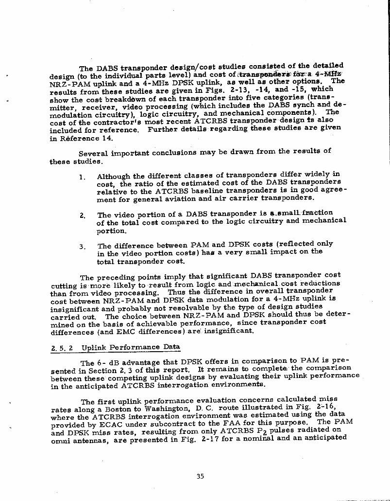
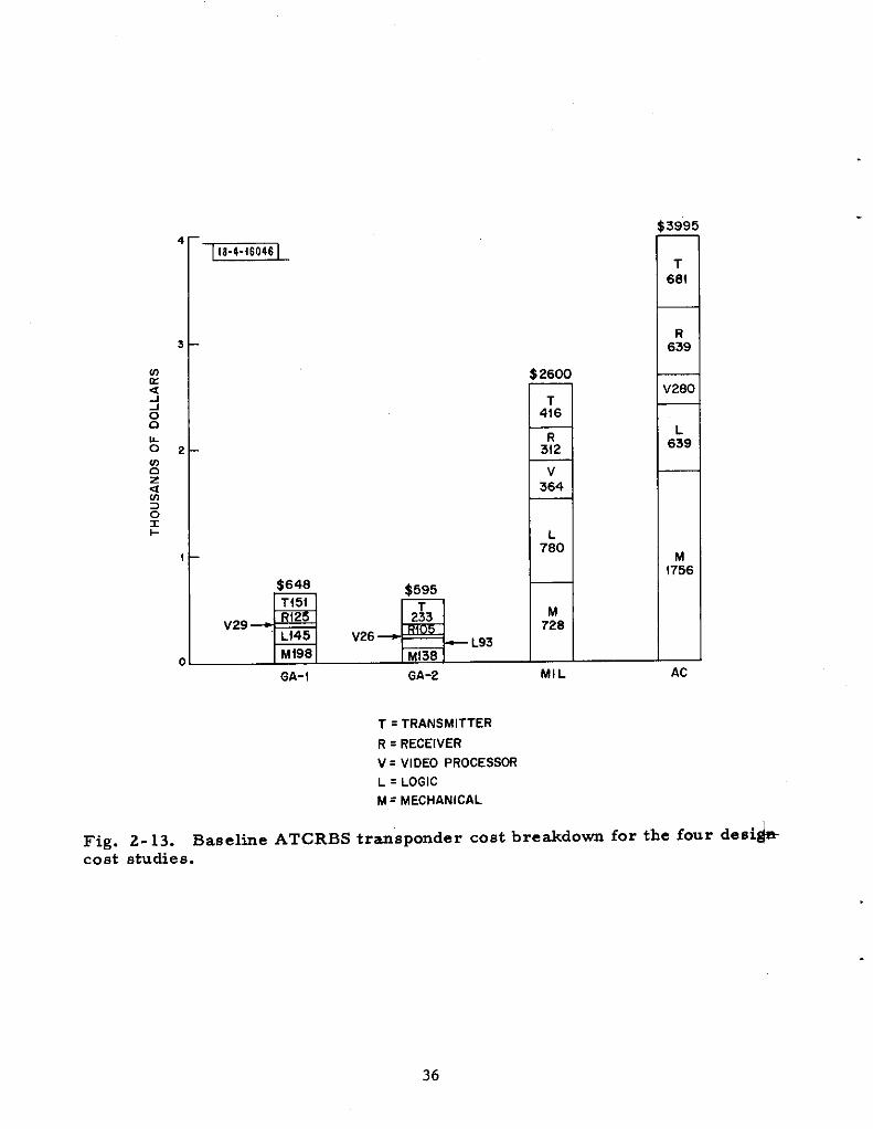
fie DABS transponder design/cost studies consisted of tie detafleddesign (to the individual parts level) and coet of i~~~ti~ --a 4-M=NRZ - PAM uplink and a 4-~z DPSK uplink, as well as other options.. Theresuits from these studies are given in Figs. 2-13, -14, and -15$ whichshow the cast break~wn of each transponder into five categories (trans -mitter, receiver, video processing (wMch includes the DABS synch an~~ -modulation circuitry ), logic circuitry, and mechanical components).cost of the contractors most recent A.TCRBS transponder design !s alsoincluded for reference. Further de~ils regarding fie~e stidies are givenin Reference 14.
Several important conclusions may be drawn from the results ofthese stidiee.
1. Mthough the different classes of transponders differ widely incost, the ratio of the estimated cost of the DABS transpondersrelative to the ATCRBS baseline transponders is in good agree-ment for general aviation and air carrier transponders.
2. me video portion of a DABS transponder is ~.smallf=ctionof the total co et compared to the logic circuitry and mechanicalportion.
3. The difference between PAM and DPSK costs (reflected odyin the video portion costs) has a very small impact on thetotal transponder cost.
me preceding points imply that significant DABS transponder costcutting is more likely to resuM from Iagic and me”c~nical .mst refictionsthan from video processing. Thus the difference in overall transpondercost between NRZ - PAM and DPSK data modulation for a 4-MHz uplink isinsignificant and probably not resolvable by the type of design studiescarried out. The choice between NRZ - PAM and DPSK shouid thus be deter-mined on the basis of achievable pe rfOrmance, s hce transpOnde r costdifferences (and EMC differences) are”. insignificant.
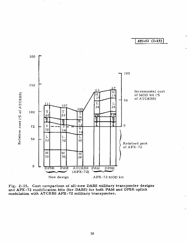
2.5. 2 Uplink Performance Data
The 6- dB advantage fiat DPSK offers in comparison to PAM is pre-sented in Section 2.3 of this report. It remains h completa the comparisonbetween thes e competing uplink designs by evaluating their uplink performancein the anticipated A.TCRBS interrogation environ-nti.
me first uplink performance evaluation concerns calcdated missrates along a Boston to Washington, D, C. route illustrated in Fig. 2-16,where the ATCRBS interrogaKlon environment was estimated using the dataprovided by ECAC under subcontract to the FA.A for this purpose. The PAMand DPSK mies rates, resuittig from only ATCRBS P2 pulses radiated Onomni antems, are presented in Fig. 2-17 for a nominal and an anticipated
35
260(
416
3:2
7364
7:0
$648
*GA-1 GA-2
M728
—MIL
3995
T664
R639
V280
L639
M!756
AC
T = TRANSMITTER
R = RECEIVER
v = VIDEO PROCESSOR
L = LOGIC
M = MECHANICAL
Fig. 2-13. Baseltie ATCRBStrmsponder cost bre~dom for the four deslhcost studies.
I

ATC-52 (2-14) 1
200 7
150
100
50
0 [ATCRBSPAM D
178
182,.. — m
MM M70 70
100
L4“4 26 46
VL ~ y :5 z / / u(u
R L18 16 ;9 v
% v 33
8 T $8 28 R K39
r 16 14 :4!6 T T T
17 ,15 15SK ATCRBS PAM D=K ATCRBS PAM DPSK
/GA-1 GA-2 AL
Fig. 2-14. Cost comparison of DABS trmsponder deeigns for both PAMDPSK uplink modulation with ATCRBS trmsponders for three studies.
200
150
100
72
50
0
‘~ (APX-72) ‘
63
M 1515 , —
L L24 24
~ “ ‘{
1
Tq
iM DPSK
I ATC-52 (2-15)
100
Incremental costof MOD kit (~.
50 of ATCRBS)
o
I
Retained partOf APX-72
New de sign APX-72 MOD kit
Fig. 2-15. Cost comparison of all-new DABS filitary tr~sponder designsmd APX -72 modification kits (for DABS) for both PAM and DPSK upltikmodulation with ATCRBS APX-72 military transponder.

.
Fig. 2-16. Path along which DABS uplink miss rates were calculated forPAM md D PSK uplink modulation.
0.4 ~
NOMINAL ENVIRONMENT
1
0.4 1 I IMAXIMUM ENVIRONMENT
Y )
0,2
<
o~o
6 6 6 6 6
ABOSTON
A A ANEW YORK PHILADELPHIA WASHINGTON
AIRCRAFT LOCATION
SIGNAL LEVEL =-70dBm MATCHED FILTER DEMODULATORS
SNR = 20dB-OPSK, 26dB-PAM PAM THRESHOLD = -4dBALTITUDE = 10,000ft r = o.8ps6c
CHIP OURATION = 0.25~6EC“= looblts
Fig. 2-17. Calculated uplink miss rates for PAM ad DPSK modulation b~ ATCRBS P2 pulse environment prodded by EC.AC.
1

maximum A.TCRBS interrogation environment. These calcubtions weredone for received signal levels at the -70 dBm transponder i. e. , very nearthreshold, where the difference between PAM and D=K is very distkct.PAM and DPSK miss rates, as a function of received sigml level at thetransponder, are presented in Fig. 2-18 for a transponder located overNew York City. The results indicate that the performance advantage ofDPSK moddation translates effectively h a significantly lower ~ss r-at10W signal levels or, viewed from another aspect, DmK pr~vides a largerfade margin down to a fixed uplink miss rate. F~r*er de~tis On the cal-culated uplink performance are in Ref. 15.
A further verification of u~k performance was provided by a seriekof flight tests in which DABS upltik miss rates were directly measured whileflying along a Boston to Baltimore path ~Ref. 16]. These measurementswere made by interrogating a DABS test set capable of processkg both NRZ -PAM and DPSK interrogations. me interrogator was on board the aircraft,and its signals were coupled into the cable connecting a standard beaconantenna to the test set so that the test set could be interrogated with a pre-cisely controlled signal while also receiving the ATCRBS interrogations fromthe antenna.
The test set calibration curves are illustrated in Fig. 2-19 fOr bofiPAM and DPSK, verifying a clear 5 -dB performance margin between thecompeting modulation systems realized by the demoddators of the test set.h order to rationalize the miss rate measurements, the ATCRBS inter-rogation environment was moniti red s imdtaneously while interrogating thetest set and measuring miss rates. A reference signal level was establishedco rrespondtig to the signal level, resulting in a 50~. miss rate of the DPSKdemodtiatu r. The interrogation counts and pulse. comts fa’r:si~als exceed-tig this reference level were also recorded in addition to miss rates. Thusit is possible to bowd the expected miss rates in terms of the measured.A TCRBS interrogation environment, A sample plot of measured miss ratev~ time is presented in Fig. Z- 20, Which also includes measured Modes Aand C interrogation rates, SLS rates, and total video pdse counts of signalsexceeding the’ reference level.
Although the measured ATCRBS environment differs somewkt fromthe predictions provided by ECAC, the measured miss rates are quite closeto those calculated for tie ECAC environment. PAM miss rates weremeasured at an interrogation signal level 5 dB stronger than that of D~K(bringing the reference signal level for interrogation comts to the 5 O% missrate point on the PAM demodulation characteristic [Fig. 2- 19]) and *eY wereessentially the same as DPSK miss rates with this 5 -dB power advantage.
The performance dab support the conclusion that the theoretical ad-vantage of DPSK over PAM is realizable in real channel operating conditionsas a significantly larger fade margin or a significantly lower miss rate atlow signal levels. Since there is an insignificant transponder cost incrementassociated with DPSK, its performance advantage should be utilized. Forthese reasons, DPSK was selected for the DABS uplink moddatilon.
41
0.2
~&a 0,1
0
0.3
0.2
~
ga
0.1
0
I I
NOMINAL ENVIRONMENT ~I
*
OPSKPAM
I
4 MAXIMUM ENVIRONMENT
b
-80 -70 -60RECEIVED
LOCATION - NEW YORKALTITUOE = 10,000 ftNOISE LEVEL = -90dBm
SIGNAL POWER (dEm]
MATCHEO FILTER DEMODULATORSPAM THRESHOLO = -4dBr = O.B ~SeC
CHIP OURATION = O. 25#seC“ = loO bits
Fig. 2-18. Calculated upltik miss rates for PAM and DPSK for transponder -located over New York City in an ATCRBS P2 environment.
42
.
1.0
0 1 I T I 1 1“16 14 12 10 a 6 4 2 0
Fig. 2-19. Test demodulationWeb .VS SIR.
calibration curves for PAM -d DPSK miss
43
I, I I I 1 I 1 1 1 1 1 1
10 = TOTAL PULSES
10x= M00EA8C
. = SLS
1 I I I I I I I I I I I1335 40 45 50 53 1400 5 10, 15 20 25 30
I00 D A;D
(wOOosTOwN,OEL.) (YARDLEy, PA.)
Fig. 2-20. Measured uplink missATCRBS mode snd pulse counts).
Li k
(NYC)
FLIGHT TIME
rates vs time for DPSK (with measured

2. 5.3 Summary of DPSK Uplink Perfortince
Having reviewed the basic reasons for the selection of the DABSuplink signal format, this section provides e~ra data for reference concern-ing the DABS DPSK uplink performance. The performance Qf the parity checkcode was calculated based on models of error mechanisms causedby RFI.The se calculations have been verified by kboratory measurements made ona DABS DPSK test transponder. Figure 2-21 indicates measured ~detectedmessage error rates for fixed DABS signal and interfering pulse levels[Ref. 17]. The measurements indicate that the burst er,ror characterizationused in the calculations was adequate. The measured mdete cted mes sageerror rat , conditional on an interfering signal being present, is of the order
?ofl inl O, the initial DABS performance goal. The multipath sensitivity ofthe DABS uplink was also measured h the Laboratory using a DABS DPSKtest transponder and a mu3tipath s tiulator [Ref. 18]. The results are P*vialed in Fig. 2-22 and illustrate satisfactory agreement with *eoreticalpredictions.
A critical aspect of the uplink design is the reliability of the suppres-sion preamble. The specification of the reliability of the suppression cir-cuitry of ATCRBS transponders is looser near the minimum triggertig level(MTL) of a transponder than the mode triggertig circuitry. This effect isillustrated in Fig. 2+23 which shows measured ATCRBS transponder replyrates to DABS interrogations (indicattig faflure of intentional suppressionpreamble ) [Ref. 7]. The DABS interrogation signal level was nried overthe dynamic range of the ATCRBS transponders. Figure 2-23 *dicates themaximum reply rates: e.bserved for:two cases:
1. me suppression preamble (PI P2) ampli~de equal to theda~ block amplitude
2. The (PI P2) amplitide 3 dB greater than the data blockamplitude
The measured’ dab indicate the maximum reply rates observed are quitehigh, but the figure does not indicate that the reply rates are limited to a verynarrow range of signal levels. Thus, the to~l number of replies. likely to becontributed by ATCRBS transponders, which fail to be suppressed by a DABSinterrogation, is small (most hterrogation.. levels: received a~e .oatai,de-the::narrow triggering range). U observed ATCRBStransponder triggering ratesare judged unacceptably high, the data indicate that increasing the amplitudeof the suppression preamble by 3 dB relative to the dab block wodd reducequite signtilcantly the peak triggertig rates observed (and, hence, tie totalnumber of replies contributed to the charnel). It sho~d be pointed Out thatthis approach complicates the sensor transmitter by requiring switetig bfpower levels durtig an hterrogatior, consequently a clear justification ofthe necessity for this change in signal formats wodd be needed.
~
io-’ –UNDETECTED ERROR PROBABILITY, Pe
MESSAGE LENGTH 96 BITSINTERFERENCE MODE 1: P2 AT PRF 32.3k Hz
INTERFERENCE MODE 2: Pl,P2ATPRF30.3kHz
~w ‘sNR=’6dB +
)
10-8 —
(a)
{o-g I I I I 1 I io -i -2 -3 -4 -5 -6 -7 -8 ‘g -f(
SIGNAL-TO-INTERFERENCE RATIO (dB)
Fig. 2-21(a). Laboratory measurements of undetected message errorprobabilities (DPSK) for simulated garbling by an .ATCRBS P2 pulse md a
‘1’P2 mode.

~w
40-8rUNDETECTED ERROR PROBABILITY, Pe
MESSAGE LENGTH 96 BITS
INTERFERENCE MODE l:P1, P2, P3 MODE 3jA PRF 25.6k Hz
INTERFERENCE MODE 2:P1, P2,P3 MODE 3/APRF25.6kHz
SNR=16dB
(b)
47
SIGNAL -TO-INTERFERENCE RATIO (dB)
Fig. 2-21(b). Laboratory measurement of undetected message errorprobabilities (DPSK) for simulated garbling by two ATCRBS titerrogations,each with PI, P2, P present.
3
. . ,,..—,

L“
{0-6 -
! 0-7 —
UNDETECTED ERROR PROBABILITY, Pe
MESSAGE LENGTH 96 BITS
INTERFERENCE MODE I : P1, P2, P3 MODE 31A PRF25.6k Hz
INTERFERENCE MODE 2: P1,P2 MODE 3ZAPRF30.3kHz
SNR =16dB
(c)
10-a I I I I I I I I I I1 0 -f -2 -3 -4 -5 -6 ‘? ‘8 ‘g “
SIGNAL -TO -INTERFERENCE RATIO (dB)
Fig. 2-21(c). Laboratory measurement ofmdetected message errorprobabilities (DPSK) for simulated garbling bytwo ATCRBS mode 31Ainterrogations (one two-pulse ad one with all three pulses present).
I48
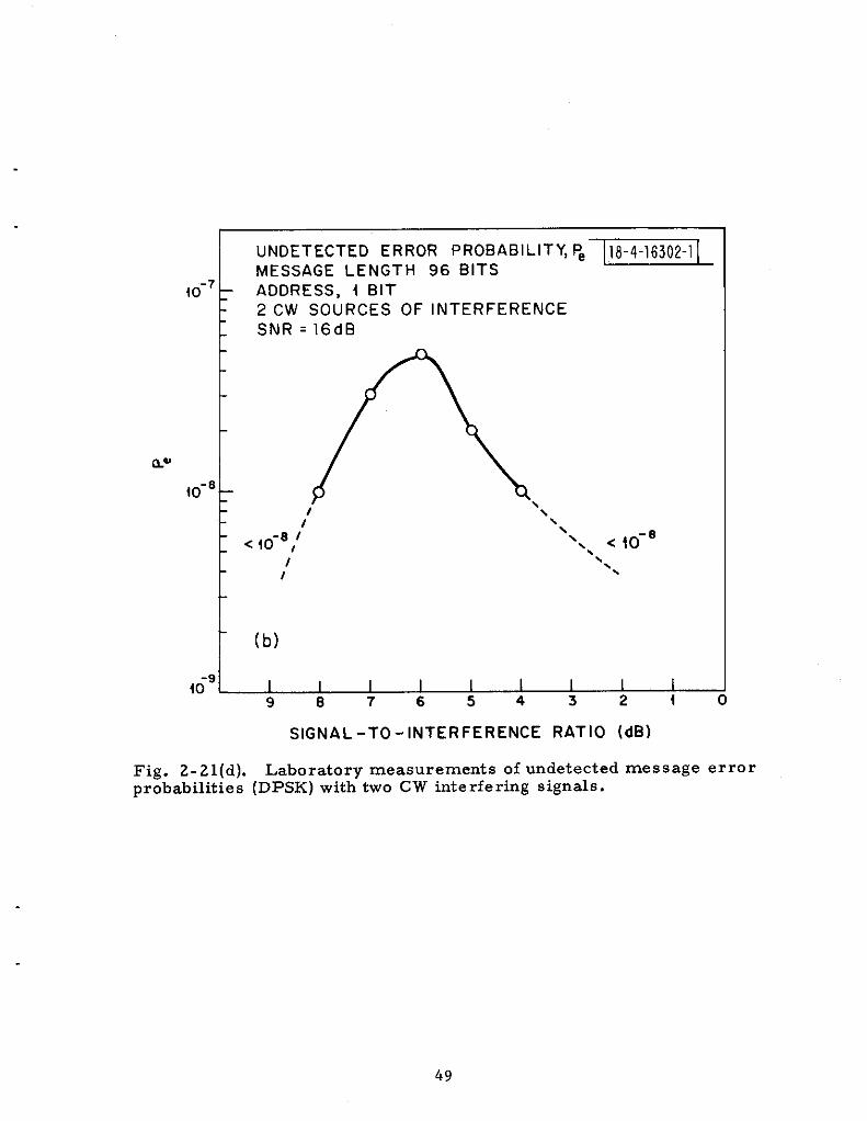
1UNDETECTED ERROR PROBABILITY, ~~MESSAGE LENGTH 96 BITS
{0-7 ADDRESS, i BIT2CW SOURCES OF INTERFERENCESNR=16d B
46g~9 8 7 65432i C
SIGNAL-TO-INTERFERENCE RATIO (dB)
Fig. 2-21(d). Laboratory measurements of undetected message errorprobabilities (DPSK) with two CW titerfering signals.
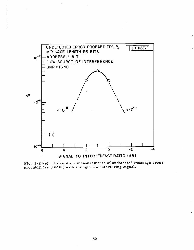
UN DETECTED ERROR PROBABILITY, Pe~
MESSAGE LENGTH 96 BITS-7
40
E
ADDRESS, 1 BIT
lCW SOURCE OF INTERFERENCE
SNR=16d B
A/ \‘\\
40-8
I/ \
-8/’
\<10 \<io-8
t(a)
,o-g~6 4 2 0 -2 -4
-.SIGNAL TO INTERFERENCE RATIO (dB)
Fig. 2-21(e). Laboratory measurements of undetected message errorprobabilities (DPSK) with a stigle CW interfering signal.
50
40-7
P@
40-’
40-’
E I I I I I I~
UNDETECTED MESSAGE ERROR PROBABILITY, Pm
1MULTIPATH SINGLE-DELAY INTERFERENCE -S\N = 16dB
6-M Hz 5-SECTION FILTER
96-BIT MESSAGE
SAMPLE TlME=f20nsec
1
INTERFERENCE-TO-SIGNAL RATIO (dB)
Fig. 2-22. Laboratory measurements of undetected message errorprobabilities in simulate’d multipath.
51
I
ATC-52 (2-23)
h—{PI and P2) / Message = 3 dB
-- Results with (Pl and P2) / Message = 3 dB
No replies
--,-
-- :L-, ?.7: - r--:
-.-; , :-q. !o
*0.1 0.2 0.3 0.4
Maximum reply ratesper interrogation
Fig. 2-23. Percentage of transponders reply vs maximum reply rate perinterrogation for DABS preamble amplitude equal to message amplitnde, and3 dB greater than message amplitude.
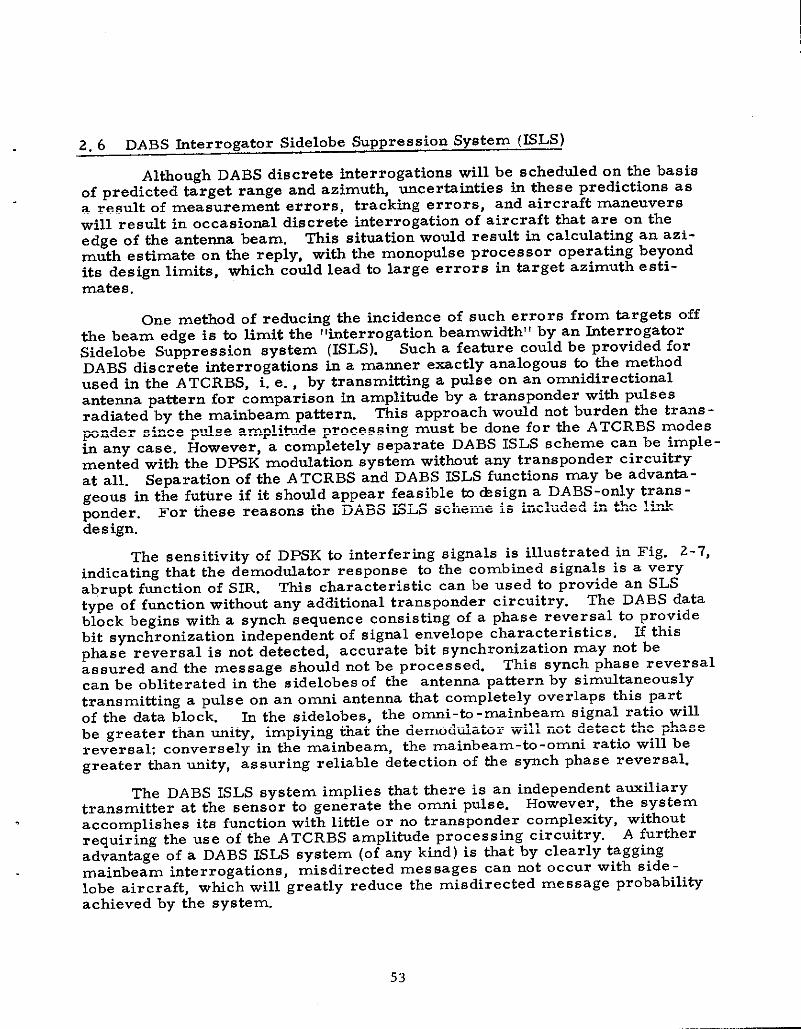
2.6 DABS hterrogator Sidelobe Suppression System (BLS)
Although DABS discrete interrogations will be schedded on the basisof predicted target range and azimuth, uncerbinties in these predictions asa result Of measurement errors, tracking errors, and aircraft maneuverswill result in occasio=l discrete interrogation of aircraft that are on theedge of me antenna beam. This sit~tion wodd result in calculating an azi-muth estimate on the reply, with the monopuls e processor operating beyondits design limits, which codd lead to large errors in tirget azimuth esti-mates.
One method of reducing the incidence of such errors from targets offthe beam edge is h limit the “interrogation beamwidth” by an kte rrogatorSidelobe Suppression system (ISLS). Such a featire could be provided forDABS discrete titerrogations in a manner exactly analogous to the methOdused in the ATCRBS, i. e. , by transmitting a pulse on an omnidirectionalantenna pattern for comparison in amplitude by a transponder with pulsesradiated by the mainbeam pattern. This approach wodd not burden the trans -ponder since pdse amplitide processing must be done for the ATCRBS modesin anY case. However, a completely separate DABS ISLS s theme can be imple -mented with the DPSK moddation system without any transponder circuitryat all. Separation of the ATCRBS and DABS KLS functions may be advanta -geous in the future if it shotid appear feasible to *sign a DABS-only trans -ponder. For these reasons the DABS ISLS scheme is included in the linkdes ign.
The sensitivity of DPSK to interfering signals is illustrated in Fig. 2-7,indicating that the demodulator response to the combined signals is a veryabrupt function of Sm. This characteristic can be used to provide an SLStype of function without any additional transponder circuitry. The DABS datablock begins with a synch sequence consisting of a phase reversal to providebit synchronization independent of signal envelope characteristics. H thisphase reversal is not detected, accurate bit synchronization may not beassured and the message should not be processed. This synch phase reversalcan be obliterated in the sidelobes of the antenna pattern by simultaneouslytransmitting a pulse on an ornni antenna that completely overlaps this partof the data block. ~ the sidelobes, the omni-tn -mainbeam signal ratio willbe greater than unity, implying that the demoddator will not detect the phasereversal; conversely in *e mainbeam, the mainbeam-to-omni ratio will begreater Man unity, assuring reliable detection of the synch phase reversal.
The DABS ISLS system implies that there is an independent aoxiliarytransmitter at the sensor to generate tie Omni pulse. HOwever, the systemaccomplishes its function with little or no transponder complexity, withoutrequiring the use of the A TCRBS amplitude processing circuitry. A furtheradvantage of a DABS KLS system (of any kind) is that by clearly taggingmainbeam interrogations, misdirected mes sages can not occur with side -lobe aircraft, which will greatly reduce the misdirected message probabilityachieved by the system.
53

2.7 Target Acquisition
Efficient handling of targets by discrete address interrogations re-quires knowledge of the discrete address of the target and predictions ofits range and azimuth. In anautomated ATC system, POP-UP targets anddropped targets should be handled automatically, i.e., a special acquisi -tion mode should be provided to whicha DABS transponder would reply withits discrete address and be located at the same time. TO periodically searcha stinsorrs coverage volume (for pop-up or dropped DABS targets) would re -quire the use of such an acquisition or ,,all -call,, mode. In this regard, the
DABS all -call mode is analogous to the operation of the standard ATCRBSsensor in which periodic interrogations are transmitted and followed by alistening interval. Since a DABS sensor must provide position and identityinformation on ATCRBS transponders, more channel time would remain freeif the DABS all-call listening period were shared with that of the ATCRBSmodes. In order to share listening periods, the DABS all -call mode shouldbe transmitted fairly close in time to an ATCRBS interrogation. Two alter-natives are:
1. DABS all -call preceding the ATCRBS mode
2. ATCRBS mode preceding the DABS all -call.
Consider the second alternative first. The quandry in which thisarrangement places a DABS transponder is whether or not to reply to theearlier ATCRBS interrogation. TWO types of replies are clearly redundant.However, if the DABS transponder is to recognize that a DABS all -callfollows the ATCRBS mode, it must do so quickly, i.e. , in the 3 ~sec betieenthe pulse P3 of the interrogation and the F Pulse Of the ‘eP1y. ‘his observa -tion implies that a combined AT CRBS/DA~ all - call mode could be definedso that ATCRBS transponders process only the ATCRBS part of the mode,and DABS transponders do the same but also look for a“n indication pulsedesignating the mode as an all-call. Detecting such an indicator pulse wouldthen result in the DABS transponder inhibiting its ATCRBS reply and trans -mitting a DABS all-call reply containing its 24-bit discrete address.
This combined ATCRBS/DABS all-call mode has been realized by
appending ~ fourth pulse af~r the P3 pulse tO standard ATCRBS mOdes 3/Aand C as illustrated in Fig. 2-24. Measurements were made during fieldtests on ATCRBS transponders to verify that the P4 pulse had nO significanteffect on them [Ref. 7]. A very slight difference ~ the response thresholdsfor the standard ATCRBS mode A and the ATCRBS/DABS all-call (mode Awith P4’added) is indicated in Fig. 2-25. The data lead one to believe thatATCRBS transponders that are operating normally within specifications willnot be signif~cantly affected by the P4 pulse.
’54:
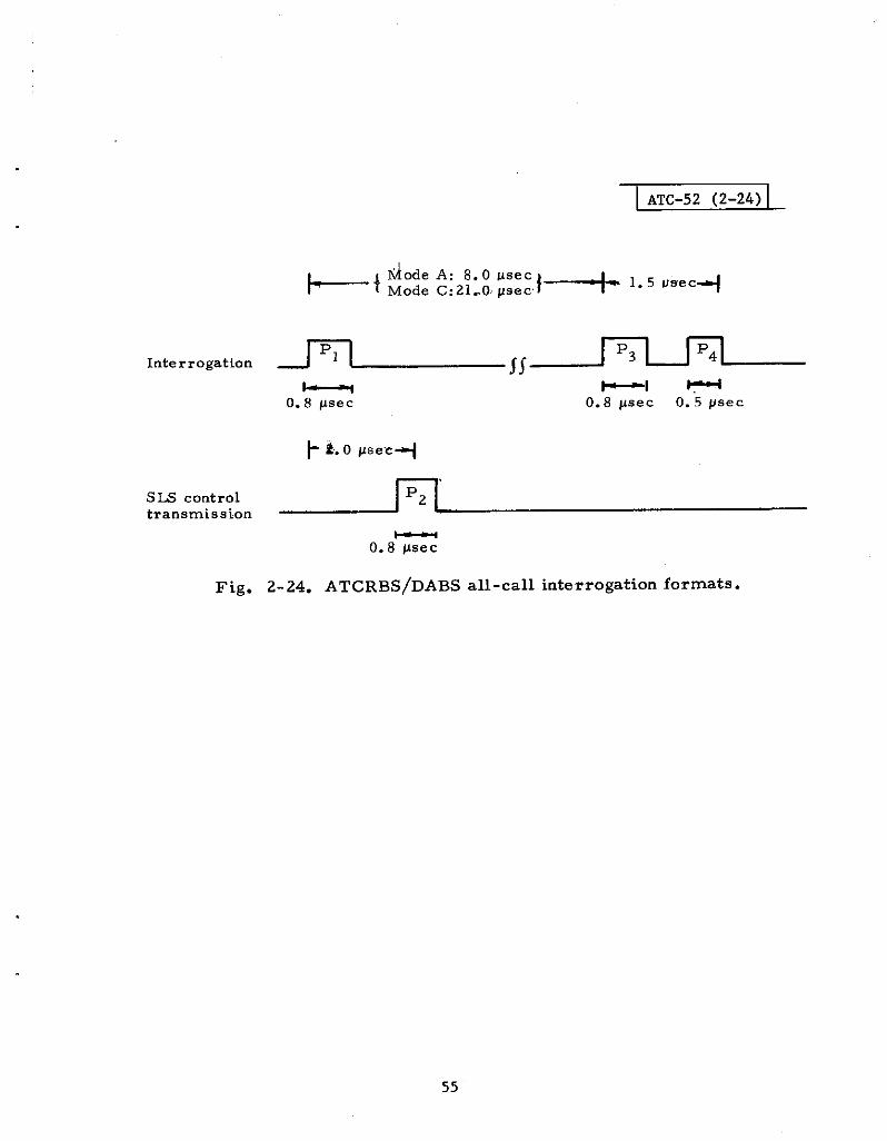
+’
Interrogation m
ATC-52 (2-24)
~ode A: 8.0 use.Mode C:ZI.O ps~c}-~ 1.5 u~ec+
*I *O. 8 psec 0.8 psec O. 5 psec
S= controltransmission
—0.8 psec
55
Fig. 2-24. ATCRBS/DABS all-call interrogation formats.
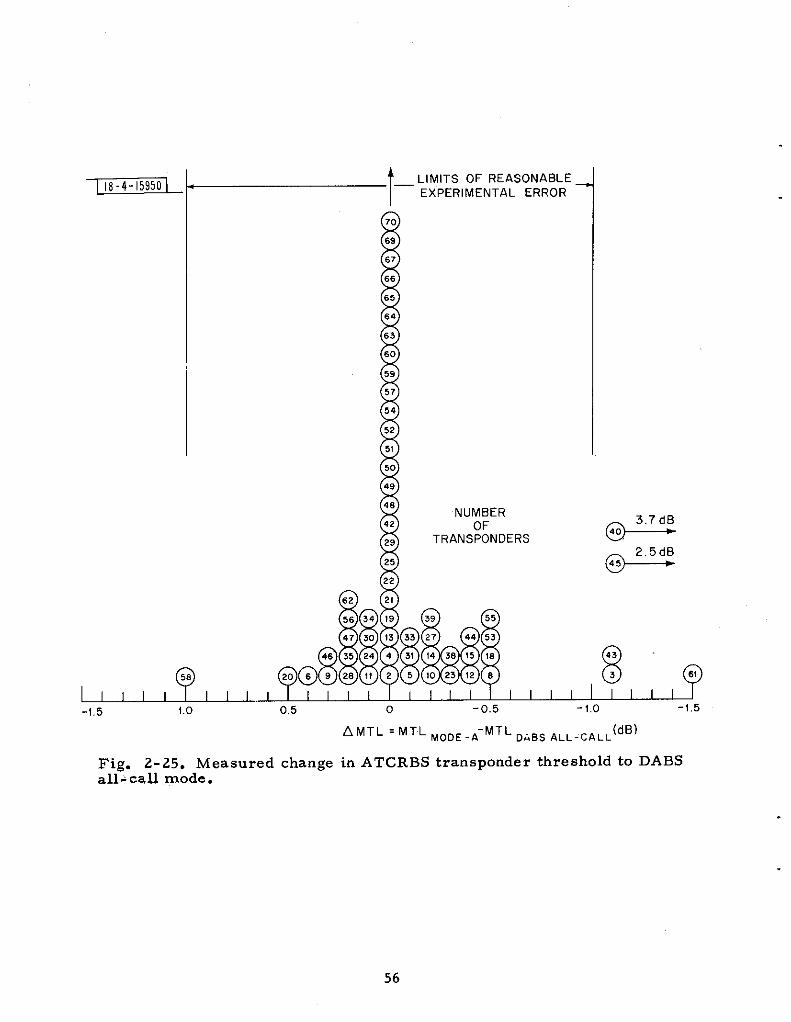
?0
69’
67
6 6
6 5
6 4
6 3
6 0
59
5 ?
5 4
5 2
5 I
50
4 9
4 8
4 2
2 9
2 5
2 2
, ,,[~ ~~~~,,111,,,11
62 2 I
56 34 ! 9 39 55
47 30 I3 33 27 44 53
58q@8::: ~~~~~~
I I I I I I I-1,5 1.0 0.5 0 -0.5 -1,0 -1.5
NUMBEROF
TRANSPONDERS
,843
3
AMTL =MTL ~oDE.A-MTL ~&B~ ~LL_cALL(dB)
56
@
Fig. 2-25. Measured change in ATCRBS transponder threshold to DABSall+ caU mode.
Consider next the DABS all-call mode preceding the A TCRBS mode.The DABS transponder would respond to the all-call mode and probablywould not see the following A TCRBS mode occurring during its reply or itsdead time after replying. An ATCRBS transponder, conversely, must nOtrePly to the DABS mode, and ideally, the DABS all-call mode shodd bellinvi~iblell ~ ATCRBS transponders. However, as the bench testing pro-gram has indicated, such invisible formats are not feasible. me next bestalternative is a DABS mode that intentionally suppresses ATCRBS transpon-ders and elicits all-call replies from DABS transponders. Such a separateDABS -ody all-call mode may be usefti in that it would allow some flexibilityin scheduling DABS all-call replies relative to A TCRBS replies, which co~dbe used in mitigating synchronous garble betieen A TCRBS and DABS all-calltargets. ~is flexibility, however, comes at a price of less overlap Of thelistening intervals as a resdt of the need to wait at least 45 ~sec for theATCRBS transponders to recover from the suppression caused by the DABSmode.
Both of the above approaches to the acquisition of DABS targets havebeen included in the DABS link design. The standard mode is the combinedA TCRBS/DABS all-call mode, which appends a P4 pulse after a standardA TCRBS mode 3/A or C interrogation and shares the full listening intervalof both types of replies. The DABS-only all-call mode consists of a standardDABS DPSK interrogation (preceded by a suppression preamble) with an. all-zero address that will elicit an all-call reply from DABS transponders ~.’The added complexity of checking for an all-zerO address, in addition”tO thestandard address checking, dOes nOt add signirlcant cOst tO the transponder.The DABS - only all - call mode allows some scheduling flexibility betieenATCRBS and DABS-all-call replies, if it ever appears to be of value, and italso provides a means of acquiring targets independent of ATCRBS modeprocessing circuitry, which may prove useful at some future’ data.
*The data field of the DABS-only all-call interrogation consists of all-ones,
to help distinguish this signal from CW or a 10ng, unrnoddated pulse.
’57

3.0 DOWNLINK DESIGN
3.1 Design Constraints and Options
The basic functions of the DABS downlink are to:
1. Provide target range and azimuth estimates for DABSsurveillance,
2. Extract downlink data from replies (target identity, altitude,pilot acknowledgments, etc, ),
3. Support air -to -ground data link capability for noncriticalmessages.
The issues of transponder cost, EMC, and link performance are next dis -cussed in this section with respect to the use of the ATCRBS reply frequencyof 1090 -z for the DABS downlink.
3. 1.1 Transponder Cost
The transponder r cost data of Section 2.5 indicate that the transmitterportion of an A TCRBS transponder is significantly more cosfly than thevideo process ing circuitry<<. This is especially apparent in the general avia -tion class of transponders. This is true h spite of the fact that transmittersfor nonmilitary ATCRBS transponders are very simple pulsed oscillatorcircuits that generate incoherent, on- off keyed pulses suitable for PAM mod -.ulation formats. Although some military transponders have used solid statetransmitters,’ the cost of such transmitters at the power levels required forthe ATCRBS is not now cost competitive with the triode/cavity oscillatorsused in general aviation transponder rs. Cost projections of solid state trans -mitters are uncertain enough to avoid basing a DABS design on reasonablecost devices not available at this time.
Thus cost considerations constrained DABS reply format options (atleast initially) to those that could avoid the necessity of a more sophisticatedtransmitter than that now employed by ATCRBS general aviation transpon-ders. Even a second such simple transmitter required by DABS (at anotherfrequency) wodd have a noticeable impact on transponder cost. For these
58
*This is clearly true in all except the military transponder, wherein video
processing circuitry is more complex as a result of Mode 4 processingfunctions. Civil transponders do not process this mode.

--- . . . . . .
.
reasons, the DABS downlinK signal aesign effort began by investigating mod-ulation formats that could be generated by the low cost ATCRBS (generalaviation) transponder r transmitted rs. This implied that modulation formatsbased on on-off-keyed, incoherent PAM pulses were to be investigateduntil and unless it was discovered that *ey were clearly inadequate fr.m aperformance or EMC viewpoint.
3. 1.2 EMC Issues (A TCRBS)
DABS replies can have two effects on the ATCRBS downlink opera-tion that deserve investigation. They can result in ( 1) lost ATGRBS rePliesas a result of garble by a DABS reply, and (2) triggering ATCRBS replYdetection circuits. The greater information content of a DABS reply im-plies a longer duration than that of an ATCRBS reply: therefore detectionand correct decoding of an ATCRBS reply (by existing equipment), garbledby a DABS reply, is very unlikely unless the amplitude of the ATCRBS re -ply is much greater than that of the DABS reply. Mitigation of this effectwill therefore depend upon reducing the frequency of occurrence of DABSfruit garbles.
A DABS reply input to an ATCRBS bracket detector is likely to re -suit in repeated triggering of the circuit for the entire duratiOn of the DABSreply data block. Such repeated and closely spaced bracket detections maycofiuse garble detection/phantom elimination logic in ATCRBS reply pro -ce ssors and may also cause undesirable artifacts on video displays. Themain preventative measure against this effect is a defruiter, which wouldrequire near synchronous DABS replies on at least two successive scans toallow processing of a DABS reply data block by bracket detection circuits.Although most ATCRBS reply processors incorporate a defruiter, all equip-ment does not incorporate a defruiter (the Common Digitizer employed atsome FAA en route radars being the most notable example). Consequently)this effect does deserve further consideration. The effects of DABS repliesto discrete address interrogations and all-calls will be dis~us sed separatelywith respect to the ATCRBS downltik operation.
Discrete AddrAss (Scheduled) Replies
DABS discrete reply fruit reply rates will be much lower than that ofcurrent ATCRBS fruit rates because ( 1) only a small number (typically twoor three) sensors will discretely interrogate each DABS aircraft, and (2) theaverage number of discrete interrogations per scan will be much less thanthat of the ATCRBS (an average of less than two per target per scan, com-pared to antaverage of 18 for an ARTS sensor). An additonal factor that willmitigate the effects of DABS discrete replies is the asynchrOnOus na~re ofthe DABS scheduling of discrete interrogations, which will tend to garble aninsufficient number of ATCRBS replies per scan (for a given target) to affecttirget recognition (by human operator) or declaration (by automatic detec -tibri”iircfiits). ATCRBS reply processors incorporating a defruiter will nbt
59
be affected by DABS discrete replies. Moreover, as a result of this aspect,the very low DABS discrete reply rate, together with its highly asynchronousnature, will render the effects of lost ATCRBS replies insignificant even inprocessors without defruiters. However, the effects of occasional DABSreplies that do get processed by conventional circuitry should be investigatedfurther to determine if special measures must be implemented to preventpossible confusion of operators or automatic processors.
All- Call Replies
A DABS sensor acquiring new DABS targets by transmitting the com -bined ATCRBS/DABS all-call mode will be faced with occasional synchro -nous garble between an ATCRBS target and a nearby DABS target respond-ing to the all-calls , and will also generate DABS fruit, which could affectnearby DABS and ATCRBS sensors. In the case of synchronous garble ofan ATCRBS target tind a DABS all-call target, if both replies are likely tobe lost most of the time in such “synchronous garble satiations, the longerchannel occupancy of the DABS reply will’ result in a larger garble cell*,and both targets may be lost for an extended ~~riod of time. The conse -quences of such synchronous garbles would be grtiatly mitigated by a veryreliable DABS downlink that would allow rapid acquisition of the DABS tar-get even in the presence of such garble. The DABS target could then bequickly switched to a discrete address mode and locked out to the all-callinterrogations (inhibiting all-call replies by setting a control bit in the dis -crete interrogations to that aircraft). It would therefOre be useful tO designhto the DABS reply signal format a degree of immunity to garble fromATCRBS replies, which would serve to aid rapid DABS target acquisitionand minimize the loss of ATCRBS targets to synchronous garble (with DABSall-calls).
Surveillance of ATCRBS targets by .i DABS *ens~r, compared toconventional ATCRBS sensors, will be accomplished using a low PRF. Thus,the low PRF of the combined ATCRBS/DABS all-call mode of a DABS sensorimplies that less fruit will be generated by this mode than by a conventionalATCRBS sensor. Moreover, the all-call mode is transitory, in that aircraftwould normally respond to all-calls for a short time until they could be han-dled using a discrete address mode and locked out to all-call interrogations.For these reasons, DABS all-call fruit is expected to have a very minoreffect on ATCRBS operation. However, the low PRF and the longer DABSreply duration may occasionally result in synchronous garble with a nearbyATCRBS sensor operating at, or approximately at, a multiple of the DABSall-call PRF. Also, since all DABS sensors will operate at approximatelythe same low PRF, DABS all-call fruit from one sensor may garble all-callreplies of another DABS sensor. Although these effects do not appear to beserious, it is difficult (without a fa ir.lv detailed s vstem simulation of a mixed
60
~’tiynchronous garble occurring for larger separations betieen the DABSand ATCRBS target than for two ATCRBS target.

DABS and ATCRBS sensor environment and a combination of DABS- andATCRBS-equipped aircraft) to make a quantitative assessment of tie opera-tion of the combined A TCRBS/DABS all - call mode operation.
Summary of the ATCRBS EMC Issues
The very low DABS fruit rates (from both s chedded and all-callreplies ) will not deprive the ATCRBS system of enough idormation toseriously degrade its performance. However, peculiar A TCRBS replyprocessing equipment responses to DABS replies may result in undesirableeffects, which could necessitate some minor equipment modifications.Experiments shodd be conducted to determine if there is a need for suchmodifications. The DABS all-call replies at a low but regular PRF mayresdt in near synchronous interference with both ATCRBS and DABS sensorsnearby (all - can mode ). Assessment of such effects shotid be done (probablyby a detafled system simdation that incorporates a realistic characterizationof the DABS channel ~gement function, sensor PRF assignments, etc ).
3. 1.3 ECM Issues (TACAN)
Major Effects
Again the major effects on TACAN/DME beacons are loading anddeadtime, and the major effect on TACA.N/D~ interrogations is AGCcaptire.
De gradation Criteria
For interference to TACAN/DME interrogators, the AGC captureeffect may be assessed in terms of the effective average interference power(EAIP). Performance is not noticeably degraded, provided EAIPSMax (EAIP),where Max (EAIP) is an empirically determined tolerance level.
For interference ‘to TACAN/DME beacons, the degradation criterionis kept parametric at this time, with the expectation that loading = deadtime= 5 ~. will be shown to be acceptable in the futire.
EstimatAd Levels of Interference
ECAC has generated estimates of TACAN/DME loading and deadtime(taking into account contributions from an assumed environment of DABS-equipped aircraft) .[Ref. 8]. Typical results are shown in Fig. 3-1. A worstcase is represented with the TACAN/DME beacon located at JFK Airportand with a conservatively high estimate of DABS transponder density. There suits indicate that a 5 ~. loading -deadtime criterion would not be exceededfor any channel separated by at least +3 MHz, Furthermore there is a la~geOFR improvement for greater frequency separations. For reference with
,61

1 I
●Worst case (rein) TACAN/DME signal level
●New York 1982 worst case traffic model
●Location: JFK Airport.
,10
1
100
Fig.
I ATC-52 (3-1) 1
0 5
l“m”
o 5 10 15
AF = Ibeacon receiving frequency - 1090 *“Hz [(wz)
3-1. Effects of DABS dwnlink on TACAN/DME beacons.
62
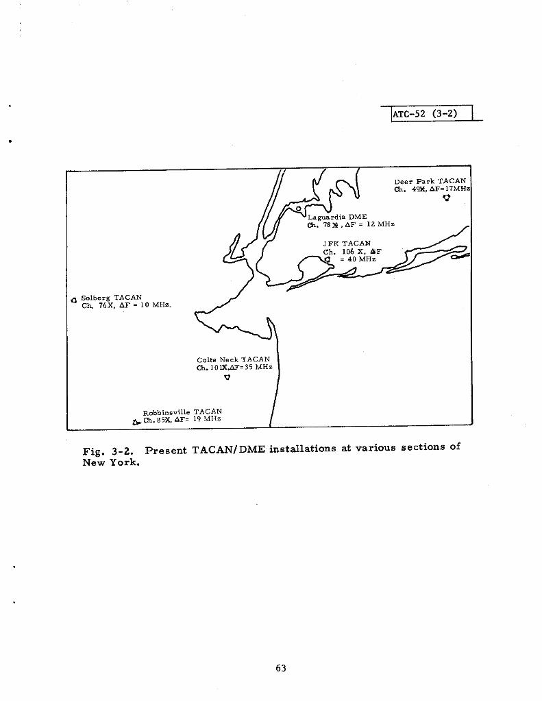
ATC-52 (3-2)
.
Deer Park TACANeh. 4%, AF=17MHz
Lag”ardia DME~. 78x, AF= 12 MHz
> S.lberg TACANCh. 76X, AF= 10MH..
C.lte Neck TACAN~. 10K,~=35 MHz
v
Robbinsville TACAN&~.85X, AF= 19 MHz
Fig. 3-2. Present TACAN/DME installations at various sections ofNew York.
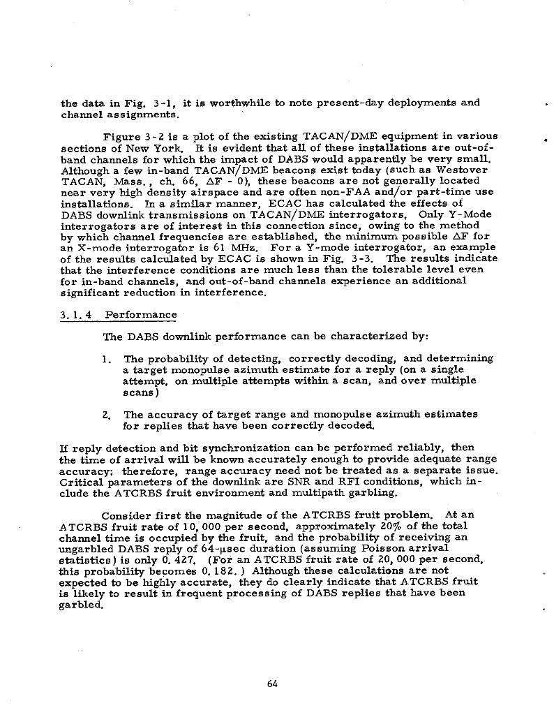
the data in Fig. 3-1, it is worthwhile b note present-day deployments andchanel assignments.
Figure 3-2 is a plot of the exis ttig TACAN/DME equipment in vsrioussections of New York. It is evident that aU of these installations are out-of-band charnels for which the impact of DABS wodd apparently be very small.Although a few in-band TACAN/DME beacons exist tiday (such as WestiverTACAN, ~SS. , ch. 66, AF - O), these beacons are not generally locatednear very high density airspace and are often non-FAA and/or part-time useinstallations. k a similar manner, ECAC has calculated the effects ofDABS dowdink transmissions on TACAN/D~ interrogators. Only Y-Modeinterrogators are of interest in this tonne ction since: owing to the methodby which charnel frequencies are established, the minimum possible AF foran X-mode interrogator is 61 MHz. For a Y-mode interrogator, an exampleof the results calculated by ECAC is shown in Fig. 3-3. The re suits indicatethat the interference conditions are much less than the tolerable level evenfor in-band charnels, and out -of -band channels experience an additional5ignificant reduction in interference.
3. 1.4 Performance
The DABS downlink performance can be characterized by:
1. The probability of detecting, co rrectiy decoding, and determininga target mono pulse azimuth estimate for a reply (on a singleattempt, on mdtiple attempts within a scan, and over mdtiplescans )
2. The accuracy of target range and monopulse azimuth estimatesfor replies that have been correcfly decoded.
E reply detection and bit spchronization can be performed reliably, thenthe time of arrival win be known accurately enough to provide adequate rangeaccurac~ therefore, range accuracy need not be treated as a separate issue.Critical parameters of the dowflink are SNR and RFI conditions, which in-clude the A TCRBS fruit environment and mdtipath garbling.
Consider first the magnitide of the ATCRBS fruit probbm. At anATCRBS fruit rate of 10, 000 per second, approxiwtely 20~. of the totilcharnel time is occupied by the fruit, and the probability of receiving an
~garbled DABS reply of 64-~sec duration (assum~g Poisson arrivalstatistics ) is ody O. 427. (For an A TCRBS fruit rate of 20, 000 per second,this probability becomes O. 182. ) Although these calculations are notexpected to be highly accurate, they do clearly indicate that A.TCRBS fruitis likely to result in frequent processing of DABS replies that have beengarbled.
64
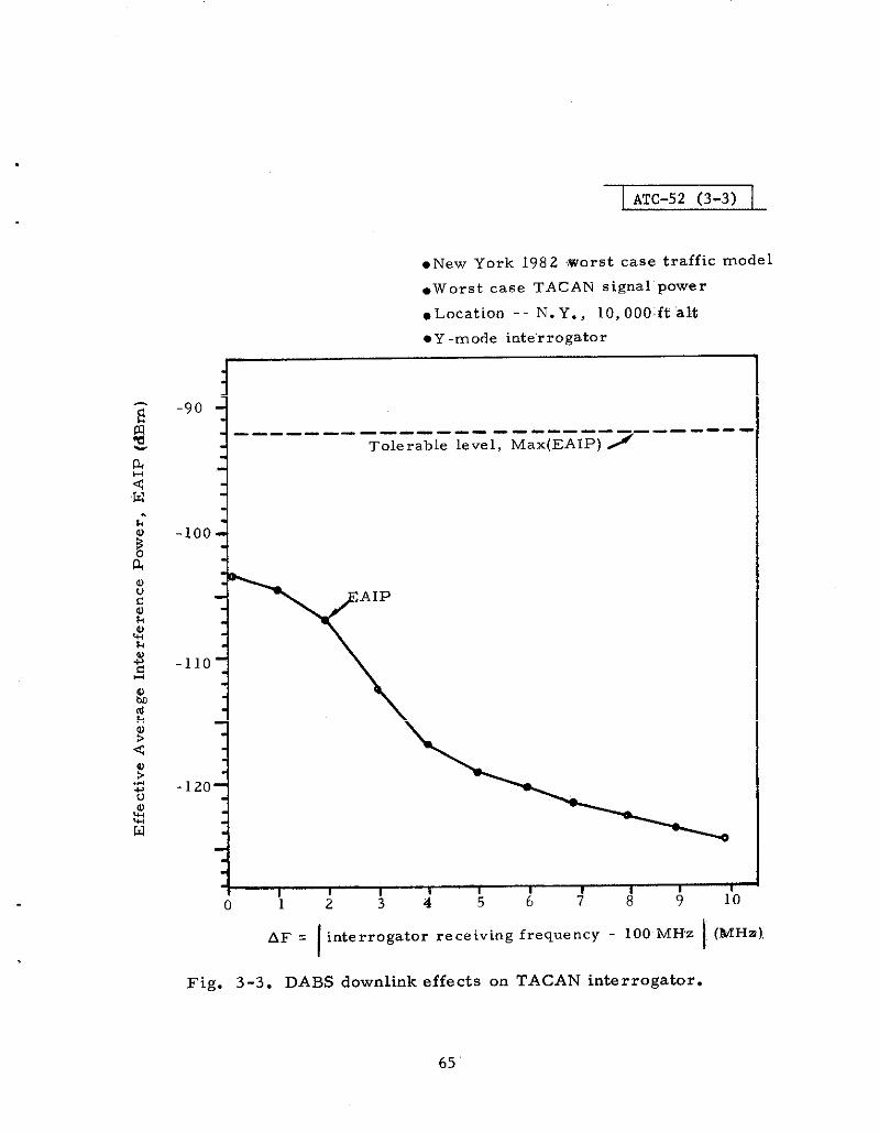
I ATC-52 (3-3)
●New York 1982 ,Worst case traffic model
.Worst case TACAN signal ”power
.Location -- N. Y., 10,000ft “alt
●Y -mode interrogator
-90
i
—--—- —-——- —— --- ---—- -— —-— ----Tolerable level, M.x(EAIP) ~
II 1 I 8 1 I I I I ,
0 1 2 3 4 56 7 8 9 10
65
IAF = interrogator receiving frequency - 100 MHz (MHz),
Fig. 3-3. DABS downlink effects on TACAN interrogator.

M further points shodd be made in assesstig the severity of theATCRBS fruit problem First, ATCRBS fruit iO mt as ~ontrohble a eye-tern parameter as the titirrogation rate because, altiugh ATCRBS se-oroperation is government re~ted, frutt depends on traffic demity as we~,which cotid peak up in localized areas. Second, heavy frtit rates are likelyto correspond to heavy DABS traffic densities where tie DABS s-r caps-city is most likely to be stressed. ~erefore, the D-S dotiti ~signmust seek an efficient link on 1090 ~z in the presence of heavy ATCRBSfruit levels, and a significant degree of immunity to ATCRBS fruit garbltigwU1 be a necessity.
Minimization of DABS channel occupancy implies Me need for afl~design and a processing system that can extract all necessary survei~anceand communication information from Me m~mum number of replies. For&is reason it was necessary to incorporate a monopdse processtig systemto provide azimuth estimation of targets on a single reply. Monopdseazimuth estimation involves the estimation of angle of arrival of an RF s ig -nal relative b the antena bores ight axis, which is then combined with theantenna pointing angle to determine target azimu~ Mono-se systemsare known to be sensitive tu interfertig signals such as ATCRBS fruit garblesand mu3tipath garbles [Ref. 19]. Monopdse processing of garbled DABSreplies complicates the problem, especia~y stice tie monopulse accuracygoal requires averaging the monoptise samples @ken on several individualpu3ses in order to reduce errors caused by noise. A garble senstig tech-nique is necessary for editing the reply pdses to recognize garbled pdses sothat they can be ignored by the monopdse system.
Mdtipath is another possible source of inte rfe ring signals which canlead to significant monopulse errors. The sensitivity of monopulse to interf-ering signals is such that it is. expected that multipath garble will firstresdt in erroneous, monopdse estimates (or no monopdse estimate if a sen -s itive garble sensing technique is:used ) before da@ demoddation is limitedby the interference. Thus mtitipath must be controlled for monoptise towork adequately., and if it is so controlled, it’ is likely that data demodulationwill also work satisfactorily. This implies that multipsth is a problem thatmust be controlled by s ens or antenna design and siting ratier than a modda -tion format that is immune to multipsth garble.
3. 1.5 Downlink Design Philosophy
Transponder transmitter cost will represent a significant portion ofthe overall cost of a transponder; consequently the transmitte~ !cost cons-traints will be more conspicuous in the down3ink design than in the uplink,DABS reply signal formats, which could be generated by present-day, lowcost A TCRBS transponder transmitters (i. e. , signal structure composed ofphase incoherent, on-off keyed pulses ), were thus the primary focus ofinitial design efforts; h addition to these waveform constraints, the perfor -mance considerations discussed in subsection 3. 1.4 established thedesirabili~ of the following DABS reply features.
66

.1. Reply Preamble: MBS reply detection shodd be based on a
special preamble waveform at the start of each reply to avoidthe inconvenience of the ATCRBS design in which a reply mustbe recognized ody after the last (framing) pdse of the replyis received. The preamble shodd be designed for reliabledetection and time -of -arrival (TOA) estimation k a heavyA TCRBS fruit environment. TOA accuracy shodd be dictatedby bit synchronization accuracy tkt is required for reliabledab block processing.
2. Mod~ation Imm~ni~ tO RFI: Reliable message extraction in
heavy fruit w~l require a data moddation for-t t~t has asignificant degree of immunity to errors from garbling byATCRBS reply pulse trains. Mdtipath sensitivity of monopds eprocessing is more severe than that of message extraction;therefore multipath considerations should not strongly drivemodulation des ign.
3. Monopdse Constraints: Monopulse processing wfll requireaveraging monopd se samples of several pulses, and avoid~ggarbled pdses. Therefore, a minimum number of pulses perreply shodd be assured by the link design. Also a reliablemeans of sensing pulses that have been garbled shodd beprovided for editing replies (avoiding the use of garbled mono-pulse samples ).
4. Message validation: Although the stringent message errordetection capability of the uplink is not necessary on the dowdinkbecause of the bss critical nature of aircraft originated mes -sages, reasonable error detection capabili~ is still desirable.The same parity check code used on the uplink, together with theaddress -parity overlay scheme, appears attractive from Per-formance and cost viewpoints.
5. Error Correction: The uplink code, if used on the d~wnlink, hasa burst error correction capability that is worthy of Inve stlgatlonas a means of increasing immunity to ATCRBS fruit. The uplinkcode can correct a significant burst of erasures* with littie de-coder complexity. Erasure declaration is closely analogous tothe garble sensing capability necessary for monopulse dataediting. Thus a key feature to successful processing of garbledDABS replies is a means of reliably s ens ing garbled bits.
1.
67
The DABS dowdink design evolution will be die cussed next with re -
spect tO tie three different aspects of rePIY processing: (1) Preamble detec -tion/synch, (2) dab modulation, and (3) message decoding.
*Demodtiated bits that are tagged as very uncertain decisions and are thusmost likely to be in error.

3.2 Modtiation Design
me dotiink moddation design must address the problem of relhblytransmitting digi~l data included in DABS surveillance and commmieat.bnreplies in a severe RFI environment, contingent upon the constratits ontransmitter oost and EMC considerations. A second function that the rnod-tiation must support is monopdse process ~g, i. e. , averagtig the ~~ -pulse samples of a number of mgarbled pulses in the reply.
The two critical aspects of the RFI environment are ATCRBS fruitand mdtipath garble. With respect to the fruit problem, the modtitiondesign w~ kave to provide a reasonable degree of immmity to errors fromgarbling (overlapping ) ATCRB~ fruit replies (and ATCRBS synchronousgarble for the a~-ca~ mode). Mdtipath reflections of rektively short debyw~ resdt in extensive overlaps of the data block, and mnnopdse processingw~ degrade at a lower HR _ w~ message etiraction. Thus, mdtipatbconsiderations wi31 be primarfly dealt with by antenna design and siting con-straints rather than da~ moddation, Garble sensing capabtiity is requiredfor monopds e data editing and for erasure decoration to aid on Wrst errorcorrection and is therefore a f~ctiOn t~t must be provided by the ~du~-tion system selected.
3. 2.1 bwdink ~ts Rate
The use of low cost ATCRBS transponder transmitters imposes somelimi@tions on do~ink data rates. The class of transmitters consideredare pdsed triode/cavity oscillators that directiy generate 200- to 300-wattRF pdses from dc excitation. The modulator excitation for these trans -mitters can be conveniently derived from a clocked digital signal b producea pdse train of phase incoherent, variable width pulses at a constant powerlevel.
More specifically, these transmitters are limited to pulse lengths ofapproximately ZOOto 250 ns ec. When operating these transmitters at highdab rates, an important factor in receiver processing is the leading edgejitter of pulses, which consists of a random component (up to approximately15 nsec peak-to-peak) and a component that depends on the state* of the cir -cuit at the time the tube is pulsed. Frequency stability of the lowest costcavity oscillators is “well matched to the ATCRBS system tolerance of 1090* 3.0 Wz. This class of transmitters appears to be able to support avariety of on-off keyed, phase incoherent pulse formats such as PAM (RZand NRZ ) and pu3se position modulation (PPM) where minimum pulse widthsof 250 nsec or greater are acceptable.
*The dominant parameter is the state of decay of tie trailing edge of theprevious pdse.
6a
.
.
The ATCRBS reply channel window, at 1090 MHz, is narrow com-pared to the uplink window at 1030 MHz. The A.TCRBS reply consists ofo. 45-psec pdses with rise times specified from 50 tO 100 nsec and wificarrier frequency in the range of 1090 + 3 Mz. Shorter pdse widthsthan the preceding, with the same frequency tolerance, wodd resdt ingreater spillover of energy into adjacent TACAN charnels. Even if DABSadopted the ATCRBS pdse characteristics exactly, the longer reply pulsetrain of DABS would cause increased interference to adjacent TACAN chan-nels, but the lower DABS fruit rate must also be considered. The ATCRBSlevel of EMC was adopted as a nominal or baseline position for the DABSdowdink, where shorter pulse widths would increase effects on TACAN,while longer pulse widths, compared to A TCRBS, wotid appear to ease tieseeffects. There are two aspects of dowdink data rate that affect performance:(1) Reply duration, which relates to the probability of fruit garble, and (2)pdse width, which determines the necessary IF ffiter ba~dwidth for proces -sor settling time and TACAN rejection. Higher data rates will tend hdecrease the probability of garble, but the attendant narrow pdse widths wU1require wider bandwidth IF filters, which wtil increase the receiver noiselevel and allow more TACAN RFI into the processor. Moreover, the shorterpdse widths wfll allow shorter sampling windows for the monopu3se proces -sor (even with a wider IF fillter ), and processor synchronization requirementswill become more stringent: more caref~ cOnsideratiOn of PrOcessOr sam-pling frequencies and transmitter jitter effects may be required. Figure 3-4illustrates garble probabilities for DABS replies of various lengths in anATCRBS fruit environment (Poisson statistics assumed). Both the probabi-lity of receiving an ungarbled DABS reply (PO) and the prObabflity Of O~Y asingle A TCRBS garblkg reply (PI ) are indicated. These calculations indicatethat the garble probabilities are relatively insensitive to reply length and nodramatic change occurs between reply lengths of 30 to 60 psec.
h summary, DABS reply pulse widths, which are equal to or longerthan that of the ATCRBS, are clearly compatible with the class of low costtransmitters considered, and are comparable in out-of-band radiation levelsto ATCRBS, but would result in very slightiy increased garble probability.The shortest feasible pulse length for the transmitters considered appearsto be approximately 250 nsec; this pdse length would push the transmittersbeyond their present. operating range, increaee Out-Of-band radiatiOn, andrequire more careful engtieering of the sensor processing equipment. Theinterference immunity and garble s ens ing f=tures will be discussed in thefollowing subsections.
3. 2. 2 Modulation Candidates
. ATCRBS replies consist of O. 45-psec ptises spaced 1.45 psec apart.h order to provide immunity to interference from such pulse trains, theDABS waveform used to represent a ‘zero f ( ‘Onet ) information bit shodd notbe easily convertible (by an ATCRBS pulse garble) into a waveform simfl~rto that used to represent a !onel(tzero! ). h an ordinary PAM-OOK (on-off
69

1.0
0.8
0,6
0.4
0.2
0I
] ATC-52 (34) t
P. = probability of receivkg an mgarbled DABS reply.
PI = probability of recbiting a DABS reply garbled byno more than one fruit.
10,000 f/see
60 90 120
DABS reply len@ (~sec)
Fig. 3-4. Garble probabilities for DABS replies of various lengtis for aPoisson ATCRBS fruit arrival model.

.
.
keyed) system, this implies a p~se length significantly longer or signtiicafiyshorter (in an RZ system) than O. 45 psec. Garble sensing in a PAM system(based on received waveform shape*) wodd depend nn ptise width checktig(if an ATCRBS pulse were ho long or too short to be accepted as a DABSpulse, then it codd be recognized as interference). Simple PAM systemsappear, then, to be limited to”bit intervals of approximately O. 45 p sec Orlonger.
Another approach to interference resistance to ATCRBS replies isthe use of two ptise positions separated in time to represent a single infor-mation bit, with the separation chosen in a manner that if one pu2s e positionis garbled, the other position is likely to occur between pdse positions inan A.TCRBS reply. Both pds e POsitions can be keyed on and off together(referred to as redundant PAM), or a single pulse can be sent in either theearly or late position (referred to as binary pu3s e position moddation[PPM] ). Garble sensing in the PPM system wodd be based on boti pdsepositions containing zeros or ones. Garble sensing, with redundant PAM,wotid have to be based on the ambiguous condition of a one and a zero. ThePPM system, with suffilcientiy low dab rate, wodd not require both p~sepositions to be separated to avoid confusion by a single A TCRBS interferingpdse. The PPM system presents another format alternative.
A point in favor of PPM is that a fixed number of pdses is alwayspresent in each reply itiependent of the message content; this provides aclear design specification for the transponder transmitter. It also providesa guaranteed number of pdses for monopdse processing, which mustaverage a number of pdses and avoid using pulses that appear to be garbled.
After a study of such PAM and PPM modulation formats based on anOn-off keyed transmitter, the most promising formats that emerged forfurther study were:
(1) PAM-NRZ with pulse width (bit duration) longer than approximatelyO. 90 psec
(2) PPM with bit duration longer than approximately O. 90 psec andadjacent pds e positions
(3) PPM with separated ptise poeitions (bit duration less thanO. 90 psec possible).
*Garble sensing, based on a monopdse quadrature channel, was thorougmyinvestigated and found to be inadequate from a reliability viewpoint [Ref. 20].
71

me performance of each of these formats is strongly dependent on the pro-cessor complexity considered. It is clear that intbe absence of interference,all three formats perform equivalently as a function of SNR (peak receivedcarrier power over noise powerin the receiver bandwidth) because thereceiver filter bandwidth (and, hence, the noise level ) is essentially deter-mined by the carrier frequency tolerance of k 3 -z. The per forwnce ininterference, however, is dependent on the receiver complexity one is willingto consider h reliably recognize sigfils distorted by interfering ATCRBSptises. A reasonably simple demoddator scheme for PPM, which alsoadmits a reliable garble s ens ing capability, can be based on the relativeamplitude of the received signal level in each of tie WO PUISe positions. Theprobability of error per bit for options 2 and 3 above were determined bycomputer s imdation as a function of KR, whs re the interference was taken asa single garbling ATCRBS reply (probability of an information pulse presenttaken as O. 5). me pdse widths for both of these formats were approximatelyO. 5 ~sec for these simdations (dab rate of approximately 1 MHz). Thesimdation resdts, indicated. in Fig. 3-5, include IF ffltering (which resdtsin inter symbol interference effects), random bit synchronization errors, andreceiver noise. A simple PAM system is included in the figure to illustratethe degree of immmity to ATCRBS pulse garbles provided by the PPM mod-dation format.
The NRZ -PAM format will behave asymmetrically in interference,i. e., interfering pulses are more likely tO cOnvert transmi~ed ‘zeros’into ‘ones’ than ‘ones ! into ! zeros r. Under the demodulator constraint of twosamples per information bit, it appears that less reliable garble sensing willbe achieved with this format. With this format, the ener~ (number Of Pulses)contained in a reply will vary with the message content~, which entails somedifficulties in transmitter design and monopulse processing. For theseteasons, the NRZ - PAM format’was considered the least desirable of thethree formats listed above.
3. 2.3 Modulation Selection
The choice between the two PPM formats is essentially a choice ofdata rate, with the alternatives being:
(1) - 1 MHz data rate, using two adjacent O. 5-psec pulse positions
(2) N 2 MHz data rate, using two O. 25-psec pulse positions (separatedby approximately 1.5 x 1.45 #sec).
72
Assuming the performance of both of these formats is essentially equivalentfrom an SNR and an SIR point of view (for a single garbling ATCRBS replyas the interference), the factors favoring the ‘choice of the low rate formatare as follows.

r/NRZ-PAMSINGLE AND MuLTIPLE SAMPLING16dB SNR
2
10-’L
?7
2
10-2
7I
t 100 nsec JITTER AOJACENT PPMSINGLE SAMPLE
PPMDELAY- BY- SEVEN- AVERAGE
- SINGLE SAMPLE
IiCENT PPM ‘\\,
~ fi;PL~ SAMPLE ,- ----— —*----
5I I I I I I I
-e -4 0 4 8 12 16
INTERFERENCE - TO - SIGNAL RATIO, p(dB)
Fig. 3-5. Simulation results for bit error probabilities for downlink mod-ulation options 2 ad 3 with stigle AT CRBS reply interfering. (NRZ-PAMcurve given for reference. )
.
13

(1)
(2)
(3)
(4)
(5)
The major
A TCRBS transponder-type transmitters would be operated wellwithin their present pulse specifications on rise time, leadingedge jitter and pulse width without effect on DABS processing.
Regarding EMC with TACAN, out-of+and energy per pdse wouldbe no greater than that of ATCRBS.
The DABS receiver filter could afford a longer settling time forthe monopulse processing and could provide greater TACANsignal rejection than the higher rate format.
The pdse positions corresponding to a single information bitcould be adjacent to one another, rather than separated andinterleaved with other pulses as in the higher rate format.
The burst length of erasures, caused by an ATCRBS garblingreply, would span no more than 24 bits, which the use of theuplink code could correct, thus providing an added degree ofimmunity to garbling by a single A TCRBS fruit reply.
disadvantage of tie low rate PPM option is the longer duration ofthe DABS reply, whici results in increased probability of garbling. Whenthis is analyzed together with the burst erasure correction capability thatthe lower rate format admits, the overall downlink reliability in ATCRBSfruit is higher for the low rate format than the high rate format (withouterror correction). This can be seen in Fig. 3-4 where the ungarbled prob -ability curve (PO ) for shorter reply lengths is higher than the single-garblecurve (PI ) for longer reply lengths.
Thus, the ody remaining consideration with regard to the duration ofthe DABS reply is channel occupancy or system capacity. Even with a ftilsensor load of 2000 aircraft, two replies of 64 ~sec each, every 4 secondsfrom each ~ircraft, results in a downlink channel occupancy of O. 032 secondper second . The high rate format could reduce this by one-half, but itwould be inconsequential at these low levels. For these reasons, the lowrate PPM format was chosen for the DABS dowdink, with the final data rateestablished at 1 MHz. Thus, an information bit is represented in this for-tby two adjacent pulse positions, each of which is O. 5 psec in duration. A21 -psec ATCRBS reply, consequently, cannot result in an error burst thatspans more than 23 bits, and the use of the uplink code on the downlink canprovide error detection capability as well as a useful burst error correction
.,
*This should be compared to the resulting ATCRBS channel occupancy for
18 interrogations per scan from a single sensor resulting in O. 189 see/seecharnel occupancy caused by a single sensor; many more than two or threesensors interrogate each aircraft.
capability when used in conjunction with a garble sensbg indicator to flagdoubtful bit decisions as erasures.
3.3 Message Decoding
Although dowdink messages are not as critical as IPC commands,message validation and error detection are higtiy desirable in an automatedsensor in order to recognize, reject, and minimize processing of corruptedreply data. The parity check code selected for the DABS uplink is quite wellsuited for this purpose. Other advantages of the parity check code are thatit can be implemented for the dowflink in the transponder by making use ofmost of the uplink parity checking circuitry, and it also has a 24-bit bursterasure correction capability that may be exploited on the dowdink. Mes sagedecoding here refers to both functions of error detection and error correction.
3. 3.1 Error Detection
The downlink message is encoded by the transponder in a manner thatdiffers slightiy from that used in the uplink. The message bits are trans -mitted unchanged, as in the uplink, while a parity check sequence is generatedfrom these bits and combined with the address bits in a slightly differentmanner than in the uplink encoding process. ( The change facilitates theremoval of the address while leaving the parity check bits available for usein error correction. ) The encoding circuit, with the indicated change in oneswitch connection for the downlink encoder, is the same as that illustrated inFig. 2-12. The message decoder at the sensor then processes the demodu-lated data block to calculate the address -parity field from the message andcompare it with the received address -parity field. H those two sequencesare not identical, the demodulated data block contains at least one error.Thus, error detection on the dowdink operates exactly as it does in theuplink with the same parity check code being used.
3. 3.2 Burst Error Correction
The dowdink message decoder first calculates the parity checksequence from the received (and demodulated) data block. The receivedaddress -parity field is first stripped of the expected address (by modulo twosumming) and then combined with the calculated parity check sequence (alsoby modulo two summation) to produce a 24-bit sequence referred to as theerror syndrome. A nonzero error syndrome indicates a disagreement be-tween the calculated and received parity check sequences and thus impliesthat the received message is in error. The properties of the DABS codeprovide a simple relationship between a nonzero error syndrome and an errorburst spanning a maximum of 24 bits within the message that would result inthe observed syndrome. b fact, a simple sequential circuit can be designedto calculate a 24-bit error burst pattern corresponding to any particularlocation within the received data block that will result in the observed syn-drome. An example of the circuit is illustrated in Fig. 3-6 in which the con-tents of a 24-bit shift register, when initially loaded with the error syndrome,
75
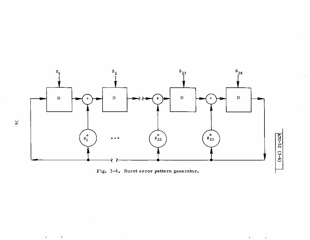
TC
-52(3-6)
76

will indicate sequentially on successive shifts the error burst patterns corxe -spending to all POEsible 24-bit burst locations within the demoddated dabblock, beginning with the burst located in the last 24 bits of the data block(the address -parity field) and endtig with the burst located in the first 24 bitsof the data block. Any of the burst error patterne cakulated by the cirtiitwodd give rise to the observed error syndrome. It thus remains to providea means for selecting which of these burst patterns is most likely to havecaused the observed nonzero error syndrome.
me demodulator produces a sequence of bit decisions from which themessage decoder calculates the error syndrome to be used for error detec -tion as well as generates candidate burst error patterns in the case of a non-sero error syndrome. me garble sensing capability of the DABS replyprocessor is intended to provide to the message decoder an indication ofwhich demodulated bits are most likely to be in error as a result of garbling.This is accomplished by the demodulator Ou@u~~g a bi~ry s equenc.e Of con-fidence indications, one for each bit decision, to indicate ‘highr or ‘low1 con-fidence in the bit decisions.
Burst error correction is then accomplished by comparing each calcu-lated 24-bit error pattern with the confidence bits corre spending to the locationof the error pattern. ~enever a burst error pattern, calcdated for a par-ticular burst location, indicates errors ody in bits that have been flagged asI1ow! confidence, then that error pattern in that location is assumed to be theone causing the nonzero syndrome. The 24-bit span of”the bit decisionsequence, corresponding to the error burst location, is then changed inaccordance with this error pattern, the burst error location search is ter-minated, and the corrected sequence is output by the decoder as the decodeddowdink message. me code properties assure that any single error burstpattern spanning a maximum of 24 bits in the bit decision sequence, in whichall bits in error are flagged as ~owi confidence bit decisions, can be correc-ted by this technique. ~ny more bits than those in error can be flagged asIlow! confidence without disrupting the decoding s theme. ~us, the garblesensing capability must flag ody actual bit errors as llow1 confidence bitdecisions with high reliability, due to the fact that tke decoder is qui$ in-sensitive to falsely flagging correct bit decision as ‘low! confidence.
h summary, since a 1- MHz dowdink data rate implies that 24 bitsspan 24 psec, the error pattern caused by a garbling ATCRBS reply of 20.75psec cannot span more than 24 bits, consequently the burst error correctioncapability of the DABS code can be used to provide immunity to garble by asingle ATCRBS reply. The error correction capability is contingent onrealizing very reliable flagging of bit decision errors as ‘low! confidence bitdecisions. E an error is utiagged or an error pattern that spans more than
* 24 bits is encountered, the decoder will attempt to correct a 24-bit burst,and this may resdt in (1 ) ~lnding no error pattern that matches the confidence
*A detailed description of the DABS downlink message decodtig system ispresented in Ref. 21.
bit sequence, and (2) finding a 24-bit error pattern that does retch the con-fidence bit sequence, resulting in a burst correction and acceptance of anincorrect message. The probability of ftiding a correctable burst error pat-tern under the preceding conditions is related to the number of bits Alselyflagged as !1owI confidence. The exact relationship between acceptingincorrect “downltik messages and the “garble sensing circuit performance inreal channel conditions is still mder investigation. Simulation resdts forthe error correction system will be presented in Section 3.5.2.
3.4 Preamble Design
DABS reply data block processing requires, at a minimum, earlyrecognition of a reply and acquisition of bit timing. ~us, the functions to berealized by a preamble waveform at the start of each DABS reply are (1 )reliable detection, and (2) reply parameter estimation in heavy ATCRBS fruitlevels. The parameter estimates of interest are TOA for target range de-termination and bit synchronization, and reply amplitude and monopuls e (off -boresight) angle estimates to be used as reference levels by the data blockprocessor. Only the TOA estimation performance will be considered here,whereas the amplitude and monopulse reference extraction from the preambleare not used by the first generation DABS reply processor. However, moreadvanced DABS reply processing techniques, which use these parameter esti-mates, have been investigated in order to better understand the fundamentallimits on DABS dowdink performance. Such advanced processing techniquescan achieve better performance in hea~ RFI than the first generation replyprocessor; they may be of real interest at some time in the future.
The preamble waveform should, of course, be constrained to usethe same basic pulse format employed in the reply data block, basically a2-MHz PAM -RNZ format. A number of pulses should be provided to allowreliable detection. Pulse edge detection should be the basic method of TOAdetermination to be compatible with ATCRBS processing techniques. De -termination of pulse TOA by the trailing edge detection in the ATCRBS re -ply processing has been determined to be much less accurate because ofmultipath, pulse stretching in the receiver, pulse width variations causedby the modulator/transmitter, etc. It was thus e stablished as a groundrule in preamble processing that only pulse leading edges would be usedto determine TOA. Thus, the preamble design problem can be stated brief-ly for the purposes of this report as the search for a 2-MHz PAM-NRZwaveforms with the number and spacings of the pulses chosen for reliabledetection (recognition) and low false abrm probability, and accurate TOAdetermination* in heavy ‘RFI environments composed of ATCRBS fruit andTACAN pulses. The preamble waveform should be kept as short as pos -sible, consistent with these requirements, and should also provide a timeinterval after the last preamble pulse for processing time to initialize thedata block processor.
‘XTO within approximately t 200 nsec for adequate bit synchronization andmonopulse sampling.
I 78

.
3. 4.1 Preamble Candidates
The simplest and shortest preamble possible would be a two-pulsepreamble that could be uniquely recognized on the basis of the leading edgespacing of the pulses. However, such a waveform is very vulnerable togarble by ATCRBS fruit since both pulse leading edges must be received inthe clear to recognize this preamble and extract TOA.
A number of four-pulse preamble designs were considered in somedetail, where the waveform structures were designed for proces sing as twopulse pairs. These preamble candidates are illustrated in Fig. 3-7. Inorder to compare performance achievable by each of these candidate pre-ambles, the following ground rules for preamble processing must be defined.
1. Detection is based on sufficient energy detected within the fourpulse intervals, the exact amount of energy required to declareindividual pulses being set by an adjustable threshold.
2. Pulses with clear leading edges are recognized, and preambledeclaration also requires at least two of the four pulses tohave clear leading edges with proper spacing.
Digital implementation of this type of preamble detection circuit forpreamble candidate 1 is presented in Fig. 3-8. The processing takes placein two stages. %lse processing determines when sufficient energy isdetected in O. 5 -~sec intervals (compared to a threshold k) to announce apulse present (output on lead P) and also simultaneously flags these detectedpulses to denote whether or not a clear leading edge was detected for each(parallel output on lead L). A stage of video processing was assumed toproduce the sampled binary) video representation that was input to this pre -amble detector. The second stage of processing consists of two shift regis -te rs (for the P and L outputs), which are tapped to check pulse locations andleading edge spacing. The circuit details the six ways in which two clearleading edges out of four pulses can occur; any of these six combinationswill be recognized by the circuit and result in the declaration of a preamble.This particular digital circuit was designed to operate at a 10 -MHz clockrate, but the same principles of operation obviously apply to any other clockrate.
3. 4.2 Preamble Performance
The basic detection/false performance for the preceding class ofpreamble detectors was investigated by digital computer simulation for allfour preamble candidates. The simulated processor includes ATCRBS(interfering) and DABS waveforms, which have been filtered by a second-order IF bandpass filter, envelope detected to produce video waveforms,
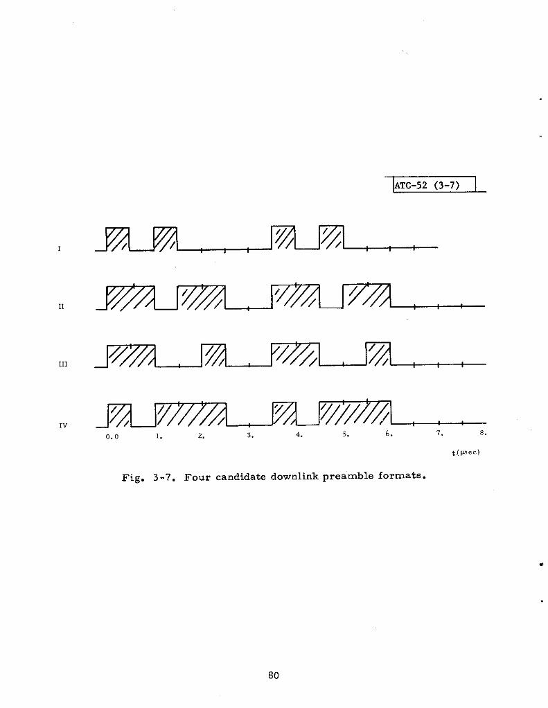
ATC-52 (3-7)
11
/ /
/~////A// / ~~///y~lIv
0.0 1. 2. 3. 4. 5. 6. 7. 8.
t(p.ec)
Fig. 3-7. Four candidate downlink preamble formats.

OUTPUT OF VIDEO I ~Pu
VP
I Y PREAMBLE DECLARED
(o) ‘U!. SE DECLARATION (b) PREAMBLE DECLARATION
Fig. 3-8. Digital preamble detector circuit for a 10-MHz clock.
*
video processed to do pulse leading and trailing edge detection (based on slopechanges of the video signal), and sampled to produce the bimry data streaminput to the preamble detector. The clock rate used in the dig~l processingwas 20 MHz.
Detection/false alarm probabilities are indicated in Fig. 3-9 for allfour candidate preambles. Detection probability (PD ) was evaluated with asingle ATCRBS reply with all (14) pulses present garbling the preamble andwith the same signal level as the preamble (SNR = 20 dB and SIR = O dB).False alarm probability (PF) was evaluated with two ATCRBS replies over-lapping and all 14 pulses present in each. The parameter Y denotes thefraction of a pulse that must be present to declare a pulse and is related tothe pulse detection threshold parameter k in the circuit of Fig. 3-8. Of thefour preamble candidates studied, preamble 1 displays significantly betterperformance than the others; cons equently only this waveform was inve sti -gated in more detail to determine if other aspects of performance wereadequate.
Both detection and TOA estimation accuracy are of interest in eval-uating the DABS preamble performance. Figure 3-10 illustrates detectionand TOA performance for situations when one and two ATCRBS replies aregarbling the preamble. k Fig. 3-10, PT(T ) denotes the probability Of de-tecting the preamble and also obtaining a TOA estimate within ~ T nsec of thetrue TOA. Curves of PD, independent of TOA accuracy, are also presentedin the plots for reference. The interference carrier frequency is assumed tobe the same as that of the preamble. Detection and TOA performance, forthe case when the A TCRBS interfering reply has a frequency that differs fromthat of the DABS preamble by 2 MHz, is illustrated in Fig. 3-11.
Preamble detection, and TOA and amplitude estimation performanceare illustrated as a function of SNR for the selected DABS preamble in Fig.3-12, where PA (a ) denotes the probability Of the cOmpound event Of (1 ) Pre -amble detection, (2) TOA estimate within * 10o nsec Of true TOA, and (3)an amplitude estimate within ~ a dB of true received amplitide.
In conclusion, it appears that preamble format 1 can provide adequatedetection and TOA performance with rather straightforward proces sing cir -cuitr y. Thus, this preamble waveform was adopted for the DABS downlinkdesign.
3.5 Downlink Performance Estimates
Tentative de sign choices for the DABS reply preamble, data modula-tion, and error correction coding were all made on the basis of providinggood immunity to ATCRBS fruit garbles. b fact, the underlying ground rulein the downlink design was to provide complete immunity to a single ATCRBSfruit reply garbling a DABS reply; the performance estimates presented thusfar have all represented specified garble conditions. It remains to provide
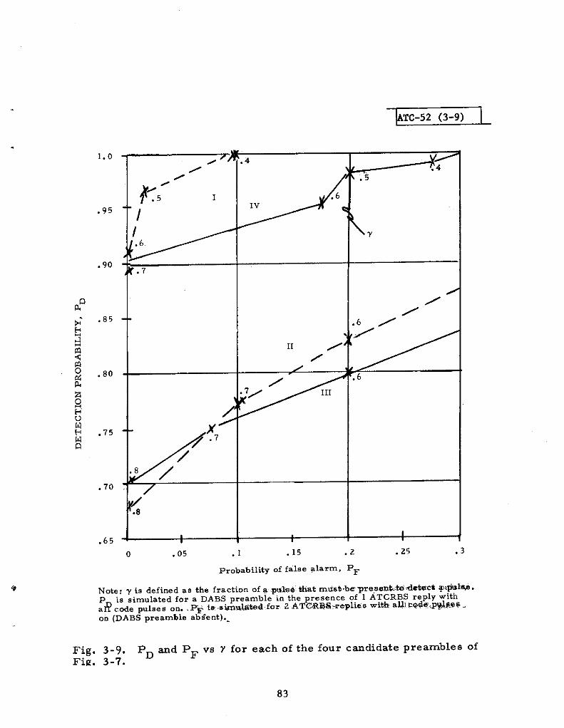
TC-52 (3-9)
11 /
/
,
i,
/“/
1
0 .05 .1 .15 .2 .25 .3
Probability of f~ls@ ?larm. P=
Note: Y is defined as the fraction of a .wkdi tit mtist -be ~~tintitu debtit q,@l~.P is simulated for a DABS preamble in the presence of 1 ATCRBS reply with.8 cod. pnlses on.. P@ ix -Stiatitif.r 2 ATCRB8weplies with a~l ?Qd@@[email protected] (DABS preamble ab *e .t).-
Fig, 3-9. PD md PF vs Y for each of the four c=didate preambles ofFig. 3-7.
83
—. ..-..-m---- . ..,,,.,,.,,,,, .,
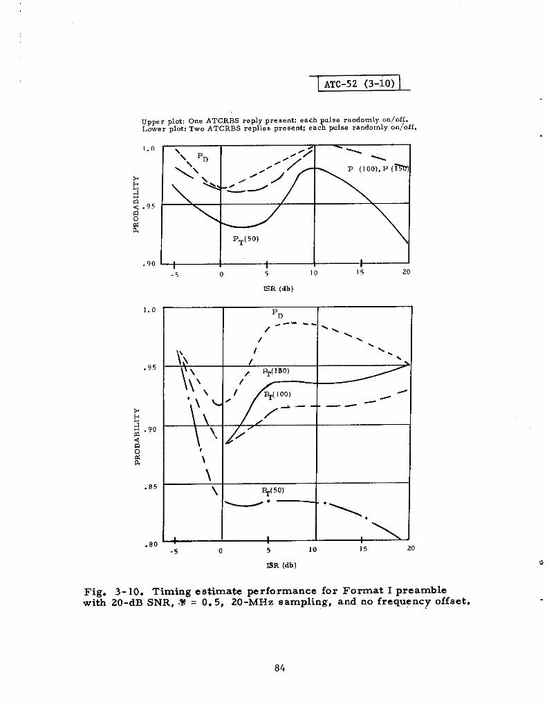
s“”““~
I
ATC-52 (3-10) I
UPP. r plot: One ATCRBS reply pres.nti each p“l,e raod.mly .ni.ff.Lower plot: TWO ATCRBS replie. pre.enti each pulee ra”d.mly .n/.ff.
\
*~~
~ .95
0ti&
PT(50)
.90 1
1.0
.95
*b35.90
<moe&
.85
.80
-5 0 ; 10 15 20
ER (db)
‘D~-..-
/ -\\
/ .
I ‘\.
/\
/ PT(1so)
// /, /
--- -— --
//
(
PT(50)
~“- ‘\,
I
-5 0 5 10 15 20
84
BR (db)
Fig. 3-10. Timing estimate ~rformance for Format I preamblewiti 20-dB SNR, Z%= O. 5, 20-MHz sampling, and no frequency offset.

ATC-52 (3-ha
(a) 1 ATCRBS reply present; each pulse randomly on/off,
---- —- —--
—b
—————— —— —-— —--
I
-5 0 5 1
BR (dB )
‘D
4
--- —-_ —-------- -.
-\-
\. ‘-
\●
I
15 20
Fig. 3-1 l(a). Timing estimate performance of Format I preamble with 20-dBSNR, Y = O. 5, 20-MHz sampling, and 2-MHz frequency offset ( 1 ATCRBSreply present).
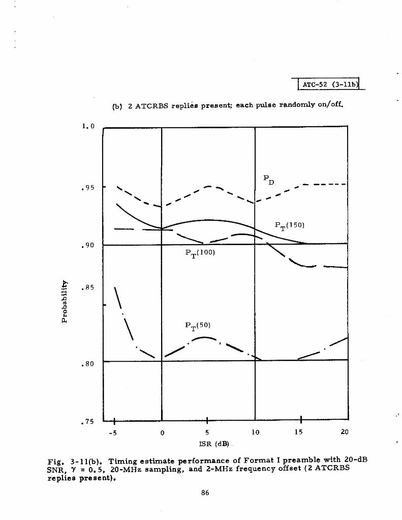
ATC-52 (3-llb
1.0
.95
.90
g .852s$~L
.80
.75
(b) 2 ATCRBS replies presenti each pdse randody on/off.
PD
,-Y----- -
‘\ \ /-\ / .
PT(l OO)
L—
\
\
PT(50)
~./
.\ /. “.. \
1 I I
-5 0 5 10 15
,,,
20
ISR (dB)
Fig. 3-l l(b). Timing estimate performance of Format I preamble with 20-dBSNR. Y = O. 5, 20-MHz sampling, and 2-MHz frequency offset (2 ATCRBSfeplies present).
86
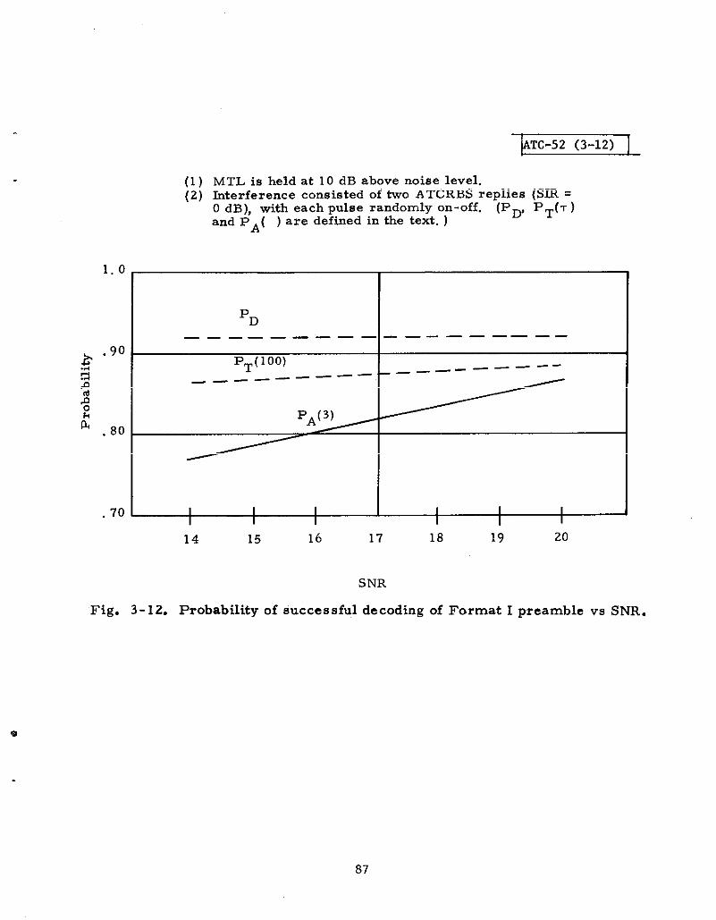
kTC-52 (3-12) I
(1)(2)
MTL is held at 10 dB above noise level.kterference consisted of two ATCRBS replies (SR =O dB), with each pulse randomly on-off. (pD, pT(T)and PA( ) are defined in the text. )
1.0
PD
——— ——— ——— ——— ———— ——
~.90
PT(l OO) _—— -—— -———- —F.
s _—— ——— —
s0
LPA(3)
.80
70~14 15 16 17 18 19 20
SNR
Fig. 3-12. Probability of successful decoding of Format I preamble vs SNR.
87

some estimate of how well each phase of DABS reply processing works inan ATCRB5 fruit environment, which will determine the rebtive frequencyof various garble conditiws.
3. 5.1 Performance Bounds
An analytical technique has been developed to calculate a lower boundon preamble performance in an ATCRBS fruit environment [Ref. 22]. Thetechnique calculates the probability of successfully detecting and declaring
a preamble (i.e. ) withfi + 100 nsec Of tie actual TOA) fOr the wOrst casefruit arrival distribution under the constraint of a given average fruit rate.The performance bound is indicated in Fig. 3-13 fOr a 20 -dB SNR, and anINR greater than 10 dB for all fruit replies. The preamble performancewill be no worse than indicated in this fi~re for any fruit arrival statisticswhatsoever (for a given average arrival rate).
The performance bounding technique has also been applied to datablOck processing. Message dec Oding performance under given garble con-ditions was first obtained by computer simulation. The probability of cor -rectly decoding the entire downlink data block was determined in thissimulation for as many as eight ATCRBS replies overlapping the data block;these data are presented in Table 3-1 for reply processing with and withouterror correction. The results were then used to determine a lower boundon correctly decoding the received data block when error correction isaccomplished and when it is not accomplished (i. e., the demodulated datais simply che eked for errors but no attempt is made to correct errorbursts). The fruit was assumed to be 90% side lobe and 10% main lobe fruit(which affects the distribution of S~). Fi~re 3-14 is an example of theprobability of correctly decoding a DABS reply with and without the bursterror correction capability as a function of “effective fruit rate, “ which isthe average arrival rate of fruit exceeding a signal level at which fruitgarbles re suit in demodulation errors.
TABLE 3-1SWULATION RESULTS FOR THE PROBABIL~Ty OF
CORRECT DATA BLOCK DECOD~G
No. of overkps: 1 23 45 678
With error correction: 1.0 0.99 0.97 0.98 0.98 0.76 0. 6Z 0..50
Without error correction: 0.91 0.74 0.62 0.29 0.22 — — —
<cFor 90 y, side lobe fruit, and 10 Y, mainbeam fruit.
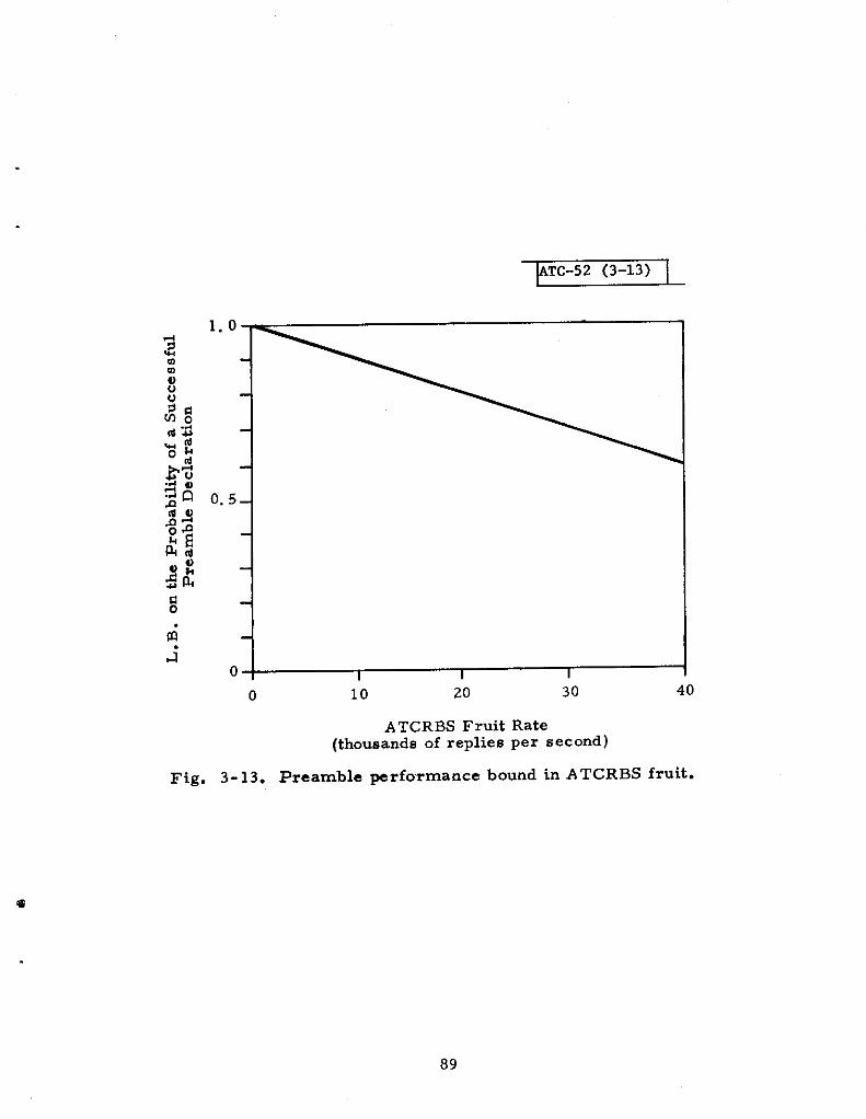
ATC-52 (3-13) I
1.0
o.5–
0 1 I I
0 10 20 30 40
A TCRBS Fruit Rate(thousands of replies per second)
Fig. 3-13. Preamble yrformance bound in ATCRBS fruit.

ATC-52 (3-14)
Lower boredwith errorcorrection
/Lower bored without
error correction
(48-bit message)
(90y. of the received fruitis sidelobe fruit)
I I I I
o 10 20 30 40
Effective’Fruit Rate
(thousands of replies per second)
Fig. 3-14. Message decoding performance in ATCRBS fruit.
’90

.
The performance bounds indicate that both the preamble detectionprobability and the correct data block decoding probability exceed 0.90 at10,000 fruit per second and exceed 0.83 at 20,000 fmit per second. Anupper bound on missed reply probability is just tie sum of the missedpreamble probability and the incorrect data block decoding probability.This results ina lower bound to the overall probability of successful re -ply processing of 0.08 in 10,000 fruit per second, and 0.66 in 20,000fruit per second.
3. 5.2 Reply Processor Simulation Studies
A general DABS reply processor simulation program has beenwritten to provide more preciqe estimates of performance in controlledATCRBS garble conditions. The sfiulatiOn prOgram includes:
. Gneration of waveforms at IF to produce true envelope varia-tions for garbling, phase incoherent pulses
. IF filtering
. Log detection to produce video waveforms
. A video pulse quantization circuit to detect leading edges andproduce binary sampled data stream
. A preamble detection circuit providing bit synchronization
. A PPM demodulator circuit that compares relative amplitide ofa s,ingle video signal sample for each PPM pulse position
. @nerationof confidence bits based on the presence of energyabove MTL in both PPM pulse positions, and also on a sidelobepulse discrimination (by comparison of signal levels receivedon the mainbeam and omni antennas)
. ATCRBS fruit model for typical traffic distribution, transpondercharacteristics, and antenna patterns
. DABS reply SNR based on uniform range distribution for DABStargets from O to 170 nmi
Some results obtained from this simulation program are presentedin Table 3-2 for three and six ATCRBS replies that overlap some part ofthe DABS preamble or data block (Or both). The last fOur rOws Of entriesin the table are for fixed DABS SNR of 15 dB and 30 dB. The results (es -pecially the last four rows) clearly indicate that a significant degree ofimmunity to ATCRBS fruit has been achieved by the downlink signal formatand reply processing.
91
The translation of fiese simdation resdts into overall dodinkperformance in a specified fruit environment is not straightforward. memethod for translation is to assume that the probability of successfully pro-cessing a DABS reply, given n garbling ATCRBS fruit replies, is a mono-tone decreasing func~lon of n. .Then the probability of “success, “ given one,two or three garbling fruit, can be lower bounded by that determined fromthe simulation for three garbling fruit. Similarly, the probability of “success: !‘given four, five or S* garbling fruit, can be Iowe r bounded by the simulationresdts for six garbling fruit. ~is type of bound has been evaluated forPoisson fruit arrival statistics, with some of “We details of the calculationsin Table 3-3. The reedts are considerably more optimistic than the mdti-plied lower bounds on calculated preamble and data block decoding successprobabilities given above.
.,
92

.w
93
..-.mr.a
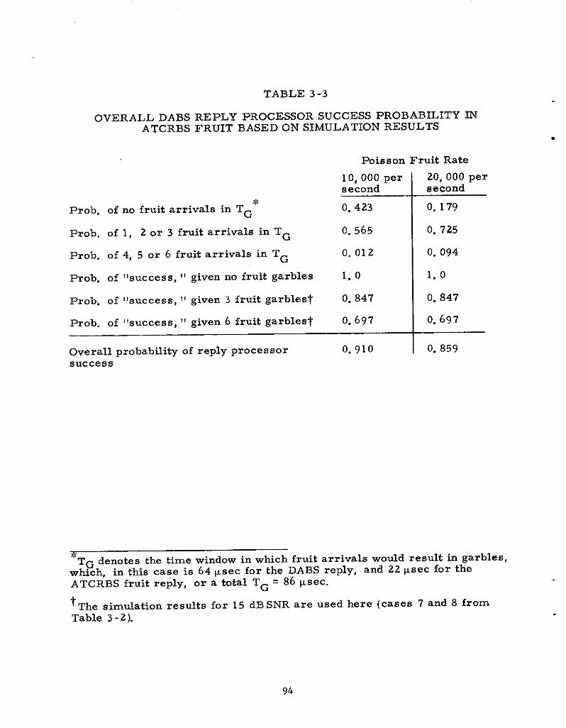
TABLE 3-3
OVERALL DABS REPLY PROCESSOR SUCCESS PROBABILITYATCRBS FRUIT BASED ON SIMULATION RESULTS
m
Poisson Fruit Rate
10, 000 per 20, 000 persecond second
P~Ob. of no fruit arrivals in TG* O. 423 0.179
Prob. Of 1, 2 or 3 fruit arrivals in ‘G O. 565 0.725
PrOb. Of 4, 5 or 6 fruit arrivals in TG 0.012 0.094
Prob. of “success, “ given no fruit garbles 1.0 1.0
Prob. of “success, “ given 3 fruit garbles~ O. 847 0.847
Prob. of “success, “ given 6 fruit garbles~ 0.697 0.697
Ove rail probability of reply processor 0.910 0.859success
“TG denotes the time window in which fruit arrivals wou3d result in garbles,which, in this case is 64 psec for the DABS reply, and 22 psec for theATCRBS fruit reply, or a total TG = 86 Msec.
‘The simdation results for 15 dB SNR are used here (cases 7 and 8 fromTable 3- 2).
.
94
.
I
4.0 SUMMARY AND CONCLUSIONS
DABS has been designed to operate on the ATCRBS frequencies of1030 and 1090 wz. The use of these frequencies demanded care~ stodyof the effects of DABS on A TGRBS functioning, and @iloring the DABS dee ignto operate satisfactorily in the RFI environment produced by ATCRBS andTACAN. The DABS link design will result in greater reliability and accuracyof surveillance than that achieved by the ATCRBS link: this will be accom-plished with significantly less effect on the A TCRBS system than an ATCRBSsensor now produces, i. e. , lower channel occupancy and lower suppressiontime for ATCRBS transponders. ti addition to the surveti~nce function,DABS will deliver critical uplink messages with very high reliability andextremely low probability of displaying messages that contain errors. Allthese features have been engineered with avionics cost cons ideration fore-most in mind, and it appears realistic to eqect a DABS transponder to costapproximately 1. 5 times the cost of an ATCRBS transponder.
The DABS uplink design was driven by the time constraint of trans -mitting uplink m es sages tiring the suppression Werval of A TCRBS tran-sponders. Although the effect of DABS sensor suppression of ATCRBStransponders is appreciable, it is predictable; the effect that DABS will haveon the ATCRBS uplink can therefore be bounded. Among simple binarymoddation s themes dictated by transponder cost constraints, there are noultra -low cost solutions. The selection of DPSK modulation is decided onthe basis of its significant performance advantages in noise and interferencewith an insignificant cost ticrement over other moddation candidates. Theconservative view of maximizing the uplink reliability in an interferenceenvironment was taken in the case of the uplink because of the difficulty ofchanging transponder Specifications to upgrade perfortince h the future.Thus, the ultimate uplink performance that one would ever expect to needmust be specified in the initial system specification. Measurements ofDABS upli~ reliability in the heaviest ATCRBS interference environmentsof the east” and west coasts of the United States verify that DABS will indeedoperate efficiently, fius minimizing channel occupancy and reinterrogation..
The DABS dotiink design was driven strongly by transponder trans -mitter cost considerations. Even in modest ATCRBS fruit environments,garbling of DABS replies by fruit will occur very frequently, dictating theneed for a high degree of immunity to such titer ference for an efficient linkdesign. Immunity has been attained by using the low-cost A TCRBS transpon-der transmitter to generate a binary PPM format, which is considerablymore immune to ATCRBS reply pulse trains than an ordinary PAM format.b addition, use of the uplink parity check code on the dowtiink providesadditional immunity to A TCRBS fruit by allowing correction of erasure burstsspanning up to 24 psec. The DABS reply charnel occupancy in time (pertarget ) is less than that of A.TCRBS,, thus mitigating DABS effects on bothATCRBS and TACAN equipment.

The DABS ltik performance is currentiy bekg verified at tie DABSExperimen~l FacUity (DABSEF), MT, Lincoln Laboratory, Lexington,mss. Nthough the environment at DABSEF is rather benign, difficdtinterference conditions are being s imdated w~e real transponders ,andhardware reply processor designs are being tested. The resdts are notcomplete, but avaflable data, ti date, indicate that the link performanceestimates presented in the earlier chapters are realistic.

I .
ACKNOWLEMMENTS
This report presents the accumulative efforts and work of many peopleat Lincoln Laboratory who contributed to the design of DABS. References tOtheir work are included in the text wherever documentation exists. Theauthor has merely attempted to summarize in a single document the mostimportant (in his mind) work supporting the selection of DABS modulationand coding designs. The author is particularly indebted to W. H. Harman forcontributions to the text of this report, and to J. T. Barrows, J. R. JO~S On,and J. D. Welch who proofread the draft of this report.
I
97

1.
2.
3.
4.
5.
6.
7.
8.
9.
10.
11.
REFERENCES
,lRePOrt of the Department Of Transportation Air Traffic COntrOl
Advisory Committee” (December 1969 ).
!! Techical Development man for a Dls crete Addres S Beacon SYstem”Department of Transportation, Report No. FAA-RD-71 -79 (oc~ber1971).
t!provisional signal FOrmats for the Discrete Address Beacon
System, ‘‘ Rev. 1, Project Report ATC-30, Rev. 1, Rewrt No.FAA-RD-74-62, Lincoln LabOratOry, M L T. (25 AprZ 1974).
P. R. Drouilhet, ,,DABS: A SYstem Description. ,, project RepOrt ‘ATC-
42, Report NO. FAA -RD-74- 189, LincOln Laboratory, M. L T.(18 November 1974).
!!U. S. National Standard for the WF Mark 8 (SW )/Air TrafficControl Radar Beacon System Characteristics, “ DOT Order10rO. 51A (8 mrch 1971).
~. ~. sam~on, et al !tDABS/ATCRBS Transponder Bench TestingprOgram-F~al Rep’Ort, ii Project Report ATC-25, RepOrt No. FAA-
RD-73 -160, Lincoln Laboratory, M I. T. (28 November 1973).
E. A. Crocker and J. R. Samson, llRepOrt on DABS/A TGRBS FieldTesting program, !! project’ Report ATC-31, Report No. FAA-RD-
74-5, Lincoln Laboratory, M. L T. (13 February 1974).
T. J. Willey and J. L. Wingard, i!potential ~terference of the Dis -
crete Address Beacon System (DABS) on the X and Y Mode TACANsystem, !I HTR1-ECAC, Report No. FAA- RD-74-14 (February 1974).
D. A. Shnidman, !!A COmWri~On Of Immuni@ to Garbling of ~ree
Candidate Modulation Schemes for DABS, “ Project Report A TC -12,Report No. FAA- RD-72-84, Lincoln Laboratory, M. I. T. (14 August1972).
D A s~idman I!The Effect of Phase Error on the DPSK Receiver
P~r~ormance, “’Project Report ATC-32, Report No. FAA-RD-74-21,Lincoln Laboratory, M L T. (4 Febr~rY 1974).
R. C. Bowes, 11. N. Criffiths, and T. B. Nichols, “ The Design andPerformance of an Experimental Selectively Addressed (A DSEL) SSRSystem, “ mE Conference Publication No. 105, “Radar Present andFuture, “ p. 32 (1973).
12.
13.
14.
15.
16.
17.
18.
19.
20.
21.
,22.
T. Kasami and S. Matoba, T,Some Efficient Shortened Cyclic Codesfor Burst-Error Correction, 1! ~EE Trans. ~ormation Theory,IT-10, p. 252 (Jdy 1964).
J. T. Barrows, !lDABS Uplink Coding, ‘t PrOjeCt Report ATC-49,Repoti No. F~-RD - 75-62, Lincok Laboratory, M. I. T. (25 JUIY1975).
T].J. Goblick and P. H. Robeck, ISAsummary of the DA.BS Transpon-der. Design/Cost Studies, !! Project Report ATC -27, Report No.FAA-RD-74- 17, Lincoln Laboratory, U I. T.’”(1 (March ~974). ~
W. H. Harman and D. A, Sbnidman, t1me Effects of A TGRBS PZ~ses on DABS Reliabili@, ” PrOject Report ATC -20, Report No.FAA- RD- 74-4, Lhcoh Laboratory, M. L T. (28 January 1’974).
llDevel~p~ent of ~ Discrete Address Beacon Systeq ‘1 QuarterlyTechnical Summary, Report No. FAA-RD-74-85, pp. 22-23, LincolnLaboratory, M I. T. (1‘ April 1974).
hid, pp. 24-25.
redevelopment of a Discrete A,ddress Beacon SyStem, ‘f QuarterlyTechnical Summary, Repoti No. FAA-RD-74- 136> pp. 18-19,Lincoln Laboratory, M I. T. (1 J~Y 1974).
R J McA,~ay t1The Effect* Of ~terferenqe on Monopulse PerfOr -~a~qd; ,, ~ec&ical No&~1,973-30, Lincoln Labotitory. ~ ~ T.
(I Au@st 1973 ),, DDC ~~69336 .
R. J. McAtiay and T. P. McGarty, 1lAn Optimum ~te rference Detec -
tor for DABS Monopylse Dab Editing, “ Tec~ical NOte 1973-48,LinCOh Laboratory, M. L T. (26 September 1973), DDC ‘An 769337’
J. T. Barrow~, !!DABS ~wnlink Coding, 11‘PrOjeCt Report A.TC-48,
Report No. FAA-RD-75 -61, Lincok Laboratory, M L T.(12 Septefibeti 1975).
J. R. Jotison,, internal Lincoln Laboratory memo. (See also “Develop-ment of a Discrete Address Beacon System, “ Qmrterly Techicalsummary, Report No. FA,A-RD-75 -114, p. 19, Lincoln Laboratory,M. L T. (1 July 1975)1
tl . . . . . . .