D633-A Series Servovalves - Moog Inc
88
DIRECT DRIVE SERVOVALVES SIZE 03 (NG6) Original User Manual (CA80942-001; Version 1.0, 12/08) USER MANUAL D633-A SERIES
Transcript of D633-A Series Servovalves - Moog Inc

DIRECT DRIVE SERVOVALVES SIZE 03 (NG6)
Original User Manual(CA80942-001; Version 1.0, 12/08)
USER MANUALD633-A SERIES

© Moog GmbH User Manual "D633-A Series" (CA80942-001; Version 1.0, 12/08) A
Copyright© 2008 Moog GmbH Hanns-Klemm-Straße 2871034 BöblingenGermany
All rights reserved. No part of this user manual may be reproduced in any form (print, photocopies, microfilm, or by any othermeans) or edited, duplicated, or distributed with electronic systems without our prior written consent. Offenders will be held liable for the payment of damages.
Subject to change without notice.
Telephone: +49 7031 622-0Fax: +49 7031 622-191E-mail: [email protected] Internet: http://www.moog.com/Industrial

Table of Contents
© Moog GmbH User Manual "D633-A Series" (CA80942-001; Version 1.0, 12/08) i
Table of ContentsCopyright ................................................................................................................................................... AList of Tables ..............................................................................................................................................vList of Figures ............................................................................................................................................vi
1 General Information ..................................................................................11.1 Notes on the user manual........................................................................................................... 1
1.1.1 Validity and subject to change without notice................................................................. 11.1.2 Completeness ................................................................................................................ 11.1.3 Storage location ............................................................................................................. 11.1.4 Typographical conventions............................................................................................. 2
1.2 Supplementing documents ........................................................................................................ 21.3 Manufacturer’s declaration......................................................................................................... 31.4 Registered trademarks................................................................................................................ 31.5 Warranty and liability .................................................................................................................. 4
2 Safety .........................................................................................................52.1 Intended operation ...................................................................................................................... 52.2 Handling in accordance with safety requirements................................................................... 62.3 Responsibilities ........................................................................................................................... 72.4 Selection and qualification of personnel .................................................................................. 82.5 Structural modifications ............................................................................................................. 82.6 Occupational safety and health ................................................................................................. 92.7 General safety instructions ........................................................................................................ 92.8 Pressure limitation .................................................................................................................... 10
3 Product Description................................................................................113.1 Function and mode of operation.............................................................................................. 11
3.1.1 Representative depiction of the valve .......................................................................... 113.1.2 Permanent magnet linear force motor.......................................................................... 123.1.3 Signal interfaces........................................................................................................... 12
3.2 Safety function/fail-safe ............................................................................................................ 133.2.1 Mechanical fail-safe functions ...................................................................................... 13
3.2.1.1 Valves with fail-safe function F, D or M ................................................... 143.2.1.2 Mechanical fail-safe state........................................................................ 143.2.1.3 Fail-safe identification.............................................................................. 143.2.1.4 Bushing-spool identification..................................................................... 15
3.2.2 Restarting the valve...................................................................................................... 153.3 Hydraulics .................................................................................................................................. 16
3.3.1 Open-loop flow control (Q-control) ............................................................................... 163.3.2 Valve configurations and hydraulic symbols ................................................................ 16
3.3.2.1 4-way and 3-way operation ..................................................................... 163.3.2.2 2-way and 2x2-way operation ................................................................. 17
3.3.3 Leakage port Y............................................................................................................. 173.3.3.1 Y-identification......................................................................................... 17
3.4 Activation ................................................................................................................................... 18

Table of Contents
© Moog GmbH User Manual "D633-A Series" (CA80942-001; Version 1.0, 12/08) ii
3.5 Nameplate .................................................................................................................................. 183.5.1 Model number .............................................................................................................. 183.5.2 Type Designation ......................................................................................................... 19
3.5.2.1 Valve version identification...................................................................... 193.5.2.2 Rated flow identification .......................................................................... 203.5.2.3 Maximum pressure identification............................................................. 203.5.2.4 Bushing-spool identification..................................................................... 213.5.2.5 Linear force motor identification .............................................................. 213.5.2.6 Fail-safe identification.............................................................................. 223.5.2.7 Y-identification......................................................................................... 223.5.2.8 Sealing material identification.................................................................. 223.5.2.9 Valve connector identification.................................................................. 23
3.5.2.10 Command signal identification ................................................................ 233.5.3 Data matrix code .......................................................................................................... 23
4 Technical Data .........................................................................................254.1 General technical data .............................................................................................................. 254.2 Hydraulic data............................................................................................................................ 264.3 Static and dynamic data ........................................................................................................... 264.4 Electrical data ............................................................................................................................ 274.5 Emissions................................................................................................................................... 27
5 Characteristic Curves .............................................................................295.1 Dependency of flow and pressure drop .................................................................................. 295.2 Flow signal characteristic curve .............................................................................................. 295.3 Spool stroke signal characteristic curve ................................................................................ 305.4 Pressure signal characteristic curve....................................................................................... 305.5 Step response and frequency response ................................................................................. 31
6 Transportation and Storage ...................................................................336.1 Unpacking/checking a delivery ................................................................................................ 346.2 Scope of delivery of the valve .................................................................................................. 346.3 Storage ....................................................................................................................................... 34
7 Mounting and Connection to the Hydraulic System............................357.1 Dimensions (installation drawings) ......................................................................................... 367.2 Mounting surface....................................................................................................................... 37
7.2.1 Surface quality.............................................................................................................. 377.2.2 Mounting pattern of mounting surface.......................................................................... 37
7.3 Mounting the valves .................................................................................................................. 387.3.1 Tools and materials required........................................................................................ 387.3.2 Specification for installation screws.............................................................................. 387.3.3 Procedure..................................................................................................................... 39
8 Electrical Connection .............................................................................418.1 Wiring ......................................................................................................................................... 42
8.1.1 Tools and materials required........................................................................................ 428.1.2 Electrical connection of the valves ............................................................................... 42
8.2 Valve connector X1 ................................................................................................................... 438.2.1 M12 valve connector X1............................................................................................... 438.2.2 MIL valve connector X1................................................................................................ 43
8.3 Grounding screw ....................................................................................................................... 44

Table of Contents
© Moog GmbH User Manual "D633-A Series" (CA80942-001; Version 1.0, 12/08) iii
9 Start-up.....................................................................................................459.1 Preparations............................................................................................................................... 479.2 Start-up of the valves ................................................................................................................ 479.3 Filling and flushing the hydraulic system............................................................................... 489.4 Start-up of the hydraulic system.............................................................................................. 49
9.4.1 Venting the hydraulic system ....................................................................................... 49
10 Operation .................................................................................................5110.1 Preparations for operation ....................................................................................................... 5210.2 Operation of the valve............................................................................................................... 5310.3 Shutting down the valve ........................................................................................................... 53
11 Service .....................................................................................................5511.1 Removing the valves................................................................................................................. 57
11.1.1 Tools and materials required........................................................................................ 5711.1.2 Procedure..................................................................................................................... 57
11.2 Maintenance............................................................................................................................... 5811.2.1 Checking and replacing the port O-rings...................................................................... 58
11.2.1.1 Tools and materials required................................................................... 5811.2.1.2 Checking and replacing the O-rings ........................................................ 58
11.3 Troubleshooting ........................................................................................................................ 5911.3.1 Leaks............................................................................................................................ 59
11.3.1.1 Leak at the valve connecting surface ...................................................... 5911.3.1.2 Leak at the linear force motor screw plug ............................................... 59
11.3.2 No hydraulic response by the valve ............................................................................. 6011.3.3 Instability of the external control loop ........................................................................... 60
11.4 Repair ......................................................................................................................................... 6111.4.1 Contact persons for repairs .......................................................................................... 61
12 Disposal ...................................................................................................63
13 Accessories and Spare Parts.................................................................6513.1 Accessories ............................................................................................................................... 6513.2 Spare parts................................................................................................................................. 66
14 Index.........................................................................................................67
15 Appendix..................................................................................................7515.1 Abbreviations, symbols and identification letters ................................................................. 7515.2 Additional literature................................................................................................................... 77
15.2.1 Moog publications ........................................................................................................ 7715.3 Quoted standards...................................................................................................................... 77
15.3.1 DIN ............................................................................................................................... 7715.3.2 DIN EN ......................................................................................................................... 7715.3.3 DIN EN ISO.................................................................................................................. 7815.3.4 EN ................................................................................................................................ 7815.3.5 IEC ............................................................................................................................... 7815.3.6 ISO ............................................................................................................................... 7815.3.7 MIL ............................................................................................................................... 78
15.4 Quoted directives ...................................................................................................................... 78

Table of Contents
© Moog GmbH User Manual "D633-A Series" (CA80942-001; Version 1.0, 12/08) iv
For your notes.

List of Tables
© Moog GmbH User Manual "D633-A Series" (CA80942-001; Version 1.0, 12/08) v
List of TablesTable 1: Position of the spool in the mechanical valve fail-safe state .......................................................... 14
Table 2: Fail-safe identification in the type designation ............................................................................... 14
Table 3: Bushing-spool identification in the type designation ...................................................................... 15
Table 4: Y-identification in the type designation........................................................................................... 17
Table 5: Valve version identification in the type designation........................................................................ 19
Table 6: Rated flow identification in the type designation ............................................................................ 20
Table 7: Maximum pressure identification in the type designation............................................................... 20
Table 8: Bushing-spool identification in the type designation ...................................................................... 21
Table 9: Linear force motor identification in the type designation ................................................................ 21
Table 10: Fail-safe identification in the type designation ............................................................................... 22
Table 11: Y-identification in the type designation........................................................................................... 22
Table 12: Sealing material identification in the type designation ................................................................... 22
Table 13: Valve version identification in the type designation........................................................................ 23
Table 14: Command signal identification in the type designation .................................................................. 23
Table 15: General technical data ................................................................................................................... 25
Table 16: Hydraulic data ................................................................................................................................ 26
Table 17: Static and dynamic data................................................................................................................. 26
Table 18: Electrical data................................................................................................................................. 27
Table 19: Specification for installation screws ............................................................................................... 38
Table 20: Accessories.................................................................................................................................... 65
Table 21: Spare parts..................................................................................................................................... 66
Table 22: Abbreviations, symbols and identification letters ........................................................................... 75

List of Figures
© Moog GmbH User Manual "D633-A Series" (CA80942-001; Version 1.0, 12/08) vi
List of FiguresFigure 1: Representative depiction of a direct drive servovalve................................................................... 11
Figure 2: Representative depiction of a permanent magnet linear force motor ........................................... 12
Figure 3: 4-way operation with mechanical fail-safe function F (hydraulic symbol) ..................................... 16
Figure 4: 3-way operation with mechanical fail-safe function F (hydraulic symbol) ..................................... 16
Figure 5: 2-way operation with mechanical fail-safe function M (hydraulic symbol)..................................... 17
Figure 6: 2x2-way operation with mechanical fail-safe function M (hydraulic symbol)................................. 17
Figure 7: Nameplate (example).................................................................................................................... 18
Figure 8: Flow signal characteristic curve .................................................................................................... 29
Figure 9: Setup for measuring the flow signal characteristic curve .............................................................. 29
Figure 10: Spool stroke signal characteristic curve........................................................................................ 30
Figure 11: Pressure signal characteristic curve of the valves with zero lap ................................................... 30
Figure 12: Setup for measuring the pressure signal characteristic curve ...................................................... 30
Figure 13: Step response of the spool stroke................................................................................................. 31
Figure 14: Frequency response of the spool stroke ....................................................................................... 31
Figure 15: Installation drawings for valves with M12 or MIL valve connector, dimensions in mm (inches).... 36
Figure 16: Mounting pattern of mounting surface as per ISO 4401-03-03-0-05, dimensions in mm (inches) 37
Figure 17: M12 valve connector X1 (circuit and pin assignment)................................................................... 43
Figure 18: MIL valve connector X1 (circuit and pin assignment).................................................................... 43
Figure 19: Grounding screw ........................................................................................................................... 44
Figure 20: Repair quality seal......................................................................................................................... 61

1 General Information Notes on the user manual
© Moog GmbH User Manual "D633-A Series" (CA80942-001; Version 1.0, 12/08) 1
1 General Information
1.1 Notes on the user manualNotes on the user manualThis user manual applies only to the standard models of D633-A series valves.
It contains the most important information for ensuring proper and correct oper-ation of the valves.
Chapter "2.1 Intended operation", page 5Chapter "2.2 Handling in accordance with safety requirements", page 6
The contents of this user manual and the product-related hardware and soft-ware documentation relevant to the particular application must be read, under-stood and followed in all points by each person responsible for machine plan-ning, assembly and operation before work with and on the valves is started.This requirement applies in particular to the safety instructions.
Chapter "1.1.2 Completeness", page 1Chapter "2.3 Responsibilities", page 7Chapter "2.4 Selection and qualification of personnel", page 8Chapter "2.2 Handling in accordance with safety requirements", page 6
This user manual has been prepared with great care in compliance with the rel-evant regulations, state-of-the-art technology and our many years of knowl-edge and experience. The full contents have been generated to the best of theauthors’ knowledge. However, the possibility of error remains and improvements are possible.Please feel free to submit any comments about possible errors and incompleteinformation to us.
1.1.1 Validity and subject to change without noticeValidity of the user manual and subject to change without notice
The information contained in this user manual is valid and correct at the mo-ment of release of this version of the user manual. The version number and re-lease date of this user manual are indicated in the footer.
Changes may be made to this user manual at any time and without reasonsbeing given.
1.1.2 CompletenessCompleteness of the user manual
This user manual is only complete in conjunction with the product-related hard-ware and software documentation required for the relevant application.Available documents:
Chapter "1.2 Supplementing documents", page 2
1.1.3 Storage locationStorage location for the user manual
This user manual together with all of the product-related hardware and soft-ware documentation relevant to the particular application must be kept ready tohand and accessible close to the valve or the higher-level machine at all times.
Special models of the valves custom-made for specific customers are notexplained in this user manual.Please contact us or one of our authorized service centers for informationon these special models.

1 General Information Supplementing documents
© Moog GmbH User Manual "D633-A Series" (CA80942-001; Version 1.0, 12/08) 2
1.1.4 Typographical conventions
Typographical conventions
1.2 Supplementing documents
Supplementing documents
The following supplementing documents are available:• Application notes "Technical Note TN 353"
Protective grounding and electrical shielding of hydraulic valves with integrated electronics
• Application notes "Technical Note TN 494"Maximum permissible lengths of electric cables for the connection of hydraulic valves with integrated electronics
DANGER Identifies safety instructions which are intended to warnof immediately imminent danger to life and limb or seriousdamage to property.Failure to comply with these safety instructions will inevi-tably result in fatalities, serious personal injuries (disable-ment) or serious damage to property!
WARNING Identifies safety instructions which are intended to warnof possible danger to life and limb or possible seriousdamage to property.Failure to comply with these safety instructions may result infatalities, serious personal injuries (disablement) or seriousdamage to property!
CAUTION Identifies safety instructions which are intended to warn of mi-nor personal injuries or minor damage to property.Failure to comply with these safety instructions may result inminor personal injuries or minor damage to property.
Identifies important notes/information
• or – Identifies listings
Identifies references to another chapter, another page, table orillustration in the user manual
"…" Identifies headings of chapters or titles of documents, whichare referenced
Blue text Identifies hyperlinks in the PDF file
1., 2., … Identifies steps in a procedure which must be performed inconsecutive order
Identifies the direction of the valve opening (e.g., P T)
The supplementing documents mentioned here are not included in thevalves’ scope of delivery. They are available as accessories.
Chapter "13.1 Accessories", page 65The PDF files of the supplementing documents can be downloaded fromthe following link:http://www.moog.com/Industrial/Literature

1 General Information Manufacturer’s declaration
© Moog GmbH User Manual "D633-A Series" (CA80942-001; Version 1.0, 12/08) 3
1.3 Manufacturer’s declarationManufacturer’s declaration
The valves comply with the standards specified in the associated manufac-turer’s declaration.The valves comply with the requirements of the Machine Directive 98/37/EC.Refer to the associated manufacturer’s declaration for the applied standards.
1.4 Registered trademarksRegistered trademarks Moog and Moog Authentic Repair® are registered trademarks of Moog Inc. and
its subsidiaries.
Microsoft® and Windows® are either registered trademarks or trademarks ofthe Microsoft® Corporation in the USA and/or other countries.
Please contact us or one of our authorized service centers for the manu-facturer’s declaration.
All of the product and company names mentioned in this user manual arepossibly registered names or trademarks of the respective manufacturers.The use of these names by third parties for their own purposes may in-fringe the rights of the manufacturers.The absence of the symbols ® or ™ does not indicate that the name isfree from trademark protection.
1 General Information Warranty and liability
© Moog GmbH User Manual "D633-A Series" (CA80942-001; Version 1.0, 12/08) 4
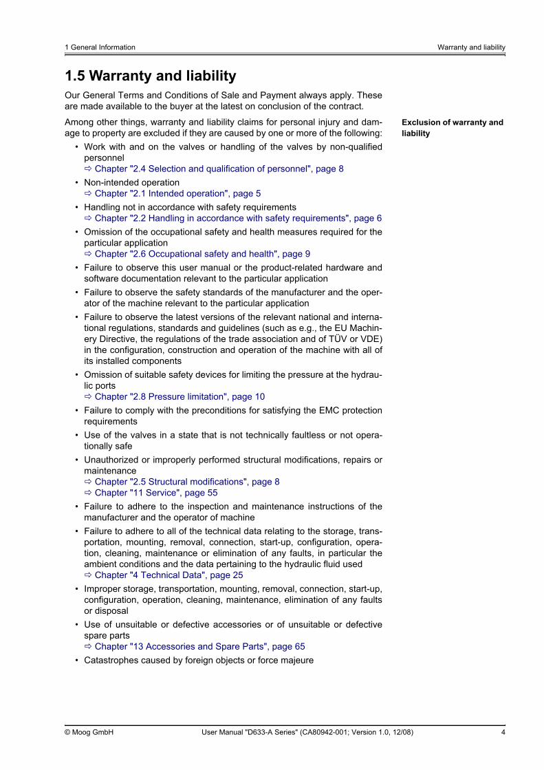
1.5 Warranty and liabilityOur General Terms and Conditions of Sale and Payment always apply. Theseare made available to the buyer at the latest on conclusion of the contract.
Exclusion of warranty and liability
Among other things, warranty and liability claims for personal injury and dam-age to property are excluded if they are caused by one or more of the following:
• Work with and on the valves or handling of the valves by non-qualifiedpersonnel
Chapter "2.4 Selection and qualification of personnel", page 8• Non-intended operation
Chapter "2.1 Intended operation", page 5• Handling not in accordance with safety requirements
Chapter "2.2 Handling in accordance with safety requirements", page 6• Omission of the occupational safety and health measures required for the
particular applicationChapter "2.6 Occupational safety and health", page 9
• Failure to observe this user manual or the product-related hardware andsoftware documentation relevant to the particular application
• Failure to observe the safety standards of the manufacturer and the oper-ator of the machine relevant to the particular application
• Failure to observe the latest versions of the relevant national and interna-tional regulations, standards and guidelines (such as e.g., the EU Machin-ery Directive, the regulations of the trade association and of TÜV or VDE)in the configuration, construction and operation of the machine with all ofits installed components
• Omission of suitable safety devices for limiting the pressure at the hydrau-lic ports
Chapter "2.8 Pressure limitation", page 10• Failure to comply with the preconditions for satisfying the EMC protection
requirements• Use of the valves in a state that is not technically faultless or not opera-
tionally safe• Unauthorized or improperly performed structural modifications, repairs or
maintenanceChapter "2.5 Structural modifications", page 8Chapter "11 Service", page 55
• Failure to adhere to the inspection and maintenance instructions of themanufacturer and the operator of machine
• Failure to adhere to all of the technical data relating to the storage, trans-portation, mounting, removal, connection, start-up, configuration, opera-tion, cleaning, maintenance or elimination of any faults, in particular theambient conditions and the data pertaining to the hydraulic fluid used
Chapter "4 Technical Data", page 25• Improper storage, transportation, mounting, removal, connection, start-up,
configuration, operation, cleaning, maintenance, elimination of any faultsor disposal
• Use of unsuitable or defective accessories or of unsuitable or defectivespare parts
Chapter "13 Accessories and Spare Parts", page 65• Catastrophes caused by foreign objects or force majeure

2 Safety Intended operation
© Moog GmbH User Manual "D633-A Series" (CA80942-001; Version 1.0, 12/08) 5
2 Safety
2.1 Intended operationIntended operation
The valves may only be operated as a component part of a higher-level overallsystem, for example in a machine.They may be used only as control elements to control flow and/or pressure inhydraulic circuits that regulate position, speed, pressure and power. The valves are intended for use with mineral-oil-based hydraulic oils. Use withother media requires our prior approval.Correct, reliable and safe operation of the valves requires qualified projectplanning as well as proper utilization, transportation, storage, mounting, re-moval, electrical and hydraulic connection, start-up, configuration, operation,cleaning and maintenance.
The valves may only be started up when the following is ensured:• The higher-level machine with all of its installed components complies
with the latest versions of the relevant national and international regula-tions, standards and guidelines (such as e.g., the EU Machinery Directive,the regulations of the trade association and of TÜV or VDE).
• The valves and all of the other installed components are in a technicallyfault-free and operationally reliable state.
• No signals which can lead to uncontrolled movements in the machine aretransmitted to the valves.
Intended operation also includes the following:• Observation of this user manual• Handling of the valves in accordance with safety requirements
Chapter "2.2 Handling in accordance with safety requirements", page 6• Adherence to all of the inspection and maintenance instructions of the
manufacturer and the operator of the machine• Observation of all product-related hardware and software documentation
relevant to the particular application• Observation of all safety standards of the manufacturer and the operator
of the machine relevant to the particular application• Observation of all the latest versions of the national and international reg-
ulations, standards and guidelines relevant to the particular application(such as e.g., the EU Machinery Directive, the regulations of the trade as-sociation and of TÜV or VDE)
WARNING The valves may be operated exclusively within the frame-work of the data and applications specified in the usermanual.Any other or more extensive use is not permitted.
WARNING Use of the valves in potentially explosive environments isnot permitted.

2 Safety Handling in accordance with safety requirements
© Moog GmbH User Manual "D633-A Series" (CA80942-001; Version 1.0, 12/08) 6
Handling in accordance with safety requirements
In order to ensure that the valves are handled in accordance with safety re-quirements and operated without faults, it is essential to observe the following:
• All of the safety instructions in the user manual• All of the safety instructions in the product-related hardware and software
documentation relevant to the particular application• All of the safety instructions in the safety standards of the manufacturer
and the operator of the machine relevant to the particular application• All of the relevant national and international safety and accident preven-
tion regulations, standards and guidelines, such as e.g., the safety regula-tions of the trade association, of TÜV or VDE, in particular the followingstandards pertaining to the safety of machinery:
– DIN EN ISO 12100– DIN EN 982– DIN EN 563– EN 60204
Observing the safety instructions and the safety and accident prevention regu-lations, standards and guidelines will help to prevent accidents, malfunctionsand damage to property!
2.2 Handling in accordance with safety requirements
WARNING It is the responsibility of the manufacturer and the opera-tor of the machine to ensure that the valves are handled inaccordance with safety requirements.
WARNING As in any electronic control system, the failure of certaincomponents in valves as well might lead to an uncon-trolled and/or unpredictable operational sequence. Alltypes of failure on a system level must be taken into con-sideration and appropriate protective measures must betaken.The use of automatic control technology in a machine calls forspecial measures.If automatic control technology is to be used, the user should,in addition to all of the potentially available standards or guide-lines on safety-engineering installations, consult the manufac-turers of the components used in great depth.

2 Safety Responsibilities
© Moog GmbH User Manual "D633-A Series" (CA80942-001; Version 1.0, 12/08) 7
2.3 ResponsibilitiesResponsibility of the manufacturer and the operator of the machine
The manufacturer and the operator of the machine are responsible for ensuringthat work with and on the valves and handling of the valves is planned and per-formed in accordance with the directions given in this user manual and in theproduct-related hardware and software documentation relevant to the particu-lar application. The manufacturer and the operator of the machine are in particular responsiblefor ensuring the following:
• Selection and training of personnelChapter "2.4 Selection and qualification of personnel", page 8
• Intended operationChapter "2.1 Intended operation", page 5
• Handling in accordance with safety requirementsChapter "2.2 Handling in accordance with safety requirements", page 6
• Taking and monitoring of the occupational safety and health measures re-quired for the particular application
Chapter "2.6 Occupational safety and health", page 9• Observation of all of the safety standards of the manufacturer and the op-
erator of the machine relevant to the particular application• Observation of the latest versions of the relevant national and interna-
tional regulations, standards and guidelines (such as e.g., the EU Machin-ery Directive, the regulations of the trade association and of TÜV or VDE)in the configuration, construction and operation of the machine with all ofits installed components
• Installation of suitable safety devices for limiting the pressure at the hy-draulic ports
Chapter "2.8 Pressure limitation", page 10• Compliance with the preconditions for satisfying the EMC protection re-
quirements• Use of the valves in a technically faultless and operationally safe state• Prevention of unauthorized or improperly performed structural modifica-
tions, repairs or maintenanceChapter "2.5 Structural modifications", page 8Chapter "11 Service", page 55
• Definition and observation of the application-specific inspection and main-tenance instructions
• Adherence to all of the technical data relating to the storage, transporta-tion, mounting, removal, connection, start-up, configuration, operation,cleaning, maintenance or elimination of any faults, in particular the ambi-ent conditions and the data pertaining to the hydraulic fluid used
Chapter "4 Technical Data", page 25• Proper storage, transportation, mounting, removal, connection, start-up,
configuration, operation, cleaning, maintenance, elimination of any faultsor disposal
• Use of suitable and faultless accessories and of suitable and faultlessspare parts
Chapter "13 Accessories and Spare Parts", page 65• Handy and accessible storage of this user manual and of the product-re-
lated hardware and software documentation relevant to the particular ap-plication
Chapter "1.1.3 Storage location", page 1

2 Safety Selection and qualification of personnel
© Moog GmbH User Manual "D633-A Series" (CA80942-001; Version 1.0, 12/08) 8
2.4 Selection and qualification of personnelSelection and qualification of personnel
Qualified users Qualified users are specialized personnel with the required knowledge and ex-perience who have been trained to carry out such work. The specialized per-sonnel must be able to recognize and avert the dangers which they are ex-posed to when working with and on the valves.In particular, these specialized personnel must be authorized to operate,earth/ground and mark hydraulic and electrical devices, systems and powercircuits in accordance with the standards of safety engineering. Project plan-ners must be fully conversant with automation safety concepts.
Warranty and liability claims for personal injury or damage to property areamong others excluded if such injury or damage is caused when the valves areworked on or handled by non-qualified personnel.
Chapter "1.5 Warranty and liability", page 4
2.5 Structural modificationsStructural modifications
Warranty and liability claims for personal injury and damage to property areamong others excluded if they are caused by unauthorized or improperly per-formed structural modifications or other interventions.
Chapter "1.5 Warranty and liability", page 4
WARNING Only properly qualified and authorized users may workwith and on the valves.
WARNING In the interests of avoiding damage to the valves or acces-sories, structural modifications, on account of the com-plexity of the internal components of the valves or acces-sories, may only be carried out by us or one of our autho-rized service centers.

2 Safety Occupational safety and health
© Moog GmbH User Manual "D633-A Series" (CA80942-001; Version 1.0, 12/08) 9
2.6 Occupational safety and healthOccupational safety and health measures and equipment
2.7 General safety instructionsGeneral safety instructions
WARNING The magnets in the permanent magnet linear force motorcreate strong magnetic fields, which can have a disruptiveeffect on sensitive devices, such as e.g., cardiac pace-makers. The relevant safe distances appropriate for thedevice must be observed.
CAUTION Depending on the application, significant levels of noise maybe generated when the valves are operated. If necessary, the manufacturer and operator of the machinemust take appropriate sound insulation measures or stipulatethat suitable safety equipment, such as e.g., ear protection, beworn.
CAUTION Falling objects, such as e.g., valve, tool or accessory, cancause injury.Suitable safety equipment, such as e.g., safety shoes, must beworn to provide protection against injury.
CAUTION Valves and hydraulic port lines can become very hot during op-eration.Suitable safety equipment, such as e.g., work gloves, must beworn to provide protection against injury before touching thevalve or the connection cables during such operations asmounting, removal, electrical and hydraulic connection, trou-bleshooting or servicing.
CAUTION When handling hydraulic fluids, observe the safety provisionsapplicable to the hydraulic fluid used.If necessary, suitable safety equipment, such as e.g., workgloves, must be worn.
WARNING Only properly qualified and authorized users may workwith and on the valves.
Chapter "2.4 Selection and qualification of personnel", page 8
WARNING Observe and adhere to the technical data and in particularthe information given on the valve nameplate.
Chapter "4 Technical Data", page 25
CAUTION This user manual and the product-related hardware and soft-ware documentation relevant to the particular application mustbe inserted in the machine’s operating instructions.

2 Safety Pressure limitation
© Moog GmbH User Manual "D633-A Series" (CA80942-001; Version 1.0, 12/08) 10
2.8 Pressure limitationSafety devices for pressure limitation
WARNING Excessive pressure at the hydraulic ports damages thevalve and can cause unsafe states in the machine and per-sonal injury.Pressure-limiting valves, for example, or other comparablesafety devices must be installed to limit the pressure at all ofthe hydraulic ports to the specified maximum operating pres-sure.Maximum operating pressure:
Chapter "4 Technical Data", page 25

3 Product Description Function and mode of operation
© Moog GmbH User Manual "D633-A Series" (CA80942-001; Version 1.0, 12/08) 11
3 Product Description
3.1 Function and mode of operationFunction of the valves: throttle valves
The valves of the D633-A series are direct drive servovalves (DDV: DirectDrive Valve). The valves are throttle valves for 2-, 3-, 4- or even 2x2-way appli-cations. They are suitable for electrohydraulic position, speed, pressure and force con-trol even for high dynamic requirements. They control flow.
3.1.1 Representative depiction of the valve
Representative depiction of the valve
Figure 1: Representative depiction of a direct drive servovalve
Item Designation Further information
1 Grounding screw Chapter "8.3 Grounding screw", page 44
2 Valve connector X1 Chapter "8.2 Valve connector X1", page 43
3 Spool
4 Bushing
5 Permanent magnet linear force motor
Chapter "3.1.2 Permanent magnet linear force motor", page 12
T…Y Ports Chapter "7.2.2 Mounting pattern of mounting surface", page 37

3 Product Description Function and mode of operation
© Moog GmbH User Manual "D633-A Series" (CA80942-001; Version 1.0, 12/08) 12
3.1.2 Permanent magnet linear force motor
Representative depiction of a permanent magnet linear force motor
Figure 2: Representative depiction of a permanent magnet linear force motor
Permanent magnet linear force motor
A permanent magnet linear force motor (figure 2 or item 10 in figure 1) is usedto drive the valve spool (item 8 in figure 1). In contrast to proportional-solenoid drives, the permanent magnet linear forcemotor can move the spool from the spring-centered center position in bothworking directions. This results in high actuating power for the spool simulta-neously with very good static and dynamic properties.The permanent magnet linear force motor is a differential motor excited by per-manent magnets. Some of the magnetic force is already provided by the per-manent magnets. The linear force motor’s power demand is thus significantlylower than is the case with comparable proportional solenoids.The linear force motor (figure 2 or item 10 in figure 1) drives the valve spool(item 8 in figure 1). The spool starting position is determined in the de-ener-gized state by the centering springs (item 5 in figure 2). The linear force motorenables the spool to be displaced from the starting position in both directions.Here, the actuating power of the linear force motor is proportional to the coilcurrent. The high forces of the linear force motor and centering springs effect precisespool movement even against flow and frictional forces.
3.1.3 Signal interfacesThe valves are provided with a valve connector X1 for the command signal.Pin assignment of valve connector X1:
Chapter "8.2 Valve connector X1", page 43
Item Designation
1 Coil
2 Bearing
3 Armature
4 Permanent magnets
5 Centering springs
6 Screw plug

3 Product Description Safety function/fail-safe
© Moog GmbH User Manual "D633-A Series" (CA80942-001; Version 1.0, 12/08) 13
3.2 Safety function/fail-safe
Mechanical fail-safe functions
The mechanical valve fail-safe functions increase the safety of the user if thecommand signal fails.
Chapter "3.2.1 Mechanical fail-safe functions", page 13
Mechanical fail-safe state The valve is rendered in the mechanical fail-safe state if the command signalfails. The mechanical valve fail-safe state is denoted by the fact that the spoolis in a defined spring-determined position.
Chapter "3.2.1.2 Mechanical fail-safe state", page 14
It is essential to ensure at the machine end that the fail-safe state results in asafe state in the machine.
The valve must be restarted after its transition into the fail-safe state.Chapter "3.2.2 Restarting the valve", page 15
3.2.1 Mechanical fail-safe functionsMechanical fail-safe functions
The following mechanical fail-safe functions are available:• Fail-safe function F• Fail-safe function D• Fail-safe function M
WARNING It is essential to observe the notes/information on han-dling in accordance with safety requirements particularlyin the case of safety-critical applications.
Chapter "2.2 Handling in accordance with safety require-ments", page 6
WARNING The manufacturer and the operator of the machine are re-sponsible for ensuring that, when the machine is config-ured, designed and operated with all of the installed com-ponents, the latest version of the safety standards rele-vant to safety-critical applications applicable to avertingdamage are observed.It is vital among other things to ensure that both the individualcomponents and the complete machine can be rendered in asafe state.
It is necessary when ordering the valve to establish which mechanical fail-safe function is to be integrated in the valve.Which mechanical fail-safe function is integrated in the valve can be as-certained from the fail-safe identification, i.e., the 6th position in the valvetype designation.
Chapter "3.2.1.3 Fail-safe identification", page 14
3 Product Description Safety function/fail-safe
© Moog GmbH User Manual "D633-A Series" (CA80942-001; Version 1.0, 12/08) 14
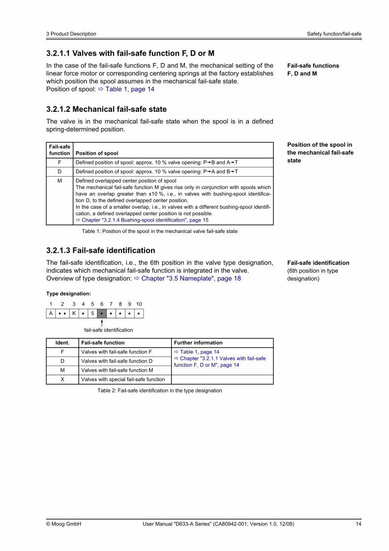
3.2.1.1 Valves with fail-safe function F, D or MFail-safe functions F, D and M
In the case of the fail-safe functions F, D and M, the mechanical setting of thelinear force motor or corresponding centering springs at the factory establisheswhich position the spool assumes in the mechanical fail-safe state.Position of spool: Table 1, page 14
3.2.1.2 Mechanical fail-safe stateThe valve is in the mechanical fail-safe state when the spool is in a definedspring-determined position.
Position of the spool in the mechanical fail-safe state
3.2.1.3 Fail-safe identificationFail-safe identification (6th position in type designation)
The fail-safe identification, i.e., the 6th position in the valve type designation,indicates which mechanical fail-safe function is integrated in the valve.Overview of type designation: Chapter "3.5 Nameplate", page 18
Fail-safe function Position of spool
F Defined position of spool: approx. 10 % valve opening: P B and A T
D Defined position of spool: approx. 10 % valve opening: P A and B T
M Defined overlapped center position of spoolThe mechanical fail-safe function M gives rise only in conjunction with spools whichhave an overlap greater than ±10 %, i.e., in valves with bushing-spool identifica-tion D, to the defined overlapped center position.In the case of a smaller overlap, i.e., in valves with a different bushing-spool identifi-cation, a defined overlapped center position is not possible.
Chapter "3.2.1.4 Bushing-spool identification", page 15
Table 1: Position of the spool in the mechanical valve fail-safe state
Type designation:
1 2 3 4 5 6 7 8 9 10
A • • K • 5 • • • • •
Ident. Fail-safe function Further information
F Valves with fail-safe function F Table 1, page 14Chapter "3.2.1.1 Valves with fail-safe
function F, D or M", page 14D Valves with fail-safe function D
M Valves with fail-safe function M
X Valves with special fail-safe function
Table 2: Fail-safe identification in the type designation
fail-safe identification

3 Product Description Safety function/fail-safe
© Moog GmbH User Manual "D633-A Series" (CA80942-001; Version 1.0, 12/08) 15
3.2.1.4 Bushing-spool identificationBushing-spool identification (4th position in type designation)
The bushing-spool identification, i.e., the 4th position in the valve type designa-tion, indicates which bushing-spool version is integrated in the valve.Overview of type designation: Chapter "3.5 Nameplate", page 18
3.2.2 Restarting the valve
Restarting the valve
After shutdown/failure of the command signal:After the transition of the valve into the fail-safe state on account of a shut-down/failure of the command signal to the valve, it will be necessary to restartthe valve by applying the command signal in accordance with the technicaldata.
Type designation:
1 2 3 4 5 6 7 8 9 10
A • • K • 5 • • • • •
Ident. Valve configuration Bushing-spool version
O 4-way Linear characteristic curve, zero lap
A 4-way Linear characteristic curve, ±1.5 % to ±3 % positive overlap
D 4-way Linear characteristic curve, ±10 % positive overlap
B 3-way Valve opening: P A and A T
Z 2x2-way Valve opening: P A and B T (externally connect P with B and A with T), with port Y only
X Special spool, on request
Table 3: Bushing-spool identification in the type designation
bushing-spool identification
WARNING Before restarting the valve after the transition of the valveinto the fail-safe state, it is necessary to identify and ifnecessary rectify the cause of the fault at the machineend.It is also necessary to ensure that restarting the valvedoes not give rise to unintentional or dangerous states inthe machine.
3 Product Description Hydraulics
© Moog GmbH User Manual "D633-A Series" (CA80942-001; Version 1.0, 12/08) 16
3.3 Hydraulics3.3.1 Open-loop flow control (Q-control)
Operational mode: Open-loop flow control (Q-control)
The valves are operated as open-loop flow control valves. In open-loop flow control an open-loop control of the spool position is carriedout. The predefined command signal corresponds to a particular spool position.The flow that is set depends not only on the spool position but also on the pres-sure difference ∆p at the individual control lands.
Chapter "5.1 Dependency of Flow and Pressure Drop", page 29Chapter "5.2 Flow signal characteristic curve", page 29
3.3.2 Valve configurations and hydraulic symbolsValve configurations Depending on the model, the following valve configurations are possible:
• 2-way operationChapter "3.3.2.2 2-way and 2x2-way operation", page 17
• 3-way operationChapter "3.3.2.1 4-way and 3-way operation", page 16
• 4-way operationChapter "3.3.2.1 4-way and 3-way operation", page 16
• 2x2-way operationChapter "3.3.2.2 2-way and 2x2-way operation", page 17
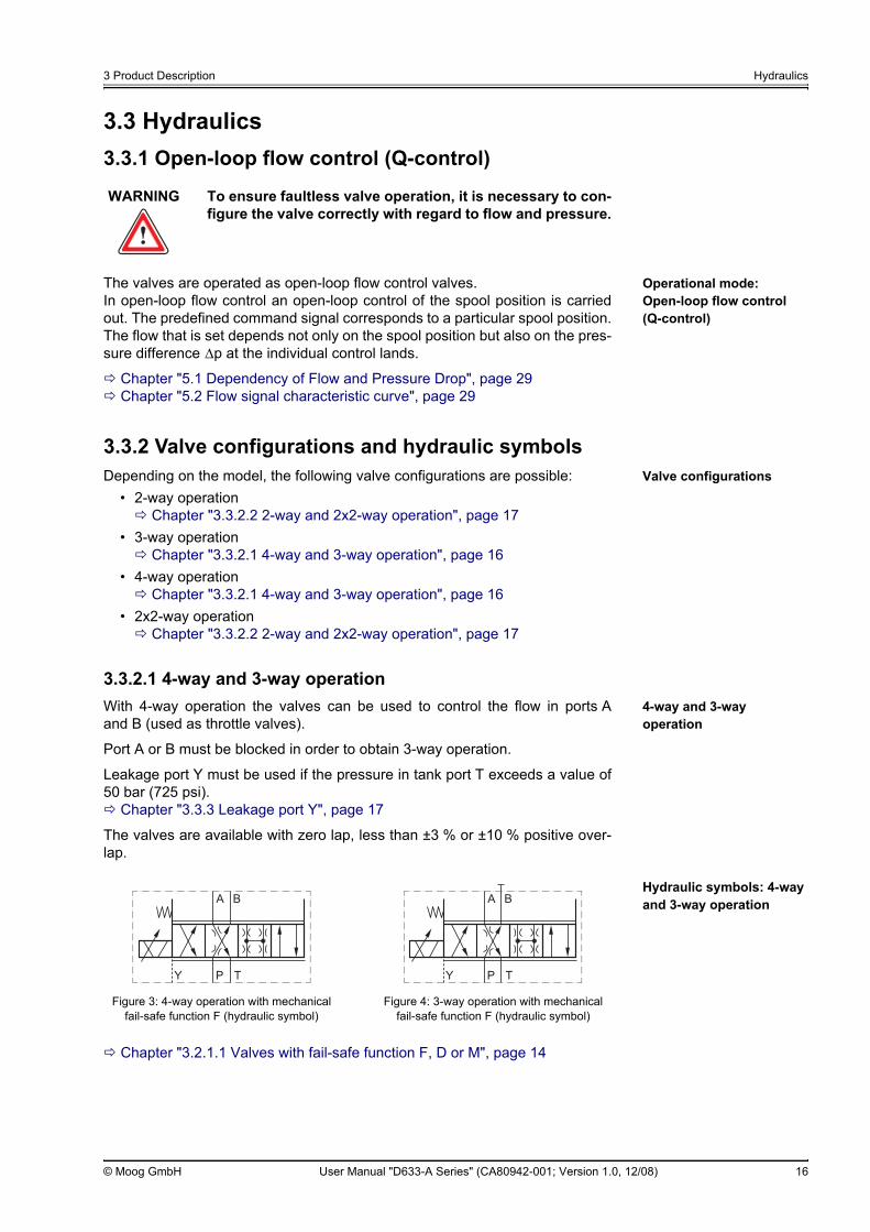
3.3.2.1 4-way and 3-way operation4-way and 3-way operation
With 4-way operation the valves can be used to control the flow in ports Aand B (used as throttle valves).
Port A or B must be blocked in order to obtain 3-way operation.
Leakage port Y must be used if the pressure in tank port T exceeds a value of50 bar (725 psi).
Chapter "3.3.3 Leakage port Y", page 17
The valves are available with zero lap, less than ±3 % or ±10 % positive over-lap.
Hydraulic symbols: 4-way and 3-way operation
Chapter "3.2.1.1 Valves with fail-safe function F, D or M", page 14
WARNING To ensure faultless valve operation, it is necessary to con-figure the valve correctly with regard to flow and pressure.
Figure 3: 4-way operation with mechanical fail-safe function F (hydraulic symbol)
Figure 4: 3-way operation with mechanical fail-safe function F (hydraulic symbol)

3 Product Description Hydraulics
© Moog GmbH User Manual "D633-A Series" (CA80942-001; Version 1.0, 12/08) 17
3.3.2.2 2-way and 2x2-way operation2-way and 2x2-way operation
With 2-way and 2x2-way operation the valves can be used to control the flow inone direction (used as throttle valves).
With 2x2-way operation the valve can be used in 2-way applications for greaterflows. Ports P with B and A with T must be externally connected for this purpose.The direction of flow must be observed as per figure 6.
Chapter "3.2.1.1 Valves with fail-safe function F, D or M", page 14
3.3.3 Leakage port YLeakage port Y Leakage port Y must be used in the following cases:
• when the pressure pT in tank port T is greater than 50 bar (725 psi)• with 2x2-way operation
3.3.3.1 Y-identificationY-identification (7th position in type designation)
The Y-identification, i.e., the 7th position in the valve type designation, indi-cates how leakage port Y is configured in the valve.Overview of type designation: Chapter "3.5 Nameplate", page 18
Leakage port Y must always be connected with 2x2-way operation.Chapter "3.3.3 Leakage port Y", page 17
Figure 5: 2-way operation with mechanical fail-safe function M (hydraulic symbol)
Figure 6: 2x2-way operation with mechanical fail-safe function M (hydraulic symbol)
The valve can be supplied either with or without leakage port Y. It is necessary when ordering the valve to establish whether leakageport Y is to be used.Whether leakage port Y is used can be ascertained from the Y-identifica-tion, i.e., the 7th position in the type designation.
Chapter "3.3.3.1 Y-identification", page 17
Type designation:
1 2 3 4 5 6 7 8 9 10
A • • K • 5 • • • • •
Ident. Leakage port Y Can be used at
0 Closed, with screw plug Pressure in tank port pT ≤ 50 bar (725 psi)
3 Open, with filter element Pressure in tank port pT > 50 bar (725 psi)
Table 4: Y-identification in the type designation
Y-identification

3 Product Description Activation
© Moog GmbH User Manual "D633-A Series" (CA80942-001; Version 1.0, 12/08) 18
3.4 ActivationActivation of the valves The valves are controlled with a command signal via the valve connector X1.
Chapter "3.1.3 Signal interfaces", page 12Chapter "3.5.2.10 Command signal identification", page 23
3.5 NameplateNameplate
Figure 7: Nameplate (example)
3.5.1 Model numberModel number The model number is set out as follows:
Example: D633-184B
Nameplate
Item Designation Further information
1 Model number Chapter "3.5.1 Model number", page 18
2 Type designation Chapter "3.5.2 Type Designation", page 19
3 Serial number
4 Optional customer-specific designation
5 Hydraulic symbol
6 Date of manufacture in MM/YY format
7 Optional version identification
8 Maximum operating pressure Chapter "4.2 Hydraulic data", page 26
9 Command signal Chapter "3.5.2.10 Command signal identification", page 23
10 Supply No additional supply voltage necessary.The valves are controlled with a command signal via the valve connector X1.Pin assignment of valve connector X1:
Chapter "8.2 Valve connector X1", page 43
11 Data matrix code Chapter "3.5.3 Data matrix code", page 23
D633 • • • • •
seriesspecification status-: standard specificationZ: special specification
model optional factory identification

3 Product Description Nameplate
© Moog GmbH User Manual "D633-A Series" (CA80942-001; Version 1.0, 12/08) 19
3.5.2 Type DesignationType Designation The valve type designation is set out as follows:
3.5.2.1 Valve version identificationValve version identification (1st position in type designation)
The valve version identification, i.e., the 1st position in the valve type designa-tion, indicates the version of the valve.Overview of type designation: Chapter "3.5 Nameplate", page 18
1 2 3 4 5 6 7 8 9 10
A • • K • 5 • • • • •
valve version identificationChapter "3.5.2.1 Valve version identification", page 19
rated flow identificationChapter "3.5.2.2 Rated flow identification", page 20
maximum pressure identificationChapter "3.5.2.3 Maximum pressure identification", page 20
command signal identificationChapter "3.5.2.10 Command signal identification", page 23
valve connector identificationChapter "3.5.2.9 Valve connector identification", page 23
sealing material identificationChapter "3.5.2.8 Sealing material identification", page 22
Y-identificationChapter "3.5.2.7 Y-identification", page 22
fail-safe identificationChapter "3.5.2.6 Fail-safe identification", page 22
linear force motor identificationChapter "3.5.2.5 Linear force motor identification", page 21
bushing-spool identificationChapter "3.5.2.4 Bushing-spool identification", page 21
The 2nd position of the valve type designation consists of two characters.
Type designation:
1 2 3 4 5 6 7 8 9 10
A • • K • 5 • • • • •
Ident. Valve version
A Servovalve (DDV) with bushing-spool assembly, without integrated electronics
Table 5: Valve version identification in the type designation
valve version identification
3 Product Description Nameplate
© Moog GmbH User Manual "D633-A Series" (CA80942-001; Version 1.0, 12/08) 20
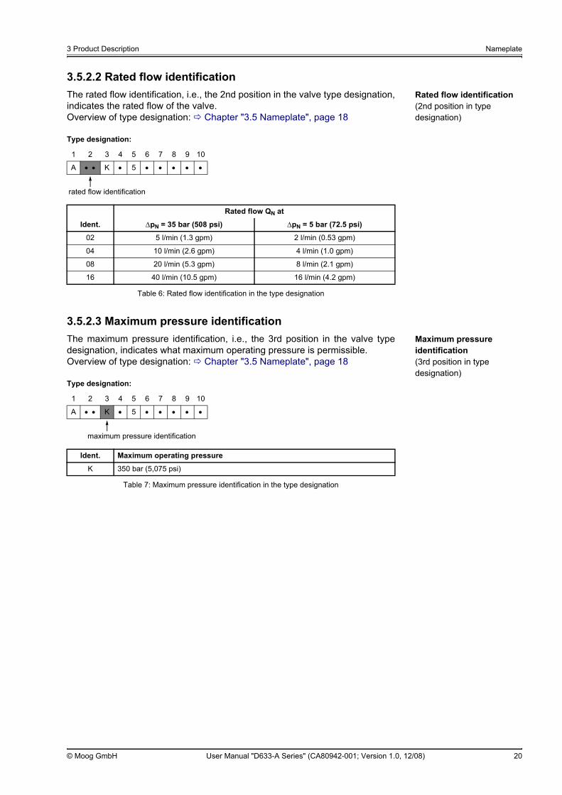
3.5.2.2 Rated flow identificationRated flow identification (2nd position in type designation)
The rated flow identification, i.e., the 2nd position in the valve type designation,indicates the rated flow of the valve.Overview of type designation: Chapter "3.5 Nameplate", page 18
3.5.2.3 Maximum pressure identificationMaximum pressure identification (3rd position in type designation)
The maximum pressure identification, i.e., the 3rd position in the valve typedesignation, indicates what maximum operating pressure is permissible.Overview of type designation: Chapter "3.5 Nameplate", page 18
Type designation:
1 2 3 4 5 6 7 8 9 10
A • • K • 5 • • • • •
Rated flow QN at
Ident. ∆pN = 35 bar (508 psi) ∆pN = 5 bar (72.5 psi)
02 5 l/min (1.3 gpm) 2 l/min (0.53 gpm)
04 10 l/min (2.6 gpm) 4 l/min (1.0 gpm)
08 20 l/min (5.3 gpm) 8 l/min (2.1 gpm)
16 40 l/min (10.5 gpm) 16 l/min (4.2 gpm)
Table 6: Rated flow identification in the type designation
rated flow identification
Type designation:
1 2 3 4 5 6 7 8 9 10
A • • K • 5 • • • • •
Ident. Maximum operating pressure
K 350 bar (5,075 psi)
Table 7: Maximum pressure identification in the type designation
maximum pressure identification

3 Product Description Nameplate
© Moog GmbH User Manual "D633-A Series" (CA80942-001; Version 1.0, 12/08) 21
3.5.2.4 Bushing-spool identificationBushing-spool identification (4th position in type designation)
The bushing-spool identification, i.e., the 4th position in the valve type designa-tion, indicates which bushing-spool version is integrated in the valve.Overview of type designation: Chapter "3.5 Nameplate", page 18
3.5.2.5 Linear force motor identificationLinear force motor identification (5th position in type designation)
The linear force motor identification, i.e., the 5th position in the valve type des-ignation, indicates which linear force motor is integrated in the valve.Overview of type designation: Chapter "3.5 Nameplate", page 18
Type designation:
1 2 3 4 5 6 7 8 9 10
A • • K • 5 • • • • •
Ident. Valve configuration Bushing-spool version
O 4-way Linear characteristic curve, zero lap
A 4-way Linear characteristic curve, ±1.5 % to ±3 % positive overlap
D 4-way Linear characteristic curve, ±10 % positive overlap
B 3-way Valve opening: P A and A T
Z 2x2-way Valve opening: P A and B T (externally connect P with B and A with T), with port Y only
X Special spool, on request
Table 8: Bushing-spool identification in the type designation
bushing-spool identification
Type designation:
1 2 3 4 5 6 7 8 9 10
A • • K • 5 • • • • •
Ident. Integrated linear force motor
5 Standard linear force motor
Table 9: Linear force motor identification in the type designation
linear force motor identification

3 Product Description Nameplate
© Moog GmbH User Manual "D633-A Series" (CA80942-001; Version 1.0, 12/08) 22
3.5.2.6 Fail-safe identificationFail-safe identification (6th position in type designation)
The fail-safe identification, i.e., the 6th position in the valve type designation,indicates which mechanical fail-safe function is integrated in the valve.Overview of type designation: Chapter "3.5 Nameplate", page 18
3.5.2.7 Y-identificationY-identification (7th position in type designation)
The Y-identification, i.e., the 7th position in the valve type designation, indi-cates how leakage port Y is configured in the valve.Overview of type designation: Chapter "3.5 Nameplate", page 18
3.5.2.8 Sealing material identificationSealing material identification (8th position in type designation)
The sealing material identification, i.e., the 8th position in the valve type desig-nation, indicates the sealing material of the port O-rings of the valve.Overview of type designation: Chapter "3.5 Nameplate", page 18
Type designation:
1 2 3 4 5 6 7 8 9 10
A • • K • 5 • • • • •
Ident. Fail-safe function Further information
F Valves with fail-safe function F Table 1, page 14Chapter "3.2.1.1 Valves with fail-safe
function F, D or M", page 14D Valves with fail-safe function D
M Valves with fail-safe function M
X Valves with special fail-safe function
Table 10: Fail-safe identification in the type designation
fail-safe identification
Type designation:
1 2 3 4 5 6 7 8 9 10
A • • K • 5 • • • • •
Ident. Leakage port Y Can be used at
0 Closed, with screw plug Pressure in tank port pT ≤ 50 bar (725 psi)
3 Open, with filter element Pressure in tank port pT > 50 bar (725 psi)
Table 11: Y-identification in the type designation
Y-identification
Type designation:
1 2 3 4 5 6 7 8 9 10
A • • K • 5 • • • • •
Ident. Sealing material
H HNBR
V FKM
E EPDM
Table 12: Sealing material identification in the type designation
sealing material identification

3 Product Description Nameplate
© Moog GmbH User Manual "D633-A Series" (CA80942-001; Version 1.0, 12/08) 23
3.5.2.9 Valve connector identificationValve version identification (9th position in type designation)
The valve connector identification, i.e., the 9th position in the valve type desig-nation, indicates which valve connector is installed to the valve.Overview of type designation: Chapter "3.5 Nameplate", page 18
3.5.2.10 Command signal identificationCommand signal identification (10th position in type designation)
The command signal identification, i.e., the 10th position in the valve type des-ignation, indicates the command signal of the valve.Overview of type designation: Chapter "3.5 Nameplate", page 18
3.5.3 Data matrix codeData matrix code The data matrix code is a two-dimensional code. The code on the nameplate
contains a character string which is set out as follows:
If there is no optional version identification, a blank space appears here.
Example: D633-184B#E#D7654
Type designation:
1 2 3 4 5 6 7 8 9 10
A • • K • 5 • • • • •
Ident. Valve connector
A 4-pin MIL connector as per MIL-DTL-5015/14S-2P
M 4-pin M12 connector as per IEC 60947-4-2
Table 13: Valve version identification in the type designation
valve connector identification
Type designation:
1 2 3 4 5 6 7 8 9 10
A • • K • 5 • • • • •
Ident. Command signal
V Iin = ±600 mA
Y Special command signal for valves with fail-safe function F and D, on request
Table 14: Command signal identification in the type designation
command signal identification
model number # optional version identification # serial number with country identification
Chapter "3.5.1 Model number", page 18
Figure 7, page 18, item 7 Figure 7, page 18, item 3

3 Product Description Nameplate
© Moog GmbH User Manual "D633-A Series" (CA80942-001; Version 1.0, 12/08) 24
For your notes.
4 Technical Data General technical data
© Moog GmbH User Manual "D633-A Series" (CA80942-001; Version 1.0, 12/08) 25
4 Technical Data
4.1 General technical data
General technical data
WARNING Observe and adhere to the technical data and in particularthe information given on the valve nameplate.
WARNING Use of the valves in potentially explosive environments isnot permitted.
CAUTION The valves must not be immersed in liquids!
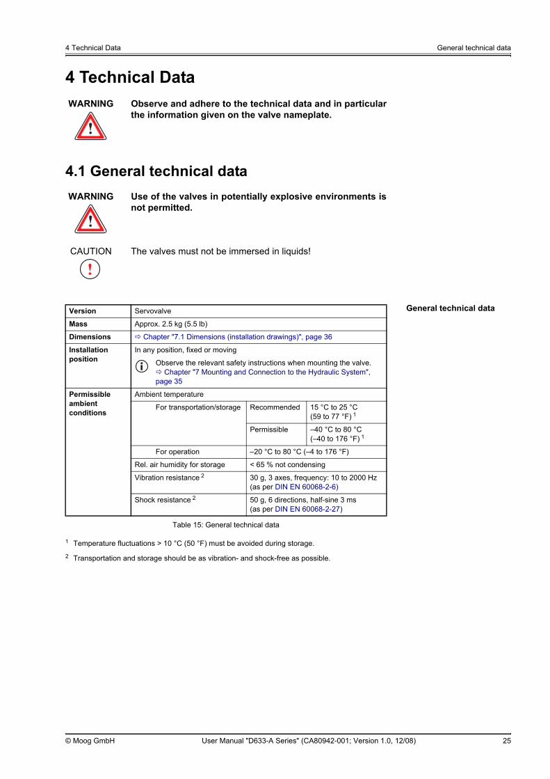
Version Servovalve
Mass Approx. 2.5 kg (5.5 lb)
Dimensions Chapter "7.1 Dimensions (installation drawings)", page 36
Installation position
In any position, fixed or moving
Observe the relevant safety instructions when mounting the valve.Chapter "7 Mounting and Connection to the Hydraulic System",
page 35
Permissible ambient conditions
Ambient temperature
For transportation/storage Recommended 15 °C to 25 °C (59 to 77 °F) 1
1 Temperature fluctuations > 10 °C (50 °F) must be avoided during storage.
Permissible –40 °C to 80 °C (–40 to 176 °F) 1
For operation –20 °C to 80 °C (–4 to 176 °F)
Rel. air humidity for storage < 65 % not condensing
Vibration resistance 2
2 Transportation and storage should be as vibration- and shock-free as possible.
30 g, 3 axes, frequency: 10 to 2000 Hz (as per DIN EN 60068-2-6)
Shock resistance 2 50 g, 6 directions, half-sine 3 ms (as per DIN EN 60068-2-27)
Table 15: General technical data

4 Technical Data Hydraulic data
© Moog GmbH User Manual "D633-A Series" (CA80942-001; Version 1.0, 12/08) 26
4.2 Hydraulic data
4.3 Static and dynamic data
Valve construction type Spool valve, one-stage, with bushing
Actuation Directly with permanent magnet linear force motor
Control oil supply None
Nominal size and mounting pattern
NG6, mounting pattern as per ISO 4401-03-03-0-05, with or without leakage port YChapter "3.3.3 Leakage port Y", page 17Chapter "7.2.2 Mounting pattern of mounting surface", page 37
Diameter of ports 7.9 mm (0.31 in)Chapter "7.2.2 Mounting pattern of mounting surface", page 37
Sealing material HNBR, FKM, EPDM, others on requestChapter "3.5.2.8 Sealing material identification", page 22
Valve configurations 2-way, 3-way, 4-way and 2x2-way operationChapter "3.3.2 Valve configurations and hydraulic symbols", page 16
Overlap Zero lap, less than ±3 % or ±10 % positive overlap (model-dependent)Chapter "3.5.2.4 Bushing-spool identification", page 21
Max. flow Qmax 75 l/min (20 gpm)Chapter "5.1 Dependency of Flow and Pressure Drop", page 29
Rated flow QN 5/10/20/40 l/min (1.3/2.6/5.3/10.5 gpm) (model-dependent) (at ∆pN = 35 bar (508 psi) per control land: tolerance ±10 %)
Chapter "3.5.2.2 Rated flow identification", page 20
Max. leakage flow QL1 0.15/0.3/0.6/1.2 l/min (0.04/0.08/0.16/0.32 gpm) (model-dependent)
Maximum operating pressure Ports P, A and B 350 bar (5,075 psi)Chapter "3.5.2.3 Maximum pressure identification", page 20
Port T without Y 50 bar (725 psi)Chapter "3.3.3 Leakage port Y", page 17
Port T with Y 350 bar (5,075 psi)
Port Y Depressurized to tank
Hydraulic fluid Permissible fluids Mineral-oil-based hydraulic oil as per DIN 51524-1 to DIN 51524-3Other fluids on request
Permissible temperature –20 to 80 °C (–4 to 176 °F)
Viscosity ν Recommended 15 to 100 mm²/s
Permissible 5 to 400 mm²/s
Cleanliness level, recommended (ISO 4406)
For functional safety < 18/15/12
For life cycle (wear and tear) < 17/14/11
The cleanliness of the hydraulic fluid greatly influences the functional safety (safe positioningof the spool, high resolution) and the wear (control lands, pressure gain, leakage losses) ofthe valves. To avoid malfunctions and increased wear, we recommend that the hydraulic fluidbe filtered accordingly.
Table 16: Hydraulic data
1 Typical values (measured at operating pressure pP = 140 bar (2,030 psi), viscosity of hydraulic fluid ν = 32 mm2/s and temperature ofhydraulic fluid T = 40 °C (104 °F))
Step response time for 0 to 100 % spool stroke 1
18 msChapter "5.5 Step response and frequency response", page 31
Hysteresis 1 Approx. 10 %
Table 17: Static and dynamic data
1 Typical values (measured at operating pressure pP = 140 bar (2,030 psi), viscosity of hydraulic fluid ν = 32 mm2/s and temperature ofhydraulic fluid T = 40 °C (104 °F))
4 Technical Data Electrical data
© Moog GmbH User Manual "D633-A Series" (CA80942-001; Version 1.0, 12/08) 27
4.4 Electrical dataElectrical data
4.5 EmissionsEnvironmental protection: Emissions
Generally speaking, the valves do not generate harmful emissions when theyare used for their intended purpose.
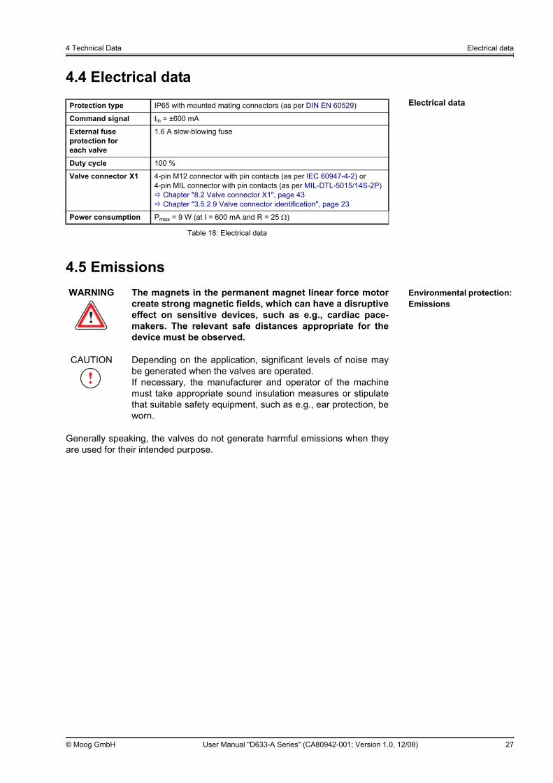
Protection type IP65 with mounted mating connectors (as per DIN EN 60529)
Command signal Iin = ±600 mA
External fuse protection for each valve
1.6 A slow-blowing fuse
Duty cycle 100 %
Valve connector X1 4-pin M12 connector with pin contacts (as per IEC 60947-4-2) or4-pin MIL connector with pin contacts (as per MIL-DTL-5015/14S-2P)
Chapter "8.2 Valve connector X1", page 43Chapter "3.5.2.9 Valve connector identification", page 23
Power consumption Pmax = 9 W (at I = 600 mA and R = 25 Ω)
Table 18: Electrical data
WARNING The magnets in the permanent magnet linear force motorcreate strong magnetic fields, which can have a disruptiveeffect on sensitive devices, such as e.g., cardiac pace-makers. The relevant safe distances appropriate for thedevice must be observed.
CAUTION Depending on the application, significant levels of noise maybe generated when the valves are operated. If necessary, the manufacturer and operator of the machinemust take appropriate sound insulation measures or stipulatethat suitable safety equipment, such as e.g., ear protection, beworn.
4 Technical Data Emissions
© Moog GmbH User Manual "D633-A Series" (CA80942-001; Version 1.0, 12/08) 28
For your notes.

5 Characteristic Curves Dependency of flow and pressure drop
© Moog GmbH User Manual "D633-A Series" (CA80942-001; Version 1.0, 12/08) 29
5 Characteristic Curves
5.1 Dependency of flow and pressure dropThe flow that is set depends not only on the spool position but also on the pres-sure difference ∆p at the individual control lands.
Formula for calculating the flow Q
A command signal of 100 % produces with a rated pressure difference of∆pN = 35 bar (508 psi) per control land the rated flow QN. If the pressure differ-ence is altered, the flow Q also changes with a constant command signal in ac-cordance with the following formula:
Chapter "3.3.1 Open-loop flow control (Q-control)", page 16
5.2 Flow signal characteristic curve 1
Flow signal characteristic curve
Q [l/min (gpm)] : actual flowQN [l/min (gpm)] : rated flow∆p [bar (psi)] : actual pressure difference per control land∆pN [bar (psi)] : rated pressure difference
∆pN = 35 bar (508 psi) per control land
Q QN∆p∆pN--------------⋅=
To avoid cavitation, the flow speed of the actual flow Q calculated in thisway at ports (A, B, P, T, etc.) must not be too great.In typical applications the maximum permissible flow speed is 30 m/s(approx. 100 ft/s).
1 Typical characteristic curves (measured at operating pressure pP = 140 bar(2,030 psi), viscosity of hydraulic fluid ν = 32 mm2/s and temperature of hy-draulic fluid T = 40 °C (104 °F))
command signal [%]
Figure 8: Flow signal characteristic curve Figure 9: Setup for measuring the flow signal characteristic curve
Q QN
------------
[%]

5 Characteristic Curves Spool stroke signal characteristic curve
© Moog GmbH User Manual "D633-A Series" (CA80942-001; Version 1.0, 12/08) 30
5.3 Spool stroke signal characteristic curve 1
Spool stroke signal characteristic curve
5.4 Pressure signal characteristic curve 1
Pressure signal characteristic curve of the valves with zero lap
1 Typical characteristic curves (measured at operating pressure pP = 140 bar(2,030 psi), viscosity of hydraulic fluid ν = 32 mm2/s and temperature of hy-draulic fluid T = 40 °C (104 °F))
Spo
ol s
troke
[%]
command signal [%]
Figure 10: Spool stroke signal characteristic curve
command signal [%]
Figure 11: Pressure signal characteristic curve of the valves with zero lap
Figure 12: Setup for measuring the pressure signal characteristic curve
∆p A
B
p P-----------------
[%]

5 Characteristic Curves Step response and frequency response
© Moog GmbH User Manual "D633-A Series" (CA80942-001; Version 1.0, 12/08) 31
5.5 Step response and frequency response 1
Step response of the spool stroke
Figure 13: Step response of the spool stroke
Frequency response of the spool stroke
Figure 14: Frequency response of the spool stroke
1 Typical characteristic curves (measured with Mini DDV Amplifier G123-821at 24 V, operating pressure pP = 140 bar (2,030 psi), viscosity of hydraulicfluid ν = 32 mm2/s and temperature of hydraulic fluid T = 40 °C (104 °F))
spoo
l stro
ke [%
]
time [ms]
ampl
itude
ratio
[dB
]
frequency [Hz]
phas
e la
g [d
egre
es]

5 Characteristic Curves Step response and frequency response
© Moog GmbH User Manual "D633-A Series" (CA80942-001; Version 1.0, 12/08) 32
For your notes.

6 Transportation and Storage
© Moog GmbH User Manual "D633-A Series" (CA80942-001; Version 1.0, 12/08) 33
6 Transportation and StorageSafety instructions: Transportation and storage
WARNING The permissible ambient conditions for the valves mustbe maintained at all times including transportation andstorage.
Chapter "4 Technical Data", page 25The valves must be protected in particular to prevent entryof dust and moisture.Fault-free, reliable and safe operation cannot be guaranteed ifthe above requirements are not observed.
WARNING The valves must not be transported or stored without theirshipping plate mounted.This is the only way of adequately protecting the valvesagainst the ingress of dirt and moisture and protecting theseals against the effects of ozone and UV.
CAUTION To provide protection against injuries or other damaging influ-ences on health, suitable protective measures must be taken ifnecessary prior to and when carrying out any work on thevalves or the machine, such as e.g., mounting or removing,electrical or hydraulic connection, troubleshooting or servicing,and when handling the valves, accessories, tools or hydraulicfluids.
Chapter "2.6 Occupational safety and health", page 9
CAUTION The valve shipping plate may only be removed from the valvehydraulic ports directly prior to mounting and must be re-mounted directly after the valve has been removed. This is theonly way of adequately protecting the valves against the in-gress of dirt and moisture and protecting the seals against theeffects of ozone and UV.The shipping plate and the associated fastening elements(screws and nuts) must be kept for later use, e.g., during trans-portation.
CAUTION Do not misuse the connectors, mating connectors (plugs) andconnection cables of the valves, e.g., as a tread or transportfixture.
CAUTION To avoid condensation after the valves have been transportedor stored, wait until they have reached the ambient tempera-ture before starting up the valves.
CAUTION To avoid damage, always transport or store valves, spare partsand accessories only in the properly sealed original packaging.Warranty and liability claims for personal injury and damage toproperty are excluded if they are caused by valves, spare partsor accessories having been stored or transported outside theiroriginal packaging.
Chapter "1.5 Warranty and liability", page 4

6 Transportation and Storage Unpacking/checking a delivery
© Moog GmbH User Manual "D633-A Series" (CA80942-001; Version 1.0, 12/08) 34
6.1 Unpacking/checking a deliveryUnpacking/checking a delivery
Procedure:
1. Check whether the packaging is damaged.
2. Remove the packaging.
3. Store the damaged packaging so that if necessary damages can beclaimed from the transport contractor.We recommend that you also keep the undamaged original packaging forlater transportation or storage operations.
4. Dispose of the packaging material no longer needed in accordance withthe relevant national waste disposal regulations and environmental pro-tection provisions.
5. Check whether the packaging contents is damaged.
6. In the event of damaged packaging or damaged contents, immediatelynotify us or the responsible supplier.
7. Check whether the delivery corresponds to the order and the deliverynote.
8. In the event of wrong or incomplete delivery, immediately notify us or theresponsible supplier.
6.2 Scope of delivery of the valveScope of delivery of the valve
The scope of delivery of the valve consists of:• Valve with mounted oilproof shipping plate at the hydraulic port• 4 O-rings ID 9.25 x Ø 1.8 [mm] (ID 0.364 x Ø 0.071 [in])
for ports A, B, P and T• 1 O-ring ID 7.65 x Ø 1.8 [mm] (ID 0.301 x Ø 0.071 [in])
for port Y
6.3 StorageEffects of long-term storage
The following effects may occur in the course of long-term storage:• Sealing materials become brittle, possibly resulting in leaks• Hydraulic fluid becomes gummy, possibly resulting in friction
In order to avoid possible resulting impairments or damage, we recommendthat the valve, after a period of storage or operation of more than 5 years, beinspected by us or one of our authorized service centers.
CAUTION After transporting or storing valves, spare parts and accesso-ries, check the original packaging and contents for possibledamage.Do not start up the system if the packaging or contents showsigns of damage. In this case, immediately notify us or the re-sponsible supplier.In the event of transportation damage, store the damagedpackaging so that if necessary damages can be claimed fromthe transport contractor.

7 Mounting and Connection to the Hydraulic System
© Moog GmbH User Manual "D633-A Series" (CA80942-001; Version 1.0, 12/08) 35
Safety instructions: Mounting and Connection to the Hydraulic System
7 Mounting and Connection to the Hydraulic SystemDANGER During operation, do not carry out any work, such as e.g.,
mounting or removal, electrical or hydraulic connection,troubleshooting or servicing, on the valves or the ma-chine.Failure to comply with this requirement results in danger dueto:
• Hydraulic fluid squirting out under pressure• Uncontrolled sequences of motions• Destruction• Malfunction
Before working on the valves or the machine, shut downand switch off the machine without fail and de-energizeand depressurize the machine.For this purpose, switch off the command signal of the valvesas well as the supply voltage of the connected peripherals,such as e.g., externally powered transducers or programmingunits.Secure the machine without fail against restarting.Examples of suitable securing measures:
• Lock the main command device and remove the key• Attach a warning sign to the master switch
DANGER Hydraulic fluid squirting out under high pressure cancause serious personal injuries, burns and fires.Depressurize all hydraulic lines and accumulators in the hy-draulic circuit before mounting or removing, electrical or hy-draulical connection, start-up, troubleshooting or servicing.
WARNING Only properly qualified and authorized users may workwith and on the valves.
Chapter "2.4 Selection and qualification of personnel", page 8
CAUTION To provide protection against injuries or other damaging influ-ences on health, suitable protective measures must be taken ifnecessary prior to and when carrying out any work on thevalves or the machine, such as e.g., mounting or removing,electrical or hydraulic connection, troubleshooting or servicing,and when handling the valves, accessories, tools or hydraulicfluids.
Chapter "2.6 Occupational safety and health", page 9

7 Mounting and Connection to the Hydraulic System Dimensions (installation drawings)
© Moog GmbH User Manual "D633-A Series" (CA80942-001; Version 1.0, 12/08) 36
7.1 Dimensions (installation drawings)
Valves with M12 connector:
Valves with MIL connector:
rem
oval
room
fo
rthe
mat
ing
conn
ecto
r
rem
oval
room
fo
rthe
mat
ing
conn
ecto
r
Item Designation Further information
1 Positioning pin Chapter "7.3 Mounting the valves", page 38
2 Grounding screw Chapter "8.3 Grounding screw", page 44
3 Installation screw or attachment screw of the shipping plate
Chapter "7.3.2 Specification for installation screws", page 38Chapter "7.2.2 Mounting pattern of mounting surface", page 37
4 Nameplate Chapter "3.5 Nameplate", page 18
Figure 15: Installation drawings for valves with M12 or MIL valve connector, dimensions in mm (inches)
Hydraulic symbols: Chapter "3.3.2 Valve configurations and hydraulic symbols", page 16Procedure for mounting the valve: Chapter "7.3.3 Procedure", page 39Position of the ports: Chapter "7.2.2 Mounting pattern of mounting surface", page 37Pin assignment of X1: Chapter "8.2 Valve connector X1", page 43

7 Mounting and Connection to the Hydraulic System Mounting surface
© Moog GmbH User Manual "D633-A Series" (CA80942-001; Version 1.0, 12/08) 37
7.2 Mounting surface
7.2.1 Surface qualityEvenness and roughness of the mounting surface
7.2.2 Mounting pattern of mounting surface
Mounting pattern of mounting surface
Figure 16: Mounting pattern of mounting surface as per ISO 4401-03-03-0-05, dimensions in mm (inches)
1 Do not drill port X as the port is not sealed on the valve side2 Bore G for positioning pin must be at least 4 mm (0.16 in) deep
If the valve is mounted on the mounting surface, it projects over themounting surface.Valve dimensions:
Chapter "7.1 Dimensions (installation drawings)", page 36
Evenness as per DIN EN ISO 1302: < 0.01 mm (0.00039 in) over 100 mm (3.94 in)
Average surface finish Ra as per DIN EN ISO 1302: < 0.8 µm (0.000030 in)
P A T B F1 F2 F3 F4 X1 Y G2
Ø 7.5(0.30)
Ø 7.5(0.30)
Ø 7.5(0.30)
Ø 7.5(0.30)
M5 M5 M5 M5 - Ø 3.3(0.13)
Ø 4.0(0.16)
x 21.5(0.85)
12.7(0.50)
21.5(0.85)
30.2(1.19)
0 40.5(1.59)
40.5(1.59)
0 - 40.5(1.59)
33(1.30)
y 25.9(1.02)
15.5(0.61)
5.1(0.20)
15.5(0.61)
0 –0.75(–0.03)
31.75(1.25)
31(1.22)
- 9.0(0.35)
31.75(1.25)

7 Mounting and Connection to the Hydraulic System Mounting the valves
© Moog GmbH User Manual "D633-A Series" (CA80942-001; Version 1.0, 12/08) 38
7.3 Mounting the valves7.3.1 Tools and materials required
Tools and materials required for mounting the valves
The following tools and materials are required for mounting the valves:• Flat-bladed screwdriver 8x1.6 [mm] and if necessary open-end
wrench WAF 8(for removing the shipping plate)
• Torque wrench for hexagon socket head cap screws WAF 4(for mounting the valve)
• Installation screwsChapter "7.3.2 Specification for installation screws", page 38
• If necessary, replacement for port O-rings to be replacedChapter "13.2 Spare parts", page 66
7.3.2 Specification for installation screws
Specification for installation screws
The installation screws and replacement O-rings are not included in thevalves’ scope of delivery. They are available as accessories.
Chapter "13.1 Accessories", page 65
Hexagon socket head cap screws as per DIN EN ISO 4762
Quality class
Number required Tightening torque
M5x55 10.9 4 6.8 Nm (5.0 lbf ft) ± 10 %
Table 19: Specification for installation screws
7 Mounting and Connection to the Hydraulic System Mounting the valves
© Moog GmbH User Manual "D633-A Series" (CA80942-001; Version 1.0, 12/08) 39
7.3.3 Procedure
Safety instructions: Mounting the valves
Procedure for mounting the valves
Procedure:
1. Clean the valve connecting surface and the mounting surface.Check and if necessary correct the evenness and roughness of themounting surface.
Chapter "7.2.1 Surface quality", page 37
2. Remove the shipping plate from the valve’s hydraulic port. The shipping plate and the associated fastening elements (screws andnuts) must be kept for later use, e.g., during transportation.
3. Check for presence, elasticity, integrity and correct seating of the O-ringsin the valve ports (A, B, P, T, etc.).If necessary, install O-rings, replace or correct the seating.
4. Paying attention to the positioning pin, place the valve on the mountingsurface and align with the mounting bores.
5. Secure the valve. To do so, tighten the installation screws (hexagonsocket head cap screws) free from distortion in diagonal sequence.Tightening torque: 6.8 Nm (5.0 lbf ft) ± 10 %
Chapter "7.3.2 Specification for installation screws", page 38
WARNING Use the installation screws specified here for mountingthe valve. The shipping plate attachment screws must notunder any circumstances be used to mount the valve. Se-cure valve mounting cannot be guaranteed in such a case.Specification for installation screws: Table 19, page 38
CAUTION The valve shipping plate may only be removed from the valvehydraulic ports directly prior to mounting and must be re-mounted directly after the valve has been removed. This is theonly way of adequately protecting the valves against the in-gress of dirt and moisture and protecting the seals against theeffects of ozone and UV.The shipping plate and the associated fastening elements(screws and nuts) must be kept for later use, e.g., during trans-portation.
CAUTION To prevent the valve from overheating, mount the valve so asto ensure adequate ventilation.Do not mount the valve directly on machine parts which are ex-posed to strong vibrations or sudden movement.On units that are moved in jerks and jolts, the movement direc-tion of the spool should not be the same as the movement di-rection of the unit.
CAUTION The valve connecting surface and the mounting surface mustbe free of residues and dirt when the valve is about to bemounted.Use a clean, soft and fluff-free cloth to clean the connectingand mounting surfaces. Do not use cleaning wool. Do not useany cleaning agents or methods which could attack the sur-faces or the O-rings mechanically or chemically.

7 Mounting and Connection to the Hydraulic System Mounting the valves
© Moog GmbH User Manual "D633-A Series" (CA80942-001; Version 1.0, 12/08) 40
For your notes.

8 Electrical Connection
© Moog GmbH User Manual "D633-A Series" (CA80942-001; Version 1.0, 12/08) 41
8 Electrical ConnectionSafety instructions: Electrical Connection
DANGER During operation, do not carry out any work, such as e.g.,mounting or removal, electrical or hydraulic connection,troubleshooting or servicing, on the valves or the ma-chine.Failure to comply with this requirement results in danger dueto:
• Hydraulic fluid squirting out under pressure• Uncontrolled sequences of motions• Destruction• Malfunction
Before working on the valves or the machine, shut downand switch off the machine without fail and de-energizeand depressurize the machine.For this purpose, switch off the command signal of the valvesas well as the supply voltage of the connected peripherals,such as e.g., externally powered transducers or programmingunits.Secure the machine without fail against restarting.Examples of suitable securing measures:
• Lock the main command device and remove the key• Attach a warning sign to the master switch
DANGER Hydraulic fluid squirting out under high pressure cancause serious personal injuries, burns and fires.Depressurize all hydraulic lines and accumulators in the hy-draulic circuit before mounting or removing, electrical or hy-draulical connection, start-up, troubleshooting or servicing.
WARNING Only properly qualified and authorized users may workwith and on the valves.
Chapter "2.4 Selection and qualification of personnel", page 8
WARNING Touching electrically live parts exposes the user/operatorto the risk of:
• Electric shock• Uncontrolled sequences of motions• Destruction• Malfunction
Touching electrically live parts must therefore be avoided!
CAUTION To provide protection against injuries or other damaging influ-ences on health, suitable protective measures must be taken ifnecessary prior to and when carrying out any work on thevalves or the machine, such as e.g., mounting or removing,electrical or hydraulic connection, troubleshooting or servicing,and when handling the valves, accessories, tools or hydraulicfluids.
Chapter "2.6 Occupational safety and health", page 9

8 Electrical Connection Wiring
© Moog GmbH User Manual "D633-A Series" (CA80942-001; Version 1.0, 12/08) 42
8.1 Wiring8.1.1 Tools and materials required
Tools and materials required for electrically connecting the valves
The following are required for electrically connecting the valves:• Mating connector of valve connector X1
(4-pin, M12 or MIL depending on model)• Connection cables for mating connector
for M12 connector as per IEC 60947-4-2: usable cable with min. Ø 4 mm (0.16 in) and max. Ø 6 mm (0.24 in)for MIL connector as per MIL-DTL-5015/14S-2P: usable cable with min. Ø 6.5 mm (0.26 in) and max. Ø 9.5 mm (0.37 in)
8.1.2 Electrical connection of the valvesProcedure for electrically connecting the valves
Procedure:
1. Conduct electrical connection in accordance with the pin assignment. Chapter "8.2 Valve connector X1", page 43
2. Establish equipotential bonding, protective grounding and shielding as per"TN 353" and "TN 494".
CAUTION Do not misuse the connectors, mating connectors (plugs) andconnection cables of the valves, e.g., as a tread or transportfixture.
CAUTION Do not lay valve connection cables in the immediate vicinity ofhigh-voltage cables or together with cables that switch induc-tive or capacitive loads.
CAUTION The insulation materials employed are designed for use in thesafety extra-low-voltage range. To comply with safety regulations requires isolation from themains as per EN 61558-1 and EN 61558-2-6 and limiting allvoltages as per EN 60204-1. We recommend using SELV/PELV power supplies for the ex-ternal valve controller.Electrical connections must be conducted in compliance withEMC requirements.
CAUTION Dirt or moisture can get into the valve through open connec-tors, i.e., if no mating connector is attached, which may resultin damage to the valve.Open connectors must be covered and sealed.
The above-mentioned connectors and cables are not included in thevalves’ scope of delivery.The mating connectors are available as accessories.
Chapter "13 Accessories and Spare Parts", page 65

8 Electrical Connection Valve connector X1
© Moog GmbH User Manual "D633-A Series" (CA80942-001; Version 1.0, 12/08) 43
8.2 Valve connector X1Mating connector of valve connector X1
8.2.1 M12 valve connector X1
M12 valve connector X1
Figure 17: M12 valve connector X1 (circuit and pin assignment)
8.2.2 MIL valve connector X1
MIL valve connector X1
Figure 18: MIL valve connector X1 (circuit and pin assignment)
The mating connector of valve connector X1 is available as accessories.Chapter "13.1 Accessories", page 65
valve
view of valve connector X1
guides for proper mating
Pin Assignment Description
1 Command signal Iin = ±600 mARin = 16 Ω at coil temperature T = 20 °C (68 °F)
2 Reference point for the command signal
3 Not assigned
4 Not assigned
CAUTION To prevent the connector from being damaged, pay attentionto the alignment of the guides for proper mating.
valve
view of valve connector X1
guides forproper mating
Pin Assignment Description
A Command signal Iin = ±600 mARin = 16 Ω at coil temperature T = 20 °C (68 °F)
B Not assigned
C Not assigned
D Reference point for the command signal

8 Electrical Connection Grounding screw
© Moog GmbH User Manual "D633-A Series" (CA80942-001; Version 1.0, 12/08) 44
8.3 Grounding screwGrounding screw
Figure 19: Grounding screw
The valve is controlled via a shielded connection cable.If the equipotential bonding current flowing over the shield of the connectioncable is too high, this may interfere with the valve or the external valve control-ler. The interference can be reduced by connecting the grounding screw withthe equipotential bonding of the system.
grounding screw

9 Start-up
© Moog GmbH User Manual "D633-A Series" (CA80942-001; Version 1.0, 12/08) 45
9 Start-upSafety instructions: Start-up
DANGER During operation, do not carry out any work, such as e.g.,mounting or removal, electrical or hydraulic connection,troubleshooting or servicing, on the valves or the ma-chine.Failure to comply with this requirement results in danger dueto:
• Hydraulic fluid squirting out under pressure• Uncontrolled sequences of motions• Destruction• Malfunction
Before working on the valves or the machine, shut downand switch off the machine without fail and de-energizeand depressurize the machine.For this purpose, switch off the command signal of the valvesas well as the supply voltage of the connected peripherals,such as e.g., externally powered transducers or programmingunits.Secure the machine without fail against restarting.Examples of suitable securing measures:
• Lock the main command device and remove the key• Attach a warning sign to the master switch
DANGER Operating machines with damaged or defective compo-nents or with a leaking hydraulic system is dangerous andnot permitted.Before starting up or operating the valve, check the higher-level machine including all of its installed components for dam-age and defects. Pay particular attention here to higher-level and hydraulicsafety devices, such as e.g., EMERGENCY STOP switchesand pressure-limiting valves.In addition, to avoid damage or leaks, perform the followingtasks at regular intervals in accordance with the instructions ofthe manufacturer and the operator of the machine:
• Checking the valve and the hydraulic system for exter-nally identifiable damage and defects.
• Checking for loose plugs/connectors.• Checking the cleanliness level of the hydraulic fluid.• Checking the port O-rings for elasticity, integrity and cor-
rect seating.Chapter "11.2.1 Checking and replacing the port
O-rings", page 58Report damage or defects to the relevant department im-mediately. If necessary, shut down and secure the ma-chine immediately. Rectify any leaks immediately in accor-dance with this user manual, paying particular attention tothe notes/instructions on handling in accordance withsafety requirements.
Chapter "2.2 Handling in accordance with safety require-ments", page 6
Chapter "11.3 Troubleshooting", page 59

9 Start-up
© Moog GmbH User Manual "D633-A Series" (CA80942-001; Version 1.0, 12/08) 46
DANGER Hydraulic fluid squirting out under high pressure cancause serious personal injuries, burns and fires.Depressurize all hydraulic lines and accumulators in the hy-draulic circuit before mounting or removing, electrical or hy-draulical connection, start-up, troubleshooting or servicing.
WARNING Only properly qualified and authorized users may workwith and on the valves.
Chapter "2.4 Selection and qualification of personnel", page 8
WARNING Excessive pressure at the hydraulic ports damages thevalve and can cause unsafe states in the machine and per-sonal injury.Pressure-limiting valves, for example, or other comparablesafety devices must be installed to limit the pressure at all ofthe hydraulic ports to the specified maximum operating pres-sure.Maximum operating pressure:
Chapter "4 Technical Data", page 25
WARNING Prior to start-up, the valves must be checked for correctmechanical design. Wrong mechanical design of thevalves will result in danger due to:
• Uncontrolled sequences of motions• Destruction• Malfunction
CAUTION The valve shipping plate may only be removed from the valvehydraulic ports directly prior to mounting and must be re-mounted directly after the valve has been removed. This is theonly way of adequately protecting the valves against the in-gress of dirt and moisture and protecting the seals against theeffects of ozone and UV.The shipping plate and the associated fastening elements(screws and nuts) must be kept for later use, e.g., during trans-portation.
CAUTION Do not misuse the connectors, mating connectors (plugs) andconnection cables of the valves, e.g., as a tread or transportfixture.
CAUTION Dirt or moisture can get into the valve through open connec-tors, i.e., if no mating connector is attached, which may resultin damage to the valve.Open connectors must be covered and sealed.
CAUTION To provide protection against injuries or other damaging influ-ences on health, suitable protective measures must be taken ifnecessary prior to and when carrying out any work on thevalves or the machine, such as e.g., mounting or removing,electrical or hydraulic connection, troubleshooting or servicing,and when handling the valves, accessories, tools or hydraulicfluids.
Chapter "2.6 Occupational safety and health", page 9

9 Start-up Preparations
© Moog GmbH User Manual "D633-A Series" (CA80942-001; Version 1.0, 12/08) 47
9.1 PreparationsPreparations for start-upThe valves may only be started up when the following is ensured:
• The higher-level machine with all of its installed components complieswith the latest versions of the relevant national and international regula-tions, standards and guidelines (such as e.g., the EU Machinery Directive,the regulations of the trade association and of TÜV or VDE).
• The valves and all of the other installed components are in a technicallyfault-free and operationally reliable state.
• No signals which can lead to uncontrolled movements in the machine aretransmitted to the valves.
Chapter "2.1 Intended operation", page 5
9.2 Start-up of the valvesProcedure for start-upProcedure:
1. Make sure that all of the machine components, connections and portsconform to the specifications of the machine manufacturer and operator.
2. Prepare the hydraulic system.Chapter "9.3 Filling and flushing the hydraulic system", page 48
3. Establish the valve hydraulic connection.Chapter "7.3 Mounting the valves", page 38
4. Establish the valve electrical connection.Chapter "8 Electrical Connection", page 41
5. Make sure that all of the mechanical, electrical and hydraulic connectionsare correctly established.
6. Start-up of the hydraulic system.Chapter "9.4 Start-up of the hydraulic system", page 49

9 Start-up Filling and flushing the hydraulic system
© Moog GmbH User Manual "D633-A Series" (CA80942-001; Version 1.0, 12/08) 48
9.3 Filling and flushing the hydraulic system
Procedure for filling and flushing the hydraulic system
Procedure:
1. Depressurize the hydraulic system.
2. Fill the hydraulic system in accordance with the instructions of the manu-facturer and the operator of the machine.Because new hydraulic fluid is contaminated, the hydraulic system mustbe filled via a filling filter with a filter fineness of at least β10 ≥ 75 (10 µm(0.00039 in) absolute).
3. Replace existing filter elements with flushing elements in accordance withthe instructions of the manufacturer and the operator of the machine.
4. Remove the servovalve.Chapter "11.1 Removing the valves", page 57
5. Instead of the servovalve, you must install a flushing plate or, if allowed bythe hydraulic system, a switching valve.
6. Carefully flush the hydraulic system in accordance with the instructions ofthe manufacturer and the operator of the machine. Observe the followingwhen doing so:
– In order to obtain the best possible flushing effect, make sure the hy-draulic fluid reaches operating temperature.
– Observe the minimum flushing time t:
– End the flushing process when at least the cleanliness level 18/15/12as specified in ISO 4406 is achieved.
7. Depressurize the hydraulic system.
8. Replace flushing elements with suitable filter elements in accordance withthe instructions of the manufacturer and the operator of the machine.
9. Remove the flushing plate or switching valve.
10. Mount the servovalve.Chapter "7.3 Mounting the valves", page 38
WARNING If a switching valve is fitted to flush the hydraulic system,this must not cause any potentially dangerous states inthe machine.
Use the flushing plate to flush lines P and T.The switching valve can also be used to flush the actuator with linesA and B.
The flushing plates are not included in the valves’ scope of delivery.They are available as accessories.
Chapter "13.1 Accessories", page 65
V [l] : tank capacityQ [l/min] : pump delivery
t 5 VQ-------- h[ ]⋅=

9 Start-up Start-up of the hydraulic system
© Moog GmbH User Manual "D633-A Series" (CA80942-001; Version 1.0, 12/08) 49
9.4 Start-up of the hydraulic systemProcedure for start-up of the hydraulic system
Procedure:
1. Start up the hydraulic system in accordance with the instructions of themanufacturer and the operator of the machine.
2. Vent the hydraulic system in accordance with the instructions of the man-ufacturer and the operator of the machine.
3. Check the hydraulic system for external leaks.
9.4.1 Venting the hydraulic system
CAUTION Air trapped in the hydraulic system, particularly in the case ofhigh pressure peaks in the system, can cause a diesel effect. Ifthe trapped air bubbles are compressed very quickly and thusheated, this can cause the mixture to self-ignite. This causes avery high increase in pressure and temperature locally, whichin turn can result in damage in the hydraulic system, e.g., toseals or components, causing the oil to age more quickly.To avoid diesel effects, it is essential to vent the hydraulic sys-tem.

9 Start-up Start-up of the hydraulic system
© Moog GmbH User Manual "D633-A Series" (CA80942-001; Version 1.0, 12/08) 50
For your notes.

10 Operation
© Moog GmbH User Manual "D633-A Series" (CA80942-001; Version 1.0, 12/08) 51
10 OperationSafety instructions: Operation
DANGER During operation, do not carry out any work, such as e.g.,mounting or removal, electrical or hydraulic connection,troubleshooting or servicing, on the valves or the ma-chine.Failure to comply with this requirement results in danger dueto:
• Hydraulic fluid squirting out under pressure• Uncontrolled sequences of motions• Destruction• Malfunction
Before working on the valves or the machine, shut downand switch off the machine without fail and de-energizeand depressurize the machine.For this purpose, switch off the command signal of the valvesas well as the supply voltage of the connected peripherals,such as e.g., externally powered transducers or programmingunits.Secure the machine without fail against restarting.Examples of suitable securing measures:
• Lock the main command device and remove the key• Attach a warning sign to the master switch
DANGER Operating machines with damaged or defective compo-nents or with a leaking hydraulic system is dangerous andnot permitted.Before starting up or operating the valve, check the higher-level machine including all of its installed components for dam-age and defects. Pay particular attention here to higher-level and hydraulicsafety devices, such as e.g., EMERGENCY STOP switchesand pressure-limiting valves.In addition, to avoid damage or leaks, perform the followingtasks at regular intervals in accordance with the instructions ofthe manufacturer and the operator of the machine:
• Checking the valve and the hydraulic system for exter-nally identifiable damage and defects.
• Checking for loose plugs/connectors.• Checking the cleanliness level of the hydraulic fluid.• Checking the port O-rings for elasticity, integrity and cor-
rect seating.Chapter "11.2.1 Checking and replacing the port
O-rings", page 58Report damage or defects to the relevant department im-mediately. If necessary, shut down and secure the ma-chine immediately. Rectify any leaks immediately in accor-dance with this user manual, paying particular attention tothe notes/instructions on handling in accordance withsafety requirements.
Chapter "2.2 Handling in accordance with safety require-ments", page 6
Chapter "11.3 Troubleshooting", page 59

10 Operation Preparations for operation
© Moog GmbH User Manual "D633-A Series" (CA80942-001; Version 1.0, 12/08) 52
10.1 Preparations for operationPreparations for valve operation
The valves may only be operated as a component part of a higher-level overallsystem, for example in a machine.
Chapter "2.1 Intended operation", page 5
The following must be completed before the valve is operated:• Qualified project planning• Correct start-up and configuration of the valve
Chapter "9 Start-up", page 45
WARNING Only properly qualified and authorized users may workwith and on the valves.
Chapter "2.4 Selection and qualification of personnel", page 8
WARNING Observe and adhere to the technical data and in particularthe information given on the valve nameplate.
Chapter "4 Technical Data", page 25
WARNING Prior to start-up, the valves must be checked for correctmechanical design. Wrong mechanical design of thevalves will result in danger due to:
• Uncontrolled sequences of motions• Destruction• Malfunction
CAUTION To provide protection against injuries or other damaging influ-ences on health, suitable protective measures must be taken ifnecessary prior to and when carrying out any work on thevalves or the machine, such as e.g., mounting or removing,electrical or hydraulic connection, troubleshooting or servicing,and when handling the valves, accessories, tools or hydraulicfluids.
Chapter "2.6 Occupational safety and health", page 9
CAUTION Dirt or moisture can get into the valve through open connec-tors, i.e., if no mating connector is attached, which may resultin damage to the valve.Open connectors must be covered and sealed.

10 Operation Operation of the valve
© Moog GmbH User Manual "D633-A Series" (CA80942-001; Version 1.0, 12/08) 53
10.2 Operation of the valveOperation of the valve: Via command signal from the machine controller
The valve is controlled via the command signal which it receives from the ma-chine controller.Direct interventions by the user on the valve during normal operation arenot necessary.The valve has no controls, such as e.g., switches or buttons, which must be ac-tuated.
Information on maintenance:Chapter "11.2 Maintenance", page 58
Information on correcting possible faults:Chapter "11.3 Troubleshooting", page 59
10.3 Shutting down the valveSafety instructions: Shutting down the valve
Shutting down the valveThe valve can be shut down by switching off the command signal.If necessary, the valve can be restarted by switching on the command signal.
Chapter "3.2.2 Restarting the valve", page 15
DANGER Hydraulic pressure and electrical supply voltage are stillnormally applied after the valve has been shut down. Themachine is not automatically put out of operation whenthe valve is shut down.During operation, do not carry out any work, such as e.g.,mounting or removal, electrical or hydraulic connection,troubleshooting or servicing, on the valves or the ma-chine.Failure to comply with this requirement results in danger dueto:
• Hydraulic fluid squirting out under pressure• Uncontrolled sequences of motions• Destruction• Malfunction
Before working on the valves or the machine, shut downand switch off the machine without fail and de-energizeand depressurize the machine.For this purpose, switch off the command signal of the valvesas well as the supply voltage of the connected peripherals,such as e.g., externally powered transducers or programmingunits.Secure the machine without fail against restarting.Examples of suitable securing measures:
• Lock the main command device and remove the key• Attach a warning sign to the master switch

10 Operation Shutting down the valve
© Moog GmbH User Manual "D633-A Series" (CA80942-001; Version 1.0, 12/08) 54
For your notes.

11 Service
© Moog GmbH User Manual "D633-A Series" (CA80942-001; Version 1.0, 12/08) 55
11 ServiceSafety instructions: Service
DANGER During operation, do not carry out any work, such as e.g.,mounting or removal, electrical or hydraulic connection,troubleshooting or servicing, on the valves or the ma-chine.Failure to comply with this requirement results in danger dueto:
• Hydraulic fluid squirting out under pressure• Uncontrolled sequences of motions• Destruction• Malfunction
Before working on the valves or the machine, shut downand switch off the machine without fail and de-energizeand depressurize the machine.For this purpose, switch off the command signal of the valvesas well as the supply voltage of the connected peripherals,such as e.g., externally powered transducers or programmingunits.Secure the machine without fail against restarting.Examples of suitable securing measures:
• Lock the main command device and remove the key• Attach a warning sign to the master switch
DANGER Operating machines with damaged or defective compo-nents or with a leaking hydraulic system is dangerous andnot permitted.Before starting up or operating the valve, check the higher-level machine including all of its installed components for dam-age and defects. Pay particular attention here to higher-level and hydraulicsafety devices, such as e.g., EMERGENCY STOP switchesand pressure-limiting valves.In addition, to avoid damage or leaks, perform the followingtasks at regular intervals in accordance with the instructions ofthe manufacturer and the operator of the machine:
• Checking the valve and the hydraulic system for exter-nally identifiable damage and defects.
• Checking for loose plugs/connectors.• Checking the cleanliness level of the hydraulic fluid.• Checking the port O-rings for elasticity, integrity and cor-
rect seating.Chapter "11.2.1 Checking and replacing the port
O-rings", page 58Report damage or defects to the relevant department im-mediately. If necessary, shut down and secure the ma-chine immediately. Rectify any leaks immediately in accor-dance with this user manual, paying particular attention tothe notes/instructions on handling in accordance withsafety requirements.
Chapter "2.2 Handling in accordance with safety require-ments", page 6
Chapter "11.3 Troubleshooting", page 59

11 Service
© Moog GmbH User Manual "D633-A Series" (CA80942-001; Version 1.0, 12/08) 56
DANGER Hydraulic fluid squirting out under high pressure cancause serious personal injuries, burns and fires.Depressurize all hydraulic lines and accumulators in the hy-draulic circuit before mounting or removing, electrical or hy-draulical connection, start-up, troubleshooting or servicing.
WARNING Only properly qualified and authorized users may workwith and on the valves.
Chapter "2.4 Selection and qualification of personnel", page 8
WARNING In the interests of avoiding damage to the valves or acces-sories, repairs/corrective maintenance and other mainte-nance/servicing work explained in this user manual, onaccount of the complexity of the internal components ofthe valves or accessories, may only be carried out by usor by our authorized service centers.Warranty and liability claims for personal injury and damage toproperty are excluded among other things if they are causedby unauthorized repairs or other unauthorized interventions.
Chapter "1.5 Warranty and liability", page 4
CAUTION To provide protection against injuries or other damaging influ-ences on health, suitable protective measures must be taken ifnecessary prior to and when carrying out any work on thevalves or the machine, such as e.g., mounting or removing,electrical or hydraulic connection, troubleshooting or servicing,and when handling the valves, accessories, tools or hydraulicfluids.
Chapter "2.6 Occupational safety and health", page 9
CAUTION Unsuitable or defective accessories or unsuitable or defectivespare parts may cause damage, malfunctions or failure of thevalve or the machine.We recommend the use of original accessories and originalspare parts.Warranty and liability claims for personal injury and damage toproperty are among other things excluded if they are causedby the use of unsuitable or defective accessories or unsuitableor defective spare parts.
Chapter "1.5 Warranty and liability", page 4Chapter "13 Accessories and Spare Parts", page 65
CAUTION Do not misuse the connectors, mating connectors (plugs) andconnection cables of the valves, e.g., as a tread or transportfixture.

11 Service Removing the valves
© Moog GmbH User Manual "D633-A Series" (CA80942-001; Version 1.0, 12/08) 57
11.1 Removing the valves11.1.1 Tools and materials required
Tools and materials required for removing
The following tools and materials are required for removing the valves:• Torque wrench for hexagon socket head cap screws WAF 4
(for removing and mounting the valve)• If necessary, replacement for port O-rings to be replaced
Chapter "13.2 Spare parts", page 66• Shipping plate and associated fastening elements• Flat-bladed screwdriver 8x1.6 [mm] and if necessary open-end
wrench WAF 8(for mounting the shipping plate)
11.1.2 Procedure
Safety instructions: Removing the valves
Procedure for removing the valve
Procedure:
1. Shut down and switch off the machine and place in a de-energized anddepressurized state.
2. Release the valve’s installation screws.
3. Remove the valve from the mounting surface.
4. Check for presence, elasticity, integrity and correct seating of the O-ringsin the valve ports (A, B, P, T, etc.).
5. Replace hardened and damaged O-rings with new O-rings.
6. Mount the shipping plate to the valve’s hydraulic ports.Tightening torque of the attachment screws: approx. 5 Nm (3.7 lbf ft) (hand-tight)
7. If the valve is not to be immediately reused or is to be serviced: Store thevalve in its original packaging.
Chapter "6 Transportation and Storage", page 33
8. If necessary, block the ports of the hydraulic system to prevent the hy-draulic fluid from being contaminated.
CAUTION The valve shipping plate may only be removed from the valvehydraulic ports directly prior to mounting and must be re-mounted directly after the valve has been removed. This is theonly way of adequately protecting the valves against the in-gress of dirt and moisture and protecting the seals against theeffects of ozone and UV.The shipping plate and the associated fastening elements(screws and nuts) must be kept for later use, e.g., during trans-portation.

11 Service Maintenance
© Moog GmbH User Manual "D633-A Series" (CA80942-001; Version 1.0, 12/08) 58
11.2 MaintenanceEmbrittlement of the sealing materials
Changes in temperature, effects of the hydraulic fluid, such as e.g., pressurepeaks, and similar influences can, depending on the application, expose thesealing materials to different levels of wear. This in turn may cause leaks.
In order to avoid possible resulting impairments or damage, we recommendthat the valve, after a period of storage or operation of more than 5 years, beinspected by us or one of our authorized service centers.
11.2.1 Checking and replacing the port O-rings11.2.1.1 Tools and materials required
Tools and materials required for checking and replacing the O-rings
The following are required for checking and replacing the port O-rings:• Torque wrench for hexagon socket head cap screws WAF 4
(for removing and mounting the valve)• If necessary, replacement for port O-rings to be replaced
Chapter "13.2 Spare parts", page 66
11.2.1.2 Checking and replacing the O-ringsProcedure for checking and replacing the O-rings
Procedure:
1. Remove the valve.Chapter "11.1 Removing the valves", page 57
2. Check for presence, elasticity, integrity and correct seating of the O-ringsin the valve ports (A, B, P, T, etc.).
3. Replace hardened and damaged O-rings with new O-rings.
4. Remount the valve.Chapter "7.3 Mounting the valves", page 38
If the valve is exposed to high loads, it may be necessary to reduce thecheck/inspection interval to suit the application.

11 Service Troubleshooting
© Moog GmbH User Manual "D633-A Series" (CA80942-001; Version 1.0, 12/08) 59
11.3 TroubleshootingPossible faults The following faults may occur:
• Leak at the valve connecting surfaceChapter "11.3.1.1 Leak at the valve connecting surface", page 59
• Leak at the linear force motor screw plugChapter "11.3.1.2 Leak at the linear force motor screw plug", page 59
• No hydraulic response by the valveChapter "11.3.2 No hydraulic response by the valve", page 60
• Instability of the external control loopChapter "11.3.3 Instability of the external control loop", page 60
Restarting after correcting the fault
After correcting the fault, if necessary remount and restart the valve.Chapter "7.3 Mounting the valves", page 38Chapter "3.2.2 Restarting the valve", page 15
11.3.1 Leaks11.3.1.1 Leak at the valve connecting surface
Leak at the valve connecting surface
Measures:• Check for presence, elasticity, integrity and correct seating of the O-rings
in the valve ports (A, B, P, T, etc.).If necessary, install O-rings, replace or correct the seating.
• Check the valve’s mounting and connecting surfaces, the valve and thehydraulic system for damage, contamination and evenness.
• Check installation screws for secure and correct seating.Retighten screws if necessary with the torque wrench for WAF 4 hexagonsocket head cap screws.Tightening torque of installation screws: 6.8 Nm (5.0 lbf ft) ± 10 %
11.3.1.2 Leak at the linear force motor screw plug
Leak at the linear force motor screw plug
Measures:• Check ports P and T for correct connection.• Check max. pressure in ports T and Y.
The return pressure in T may exceed 50 bar (725 psi) only if port Y isused.
If the fault cannot be corrected by means of the measures set out below,please contact us or one of our authorized service centers.
WARNING In the event of a leak at the linear force motor screw plug,have the valve checked by us or one of our authorized ser-vice centers.

11 Service Troubleshooting
© Moog GmbH User Manual "D633-A Series" (CA80942-001; Version 1.0, 12/08) 60
11.3.2 No hydraulic response by the valve
No hydraulic response by the valve
Measures:• Check whether all the machine components, connections and ports con-
form to the specifications of the machine manufacturer and operator.To do so, on the valves compare the data on the nameplate with the spec-ifications.
• Check whether the hydraulic installation is correct and whether all the hy-draulic ports are correctly established.
• Check whether the hydraulic pressure is present.• Check whether the connector is correctly attached and non-corroded.• Check whether there is a command signal failure or a faulty electric cable.• Check whether the desired command signal is applied at the connector.• Check whether the valve is in the fault state.
If necessary, correct the fault and then restart the valve by switching thecommand signal off and then on again.
Typical fault causes:– Control error (e.g., due to the spool sticking, which can be caused for
instance by contamination)– No command signal (e.g., due to open circuit)
11.3.3 Instability of the external control loopInstability of the external control loop
Measures:• Check whether the external control loop is stable.
If necessary, reduce control loop gain.• Check whether the signal quality of the command signal is sufficient.• Check whether the system pressure is stable.• Check whether the quality and cleanliness level of the hydraulic fluid used
conforms to the specifications of the manufacturer and the operator of themachine.
• Check whether the controlled system was modified.
WARNING Touching electrically live parts exposes the user/operatorto the risk of:
• Electric shock• Uncontrolled sequences of motions• Destruction• Malfunction
Touching electrically live parts must therefore be avoided!
11 Service Repair
© Moog GmbH User Manual "D633-A Series" (CA80942-001; Version 1.0, 12/08) 61
11.4 RepairAuthentic Moog repairs Authentic Moog repairs are performed exclusively by us or our authorized
service centers. This is the only way of accessing the latest specifications re-quired for repair work. With these specifications, the original valve performancedata can be re-established and the customarily high reliability and long life cy-cle can be guaranteed even after repairs.
Repair quality seal
Figure 20: Repair quality seal
Our repair seal is a guarantee that an authentic Moog repair has been per-formed.
11.4.1 Contact persons for repairsContact persons for repairs
Please refer to the following page on our internet site for contact information re-lating to our service centers:
http://www.moog.com/industrial/globallocator
In the event of a repair job for defective valves, we and our authorized ser-vice centers reserve the right to perform a repair or, after consultation, al-ternatively to supply replacement valves with an identical or compatibleequipment specification.
11 Service Repair
© Moog GmbH User Manual "D633-A Series" (CA80942-001; Version 1.0, 12/08) 62
For your notes.

12 Disposal
© Moog GmbH User Manual "D633-A Series" (CA80942-001; Version 1.0, 12/08) 63
12 Disposal
Environmental protection: Disposal
It is essential to comply with the relevant national waste disposal regulationsand environmental protection provisions when disposing of valves, spare partsor accessories, packaging that is no longer needed, hydraulic fluid or auxiliarymaterials and substances used for cleaning!If necessary, the items to be disposed of must be expertly dismantled into indi-vidual parts, separated into individual materials and placed in the correspond-ing waste system or earmarked for recycling.
The valve contains among others the following materials:• Adhesives and casting compounds• Parts with electro-plated surfaces• Permanent-magnet materials• Hydraulic fluid• Assorted metals and plastics
CAUTION To provide protection against injuries or other damaging influ-ences on health, suitable protective measures must be taken ifnecessary prior to and when carrying out any work on thevalves or the machine, such as e.g., mounting or removing,electrical or hydraulic connection, troubleshooting or servicing,and when handling the valves, accessories, tools or hydraulicfluids.
Chapter "2.6 Occupational safety and health", page 9

12 Disposal
© Moog GmbH User Manual "D633-A Series" (CA80942-001; Version 1.0, 12/08) 64
For your notes.

13 Accessories and Spare Parts Accessories
© Moog GmbH User Manual "D633-A Series" (CA80942-001; Version 1.0, 12/08) 65
13 Accessories and Spare Parts
13.1 Accessories
CAUTION Unsuitable or defective accessories or unsuitable or defective spare parts may cause dam-age, malfunctions or failure of the valve or the machine.We recommend the use of original accessories and original spare parts.Warranty and liability claims for personal injury and damage to property are among otherthings excluded if they are caused by the use of unsuitable or defective accessories or unsuit-able or defective spare parts.
Chapter "1.5 Warranty and liability", page 4
The accessories are not included in the valves’ scope of delivery.Chapter "6.2 Scope of delivery of the valve", page 34
Item designationNumber required Description Order number
Service sealing kit (contains all the O-rings for ports A, B, P, T and Y)
11
Kit HNBR 90 ShoreKit FKM 90 Shore
B97215-H630F63B97215-V630F63
Flushing plate for ports P, T, X, Y 1 B46634-002
Connecting plates On request
Installation screws 4 M5x55hexagon socket head cap screw as per DIN EN ISO 4762, quality class: 10.9, tightening torque: 6.8 Nm (5.0 lbf ft) ± 10 %
A03665-050-055
Mating connector (metal), IP65
for M12 valve connector X1 1 As per IEC 60947-4-2,usable cable with min. Ø 4 mm (0.16 in) and max. Ø 6 mm (0.24 in)
B97183-004
for 4-pin MIL valve connector X1 1 As per MIL-DTL-5015/14S-2P,usable cable with min. Ø 6.5 mm (0.26 in) and max. Ø 9.5 mm (0.37 in)
B46744-004
Supplementing documents
User manual "D633-A series", English
1 CA80942-001
Application notes "Technical Note TN 353", English
1 Protective grounding and electrical shield-ing of hydraulic valves with integrated electronics
CA58437-001
Application notes "Technical Note TN 353", German
1 Protective grounding and electrical shield-ing of hydraulic valves with integrated electronics
CA58437-002
Application notes "Technical Note TN 494", English
1 Maximum permissible lengths of electric cables for the connection of hydraulic valves with integrated electronics
CA48851-001
Application notes "Technical Note TN 494", German
1 Maximum permissible lengths of electric cables for the connection of hydraulic valves with integrated electronics
CA48851-002
Table 20: Accessories
The PDF files of the supplementing documents can be downloaded from the following link:http://www.moog.com/Industrial/Literature

13 Accessories and Spare Parts Spare parts
© Moog GmbH User Manual "D633-A Series" (CA80942-001; Version 1.0, 12/08) 66
13.2 Spare parts
Item designationNumber required Description Order number
O-rings
for ports A, B, P and T 4 ID 9.25 x Ø 1.8 [mm] (ID 0.364 x Ø 0.071 [in])
HNBR 90 ShoreFKM 90 Shore
B97009-013-42082-013
for port Y 1 ID 7.65 x Ø 1.8 [mm] (ID 0.301 x Ø 0.071 [in])
HNBR 90 ShoreFKM 90 Shore
B97009-012-42082-012
Shipping plate 1 B46035-001
Fastening elements for shipping plate Do not use to mount the valve!
Attachment screws min. 2 M5x55, slotted fillister head screw, tightening torque: approx. 5 Nm (3.7 lbf ft) (hand-tight)
-66119-050-055
Fastening nuts min. 2 M5, hexagon nut -66118-050
Table 21: Spare parts

14 Index A…C
© Moog GmbH User Manual "D633-A Series" (CA80942-001; Version 1.0, 12/08) 67
A B C D E F G H I J K L M N O P Q R S T U V W X Y Z
A B C D E F G H I J K L M N O P Q R S T U V W X Y Z
14 Indexβx (symbol for filter fineness), see Filter fineness∆p (symbol for pressure difference), see Pressure difference∆pN (symbol for rated pressure difference),
see Rated pressure differenceν (symbol for viscosity), see Viscosity2x2-Way operation, see Valve configurations2-Way operation, see Valve configurations3-Way operation, see Valve configurations4-Way operation, see Valve configurations
AA (control port), see PortsAbbreviations
list of abbreviations • 75DDV (Direct Drive Valve)DIN (Deutsches Institut für Normung e. V.,
German institute for standardization)EMC (electromagnetic compatibility)EN (Europa-Norm, European standard)EPDM (ethylene propylene diene M-class rubber,
material for seals, such as O-rings)EU (European Union)FKM (fluorocarbon rubber,
material for seals, such as O-rings)HNBR (hydrogenated nitrile butadiene rubber,
material for seals, such as O-rings)ID (inner diameter, e.g., on O-rings)IEC (International Electrotechnical Commission)IP (international protection)ISO (International Organization for Standardization)MIL (military, e.g., in MIL-STD; military standards, which are
created by the U.S. Department of Defense)NG (Nenngröße, nominal size of the valve)PELV (protective extra-low voltage)SELV (safety extra-low voltage)TN (Technical Note)TÜV (Technischer Überwachungsverein,
German technical inspection agency)UV (ultraviolet)VDE (Verband der Elektrotechnik Elektronik
Informationstechnik e. V., German association of electrical engineering, electronics and information technology)
VDI (Verein Deutscher Ingenieure e. V., association of German engineers)
WAF (width across flats for wrenches)Accessories, ordering information • 65Acronyms • 75Activation • 18Address of Moog GmbH • AAir humidity, permissible relative air humidity for storage • 25Ambient conditions
permissible ambient conditions • 25potentially explosive environment • 5, 25
Ambient temperature, permissible ambient temperature • 25Armature of the linear force motor,
in the representative depiction • 12Attachment screws of the shipping plate • 39, 57
fastening nuts, ordering information • 66in the installation drawing of the valve • 36ordering information • 66position of bores F1…F4 in the mounting surface mounting
pattern • 37tightening torque • 57width across flats • 38, 57
BB (control port), see PortsBushing in the representative depiction of the valve • 11Bushing-spool identification in the type designation
(4th position in the type designation) • 15, 21
CCavitation • 29Centering springs of the linear force motor
in the representative depiction • 12Characteristic curves • 29–31
flow signal characteristic curve • 29frequency response of the spool stroke • 31pressure signal characteristic curve • 30spool stroke signal characteristic curve • 30step response of the spool stroke • 31
Cleaningcleaning connecting and mounting surfaces • 39disposal of auxiliary materials and substances used • 63
Cleanliness level of the hydraulic fluid • 26, 48Coding pin, see Positioning pinCommand input, see Command signalCommand signal • 12, 18, 27, 43
command signal identification in the type designation (10th position in the type designation) • 23
failure of the command signal • 13restarting the valve afterwards • 15
on the nameplate • 18Command signal identification in the type designation
(10th position in the type designation) • 23Compatibility, electromagnetic (EMC), see EMCConnecting plates • 65Connecting surface
cleaning • 39troubleshooting in the event of a leak • 59
Connection of the valveselectrical connection • 41–42hydraulic connection • 35, 39

14 Index D…G
© Moog GmbH User Manual "D633-A Series" (CA80942-001; Version 1.0, 12/08) 68
A B C D E F G H I J K L M N O P Q R S T U V W X Y Z
A B C D E F G H I J K L M N O P Q R S T U V W X Y Z
Connector X1 (valve connector) • 18, 27command signal • 12guides for proper mating • 43in the representative depiction of the valve • 11mating connector • 43
ordering information • 65removal room • 36
pin assignment • 43valve connector identification (9th position in the type
designation) • 23Control loop, troubleshooting in the event of instability of the
external control loop • 60Control oil supply • 26Control port A, see PortsControl port B, see PortsCopyright of the user manual • ACorrective maintenance, see RepairCurrent input, see Command signalCurves, see Characteristic curvesCutaway drawings, see Representative depictionsCutaway views, see Representative depictions
DData matrix code
example • 23on the nameplate • 18structure of the data matrix code • 23
Date of manufacture on the nameplate • 18DDV (Direct Drive Valve) • 11Diagrams, see Characteristic curvesDiesel effect • 49Dimensions • 36DIN (Deutsches Institut für Normung e. V.,
German institute for standardization), see StandardsDirectives, overview of quoted directives • 78Disposal • 63Documents, supplementing • 2
ordering information • 65Duty cycle • 27Dynamic data • 26
EElectrical connection • 41–42Electrical data • 27Electromagnetic compatibility (EMC), see EMCEmbrittlement of seals • 34, 58EMC • 4, 7, 42Emissions • 27EN (Europa-Norm, European standard), see StandardsEnvironmental protection
disposal • 63emissions • 27
EPDM (ethylene propylene diene M-class rubber) • 22, 26EU (European Union)Evenness, required for mounting surface • 37Exclusion of liability • 4Exclusion of warranty • 4Explosive environment, potentially explosive environment •
5, 25
FF1…F4 (position of the bores for installation screws or
attachment screws of the shipping plate in the mounting surface mounting pattern) • 37
Fail-safe eventsfailure of the command signal • 13restarting the valve
after the occurrence of a fail-safe event • 15Fail-safe functions, mechanical • 13Fail-safe identification, in the type designation (6th position in
the type designation) • 14, 22Fail-safe state, mechanical fail-safe state • 13–14Failure elimination, see TroubleshootingFilling filter for the hydraulic system
required filter fineness βx • 48Filling the hydraulic system • 48Filter, filling filter for the hydraulic system
required filter fineness βx • 48Filter fineness βx
filling filter for the hydraulic system • 48FKM (fluorocarbon rubber) • 22, 26, 66Flow Q
flow signal characteristic curve • 29formula for calculation • 29leakage flow QL • 26maximum flow Qmax • 26rated flow QN • 26
rated flow identification in the type designation (2nd position in the type designation) • 20
Flow control (Q-control) • 16Flow signal characteristic curve • 29Flow speed • 29Flushing plate
ordering information • 65using when flushing the hydraulic system • 48
Flushing the hydraulic system • 48Formulas
flow Q • 29minimum flushing time t of a hydraulic system • 48
Frequency response of the spool stroke • 31Function
linear force motor • 12valve • 11
Fuse protection, external fuse protection for each valve • 27
GG (bore for positioning pin in the mounting surface mounting
pattern) • 37Gaskets, see O-ringsGrounding screw • 44
in the installation drawing • 36in the representative depiction of the valve • 11
Grounding, protective grounding • 2, 42Guides for proper mating (valve connector X1) • 43Gumming of hydraulic fluid during long-term storage • 34

14 Index H…M
© Moog GmbH User Manual "D633-A Series" (CA80942-001; Version 1.0, 12/08) 69
A B C D E F G H I J K L M N O P Q R S T U V W X Y Z
A B C D E F G H I J K L M N O P Q R S T U V W X Y Z
HHandling in accordance with safety requirements • 6HNBR (hydrogenated nitrile butadiene rubber) • 22, 26, 66Hydraulic data • 26Hydraulic fluid
cleanliness level • 26, 48diesel effect • 49disposal • 63gumming during long-term storage • 34permissible fluids • 26permissible temperature range • 26permissible viscosity ν • 26required filter fineness βx for the filling filter for the hydraulic
system • 48Hydraulic oil, see Hydraulic fluidHydraulic symbols • 16–17
2x2-way operation • 172-way operation • 173-way operation • 164-way operation • 16on the nameplate • 18
Hydraulic systemconnection of the valve to the hydraulic system • 35, 39filling and flushing • 48
minimum flushing time • 48required filter fineness βx for the filling filter • 48
preparing • 48start-up • 48–49venting • 49
Hysteresis • 26
IIin (symbol for input current), see Input currentID (inner diameter, e.g., on O-rings)IEC (International Electrotechnical Commission), see StandardsInput current Iin • 43Input resistance Rin • 43Instability of the external control loop, troubleshooting • 60Installation drawing, see DimensionsInstallation position • 25Installation screws
in the installation drawing of the valve • 36ordering information • 65position of bores F1…F4 in the mounting surface mounting
pattern • 37required quality class • 38specification • 38tightening torque • 38width across flats • 38, 57
Intended operation of the valves • 5Intended use of the valves • 5Interfaces, see Signal interfaceIP (international protection), see Protection type by enclosureISO (International Organization for Standardization),
see StandardsItem numbers, see Order numbers
LLeakage flow QL • 26Leakage port Y, see PortsLeakage, troubleshooting
connecting surface of the valve • 59linear force motor screw plug • 59
Linear force motor • 12armature • 12bearing • 12centering springs • 12coil • 12cutaway drawing • 12cutaway view • 12linear force motor identification, in the type designation
(5th position in the type designation) • 21permanent magnets • 12representative depiction • 12screw plug • 12
troubleshooting in the event of a leak • 59List of figures • viList of tables • vLiterature, additional
directives, quoted • 78Moog publications • 77standards, quoted • 77–78supplementing documents • 2
Locating pin, see Positioning pin
MMaintenance • 55–56
O-ring checking and replacement • 58Manufacturer’s address • AManufacturer’s declaration • 3Mass, in kg (lb) • 25Mating connector for valve connector X1 • 43
ordering information • 65removal room • 36
Maximum pressure identification, in the type designation (3rd position in the type designation) • 20
MIL (Military, e.g., in MIL-STD; military standards, which are created by the U.S. Department of Defense), see Standards
Minimum flushing time for flushing the hydraulic system • 48Mode of operation
linear force motor • 12valve • 11
Model numberexample • 18on the nameplate • 18structure of the model number • 18
Modifications, see Structural modificationsMounting • 35, 39
installation position • 25mounting option • 25procedure • 39tools and materials required • 38
Mounting option • 25Mounting pattern of mounting surface • 26, 37Mounting surface • 37
cleaning • 39mounting pattern • 26, 37permissible average roughness Ra • 37required evenness • 37

14 Index N…Q
© Moog GmbH User Manual "D633-A Series" (CA80942-001; Version 1.0, 12/08) 70
A B C D E F G H I J K L M N O P Q R S T U V W X Y Z
A B C D E F G H I J K L M N O P Q R S T U V W X Y Z
Nn (symbol for number)Nameplate • 18
in the installation drawing of the valve • 36NG (Nenngröße, nominal size) • 26Nominal size (NG, Nenngröße) • 26
OOccupational safety and health
safe distances for cardiac pacemakers and similar devices due to magnetic fields • 9, 27
safety equipment • 9, 33, 35, 41, 46, 52, 56, 63sound insulation measures • 9, 27
Oil, see Hydraulic fluidOperating pressure pP
maximum operating pressure • 20, 26maximum operating pressure on the nameplate • 18
Operation of the valves • 51–53ambient conditions, permissible • 25intended operation • 5necessary preparations • 52
Operational mode • 16flow control, see Flow controlQ-control, see Flow control
Order numbers • 65–66Ordering information, see Order numbersOriginal packaging, see PackagingO-rings
checking and replacing the port O-rings • 58cleaning • 39embrittlement • 34, 58ordering information • 66permissible materials • 26protection against the effects of ozone and UV
by shipping plate • 33, 39, 46, 57sealing material identification, in the type designation
(8th position in the type designation) • 22service sealing kit, ordering information • 65specification • 66
Overlap • 16, 26
PP (pressure port), see PortsPmax (symbol for power consumption at maximum flow),
see Power consumptionp (symbol for pressure), see Pressure∆p (symbol for pressure difference), see Pressure difference∆pN (symbol for rated pressure difference),
see Rated pressure differencepP (symbol for operating pressure), see Operating pressurePackaging
disposal • 63storing original packaging • 33–34
Part numbers, see Order numbersPELV (protective extra-low voltage),
see SELV/PELV power supplyPermanent magnet linear force motor, see Linear force motorPermanent magnets of the linear force motor
in the representative depiction • 12Personnel, selection and qualification of personnel • 8Pin assignment of the valve connector X1 • 43Ports
diameter of ports • 26, 37in the representative depiction of the valve • 11leakage port Y • 17
Y-identification in the type designation (7th position in the type designation) • 17, 22
on the nameplate • 18O-ring checking and replacement • 58position of the ports in the mounting surface mounting
pattern • 37troubleshooting in the event of leaks • 59
Positioning pinbore G in the mounting surface mounting pattern • 37in the installation drawing • 36
Power consumption Pmax • 27Power pack, see SELV/PELV power supplyPower supply of external valve controller
SELV/PELV power supply • 42Pressure p
operating pressure pP, see Operating pressurepressure difference ∆p, see Pressure differencerated pressure difference ∆pN,
see Rated pressure differencePressure difference ∆p • 29Pressure fluid, see Hydraulic fluidPressure limitation • 10, 46Pressure port P, see PortsPressure signal characteristic curve • 30Problem elimination, see TroubleshootingProhibition to duplicate the user manual • AProhibition to reproduce the user manual • AProper use of the valves • 5Proprietary names, see TrademarksProtection type by enclosure (IP) • 27Protective extra-low voltage (PELV)
see SELV/PELV power supplyProtective grounding • 2, 42Pump delivery Q • 48
QQ (pump delivery), see Pump deliveryQ (symbol for flow), see FlowQL (symbol for leakage flow), see Leakage flowQmax (symbol for maximum flow), see FlowQN (symbol for rated flow), see Rated flowQ-control, see Flow controlQualification, demands on the user • 8Quality class, required for installation screws • 38
14 Index R…S
© Moog GmbH User Manual "D633-A Series" (CA80942-001; Version 1.0, 12/08) 71
A B C D E F G H I J K L M N O P Q R S T U V W X Y Z
A B C D E F G H I J K L M N O P Q R S T U V W X Y Z
RRa (symbol for average roughness), see RoughnessRin (symbol for input resistance), see Input resistancesRated flow QN • 26
rated flow identification in the type designation (2nd position in the type designation) • 20
Rated pressure difference ∆pN • 29Release date of the user manual • 1Removal room, for the mating connector of the valve
connector X1 • 36Removing the valve • 55–57Repair • 55–56, 61Representative depictions
linear force motor • 12servovalve • 11
Responsibilities of the manufacturer and the operator of the machine • 7
Restarting the valve • 15Roughness Ra, average, permissible for mounting surface • 37
SSafe distances for cardiac pacemakers and similar devices due
to magnetic fields • 9, 27Safety extra-low voltage (SELV)
see SELV/PELV power supplySafety instructions
general safety instructions • 9ambient conditions, permissible • 25attachment elements for the shipping plate • 39, 57cleaning • 39configuring the valve with regard to flow and pressure • 16connection to the hydraulic system • 35, 39corrective maintenance • 55–56diesel effect • 49disposal • 63electrical connection • 41–42explosive environment
potentially explosive environment • 5, 25flushing the hydraulic system • 48handling in accordance with safety requirements • 6hydraulic connection • 35, 39hydraulic fluid • 9, 35, 41, 46, 56
diesel effect • 49intended operation • 5intended use • 5leak at the linear force motor screw plug • 59linear force motor screw plug • 59maintenance • 55–56mounting • 35, 39occupational safety and health • 33, 35, 41, 46, 52, 56, 63
safe distances for cardiac pacemakers and similar devices due to magnetic fields • 9, 27
safety equipment • 9sound insulation measures • 9, 27
open connectors • 42, 46, 52operation • 51–52operation, intended • 5
Safety instructions (continued)operational mode • 16original accessories and original spare parts • 56, 65personnel, selection and qualification of personnel •
8–9, 35, 41, 46, 52, 56pressure limitation • 10, 46proper use • 5removing the valve • 55–57repair • 55–56restarting the valve after the transition of the valve into the
fail-safe state • 15safety-critical applications • 13service • 55–56servicing • 55–56shipping plate • 57shutting down the valve • 53start-up • 45–46storage • 33structural modifications • 8symbols, used • 2technical data • 9, 25, 52transportation • 33troubleshooting • 55–56, 59–60typographical conventions • 2use, intended • 5use, proper • 5wiring • 41–42
Safety shoes • 9Safety-critical applications • 13Scope of delivery • 34Screw plug on the linear force motor
in the representative depiction • 12troubleshooting in the event of a leak • 59
Sealing material identification, in the type designation (8th position in the type designation) • 22
Seals, see O-ringsSELV (safety extra-low voltage), see SELV/PELV power supplySELV/PELV power supply of external valve controller • 42Serial number on the nameplate • 18Service • 55–61
corrective maintenance, see Repairmaintenance, see Maintenancerepair, see Repairservicing, see Maintenance
Service sealing kit, ordering information • 65Servicing, see MaintenanceShielding • 2, 42Shipping plate • 33, 46
attachment screws • 39, 57in the installation drawing of the valve • 36ordering information • 66position of bores F1…F4 in the mounting surface
mounting pattern • 37tightening torque • 57width across flats • 38, 57
fastening nuts, ordering information • 66mounting • 57ordering information • 66removal • 39

14 Index T…T
© Moog GmbH User Manual "D633-A Series" (CA80942-001; Version 1.0, 12/08) 72
A B C D E F G H I J K L M N O P Q R S T U V W X Y Z
A B C D E F G H I J K L M N O P Q R S T U V W X Y Z
Shock resistance • 25Shutting down the valve • 53Signal interface (valve connector X1) • 12
command signal, see Command signalSound insulation measures • 9, 27Spare parts, ordering information • 66Spool
bushing-spool identification in the type designation (4th position in the type designation) • 15, 21
defined spring-determined position of the spool in the mechanical fail-safe state • 14
frequency response of the spool stroke • 31in the representative depiction of the valve • 11overlap • 16, 26spool stroke signal characteristic curve • 30step response of the spool stroke • 31step response time for 0 to 100 % spool stroke • 26zero lap • 16, 26
Spool stroke signal characteristic curve • 30Standards, overview of quoted standards • 77–78Start-up
hydraulic system • 48–49restarting the valve • 15valve • 45
Static data • 26Step response of the spool stroke • 31Step response time for 0 to 100 % spool stroke • 26Storage • 33–34
ambient conditions, permissible • 25embrittlement of seals • 34gumming of hydraulic fluid • 34original packaging • 33–34storage location for user manuals • 1
Structural modifications • 8Styles, used • 2Subject to change without notice - user manual • A, 1Supplementing documents, see Documents, supplementingSupply voltage, see Power supplySymbols
list of symbols • 75βx (filter fineness)∆p (pressure difference)∆pN (rated pressure difference)Iin (input current)n (number)ν (viscosity)Pmax (power consumption at maximum flow)p (pressure)pN (rated pressure)pP (operating pressure)Q (flow)Q (pump delivery)QL (leakage flow)Qmax (maximum flow)QN (rated flow)Ra (average roughness)Rin (input resistance)T (temperature)t (time)V (volume)
Symbols, used • 2
TT (symbol for temperature), see TemperatureT (tank port), see Portst (symbol for time)Table of contents • iTank port T, see PortsTechnical data
characteristic curves • 29–31diagrams • 29–31dimensions • 36electrical data • 27general technical data • 25hydraulic data • 26installation drawings • 36mounting pattern of mounting surface • 26, 37static and dynamic data • 26
Technical Notes (TN) • 2ordering information • 65
Temperature Tpermissible ambient temperature • 25permissible temperature range for hydraulic fluid • 26
Throttle valve • 11Tightening torques
attachment screws of the shipping plate • 57installation screws • 38
TN (Technical Note), see Technical NotesTrademarks, registered • 3Transportation • 33
ambient conditions, permissible • 25transportation damage • 33
Troubleshooting • 55–56, 59overview of possible faults • 59instability of the external control loop • 60leak at the linear force motor screw plug • 59leak at the valve connecting surface • 59no hydraulic response by the valve • 60
TÜV (Technischer Überwachungsverein, German technical inspection agency)
Type designationoverview • 19bushing-spool identification (4th position in the type
designation) • 15, 21command signal identification (10th position in the type
designation) • 23fail-safe identification (6th position in the type designation) •
14, 22linear force motor identification (5th position in the type
designation) • 21maximum pressure identification (3rd position in the type
designation) • 20on the nameplate • 18rated flow identification (2nd position in the type
designation) • 20sealing material identification (8th position in the type
designation) • 22valve connector identification (9th position in the type
designation) • 23valve version identification (1st position in the type
designation) • 19Y-identification (7th position in the type designation) • 17, 22
Typographical conventions • 2

14 Index U…Z
© Moog GmbH User Manual "D633-A Series" (CA80942-001; Version 1.0, 12/08) 73
A B C D E F G H I J K L M N O P Q R S T U V W X Y Z
A B C D E F G H I J K L M N O P Q R S T U V W X Y Z
UUnpacking/checking a delivery • 34Use, intended • 5Use, proper • 5User manual
copyright • Aordering information • 65prohibition to duplicate • Aprohibition to reproduce • Arelease date • 1storage location • 1styles, used • 2subject to change without notice • A, 1symbols, used • 2typographical conventions • 2version number • 1
Users, qualified • 8UV (ultraviolet), protection of the seals against the effects of
ozone and UV • 33, 39, 46, 57
VV (symbol for volume)Valve configurations • 16–17, 26
2x2-way operation • 172-way operation • 173-way operation • 164-way operation • 16hydraulic symbols
2x2-way operation • 172-way operation • 173-way operation • 164-way operation • 16
Valve connector identification in the type designation (9th position in the type designation) • 23
Valve connector X1, see Connector X1Valve construction type • 26Valve version identification in the type designation
(1st position in the type designation) • 19VDE (Verband der Elektrotechnik Elektronik
Informationstechnik e. V., German association of electrical engineering, electronics and information technology)
VDI (Verein Deutscher Ingenieure e. V., association of German engineers)
Venting the hydraulic system • 49Version number of the user manual • 1Vibration resistance • 25Viscosity ν of the hydraulic fluid • 26
WWAF (width across flats), see Widths across flats (WAF)2x2-Way operation, see Valve configurations2-Way operation, see Valve configurations3-Way operation, see Valve configurations4-Way operation, see Valve configurationsWidths across flats (WAF)
attachment screws of the shipping plate • 38, 57installation screws • 38, 57
Wiring • 41–42Work gloves • 9
XX1 see Connector X1
YY (leakage port), see PortsY-identification in the type designation (7th position in the type
designation) • 17, 22
ZZero lap • 16, 26

14 Index
© Moog GmbH User Manual "D633-A Series" (CA80942-001; Version 1.0, 12/08) 74
For your notes.

15 Appendix Abbreviations, symbols and identification letters
© Moog GmbH User Manual "D633-A Series" (CA80942-001; Version 1.0, 12/08) 75
15 Appendix
15.1 Abbreviations, symbols and identification lettersAbb. Explanation
βx Symbol for filter fineness
∆p Symbol for pressure difference
∆pN Symbol for rated pressure difference
ν Symbol for viscosity
A Valve port (control port)
A Pin of 4-pin MIL valve connector X1
B Valve port (control port)
B Pin of 4-pin MIL valve connector X1
C Pin of 4-pin MIL valve connector X1
D Fail-safe function D of valve
D Pin of 4-pin MIL valve connector X1
DDV Direct Drive Valve
DIN Deutsches Institut für Normung e. V. (German institute for standardization; http://www.din.de)
EMC Electromagnetic Compatibility
EN Europa-Norm (European standard)
EPDM Ethylene propylene diene M-class rubber(material for seals, such as e.g., O-rings)
EU European Union
F Fail-safe function F of valve
F1…F4 Bore for installation screws or attachment screws of the shipping plate in the mounting pattern of the valve mounting surface
FKM Fluorocarbon rubber (material for seals, such as e.g., O-rings)
G Bore for positioning pin in the mounting pattern of the valve mounting surface
HNBR Hydrogenated nitrile butadiene rubber (material for seals, such as e.g., O-rings)
Iin Symbol for input current
ID Inner diameter (e.g., on O-rings)
IEC International Electrotechnical Commission (http://www.iec.ch)
IP International protection (IP code; degree of protection type by enclosure as per DIN EN 60529)
ISO International Organization for Standardization (http://www.iso.org)
M Fail-safe function M of valve
MIL Military (e.g., in MIL-STD; military standards, which are created by the U.S. De-partment of Defense) (http://www.iso.org)
n Number
NG Nenngröße (nominal size), e.g., 6
P Valve port (pressure port)
Pmax Symbol for power consumption at maximum flow
p Symbol for pressure
pN Symbol for rated pressure
pP Symbol for operating pressure
PELV Protective extra-low voltage
Table 22: Abbreviations, symbols and identification letters (part 1 of 2)
Table 22: Abbreviations, symbols and identification letters

15 Appendix Abbreviations, symbols and identification letters
© Moog GmbH User Manual "D633-A Series" (CA80942-001; Version 1.0, 12/08) 76
Q Symbol for flow
Q Symbol for delivery of a pump
QL Symbol for leakage flow
Qmax Symbol for maximum flow
QN Symbol for rated flow
Ra Symbol for average roughness
Rin Symbol for input resistance
SELV Safety extra-low voltage
T Symbol for temperature
T Valve port (tank port)
t Symbol for time
TN Technical Note
TÜV Technischer Überwachungsverein (German technical inspection agency)
UV Ultraviolet
V Symbol for volume (such as e.g., tank capacity)
VDI Verein Deutscher Ingenieure e. V. (association of German engineers; http://www.vdi.de)
VDE Verband der Elektrotechnik Elektronik Informationstechnik e. V.(German association of electrical engineering, electronics and information technology; http://www.vde.de)
WAF Width across flats for wrenches
X Valve port
X1 Designations for the valve connector
Y Valve port (leakage port)
Abb. Explanation
Table 22: Abbreviations, symbols and identification letters (part 2 of 2)
Table 22: Abbreviations, symbols and identification letters

15 Appendix Additional literature
© Moog GmbH User Manual "D633-A Series" (CA80942-001; Version 1.0, 12/08) 77
15.2 Additional literature15.2.1 Moog publications
Additional literature: Moog publications
Press releases:http://www.moog.com/Industrial/News
Newsletters:http://www.moog.com/Industrial/Newsletter
Articles in technical journals:http://www.moog.com/Industrial/Articles
Presentations and scientific publications:http://www.moog.com/Industrial/Papers
User manuals, TNs, catalogs, and similar:http://www.moog.com/Industrial/Literature
15.3 Quoted standards15.3.1 DIN
Quoted standards: DINDIN 51524-1Pressure fluids; Hydraulic oils: HL hydraulic oils; Minimum requirements
DIN 51524-2Pressure fluids; Hydraulic oils: HLP hydraulic oils; Minimum requirements
DIN 51524-3Pressure fluids; Hydraulic oils: HVLP hydraulic oils; Minimum require-ments
15.3.2 DIN ENQuoted standards: DIN ENDIN EN 563
Safety of machinery – Temperatures of touchable surfaces – Ergonomicsdata to establish temperature limit values for hot surfaces
DIN EN 982Safety of machinery – Safety requirements for fluid power systems andtheir components – Hydraulics
DIN EN 60068-2-6Environmental testing – Part 2: Tests; Test Fc: Vibration (sinusoidal)(IEC 60068-2-6:1995 + Corrigendum 1995)
DIN EN 60068-2-27Environmental testing – Part 2: Tests; Test Ea and guidance: Shock(IEC 60068-2-27:1987)
DIN EN 60529Protection types provided by enclosures (IP code)
DIN EN 175201-804Detail specification – Circular connectors – Round contacts, size diameter1.6 mm (0.063 in), threaded coupling
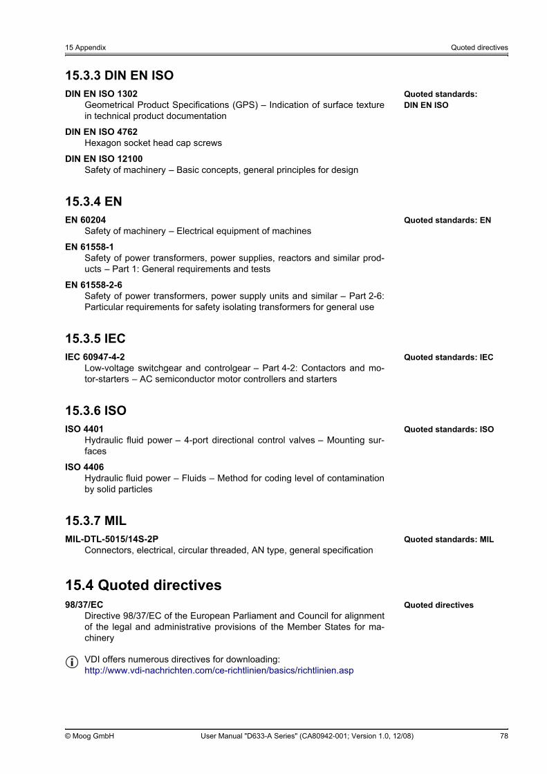
15 Appendix Quoted directives
© Moog GmbH User Manual "D633-A Series" (CA80942-001; Version 1.0, 12/08) 78
15.3.3 DIN EN ISOQuoted standards: DIN EN ISO
DIN EN ISO 1302Geometrical Product Specifications (GPS) – Indication of surface texturein technical product documentation
DIN EN ISO 4762Hexagon socket head cap screws
DIN EN ISO 12100Safety of machinery – Basic concepts, general principles for design
15.3.4 ENQuoted standards: ENEN 60204
Safety of machinery – Electrical equipment of machines
EN 61558-1Safety of power transformers, power supplies, reactors and similar prod-ucts – Part 1: General requirements and tests
EN 61558-2-6Safety of power transformers, power supply units and similar – Part 2-6:Particular requirements for safety isolating transformers for general use
15.3.5 IECQuoted standards: IECIEC 60947-4-2
Low-voltage switchgear and controlgear – Part 4-2: Contactors and mo-tor-starters – AC semiconductor motor controllers and starters
15.3.6 ISOQuoted standards: ISOISO 4401
Hydraulic fluid power – 4-port directional control valves – Mounting sur-faces
ISO 4406Hydraulic fluid power – Fluids – Method for coding level of contaminationby solid particles
15.3.7 MILQuoted standards: MIL MIL-DTL-5015/14S-2P
Connectors, electrical, circular threaded, AN type, general specification
15.4 Quoted directivesQuoted directives 98/37/EC
Directive 98/37/EC of the European Parliament and Council for alignmentof the legal and administrative provisions of the Member States for ma-chinery
VDI offers numerous directives for downloading:http://www.vdi-nachrichten.com/ce-richtlinien/basics/richtlinien.asp


TAKE A CLOSER LOOK.Moog solutions are only a click away. Visit our worldwide Web site for more information and the Moog facility nearest you.
Argentina+54 11 4326 [email protected]
Australia+61 3 9561 [email protected]
Austria+43 664 144 65 [email protected]
Brazil+55 11 3572 [email protected]
China+86 21 2893 [email protected]
Finland+358 9 2517 [email protected]
France+33 1 4560 [email protected]
Germany+49 7031 622 [email protected]
Hong Kong+852 2 635 [email protected]
India+91 80 4120 [email protected]
Ireland+353 21 451 [email protected]
Italy+39 0332 421 [email protected]
Japan+81 463 55 [email protected]
Luxembourg+352 40 46 [email protected]
Netherlands+31 252 462 [email protected]
Norway+47 64 94 19 [email protected]
Russia+7 83171 [email protected]
Singapore+65 6773 [email protected]
South Africa+27 12 653 [email protected]
South Korea+82 31 764 [email protected]
Spain+34 902 133 [email protected]
Sweden+46 31 680 [email protected]
Switzerland+41 71 394 [email protected]
United Kingdom+44 1684 [email protected]
USA+1 716 652 [email protected]
www.moog.com/industrial© 2008 Moog GmbHAll rights reserved.
User Manual "D633-A Series"(CA80942-001; Version 1.0, 12/08)