D5.4 Reasoning mechanisms · THALES – Thales Services SAS, ... RE Restricted to a group specified...
91
Reasoning mechanisms to support the identification and the analysis of problems associated with user requests Project acronym: COMPAS Project name: Compliance-driven Models, Languages, and Architectures for Services Call and Contract: FP7-ICT-2007-1 Grant agreement no.: 215175 Project Duration: 01.02.2008 – 28.02.2011 (36 months) Co-ordinator: TUV Technische Universitaet Wien (AT) Partners: CWI Stichting Centrum voor Wiskunde en Informatica (NL) UCBL Université Claude Bernard Lyon 1 (FR) USTUTT Universitaet Stuttgart (DE) TILBURG UNIVERSITY Stichting Katholieke Universiteit Brabant (NL) UNITN Universita degli Studi di Trento (IT) TARC-PL Telcordia Poland (PL) THALES Thales Services SAS (FR) PWC Pricewaterhousecoopers Accountants N.V. (NL) This project is supported by funding from the Information Society Technologies Programme under the 7th Re- search Framework Programme of the European Union. D5.4 Version: 2.1 Date: 2009-12-22 Dissemination status: PU Document reference: D5.4
Transcript of D5.4 Reasoning mechanisms · THALES – Thales Services SAS, ... RE Restricted to a group specified...

Reasoning mechanisms to support the identification and the analysis of problems associated with user requests
Project acronym: COMPAS
Project name: Compliance-driven Models, Languages, and Architectures for Services
Call and Contract: FP7-ICT-2007-1
Grant agreement no.: 215175
Project Duration: 01.02.2008 – 28.02.2011 (36 months)
Co-ordinator: TUV Technische Universitaet Wien (AT)
Partners: CWI Stichting Centrum voor Wiskunde en Informatica (NL)
UCBL Université Claude Bernard Lyon 1 (FR)
USTUTT Universitaet Stuttgart (DE)
TILBURG UNIVERSITY Stichting Katholieke Universiteit Brabant (NL)
UNITN Universita degli Studi di Trento (IT)
TARC-PL Telcordia Poland (PL)
THALES Thales Services SAS (FR)
PWC Pricewaterhousecoopers Accountants N.V. (NL)
This project is supported by funding from the Information Society Technologies Programme under the 7th Re-
search Framework Programme of the European Union.
D5.4
Version: 2.1 Date: 2009-12-22
Dissemination status: PU Document reference: D5.4
FP7-215175 COMPAS D5.4v2.1
File: D5.4_Reasoning mechanisms.doc Page 2 of 91
Project no. 215175
COMPAS
Compliance-driven Models, Languages, and Architectures for Services
Specific Targeted Research Project
Information Society Technologies
Start date of project: 2008-02-01 Duration: 36 months
D5.4 Reasoning mechanisms to support the identification and the analysis of problems associated with user requests
Revision 2.1
Due date of deliverable: 2009-12-31
Actual submission date: 2009-12-22
Organisation name of lead partner for this deliverable:
UNITN – University of Trento, Italy
Contributing partner(s):
TILBURG – University of Tilburg, Netherlands
UCBL – Université Claude Bernard Lyon 1, France
USTUTT – Universitaet Stuttgart, Germany
TARC-PL – Telcordia Poland, Poland
THALES – Thales Services SAS, France
Project funded by the European Commission within the Seventh Framework Programme Dissemination Level
PU Public X PP Restricted to other programme participants (including the Commission Services) RE Restricted to a group specified by the consortium (including the Commission Services) CO Confidential, only for members of the consortium (including the Commission Services)

FP7-215175 COMPAS D5.4v2.1
File: D5.4_Reasoning mechanisms.doc Page 3 of 91
History chart Issue Date Changed page(s) Cause of change Implemented by 0.1 2009-07-22 All sections New document UNITN 0.2 2009-07-31 All sections Agreement with contributing
partners on contributions and structure of deliverable
UNITN
0.3 2009-10-09 Section 8 Add new text UNITN 0.4 2009-10-12 Section 7 Add new text UNITN 0.5 2009-10-13 Section 7 Updates UNITN 0.6 2009-10-27 Section 3, 7,8 and 9 Add new text and updates UNITN, TARC-
PL 0.7 2009-11-11 Section 6 Add text Tilburg 0.8 2009-11-15 Section 3 Add text and updates Tilburg 0.9 2009-11-17 Section 8 and 6 Delete Section 8 and update
Table 3 UNITN
1.0 2009-11-20 Section 2 List of Figures
Updates Tilburg
1.1 2009-11-22 Section 2 Adding the SSE pattern Tilburg 1.2 2009-11-24 All sections Update labels and format UNITN 1.3 2009-11-25 Section 7 Updates UNITN 1.4 2009-11-27 Section 2 Updates Tilburg 1.5 2009-11-28 Section 6.4 New text UNITN 1.6 2009-12-02 Section 1, 3, 3.3, 9 Add new text and updates USTUTT 1.7 2009-12-07 Section 6, Table 1,
and References Updates according to UNITN internal review
UNITN
1.8 2009-12-10 Table 1 Updates according to PWC comments
UNITN
1.9 2009-12-17 All sections Update to include contributions from done by TIL after the re-view and also format the text.
UNITN
1.95 2009-12-18 First paragraph of Section 3 and Section 3.3
Revision due to internal review of USTUTT contribution
USTUTT
1.96 2009-12-21 All sections Revision due to internal review of USTUTT contribution
UNITN
1.97 2009-12-21 Section 2 Updates based on USTUTT comments
Tilburg
1.98 2009-12-22 Sections 1.2, 3.2, 4 Updates based on internal re-view comments and comments inside the text
TARC-PL
2.0 2009-12-22 Final formatting Alignment of formats needed UNITN
2.1 2009-12-23 Approve & Release TUV

FP7-215175 COMPAS D5.4v2.1
File: D5.4_Reasoning mechanisms.doc Page 4 of 91
Authorisation No. Action Company/Name Date 1 Prepared UNITN 2009-12-22 2 Approved TUV 2009-12-23 3 Released TUV 2009-12-23
Disclaimer: The information in this document is subject to change without notice. Company or product names mentioned in this document may be trademarks or registered trademarks of their respective companies.
All rights reserved. The document is proprietary of the COMPAS consortium members. No copying or distribut-ing, in any form or by any means, is allowed without the prior written agreement of the owner of the property rights.
This document reflects only the authors’ view. The European Community is not liable for any use that may be made of the information contained herein.

FP7-215175 COMPAS D5.4v2.1
File: D5.4_Reasoning mechanisms.doc Page 5 of 91
Contents 1. Introduction ................................................................................................................................. 9
1.1. Purpose and scope.............................................................................................................. 10
1.2. Reference scenario: WatchMe .......................................................................................... 12
1.3. Document overview ........................................................................................................... 13
1.4. Definitions and glossary .................................................................................................... 13
1.5. Abbreviations and acronyms............................................................................................. 14
2. Design-time violations and root cause analysis ...................................................................... 15
2.1. CRL meta-model extensions ............................................................................................. 16
2.2. Root cause analysis for design-time compliance violations ........................................... 19
2.2.1. CRT of Exists, Precedes, LeadsTo and PleadTo patterns ...................................... 20
2.2.2. CRT trees of Absence, Universality and BoundedExistence patterns................... 21
2.2.3. CRT trees of ChainPrecedence and ChainLeadsTo Patterns ................................. 22
2.2.4. CRT trees of composite patterns .............................................................................. 23
2.2.5. CRTs of the satisfaction of atomic patterns ............................................................ 24
2.2.6. CRTs of newly introduced compliance patterns ..................................................... 26
2.2.7. Current Reality Trees in action ................................................................................ 29
2.3. Consistency Checking of Compliance Rules ................................................................... 36
3. CEP rules, process fragments, and events ............................................................................... 38
3.1. COMPAS event model ...................................................................................................... 38
3.2. Complex Event Processing (CEP) rules ........................................................................... 41
3.3. Using Process fragments for augmenting processes with compliance control logic..... 42
3.3.1. Example of business process logic fragment .......................................................... 43
3.3.2. Example of annotation business process fragment and textual annotation ........... 44
3.3.3. Information required for checking of compliance concerns of WatchMe use case scenario ...................................................................................................................... 45
3.4. COMPAS event model ...................................................................................................... 54
4. Run-time rules evaluation......................................................................................................... 55
5. Business protocol monitoring .................................................................................................. 56
5.1. Protocol monitoring component (the overall architecture) ............................................. 57
5.2. Transformation of BPEL business processes to business protocol ................................ 60
5.2.1. Transformation of basic activities............................................................................ 60
5.2.2. Transformation of structured activities ................................................................... 61
5.3. Monitoring language ......................................................................................................... 61
5.4. Monitoring language properties ........................................................................................ 63

FP7-215175 COMPAS D5.4v2.1
File: D5.4_Reasoning mechanisms.doc Page 6 of 91
6. Assessing and reporting on compliance .................................................................................. 63
6.1. Key Compliance Indicators (KCIs) .................................................................................. 63
6.2. Specifying KCIs ................................................................................................................. 65
6.3. KCIs in the WatchMe scenario ......................................................................................... 66
6.4. Computing KCIs ................................................................................................................ 67
7. Root cause analysis of runtime compliance violations ........................................................... 68
7.1. Classification and decision trees ....................................................................................... 69
7.2. Implementation .................................................................................................................. 70
8. Meta-model and DSL for compliance to security policies ..................................................... 73
8.1. SOA security ...................................................................................................................... 73
8.2. Model-driven architecture applied to security ................................................................. 75
8.2.1. MDA based approaches for compliance to security policies ................................. 76
8.3. Meta-model and DSL for security .................................................................................... 77
8.3.1. Access control DSL .................................................................................................. 78
8.3.2. ACD Editor ............................................................................................................... 83
8.3.3. Access control specification ..................................................................................... 84
9. Reference documents ................................................................................................................ 87
9.1. Internal documents ............................................................................................................ 87
9.2. External documents ........................................................................................................... 88
List of figures Figure 1 Current version of the overall COMPAS architecture [D7.1]................................. 11
Figure 2 Design-time reasoning approach ............................................................................... 16
Figure 3 Extended CRL meta-model [D2.3] ........................................................................... 17
Figure 4 Newly proposed compliance patterns ....................................................................... 18
Figure 5 Newly proposed compliance patterns ....................................................................... 18
Figure 6 Compliance constraints taxonomy ............................................................................ 20
Figure 7 CRL of Exists, Precedes, LeadsTo and PLeadsTo patterns .................................... 21
Figure 8 CRT Tree of Absence, Universality, and BoundedExistence patterns ................... 22
Figure 9 CRT of ChainPrecedence and ChainLeadsTo patterns ........................................... 23
Figure 10 CRT of ChainPrecedence and ChainLeadsTo patterns ........................................... 24
Figure 11 CRT of ChainPrecedence and ChainLeadsTo patterns ........................................... 24
Figure 12 CRT of the satisfaction of Precedes, Exists and LeadsTo atomic patterns ............ 25
Figure 13 CRT of the satisfaction of Absence, Universal and BoundedExistence atomic patterns .......................................................................... 25

FP7-215175 COMPAS D5.4v2.1
File: D5.4_Reasoning mechanisms.doc Page 7 of 91
Figure 14 CRT of the satisfaction of Chain precedence and Chain LeadsTo atomic patterns ........................................................................................................... 26
Figure 15 CRT of Exclusive and MutexChoice compliance patterns ..................................... 27
Figure 16 CRT of Inclusive, Prerequisite, Substitutes and Corequiste compliance patterns . 28
Figure 17 CRT of SegregatedFrom and SSE compliance patterns .......................................... 28
Figure 18 CRT of (T precedes R) Imply ((S exists) And (P Inclusive Q)) composite pattern....................................................................................................... 29
Figure 19 CRT of (T LeadsTo S) Xor (P Isabsent)................................................................... 30
Figure 20 CRT for the violation to R1 ....................................................................................... 32
Figure 21 CRT for the violationsviolation to R2 and R3R1 .................................................... 33
Figure 22 CRT for the violations to R2 and R3 ........................................................................ 35
Figure 23 User Interface design of root cause analysis output ................................................ 35
Figure 24 Conceptual model of the compliance management problem. The figure introduces the basic concepts, terminology and relationships. ............ 43
Figure 25 BPLF realizing compliance requirement composition permission ......................... 44
Figure 26 ABPF and textual annotation for realizing compliance requirement that access to WatchMe service is protected ........................................................... 45
Figure 27 Complex event processing ........................................................................................ 55
Figure 28 WatchMe Business protocol...................................................................................... 57
Figure 29 Monitoring strategy.................................................................................................... 58
Figure 30 Business protocol monitor architecture .................................................................... 58
Figure 31 Relationship among process, goals and indicators (adapted from [Cob05]).......... 64
Figure 32 How to abstract KCIs: visual alert levels ................................................................. 64
Figure 33 COMPAS run-time architecture................................................................................ 65
Figure 34 Example of a Decision Tree ...................................................................................... 70
Figure 35 Details of the Data Preparation ................................................................................. 71
Figure 36 An example of decision tree produced by Weka ..................................................... 72
Figure 37 Meta-model Transformation ..................................................................................... 76
Figure 38 XACML policy model [Oas03] ................................................................................ 79
Figure 39 Access control DSL model ........................................................................................ 80
Figure 40 Access control DSL model (Subject) ....................................................................... 81
Figure 41 Access control DSL model (Rule) ............................................................................ 81
Figure 42 AAccess control system............................................................................................. 82
Figure 43 ACD editor ................................................................................................................. 83
Figure 44 Role hierarchy definition ........................................................................................... 83
Figure 45 AccessAccess permission rule .................................................................................. 84
FP7-215175 COMPAS D5.4v2.1
File: D5.4_Reasoning mechanisms.doc Page 8 of 91
Figure 46 AAccess deny rule ..................................................................................................... 84
Figure 47 Sign form authorization ............................................................................................. 85
Figure 48 Dynamic separation of duties .................................................................................... 86
List of tables Table 1 Compliance requirements of the WatchMe scenario ............................................... 13
Table 2 Compliance patterns mapping ................................................................................... 19
Table 3 Example compliance requirements relevant to the Internet reseller Scenario [D6.1] .......................................................................................................... 31
Table 4 Required information for monitoring and mining of WatchMe scenario............... 53
Table 5 WatchMe KCIs........................................................................................................... 67
Table 6 Excerpt of the data training set with tuples and class label attributes .................... 72
List of listings Listing 1 COMPAS Event model XSD schema....................................................................... 39
Listing 2 WatchMeGetVideoStream event instantiation ......................................................... 40
Listing 3 WatchMeGetAudioStream event instantiation ........................................................ 40
Listing 4 A Sample Event with Identifiers ............................................................................... 55
Listing 5 State log (xml serialisation)) ..................................................................................... 61
Listing 6 BPath external variables definition ........................................................................... 62
Listing 7 BPath requirements definition................................................................................... 62
Listing 8 Case statement to compute the %OfCompliance indicator ..................................... 68
Listing 9 SQL statements to compute %OfCompliance indicator .......................................... 68
Listing 10 XACML Policy Fragment for separation of duty.................................................... 87

FP7-215175 COMPAS D5.4v2.1
File: D5.4_Reasoning mechanisms.doc Page 9 of 91
Abstract This deliverable defines the reasoning mechanisms and algorithms that are used in COMPAS to analyze and report on deviations of the process definitions from the desired compliance concern targets, such as regulations, QoS agreements, security requirements and licenses. The deliverable introduces two approaches to identify the root causes of possible violations, one that operates at design time (before the execution of processes) and one that operates at as-sessment time (after the execution of processes). As a means for reporting on compliance, the deliverable discusses the computation of so-called Key Compliance Indicators (KCIs), pro-viding at a glance insight into the compliance state of a company. The deliverable further in-cludes a meta-model and DSL for compliance to security policies.
1. Introduction This deliverable represents the aggregation point for all compliance governance efforts in WP5, connecting almost all the concepts, models, algorithms and software modules devel-oped in its context and in the work packages directly related to it. Although the deliverable is entitled “Reasoning mechanisms to support the identification and the analysis of problems associated with user requests”, the title “Reasoning mechanisms for the evaluation, analysis and reporting on compliance” would describe better its actual contribution to the project, as already hinted at by the short description of the deliverable in the Description of Work [DoW]. The deliverable does actually introduce an extension to both the Compliance Request Language [D2.2] and to its pattern-based backbone, in order to identify design-time root causes for problems associated with user requests, yet such are not the only focus of the de-liverable, as its title might suggest.
The deliverable addresses the following research questions regarding compliance governance:
− How can we concretely model compliance rules and business process fragments lev-eraging on the COMPAS infrastructure?
− How can we evaluate compliance with rules and fragments in parallel to the execution of business processes?
− How can we effectively assess compliance in an aggregated form and report on it?
− How can we identify the root causes of detected violations or deviations from ex-pected behaviours?
− How do we specify security concerns by means of a dedicated DSL?
As we will see, the initial research questions are strictly related to prior deliverables, such as [D2.2], [D2.3], [D4.3], [D4.4] and [D5.3], and are discussed in this deliverable in order to clarify the latest findings and agreements and to ease the reading of the deliverable. The ques-tions about how to assess compliance and how to identify root causes are, instead, also related to deliverables that are still to come, mainly [D2.6] and [D5.5], which will provide the proto-type implementation of the tools that will allow the users of COMPAS to navigate through the results computed by the compliance assessment algorithms and to perform drill-down and roll-up operations, so as to inspect different levels of details for detected violations.
Finally, for the specification of security requirements the deliverable introduces the graphical security DSL, which can be used by the COMPAS experts to visually specify security com-pliance requirements and to transform them into the necessary instrumentation to check busi-ness processes for violations.

FP7-215175 COMPAS D5.4v2.1
File: D5.4_Reasoning mechanisms.doc Page 10 of 91
1.1. Purpose and scope The purpose of this deliverable is to describe the solutions that have been conceived to ad-dress the research questions mentioned in the previous section and to contextualize them in-side the overall compliance governance approach of COMPAS.
The scope of the deliverable is graphically represented in Figure 1, which shows the overall architecture of COMPAS. The highlighted boxes identify which architectural components are affected by the algorithms presented in this deliverable. Specifically, in this deliverable we briefly discuss the latest version of the common event format adopted for the transmission of events over the shared Enterprise Service Bus. Events are the input for the Runtime Compli-ance Monitoring and the Business Protocol Monitoring modules, which focus on the evalua-tion of compliance rules and business protocols/process fragments, respectively. The compu-tation of KCIs and the root causes analysis approach based on the assessment of event logs are the core of the Analysis/Business Intelligence module that provides the necessary input for the Compliance Governance Dashboard [D5.5]. The algorithms and techniques for the de-sign-time root cause analysis are developed in the context of WP5, yet their outputs will be visualized by the Compliance Language Request Tools to be developed in WP2.
The development of the security DSL is a contribution to the DSL specification and comes with an own DSL Editor targeted toward the average security expert.

FP7-215175 COMPAS D5.4v2.1
File: D5.4_Reasoning mechanisms.doc Page 11 of 91
Figure 1 Current version of the overall COMPAS architecture [D7.1]

FP7-215175 COMPAS D5.4v2.1
File: D5.4_Reasoning mechanisms.doc Page 12 of 91
1.2. Reference scenario: WatchMe In order to better contextualize the discussions and examples throughout the deliverable, we will refer to the case study provided by TARC-PL, i.e., the so-called WatchMe [D6.1][D5.3]. We briefly summarize the scenario in the following, highlighting the specific compliance re-quirements addressed in this deliverable:
The WatchMe scenario focuses on advanced telecom services offered by a mobile virtual network operator (MVNO). In the specified greenfield scenario (meaning that we develop everything – processes, rules, fragments, etc. – from scratch), there are basically three chal-lenges posed to the monitoring of the compliance status:
1. The scenario deals with internal policy, which states that the protection of WatchMe company
2. The scenario deals with different licenses adopted by the different audio and video providers of the MVNO (i.e., pay-per-view or time-based subscriptions).
3. The scenario deals with Quality of Service (QoS) concerns. Customers paying WatchMe for the delivery of video and audio streams also pay for agreed on service levels. In order to assess whether WatchMe is really able to fulfil its promises, it is necessary to monitor and control the agreed on QoS parameters.
Table 1 summarizes the list of compliance requirements used in the WatchMe scenario re-garding both the licensing and the QoS issues and informally introduces the controls settled to check.
Compliance Requirements
Description of Com-pliance Require-ments
Control
Inte
rnal
po
licy
Access to WatchMe service is protected.
The usage of WatchMe service is only allowed for registered users.
A user has to identify himself when inter-acting with the WatchMe service.
Lice
nsin
g
Pay-per-view plan When the WatchMe company subscribes for the Pay-per-view plan it acquires a limited number of streams based on the amount paid to the media sup-plier.
When WatchMe company subscribes for the Pay-per-view plan it has to pay 29.90 euro first and then receive 300 streams from the media supplier.
Time-based plan When the WatchMe company subscribes for the Time-based plan it acquires any number of times any possible streams in a certain period, based on the amount paid to the media supplier.
When WatchMe company subscribes for the time-based plan it has to pay 89.90 euro first and then receive an unlimited number of times any available stream from the media supplier in a 30 days period starting from the contract start date.
Composition per-mission
Only pre-defined combinations of video
VideoTube can only have audios streams from AudioTube or QuickAudio.

FP7-215175 COMPAS D5.4v2.1
File: D5.4_Reasoning mechanisms.doc Page 13 of 91
and audio providers are allowed due to the li-censes specified by the video provider.
QuickVideo can only have audio streams from QuickAudio.
QoS
Delivery Rate The WatchMe service must deliver in a fixed period of time the specified number of URLs for downloading a stream.
The WatchMe service must deliver a valid URL at least in 90% of requests per cus-tomer subscription.
Availability The WatchMe service must be available as specified to the cus-tomer in the contrac-tual agreement of the subscription.
The WatchMe service must be available 99% of the time per customer subscrip-tion.
Response time The response time for getting a URL of the requested media is as specified to the cus-tomer in the contrac-tual agreement of the subscription.
The WatchMe service provides a URL of the requested media within 45 seconds to the customer.
Table 1 Compliance requirements of the WatchMe scenario
1.3. Document overview The document is structured into three, independent parts: (1) design-time root cause analysis, (2) analysis of and reporting on compliance, (3) DSL and meta-model for compliance with security policies.
Part 1 consists in Section 3, which specifically focuses on design-time compliance violations and the identification of their root causes via current reality trees. Part 2 comprises several sections: Section 3 introduces the event-based context that characterizes the COMPAS as-sessment solutions and describes how compliance rules and process annotation fragments are represented and bound to events. Section 4 shows the complex event processing approach to the assessment of compliance rules. Section 5 describes the business protocol monitoring ap-proach for complex compliance requirements. Next, Section 6 and Section 7 focus on compli-ance assessment by means of KCIs and by means of root cause analysis starting from real violations in the Event log. Finally, Part 3 of the deliverable consists of Section 8, which de-scribes a meta-model and DSL for expressing security compliance requirements.
1.4. Definitions and glossary The most important terminology concerning the COMPAS project is listed on the public COMPAS Web-Site [D7.1] available at http://www.compas-ict.eu, section Terminology. This helps to make the overall COMPAS approach more comprehensive for the general public.

FP7-215175 COMPAS D5.4v2.1
File: D5.4_Reasoning mechanisms.doc Page 14 of 91
1.5. Abbreviations and acronyms ABPF Annotation Business Process Fragment
AC Action constraint
ACD Access Control DSL
ARF Attribute-relation File
BI Business Intelligence
BP Business Process
BPEL Business Process Execution Language
BPLF Business Process Logic Fragment
BPMN Business Process Modeling Notation
CBE Common Base Event
CEP Complex Event Processing
CMMI Capability Maturity Model Integration
CRL
CRLT
CRT
Compliance Request Language
Compliance Request Language Tool
Current Reality Tree
DMCA Digital Millennium Copyright Act
DSL
DW
ECA
Domain Specific Language
Data Warehouse
Event-Condition-Action
ESB Enterprise Service Bus
ETL Extraction, Transformation, and Load
EPL Event Processing Language
IT Information Technology
KCI Key Compliance Indicator
KPI
LTL
Key Performance Indicator
Linear Temporal Logic
MDA Model Driven Architecture
MVNO Mobile Virtual Network Operator
OLAP On-line Analytical Processing
PIM Platform Independent Model
PMBOK Project Management Body of Knowledge
PSM Platform Specific Model

FP7-215175 COMPAS D5.4v2.1
File: D5.4_Reasoning mechanisms.doc Page 15 of 91
QoS
RBCA
RC
RCA
Quality of Service
Role Based Access Control
Rule constraint
Root Cause analysis
SQL Structured Query Language
SAML Security Assertion Markup Language
SOA Service Oriented Architecture
SSE Second-Set-of-Eyes
SSL Secure Sockets Layer
TLS Transport Layer Security
TOC Theory of Constraint
UDE Undesirable effect
UMLUML Unified Modeling Language
XACML eXtensible Access Control Markup Language
XKMS XML Key Management Specification
Weka Waikato Environment for Knowledge Analysis
2. Design-time violations and root cause analysis Root Cause analysis (RCA) is a class of analysis techniques that aim to trace a problem to its origin to identify the root causes of the problem under consideration. Identifying and address-ing the root causes is the key to solve the main problem. The goal of this Section is to present techniques to identify root causes of compliance violations during design-time and provide remedies as guidelines/suggestions that help the expert to resolve the compliance deviations.
There are various root cause analysis techniques, e.g.: Barrier analysis, Casual factor tree analysis, change analysis and current reality tree, etc. For the purpose of this Section, we have selected the Current Reality Tree (CRT) of Goldratt’s Theory of Constraints (TOC) [Det97] as the adapted root cause analysis technique. A current reality tree is a statement of an under-lying core problem and the symptoms that arise from it. It maps out a sequence of cause and effect from the core problem to the symptoms. Most of the symptoms will arise from one core problem or a core conflict. If the core problem is removed, each of the symptoms as well might be removed. Operationally the process works backwards from the apparent undesirable effects or symptoms to uncover or discover the underlying core causes [Det97] and [Mos06]. The CRT was chosen due to its simplicity, the visual representation of the causes and effects, and its suitability with the compliance problem.
The pattern-based system which represents the backbone of the Compliance Request Lan-guage (CRL) introduced in Deliverable 2.2deliverable [D2.2] and extended in Deliverable 2.3deliverable [D2.3], will serve as taxonomy to reason about design-time compliance viola-tions. The compliance pattern class was introduced in Deliverable 2.3deliverable [D2.3] to capture patterns relevant to the compliance problem. In this section, first we introduce some extensions to the pattern-based systems by introducing seven new compliance patterns. Next we build up the compliance constraints taxonomy, which is the core of the root cause analy-

FP7-215175 COMPAS D5.4v2.1
File: D5.4_Reasoning mechanisms.doc Page 16 of 91
sis. The necessary CRL meta-model extensions are presented in Section 2.1Figure 2 presents the proposed design time reasoning approach. The approach first starts from the ‘Compliance Request Language Tools’ (the prototype under development by Tilburg University), where the consistency checking between the set of applicable compliance rules takes place. As shown in the upper left part of Figure 2, the inputs to the consistency checking module are: (i) a set of compliance rules, formalized as LTL, and (ii) a set of rule constraints (details are dis-cussed in Section 3.3.1). The output of the consistency checking module is a consistent set of compliance rules. Next, the set of compliance rules along with the end-to-end business proc-ess model will be sent to the ‘Process verification tools’ of WP3. The output from the ‘Proc-ess verification tools’ is the “Compliance verification results”. If violations exist, the root cause analysis technique described in Section 2.2 will take place, and the user will be pro-vided with guidelines/suggestions as remedies to resolve the compliance deviations. The user can use these guidelines to modify the business process model. The counter-example tracing facility from “Process verification tools” (WP3) can also help the expert to focus on the parts in the business process model that are the source of violations. Once the end-to-end business process model is updated, it will be sent again to “Process verification tools” to check the compliance. This process iterates continuously until a compliant end-to-end business process model is produced.
Figure 2 Design-time reasoning approach
The contribution of this section is twofold: first, providing an algorithm to reason about the conflicts between compliance rules; the proposed consistency checking algorithm is discussed in Section 2.3. Second, the root cause analysis to reason about design-time compliance devia-tions, which is drawn in Section 2.2.
2.1. CRL meta-model extensions A meta-model for the CRL was introduced in Deliverable 2.2deliverable [D2.2]. The meta-model incorporates Dwyer’s property specification patterns introduced in [DAC98] and ex-tended in [YMH+06] to enable pattern composition, and based on temporal logic formulas. The CRL pattern-based system will be used as taxonomy for reasoning about the root causes of compliance violations during design-time. In this Section, we first propose some more ex-

FP7-215175 COMPAS D5.4v2.1
File: D5.4_Reasoning mechanisms.doc Page 17 of 91
tensions to the CRL meta-model than the latest version proposed in Deliverable 2.3deliverable [D2.3]. The notion of compliance patterns has been introduced in Deliverable 2.3deliverable [D2.3] to capture patterns relevant to the compliance problem. As an example, we proposed in Deliverable 2.3deliverable [D2.3] the ‘SegregatedFrom’ pattern which cap-tures the typical four eyeeyes principle compliance requirement. The extended CRL meta-model is shown in Figure 3.
In this Section a set of compliance patterns were identified inspired from [LSG09]. Although the work in [LSG09] is dealing with managing the ad-hoc adoptions of the running business process instances, which is a different problem than the problem under consideration, we found the adaptations of these patterns into design time verification promising, since during instance adaptations the running instances should respect a set of constraints emerging from different sources. For example, the running business process instance should satisfy a set of strategic constraints that define the tactical elements of the process, such as the constraint that mandates the approval of a director for invoices beyond a certain value. However, the study in [LSG09] considers Deontic logic as the formal foundation of their approach.
Figure 3 Extended CRL meta-model [D2.3]
FP7-215175 COMPAS D5.4v2.1
File: D5.4_Reasoning mechanisms.doc Page 18 of 91
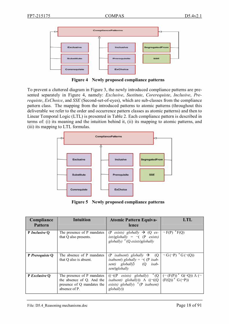
Figure 4 Newly proposed compliance patterns
To prevent a cluttered diagram in Figure 3, the newly introduced compliance patterns are pre-sented separately in Figure 4, namely: Exclusive, Sustitute, Corerequiste, Inclusive, Pre-requiste, ExChoice, and SSE (Second-set-of-eyes), which are sub-classes from the compliance pattern class. The mapping from the introduced patterns to atomic patterns (throughout this deliverable we refer to the order and occurrence pattern classes as atomic patterns) and then to Linear Temporal Logic (LTL) is presented in Table 2. Each compliance pattern is described in terms of: (i) its meaning and the intuition behind it, (ii) its mapping to atomic patterns, and (iii) its mapping to LTL formulas.
Figure 5 Newly proposed compliance patterns
Compliance Pattern
Intuition Atomic Pattern Equiva-lence
LTL
P Inclusive Q The presence of P mandates that Q also presents.
(P exists) globally (Q ex-ists)globally = ¬( (P exists) globally) ˅ (Q exists)globally
¬ F(P) ˅ F(Q)
P Prerequiste Q The absence of P mandates that Q also is absent.
(P isabsent) globally (Q isabsent) globally = ¬( (P isab-sent) globally) ˅ (Q isab-sent)globally
¬ G (¬P) ˅ G (¬(Q))
P Exclusive Q The presence of P mandates the absence of Q. And the presence of Q mandates the absence of P.
((¬((P exists) globally) ˅ (Q isabsent) globally)) Λ ((¬((Q exists) globally) ˅ (P isabsent) globally))
(¬ (F(P))˅ G(¬Q)) Λ (¬ (F(Q))˅ G (¬P))

FP7-215175 COMPAS D5.4v2.1
File: D5.4_Reasoning mechanisms.doc Page 19 of 91
Q Substitutes P Q substitute the absence of P
(P isabsent) globally (Q exists) globally = ¬((P isabsent) globally) ˅ (Q exists) globally
¬ G(¬(P)) ˅ F(Q)
P Corequiste Q Either activities P and Q should exist together or to be absent together
(P exists) globally iff (Q exists) globally = ((P exists) globally Λ (Q exists) globally)˅ ((P isab-sent) globally Λ (Q isabsent) globally)
(F(P) Λ F(Q)) ˅ (G(¬P) Λ G(¬Q) )
P MutexChoice Q
Either P or Q exists but not any of them or both of them
(P exists) globally Xor (Q ex-ists) globally = ((P exists) glob-ally Λ (Q isabsent) globally) ˅ (((Q exists) globally Λ (P isab-sent) globally)
(F(P) Λ G(¬(Q))) ˅ ( F(Q) Λ G(¬(P)) )
P SSE Q A certain activity should be performed (activity P) and reviewed (activity Q) by two different actors.
(P PLeadsTo Q) globally And (P.Actor1 Λ P.Actor2 ) And Actor1 ≠ Actor2
((¬Q W P) Λ (G(P F(Q)))) Λ G(P.Actor1 F (P.Actor2) Λ (Ac-tor1 ≠ Actor2))
Table 2 Compliance patterns mapping
2.2. Root cause analysis for design-time compliance violations The creation of a CRT usually starts with a list of problems called undesirable effects (UDEs), which represent negative or bad conditions. They are also “effects” because for most part they are caused by something else [MOS06]. The key question begins with “why a violation oc-curs?” (the root of the tree). The answer to this question will generate child(ren) of the UDE under consideration. For each child, which might be a UDE by itself, the same “why” ques-tion is asked, and the answer is depicted as a deeper level in the tree. This process continues iteratively until the UDE under consideration is the root cause of the problem (the leaves level of the tree).
The pattern-based system which represents the backbone of the CRL will be used as the tax-onomy for reasoning about the root causes of compliance violations. Figure 5 presents the compliance constraint taxonomy. Based on the CRL meta-model presented in Figure 5, four main classes of patterns were identified: (i) Order patterns, (ii) Occurrence patterns, (iii) Composite patterns, and (iv) Compliance patterns. In the proposed taxonomy we consider all pattern classes as sub-types from the compliance pattern class. This is mainly because all pat-tern classes are used to represent compliance requirements. We refer to the occurrence and order pattern classes initially introduced in [DAC98] as atomic patterns.
Basically, you can notice from the compliance patterns explanation in Table 2 that each newly introduced compliance pattern is a composite pattern, e.g. P MutexChoice Q is an ‘Xor’ com-position between the two atomic patterns: P exists and Q exists. The relationships to the exact Boolean operators that built up the proposed compliance patterns is omitted from Figure 5 to avoid a cluttered diagram, e.g. the inheritance relationship from MutexChoice pattern to the ‘Xor’ composite pattern is omitted. In next sub-sections, each pattern violation will be ana-lyzed for root causes using the CRT technique of Goldratt’s TOC [Det97], where each pattern violation is considered as an UDE. We grouped each set of related patterns in a single CRT.

FP7-215175 COMPAS D5.4v2.1
File: D5.4_Reasoning mechanisms.doc Page 20 of 91
Figure 6 Compliance constraints taxonomy
2.2.1. CRT of Exists, Precedes, LeadsTo and PleadTo patterns One of the main advantages of using the CRT technique to reason about root causes of com-pliance violations is that it is self-explanatory. Figure 6 represents the CRT of Exists, Pre-cedes, LeadsTo and PleadsTo patterns. The root of each CRT represents the UDE. For our purpose, an UDE is a violation to a specific pattern. Hence, each root of the tree represents a violation to one of the patterns from the pattern taxonomy presented in Figure 5. For example, as shown in Figure 6, the violation to (P Precedes Q) pattern is considered as a UDE of the precedes CRT. The construction of the deeper levels in the tree is guided by answering the ‘why’ question. Hence, the question that should be applied here is: why (P Precedes Q) is violated?. The answer to this question is: because ‘(Q Exists is satisfied) and (P exists is vio-lated) before it’, which is depicted as the second level of the tree. The same ‘why’ question is applied to the UDE under consideration and so on until the root causes of the problem are reached, which are the leaves of the tree. For each leave of the tree, the user will be provided with some guidelines as remedies to compliance violations. These guidelines are depicted in the CRTs as squared brackets linked to the leaves. For example, for the root cause ‘(P exists is violated)’, the guideline to solve the problem is: (i) add activity P to the model if P is atomic, or (ii) replace with corresponding CRT if P is composite.

FP7-215175 COMPAS D5.4v2.1
File: D5.4_Reasoning mechanisms.doc Page 21 of 91
Figure 7 CRL of Exists, Precedes, LeadsTo and PLeadsTo patterns
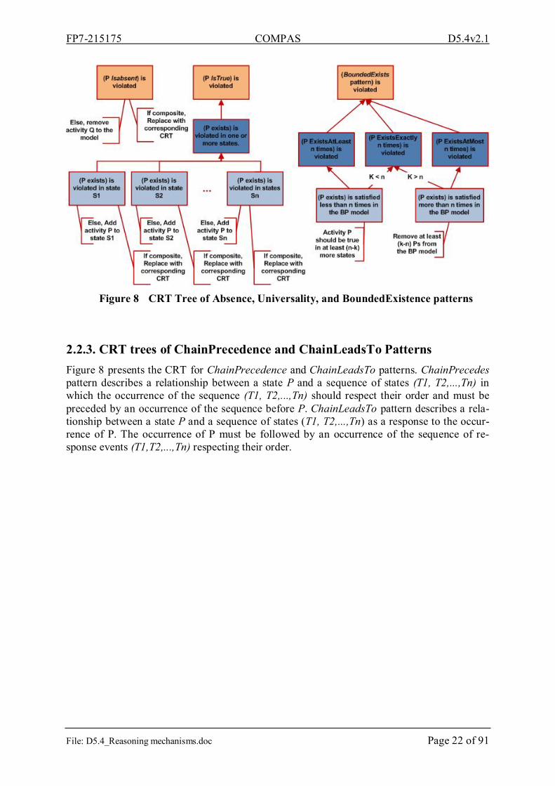
2.2.2. CRT trees of Absence, Universality and BoundedExistence patterns Figure 7 presents the CRT of Absence, Universality and BoundedExistence patterns. Bounded Existence indicates that ‘P must occur at least/exactly/at most k times in the model.’ Hence the “(BoundedExists pattern) is violated” UDE of Figure 7 has three children. The first node represents the violation to (P ExistsAtLeast n times), the second child represents the violation to (P ExistsExactly n times), and the third child represents the violation to (P ExistsAtMost n times). The variable ‘k’ represents the actual number of occurrence of ‘P’ in the business process model. Let’s consider the UDE “(P ExistsExactly n times) is violated”. This violation might be because either: (i) k is greater than n, or (ii) k is less than n. Appropriate guidelines will be provided to the user based on the actual root causes of the violation by traversing the corresponding CRT.
FP7-215175 COMPAS D5.4v2.1
File: D5.4_Reasoning mechanisms.doc Page 22 of 91
Figure 8 CRT Tree of Absence, Universality, and BoundedExistence patterns
2.2.3. CRT trees of ChainPrecedence and ChainLeadsTo Patterns Figure 8 presents the CRT for ChainPrecedence and ChainLeadsTo patterns. ChainPrecedes pattern describes a relationship between a state P and a sequence of states (T1, T2,...,Tn) in which the occurrence of the sequence (T1, T2,...,Tn) should respect their order and must be preceded by an occurrence of the sequence before P. ChainLeadsTo pattern describes a rela-tionship between a state P and a sequence of states (T1, T2,...,Tn) as a response to the occur-rence of P. The occurrence of P must be followed by an occurrence of the sequence of re-sponse events (T1,T2,...,Tn) respecting their order.

FP7-215175 COMPAS D5.4v2.1
File: D5.4_Reasoning mechanisms.doc Page 23 of 91
Figure 9 CRT of ChainPrecedence and ChainLeadsTo patterns
2.2.4. CRT trees of composite patterns The notion of ‘CompositePattern’ was introduced in [YMH+06] by using Boolean logic op-erators. Composite Patterns enable the definition of complex requirements by nesting other property patterns using the logical operators: And, Or, Xor, Not, Imply and Iff. The correctness of the pattern composition was also proved in [YMH+06]. Figure 9 presents the CRT of the composite patterns: And, Or, Xor, Not, Imply and Iff. For example, consider “(PropertyPat-tern1 and PropertyPattern2) is violated” UDE, let it be UDE1. According to the truth table of the ‘and’ operator, the ‘and’ statement is only true if its two operands are evaluated to true, otherwise the statement is evaluated to false. Applying the same ‘Why’ question to UDE1. The answer is either: (i) UDE1.1: (PropertyPattern1) is violated (ii) UDE1.2: (PropertyPat-tern2) is violated, or (iii) UDE1.3: (PropertyPattern1) is violated and (PropertyPattern2) is violated. UDE1.1, UDE1.2 and UDE1.3 correspond to one of the atomic patterns analyzed in the previous sub-sections, or one of the compliance patterns that will be discussed in Section 2.2.4. Hence, each UDE corresponds to an atomic or compliance pattern will be replaced with its corresponding CRT.
As shown in Figure 9, the violation to the ‘Or’ operator occurs when both of its operands are violated. The violation to the ‘Imply’ operator occurs when the first operand is satisfied and the second operand is violated. The violation to the ‘Xor’ operator occurs either when: (i) both operands are satisfied or (ii) both operands are violated. The violation to the ‘Iff’’ operand occurs either when: (i) first operand is violated and second operand is satisfied or (ii) first operand is satisfied and second operand is violated.

FP7-215175 COMPAS D5.4v2.1
File: D5.4_Reasoning mechanisms.doc Page 24 of 91
Figure 10 CRT of ChainPrecedence and ChainLeadsTo patterns
Notably, for the negation operator, “(Not PropertyPattern1) is violated”, the undesirable effect in this case is that “(PropertyPattern1) is satisfied”, which represents the opposite of the CRTs analyzed for the atomic patterns in the previous Sub-sections. For this purpose, each compli-ance pattern is re-analyzed where the undesirable effect (UDE) is that the property pattern is satisfied.
Figure 11 CRT of ChainPrecedence and ChainLeadsTo patterns
2.2.5. CRTs of the satisfaction of atomic patterns Figure 10, Figure 11, and Figure 12 present the CRTs of the satisfaction of all atomic property patterns analyzed above. For example, consider the CRT tree of the Precedes atomic pattern presented in Figure 10. The UDE of the tree is that ‘(P Precedes Q) is satisfied’ as opposed to

FP7-215175 COMPAS D5.4v2.1
File: D5.4_Reasoning mechanisms.doc Page 25 of 91
the CRT of the Precedes pattern, where the UDE is that the property is violated. The CRTs are built the same way as the CRTs discussed above by answering the ‘Why’ question to infer the causes behind the UDE under consideration. This process continues iteratively until the root causes of the primary UDE is reached which are depicted as the leaves of the tree.
Figure 12 CRT of the satisfaction of Precedes, Exists and LeadsTo atomic patterns
Figure 13 CRT of the satisfaction of Absence, Universal and BoundedExistence
atomic patterns

FP7-215175 COMPAS D5.4v2.1
File: D5.4_Reasoning mechanisms.doc Page 26 of 91
Figure 14 CRT of the satisfaction of Chain precedence and Chain LeadsTo atomic
patterns
2.2.6. CRTs of newly introduced compliance patterns As mentioned before, the CRTs of the newly introduced compliance patterns are instances from the CRTs of composite patterns discussed in Figure 9. The CRTs for the Exclusive and Mutexchoice compliance patterns are presented in Figure 13. As shown in the CRT of the MutexChoice composite pattern, it is an ‘Xor’ composition between the two atomic patterns (P exists) and (Q exists). Hence, the CRT for the ‘Xor’ composite pattern is instantiated result-ing in the CRT for the MutexChoice composite pattern shown in Figure 13. Usually, the in-stantiation process starts from the outermost pattern to the innermost pattern. The CRT of the Exclusive pattern is built up the same way based on the CRTs of ‘And’, ‘Imply’ composite patterns and isabsent atomic pattern.
Figure 14 presents the constructed CRTs for Inclusive, Prerequisite, Substitutes and Corequiste compliance patterns. As shown in Figure 14 the Inclusive CRT is built-up as an instantiation from CRTs for the Imply and exists patterns. The Prerequiste CRT is built-up as an instantiation from CRTs for the Imply and isabsent patterns. The Substitutes CRT is built-up as an instantiation from CRTs for the Imply and exists patterns, and the CRT of the satis-faction of isabsent pattern. The Corequiste CRT is built-up as an instantiation from CRTs for the Iff If and exists patterns, and the CRT of the satisfaction of exists pattern.
Figure 15 presents the CRTs for SegregatedFrom and SSE compliance patterns. The ‘Segre-gatedFrom’ pattern captures the typical four eye principle compliance requirement. It man-dates that two activities can’t be performed by the same role. As shown in the ‘P Segregated-From Q’ CRT in Figure 15, it first checks if activity P precedes activity Q, where the pro-ceeds CRT from Figure 6 is instantiated, then it checks if the two activities are performed by different roles. You can notice that the SegregatedFrom compliance pattern is a And compos-ite pattern.

FP7-215175 COMPAS D5.4v2.1
File: D5.4_Reasoning mechanisms.doc Page 27 of 91
Figure 15 CRT of Exclusive and MutexChoice compliance patterns
The SSE compliance requirement mandates that a certain activity is performed and reviewed by two different actors. As shown in the SSE CRT in Figure 15, it first checks if ‘P PLeadsTo Q’ is violated, where the ‘PLeadsTo’ CRT from Figure 21 is instantiated, and then it checks if the performance of the activity (P) and its review (Q) is performed by two different actors (Actor1 ≠ Actor2). You can notice that the exact actor that performs a specific task can only be checked during run-time. Hence during design-time, it can only be checked if P Pleads Q is violated.

FP7-215175 COMPAS D5.4v2.1
File: D5.4_Reasoning mechanisms.doc Page 28 of 91
Figure 16 CRT of Inclusive, Prerequisite, Substitutes and Corequiste compliance
patterns
Figure 17 CRT of SegregatedFrom and SSE compliance patterns

FP7-215175 COMPAS D5.4v2.1
File: D5.4_Reasoning mechanisms.doc Page 29 of 91
2.2.7. Current Reality Trees in action Figure 16 presents the CRT for the composite pattern: (T precedes R) Imply ((S exists) And (P Inclusive Q)). Here we assume that the scope for all patterns is globally, hence for simplifica-tion we removed scopes from the rule. We start with the outermost nested part, which is a composition between two patterns using the Imply logical operator. The first operand of the Imply operator is pattern1: (T Precedes P), and the second operand is Pattern2: ((S exists) And (P Inclusive Q)). Applying the CRT corresponding to the Imply composite pattern will result in adding the second and third level in the tree which are “(T precedes R) is satisfied and ((S exists) And (P Inclusive Q)) is violated” and “((S exists) And (P Inclusive Q)) is vio-lated” respectively. The UDE under consideration now is “((S exists) And (P Inclusive Q)) is by itself another And composite pattern. Applying the CRT for the And composite pattern will result in adding the rest of the levels to the tree. Hence based on the constructed CRT for the composite pattern (T precedes R) Imply ((S exists) And (P Inclusive Q)), the remedies to the violation of this composite pattern are: (i) Add activity S to the model and (ii) P can’t occur without Q. Add Q to the BP model. Note that the composite pattern under consideration is a two-level nested pattern.
Figure 18 CRT of (T precedes R) Imply ((S exists) And (P Inclusive Q)) composite
pattern
The Composite pattern under consideration in Figure 17 is: (T LeadsTo S) Xor (P Isabsent). By applying the CRT of the composite Xor pattern, will result in the CRT depicted below. In

FP7-215175 COMPAS D5.4v2.1
File: D5.4_Reasoning mechanisms.doc Page 30 of 91
Figure 17, the UDE “P IsAbsent is satisfied” is replaced by the CRT of the satisfaction of the IsAbsent pattern discussed in Figure 11.
Furthermore, Table 3 lists some examples of the relevant compliance requirements of the WatchMe scenario [6.1]. This scenario is only considered here for illustrative purposes. Each compliance constraint is described in terms of: (i) an identification of the compliance con-straint, (ii) compliance constraint description (iii) its representation using the compliance con-straint taxonomy discussed in Section 2.1, and (iv) an explanation of its pattern representa-tion.
Figure 19 CRT of (T LeadsTo S) Xor (P Isabsent)

FP7-215175 COMPAS D5.4v2.1
File: D5.4_Reasoning mechanisms.doc Page 31 of 91
ID Control Pattern representa-tion
Explanation
R1 Computer-generated sales order confirmations or can-celations are sent to cus-tomers after validating the order.
ValidateOrder(x,y) LeadsTo (SendCon-firm(x) MutexChoice SendCancel(x))
validateOrder for sales order y and customer x usually followed by either sending a con-firmation or cancela-tion to customer x.
R2 Sales orders over a set threshold require approval by management before acceptance by the system.
(SalesOr-der(y,threshold) ex-ists) Imply (Ap-prove(y, manager) Precedes Accept(y))
If there is a salesOrder y that exceeds a thresh-old threshold then Ap-prove action performed by managerI should usually precedes Ac-cept of order y.
R4 Appropriate segregation of duties should be main-tained. Specifically whether the credit checking is segregated from cash functions.
CreditChecking(x) SegregatedFrom Cashing(x)
CreditChecking func-tion for customer x should usually be seg-regated from the Cash-ing function for the same customer
Table 3 Example compliance requirements relevant to the Internet reseller Sce-nario [D6.1]
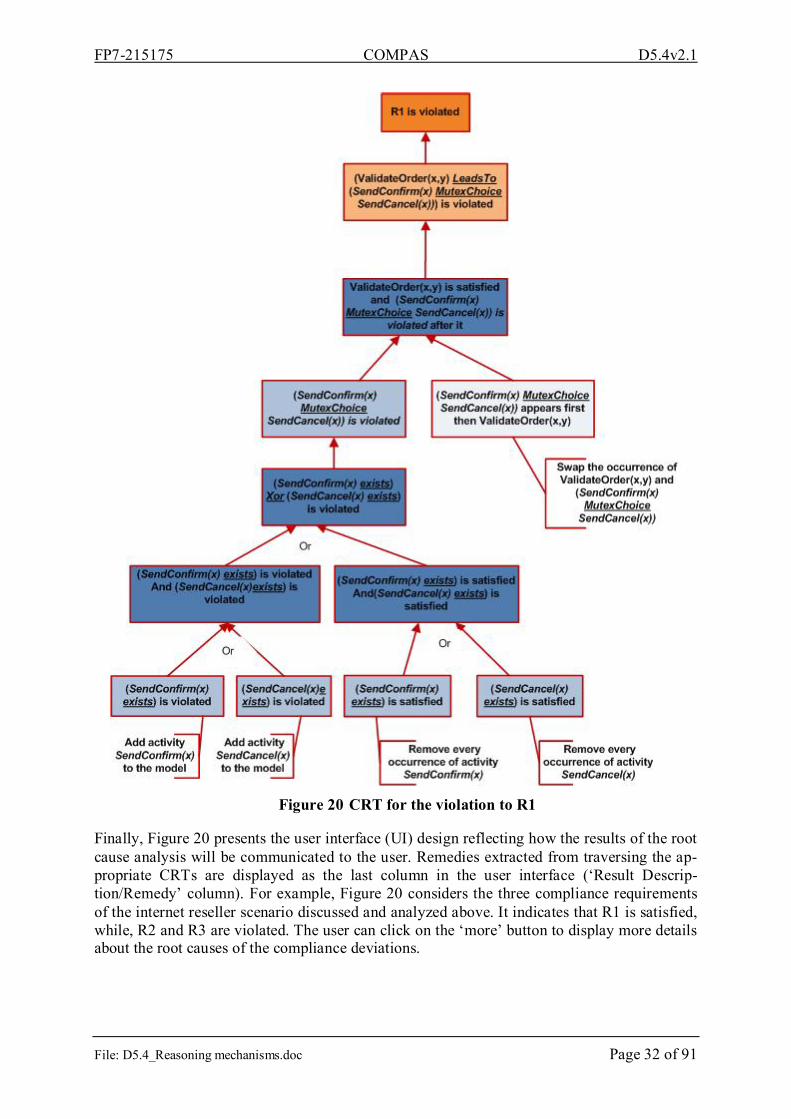
Assume that the ‘Process verification tools’ from WP3 (refer to Figure 2) detects violations to the three compliance requirements R1, R2 and R3. The CRT for the violation to R1 is auto-matically constructed as shown Figure 18 based on the proposed root cause analysis approach by instantiating LeadsTo and MutexChoice CRT discussed above. The CRTs of the violations to R2 and R3 are presented in Figure 23. The CRT of R2 is an ‘Imply’ composition between the two atomic patterns exists and precedes. The CRT for the violation to the typical four-eye-principle compliance requirements is shown in the right-hand side of Figure 23.
FP7-215175 COMPAS D5.4v2.1
File: D5.4_Reasoning mechanisms.doc Page 32 of 91
Figure 20 CRT for the violation to R1
Finally, Figure 20 presents the user interface (UI) design reflecting how the results of the root cause analysis will be communicated to the user. Remedies extracted from traversing the ap-propriate CRTs are displayed as the last column in the user interface (‘Result Descrip-tion/Remedy’ column). For example, Figure 20 considers the three compliance requirements of the internet reseller scenario discussed and analyzed above. It indicates that R1 is satisfied, while, R2 and R3 are violated. The user can click on the ‘more’ button to display more details about the root causes of the compliance deviations.

FP7-215175 COMPAS D5.4v2.1
File: D5.4_Reasoning mechanisms.doc Page 33 of 91
Figure 21 CRT for the violationsviolation to R2 and R3R1

FP7-215175 COMPAS D5.4v2.1
File: D5.4_Reasoning mechanisms.doc Page 34 of 91
Figure 22 User Interface design of root cause analysis output

FP7-215175 COMPAS D5.4v2.1
File: D5.4_Reasoning mechanisms.doc Page 35 of 91
Figure 23 CRT for the violations to R2 and R3
Figure 24 User Interface design of root cause analysis output

FP7-215175 COMPAS D5.4v2.1
File: D5.4_Reasoning mechanisms.doc Page 36 of 91
2.3. Consistency Checking of Compliance Rules Contradictions and conflicts might arise between compliance requirements particularly when they originate from different sources. As was introduced previously in Deliverable 2.2deliverable [D2.2], Consistency checking is considered one of the mandatory features that should be satisfied by the CRL. Consistency checking is one of main the comparison criteria according which we built the comparative analysis between temporal logic and Deontic logic families. One of the future work points we highlighted in D2.2 is to come up with a solution to this problem for the temporalTemporal logic family (Figure 20).
The ideas behind the solution we propose here are borrowed from the studies conducted in [CLN03], [Gov05] and [Jag99]. However, they consider different rule paradigms. The studies in [CLN03] and [Jag99] considered the event-condition-action rule paradigm of active data-bases, where conflict identification and resolution is performed during runtime. The work in [Gov05] is based on Deontic logic.
In [CLN03], the declarative Policy Description Language (PDL) was used, which is based on the Event-Condition-Action (ECA) rule paradigm. The ECA rule can be read as “If the event occurs in a situation where the condition is true, then the action is executed”. The conflict resolution approach proposed in [CLN03] is a runtime solution. The provided solution is based on the notion of action constraints. Action constraints describe under which circum-stances a set of actions cannot be executed simultaneously. An action constraint usually takes the form: “Never Action1 Λ Action2 if Condition”, which means that: never run Action1 and Action2 simultaneously if condition is true. Conflicts are captured as violations to action con-straints. We introduce here the notion of rule constraints for conflict identification and resolu-tion.
Definition 1. Rule constraints are LTL rules that describes the set of incompatible literals. A rule constraint rc is an LTL rule of the form “G(¬ (Literal1 Λ Literal2))”, where: G stands for the temporal operator ‘always’. Literal1 and Literal2 are two incompatible literals.
Definition 2. Incompatible literals are rule conclusions that can’t hold at the same time [Gov05]. Conflicts are identified as a violation to rule constraints.
Algorithm 1. Conflict identification and resolution
1. Let R be the list of applicable compliance rules. Each rule should have a label (already added in the meta-model to handle non-monotonic rules as shown in Figure 31).
2. Define a set RC of Rule constraints, where RC = RC1 RC2, such that: a. RC1 is created automatically as the set of rule constrains between a literal and
its negation. E.g. rc1: G(¬ (Discount(X) Λ ¬Discount(X))). This means that: always we can’t conclude Discount(X) and ¬Discount(X) at the same time from the set of applicable compliance rules.
b. RC2 is created by the compliance expert as the set of incompatible literals. E.g.: A customer can’t be a premium customer and a golden customer at the same time. rc2: G(¬ (PremiumCustomer(X) Λ GoldenCustomer(X))).
3. If a violation to one of rule constraint is deducted by the model-checker. E.g. if rc1 is violated, we propose two alternative solutions for conflict resolution:
a. Solution1: the compliance expert will be prompted to resolve the conflict by choosing which literal should override the other. For example, this message can be displayed to the user “Discount(X) and ¬Discount(X) are concluded from the list of compliance rules, do you want to ignore Discount(X) or

FP7-215175 COMPAS D5.4v2.1
File: D5.4_Reasoning mechanisms.doc Page 37 of 91
¬Discount(X)?”. Depending on the user choice, one more rule will be ap-pended to the list of compliance rules. E.g., if the user chooses to ignore ¬Discount(X), this rule will be created automatically and appended to the list of the compliance rules: G((Discount(X) Λ ¬Discount(X)) G(Discount(X))).
b. Solution2: trace back to the two rules in R, where their conclusions caused rc1 to be true (e.g. r1 and r2). Prompt the user that there is a conflict between r1 and r2, which rule should be considered (r1 or r2)?? If the user for instance chooses r2, a priority list will be generated as follows: r2 > r1, where ‘>’ de-notes that r2 is superior over r1.
4. The set of compliance rules and rule constraints will be checked again by the model checker. If a violation to the rule constraints occurs then Step 3 will take place again. Step 3 and 4 are performed iteratively until a consistent set of compliance rules is pro-duced.
You can note that for the second proposed conflict resolution solution (Step 3.b in the algo-rithm); the model checker needs to be extended by the notion of the superiority relation. The implementation of the two solutions, checking their feasibility is considered as a future work point that will be incorporated to the prototype under development by Tilburg University.
Example:
Now let’s apply Algorithm 1 for conflict identification and resolution to the compliance rule set R as follows:
1. R = {r1, r2, r3, r4}, where (temporal operators are not included for simplicity):
r1: PremiumCustomer(X) Discount(Y)
r2: SpecialOrder(Y) ¬ Discount(Y)
r3: TotalPurchase(X, 500,1000) PremiumCustomer(X)
r4: NumOfOrders(X,10) GoldenCustomer(X)
2. RC = RC1 RC2, where: RC1 = {rc1, rc2, rc3, rc4} and RC2 = {rc5}, such that:
rc1: G(¬ (PremiumCustomer(X) Λ ¬ PremiumCustomer (X)))
rc2: G(¬ (Discount(Y) Λ ¬Discount(Y)))
rc3: G(¬ (SpecialOrder(Y) Λ ¬ SpecialOrder (Y)))
rc4: G(¬ (GoldenCustomer(X) Λ ¬ GoldenCustomer (X)))
rc5: G(¬ (PremiumCustomer(X) Λ GoldenCustomer (X)))
3. Assume that rules r3 and r4 are fireable at the same time, which means that Pre-miumCustomer(X) and GoldenCustomer(X) hold. This will cause a violation to the rule constraint rc5.
a. Solution 1: This message will be displayed to the user “A customer X can’t be a PremiumCustomer and a GoldenCustomer at the same time, do you want to ignore PremiumCustomer or GoldenCustomer?”. If for instance the user chooses to ignore PremiumCustomer, rule r5 will be added to R, such that R’ = R {r5}, where: r5: G((PremiumCustomer(X) Λ GoldenCustomer(X)) GoldenCus-tomer(X)))

FP7-215175 COMPAS D5.4v2.1
File: D5.4_Reasoning mechanisms.doc Page 38 of 91
b. Solution 2: Since r3 and r4 are the source of the violation to the rule constraint r5. The user will be prompted by this message “There is a conflict caused be-tween r3 and r4 that leads to the conclusion of both PremiumCustomer(X) and GoldenCustomer(X), do you want to consider r3 or r4?” If the user chooses to consider r4, a priority list PL will be generated as follows: r4 > r3, where ‘>’ is a superiority relation that denotes r4 is superior over r4.
4. The set of appended compliance rules R’ and rule constraints RC will be checked again by the model checker. If a violation occurs Step 3 will take place again. Assume that no violation to the set of rule constraints RC is deducted, then the algorithm will terminate and R’ is a consistent set of compliance rules.
3. CEP rules, process fragments, and events In this section we introduce the main COMPAS concepts to enable checking of compliance during run-time and explain the corresponding Event model used to provide the required exe-cution information of the business processes for monitoring of compliance.
In COMPAS we use two main concepts to enable monitoring and checking of compliance of business processes during run-time, namely CEP (Complex Event Processing) rules, see Sec-tion 3.2, and compliance annotation, see Section 3.3. CEP rules are used for specifying basic compliance rules, e.g., the duration for execution of a concrete business process should not exceed two seconds. For the definition of more sophisticated advanced compliance rules the representation as compliance annotation is used. The monitoring and checking of CEP rules are done by the CEP engine and described in detail in Section 4. However the checking of Annotation Business Process Fragments (ABPF), which is one representation of a compliance annotation is done on basis of business protocol and described in detail in Section 5.
At the beginning of this section we introduce the COMPAS Event model, which constitutes the foundation for providing the run-time information for monitoring.
3.1. COMPAS event model The Event model presented in Listing 1 is an extension of the Event model initially proposed in D5.3 and shows the current schema used in experiments performed for run-time monitoring of compliance violation. Each event representation includes the following fields:
- Event ID of integer type,
- Source of the generated event (e.g. business process engine, service, CEP engine, etc.),
- Timestamp of the event generation,
- Name associated with the event (e.g. “GetVideoStreamEvent”),
- Type of the event specified according to enumeration type “EventType”,
- List of properties specified in the form of sequence of key-value element pairs.
<schema xmlns=http://www.w3.org/2001/XMLSchema xmlns:event="http://xml.infosys.tuwien.ac.at/ns/compas/event"
targetNamespace="http://xml.infosys.tuwien.ac.at/ns/compas/event">
<simpleType name="EventType">

FP7-215175 COMPAS D5.4v2.1
File: D5.4_Reasoning mechanisms.doc Page 39 of 91
<restriction base="NCName"> <enumeration value="Undefined"/> <enumeration value="ProcessStarted"/> <enumeration value="ProcessCompleted"/> <enumeration value="ActivityStarted"/> <enumeration value="ActivityEnded"/> <enumeration value="Exception"/> <enumeration value="ServiceInvocation"/> </restriction> </simpleType> <complexType name="Event"> <sequence> <element name="id" type="int" /> <element name="source" type="string" minOccurs="1"/> <element name="timestamp" type="string" minOccurs="1"/> <element name="name" type="string"/> <element name="type" type="event:EventType"/> <element name="properties"> <complexType> <sequence> <element name="Property" type="event:Property" minOccurs="0" maxOccurs="unbounded" /> </sequence> </complexType> </element> </sequence> </complexType> <complexType name="Property">
<sequence> <element name="key" type="string" minOccurs="1"/> <element name="value" type="string"/> </sequence> </complexType> <element name="Event" type="event:Event"/> </schema>
Listing 1 COMPAS Event model XSD schema
Listing 2 and 3 show example instances of the events generated in WatchMe case study. These events are generated by the Process engine at the time of either video or audio third party providers services invocation. For each of them, there are additional properties gener-ated (requester ID, stream ID, title of a stream, language of an audio stream, business process session ID and an appropriate ID of a third party provider). <Event>
<id>23</id> <timestamp>1265479</timestamp> <type>ServiceInvocation</type> <source>BusinessProcessEngine</source> <name>WatchMeGetVideoStreamEvent</name>
<properties> <Property> <key>streamID</key>

FP7-215175 COMPAS D5.4v2.1
File: D5.4_Reasoning mechanisms.doc Page 40 of 91
<value>123</value> </Property> <Property> <key>requesterID</key> <value>1</value> </Property> <Property> <key>videoProviderID</key> <value>1</value> </Property> <Property> <key>videoStreamTitle</key> <value>Dr House Episode 4x01</value> </Property> <Property> <key>sessionID</key> <value>146</value> </Property> </properties>
</Event>
Listing 2 WatchMeGetVideoStream event instantiation
<Event>
<id>25</id> <timestamp>1265489</timestamp> <type>ServiceInvocation</type> <source>BusinessProcessEngine</source> <name>WatchMeGetAudioStreamEvent</name>
<properties> <Property> <key>streamID</key> <value>124</value> </Property> <Property> <key>requesterID</key> <value>2</value> </Property> <Property> <key>audioProviderID</key> <value>2</value> </Property> <Property> <key>audioLanguage</key> <value>French</value> </Property> <Property> <key>sessionID</key> <value>146</value> </Property> <Property> <key>audioStreamTitle</key> <value>Dr House Episode 4x01</value> </Property> </properties>
</Event>
Listing 3 WatchMeGetAudioStream event instantiation
FP7-215175 COMPAS D5.4v2.1
File: D5.4_Reasoning mechanisms.doc Page 41 of 91
3.2. Complex Event Processing (CEP) rules Compliance rules are introduced in order to perform run-time compliance violation checking. Rules are evaluated on the basis of sequences of events flowing through the CEP engine (de-scribed in section 4.1). The events originate from various sources, which include business process engines, services and other components of COMPAS. The rules are specified in the Event Processing Language (EPL) which syntax is used by Esper – the CEP engine used in COMPAS. The syntax of the language allows for the specification of time-based event corre-lations. All the events are matched against each rule and in the case there is a match, they are accumulated until some pattern or sequence of events appears which finally triggers the pre-defined action associated with each rule. In the case of COMPAS project this includes the generation of compliance violation notification events.
EPL is very similar to SQL. The syntax allows for all the clauses like SELECT, FROM, WHERE, HAVING, JOIN, GROUP BY, UPDATE, INSERT INTO, etc. The major differ-ence between the two languages is that EPL is a form of continuous SQL. In EPL, the streams replace tables and the events replace rows. All the EPL statements contain at least one view. The views represent either windows over streams or statistics derived from events properties. The EPL language also introduces the PATTERN clause for complex event processing.
In the current state of the project, the rules have been defined for licensing compliance re-quirements in WatchMe scenario (Table 1). The following are three compliance requirements types described along with the corresponding rules:
- Pay-per-view plan license compliance requirement select count(*) AS PayPerViewCount, * from Event ( name = 'Watch-MeGetVideoStreamEvent' ) group by properties.Property[2].value having count(*) > 5
This type of licensing compliance requirements is related to pay-per-view plan con-tract signed between the MVNO and any of video streaming third party service pro-viders. It specifies the number of views the MVNO can request from a third party pro-vider. The following simplified rules count the consecutive video stream request events (“WatchMeGetVideoStreamEvent”). If the number of requests for the streams of any third party providers goes above 5 (the arbitrary threshold value chosen for simplification of the example – the number is dependent on the license with specific third party provider), the actions specified in Listener associated with the rule is exe-cuted – notification event of Pay-per-view violation is generated. The aggregations are grouped by “videoProviderID” property associated with VideoStreams (as shown in Listing 2).
- Time-based plan license compliance requirement select * from Event ( name = 'WatchMeGetVideoStreamEvent' and not timestamp in ( startTime:endTime ) ) group by properties.Property[2].value
The time-based license is signed between the MVNO and any of the third party pro-viders to specify the time-based subscription for unlimited stream requests during an agreed upon period of time for a fixed price. The stream requests are represented by the “WatchMeGetVideoStreamEvent” events. If any request event appears beyond the specified period of time, then appropriate notification is generated by Listener associ-ate with the rule. The aggregations are grouped by “videoProviderID” property associ-ated with VideoStreams (as shown in Listing 2).
FP7-215175 COMPAS D5.4v2.1
File: D5.4_Reasoning mechanisms.doc Page 42 of 91
- Composition permission compliance requirement select * from pattern [ every ( VideoProvider1VideoTube = Event ( name = 'WatchMeGetVideoStreamEvent' AND properties.Property[2].value = '1' ) AND ( AudioProvider2QuickAudio = Event ( name = 'WatchMeGe-tAudioStreamEvent' AND properties.Property[2].value = '2' )))] where AudioProvider2QuickAudio.properties.Property[4].value = VideoProvider1VideoTube.properties.Property[4].value
Composition license clauses are included in the licenses between MVNO and third party or might constitute internal policies for the MVNO. Such constraints allow for only specific combination of streams sources. In the example, the rule is used to detect patterns of video and audio request events which are not compliant with a license. In this case the pattern includes combinations of request events for audio stream of audio provider nr. 2 (QuickAudio) and request events for video stream of video provider nr. 1 (VideoTube) for a given session. The query has to match only the events related to the same session (matching is done by “sessionID” property of the events – in Listing 2 and 3 it is property with index 4 in the appropriate XML sequences).
3.3. Using Process fragments for augmenting processes with com-pliance control logic
In this section we introduce the usage of reusable artefacts, namely process fragments, for augmentation of business processes with compliance control logic and for enabling compli-ance monitoring and mining.
Generally, we have identified two main approaches to augment business processes in BPEL with compliance information. On the one hand, we integrate the business logic realizing the required functionality by applying gluing of Business Process Logic Fragments (BPLF) into a process during design time. On the other hand, we annotate business processes with compli-ance information to be considered during run time enabling monitoring as well as mining [SLM+10]. We identified two different types of compliance annotation artefacts, cf. Figure 25.
Annotation Business Process Fragments (ABPF) are used for annotating compliance informa-tion regarding data- and control flow to a business process. It cannot be denied that not all compliance requirements concerning a business process can be specified as one or more proc-ess fragments, e.g. when interpreting section 103 of the Sarbanes Oxley Act [Con02] for de-fining concrete compliance requirements, as this requirement is related to a database that is external to the process engine that executes the fragment. Therefore we use Textual Annota-tions for business processes, e.g., in case the compliance concern is not directly related to the control- and data flow within a specific business process.
In the following Sections 3.3.1 and 3.3.2 we focus on the augmentation of business processes with compliance information by introducing concrete examples related to the WatchMe sce-nario, introduced in Section 1.2. For the specification of business process fragments in BPEL please see [D4.2].

FP7-215175 COMPAS D5.4v2.1
File: D5.4_Reasoning mechanisms.doc Page 43 of 91
Business Process
Web Service
Business event
Compliance Rule
Violation
ComplianceRule
0..N
0..N
1..N
0..N
0..N
Business data
0..N
Annotation BP Fragment
0..N
ComplianceRisk
ComplianceSource
Compliance Annotation
Textual Annotation
Technical Control0..N
BP Logic Fragment
BP Fragment
is used in
1..N
Compliance Target
BP Activity
derived from
Compliance Requirement
0..N
1..N
Runtime
Design time
Actor0..N0..N
1..N
0..N
Compliance Target Instance
Role
is used to define and implement
0..N
0..N 0..N
1..N
1..N
0..N
1..N
0..N
0..N
0..N
0..N
1
1
1
1
1
1 1
Discovered Behavior
Model
Behavior Violation
0..N
0..1
0..1
0..1
0..N
Control
0..N
1..N
ComplianceRequest
0..N
0..N
Figure 25 Conceptual model of the compliance management problem. The figure in-
troduces the basic concepts, terminology and relationships.
3.3.1. Example of business process logic fragment In this section we explain the gluing of BPLF [SLM+10] by focusing on the compliance re-quirement composition permission of the WatchMe scenario, cf. Table 1. The description of this compliance requirement from the technical point of view states the following: Only pre-defined combinations of video and audio providers are allowed to be assembled (videos from video provider VideoTube with audio streams from audio providers AudioTube or QuickAudio and videos streams from video provider QuickVideo are only allowed to be as-sembled with audio streams from audio provider QuickAudio. For an overview of the techni-cal aspects concerning the checking of compliance concerns of the WatchMe scenario and the required information for monitoring and mining please see Table 4.
Figure 26 shows a graphical representation of one possibility to realize the compliance re-quirement composition permission as a BPLF. Please note that it is not meant to be a defini-tive graphical notation for process fragments for compliance. Due to the fact that the realiza-tion of the business logic and semantic expressed by the compliance concern composition permission can be achieved by different approaches concerning the sequence of activities, gateways, etc. we would like to point out, that the BPLF shown in Figure 26 is only one pos-sibility for the realization.

FP7-215175 COMPAS D5.4v2.1
File: D5.4_Reasoning mechanisms.doc Page 44 of 91
Retrieve audio from
QuickAudio
Retrieve audio from AudioTube
IsAudioTubethe audio provider?
X
true false
+
Assemble video and audio
IsVideoTubethe videoprovider?
+
true false
Retrieve video from VideoTube
Retrieve video from
QuickVideo
+
Retrieve audio from
QuickAudio
+
X
Legend
+X
Activity
Gateway
Parallel Gateway
Exclusive Gateway
Control Flow
Figure 26 BPLF realizing compliance requirement composition permission
As stated in [SLM+10] a BPLF is glued in the business process during design time. Thereby all BPEL extensions for compliant service [D4.2] will be removed or transformed in to BPEL code compliant to the specification [AAB07]. Thus during the execution of the corresponding business process instance the monitoring and mining based on execution events emitted by the workflow engine at run time in combination with CEP rules is enabled. The monitoring based on CEP rules is described in Section 4. Please note that the representation of the licens-ing compliance requirement regarding composition permission is not limited to BPLF. Rather the augmentation of business processes can also be achieved by representing it as ABPF and annotate it to the process. This approach is explained in the next section based on another compliance requirement example taken from the WatchMe scenario.
3.3.2. Example of annotation business process fragment and textual annota-tion
In this section we clarify the second usage scenario for process fragment which is the annota-tion of processes with process fragments [SLM+10]. Therefore we focus on the compliance requirement protected access to WatchMe service of the WatchMe scenario, cf. Table 1.
The description of this compliance requirement from a technical point of view states the fol-lowing: The usage of WatchMe service is only allowed for registered users. To ensure this a session identifier has to be generated and communicated to the customer within the login pro-

FP7-215175 COMPAS D5.4v2.1
File: D5.4_Reasoning mechanisms.doc Page 45 of 91
cedure. The customer afterwards has to use the received session identifier for interacting with the WatchMe business process, cf. Table 4.
Due to the fact that the usage of process fragments is limited to the specification of compli-ance concerns regarding control- and data flow within business processes we use textual an-notation to cover compliance concerns not directly related to control- and data flow [SLM+10].
Figure 27 shows, that the first aspect of the compliance requirement, which is the generation of a unique session identifier and the sending to the user in case the login has been successful, is expressed by an ABPF. The second part of the compliance requirement is not related to data- or control flow within the WatchMe process but to the outside interaction requirements regarding the user. Thus this part is defined by a textual annotation. Please note that neither the graphical representation of the ABPF nor the textual annotation is meant to be a definitive graphical notation for process fragments or textual annotation for compliance.
After receiving the access granted notification containing the unique session identifier the
user has to use it for each interaction with the WatchMe
business process.
Legend
Activity
Gateway
Process End
Control Flow
End
Is user data valid?
Receive login request
Check user data
Generate unique session
identifierNotify user
true false
Send session identifier and notification to
user
End
Figure 27 ABPF and textual annotation for realizing compliance requirement that
access to WatchMe service is protected
For the checking of ABPFs as well as textual annotations based on the business protocol both have to be transformed into linear temporal logic rules. Please see Section 5, in which the approach of process protocol and fragment monitoring is introduced in detail.
3.3.3. Information required for checking of compliance concerns of WatchMe use case scenario
In this section we investigate the provision of information concerning execution of the busi-ness process of the WatchMe scenario for enabling checking of compliance by monitoring and mining. In COMPAS we use the Apache ODE Engine [Apa09b] including the extension described in the first version of COMPAS prototype deliverable “Supporting infrastructure – process engine, process artefact repository, process generation tool” [D4.4] for execution of
FP7-215175 COMPAS D5.4v2.1
File: D5.4_Reasoning mechanisms.doc Page 46 of 91
the BPEL processes augmented with compliance. The final version of this deliverable will be released in M35.
The compliance requirements regarding the WatchMe scenario are listed in Table 1. The fol-lowing gives an overview of the information required for monitoring and mining of these compliance requirements and lists the events emitted by the process engine to provide the information to the monitoring and mining infrastructure.
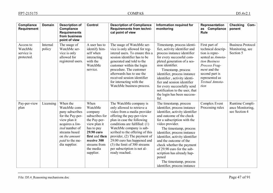
FP7-215175 COMPAS D5.4v2.1
File: D5.4_Reasoning mechanisms.doc Page 47 of 91
Compliance Requirement
Domain
Description of Compliance Requirements from business point of view
Control Description of Compliance Requirements from techni-cal point of view
Information required for monitoring
Representation as Compliance Rule
Checking Com-ponent
Access to WatchMe service is protected.
Internal policy
The usage of WatchMe ser-vice is only allowed for registered users.
A user has to identify him-self when interacting with the WatchMe service.
The usage of WatchMe ser-vice is only allowed for reg-istered users. To ensure this a session identifier has to be generated and told to the customer within the login procedure. The customer afterwards has to use the received session identifier for interacting with the WatchMe business process.
Timestamp, process identi-fier, activity identifier and process instance identifier for every successful com-pleted generation of a ses-sion identifier.
Timestamp, process identifier, process instance identifier , activity identi-fier and session identifier for every successfully send notification to the user, that the login has been success-ful.
First part of technical descrip-tion is repre-sented as Annota-tion Business Process Frag-ment and the second part is represented as Textual Annota-tion
Business Protocol Monitoring, see Section 5
Pay-per-view plan
Licensing When the WatchMe com-pany subscribes for the Pay-per-view plan it acquires a lim-ited number of streams based on the amount paid to the me-dia supplier.
When WatchMe company subscribes for the Pay-per-view plan it has to pay 29.90 euro first and then receive 300 streams from the media supplier.
The WatchMe company is only allowed to retrieve a video from a media provider offering the pay-per-view plan in case the following conditions are fulfilled: (1) WatchMe company is sub-scribed to the offering of this provider, (2) The payment of 29.00 euro has happened and (3) the limit of 300 streams per subscription is not al-ready reached.
The timestamp, process identifier, process instance identifier, activity identifier and outcome of the check for a subscription with the video provider.
The timestamp, process identifier, process instance identifier, activity identifier and the outcome of the check whether the payment of 29.90 euro for the sub-scription has already hap-pened
The timestamp, process identifier, process instance
Complex Event Processing rules
Runtime Compli-ance Monitoring, see Section 4

FP7-215175 COMPAS D5.4v2.1
File: D5.4_Reasoning mechanisms.doc Page 48 of 91
identifier, activity identi-fier, video provider identi-fier and paid amount of each successful payment.
The timestamp, process identifier, process instance identifier , video provider identifier, activity identi-fier, current number of streams already retrieved and the outcome of each check regarding the stream limit of 300.
The timestamp, process identifier, process instance identifier, activity identifier and video provider identi-fier of each successful re-trieval of a video stream.
Time-based plan
Licensing When the WatchMe com-pany subscribes for the Time-based plan it acquires any number of times any possible streams in a certain period, based on the amount paid to the media sup-plier.
When WatchMe company subscribes for the time-based plan it has to pay 89.90 euro first and then receive an unlimited number of times any available stream from the media
The WatchMe company is only allowed to retrieve a video from a media provider offering the time-based plan in case the following condi-tions are fulfilled: (1) WatchMe company is sub-scribed to the offering of this provider, (2) The payment of 89.90 euro has happened and (3) the 30 days period per subscription starting from the contract start date is not al-ready exceeded.
The timestamp, process identifier, process instance identifier, activity identifier and outcome of the check for a subscription with the video provider.
The timestamp, process identifier, process instance identifier, activity identifier and the outcome of the check whether the payment of 89.90 euro for the sub-scription has already hap-pened.
The timestamp, process
Complex Event Processing rules
Runtime Compli-ance Monitoring, see Section 4

FP7-215175 COMPAS D5.4v2.1
File: D5.4_Reasoning mechanisms.doc Page 49 of 91
supplier in a 30 days pe-riod starting from the con-tract start date.
identifier, process instance identifier, activity .identifier, video provider identifier and paid amount of each successful payment
The timestamp, process identifier, process instance identifier , video provider identifier, activity identi-fier, start date of the sub-scription contract and the outcome of each check re-garding the period of 30 days.
The timestamp, process identifier, process instance identifier, activity identifier and video provider identi-fier of each successful re-trieval of a video stream.
Composition permission
Licensing Only pre-defined combi-nations of video and audio providers are allowed due to the licenses specified by the video provider.
VideoTube can only have audios streams from AudioTube or QuickAudio. QuickVideo can only have audio streams from QuickAudio.
Only pre-defined combinations of video and audio providers are allowed to be assembled (videos from video provider VideoTube with audio streams from AudioTube or QuickAudio and videos streams from video provider QuickVideo are only allowed to be as-sembled with audio streams from audio provider QuickAudio.
The timestamp, process identifier, process instance identifier, activity identifier and video provider identi-fier of each successfully completed video retrieval.
The timestamp, process identifier, process instance identifier, activity identifier and audio provider identi-fier of each successfully completed audio retrieval.
The timestamp, process identifier, process instance
Complex Event Processing rules, because the Business Process Logic Fragment is glued into the business process during design time, cf. 3.3.1
Runtime Compli-ance Monitoring, see Section 4

FP7-215175 COMPAS D5.4v2.1
File: D5.4_Reasoning mechanisms.doc Page 50 of 91
identifier and activity iden-tifier of each successfully assembled video stream consisting of video as well as audio.
Delivery Rate QoS The WatchMe service must deliver in a fixed period of time the speci-fied number of URLs for downloading a stream.
The WatchMe service must deliver a valid URL at least in 90% of requests per cus-tomer sub-scription.
The WatchMe service must deliver correct results at least in 90 % of the requests for a URL for downloading a video with the corresponding title and in the corresponding language per customer sub-scription.
The timestamp, process identifier, process instance identifier, activity identi-fier, selected video title, selected language, of each successfully received video request.
The timestamp, process identifier, process instance identifier, activity identifier and video title of each suc-cessful video retrieval.
The timestamp, process identifier, process instance identifier, activity identifier and language of each suc-cessful audio retrieval.
The timestamp, process identifier, activity identifier and process instance identi-fier of each successfully assembled video stream consisting of video as well as audio.
The timestamp, process identifier, activity identifier and process instance identi-fier of each successful sending of media URL to
Complex Event Processing rules
Runtime Compli-ance Monitoring, see Section 4

FP7-215175 COMPAS D5.4v2.1
File: D5.4_Reasoning mechanisms.doc Page 51 of 91
the user. Moreover timestamp,
process identifier, process instance identifier, location within the process and rea-son has to be provided for every occurring fault within the WatchMe business process.
Availability QoS The WatchMe service must be available as specified to the customer in the contractual agreement of the subscription.
The WatchMe service must be available 99% of the time per customer subscription.
The WatchMe service has to be up and running as well as delivering correct results at least in 99% per customer subscription. The availability relates here to the search for available videos due to the corresponding title and the corresponding language pro-vided as input by the user.
The timestamp, process identifier, process instance identifier, activity identifier and search criteria of every successfully received me-dia search request from the user.
The timestamp, process identifier, process instance identifier, activity identi-fier, search criteria send to the corresponding provider, result from the correspond-ing provider of each suc-cess full request to both a video or audio provider.
The timestamp, process identifier, process instance identifier, activity identi-fier, provider identifier of video or audio provider and result list received from the corresponding provider for each successfully com-pleted search request from WatchMe company to
Complex Event Processing rules
Runtime Compli-ance Monitoring, see Section 4

FP7-215175 COMPAS D5.4v2.1
File: D5.4_Reasoning mechanisms.doc Page 52 of 91
video as well as audio pro-viders.
The timestamp, process identifier, process instance identifier, activity identifier and result list of available media after composition of results received from audio and video providers.
The timestamp, process identifier, activity identifier and process instance identi-fier of each successful completed sending of me-dia search results to the customer.
Moreover timestamp, process identifier, process instance identifier, location within the process and rea-son has to be provided for every occurring fault within the WatchMe business process.
Response time
QoS The response time for getting a URL of the requested media is as specified to the customer in the contractual agreement of the subscription.
The WatchMe service pro-vides a URL of the re-quested me-dia within 45 seconds to the customer.
The duration between receiv-ing of the data of selected video from the user (title and language) the URL to be retrieved for and the sending of the corresponding URL to the user must not exceed 45 seconds.
The timestamp, process identifier, process instance identifier and activity iden-tifier for each successful receiving of selected crite-ria (title and language) for media, which URL is in-tended to be downloaded.
The timestamp, process identifier, process instance
Complex Event Processing rules
Runtime Compli-ance Monitoring, see Section 4

FP7-215175 COMPAS D5.4v2.1
File: D5.4_Reasoning mechanisms.doc Page 53 of 91
identifier and activity iden-tifier of each successfully completed sending of a URL for downloading the requested media.
Moreover timestamp, process identifier, process instance identifier, location within the process and rea-son has to be provided for every occurring fault within the WatchMe business process.
Table 4 Required information for monitoring and mining of WatchMe scenario

FP7-215175 COMPAS D5.4v2.1
File: D5.4_Reasoning mechanisms.doc Page 54 of 91
3.4. COMPAS event model Currently the Apache ODE emits events in the Common Base Event (CBE) model developed by IBM. In the IBM Developer’s Guide [IBM04] (available at http://www.ibm.com/ develop-erworks/autonomic/books/fpy0mst.htm). At this website the concrete XML Schema, as well as, examples are provided. This CBE model is more expressive (and detailed) than the event model required in COMPAS (cf. Section 3.1) that is made up of source, target, timestamp etc. Hence, we can use it and express everything we want, as the COMPAS event model is a sub-set of this model. Therefore in COMPAS we plan to use those parts of the model required for compliance monitoring and mining.
The event shown in Listing 4 exemplifies the different identifiers which are used for the cor-relation of events with the activities and fragments contained in an instance of a particular process model. For each event that occurs in a process, particular identifiers are added that reveal the source of the event:
• The ID of the activity
• The ID of the fragment (if the activity is belonging to one)
• The ID of the surrounding <scope> construct
• The ID of the corresponding process instance
• The ID of the corresponding process model <?xml version="1.0" encoding="UTF-8"?>
<CommonBaseEvents xmlns="http://www.ibm.com/AC/commonbaseevent1_0_1" xmlns:xsi="http://www.w3.org/2001/XMLSchema-instance" xsi:schemaLocation="http://www.ibm.com/AC/commonbaseevent1_0_1 commonbaseevent1_0_1.xsd ">
<CommonBaseEvent creationTime="2001-12-31T12:00:00" elapsedTime="0" extensionName="Name" globalInstanceId="i0000000000000000000000000000040" localInstanceId="" msg="" priority="0" repeatCount="0" sequenceNumber="0" severity="0" version="">
<contextDataElements name="myContext" type="String"> <contextValue>PROCESS_NAME: {/processOrder}Ordering </contextValue> <contextValue>PIID:712433</contextValue> <contextValue>PMID:133</contextValue> <contextValue>PFID:3</contextValue> <contextValue>SID:73</contextValue> <contextValue>AID:13</contextValue> </contextDataElements>
<extendedDataElements name="" type="noValue"> <val-ues>valuesvalues</values> <children name="" type="noValue"> <values>valuesvalues</values> </children> </extendedDataElements>
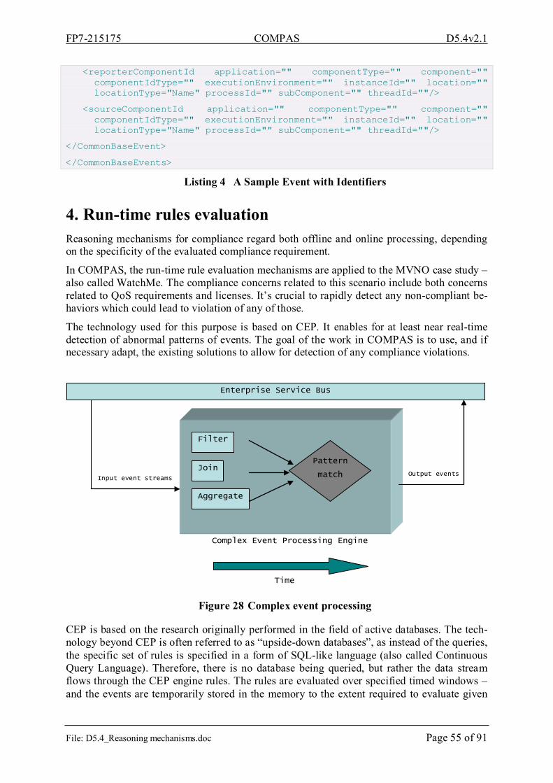
FP7-215175 COMPAS D5.4v2.1
File: D5.4_Reasoning mechanisms.doc Page 55 of 91
<reporterComponentId application="" componentType="" component="" componentIdType="" executionEnvironment="" instanceId="" location="" locationType="Name" processId="" subComponent="" threadId=""/>
<sourceComponentId application="" componentType="" component="" componentIdType="" executionEnvironment="" instanceId="" location="" locationType="Name" processId="" subComponent="" threadId=""/>
</CommonBaseEvent>
</CommonBaseEvents>
Listing 4 A Sample Event with Identifiers
4. Run-time rules evaluation Reasoning mechanisms for compliance regard both offline and online processing, depending on the specificity of the evaluated compliance requirement.
In COMPAS, the run-time rule evaluation mechanisms are applied to the MVNO case study – also called WatchMe. The compliance concerns related to this scenario include both concerns related to QoS requirements and licenses. It’s crucial to rapidly detect any non-compliant be-haviors which could lead to violation of any of those.
The technology used for this purpose is based on CEP. It enables for at least near real-time detection of abnormal patterns of events. The goal of the work in COMPAS is to use, and if necessary adapt, the existing solutions to allow for detection of any compliance violations.
Figure 28 Complex event processing
CEP is based on the research originally performed in the field of active databases. The tech-nology beyond CEP is often referred to as “upside-down databases”, as instead of the queries, the specific set of rules is specified in a form of SQL-like language (also called Continuous Query Language). Therefore, there is no database being queried, but rather the data stream flows through the CEP engine rules. The rules are evaluated over specified timed windows – and the events are temporarily stored in the memory to the extent required to evaluate given
Enterprise Service Bus
Input event streams
Filter
Join
Aggregate
Time
Complex Event Processing Engine
Pattern
match Output events

FP7-215175 COMPAS D5.4v2.1
File: D5.4_Reasoning mechanisms.doc Page 56 of 91
query. Thus, such technology enables for efficient massive parallel data streams processing for e.g.., monitoring purposes. The illustration of this process is shown in Figure 28.
The most interesting features of CEP are the support for temporal algebra and event pattern evaluation. The language not only allows for specification of standard SQL operators like filtering, grouping, aggregation or join, but also for evaluating these over specified period of time. Patterns allow for evaluation of expressions defined on specified pattern atoms (filter expressions, time-based event observers – e.g. time intervals between events occurrence). The expressions support logical operators, operators that control pattern subexpression repetition (e.g. every, until), and the most powerful temporal operators (-> “followed by” operator).
The CEP engine used for the WatchMe case study is Esper – which is a very reliable and scalable open source solution for event streams processing. The algorithms used in Esper are based on delta networks and state machines and only the changes made to processed data are communicated across object boundaries when it’s necessary.
Esper can serve both as an event consumer and event producer. Thus, as it is done in COM-PAS for WatchMe case study, it processes the low level events (BPEL events) and generates the higher level events notifying about compliance violations. The virtual medium used for the transportation of events is Enterprise Service Bus (ESB). Esper listens to the events on the ESB and emits events, which are results of the CEP reasoning mechanisms, back to it. The generated events carry the necessary information for the run-time dashboard to present any information about violation. In the current status of the project, the role of ESB is played by Apache ActiveMQ message broker [Apa09a]. ActiveMQ is not an ESB, but it’s widely used in many ESB implementations. At the current state of the project, the functionality offered by message broker are enough to run experiments on the monitoring components used in COM-PAS project.
5. Business protocol monitoring In this section, we present the business protocol monitoring component, which we use to monitor at runtime whether a running process conforms to the business protocol (i.e., the set of possible message flows) that can be derived from its process model. Business protocol monitoring lays the foundation for the runtime monitoring of business process fragments, which will extend the work described in this section (the respective details will follow in year 3 of the project). We first start with a short introduction to protocol monitoring, then we de-scribe the overall architecture of this component, and finally we present the monitoring lan-guage and show its properties.
Actual standards for specifying web service offers neither enough visibility on the processes it specifies nor suitable tools that could help designers statically analyze the behaviour of these processes that they manage to make communicate in a correct manner. This is why the au-thors in [BCT04] investigated a way to represent the protocol that two services must follow to interact correctly. This was called business protocol since it represents the allowed conversa-tions between a requester and a provider in terms of messages according to the states that they reached in the local execution of their respective business processes.

FP7-215175 COMPAS D5.4v2.1
File: D5.4_Reasoning mechanisms.doc Page 57 of 91
Figure 29 WatchMe Business protocol
Figure 29 shows the business protocols of WatchMe business process. The protocol is repre-sented graphically as a Harel Statechart [Har87]. The states have special significance to the business process being modelled since they denote the steps it passes through during its exe-cution. The transitions are labelled with the name of the messages that are sent or received by a service. Messages are assigned polarity signs, (+) when they are consumed by a service and (-) when they are produced by it.
5.1. Protocol monitoring component (the overall architecture) Figure 26 shows a system (process to monitor) which exchanges SOAP messages with exter-nal partners. So, the aim is to check the correct execution of this system at run time and ana-lyze its performance.
All incoming or outgoing messages are captured by Business protocol monitoring. On the basis of the specified requirements, business protocol monitor component checks the execu-tion and return checking results or statistical indicators, and may be act on the incoming or outgoing messages or invoke action on the process instance.
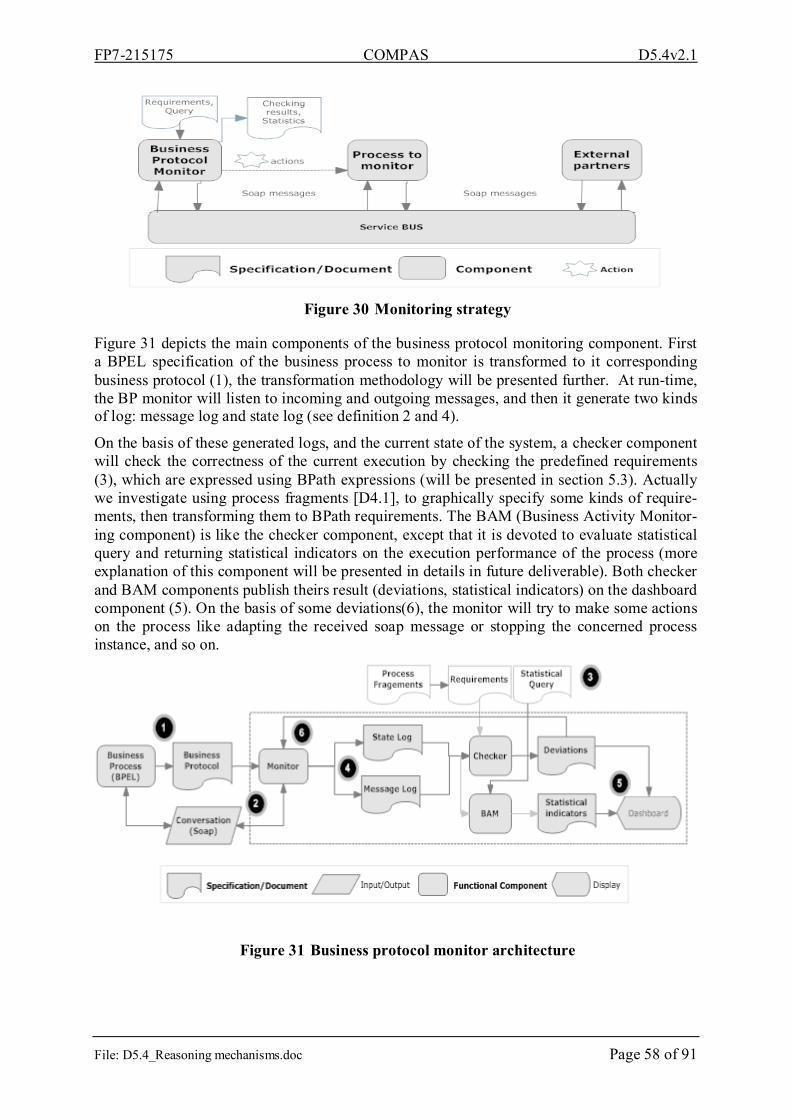
FP7-215175 COMPAS D5.4v2.1
File: D5.4_Reasoning mechanisms.doc Page 58 of 91
Figure 30 Monitoring strategy
Figure 31 depicts the main components of the business protocol monitoring component. First a BPEL specification of the business process to monitor is transformed to it corresponding business protocol (1), the transformation methodology will be presented further. At run-time, the BP monitor will listen to incoming and outgoing messages, and then it generate two kinds of log: message log and state log (see definition 2 and 4).
On the basis of these generated logs, and the current state of the system, a checker component will check the correctness of the current execution by checking the predefined requirements (3), which are expressed using BPath expressions (will be presented in section 5.3). Actually we investigate using process fragments [D4.1], to graphically specify some kinds of require-ments, then transforming them to BPath requirements. The BAM (Business Activity Monitor-ing component) is like the checker component, except that it is devoted to evaluate statistical query and returning statistical indicators on the execution performance of the process (more explanation of this component will be presented in details in future deliverable). Both checker and BAM components publish theirs result (deviations, statistical indicators) on the dashboard component (5). On the basis of some deviations(6), the monitor will try to make some actions on the process like adapting the received soap message or stopping the concerned process instance, and so on.
Figure 31 Business protocol monitor architecture

FP7-215175 COMPAS D5.4v2.1
File: D5.4_Reasoning mechanisms.doc Page 59 of 91
In the following we will present some formal definitions which provide more clarity to busi-ness protocol monitoring component and are relevant to understanding the monitoring lan-guage and its capacity, which will be presented further.
Definition 1:
A Business Protocol, as already defined, specifies the potential sequencing of messages ex-changed by a particular partner with its other partners to achieve a business goal. It can be formally defined as a:
P = (S, s0, F,M, T ) Where:
− S is the set of states of the protocol,
− M is the set of messages supported by the service,
− s0 is the initial state, and
− F represents the finite set of final states.
− T ⊆ S×S×M×{+,-}is the set of transitions,
− A transition from state si to state sj triggered by the input message m is denoted by the triplet (si,m,+, sj).
− A transition from state si to state sj triggered by the output message m is denoted by the triplet (si,m,-, sj).
Log component is an important element for any monitoring system. In Protocol monitoring component we have two different kind of log component: Message Log, and State Log.
Message log component save messages conversation historic between different instance of the process and external its partners..
Definition 2:
A message log ML is a collection of entries ml = (Insid, messageName, messageValue, t), where: Insid is an Instance identifier of the process instance concerned with the message, messageName is the name of the exchanged message, messageValue is the value of the mes-sage if-self and t is a timestamp.
State Log component is an additional log component, which serve to save the sequence of protocol states in correspondence to the exchanged messages between the process and others partners.
Definition 3:
States Log (SL) is a set of protocol execution paths. Each protocol execution Path Pi is a time ordered list of business protocol state PS (Appid, Insid, s, t). Appid, InsId is a unique identi-fier, s∈S, and t is a timestamp. Plus two specific tuples: (Appid, Empty, Application, tMax) and (Insid, Instance, tMax); where, tMax is timestamp, ∀(Appid, Insid, s, t) ∈Pi: t<=tMax.
Each business protocol state, saved in the SL is like snapshoot of the current state, of an in-stance of a business process in execution at a time Ti. It gets a view on the current value of

FP7-215175 COMPAS D5.4v2.1
File: D5.4_Reasoning mechanisms.doc Page 60 of 91
different messages on an instance of the business process at run-time, which is defined by the following valuation function.
Definition 4:
A valuation function θ define the relation between the stored state in the States Log and the stored messages entries on the Messages Log:
θ(si,mi,ti)= messageValue /∃ (Insid, messageName, messageValue, tj) ∈ML and ( tj<ti) ˄( ∀ (mi, tk)∈ML: tk<tj or tk>ti).
5.2. Transformation of BPEL business processes to business pro-tocol
In the following, we will present a methodology for transforming a BPEL specification to a business protocol automaton. For transformation purpose, we consider BPEL specification as stated in [AAA+07]. Then, we analyze a constructive manner by generating segments of the automaton corresponding to the basic activities and then combine the resulting segments by looking into the structured activities to which they belong.
5.2.1. Transformation of basic activities
For each activity represented in BPEL syntax; we give its corresponding automaton segment definition. States named as q indexed with an integer i are just used for representation and could be renamed.
Invoke activity: <invoke partnerLink="pl" portType="pt" operation="op" inputVariable="inVar" outputVariable="outVar"/>
Is transformed into the following segment of automaton
({qi , qi+1 , qi+2 }, qi , {qi+2 },{ pl#pt#op,+,-},{(qi , pl#pt#op,−, qi+1),(qi+1 , pl#pt#op,+, qi+2)}
Here, qi+1 is an intermediate state meaning that a message has been sent from a process to one of its partners and is blocked waiting for a message to be returned to change its state.
Receive activity:
The receive activity which waits for a message that will be consumed takes the form: <receive partnerLink="PL" portType="PT" operation="op" variable="var">
It is transformed to the automaton defined by:
({qi, qi+1 }, qi , {qi+1 },{ pl#pt#op,+,-}, {(qi, pl#pt#op,+, qi+1)})
Reply activity: <reply partnerLink="PL"portType="PT"operation="op" variable="Var">
and its automate
({qi , qi+1 }, qi , {qi+1 },{ pl#pt#op,+,-}, {(qi , pl#pt#op,−, qi+1)})
Other activities like: wait, exit, empty, throw and rethrow are defined in the BPEL specification but not all are relevant. Wait which makes the process wait for a pre-

FP7-215175 COMPAS D5.4v2.1
File: D5.4_Reasoning mechanisms.doc Page 61 of 91
cise moment or until a certain time could be mapped to a business protocol using temporal transitions defined in [BCP+05] that are implicit transitions to be taken when the time constraint defined for them is satisfied. Exit is mapped to a transition leading to a final state.
5.2.2. Transformation of structured activities
Structured activities are used to link between basic activities following a logic we have in mind at design-time. This is done using different constructs such as flow which expresses that the activities defined in its scope run concurrently, sequence which links between basic or structured activities that are designed to run sequen-tially, if-then-else express conditional branching to a point in the process, while and repeat-until are used to loop through a set of activities and pick waits for a suitable message to trigger the corresponding action or a default action if time overruns. As done for the basic activities, we assign for each type of activity given in BPEL syn-tax its corresponding automaton definition.
5.3. Monitoring language In this section we will present a monitoring language called BPath, which allows expressing some kinds of requirements and expressing some queries on the business process execution.
This language is mainly based on extending XPath language [W3C1], by:
• External variables definition.
• Temporal logic support. Reader may refer to [Har03] for clear introduction to XPath language and its usage.
External variable definition allows defining variables within XPath expression, which its val-ues are computed by external function, defined in the evaluation framework. So, this technical extension for instance allows accessing to different data sources (DB, Service, Process…) during the evaluation of an XPath expression.
For instance, let’s consider the following XML document, which correspond to a serialisation of a state log generated by the business protocol monitoring component, when it monitor the WatchMe business process.
<state name=’s1’ Appid=’3452334’ Insid=’343’ t=’66868’ > <state name=’s2’ Appid=’3452334’ Insid=’343’ t=’66869’ >
<state name=’s3’ Appid=’3452334’ Insid=’343’ t=’66879’ > .. <state>
<state> <state>
Listing 5 State log (xml serialisation)
The following listing shows use of external variable to access to some external data (the re-quested movie in the current state). <!--valuation function, defined in the host framework-->
<!--return the value of an external variable ‘SearchRequest’-->

FP7-215175 COMPAS D5.4v2.1
File: D5.4_Reasoning mechanisms.doc Page 62 of 91
<!-- on the current context node. -->
ValueOf(XmlNode CurrentNode, string VarName){
//do some things (access to db, log, and invoke service...)
Object result=...
return result;
}
<!--valid XPath expression (somewhere in the state child’s nodes we have searchrequest equal to ‘prison break’) -->
.//state[$SearchRequest=’Prison break’]
Listing 6 BPath external variables definition
The second extension introduces linear temporal logic operators as extended XPath functions, LTL was introduced by [Pnu77], which can be used to express a wide range of interaction properties. LTL define four temporal operators:
• X(α): The LTL formula α is true in the next time,
• F(α): The LTL formula α is true sometimes in the future
• G(α): The LTL formula α always true now, and in the future
• U (α, β): The LTL formula α is true until the LTL formula β is true.
LTL is a well-accepted linear-time temporal logic used for specifying properties of infinite traces. However, one has to interpret their semantics with respect to finite prefixes as they arise in observing actual systems [LS09], for this reason we have adopted the same semantic as it is described in [BLS07].
The following listing shows an example of BPath expression using temporal logic operator.
<!-- $responseTime, $processingTime, $DeliveryRate are external variables, theirs value are computed in the framework evaluating the XPath expression -->
<!-- always the response time should be less than 15 in all state child’s nodes.-->
G(state[$responseTime<15])
<!-- Delivery Rate>n until processing time>m starting from the current state node-->
U($DeliveryRate >n, $processingTime >m)
Listing 7 BPath requirements definition

FP7-215175 COMPAS D5.4v2.1
File: D5.4_Reasoning mechanisms.doc Page 63 of 91
5.4. Monitoring language properties Business protocol monitoring component offers a various monitoring characteristics, in the following we present some of them:
1 Dynamic requirement specification: by using BPath language, which is an interpretable language (based on XPath), requirements to check can be specified during the execution of the process.
2 Temporal requirements checking: as presented in the precedent section, temporal re-quirements can be specified and checked using BPath language.
3 Monitoring Data: by using BPath (use of external variables definition) data can be col-lected from different sources: directly from SOAP message or external data… and indi-rectly from the published data on the bus such as process data and process low level events.
4 Flexible monitoring: monitoring can be done in flexible way:
• In intrusive way: by blocking the business process at running until the checking is done, this ensure detecting an anomalous situation as soon as the data indicating the anomaly have been collected. In this case the monitor has a real view on the current state of the process.
• Post-mortem monitoring: in contrast to the precedent way, this type of monitoring does not block the process at run-time. So, the monitoring activity is completely independent from the process, and do not affect the performance of the execution. But, in this case, the real state of the process may be in advanced state, than the one observed by the business protocol monitoring component. A simple and an in-dependent way from any process engine technology to block the process at run-ning, can be done by instrumenting the BPEL process (by adding some code into its XML code), in transparent way, just before building -time.
6. Assessing and reporting on compliance This section defines the concept of Key Compliance Indicators (KCIs) for the purpose of as-sessing and reporting at a glance on the compliance state of a company. For that, we introduce the KCI concepts and how they are computed and show a list of KCIs that fit in the aforemen-tioned scenario.
6.1. Key Compliance Indicators (KCIs) Well known best practices and quality standards, such as Cobit [Cob05], CMMI [SEI09], PMBOK [PMI04], recommend the use of indicators to control, measure (quantify) and repre-sent (qualify) organizations’ performance against business goals in an efficiently way. The periodical process of measuring, controlling and evaluating indicators provides a performance view to assist decision making at different organizational levels.
The diagram in Figure 32, proposed by Cobit 4.0 and adapted here in compliance terms, clearly expresses the relationship among business processes, goals and indicators. In general, indicators are computed out of a variety of data and by means of different functions, ranging from the lowest activity level to the highest business level, to verify if business goals are achieved. In the context of compliance assessment, more specifically, indicators can be re-

FP7-215175 COMPAS D5.4v2.1
File: D5.4_Reasoning mechanisms.doc Page 64 of 91
lated to the encountered violations and the number of compliant or non-compliant instances of a process or activity. Based on that, a Key Compliance Indicator (KCI) is a numeric value used to quantify compliance performance, in a pre-determined time interval and compared against internal targets in order to give evidence for the level of compliance performance.
Understand which are the
system vulnerabilities
Number of instances that
started noncompliant
downloads
Detect and resolve sources of noncompliant
downloads
Number of noncompliant
donwloads (violations)
Monitor the downloads’ compliance
-Total number of donwloads-Total of noncompliant downloads
Be compliant with Copyright
compliance sources
% of compliant downloads
Business GoalIT GoalProcess GoalActivity Goal
is measured by is measured by is measured by is measured by
Mea
sure
Ach
ieve
men
t
Impr
o ve
a nd
Re a
l ing
Define Goals
Drive Performance
Key Compliance Indicators (KCIs)
Figure 32 Relationship among process, goals and indicators (adapted from [Cob05])
According to Cobit 4.0 [Cob05], effective indicators (sometimes also called metrics) should meet the following characteristics:
− Indicators should have a high insight-to-effort ratio (i.e., insight into performance and achievement of goals compared to the effort necessary to capture them);
− They should be comparable internally (e.g., against reference values or over time); − They should be comparable externally irrespective of enterprise size or industry; − It’s better to have a few good indicators than a long list of low-quality indicators; − Indicators should be easy to measure and not be confused with targets (meaning that
people try to optimize individual indicator values, rather than concentrating on the core business).
For the communication of indicator values, we typically define taxonomies (e.g., low, me-dium, high) and use colors (e.g., red, yellow, green) for their intuitive visualization. For ex-ample, Figure 33 illustrates how to abstract KCIs using taxonomies and colors.
0% ≤ %OfCompliantDownloads ≤ 50% = Low =
51% ≤ %OfCompliantDownloads ≤ 69% = Medium =
70% ≤ %OfCompliantDownloads ≤ 100% = High = Figure 33 How to abstract KCIs: visual alert levels
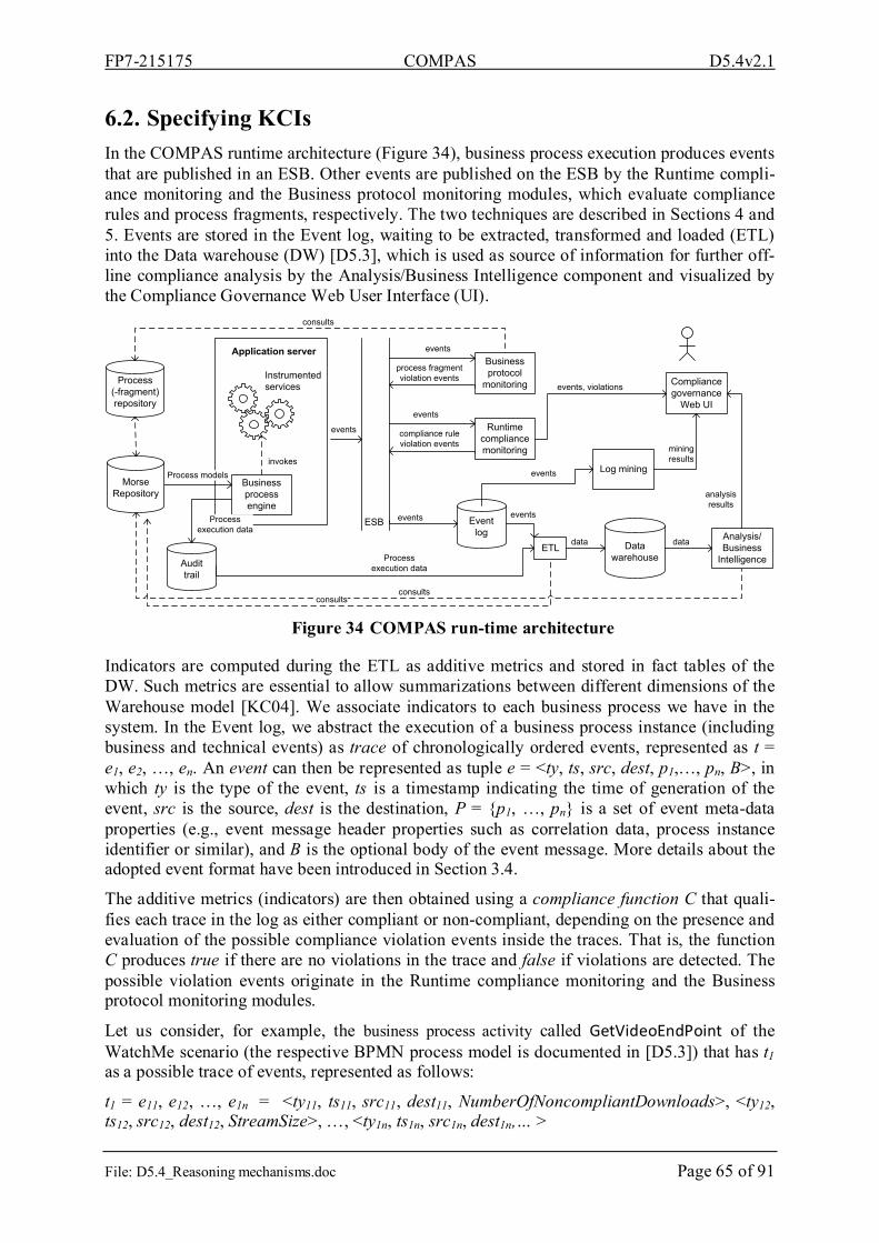
FP7-215175 COMPAS D5.4v2.1
File: D5.4_Reasoning mechanisms.doc Page 65 of 91
6.2. Specifying KCIs In the COMPAS runtime architecture (Figure 34), business process execution produces events that are published in an ESB. Other events are published on the ESB by the Runtime compli-ance monitoring and the Business protocol monitoring modules, which evaluate compliance rules and process fragments, respectively. The two techniques are described in Sections 4 and 5. Events are stored in the Event log, waiting to be extracted, transformed and loaded (ETL) into the Data warehouse (DW) [D5.3], which is used as source of information for further off-line compliance analysis by the Analysis/Business Intelligence component and visualized by the Compliance Governance Web User Interface (UI).
Instrumented services
ESB
Application server
Process (-fragment) repository
consults
Data warehouse
Analysis/ Business
Intelligence
consults
Business process engine
Audit trail
Process execution data
ETL
Event log
Log mining
Compliance governance
Web UI
Runtime compliance monitoring
Business protocol
monitoring
consults
Process execution data
invokes
events
events
compliance ruleviolation events
process fragmentviolation events
events
mining results
analysis results
datadata
events
events
events, violations
events
Process modelsMorse
Repository
Figure 34 COMPAS run-time architecture
Indicators are computed during the ETL as additive metrics and stored in fact tables of the DW. Such metrics are essential to allow summarizations between different dimensions of the Warehouse model [KC04]. We associate indicators to each business process we have in the system. In the Event log, we abstract the execution of a business process instance (including business and technical events) as trace of chronologically ordered events, represented as t = e1, e2, …, en. An event can then be represented as tuple e = <ty, ts, src, dest, p1,…, pn, B>, in which ty is the type of the event, ts is a timestamp indicating the time of generation of the event, src is the source, dest is the destination, P = {p1, …, pn} is a set of event meta-data properties (e.g., event message header properties such as correlation data, process instance identifier or similar), and B is the optional body of the event message. More details about the adopted event format have been introduced in Section 3.4.
The additive metrics (indicators) are then obtained using a compliance function C that quali-fies each trace in the log as either compliant or non-compliant, depending on the presence and evaluation of the possible compliance violation events inside the traces. That is, the function C produces true if there are no violations in the trace and false if violations are detected. The possible violation events originate in the Runtime compliance monitoring and the Business protocol monitoring modules.
Let us consider, for example, the business process activity called GetVideoEndPoint of the WatchMe scenario (the respective BPMN process model is documented in [D5.3]) that has t1 as a possible trace of events, represented as follows:
t1 = e11, e12, …, e1n = <ty11, ts11, src11, dest11, NumberOfNoncompliantDownloads>, <ty12, ts12, src12, dest12, StreamSize>, …, <ty1n, ts1n, src1n, dest1n,… >

FP7-215175 COMPAS D5.4v2.1
File: D5.4_Reasoning mechanisms.doc Page 66 of 91
Among the events of the trace, we find event e1, that carries a parameter NumberOfNonCom-pliantDownloads representing the number of downloads that performed in the context of the GetVideoEndPoint process and that exceed the “n allowed number of possible streams at a price p” stated by the Pay-per-view plan compliance requirement (described in Table 1). We can use this knowledge, for instance, to compute a KCI reporting on WatchMe’s compliance with its licenses. For example, we can express the Percentage of Noncompliant Downloads according to the following equation that is computed over all the traces of the GetVideoEnd-Point process we have in our DW:
(%)100
%∑
∑ ∗=
wnloadsNumberOfDoDownloadsncompliantNumberOfNo
adsiantDownloOfNoncompl i
An example of QoS KCI can be done using the StreamSize attribute, which stores the stream size of downloads performed by the GetVideoEndPoint process. Based on that and on the process timestamps t1 (end of streaming) and t0 (start of streaming), it is possible to compute a KCI named Delivery Rate to control if the delivery rate is compliant with the contract plan signed with the WatchMe consumers.
)/(1
01
sKbpstt
StreamSizereamsNumberOfSt
teDeliveryRaii
i∑ −=
The KCIs are computed after the ETL, more precisely during the Warehouse cube generation. In that moment, the indicators are calculated taking into account all possible combinations of dimensions. For example, in the Windows SQL Server platform such indicators are computed using Multidimensional Expressions (MDX) [Sql09]. Thus, end-users can use drill-down and slice/dice features to visualize indicators in different summarization levels and perspectives (e.g., all noncompliance downloads of the pay-per-view plan done in the first two months of 2009).
6.3. KCIs in the WatchMe scenario In order to monitor compliance performance against business goals a set of indicators were stated based on the compliance requirements of the WatchMe scenario. Table 5 shows such indicators together with their respective goals (i.e., compliance with a specific compliance requirement), equations, measurement unit, and organization target. In fact, there is no stan-dard set of KCIs, each organization has to define and specify a concise set the indicators ac-cording to their internal compliance requirements, needs, resources and interests.
Indicator B. Goal Equation Unit Organizational Target
% of Com-pliance
Be compliant with Copy-right Laws ∑
∑ ∗−=
cesInsonscesViolatiIns
Compliancetan
100tan100%
%
≤ 94% = Low ≥95% and ≤ 98%= Medium ≥99% = High
Penalties Reduce pen-alty expenses PenaltyonscesViolatiInsPenalties ∗=∑ tan U$
≤ 500 = Low ≥501 and ≤ 690= Medium ≥691 = High
% of stake-holders who understand IT policy
Disseminate internal com-pliance poli-cies
∑∑−=
rsstakeholdeinrsComp.TraStakeholde
100rsstakeholde%Compliant
% ≤ 30% = Low ≥31% and ≤ 49%= Medium ≥50% = High
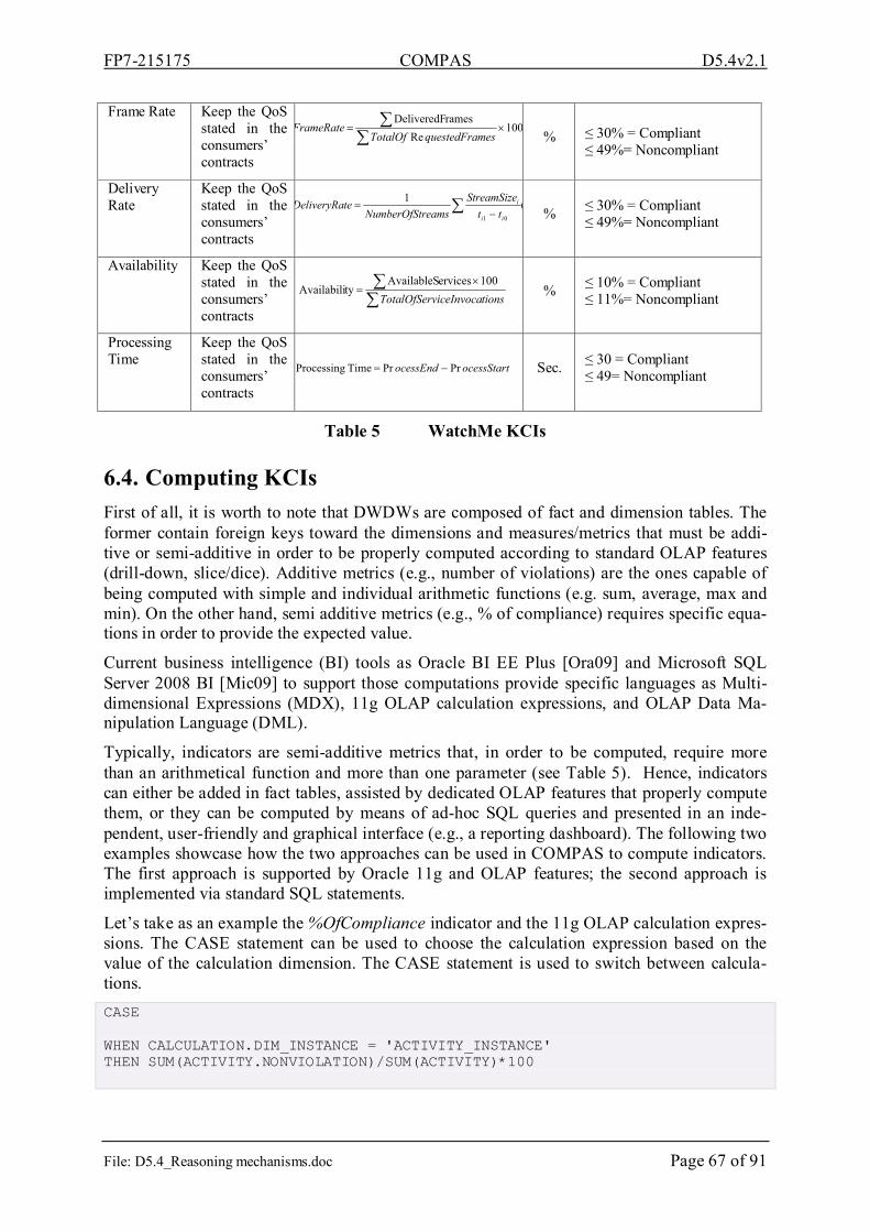
FP7-215175 COMPAS D5.4v2.1
File: D5.4_Reasoning mechanisms.doc Page 67 of 91
Frame Rate Keep the QoS stated in the consumers’ contracts
100Re
ramesDeliveredF×=
∑∑
mesquestedFraTotalOfFrameRate
% ≤ 30% = Compliant
≤ 49%= Noncompliant
Delivery Rate
Keep the QoS stated in the consumers’ contracts
(1
01 ttStreamSize
reamsNumberOfStteDeliveryRa
ii
i∑ −=
% ≤ 30% = Compliant
≤ 49%= Noncompliant
Availability Keep the QoS stated in the consumers’ contracts
∑∑ ×
=tionsviceInvocaTotalOfSer100ervicesAvailableS
tyAvailabili
% ≤ 10% = Compliant ≤ 11%= Noncompliant
Processing Time
Keep the QoS stated in the consumers’ contracts
ocessStartocessEnd PrPrTime Processing −= Sec. ≤ 30 = Compliant ≤ 49= Noncompliant
Table 5 WatchMe KCIs
6.4. Computing KCIs First of all, it is worth to note that DWDWs are composed of fact and dimension tables. The former contain foreign keys toward the dimensions and measures/metrics that must be addi-tive or semi-additive in order to be properly computed according to standard OLAP features (drill-down, slice/dice). Additive metrics (e.g., number of violations) are the ones capable of being computed with simple and individual arithmetic functions (e.g. sum, average, max and min). On the other hand, semi additive metrics (e.g., % of compliance) requires specific equa-tions in order to provide the expected value.
Current business intelligence (BI) tools as Oracle BI EE Plus [Ora09] and Microsoft SQL Server 2008 BI [Mic09] to support those computations provide specific languages as Multi-dimensional Expressions (MDX), 11g OLAP calculation expressions, and OLAP Data Ma-nipulation Language (DML).
Typically, indicators are semi-additive metrics that, in order to be computed, require more than an arithmetical function and more than one parameter (see Table 5). Hence, indicators can either be added in fact tables, assisted by dedicated OLAP features that properly compute them, or they can be computed by means of ad-hoc SQL queries and presented in an inde-pendent, user-friendly and graphical interface (e.g., a reporting dashboard). The following two examples showcase how the two approaches can be used in COMPAS to compute indicators. The first approach is supported by Oracle 11g and OLAP features; the second approach is implemented via standard SQL statements.
Let’s take as an example the %OfCompliance indicator and the 11g OLAP calculation expres-sions. The CASE statement can be used to choose the calculation expression based on the value of the calculation dimension. The CASE statement is used to switch between calcula-tions. CASE WHEN CALCULATION.DIM_INSTANCE = 'ACTIVITY_INSTANCE' THEN SUM(ACTIVITY.NONVIOLATION)/SUM(ACTIVITY)*100

FP7-215175 COMPAS D5.4v2.1
File: D5.4_Reasoning mechanisms.doc Page 68 of 91
WHEN CALCULATION.DIM_INSTANCE = 'BP_INSTANCE' THEN SUM(BP_INSTANCE.NONVIOLATION)/SUM(BP_INSTANCE)*100 WHEN CALCULATION.DIM_INSTANCE = 'SERVICE_INSTANCE' THEN SUM(SERVICE.NONVIOLATION)/SUM(SERVICE)*100 ELSE NULL END
Listing 8 Case statement to compute the %OfCompliance indicator
The same indicator (e.g., for the case of business processes) can also be computed with the SQL statements listed below (details about the tables and attributes are available in [D5.3]). CompliantProcesses = SELECT COUNT(BP_Instance)
FROM F_ComplianceEvaluation
WHERE IsViolation = 0;
TotalProcesses = SELECT COUNT(BP_Instance)
FROM F_ComplianceEvaluation;
%OfCompliance = CompliantProcesses / TotalProcesses * 100
Listing 9 SQL statements to compute %OfCompliance indicator
7. Root cause analysis of runtime compliance violations Indentifying and understanding the causes of exceptions that occur during runtime can help IT experts and business managers to understand how to avoid future violations of compliance constraints and, hence, decrease risk. For example, knowing that a large part of QoS viola-tions are due to a specific audio provider presenting frequent connection problems, which compromises the operativeness of WatchMe (e.g., its delivery rate), would allow WatchMe to cancel the contract with the audio provider and to switch to a more reliable one.
Typically in the BP context, root cause analysis is based on fine-grained logging techniques and sophisticated data mining techniques [BBL07][GCC+04][NBZ06]. Business data (e.g., events from running process instances) are collected, structured and stored in a data ware-housing; then, selected data subsets are prepared to be used as input for the mining algo-rithms. Data mining means looking for structured patterns in huge amounts of data [WF05]. Such patterns are typically not known a priori and are, hence, represent new, valuable infor-mation in the hand of the expert looking at them. For example, data mining algorithms could discover that processes executed by new employees that did not attend the required training sections are likely to be noncompliant; hence, they must be advised to register for the next round of training. The aim of data mining in the context of root cause analysis is therefore to identify and explain why and how past exceptions happened and also to predict future ones. Based on that information, managers and IT experts can then fix or prevent noncompliant situations.
In COMPAS, root cause analysis of runtime compliance violations follows a similar ap-proach: the Analysis/Business Intelligence component (Figure 34) retrieves from the ware-

FP7-215175 COMPAS D5.4v2.1
File: D5.4_Reasoning mechanisms.doc Page 69 of 91
house the required business process execution data in form of events and uses them in order to feed our data mining algorithms. Next, we describe how we specifically adopt the classifica-tion technique and decision trees in order to support root cause analysis. We contextualize the concepts and examples in the WatchMe scenario and discuss some implementation details.
7.1. Classification and decision trees Among the data mining approaches, classification (i.e., decision trees, neural and Bayesian nets) is the most widely adopted and indicated approach to address root cause analysis in BP and software development, as we can see in [GCC+04] [GRR+08] [NBZ06]. According to Han & Kamber [HK01], classification is a two-step process to predict categorical labels based on discrete, categorical, or nominal values.
In the first step of the classification process, the model/classifier needs to be configured by means of classes or concepts. Each class is composed of a set of database tuples arranged in a unique row and containing a class label attribute. For that, the raw data are analyzed by a data preparation activity, in which attributes of interest are defined (attributes that measures dif-ferent and individual aspects of an object instance [WF05]). Such activity is considered the most challenging and time consuming task in the whole classification process [HK01][TSK06]. Usually, the information of a specific instance is scattered over different tables in the warehouse, so that they need to be consolidated and represented as a unique row of a table. This typically requires aggregating data, mitigating inconsistency problems, reduc-ing the size of data, selecting attributes of interest, creating new attributes, transforming at-tributes, and discretization [TSK06]. Regarding to the class label attribute, it is manually filled with label values that represent the expected results of the classification model (e.g., the class label is compliance status and the label values are true or false)). At this step all attrib-utes, of interest and manually filled with the classification result, are referred to as samples, examples or objects, and compose the training data set.
The existence of provided class labels characterizes classification as a supervised learning, in which the classifier learns with the training set. Usually, the learned model is expressed by means of classification rules, decision trees, or mathematical equations. For examples, given an event log, classification rules can learn to identify noncompliant events, and afterwards such rules can be used to predict future noncompliant events and to understand better their behavior.
In the second step, the model/classifier trained in the previous step is used to perform the ac-tual classification. However, first of all it is necessary to estimate the predictive accuracy of the model. The accuracy is the percentage of training samples correctly classified by the model, to measure that each known class label of the sample is compared with the class learned by the model and the results are computed. Acceptable accuracy varies according to the problem and the environment where the classifier is used. In many practical data mining applications, success is measured more subjectively in terms of how acceptable are to the user the learned description, in terms of rules or the decision trees [WF05]. Moreover, at this step obvious results are achieved, so the output needs to be refined in order to obtain useful and satisfactory results. Finally, when the model is considered useful, independently of the evaluation method, it can be used to classify data tuples that have unknown class label attrib-utes.
Classification algorithms are based on a divide-and-conquer approach in order to learn a par-ticular class of attributes from a set of independent instances. Their output is typically ex-pressed as a decision tree (Figure 35). In that tree, each node tests/compares a particular at-

FP7-215175 COMPAS D5.4v2.1
File: D5.4_Reasoning mechanisms.doc Page 70 of 91
tribute with a constant, other attributes or the results of a function. The leaves express the re-sults of the classification applied on the attributes that reached the leaf. The numeric values in the leaves show the accuracy of the classifier: the first value indicates the number of inputs that are correctly classified, and the second value expresses the number of inputs that are in-correctly classified. To classify a new instance, the tree is traversed top-down according to the values of the instance’s attributes until reaching a leaf. The value of the reached leaf repre-sents the output of the classification.
Figure 35 Example of a Decision Tree
In order to understand the root cause of a given compliance violation, it is possible to traverse the tree bottom-up: if, for instance, we want to understand why the process classified in Fig-ure 35 is noncompliant, we start from the lower-left leaf, then we track all the labels of the arcs (the decisions) that connect the nodes we traverse in order to reach the root of the tree (the QuickVideo node and the Time-based node). As a result we can derive that each time we do not use a time-based contract and the video provider is not QuickVideo, then the process violates some compliance constraint.
If instead we want to use the decision tree to predict future situations (e.g., at the begin of the business process), it is possible to derive a set of rules directly from the decision tree by gen-erating a rule for each leaf: the prediction is the value of the leaf, the condition is the conjunc-tion of all the tests encountered on the path from the root to the leaf (“The antecedent of the rule includes a condition for every node on the path from the root to that leaf, and the conse-quent of the rule is the class assigned by the leaf” [WF05]). From the tree in Figure 35 we can, for example, derive the following set of rules:
if (CRequirement = “Time-based”) then Compliant if (CRequirement <> “Time-based”) and (VideoProvider = “QuickVideo”) then Compliant if (CRequirement <> “Time-based”) and (VideoProvider <> “QuickVideo”) then Noncompliant
The rules are particularly interesting for the automatic prediction of compliance states. How-ever, decision trees as a concise and effective representation of the rules have the advantage that they can easily be visualized to and understood by users. Hence, trees are an effective means to convey the discovered knowledge to non-experts (e.g., clients, stakeholders, CIOs) in order to support decision making.
7.2. Implementation The implementation of classification and the derivation of decision trees in COMPAS lever-ages on Weka 3.0 (Waikato Environment for Knowledge Analysis) [Wek09], a popular and open-source workbench for data mining, and the C4.5 classification algorithm. Weka is easy to use and integrate into the COMPAS compliance assessment logic. It requires as input a file in a proprietary format called ARF (attribute-relation file), basically an ASCII file describing

FP7-215175 COMPAS D5.4v2.1
File: D5.4_Reasoning mechanisms.doc Page 71 of 91
a list of instances sharing a set of attributes. At the beginning of the file are defined all the attributes and their respective type, in the same place is state the class attribute with all possi-ble values in curly brackets parentheses, like @ATTRIBUTE class {Yes, No} [Att09]. In order to feed Weka’s classification algorithm with COMPAS data, we export the necessary event data from the DWDW in ARF.
In this section, we are interested in discovering root causes of noncompliant business process instances based on business execution data, differently from the root cause analysis approach regarding design-time violations presented in Section 2. More specifically, we want to iden-tify knowledge like: 80% of the top ten video clip downloads exceed the value considered compliant by the delivery rate indicator, very likely due to the high number of requests regis-tered at the end of the weekend. Hence, the business expert can relate these results with the fact that MTV publishes its top ten lists every weekend. Or, consumers that include family members in their plans usually exceed the number of downloads allowed by their plan. In order to such kind of results, we perform the two steps of the classification process as follows.
First Step: The attributes of interest based on data events are obtain from the DW by means of SQL queries. Then, a set of methods are applied in order to generate a table with one unique row (tuple) per event instance, as illustrated in Figure 36.
DW Data Preparation Routine
SQL queries
Data eventsData events
1258282345968;55;ServiceInvocation;45;1;PRISONBREAK;AudioTube##1258282345979;26;ServiceInvocation;26;1;LOST;VideoTube##....
Data Preparation
Tuples
Figure 36 Details of the Data Preparation
When the generation of tuples is concluded, the test sample rows can be classified and their results added in from of class label attributes. For instance, in our example of the WatchMe scenario the class label attributes contain values Yes or No, according to compliance status of the event. Such label is aligned with the COMPAS objective that is focused on monitoring service compliance. Table 6 illustrates an example of tuples as we can find them in our train-ing set, in which only one event is compliant and the rest are not. This classification is repre-sented by values of the Class column. For presentation purposes, we only show some example rows and columns of the table, while other are hidden, e.g., EventName (PayPer-ViewEventListener, TimeBasedPlanEventListener), Source (CEP, Monitoring Protocol), Role (Consumer, Provider), Actor (Bob), UUID, ComplianceSource (License of the Pay-per-view contract), ComplianceRisk (Interruption of video provision for one week), ComplianceRe-quirement (Videos from QuickVideo provider can only be merged with audio streams from QuickAudio provider), ComplianceRule (see Section 3.2).

FP7-215175 COMPAS D5.4v2.1
File: D5.4_Reasoning mechanisms.doc Page 72 of 91
ID Type ReqID VProvider AProvider StreamTitle Language Timestamp Class
60 ActivityEnabled 3 VideoTube AudioTube FRIENDS POTUGUESE 2008/10/16 - 14:53:38 No
1 ActivityExecStart 7 QuickVideo AudioTube PRISONBREAK ENGLISH 2008/10/16 - 14:53:38 Yes
61 NewProcessInstance 7 VideoTube QuickAudio LOST ITALIAN 2008/10/16 - 14:53:38 Yes
2 ProcessMessageExchange 2 VideoTune QuickAudio HOUSE MD FRENCH 2008/10/16 - 14:53:38 Yes
Table 6 Excerpt of the data training set with tuples and class label attributes
Second Step: All the content of Table 6 is formatted according to the ARF file in order to be used as an input to Weka. Hence the data stored in the file is processed by the J48 algorithm, which is Weka’s implementation of this decision tree learner [WF05], and as an output we receive a decision tree. Figure 37 illustrates the output results provided by Weka. The J48 is selected in the top left of the figure, then the button Start (below) is pressed and the final re-sults can be visualized as rules (see Classifier output) or decision tree (see Tree View). Both results, rules and decision trees, will be integrated with the Compliance Governance Web UI (Figure 34). It is possible due to the Weka open-source that allows the addition of java code in order satisfy the users’ needs. More specifically, in our case it is a java code to show the re-sults at the same web interface used to publish dashboards.
Figure 37 An example of decision tree produced by Weka
From the decision tree in Figure 37 we can conclude that:
- If the audio provider is QuickAudio, the process is always compliant.
- If the audio provider AudioTube is used in conjunction with the video provider VideoTube, processes are always compliant.
- If the audio provider is AudioTube and the video provider is QuickVideo, the final process is always noncompliant.
In order to obtain a good quality of the classification output and, hence, in order to support high-quality root cause analysis and violation prediction, it is necessary to train the classifier
FP7-215175 COMPAS D5.4v2.1
File: D5.4_Reasoning mechanisms.doc Page 73 of 91
with (i) a large number of test data and also (ii) using different ARF files or classification al-gorithms. The necessary infrastructure to perform these tasks is ready, and large amounts of events from the Process engine, the Business protocol monitoring module, and the Run-time compliance monitor will be available soon, allowing for the fine-tuning of the algorithms.
8. Meta-model and DSL for compliance to security policies The purpose of this section is to present our meta-model and DSL for compliance to security policies, we start by introducing the security field and discussing the particularities of security in Service Oriented Architecture (SOA) based systems, then we present an overview of the Model Driven Architecture (MDA) and presents some MDA based approaches for security. Finally, we present in detail a security Domain Specific Language.
8.1. SOA security Security is an important aspect for any information system, and in particular with the emer-gence of the Web and the opening of information system to new boundary, especially with the apparition of new technologies and architecture like: CORBA (Common Object Request Broker Architecture), or SOA.
SOA introduce a new vision, where the notion of service take a central place, and promise a new revolution, on the way software are created and consumed. In SOA, the functionalities of an application are exposed in term of services. Each service may be the result of the combina-tion of others services, originally from the same application or coming from external applica-tions, each service can be consumed by other customer application in various contexts. Which introduce new challenges for ensure security in SOA based application. Where, it is difficult for an application designer to foresee all possible situations... So, traditional approaches to security no longer suffice. ‘We need to rethink how we secure our applications. We need a new security approaches which should be in alignment with the philosophy of SOA. That is, security should keep the services as open as possible, and as easy to use as possible. Technol-ogy boundaries should not be re-erected. Interoperability should not suffer because of secu-rity… security infrastructure should be accessible independent of technology, using open standards. It should be manageable, preferably via policies, SOA standard’ [KC08].
If new tools and technologies appeared and commercialized on the market to follow this evo-lution, the security requirements remain basically the same ones as for traditional application, they can be classified according to two categories [BAB+07]:
Non-functional security requirements: These concern aspects which are non-functional in the sense that they do not directly relate to security. Instead, they are required to make sure that a security solution works well in an enterprise setting. These are:
• Interoperability: Different security solutions must not break compatibility of services that are otherwise compatible.
• Manageability: As a security solution needs to protect many different services.
• Ease of development: Because, complexity will reduces adoption of any security solu-tion.
Functional Security requirements: any requirements regarding security or privacy issues sur-rounding use of the product or protection of the data used or created by the product. Define any user identity authentication requirements. Refer to any external policies or regulations

FP7-215175 COMPAS D5.4v2.1
File: D5.4_Reasoning mechanisms.doc Page 74 of 91
containing security issues that affect the product. Define any security or privacy certifications that must be satisfied. These requirements can be listed in the following:
• Authentication: It is the evidence that an entity is the one claimed. Authentication functionality of system security is responsible for making sure that a user or a service is who they claim to be. Sometimes, the word identification is used instead of authen-tication to mean the same.
• Authorization: It is the granting of rights, which includes the granting of access based on access rights. Authorization functionality is responsible for making decisions whether or not to permit action on resource. Authorization cannot be enforced without reliable authenticating functionality of a system. Before access rights decisions can be made, it is critical to identify a user or a service. Authorization decisions are based on access control policies.
• Confidentiality: Protecting secrecy of sensitive data.
• Data integrity: Detecting data tampering and making sure neither the sender nor the receiver can deny the message they sent or received.
• Privacy: Making sure the application does not violate the privacy of the users.
Using SOA security standard is a key for the success of SOA security [KC08], these last years, several Web services and XML security specification, which address different aspects of security in SOA are created. In the following, a short description is given for some of them:
XML Key Management Specification (XKMS)
XKMS is a specification of validation and recording of public key in a joint way with XML signature. It was proposed by Microsoft and Verisign to the W3C. XKMS consists of two complementary standards: XML Key Registration Service and XML Key Information Service specifications. Together, they allow for the integration of a number of security technologies, including digital signatures, certificates, and revocation status checking.
Extensible Access Control Markup Language
eXtensible Access Control Markup Language (XACML) is an OASIS standard [Oas05], which defines a language for access control, administration of rules and security policy of information systems. XACML is often used to insure the function of authorization in SOA architectures. XACML define a language capable of expressing policy statements for a wide variety of information systems and devices. The approach taken by XACML is to draw to-gether long-established techniques for access-control and then to extend a platform-independent language (XML) with suitable syntax and semantics for expressing those tech-niques in the form of policy statements. The XACML specification consists of two related vocabularies: one for access control and one that defines a vocabulary for request and re-sponse exchanges.
Security Assertion Markup Language (SAML)
SAML is an OASIS standard, which addresses the issue of allowing unique authentication on the Web, which is known as Single Sign-On (SSO). The objective is to allow a user or a ser-vice to be authenticated only one on different sites, without as far as these sites have access to too confidential information. SAML provides mechanisms for both authentication and au-thorization processes. Both request and response message formats are defined to facilitate the transmission of necessary credentials within a Web service activity. SAML provide compo-nents to express any assertion about a subject to be authenticated, a component for the authen-

FP7-215175 COMPAS D5.4v2.1
File: D5.4_Reasoning mechanisms.doc Page 75 of 91
tication request/response protocols, a bending component (the SOAP-over-HTTP method of transporting SAML requests and responses), and profiles component for embedding and ex-tracting SAML assertions in a framework or protocol. Transport Layer Security (TLS)
Transport Layer Security (TLS) is a protocol for securing exchanges, originally developed by Netscape under the name of SSL (Secure Sockets Layer). It has been designed to ensure the security of Internet transactions (such as between a client and a server). TLS enables trans-port-level security, and operates on a client-server mode. TLS mainly ensure Server authenti-cation, confidentiality of exchanged data (or encrypted session), the integrity of data ex-changed; TLS allow transparency and spontaneity, which means respectively that, the appli-cation protocol (for instance HTTP) will not be modified when using secure connection with TLS by this last one, and a client can seamlessly connect to a server it connects for the first time. XML-Encryption
XML Encryption is a W3C standard for encrypting data. The data may be arbitrary data in-cluding both XML and non-XML data. The XML-Encryption proposes standard model for encrypting data as well as a means of communicating information essential for recipients to decrypt the contents of received messages. The encrypted data is represented as XML docu-ment. XML Encryption is not intended to replace or supersede SSL. Rather, it provides a mechanism for security requirements that are not covered by SSL.
XML Signature
XML Signature specifies XML syntax and processing rules for creating and representing digi-tal signatures. XML Signatures can be applied to any digital content (data object), including XML data. It allows establishing credibility within a message, as they assure the recipient that the message was in fact transmitted by the expected partner service. And that the message contents were not altered since it was sent. As XML-Encryption, XML signature is used within various specifications such as SOAP, and SAML.
Web Service Security
Web Service Security (WS-Security) is an extensible specification which. Originally devel-oped by IBM, Microsoft, VeriSign and Forum Systems, the protocol is now officially called WSS and is developed through a committee in Oasis-Open. WS-Security proposes a standard set of SOAP extensions that can be used when building secure Web services to implement message content integrity and confidentiality; it can be used in conjunction with other Web service extensions and higher-level application-specific protocols to accommodate a wide variety of security models and security technologies, including PKI, Kerberos, and SSL. Spe-cifically, this specification provides support for multiple security token formats, multiple trust domains, multiple signature formats, and multiple encryption technologies.
8.2. Model-driven architecture applied to security MDA is a framework for software development defined by the Object Management Group (OMG). MDA insist on the importance of models in the software development process. The
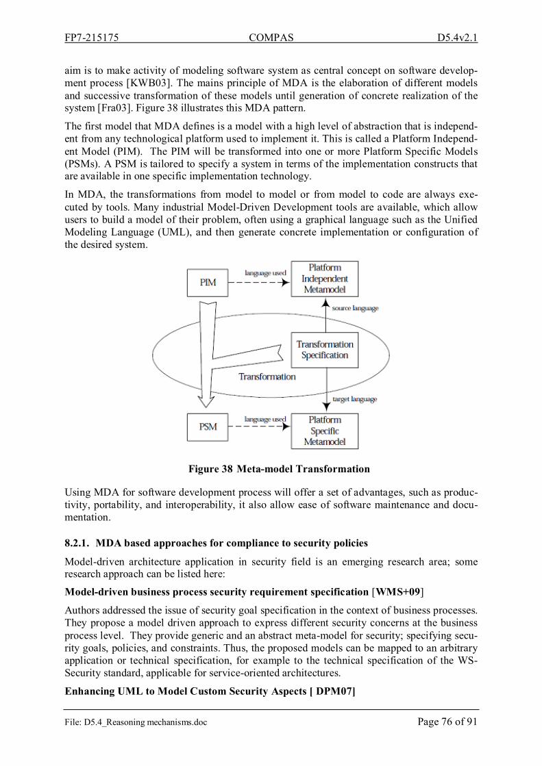
FP7-215175 COMPAS D5.4v2.1
File: D5.4_Reasoning mechanisms.doc Page 76 of 91
aim is to make activity of modeling software system as central concept on software develop-ment process [KWB03]. The mains principle of MDA is the elaboration of different models and successive transformation of these models until generation of concrete realization of the system [Fra03]. Figure 38 illustrates this MDA pattern.
The first model that MDA defines is a model with a high level of abstraction that is independ-ent from any technological platform used to implement it. This is called a Platform Independ-ent Model (PIM). The PIM will be transformed into one or more Platform Specific Models (PSMs). A PSM is tailored to specify a system in terms of the implementation constructs that are available in one specific implementation technology.
In MDA, the transformations from model to model or from model to code are always exe-cuted by tools. Many industrial Model-Driven Development tools are available, which allow users to build a model of their problem, often using a graphical language such as the Unified Modeling Language (UML), and then generate concrete implementation or configuration of the desired system.
Figure 38 Meta-model Transformation
Using MDA for software development process will offer a set of advantages, such as produc-tivity, portability, and interoperability, it also allow ease of software maintenance and docu-mentation.
8.2.1. MDA based approaches for compliance to security policies
Model-driven architecture application in security field is an emerging research area; some research approach can be listed here:
Model-driven business process security requirement specification [WMS+09]
Authors addressed the issue of security goal specification in the context of business processes. They propose a model driven approach to express different security concerns at the business process level. They provide generic and an abstract meta-model for security; specifying secu-rity goals, policies, and constraints. Thus, the proposed models can be mapped to an arbitrary application or technical specification, for example to the technical specification of the WS-Security standard, applicable for service-oriented architectures.
Enhancing UML to Model Custom Security Aspects [ DPM07]

FP7-215175 COMPAS D5.4v2.1
File: D5.4_Reasoning mechanisms.doc Page 77 of 91
Presented an approach to compose features from different security schemes, to represent cus-tom security aspects using specialized diagrams. This includes an expansion of UML to in-clude role-based, discretionary, and mandatory access controls, via new UML diagrams for roles, user authorizations, and delegation. As a result, designers are able to represent access control aspects with UML-based diagrams and an underlying scheme that combines Role Based Access Control (RBAC) [FSG+01], Mandatory Access Control (MAC) [LT02] and Discretionary Access Control (DAC) [BL75].
Applying Model Driven Architecture approach to Model Role Based Access Control System [Jin06]
Authors use the MDA approach with the UML profile to build the RBAC application and specification with graphic models and UML notations. The proposed approach focus on visu-ally modeling an RBAC system to fulfill the XACML profile, and automatic generation of the security infrastructure in XACML-format documents. This approach aim to enable software developers to become more productive and maintain high standards of software quality.
8.3. Meta-model and DSL for security DSLA DSL is a custom language that targets a small problem domain, which it describes and validates in terms native to the domain [CJK+07]. They have the potential to reduce complex-ity of software development by raising the abstraction level towards an application domain. So, applications are directly specified using domain concepts.
In contrast to a general-purpose programming language, such as C or Java, or general-purpose modeling language such as UMLD. Domain-specific modeling languages are customized to a particular application domain, and allow programming by specifying the solution directly using domain concepts.
Application domains are for instance: banking domain, insurance, military simulation, billing, and so on, each application domain is characterized by a bounded area of knowledge or con-cepts, e.g.
In practice, only one DSL may not be enough for describing an overall system, various DSL should be necessary, each DSL will focus on particular concern, and according to the applica-tion domain, different notations (textual, graphical, tabular) can be used.
Some benefits from using domain-specific modeling languages can be listed here, for more detail, see [D1.1]:
• A clear view of the problem domain is given.
• The solution is directly specified using domain concepts.
• Only valid relations between the domain concepts exist.
• Due to the separation between business and technical level, multiple levels of abstrac-tions exist.
• The productivity and the software quality can be improved because they are easier to maintain and the generated code does not contain bugs.
• The generated code can be tailored for the particular technology.
• Technical aspects are not shown to business experts.

FP7-215175 COMPAS D5.4v2.1
File: D5.4_Reasoning mechanisms.doc Page 78 of 91
Security is a very wide field characterized by complexity and diversity of used standards, lan-guages and technologies, so, using only one DSL to cover all the objectives of security will not be adequate, and will be even contrary with the spirit of the domain specific language, which have the main goal to bring closer the distance between languages, and development tools to the application domain. Considering that the knowledge and the concepts necessary to each under-field of security are narrow, and may require the intervention of different experts, different DSL is then necessary; each DSL will be dedicated to one under-field of security. In the following, we will present an Access Control DSL (ACD). This choice is not a hazard, because in addition to the fact that this last constitutes an active research field. It is strongly present in the specified security requirements of the ICT security scenario presented in [D6.1]. Our objective is not to develop algorithms or to solve any issues in the access control if-self, but quite simply to show the interest of using domain specific language like a new and an ef-fective means to model security requirements, and our contribution here should be seen with considering the model-driven architecture for Compliance proposed in COMPAS.
8.3.1. Access control DSL The objective of this DSL is to allow the specification of access control policies. As we evoked previously, this DSL should offer the ease of specification, and generation of access control policies code. Existing XML-based languages for specifying access control policies are very expressive, but policy definition is cumbersome. Thus, to make the specification of the access control policies more easily, we propose an abstract graphical DSL (domain specific language with graphical notation like UML). Thus, access control policies, which will be specified using the abstract graphic DSL, will be transformed to a low level language, such as XACML. But, it remains possible to define other transformations to others languages, like temporal logic for instance. For that, it is enough to develop the adequate modules of transformation.
XACML is an OASIS Standard, which aims to achieve the following objectives [Ver04]: • Create a portable and standard way of describing access control entities and their at-
tributes.
• Provide a mechanism that offers much finer granular access control than simply deny-ing or granting access.
The most important element of XACML model is a policy, which consists of: a set of rules, an identifier for rule-combining algorithms, a set of obligations, and a target. XACML policy model is shown in the following figure:

FP7-215175 COMPAS D5.4v2.1
File: D5.4_Reasoning mechanisms.doc Page 79 of 91
Figure 39 XACML policy model [Oas03]
Our ACD model (Figure 39) retakes the majority of XACML policy model elements. An ACD instance may define several policies, each policy may include several rules, a rule is permission or a prohibition (Deny), and it can be associated with several subject, actions, and resources.
A special type of permission is a SOD (Separation Of Duties) rule, which we will be pre-sented further.
A subject (see Figure 40) may be a user, a role, or AnySubject. A role can inherit from an-other role, thus a hierarchy of role can be defined (see Figure 45). A user may have one or several roles; AnySubject is a special subject which represents any subject of any type.
A policy can be associated with a security module, for example an XACML module, which means that this policy should be transformed to an XACML policy.
Each element is associated a graphical notation, which we will present further. To make the specification of policy graphically easier and clear, actions are graphically contained in the graphical element of a rule. The graphical elements of the rules, subjects and resources are contained in the graphical element of a policy.
The used graphical notation in a graphical DSL is an important element to make it use easier and closer to the application domain. In contrast to the graphical notation of the preceding modeling languages like UML for instance, which proposes a fixed standard notation, with DSL, we have total freedom to choose the notation which is more appropriate for our applica-tion domain or issue. This graphical notation can also evolve over the time.

FP7-215175 COMPAS D5.4v2.1
File: D5.4_Reasoning mechanisms.doc Page 80 of 91
Figure 40 Access control DSL model

FP7-215175 COMPAS D5.4v2.1
File: D5.4_Reasoning mechanisms.doc Page 81 of 91
Figure 41 Access control DSL model (Subject)
Figure 42 Access control DSL model (Rule)

FP7-215175 COMPAS D5.4v2.1
File: D5.4_Reasoning mechanisms.doc Page 82 of 91
The following schema gives a global view on our access control system working, starting from the instantiation of our ACD, to generation and execution of access control policy.
Figure 43 AAccess control system
Showed access control system (Figure 43) working can be summarized in the following steps:
− (1) Creation of an instance of the ACD.
− (2) Making reference to the process elements such (activity, services...), by extracting infor-mation from a process repository MORSE [HZD09].
− (3, 4) Specific templates parse ACD instance and generate access control policy (limited to XACML policy for the moment).
− (5) Deployment of XACML Policy in security policy repository.
− (6) When a requester (user or service) request the activation of an action on the process.
− (7) A special PEP component, which is a part of XACML framework, is responsible of creating an XACML request and sending it to the Policy Decision Point (PDP), which loads policies from security policy repository (8), then evaluates the request and sends back a re-sponse. The response can be either access permitted or denied, with the appropriate obliga-tions.

FP7-215175 COMPAS D5.4v2.1
File: D5.4_Reasoning mechanisms.doc Page 83 of 91
8.3.2. ACD Editor The ACD editor was created using Microsoft Csharp language and deployed as Microsoft visual studio plug-in. It comprises a main interface (1) for creating different access control policies, by instantiation of the ACD meta-model. This instantiation is done by drag and drop on this interface with graphical elements listed in tools window (2), this last one, contains three categories of elements:
• Abstract security elements: e.g. Policy, permission, subject, action, etc.
• Technical elements: more related with technical framework, which make reference to existing technical component, such as those responsible for code generation, e.g. XACML module, which transform the specified ACD graphical policy to an XACML policy. These kinds of elements can take place in the module panel (3) of the main in-terface.
• Application domain element: this last category, regroup those elements related to the application domain, such as Bank domain; these elements can be imported directly from the MORSE repository.
Figure 44 ACD editor
There is also another interface to create a hierarchy of roles. The following illustration (Figure 35) presents the hierarchical organization of the roles as well as the assignment of users and roles:
Figure 45 Role hierarchy definition

FP7-215175 COMPAS D5.4v2.1
File: D5.4_Reasoning mechanisms.doc Page 84 of 91
8.3.3. Access control specification In this section, we will present some access control rule, which take origin from the ICT Se-curity scenario, presented in [D6.1]. It is about four kinds of rules: simple access permis-sion/deny, and static/dynamic separation of duties, Reading ICT Security scenario is not in-dispensable to understand what follows,
8.3.3.i. Access permission and deny. A permission rule associate three types of elements: subjects, actions and resources, this asso-ciation mean that all subjects have the permission to activate all actions on all resources.
Figure 46 AccessAccess permission rule
And the same, a deny rule, mean that all subjects have not authorization to activated any ac-tion on the associated resources.
Figure 47 AAccess deny rule
When the rules of an access control policy are evaluated, they can produce different authori-zation, as it is the case when the two precedents rules are evaluated. The first one (Figure 46) will allow a CrditBroker subject to activate CustemerIdentification action on the BankProcess resource. But the second one (Figure 47) prohibited any Subject whatever it is to activate any action on any resource, so, there is an authorization ambiguity.
To resolve this issue, XACML define a Rule combining Algorithm property in a policy, which combine the effects of all the rules in a policy to arrive at a final authorization decision. This property can have the following values:
• Deny overrides: If any rule evaluates to Deny, then the final authorization decision is also Deny.
• Ordered deny overrides: Same as deny-overrides, except the order in which relevant rules are evaluated is the same as the order in which they are added in the policy.
• Permit overrides: If any rule evaluates to permit, then the final authorization decision is also Permit.
• Ordered permit overrides: Same as permit-overrides, except the order in which rele-vant rules are evaluated is the same as the order in which they are added in the policy.
• First applicable: The result of the first relevant rule encountered is the final authoriza-tion decision as well.
This property can be defined on the property window of a policy, see (4) Figure 44Figure 44.
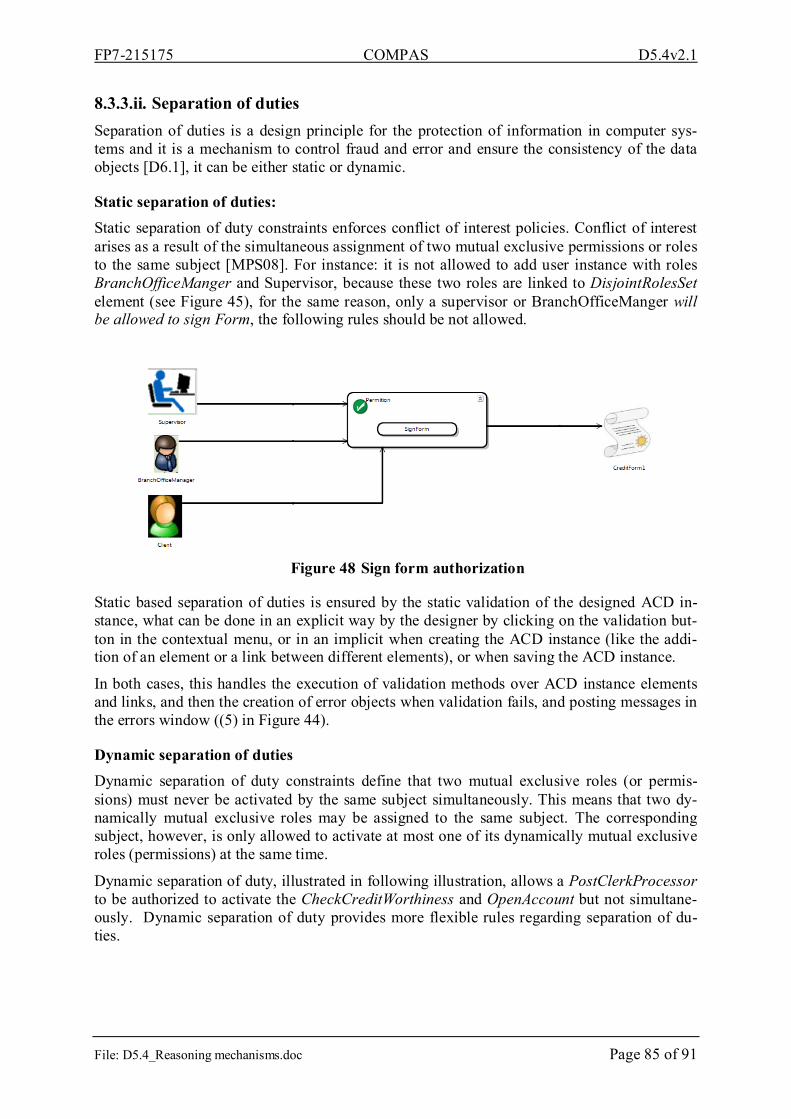
FP7-215175 COMPAS D5.4v2.1
File: D5.4_Reasoning mechanisms.doc Page 85 of 91
8.3.3.ii. Separation of duties Separation of duties is a design principle for the protection of information in computer sys-tems and it is a mechanism to control fraud and error and ensure the consistency of the data objects [D6.1], it can be either static or dynamic.
Static separation of duties: Static separation of duty constraints enforces conflict of interest policies. Conflict of interest arises as a result of the simultaneous assignment of two mutual exclusive permissions or roles to the same subject [MPS08]. For instance: it is not allowed to add user instance with roles BranchOfficeManger and Supervisor, because these two roles are linked to DisjointRolesSet element (see Figure 45), for the same reason, only a supervisor or BranchOfficeManger will be allowed to sign Form, the following rules should be not allowed.
Figure 48 Sign form authorization
Static based separation of duties is ensured by the static validation of the designed ACD in-stance, what can be done in an explicit way by the designer by clicking on the validation but-ton in the contextual menu, or in an implicit when creating the ACD instance (like the addi-tion of an element or a link between different elements), or when saving the ACD instance.
In both cases, this handles the execution of validation methods over ACD instance elements and links, and then the creation of error objects when validation fails, and posting messages in the errors window ((5) in Figure 44).
Dynamic separation of duties Dynamic separation of duty constraints define that two mutual exclusive roles (or permis-sions) must never be activated by the same subject simultaneously. This means that two dy-namically mutual exclusive roles may be assigned to the same subject. The corresponding subject, however, is only allowed to activate at most one of its dynamically mutual exclusive roles (permissions) at the same time.
Dynamic separation of duty, illustrated in following illustration, allows a PostClerkProcessor to be authorized to activate the CheckCreditWorthiness and OpenAccount but not simultane-ously. Dynamic separation of duty provides more flexible rules regarding separation of du-ties.

FP7-215175 COMPAS D5.4v2.1
File: D5.4_Reasoning mechanisms.doc Page 86 of 91
Figure 49 Dynamic separation of duties
8.3.3.iii. XACML policy generation Generation of XACML policy is done by specific templates, which parse the ACD instance, serialize them to XML format before transforming this last one to an XACML policy using XSLT (Xml Style Sheet Language Template) templates.
The following XACML policy fragment listing show an example of access control policy, which is the result of transforming the rule showed in Figure 49.
This XACML policy will be deployed into a security policy repository, and then evaluated when receiving a request for activation of CheckCreditWorthiness or OpenAccount on the BankProcess resource, the corresponding code should be contained with the Target element (Line 5), but, it is not showed here for saving place. Then, to allow the activation of the re-quested action, the specified rule condition (lines 6-25) should be evaluated to true. In this condition, we check that the requester subject has the role equal to PostClerck, which is done by the RoleBasedMatch function (nonstandard XACML functions). CheckSepartionOfDuties function (nonstandard XACML functions also) query a log file to check that the requester have not activated before an action among that listed in line 20.
1. <?xml version="1.0" encoding="utf-8"?>
2. <Policy xsi:schemaLocation="urn:oasis:names:tc:xacml:1.0:policy cs-xacml-schema-policy-01.xsd" PolicyId="Compas:ThalesACPolicy" RuleCombin-ingAlgId="urn:oasis:names:tc:xacml:1.0:rule-combining-algorithm:permit-overrides" xmlns="urn:oasis:names:tc:xacml:1.0:policy" xmlns:xsi="http://www.w3.org/2001/XMLSchema-instance">
3. <Description>Security DSL</Description>
4. <Rule RuleId="Compas:SeparationOfDuties" Effect="Permit" >
5. <Target> […]
6. <Condition FunctionId="urn:oasis:names:tc:xacml:1.0:function:and">
7. <Apply Func-tionId="http://research.sun.com/projects/xacml/names/function#RoleBasedMatch">
8. <AttributeValue DataType="http://www.w3.org/2001/XMLSchema#string">PostClerkProcessor</AttributeValue>
9. <Apply FunctionId="urn:oasis:names:tc:xacml:1.0:function:string-one-and-only">
10. <SubjectAttributeDesignator Attrib-uteId="urn:oasis:names:tc:xacml:1.0:subject:subject-id" DataType="http://www.w3.org/2001/XMLSchema#string" />
11. </Apply>
12. </Apply>

FP7-215175 COMPAS D5.4v2.1
File: D5.4_Reasoning mechanisms.doc Page 87 of 91
13. <Apply Func-tionId="http://research.sun.com/projects/xacml/names/function#CheckSepartionOfDuties">
14. <Apply FunctionId="urn:oasis:names:tc:xacml:1.0:function:string-one-and-only">
15. <SubjectAttributeDesignator DataType="http://www.w3.org/2001/XMLSchema#string" Attrib-uteId="urn:oasis:names:tc:xacml:1.0:subject:subject-id" />
16. </Apply>
17. <Apply FunctionId="urn:oasis:names:tc:xacml:1.0:function:string-one-and-only">
18. <ActionAttributeDesignator DataType="http://www.w3.org/2001/XMLSchema#string" Attrib-uteId="urn:oasis:names:tc:xacml:1.0:action:action-id" />
19. </Apply>
20. <AttributeValue DataType="http://www.w3.org/2001/XMLSchema#string">CheckCreditWorthiness,OpenAccount</AttributeValue>
21. <Apply FunctionId="urn:oasis:names:tc:xacml:1.0:function:string-one-and-only">
22. <ResourceAttributeDesignator DataType="http://www.w3.org/2001/XMLSchema#string" Attrib-uteId="urn:oasis:names:tc:xacml:1.0:resource:resource-id" />
23. </Apply>
24. </Apply>
25. </Condition>
26. </Rule>
27. </Policy>
Listing 10 XACML Policy Fragment for separation of duty
9. Reference documents
9.1. Internal documents [DoW] Annex 1 of the COMPAS Grant Agreement – Description of Work[D1.1]
Model-driven Integration Architecture for Compliance
[D2.2] “Initial Specification of Compliance Language Constructs and Operators”. Ver. 2.0 of 2009-06-08.
[D2.3] “Design of Compliance Language Run-time Environment and Architecture”.
Ver. 1.1 of 2009-07-31.
[D2.6] “Implementation of an integrated prototype handling interactive user specified-compliance requests in a compliance language”
[D4.1] “State-of-the-Art report on the existing approaches to improving reusability of processes and service compositions”. Ver. 2.0 of 2009-06-08.
[D4.2] “BPEL extensions for compliant services”. Ver. 1.0 of 2009-12-31.

FP7-215175 COMPAS D5.4v2.1
File: D5.4_Reasoning mechanisms.doc Page 88 of 91
[D4.3] “Classification and specification of reusable process artefacts”, to be published 2010-07-31.
[D4.4] “Supporting infrastructure – process engine, process artefact repository, proc-ess generation tool”. Ver. 1.0 of 2009-12-31.
[D5.3] “Final goal-oriented data model”. Ver. 1.0 of 2009-07-31.
[D5.5] “Business process performance dashboard”. Ver. 0.1 of 2009-11-13.
[D6.1] “Use Cases Definition, Metrics, and Validation Scenarios for Case Studies”. Ver. 1.0 of 2008-07-31.
[D7.1] Public Web-Site, http://www.compas-ict.eu.
9.2. External documents [AAA+07] A. Alves, A. Arkin, S. Askary, C. Barreto, and all. Web services business proc-
ess execution language version 2.0 (OASIS standard). WS-BPEL TC OASIS, http://docs.oasis-open.org/wsbpel/2.0/wsbpel-v2.0.html, 2007.
[Aal99] W.M.P. van der Aalst: Generic Workflow Models: How to Handle Dynamic Change and Capture Management Information? In: Proceedings of the Fourth IECIS International Conference on Cooperative Information Systems (COOPIS'99). IEEE Computer Society, 1999.
[AH05] W.M.P. van der Aalst and A.H.M. ter Hofstede: YAWL: Yet Another Work-flow Language. Information Systems, 30(4):245-275, 2005.
[Apa09a] Apache ActiveMQ, 2009. http://activemq.apache.org/
[Apa09b] Apache Orchestration Director Engine (Apache ODE), 2009. http://ode.apache.org.
[Att09] Attribute-Relation File Format (ARFF), 2009. http://www.cs.waikato.ac.nz/~ml/weka/arff.html.
[BAB+07] A. Buecker, P. Ashley, M. Borrett, M. Lu, S. Muppidi N. Readshaw.. I.B.M. Redbooks, Understanding SOA Security Design and Implementation: February 2007, Vervante, 2007.
[BBL07] G. Barash, C. Bartolini., W. Liya. Measuring and Improving the Performance of an IT Support Organization in Managing Service Incidents. 2nd IEEE/IFIP International Workshop on Business-Driven IT Management (BDIM07). pp. 11-18, 2007
[BCP+05] B. Benatallah, F. Casati, J. Ponge, F. Toumani. On temporal abstractions of web service protocols. In Orlando Belo, Johann Eder, João Falcão e Cunha, and Oscar Pastor, editors, CAiSE Short Paper Proceedings, volume 161 of CEUR Workshop Proceedings. CEUR-WS.org, 2005.
[BCT04] B. Benatallah, F. Casati, F. Toumani. Analysis and management of web service protocols. In Paolo Atzeni, Wesley W. Chu, Hongjun Lu, Shuigeng Zhou, and Tok Wang Ling, editors, ER, volume 3288 of Lecture Notes in Computer Sci-ence, pages 524–541. Springer, 2004.
[BL75] D. Bell, L. LaPadula.. Secure Computer Systems: Mathematical Foundations Model. Technical report, Mitre Corporation, 1975.
FP7-215175 COMPAS D5.4v2.1
File: D5.4_Reasoning mechanisms.doc Page 89 of 91
[BLS07] A. Bauer, M. Leucker, C. Schallhart. Runtime verification for LTL and TLTL, Technical Report TUM-I0724, TU München, 2007.
[BZ07] C. Baral, J. Zhoa. Non-monotonic Temporal Logics for Goal Specifications. Proc. 20th Int’l Intelligence Conference on Artificial Intelligence(IJCAI-07), pp. 236-242, India, 2007.
[CJK+07] S. Cook, G. Jones, S. Kent, et A. Wills.. Domain-Specific Development With Visual Studio DSLDSL Tools, Addison-Wesley Educational Publishers Inc, 2007.
[CLN03] J. Chomicki, J. Lobo, S. Naqvi.. Conflict Resolution Using Logic Program-ming, IEEE Transactions on Knowledge and Data Engineering, Vol. 15, No. 1, 2003.
[Cob05] Cobit 4.0 IT Governance Institute, 2005, http://www.isaca.org/Content/NavigationMenu/Members_and_Leaders/COBIT6/Obtain_COBIT/Obtain_COBIT.htm.
[Con02] Congress of the United States. Public Company AccountingReform and Inves-tor Protection Act (Sarbanes-Oxley Act), Pub. L. No. 107-204, 116 Stat. 745, 2002.
[CPK03] P. Chountas, I. Petrounias, V. Kodogiannis.. Temporal Modelling in Flexible Workflows, ISCIS, 2003.
[CMR+07] R. Chinnici, J-J. Moreau, A. Ryman, S. Weerawarana: Web Services Descrip-tion Language (WSDL) Version 2.0 Part 1: Core Language. W3C Recommen-dation, June 2007, http://www.w3.org/TR/wsdl20/.
[DAC98] M. Dwyer, G. Avrunin, J. Corbett.. Property Specification Patterns for Finite-State Verification, Proc. 2nd Int’l workshop on Formal Methods on Software Practice, pp. 7-15, USA, 1998.
[Det97] H. Dettmer. Goldratt’s Theory of Constraints: a systems approach to continu-ous improvement. ASQC Quality Press, pp 62-119, 1997.
[DPM07] S. Demurjian, J. Pavlich-Mariscal, L. Michel. . Enhancing UML to Model Cus-tom Security Aspects,, Proceedings of the 11th International Workshop. on Aspect-Oriented Modeling, co-located with MODELS 2007, Oct. 2007.
[Fra03] D.S. Frankel.. Model Driven Architecture: Applying MDA to Enterprise Com-puting, Wiley, 2003.
[FSG+01] D. Ferraiolo, R. Sandhu, S. Gavrila, R.Chandramouli.. Proposed NIST Stan-dard for Role-Based Access Control. ACM Transactions on Information and System Security 4, 2001.
[GCC+04] D. Grigori, F. Casati, M. Castellanos, U. Dayal, M. Sayal, M. Shan. Business Process Intelligence. Computers in Industry, 53(3), pp. 321–343, 2004.
[Gov05] G. Governatori, “Representing Business Contracts in RuleML”, International Journal of Cooperative Information Systems, 2005.
[GRR+08] C. Gunther, S. Rinderle-Ma, M. Reichert, W. Van Der Aalst, J. Recker. Using process mining to learn from process changes in evolutionary systems. Interna-tional Journal of Business Process Integration and Management. 3(1) p. 61-78, 2008.

FP7-215175 COMPAS D5.4v2.1
File: D5.4_Reasoning mechanisms.doc Page 90 of 91
[Har87] D. Harel, Statecharts: A Visual Formalism For Complex Systems, Science of Computer Programming 8 (1987) 231-274, North-Holland 1987.
[KC08] R. Kanneganti et P. Chodavarapu, SOA Security, Manning Publications, 2008.
[HK01] J. Han, M. Kamber. Data mining: concepts and techniques. San Francisco: Morgan Kaufmann, p. 550, 2001.
[Hol03] S. Holzner, Xpath Kick Start: Navigating Xml With Xpath 1.0 and 2.0, Sams Publishing, 2003.
[HZD09] Holmes, T.; Zdun, U.; Dustdar, S. MORSE: A Model-Aware Service Envi-ronment, 4th IEEE Asia-Pacific Services Computing Conference, 2009, IEEE Computer Society Press, IEEE Conference Proceeding
[Jin06] X. Jin.. Applying Model Driven Architecture approach to Model Role Based Access Control System, Master thesis, University of Ottawa, Ontario, Canada 2006.
[Jag99] H. Jagadish.. Managing Conflicts between Rules.., Journal of Computer and System Sciences, 1999.
[Mic09] Microsoft SQL Server 2008 – Business Intelligence, 2009. http://www.microsoft.com/sqlserver/2008/en/us/business-intelligence.aspx.
[NBZ06] N. Nagappan, T. Ball, A. Zeller. Mining metrics to predict component failures. Proceeding of the 28th International Conference on Software Engineering, pp. 452–461, 2006.
[KC04] R. Kimball, & J. Caserta. Data Warehouse ETL Toolkit. New York: John Willey& Sons, 2004.
[KC08] R. Kanneganti, P. Chodavarapu.. SOA Security, Manning Publications, 2008.
[KWB03] A. Kleppe, J. Warmer, W. Bast, MDA Explained: The Model Driven Architec-ture: Practice and Promise, Addison Wesley, 2003.
[LS09] M. Leucker et C. Schallhart. . A brief account of runtime verification,, Journal of Logic and Algebraic Programming, vol. 78, 2009, pp. 293-303.
[LSG09] R. Lu, S. Sadiq, G. Governatori. On Managing Business Processes Variants, Data & Knowledge Engineering Journal, Vol. 68, Issue 7, pp 642-664, 2009.
[LT02] M. Liebrand, T. Ting.. Role delegation for a distributed, unified RBAC/MAC. In: Proceedings of Sixteenth Annual IFIP WG 11.3 Working Conference on Data and Application Security, 2002.
[Mos06] H. Mosely.. Current Reality Trees: An Action Learning Tool for Root Cause Analysis, www.jhuccp.org/training/scope/starguide/toc/rootcauseanalysis.ppt, 2006.
[MPS08] J. Mendling, K. Ploesser, et M. Strembeck, “Specifying Separation of Duty Constraints in BPEL4People Processes,” Business Information Systems, 2008, pp. 273-284.
[Sql09] SQL Server Developer Center. 2009, http://msdn.microsoft.com/en-us/library/ms145506.aspx

FP7-215175 COMPAS D5.4v2.1
File: D5.4_Reasoning mechanisms.doc Page 91 of 91
[Oas03] OASIS, eXtensible Access Control Markup Language (XACML) Version 1.0, OASIS Standard, 18 February 2003, http://www.oasis-open.org/committees/xacml/repository/oasis-xacml-1.0.pdf.
[Oas05] OASIS: UDDI Version 3 Specification. OASIS Standard, 2005, http://www.oasis-open.org/committees/uddi-spec/doc/tcspecs.htm.
[Ora09] Oracle Business Intelligence Suite — Enterprise Edition Plus, 2009. http://www.oracle.com/appserver/business-intelligence/enterprise-edition.html.
[PMI04] PMI – Project Management Institute. A Guide to the Project Management Body of Knowledge (PMBOK® Guide) - Third Edition, Paperback, 2004.
[Pnu77] Amir Pnueli. The Temporal Logic of Programs. In Proceedings of the 18th Annual Symposium on Foundations of Computer Science (FOCS’77), Octo-ber-November 1977, pages 46–57. IEEE Comp. Soc. Press, October 1977.
[SEI09] SEI - Software Engineering Institute, Carnegie Mellon. Measurement and Analysis, 2009. http://www.sei.cmu.edu/measurement/tools/index.cfm
[SLM+10] D. Schumm, F. Leymann, Z. Ma, T. Scheibler, S. Strauch: Integrating Compli-ance into Business Processes: Process Fragments as Reusable Compliance Controls. In: Proceedings of the Multikonferenz Wirtschaftsinformatik (MKWI’10) (to appear), 2010.
[TSK06] P. Tan, M. Steinbach, V. Kumar. Introduction to data mining. Boston: Addison Wesley, p. 769, 2006.
[Ver04] M. Verma.. XML Security: Control information access with, 2004 XACML, http://www.ibm.com/developerworks/xml/library/x-xacml/
[Wek09] Weka - Waikato Environment for Knowledge Analysis. Weka 3: Data Mining Software in Java, 2009. http://www.cs.waikato.ac.nz/ml/weka/
[WF05] I. Witten & E. Frank. Data Mining Practical Machine Learning Tools and Techniques. 2nd Edition, 2005.
[WMS+09] C. Wolter, M. Menzel, A. Schaad, P. Miseldine, C. Meinel. . Model-driven business process security requirement specification,, Journal of Systems Archi-tecture, vol. 55, Avr. 2009, pp. 211-223.
[W3C1] W3C, http://www.w3.org/TR/xpath
[YMH+06] J. Yu, T. Manh, J. Han, Y. Jin. Pattern-Based Property Specification and Veri-fication for Service Composition, Web Information Systems – WISE, 2006.