D4200 ver 2.0 5.5 x 8.5.book(D4200 ver2.0 Cover 5.5 x...
88
User Guide D4200 TM LCD ARCHITECTURAL CONTROL STATION Software revision 2.0 and above
Transcript of D4200 ver 2.0 5.5 x 8.5.book(D4200 ver2.0 Cover 5.5 x...

User Guide
D4200TM LCD ARCHITECTURAL CONTROL STATIONSoftware revision 2.0 and above

NOTES:

User Guide
Leviton D4200 LCD Ver 2.0 Architectural Lighting Controller i
Table of Contents
WARNINGS............................................................... 1
INSTALLATION RECOMMENDATIONS................................ 2
INSTALLATIONPlan the System ................................................................. 3Power Requirements and Max Wire Lengths ......................... 6Terminating the Wire.......................................................... 7
Luma-Net III .................................................................7Luma-Net III Wire Recommendations .............................9Wiring the Phoenix Connector ......................................11Testing the Wiring .......................................................13
Configuring the Dimmer Cabinets .......................................14Install the Unit to the Wall .................................................14Power Up the Unit .............................................................17Checking the Version and Network ID .................................18
INITIAL SETUP AND PROGRAMMING .......................... 19Main Menu Flow Chart .......................................................20Programming and Configuration Level Flowchart................. 21Requirements for Setup .................................................... 18Navigating Menus..............................................................23Programming and Configuration Level Menu....................... 24
Accessing Programming and Configuration Level........... 24Setting the Network ID ............................................... 25More on Network IDs and Remote IDs ......................... 27Assigning Zones (Patching) ......................................... 28Misc. Settings Menu.....................................................29
Flags ....................................................................29Dimmer Readback ...........................................31Double Bump ..................................................32LCD Backlight ..................................................33Time Master ....................................................34Old Code Compatibility.....................................35IR Control .......................................................36Astronomical Clock Setup .................................36Max. Number of Zones Setup ...........................38
User Guide
Leviton D4200 LCD Ver 2.0 Architectural Lighting Controller ii
Personalities................................................................39Main Level Menus - Setup ..................................................41
Scheduling ..................................................................41Editing the Scheduler .............................................41Enabling the Scheduling .........................................43
Sequencer...................................................................43Editing the Sequencer ............................................44Enabling the Sequencer .........................................45
Zone Labels ................................................................45Zone Excludes .............................................................47Setting Date and Time .................................................48Editing Daylight Savings Time Region ...........................49Locks..........................................................................50
Setting the Record Lock Code.................................50Setting the Station Lock Code.................................51Enabling Record Lock.............................................51Enabling Station Lock.............................................52Overriding a Lock ..................................................53
OVERVIEW OF UNIT CONTROLS................................. 54Functions..........................................................................54Controls............................................................................54
OPERATION ............................................................ 57Controlling Light Levels ......................................................57
Minimum and Maximum Lighting Levels ........................57Individual Lighting Levels .............................................59
Checking Zone Names and Lighting Levels ..........................60Checking Scene Names ......................................................61Recording a Scene.............................................................61Snapshotting Light Levels from and Entry Station ................62Changing the MAX and OFF Lighting Levels .........................62Using the Optional Remote Control .....................................63Viewing Scheduled Events..................................................64Viewing the Sequencer ......................................................64
APPENDIX A - SETUP TABLES ................................... 66
APPENDIX B - LATITUDE AND LONGITUDE CHARTS ..... 70

User Guide
Leviton D4200 LCD Ver 2.0 Architectural Lighting Controller iii
APPENDIX C - MISCELLANEOUS INFORMATION ........... 79Clearing the Stations Memory.............................................79

User Guide
Leviton D4200 LCD Ver 2.0 Architectural Lighting Controller Page 1 of 80
Warnings
1: To be installed and/or used in accordance with appropriate electrical codes and regulations.
2: To be installed by a qualified Electrician.3: DO NOT CONNECT line voltage wires to low voltage terminals.4: For best lamp life, lamp manufacturers recommend their
fluorescent lamps should be operated at full brightness for a minimum or 100 hours before dimming is permitted. For best results, lamp brands and types should not be intermixed on a circuit
5: Disconnect power when servicing the dimmer, fixture or when changing lamps.
6: Indoor use only.7: TO AVOID FIRE, SHOCK OR DEATH: TURN OFF POWER AT
MAIN CIRCUIT BREAKER OR FUSE AND TEST THAT THE POWER IS OFF BEFORE WIRING!

User Guide
Leviton D4200 LCD Ver 2.0 Architectural Lighting Controller Page 2 of 80
Installation Recommendations
For best results using the Dimension 4200 Architectural Lighting Controller, follow these recommendations:
1: Plan the system before beginning the installation.2: Terminate the wiring3: Test the wiring.
Verify wiring for shorts and open circuits.4: Install all Stations5: Connect dimmer cabinets.6: Power up the Stations7: Program Each Station
Assign unique network ID numbers to stations.Connect one master station, and then one remote control station at a time.Verify that the first D4200 can properly control the dimmers assigned to it.Check the proper operation of each station as it is installed when multiple stations are involved.
If the lighting control fails or becomes sporadic, first check the wiring or network ID.
User Guide
Leviton D4200 LCD Ver 2.0 Architectural Lighting Controller Page 3 of 80
Installation
Plan the System:The system should be carefully planned out to take into consideration these important issues:
• Power Supply for Control Stations• Wire Size for Power Runs
On most systems, our applications engineering department has already managed these calculations for you so this information should be irrelevant. However, if this is not the case, like an ASAP (Quick Ship) program, when adding on to a system or planning for a remodel, you will want to take this information into consideration.
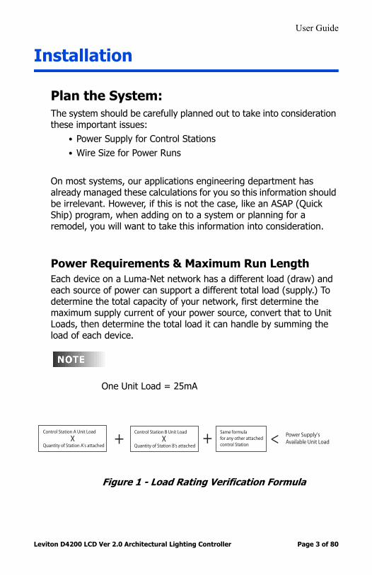
Power Requirements & Maximum Run LengthEach device on a Luma-Net network has a different load (draw) and each source of power can support a different total load (supply.) To determine the total capacity of your network, first determine the maximum supply current of your power source, convert that to Unit Loads, then determine the total load it can handle by summing the load of each device.
One Unit Load = 25mA
Figure 1 - Load Rating Verification Formula
Control Station A Unit Load
XQuantity of Station A's attached
+Same formulafor any other attached control Station
Control Station B Unit Load
XQuantity of Station B's attached
<+ Power Supply's Available Unit Load

User Guide
Leviton D4200 LCD Ver 2.0 Architectural Lighting Controller Page 4 of 80
Table 1 - Power Supply Maximum Unit Loads
Supply Maximum # of Unit Loads
a-2000D, 18 Channel,Standard Power Supply
49
a-2000D, 24 ChannelStandard Power Supply
47
a-2000D, 18 Channel,Large Power Supply
117
a-2000D, 24 ChannelLarge Power Supply
114
NPC – XP 49
NPC – DHV 0 (no Luma-Net)
NPC – DLR 49
i-Series e Dimmer Rack Consult Factory
Topaz/ENR Dimmer Rack Use DLR or NPC XP as Power Supply

User Guide
Leviton D4200 LCD Ver 2.0 Architectural Lighting Controller Page 5 of 80
Table 2 - Control Station Loads
Example:
Suppose we had a network with the following equipment:• D4200 LCD Stations• D4200 Entry Stations• Remote IR Station• Powered from an a-2000 24 Cabinet with a Standard Power
Supply
Use these quantities along with the Load Rating verification formula (Figure 1) to do the math and verify that the combined unit input load does not exceed the maximum input Unit Load Available.
Station Type Unit Load (per station)
Station Type Unit Load (per station)
D4200 LCD 5 D8000 Key switch 1
D4200 Entry (Button)
2 D8000 Port (LumaEdit, A/V, etc.)
2
D4200 Combine/Closure (Simple)
2 D8000 Combine/Closure (Advanced)
11
D4200 Remote I/R 2 Sapphire LCD 3
Luma-Net Hub 6 Sapphire Slider 2
D8000 LCD 3 Sapphire Button Stations
2
D8000 Entry (Button)
2
D8000 Slider 2
User Guide
Leviton D4200 LCD Ver 2.0 Architectural Lighting Controller Page 6 of 80
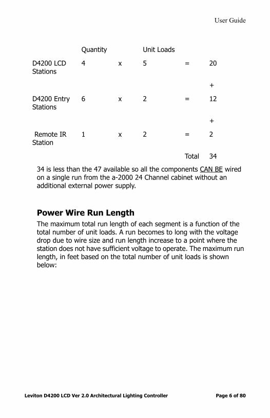
34 is less than the 47 available so all the components CAN BE wired on a single run from the a-2000 24 Channel cabinet without an additional external power supply.
Power Wire Run LengthThe maximum total run length of each segment is a function of the total number of unit loads. A run becomes to long with the voltage drop due to wire size and run length increase to a point where the station does not have sufficient voltage to operate. The maximum run length, in feet based on the total number of unit loads is shown below:
Quantity Unit Loads
D4200 LCD Stations
4 x 5 = 20
+
D4200 Entry Stations
6 x 2 = 12
+
Remote IR Station
1 x 2 = 2
Total 34

User Guide
Leviton D4200 LCD Ver 2.0 Architectural Lighting Controller Page 7 of 80
Table 3 - Wire Size vs. Length of Runs - Power Wiring
Terminating the Wiring
Luma-Net® IIIControl Stations can be located up to 2000 ft. from the dimming cabinet.
The 2000 ft. limitation is a RS485 digital communications specification. The power supply pair must be sized correctly for the control stations that are connected to them.
14 AWG (Feet) 12 AWG (Feet) 10 AWG Feet)
10 Unit Loads 1904 3000 4800
20 Unit Loads 952 1500 2400
30 Unit Loads 634 1000 1600
40 Unit Loads 476 750 1200
50 Unit Loads 380 600 960
60 Unit Loads 317 500 800
70 Unit Loads 272 428 685
80 Unit Loads 238 375 600
90 Unit Loads 211 333 533
100 Unit Loads 190 300 480
110 Unit Loads 173 272 436
120 Unit Loads 158 250 400

User Guide
Leviton D4200 LCD Ver 2.0 Architectural Lighting Controller Page 8 of 80
Luma-Net is wired Daisy Chained, station to station. For applications where runs become too long a Luma-Net Hub can be used. See Figure 2 for the correct ways to wire this system.
The cable should not pass near any source of electrical noise such as fluorescent circuits or motor wiring. Avoid close proximity to any AC wiring. All control/power iring must be in conduit.
Figure 2 - The Right and Wrong Way to Run Luma-Net
D4200 CONTROL STATION
PRESET SELECT STATION
C
12
18
1516
17
1314
6
910
11
78
34
5
12
AB
DMX CANCEL
LUMANET CLEAR
PHASE LOSS
AUXILIARY
FULL BRIGHT
COMMUNICATION PORTS
FAN
SAVE
FULL
SELECT
BRIGHT
a-2000D a-2000D
PRESET SELECT STATION
17
16
18
10
11
1413
15
12
5
87
9
6
B
2
43
C
1
A
D4200 CONTROL STATION
LUMANET
DMX
CLEAR
CANCEL
FAN
COMMUNICATION PORTS
FULL BRIGHT
AUXILIARY
PHASE LOSS
BRIGHT
SELECT
FULL
SAVE
LUMA-NET III HUB
Note: a-2000D Cabinet can be in the middle of a daisy chain
a-2000D
PRESET SELECT STATION
17
16
18
10
11
1413
15
12
5
87
9
6
B
2
43
C
1
A
D4200 CONTROL STATION
LUMANET
DMX
CLEAR
CANCEL
FAN
COMMUNICATION PORTS
FULL BRIGHT
AUXILIARY
PHASE LOSS
BRIGHT
SELECT
FULL
SAVE
The Right Way- No Hub! The Right Way- With a Hub!

User Guide
Leviton D4200 LCD Ver 2.0 Architectural Lighting Controller Page 9 of 80
Luma-Net Wire Recommendation:• See Table 4 for recommended Wire Types• Use RS485 compatible cable for the communications. It is
recommended that a cable with 2 Twisted Pair, 24 AWG, stranded conductors be used. The spare pair is for future uses.
• Capacitance of wire shall be 12pF/ft. or less• Nominal Impedance of wire shall be between 100-120 ohms• A second pair (#14 AWG stranded or larger) is required for the
power.• Drain/Shields to be tied together, insulated and grounded (on
one point only)!• We strongly recommend the use of either Belden 9829
or Belden 9729 for the Luma-Net wire runs.
The most effective way to insulate the drain/shield wire is to use a piece of heat shrink tubing!
.
Table 4- Luma-Net Recommended Wire
Manufacturer Catalog Number # of Pairs
Belden 9729, 9829 2
Belden 9841 1
Belden 88102 2 (Plenum Rated)
Alpha 6222C 1
Alpha 6412 1
User Guide
Leviton D4200 LCD Ver 2.0 Architectural Lighting Controller Page 10 of 80
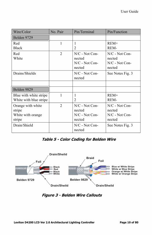
Table 5 - Color Coding for Belden Wire
Figure 3 - Belden Wire Callouts
Wire/Color No. Pair Pin/Terminal Pin/FunctionBelden 9729RedBlack
1 12
REM+REM-
RedWhite
2 N/C - Not Con-nectedN/C - Not Con-nected
N/C - Not Con-nectedN/C - Not Con-nected
Drains/Shields N/C - Not Con-nected
See Notes Fig. 3
Belden 9829Blue with white stripeWhite with blue stripe
1 12
REM+REM-
Orange with white stripeWhite with orange stripe
2 N/C - Not Con-nectedN/C - Not Con-nected
N/C - Not Con-nectedN/C - Not Con-nected
Drain/Shield N/C - Not Con-nected
See Notes Fig. 3
Drain/Sheild
Drain/Sheild
Belden 9729
Drain/Sheild
BraidFoil Foil
Belden 9829
BlackRedBlackWhite
Blue w/ White StripeWhite w/ Blue StripeOrange w/ White StripeWhite w/ Orange Stripe

User Guide
Leviton D4200 LCD Ver 2.0 Architectural Lighting Controller Page 11 of 80
If a remote DC power supply is used and you have multiple Luma-Net runs, all DC common wires must be joined at the power supply.
At the last control station or dimmer cabinet on both ends of the run, a small jumper wire must be run from the terminal labeled “Rem-” to the terminal marked “Term” on that last station. This jumper wire properly terminates the digital communications lines at the end of the line. See Figure 6.
Wiring the Phoenix ConnectorStep 1: Connect leads per wiring diagram as illustrated in Figure 4.Step 2: Twist strands of each lead tightly (making sure that there
are no stray strands) and push firmly into appropriate plug connector location.
Step 3: Tighten the screws on the plug connector—making sure that no bare conductor is showing.
Step 4: Tie the Drain/Shield wires together and insulate using a small piece of heat shrink tubing.
Step 5: Install termination jumpers as required. Remember a termination jumper is required at the two ends of the Luma-Net run.
User Guide
Leviton D4200 LCD Ver 2.0 Architectural Lighting Controller Page 12 of 80
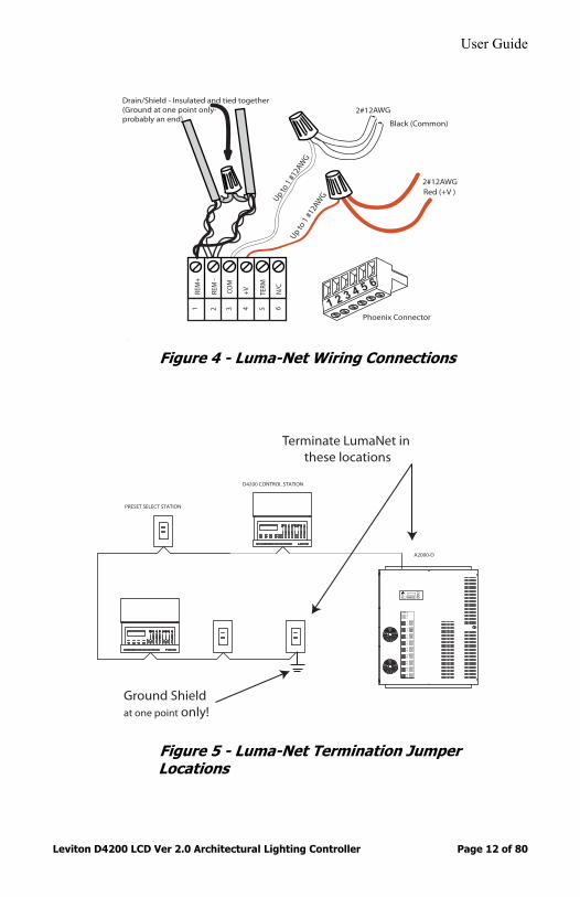
Figure 4 - Luma-Net Wiring Connections
Figure 5 - Luma-Net Termination Jumper Locations
REM
+
REM
-
COM
TERM
N/C
+V
1 2 3 4 5 6
Up to 1
#12
AWG
2#12AWG
2#12AWG
Up to 1
#12
AWG
Drain/Shield - Insulated and tied together (Ground at one point only-probably an end)
Red (+V )
Black (Common)
5 6
1 2 3 4
Phoenix Connector
D4200 CONTROL STATION
PRESET SELECT STATION
C
12
18
1516
17
1314
6
910
11
78
34
5
12
AB
DMX CANCEL
LUMANET CLEAR
PHASE LOSS
AUXILIARY
FULL BRIGHT
COMMUNICATION PORTS
FAN
SAVE
FULL
SELECT
BRIGHT
A2000-D
Ground Shieldat one point only!
Terminate LumaNet in these locations

User Guide
Leviton D4200 LCD Ver 2.0 Architectural Lighting Controller Page 13 of 80
Figure 6- Luma-Net Termination Jumper
The common (DCC) must be connected to earth ground at only one point in the run. The dimmer cabinet or a Luma-Net Hub (if used) are the most logical points.
Testing the WiringTo assure problem-free startup, it is important to check the system wiring for proper connections, shorts and opens.
The following procedure is recommended:Step 1: Test the following wire pairs for shorts at each station
location, using an ohmmeter or other continuity tester. 1-2 Open2-3 Open3-4 Open
Step 2: Repair any short circuits before continuing.
RE
M+
RE
M -
CO
M
TE
RM
N/C
+V
1 2 3 4 5 6
Termination Jumper
5 6
1 2 3 4
Phoenix Connector
User Guide
Leviton D4200 LCD Ver 2.0 Architectural Lighting Controller Page 14 of 80
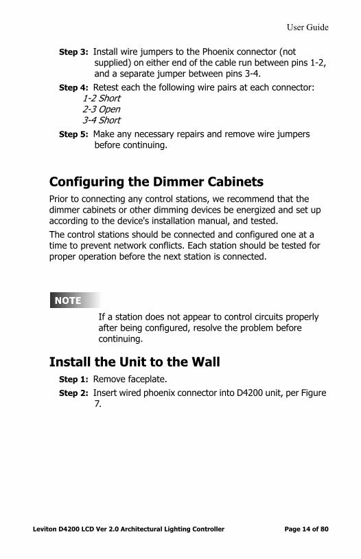
Step 3: Install wire jumpers to the Phoenix connector (not supplied) on either end of the cable run between pins 1-2, and a separate jumper between pins 3-4.
Step 4: Retest each the following wire pairs at each connector: 1-2 Short2-3 Open3-4 Short
Step 5: Make any necessary repairs and remove wire jumpers before continuing.
Configuring the Dimmer Cabinets Prior to connecting any control stations, we recommend that the dimmer cabinets or other dimming devices be energized and set up according to the device's installation manual, and tested. The control stations should be connected and configured one at a time to prevent network conflicts. Each station should be tested for proper operation before the next station is connected.
If a station does not appear to control circuits properly after being configured, resolve the problem before continuing.
Install the Unit to the WallStep 1: Remove faceplate.Step 2: Insert wired phoenix connector into D4200 unit, per Figure
7.

User Guide
Leviton D4200 LCD Ver 2.0 Architectural Lighting Controller Page 15 of 80
Figure 7 - Physical Wiring Illustration
Step 3: Mount Controller in 4-gang, gang box (107/16 in. wide, 21/2 in deep) with 4-gang device cover (1011/16 in. wide, 1/2
in. or 3/4 in. deep) as per Figure 8.
Control W ire
Phoenix Connector
User Guide
Leviton D4200 LCD Ver 2.0 Architectural Lighting Controller Page 16 of 80
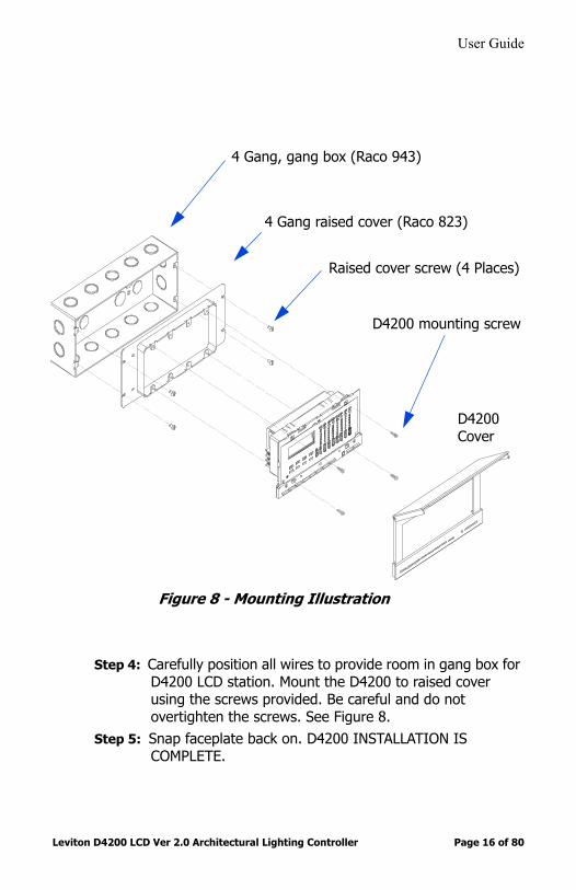
Figure 8 - Mounting Illustration
Step 4: Carefully position all wires to provide room in gang box for D4200 LCD station. Mount the D4200 to raised cover using the screws provided. Be careful and do not overtighten the screws. See Figure 8.
Step 5: Snap faceplate back on. D4200 INSTALLATION IS COMPLETE.
4 Gang, gang box (Raco 943)
4 Gang raised cover (Raco 823)
D4200 mounting screw
Raised cover screw (4 Places)
D4200Cover

User Guide
Leviton D4200 LCD Ver 2.0 Architectural Lighting Controller Page 17 of 80
Power Up the UnitThe default network ID is set to 000. When the station is reset or powered on and the network ID is zero, the LCD will prompt you for a valid network ID.
Upon initial power up you should see the following menu with the ID flashing:
You must enter a valid network ID to get to the main menu.
To set the master station ID number:Step 1: Press the Up and Down buttons to change the
value. See Figure 11 for the location of the buttons.Note: You need to set a unique number from 001 to 127 for it to function.
Step 2: Press the Select/Save button to save the values.
ID=000NET MASTER
MANUAL MODEM18 MON 12:00P
MAIN MENU

User Guide
Leviton D4200 LCD Ver 2.0 Architectural Lighting Controller Page 18 of 80
Checking the Version and Network IDTo display the version and ID information:
Step 1: Press the Menu/Cancel button.Step 2: Press the Up button once and the desired menu
appears on the LCD display.
The current version information and the Network ID are displayed in the following format:
Step 3: Press the Menu/Cancel or the Up and Down buttons to exit this menu.
Your version number should be the same or greater than this manual.
You are now ready to proceed with Initial Setup and Programming.
D4200 V 2.01 ID001BUILD:0209010815
Network IDSoftware version number
Date and time software was built

User Guide
Leviton D4200 LCD Ver 2.0 Architectural Lighting Controller Page 19 of 80
Initial Setup and Programming
The D4200 has two (2) menu Structures:• Main Menu Level• Programming and Configuration Level
The Main Menu Level is used for the following features:• View Schedule• Edit Schedule• Toggle Scheduler On or Off• View Sequencer• Edit Sequencer• Toggle the Sequencer On or Off• Edit Labels• Edit Excludes• Set Date/Time• Toggle Daylight Savings On or Off• Toggle the Record Lock Feature• Toggle the Station Lock Feature• Set the Station Lock Code• Set Record Lock Code
The Programming and Configuration Level Menus is used for the following features:
• Assign Zones• Edit Network
Network ID• Change Personalities• Miscellaneous Settings:
FlagsSetup Astronomical TimeSet the Maximum number of Zones

User Guide
Leviton D4200 LCD Ver 2.0 Architectural Lighting Controller Page 20 of 80
Figure 9 - LCD Screen Shots of Main Menu
MENU VIEW SCHEDULE
MENU EDIT SCHEDULE
E01:12:00A NONESMTWTFS
E01: 12:00 A NONE SMTWTFS
E64: 12:00A NONE - - - - - - - -
MENU SCHEDULER=OFF
MENU SCHEDULER= ON
SEQUENCER: E01: STOP
MENU VIEW SEQUENCER
MENUEDIT SEQUENCER
SEQUENCER: E01: STOP
SEQUENCER: E64: S01 01s
MANUAL MODE G1M18 MON 12:30P
MENUSEQUENCER= OFF
MENUSEQUENCER= ON
D4200 2.00 ID 001BUILD : 1023021151
E64: 12:00A NONESMTWTFS SEQUENCER:
E64: STOP
MENURECORD LOCK=ON
MENUSTATION LOCK=OFF
MENUEDIT LABELS
SELECT ZONE, ORSCENE TO EDIT
MENUEDIT EXCLUDES
EXCLUDE: SELECTA SCENE TO EDIT
MENUSET DATE/TIME
12:43P MON12H 10/28/2002
MENUDAYLIGHT SAVINGS
DAYLIGHT SAVINGSNORTH AMERICA
MENU RECORD LOCK=OFF
MENUSTATION LOCK=ON
MENU SET RECORD LOCK
SET RECORDLOCK CODE=000
SCENE 01M01 - - - - - - - - P01
MENU SET STATION LOCK
SET STATIONLOCK CODE=000
SCENE 01S01
ZONE 01Z01
User Guide
Leviton D4200 LCD Ver 2.0 Architectural Lighting Controller Page 21 of 80
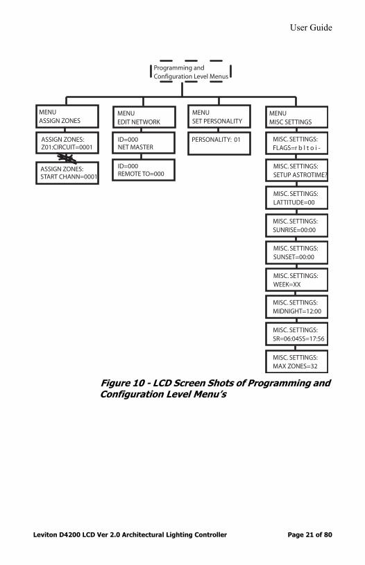
Figure 10 - LCD Screen Shots of Programming and Configuration Level Menu’s
Programming and Configuration Level Menus
MENUSET PERSONALITY
MENU EDIT NETWORK
MENUMISC SETTINGS
MENUASSIGN ZONES
ASSIGN ZONES:Z01:CIRCUIT=0001
ASSIGN ZONES:START CHANN=0001
ID=000NET MASTER
PERSONALITY: 01 MISC. SETTINGS:FLAGS=r b l t o i -
MISC. SETTINGS:SETUP ASTROTIME?
MISC. SETTINGS:LATTITUDE=00
MISC. SETTINGS:SUNRISE=00:00
MISC. SETTINGS:SUNSET=00:00
MISC. SETTINGS:WEEK=XX
MISC. SETTINGS:MIDNIGHT=12:00
MISC. SETTINGS:SR=06:04SS=17:56
MISC. SETTINGS:MAX ZONES=32
ID=000REMOTE TO=000
User Guide
Leviton D4200 LCD Ver 2.0 Architectural Lighting Controller Page 22 of 80
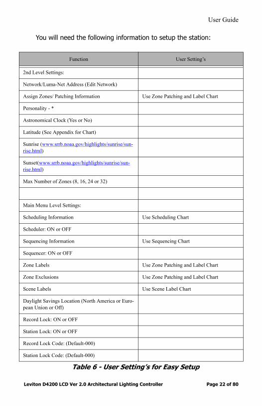
You will need the following information to setup the station:
Table 6 - User Setting’s for Easy Setup
Function User Setting’s
2nd Level Settings:
Network/Luma-Net Address (Edit Network)
Assign Zones/ Patching Information Use Zone Patching and Label Chart
Personality - *
Astronomical Clock (Yes or No)
Latitude (See Appendix for Chart)
Sunrise (www.srrb.noaa.gov/highlights/sunrise/sun-rise.html)
Sunset(www.srrb.noaa.gov/highlights/sunrise/sun-rise.html)
Max Number of Zones (8, 16, 24 or 32)
Main Menu Level Settings:
Scheduling Information Use Scheduling Chart
Scheduler: ON or OFF
Sequencing Information Use Sequencing Chart
Sequencer: ON or OFF
Zone Labels Use Zone Patching and Label Chart
Zone Exclusions Use Zone Patching and Label Chart
Scene Labels Use Scene Label Chart
Daylight Savings Location (North America or Euro-pean Union or Off)
Record Lock: ON or OFF
Station Lock: ON or OFF
Record Lock Code: (Default-000)
Station Lock Code: (Default-000)

User Guide
Leviton D4200 LCD Ver 2.0 Architectural Lighting Controller Page 23 of 80
Create a different sheet for each personality that you are going to use.
Navigating MenusTo navigate the menus, use the programming/navigation buttons:
Figure 11 - Programming Buttons
• Left and Right . Moves the cursor back and forth, or to the previous or next item.
• Up and Down . Scrolls through menus and submenus; changes selected values.
• Select/Save. Selects a value to be modified; saves the modified value.
• Menu/Cancel. Enters menu mode; exits submenus; exits menu mode.
• Clear. Clears or returns a selected value to zero.• Page Zones. Alternates the Zone numbers between 1-8 and
9-16, 17-24 and 25-32. The LCD will indicate which Page you are currently in. P1 refers to Zones 1-8, P2 indicates Zone 9-16, P3 indicates Zone 17-24 and P4 indicates to Zones 25-32 are active.
SelectSave
MenuCancel
Clear PageZones
Breakfast P1S01 TUE 04:29p LE
Page Number - P1 = Zones 1-8
Days of weekScene #
Indicates Schedule is active
P2 = Zones 9-16Scene Name
Indicates Station is Locked
P3 = Zones 17-24P4 = Zones 25-32

User Guide
Leviton D4200 LCD Ver 2.0 Architectural Lighting Controller Page 24 of 80
The Zone number LED’s do not light up on P3 or P4
Programming and Configuration Level Menu For the installation programming, you must use the Programming and Configuration Level menus along with the main level menus. These features include:
• Assigning Zones• Editing the Network• Setting Personality• Miscellaneous settings, including the • Flags: • Dimmer Readback, • Double Bump, • LCD Backlight Time Out• Time Master • Previous Code Compatibility and • IR Control.• Astronomical Time Clock Setup (sunrise, sunset, latitude) and• Maximum Number of Zones
To access the Programming and Configuration Level menu:Step 1: Press and hold the Menu/Cancel button for 10 seconds,
until LEVITON appears on the LCD display.Step 2: Immediately release the Menu/Cancel button.Step 3: Press and hold the Zone 4 Down button for at least 10
seconds, until LEVITON disappears from the LCD display.Step 4: Press the Menu button to access the Advanced features
that have been added to the menu.
When you are finished using the Setup menu selections, be sure to return to the regular menu.

User Guide
Leviton D4200 LCD Ver 2.0 Architectural Lighting Controller Page 25 of 80
To exit the Programming and Configuration Level menu:Step 1: Press and hold the Menu/Cancel button for 10 seconds,
until LEVITON appears on the LCD display.Step 2: Wait until the LCD display changes to MANUAL MODE.
Operate the buttons on the D4200 one at a time. Pressing two or more buttons at once may not yield the desired result.
Setting the Network ID - MANDATORYEach control station must have a unique ID number assigned to it. A Net ID of Zero (0) prevents the station from participating on the network.
These numbers may have been assigned at the factory prior to shipment. When assigned at the factory each station is labeled with its ID number.
The network ID must be set to a unique number between 001 and 127. If two stations have the same network ID, all stations may operate erratically and the dimmers will not respond to any station.
Default SettingsThe default network ID is set to 000. When the station is reset or powered on and the network ID is zero, the LCD will prompt you for a valid network ID.All eight personalities have their “Remote To” IDs set to 0. By default, when a “Remote To” IDs set to 0, it is as if it set to the same as the network ID.

User Guide
Leviton D4200 LCD Ver 2.0 Architectural Lighting Controller Page 26 of 80
Master stations and remote “Entry” stations used in the same room must be linked and their numbers bonded together so that the master station responds to the correct remote station. Once this is done, they must be installed in the same room or space. If the remote station is mounted in another room, it will still select preset Scenes in the master station that it is bonded to in the wrong room.
The master station and the remote stations mated to it must each have a different ID number. The remote station's target or remote to ID number must be mated to the master station's ID number to function properly in normal operation.
To set the master station ID number:
Step 1: Access the Programming and Configuration Level menuStep 2: Press the Menu/Cancel button.Step 3: Press the Up or Down buttons until EDIT
NETWORK? flashes on the LCD display.
Step 4: Press the Select/Save button to select the master station ID number.The Network ID number flashes.
Step 5: Press the Up and Down buttons to change the value.
You need to set a unique number from 001 to 127 for it to function.
MENUEDIT NETWORK
User Guide
Leviton D4200 LCD Ver 2.0 Architectural Lighting Controller Page 27 of 80
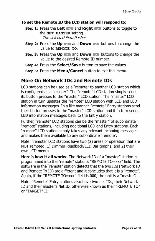
To set the Remote ID the LCD station will respond to:Step 1: Press the Left and Right buttons to toggle to
the NET MASTER setting.The selected item flashes.
Step 2: Press the Up and Down buttons to change the value to REMOTE TO.
Step 3: Press the Up and Down buttons to change the value to the desired Remote ID number.
Step 4: Press the Select/Save button to save the values. Step 5: Press the Menu/Cancel button to exit this menu.
More On Network IDs and Remote IDsLCD stations can be used as a “remote” to another LCD station which is configured as a “master”. The “remote” LCD station simply sends its button presses to the “master” LCD station. The “master” LCD station in turn updates the “remote” LCD station with LCD and LED information messages. In a like manner, “remote” Entry stations send their button presses to the “master” LCD station and it in turn sends LED information messages back to the Entry station.Further, “remote” LCD stations can be the “master” of subordinate “remote” stations, including additional LCD and Entry stations. Each “remote” LCD station simply takes any relevant incoming messages and makes them available to any subordinate “remote”.Note: “remote” LCD stations have two (2) areas of operation that are NOT remoted. 1) Dimmer Readback/LED Bar graphs, and 2) their own LCD menus.Here’s how it all works: The Network ID of a “master” station is programmed into the “remote” station’s “REMOTE TO=xxx” field. The software in the “remote” station detects that the two IDs (Network ID and Remote To ID) are different and it concludes that it is a “remote”. Again, if the “REMOTE TO=xxx” field is 000, the unit is a “master”. Note: “Remote” Entry stations also have two net IDs, their Network ID and their master’s Net ID, otherwise known as their “REMOTE TO” or “TARGET” ID.

User Guide
Leviton D4200 LCD Ver 2.0 Architectural Lighting Controller Page 28 of 80
Assigning Zones (Patching Zones to Dimmer Channels) - MANDATORYThe dimmer circuit channel number is assigned/patched to Luma-Net channels in the dimmer cabinet. A Zone can consist of a single dimmer, or several dimmers all driving a common area. For example, in a large church each chandelier might need one whole dimmer for power, but all chandeliers would be one Zone so the lights would all go up and down together. In the case of six chandeliers you would need six dimmers. The Zone assignment must be set to match the corresponding Luma-Net channel numbers in dimmer cabinets or control equipment.
Default SettingsThe factory default setting assigns Zone 1 to drive Luma-Net channel 1, Zone 2 to drive Dimmer 2, Zone 3 to drive Dimmer 3, etc. However, if input Zone 01 drives output dimmers 01, 02, and 03, input Zone 02 would need to be assigned to output dimmer 04.The default setting is generally satisfactory for most simple installations with one or two D4200 controls and one dimmer cabinet. Setting START CHANN to a number causes all zones to be assigned to sequential channel numbers starting with that same number and adding one to each zone there after. Setting START CHANN to NONE causes all zones to be assigned NONE. This is useful when only a few zones are to be used.
Unused zones should be set to NONE to disable LED level display for that zone. Also see the “Exclude Menu” in the operator’s manual.
Using the Patching table in Appendix A, assign a dimmer circuit channel number to each of the zones by:
Step 1: Press the Menu/Cancel button.Step 2: Press the Up or Down buttons until ASSIGN
ZONES? flashes on the display.Step 3: Press the Select/Save button.Step 4: Press the Up or Down buttons to scan through
the 8, 16, 24 or 32 ZONES and START CHANN.

User Guide
Leviton D4200 LCD Ver 2.0 Architectural Lighting Controller Page 29 of 80
Step 5: Press the Select/Save button to select ZONE or START CHANN.
The selected item flashes.Step 6: Press the Up and Down buttons to change the
value.Note: Press Clear to set the value to NONE.HELPFUL HINT: Press the Preset/Scenes 1 to 8 and Max/Off to generate the digits 1 to 8, 9 and 0 (zero).
Step 7: Press the Select/Save button to save the zone assignment.
Step 8: Repeat steps 4-7 for the remainder of the zones you wish to assign.
Step 9: Press Menu/Cancel to exit the menu.
MISC. SETTINGS MENUThis menu has three categories of sub-menus.
1: FLAGS.1.1 Dimmer Readback1.2 Double Bump1.3 LCD Display1.4 Time Master1.5 Old Code Compatibility1.6 IR Control
2: Set Up Astro Time.LatitudeSunriseSunsetDisplay of the current Week NumberDisplay of the calculated midnightDisplay of the current Sunrise and Sunset Time.
3: Maximum Zones.
1. FLAGS MenuThe following list of individually setable option flags. Use UPPER case to indicate the feature is ON, and use “lower” case to indicate the feature is OFF. By default these options are all OFF (lower case)

User Guide
Leviton D4200 LCD Ver 2.0 Architectural Lighting Controller Page 30 of 80
• Dimmer Readback: • Double Bump: This applies to the:• OFF Button- If turned “OFF” double bumping the button will
take it to it’s User setting while bypassing the set fade rate. If turned “ON”, it will bypass the fade rate while going to all Zones at zero output.
• MAX Button - If turned “OFF” double bumping this button this will take it to it’s User setting while bypassing the set fade rate. If turned “ON”, it will bypass the fade rate while going to all Zones at full output.
• LCD Backlight: When turned on the unit’s LCD Backlight will dim to a half bright level after a minute of no use.
• Time Master: If turned on, this will set the particular unit as the Time Master. Every so often during a day, this unit will broadcast a time setting that all other LCD stations on the network will synchronize to.
• Previous Code Compatibility: Allows the LCD station to work with Entry Stations that have 1.xx code. This is more of a concern if a LCD station is upgraded to new code, but the entry stations are not.
• IR Control: Allows the user to select if the IR port is active or disabled. On indicates that the IR port is active.
MISC. SETTINGS:FLAGS= r b L T o I
User Guide
Leviton D4200 LCD Ver 2.0 Architectural Lighting Controller Page 31 of 80
.
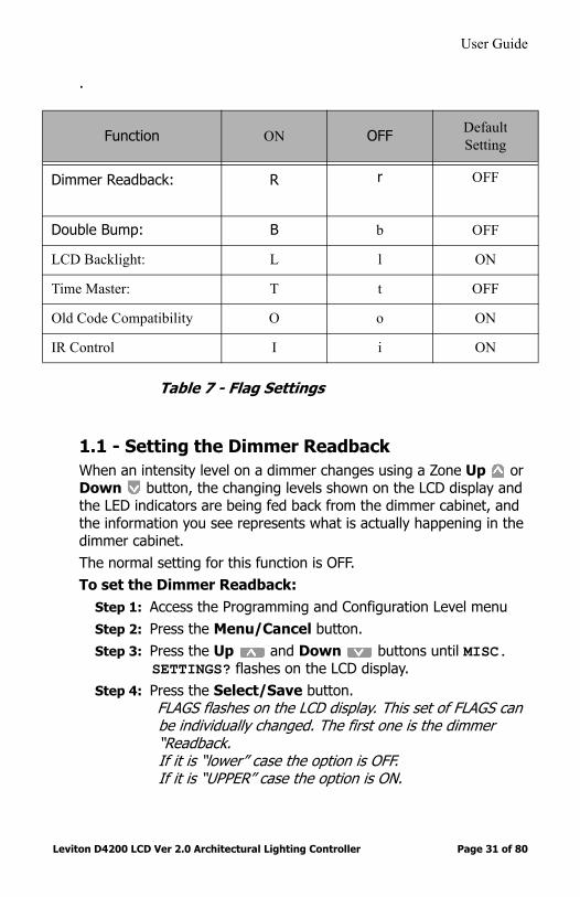
Table 7 - Flag Settings
1.1 - Setting the Dimmer ReadbackWhen an intensity level on a dimmer changes using a Zone Up or Down button, the changing levels shown on the LCD display and the LED indicators are being fed back from the dimmer cabinet, and the information you see represents what is actually happening in the dimmer cabinet.The normal setting for this function is OFF. To set the Dimmer Readback:
Step 1: Access the Programming and Configuration Level menu Step 2: Press the Menu/Cancel button.Step 3: Press the Up and Down buttons until MISC.
SETTINGS? flashes on the LCD display.Step 4: Press the Select/Save button.
FLAGS flashes on the LCD display. This set of FLAGS can be individually changed. The first one is the dimmer “Readback.If it is “lower” case the option is OFF.If it is “UPPER” case the option is ON.
Function ON OFF Default Setting
Dimmer Readback: R r OFF
Double Bump: B b OFF
LCD Backlight: L l ON
Time Master: T t OFF
Old Code Compatibility O o ON
IR Control I i ON

User Guide
Leviton D4200 LCD Ver 2.0 Architectural Lighting Controller Page 32 of 80
Step 5: Press the Select/Save button.The Dimmer Readback value flashes.
Step 6: Press the Up and Down buttons to change the value.“R” means the dimmer Readback is ON.“r” means the dimmer Readback is OFF.
Step 7: Press the Left and Right buttons to select the next Flagor proceed to the next step if you do not want to make any more changes to the remaining FLAGS.
Step 8: Press the Select/Save button to record the new setting.Step 9: Exit the Programming and Configuration Level menu.
1.2 - Setting the Double BumpAny time you select a SCENE, MAX, or OFF button, there is a fade time involved as the lights change to the new setting. If you tap a button twice, the lights immediately change to the new setting. However, only for the MAX and OFF buttons, if you have recorded a value other than full ON or full OFF, the Double Bump defeats this special setting, and the lights change to the true MAX or true OFF setting. When the Double Bump is set to OFF, the special settings for MAX and OFF are not defeated.To set the Double Bump:
Step 1: Access the Programming and Configuration Level menu Step 2: Press the Menu/Cancel button.Step 3: Press the Up and Down buttons until MISC.
SETTINGS? flashes on the LCD display.
Step 4: Press the Select/Save button.Step 5: FLAGS flashes on the LCD display.Step 6: Press the Select/Save button.
The Dimmer Readback value flashes.Step 7: Press the Right button to move to the next field.
The Double Bump value flashes.
MENUMISC. SETTINGS?
User Guide
Leviton D4200 LCD Ver 2.0 Architectural Lighting Controller Page 33 of 80
Step 8: Press the Up and Down buttons to change the value.“B” means the double bump is ON.“b” means the double bump is OFF.
Step 9: Press the Left and Right buttons to select the next Flagor proceed to the next step until you do not want to make any more changes to the remaining FLAGS.
Step 10: Press the Select/Save button to record the new setting.Step 11: Exit the Programming and Configuration Level menu.
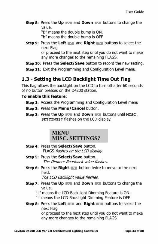
1.3 - Setting the LCD Backlight Time Out FlagThis flag allows the backlight on the LCD to turn off after 60 seconds of no button presses on the D4200 station.To enable this feature:
Step 1: Access the Programming and Configuration Level menuStep 2: Press the Menu/Cancel button.Step 3: Press the Up and Down buttons until MISC.
SETTINGS? flashes on the LCD display.
Step 4: Press the Select/Save button.FLAGS flashes on the LCD display.
Step 5: Press the Select/Save button.The Dimmer Readback value flashes.
Step 6: Press the Right button twice to move to the next field.The LCD Backlight value flashes.
Step 7: Press the Up and Down buttons to change the value.
“L” means the LCD BackLight Dimming Feature is ON.“l” means the LCD BackLight Dimming Feature is OFF.
Step 8: Press the Left and Right buttons to select the next Flagor proceed to the next step until you do not want to make any more changes to the remaining FLAGS.
MENUMISC. SETTINGS?

User Guide
Leviton D4200 LCD Ver 2.0 Architectural Lighting Controller Page 34 of 80
Step 9: Press the Select/Save button to record the new setting.Step 10: Exit the Programming and Configuration Level menu.
1.4 - Setting the Time Master FlagThis flag allows this D4200 station to take over as the Time Master. In this mode, a Time Master is the unit on the network that emits the time of day / date settings every 60 seconds. This helps all products that use the time / date information to stay synchronized.The automatic operating rules for this feature are as follows:
Step 1: Any unit which is active can be used to set the time and thus send the time broadcast to synchronize the clocks in all the other stations.
Step 2: If the station that has it’s clock set manually and has it’s Time Master Flag set, it becomes the Time Master and continues to automatically send the time every 60 seconds.
Step 3: If any station that is the current time master hears the time broadcast, it gives up being the time master.
Step 4: If any station that has it’s Time Master Flag set and it doesn’t hear the time broadcast for 120 seconds, it attempts to become the time master by sending out a time broadcast of it’s own internal clock data.
To enable this feature:Step 1: Access the Programming and Configuration Level menu.Step 2: Press the Menu/Cancel button.Step 3: Press the Up and Down buttons until MISC.
SETTINGS? flashes on the LCD display.Step 4: Press the Select/Save button.
FLAGS flashes on the LCD display.Step 5: Press the Select/Save button.
The Dimmer Readback value flashes.Step 6: Press the Right button three times to move to the
next field.The Time Master value flashes.
Step 7: Press the Up and Down buttons to change the value.
“T” means the Time Master is ON.“t” means the Time Master is OFF.

User Guide
Leviton D4200 LCD Ver 2.0 Architectural Lighting Controller Page 35 of 80
Step 8: Press the Left and Right buttons to select the next Flagor proceed to the next step until you do not want to make any more changes to the remaining FLAGS.
Step 9: Press the Select/Save button to record the new setting.Step 10: Exit the Programming and Configuration Level menu.
1.5 - Previous Code CompatibilityThis flag allows this D4200 station to work with units that have previous code installed on them. This usually occurs when a LCD station is upgraded to new code, but the entry stations are not. For installs where only the 2.xx code resides, you want to make sure that the flag is set to the “o”. To enable this feature:
Step 1: Access the Programming and Configuration Level menu.Step 2: Press the Menu/Cancel button.Step 3: Press the Up and Down buttons until MISC.
SETTINGS? flashes on the LCD display.Step 4: Press the Select/Save button.
FLAGS flashes on the LCD display.Step 5: Press the Select/Save button.
The Dimmer Readback value flashes.Step 6: Press the Right button four times to move to the
next field.The Previous Code Compatibility value flashes.
Step 7: Press the Up and Down buttons to change the value.“O” means the Previous Code Feature is ON (for use when units still have 1.xx code).“o” means the Previous Code Feature is OFF.
Step 8: Press the Left and Right buttons to select the next Flagor proceed to the next step if you do not want to make any more changes to the remaining FLAGS.
Step 9: Press the Select/Save button to record the new setting.Step 10: Exit the Programming and Configuration Level menu.
User Guide
Leviton D4200 LCD Ver 2.0 Architectural Lighting Controller Page 36 of 80
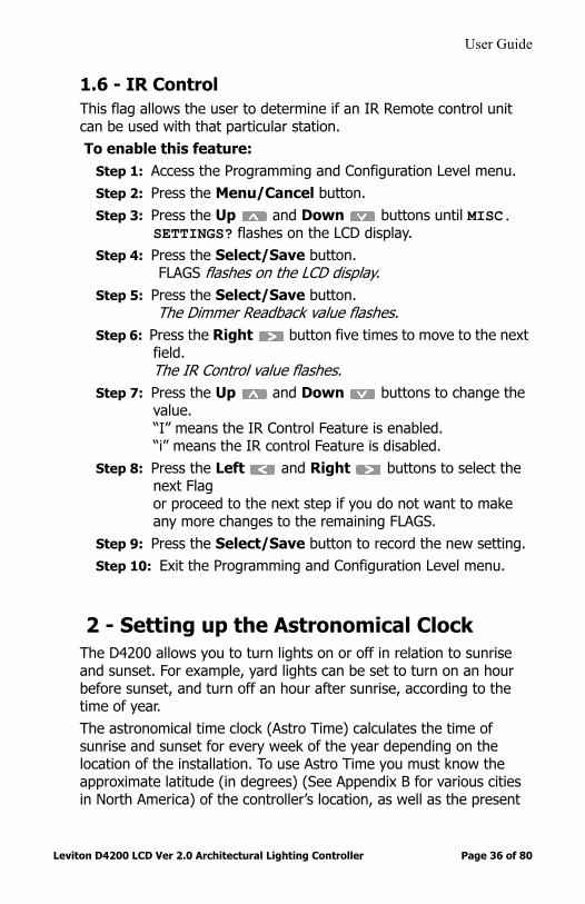
1.6 - IR ControlThis flag allows the user to determine if an IR Remote control unit can be used with that particular station. To enable this feature:
Step 1: Access the Programming and Configuration Level menu.Step 2: Press the Menu/Cancel button.Step 3: Press the Up and Down buttons until MISC.
SETTINGS? flashes on the LCD display.Step 4: Press the Select/Save button.
FLAGS flashes on the LCD display.Step 5: Press the Select/Save button.
The Dimmer Readback value flashes.Step 6: Press the Right button five times to move to the next
field.The IR Control value flashes.
Step 7: Press the Up and Down buttons to change the value.“I” means the IR Control Feature is enabled.“i” means the IR control Feature is disabled.
Step 8: Press the Left and Right buttons to select the next Flagor proceed to the next step if you do not want to make any more changes to the remaining FLAGS.
Step 9: Press the Select/Save button to record the new setting.Step 10: Exit the Programming and Configuration Level menu.
2 - Setting up the Astronomical ClockThe D4200 allows you to turn lights on or off in relation to sunrise and sunset. For example, yard lights can be set to turn on an hour before sunset, and turn off an hour after sunrise, according to the time of year. The astronomical time clock (Astro Time) calculates the time of sunrise and sunset for every week of the year depending on the location of the installation. To use Astro Time you must know the approximate latitude (in degrees) (See Appendix B for various cities in North America) of the controller’s location, as well as the present

User Guide
Leviton D4200 LCD Ver 2.0 Architectural Lighting Controller Page 37 of 80
time of sunrise and sunset (often found in the daily newspaper). Visit www.srrb.noaa.gov/highlights/sunrise/sunrise.html for a complete listing of Latitude, Longitude, Sunrise and Sunset information.
Step 1: Access the Programming and Configuration Level menu.Step 2: Press the Menu/Cancel button.Step 3: Press the Up or Down buttons until
MISC.SETTINGS? flashes on the display.Step 4: Use the Select/Save button to select the menu.
The current submenu flashes.
Step 5: Press the Up or Down buttons to scan through the submenus.
Step 6: Press the Select/Save button on SETUP ASTROTIME?
Step 7: Press the Up or Down buttons to set the LATTITUDE.
See Appendix for Latitude information for your locationStep 8: Press the Select/Save button to save the value.
The LCD display shows SUNRISE= with the hour field flashing.go to www.srrb.noaa.gov/highlights/sunrise/sunrise.htm for a complete listing of Sunrise and Sunset times for your location
Step 9: Press the Up and Down buttons to set the sunrise hour.
Step 10: Press the Right button to move to the minute field.The minute value flashes.
Step 11: Press the Up and Down buttons to set the minutes.
MISC. SETTINGS:FLAGS=rblto - - -
MISC. SETTINGS:SETUP ASTROTIME?
User Guide
Leviton D4200 LCD Ver 2.0 Architectural Lighting Controller Page 38 of 80
Step 12: Press the Select/Save button to save the value.The LCD display shows SUNSET= with the hour field flashing.go to www.srrb.noaa.gov/highlights/sunrise/sunrise.htm for a complete listing of Sunrise and Sunset times for your location
Step 13: Press the Up and Down buttons to set the sunset hour.
Step 14: Press the Right button to move to the minute field.The minute value flashes.
Step 15: Press the Up and Down buttons to set the minutes.
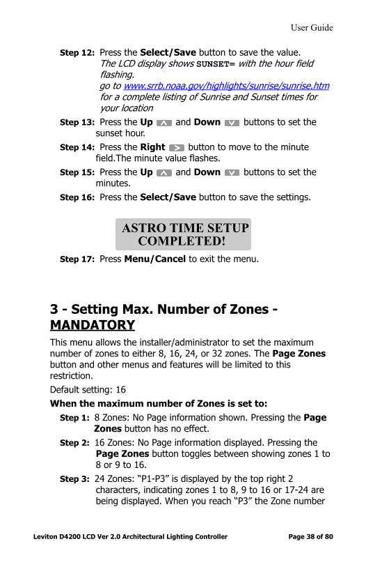
Step 16: Press the Select/Save button to save the settings.
Step 17: Press Menu/Cancel to exit the menu.
3 - Setting Max. Number of Zones - MANDATORYThis menu allows the installer/administrator to set the maximum number of zones to either 8, 16, 24, or 32 zones. The Page Zones button and other menus and features will be limited to this restriction.Default setting: 16When the maximum number of Zones is set to:
Step 1: 8 Zones: No Page information shown. Pressing the Page Zones button has no effect.
Step 2: 16 Zones: No Page information displayed. Pressing the Page Zones button toggles between showing zones 1 to 8 or 9 to 16.
Step 3: 24 Zones: “P1-P3” is displayed by the top right 2 characters, indicating zones 1 to 8, 9 to 16 or 17-24 are being displayed. When you reach “P3” the Zone number
ASTRO TIME SETUP COMPLETED!

User Guide
Leviton D4200 LCD Ver 2.0 Architectural Lighting Controller Page 39 of 80
indicators no longer are lit. Pressing of the Page Zones button toggles the pages.
Step 4: 24 Zones: “P1-P4” is displayed by the top right 2 characters, indicating zones 1 to 8, 9 to 16, 17-24 or 25-32 are being displayed. When you reach “P3 or P4” the Zone number indicators no longer are lit. Pressing of the Page Zones button toggles the pages.
To Set the Max Number of Zones:Step 1: Access the Programming and Configuration Level menu.Step 2: Press the Menu/Cancel button.Step 3: Press the Up or Down buttons until
MISC.SETTINGS? flashes on the display.Step 4: Use the Select/Save button to select the menu.
The current submenu flashes.
Step 5: Press the Up or Down buttons to scan through the submenus.
Step 6: Press the Select/Save button on MAX ZONES=XX? Step 7: Press the Up or Down buttons to set the scroll
throughout the options.Step 8: Press the Select/Save button to save the settings.Step 9: Press Menu/Cancel to exit the menu.
PersonalitiesYou can set up various personalities that include different preset Scenes. For example, a church could use one set of eight preset Scenes for Sunday church service, and a different set of eight preset Scenes for evening choir performances. By choosing Personality 02, the second (choir performance) set of Scenes could be recorded without disturbing the normal Sunday church service settings.
The following information will need to be re-entered for each personality:
MISC. SETTINGS:FLAGS=rblto - - -

User Guide
Leviton D4200 LCD Ver 2.0 Architectural Lighting Controller Page 40 of 80
• Scenes (including fade rates)• Scene Labels• Remote To ID numbers (unless already at zero (0))• Assign Zones• Exclusions• Zones• Zone Labels
To set the personality:Step 1: Access the Programming and Configuration Level menu.Step 2: Press the Menu/Cancel button.Step 3: Press the Up and Down buttons until SET
PERSONALITY? flashes on the LCD display.
Step 4: Press the Select/Save button.The current Personality number flashes.
Step 5: Press the Up and Down buttons to change the value.
Step 6: Press the Select/Save button to save the value.Step 7: SET PERSONALITY? flashes again.Step 8: Press Menu/Cancel to exit the menu.
Testing the StationsTest each station by raising and lowering each zone that is assigned to a dimmer. Check to see that control of the dimmer cabinet or other control device is correct and smooth.
Main Level Menus
MENUSET PERSONALITY?

User Guide
Leviton D4200 LCD Ver 2.0 Architectural Lighting Controller Page 41 of 80
SchedulingThe D4200 is already programmed to accept up to 64 possible Events, numbered E01 through E64. The default values are 12:00a (12:00 am), NONE (no Scene), and SMTWTFS (all days of the week).To create Events you must edit the schedule and change the default values (see Editing the Schedule).
The types of events that may be scheduled are:• Scenes 1 to 16, MAX or OFF• Sequencer ON / OFF / RESUME, or GOTO <step> (1 to 64)• Photo CELL ON
Editing the ScheduleTo simplify the process, use the Scheduling table in Appendix A.To edit the schedule:
Step 1: Press the Menu/Cancel button.Step 2: Press the Up and Down buttons until EDIT
SCHEDULE? flashes on the LCD display.Step 3: Press the Select/Save button.
The current Event number flashes.Scheduled Events are displayed in the following format:
Step 4: Press the Up and Down buttons to scan through the possible Events.
Step 5: Press the Select/Save button to select the Event you want to edit.The HOUR field flashes.
Step 6: Press the Up and Down buttons to change the HOUR value.Note: Press Clear to return the value to 12.
E01: 07:12a S01 SMTWTFS
Scenenumber
Scheduledtime
Eventnumber
Days of week

User Guide
Leviton D4200 LCD Ver 2.0 Architectural Lighting Controller Page 42 of 80
Step 7: Press the Right button to move to the next field. Step 8: The MINUTES field flashes.Step 9: Press the Up and Down buttons to change the
value.Note: Press Clear to return the value to 00.
Step 10: Press the Right button to move to the next field. The Scene field flashes. Note “NONE” appears as default.
Step 11: Press the Up and Down buttons to select a Scene or one of the following choices:
• None• Seq. Step - Starts a Sequence at a particular step• Cell ON - Turns the Photocell option on at the a-2000D dimmer
rack• Resume - Resumes the Sequencer• Seq OFF - Turns the Sequencer Off• Seq ON - Turns the Sequencer Om• OFF - Applies the OFF button• MAX - Applies the MAX button• Scene - Applies a Scene
Note: Press Clear to return the value to NONE. Erasing a Scene effectively erases the Event.
Step 12: Press the Right button to move to the next field. The first value in the SMTWTFS (Days of week) field flashes.
Step 13: Press the Up and Down buttons to change the value. When a dash replaces a day of the week, it becomes inactive. Note: Press Clear to change the values to - - - - - - - (inactive).
Step 14: Press the Right button to move to the next field. and use the Up and Down buttons to change the value. Repeat this process for all 7 days.
Step 15: Press the Select/Save button to save these values for the Event.The Event number flashes again.

User Guide
Leviton D4200 LCD Ver 2.0 Architectural Lighting Controller Page 43 of 80
Step 16: Press the Up and Down buttons to select another Event and repeat steps 5 -15 until all Events have been programmed.
Step 17: Press the Menu/Cancel button if you are finished editing events.You return to the VIEW SCHEDULE? menu command.
The LCD display times out and returns to MANUAL MODE if no changes are made for 60 seconds.
Enabling the SchedulerTo enable or disable the scheduler:
Step 1: Press the Menu/Cancel button.Step 2: Press the Up and Down buttons until
SCHEDULER= flashes on the LCD display.Step 3: Press the Select/Save button.
The current status of the scheduler flashes.Step 4: Press the Up and Down buttons to change the
value.Step 5: Press the Select/Save button to save the value.Step 6: Press the Menu/Cancel button to exit this menu.
SequencerThe sequencer causes Scenes to be activated in a timed sequence. The sequence may be programmed to run once or continuously in a loop. The sequence can be activated manually (preset/scene buttons) or by the event timer (scheduler). The sequence can be sub-divided into groups of events simply by the use of commands that start it (GOTO a specific step). There is a table provided in Appendix A to help you set up the sequencer schedule.

User Guide
Leviton D4200 LCD Ver 2.0 Architectural Lighting Controller Page 44 of 80
Editing the SequencerTo simplify the process, use the Sequencer table in Appendix A.To edit the sequencer:
Step 1: Press the Menu/Cancel button.Step 2: Press the Up and Down buttons until EDIT
SEQUENCER? flashes on the LCD display.Step 3: Press the Select/Save button.
The Event number flashes. The sequence Events are displayed in the following format:
• STOP indicates the end of the sequence and the sequencer is disabled after a STOP Event is executed.
• LOOP indicates the sequencer will immediately restart the sequence and will run continuously.
• Events after a START or LOOP command are not executed.Step 4: Press the Up and Down buttons to scan
through the possible Events.Step 5: Press the Select/Save button to select an Event. Step 6: Press the Up and Down buttons to change the
value.Note: Press Clear to change the value to SKIP.
• STOP• LOOP• GOTO _ _• SKIP• Scene (With Delay Time)• MAX• OFF
SEQUENCER:E01: STOP 01s
Eventnumber
Scene orcommand
Time untilnext step

User Guide
Leviton D4200 LCD Ver 2.0 Architectural Lighting Controller Page 45 of 80
Step 7: For the following types, Scene, Max and OFF, you must also set a delay time. Press the Left and Right buttons to highlight a Delay time.
Step 8: Press the Up and Down buttons to change the value.
Step 9: Press Select/Save to save the value.Step 10: Repeat Steps 4-9 for each Sequence you wish to
program.Step 11: Press the Menu/Cancel button to exit this menu.
The “SKIP” control command is a way to insert a “place holder” or “no operation” when you want to temporarily exclude some other scene or control command... then put it back at a later time.
Enabling the SequencerThis function globally enables or disables the sequencer.To enable or disable the sequencer:
Step 1: Press the Menu/Cancel button.Step 2: Press the Up and Down buttons until
SEQUENCER= flashes on the LCD display.Step 3: Press the Select/Save button.
The OFF or ON value flashes.Step 4: Press the Up and Down buttons to change the
value.Note: Press Clear to change the value to OFF.
Step 5: Press the Select/Save button to save the value.Step 6: Press the Menu/Cancel button to exit this menu.
Zone Labels: Naming a Scene or ZoneYou can program alphanumeric labels with up to 14 characters for any Scene MAX, OFF or Zone ID buttons. To name a Scene or a Zone:

User Guide
Leviton D4200 LCD Ver 2.0 Architectural Lighting Controller Page 46 of 80
Step 1: Press the Menu/Cancel button.Step 2: Press the Up and Down buttons until EDIT
LABELS? flashes on the LCD display.Step 3: Press the Select/Save button.Step 4: Press the SCENE, MAX, OFF, Zone ID or Up or
Down button you want to edit.Step 5: Press the Left and Right buttons to select a
character to edit,or proceed to the next step if you want to change the current character.
Step 6: Press the Up and Down buttons to scan through the alphanumeric values.
Press Clear to clear the entire value. See the Graphic below for a shortcut to Alpha Keys
.
Figure 12 - Shortcut for Alpha Keys
Step 7: Press the Select/Save button to save the value and edit the label.
1 9 2 10 3 11 4 12 5 13 6 14 15 16
MasterMaster
7 8A B C D E F G H
I J K L M N O P Q
R S T U V W X Y ZPagePageZonesZones
Space

User Guide
Leviton D4200 LCD Ver 2.0 Architectural Lighting Controller Page 47 of 80
Step 8: Select another Zone or Scene to edit,or press the Menu/Cancel button twice to exit this menu.
Editing Zone ExcludesThis menu allows the installer to edit which zones are not to be included in recorded preset/scenes. This menu is “record” locked. To Exclude a zone from a Scene:
Step 1: Press the Menu/Cancel button.Step 2: Press the Up and Down buttons until EDIT
EXCLUDES? flashes on the LCD display.Step 3: Press the Select/Save button. The LCD changes to:
Step 4: Choose a preset scene from preset/scene buttons, remote presets; IR or Entry Station. The LCD changes to (assuming you pressed the preset scene 1):
Step 5: Press the Zone Up to exclude a zone and the Zone Down button to include a zone. When you press a Zone Up button, the corresponding“-” changes to a digit which represents the least significant digit of the affected zone’s ID (Example: Zone 16 is represented by 6, 25 is represented by a 5). Alternately, when you press a Zone Down button the “digit” returns to a dash (“-”) meaning the zone is included.
6: Use Page Zones button to select up to 4 pages of zones. Page 1 is zones 1 to 8, page 2 is zones 9 to 16, page 3 is zones 17 to 24, page 4 is zones 25 to 32.
Use Clear to clear all “excludes” i.e. to include all zones. By default all zones are included.
EXCLUDE: SELECTA SCENE TO EDIT
SCENE 01M01 - - - - - - - - P01

User Guide
Leviton D4200 LCD Ver 2.0 Architectural Lighting Controller Page 48 of 80
When operating the unit, the Master Up and Down buttons uses the last preset/scene’s zone exclude list as defined in this section.
Setting the Date and Time - MANDATORYThe date and time are important for the scheduler to operate properly. The date must be set correctly if Astronomical Time Events are used.To set the date and time:
Step 1: Press the Menu/Cancel button.Step 2: Press the Up and Down buttons until SET
DATE/TIME? flashes on the LCD display.Step 3: Press the Select/Save button.
The HOUR field flashes. The date and time are displayed in the following format:
Step 4: Press the Left and Right buttons to select a field to edit,or proceed to the next step until you want to change the current field.
Step 5: Press the Up and Down buttons to change the value.
Step 6: Press the Select/Save button to save a value. Step 7: Press the Menu/Cancel button to exit this menu.
Setting the date and time will set date and time on all other stations on the same lighting control network (using the Luma-Net™ data protocol).
03:04P TUE 12H 01/25/2001
Day of weekTime
Format (12/24) Date (M/D/Y)

User Guide
Leviton D4200 LCD Ver 2.0 Architectural Lighting Controller Page 49 of 80
Setting the date and time causes the unit to become the “Time Master” if the option to enable this feature is configured in the Misc. Settings Menu.
The internal time is kept in “standard” time.... when the Daylight Saving feature in enabled and it is “in Daylight Saving”, the displayed time is shown in Daylight Saving Mode with the “a” of “am” or the “p” of “pm” shown in UPPER case (“A” or “P”) if in 12 Hour Mode. If in 24 Hour mode, a lower case “d” is appended to the time to confirm daylight saving mode. Standard time is indicated by displaying a “s”.
Editing The Daylight Saving Time RegionThis new menu allows the installer to edit which region of the world to use for the Daylight Saving feature. The choices are:
• OFF• North America (Adds 1 hour to displayed time from 1st Sunday in
April to Last Sunday in October at 2:00am).
• European Union (Adds 1 hour to displayed time from Last Sunday of March at 1:00am until Last Sunday of October at 1:00am
Step 1: Press the Menu/Cancel button.Step 2: Press the Up and Down buttons until
DAYLIGHT SAVING? flashes on the LCD display.Step 3: Press the Select/Save button.
The DAYLIGHT SAVING field flashes. Step 4: Press the Select/Save button again. Step 5: Press the Up and Down buttons until your
choice is flashing.Step 6: Press the Select/Save button to record the change.

User Guide
Leviton D4200 LCD Ver 2.0 Architectural Lighting Controller Page 50 of 80
LOCKSThe D4200 has two types of Locks:
• Record Lock - Record Lock prevents any data stored in the station's memory from being altered. You must enter the Record Lock code when recording Scenes and editing any data.
• Station Lock - Station Lock restricts access to the controller. You must enter the Station Lock Code when recording Scenes and editing any data. Setting the Station Lock also sets the Record Lock. When you turn the Station Lock OFF, The Record Lock stays ON.
Setting the Record Lock CodeThe Record Lock code must be a number between 000 and 999. The default code is 000.
Shortcut: Use a code number between 000 and 999, as the Preset - Scene buttons 1 to 8 and MAX (9) and OFF (0) can be used to enter the code in directly.
Figure 13 - Shortcut Buttons
To set the Record Lock code:Step 1: Press the Menu/Cancel button.Step 2: Press the Up and Down buttons until SET
RECORD LOCK? flashes on the LCD display.Step 3: Press the Select/Save button.
The CODE field flashes
2 4 5 6 7 81 3 9 0
MAX. OFF
Off Button
Max ButtonScene Button

User Guide
Leviton D4200 LCD Ver 2.0 Architectural Lighting Controller Page 51 of 80
Step 4: Press the Up and Down buttons to change the value.
Note: Press Clear to reset the value to 000.Step 5: Press the Select/Save button to save the value.
SET RECORD LOCK? flashes again. Step 6: Press the Menu/Cancel button to exit this menu.
Setting the Station Lock CodeThe Station Lock Code must be a number between 000 and 999. The default code is 000.
Shortcut: Use a code number between 000 and 999, as the Preset - Scene buttons 1 to 8 and MAX (9) and OFF (0) can be used to enter the code in directly.
To set the station lock code:Step 1: Press the Menu/Cancel button.Step 2: Press the Up and Down buttons until SET
STATION LOCK flashes on the LCD display.Step 3: Press the Select/Save button.
The CODE Field flashesStep 4: Press the Up and Down buttons to change the
value. Press Clear to reset the value to 000.
Step 5: Press the Select/Save button to save the value.Step 6: SET STATION LOCK? flashes again. Step 7: Press the Menu/Cancel button to exit this menu.
Enabling the Record Lock
Be sure to set the Record Lock code before enabling the Record Lock.
User Guide
Leviton D4200 LCD Ver 2.0 Architectural Lighting Controller Page 52 of 80
To enable or disable the Record Lock:Step 1: Press the Menu/Cancel button.Step 2: Press the Up and Down buttons until RECORD
LOCK= flashes on the LCD display.Step 3: Press the Select/Save button.
The current value flashes.Step 4: Press the Up and Down buttons to change the
value.Press Clear to change the value to OFF.
Step 5: Press the Select/Save button to save the value. RECORD LOCK= flashes again.
Step 6: Press the Menu/Cancel button to exit this menu.
Enabling the Station Lock
Be sure to set the Station Lock Code before enabling the Station Lock.
To enable or disable the Station Lock:Step 1: Press the Menu/Cancel button.Step 2: Press the Up and Down buttons until STATION
LOCK= flashes on the LCD display.Step 3: Press the Select/Save button.
The current value flashes.Step 4: Press the Up and Down buttons to change the
value.Press Clear to change the value to OFF.
Step 5: Press the Select/Save button to save the value. STATION LOCK= flashes again.
Step 6: Press the Menu/Cancel button to exit this menu.
User Guide
Leviton D4200 LCD Ver 2.0 Architectural Lighting Controller Page 53 of 80
Overriding a LockIf the control station is locked by a code number, the LCD displays ENTER CODE when a locked operation is attempted. To override a lock:
1: Press the Up and Down buttons to enter the programmed code number (000-999).
Press Clear to begin entering numbering from zero (0).
Shortcut: Use a code number between 000 and 999, as the Preset - Scene buttons 1 to 8 and MAX (9) and OFF (0) can be used to enter the code in directly.
Note:
Step 2: Press the Select/Save button to enter the value.The originally selected operation begins and the unit remains unlocked for approximately 5 minutes.
The PIN 6 key lock input on the Luma-Net connector always locks the station overriding the station lock and there is no “Pass Code” to override this lock.
Congratulations:Your D4200 LCD Station is completely set up and ready for use.
User Guide
Leviton D4200 LCD Ver 2.0 Architectural Lighting Controller Page 54 of 80
Overview of Unit Controls
FunctionsWith the Dimension 4200 Control Station, you can program up to sixteen different Scenes. Each Scene controls lighting levels for up to 32 lighting channels, or Zones. Once you adjust the lighting levels for the Zones you are using and record these light levels as one of the sixteen Scenes, you can name the Scenes and schedule Events activating those Scenes. For example, for a restaurant setting you could record and name Scenes for “BREAKFAST, LUNCH and DINNER.”You can lock the control station to prevent modifications (see LOCKS) or to prevent all operation (see Enabling the Station Lock). The unit can be locked by a code number, or by a key switch or other remote device.If you lock the unit by key switch or remote device, the locked operation will not function until the key switch or remote lock is released.
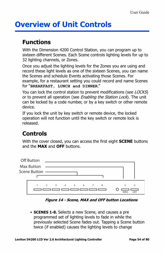
ControlsWith the cover closed, you can access the first eight SCENE buttons and the MAX and OFF buttons.
Figure 14 - Scene, MAX and OFF button Locations
• SCENES 1-8. Selects a new Scene, and causes a pre programmed set of lighting levels to fade in while the previously selected Scene fades out. Tapping a Scene button twice (if enabled) causes the lighting levels to change
2 4 5 6 7 81 3 9 0
MAX. OFF
Off Button
Max ButtonScene Button

User Guide
Leviton D4200 LCD Ver 2.0 Architectural Lighting Controller Page 55 of 80
immediately, bypassing the fade time. When Scenes are named, the name appears on the LCD display when the button is pressed, for example, “BREAKFAST, LUNCH, or DINNER.”
• MAX. Brings all assigned lighting levels gradually to the maximum level. Tapping the button twice brings all assigned lighting levels immediately to the maximum level, bypassing the fade time. This button can be programmed for custom lighting levels, for example, reducing the maximum light level to conserve energy, or providing longer lamp life.
• OFF. Brings all lighting levels gradually to the minimum level (the default value is no light). Tapping the button twice brings all assigned lighting levels immediately to the minimum level, bypassing the fade time. This button can be programmed for custom lighting levels, for example, keeping a minimum light level for safety reasons.
With the cover open, you can also access the LCD display, the Master Up and Down buttons, the individual Zone Up and Down buttons, the Zone identification and status buttons, the Zone level indicators, and the programming/navigation buttons.
Figure 15 - D4200 Buttons
1 9 2 10 3 11 4 12 5 13 6 14 15 16
MasterMaster
PagePageZonesZonesClearClear
MenuMenuCancelCancel
SelectSelectSaveSave
2-Line, 16-Character LCD
IR Receiver
Scene Programming or
Recall
MasterDim/Bright
All Off
ZoneDim/Bright
7 8
ZoneInformation Display
All Zones to Maximum Brightness
Change Zone
Clear
Select Option and Save
Menu and Cancel Button
Previous Field orChange Scene Blank
Shortcut
Previous/NextMenu Option
Next Field orChange Scene BankShortcut
User Guide
Leviton D4200 LCD Ver 2.0 Architectural Lighting Controller Page 56 of 80
Operate the buttons on the D4200 one at a time.
If you activate the station lock code or the station lockout switch, the Master Up/Down, Zone Up/Down, SCENE, MAX, and OFF buttons are disabled until a code is entered or the lockout switch is deactivated (see Overriding a Lock).
User Guide
Leviton D4200 LCD Ver 2.0 Architectural Lighting Controller Page 57 of 80
Operation
Controlling Lighting LevelsYou can control the lighting levels in two ways. You can change all the lights at once, or change individual lighting levels without changing the programmed settings.
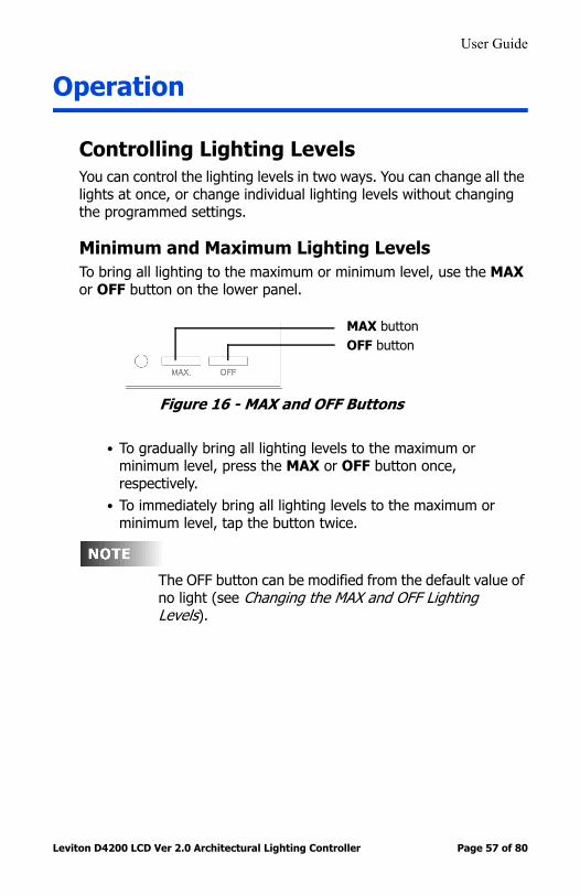
Minimum and Maximum Lighting LevelsTo bring all lighting to the maximum or minimum level, use the MAX or OFF button on the lower panel.
Figure 16 - MAX and OFF Buttons
• To gradually bring all lighting levels to the maximum or minimum level, press the MAX or OFF button once, respectively.
• To immediately bring all lighting levels to the maximum or minimum level, tap the button twice.
The OFF button can be modified from the default value of no light (see Changing the MAX and OFF Lighting Levels).
MAX buttonOFF button

User Guide
Leviton D4200 LCD Ver 2.0 Architectural Lighting Controller Page 58 of 80
The approximate lighting level for each Zone is represented by the Zone level LED indicators.
Figure 17 - Zone Level Indicators
Overall Lighting LevelsTo adjust overall lighting levels, open the cover and use the Master Up and Down buttons. Once you have recorded Scenes, use these buttons to modify all the Zones concurrently.
• To increase or decrease all assigned lighting Zones by one percent, momentarily press the Master Up or Down button.
• To rapidly increase or decrease the lighting levels, press and hold the button.
The approximate lighting levels for each Zone are represented by the Zone level indicators. The lighted Scene button goes dark and the LCD display shows MANUAL MODE after the Master Up or Down button is pressed. You can record these new values for the Scene if you prefer the new lighting levels.
Since levels in all assigned Zones increase or decrease by the same amount, lighting levels eventually become the same in all Zones when you press the Master Up or Down buttons. As each Zone reaches its maximum or minimum level, it stays at that level while the other Zones catch up.
Master Up and Down buttons
Zone LevelLED Indicato
User Guide
Leviton D4200 LCD Ver 2.0 Architectural Lighting Controller Page 59 of 80
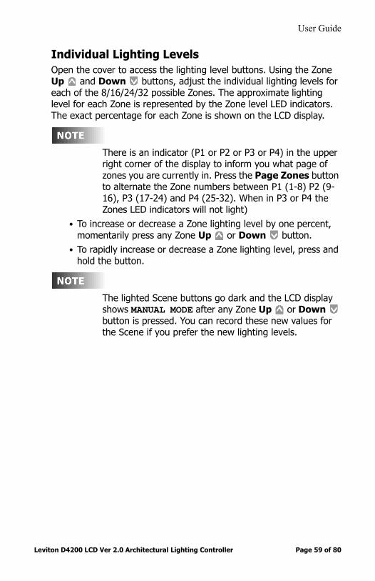
Individual Lighting LevelsOpen the cover to access the lighting level buttons. Using the Zone Up and Down buttons, adjust the individual lighting levels for each of the 8/16/24/32 possible Zones. The approximate lighting level for each Zone is represented by the Zone level LED indicators. The exact percentage for each Zone is shown on the LCD display.
There is an indicator (P1 or P2 or P3 or P4) in the upper right corner of the display to inform you what page of zones you are currently in. Press the Page Zones button to alternate the Zone numbers between P1 (1-8) P2 (9-16), P3 (17-24) and P4 (25-32). When in P3 or P4 the Zones LED indicators will not light)
• To increase or decrease a Zone lighting level by one percent, momentarily press any Zone Up or Down button.
• To rapidly increase or decrease a Zone lighting level, press and hold the button.
The lighted Scene buttons go dark and the LCD display shows MANUAL MODE after any Zone Up or Down button is pressed. You can record these new values for the Scene if you prefer the new lighting levels.

User Guide
Leviton D4200 LCD Ver 2.0 Architectural Lighting Controller Page 60 of 80
Checking Zone Names and Lighting LevelsThe Zone Status buttons are located above the Zone LED level indicators.
Figure 18 - Zone Status ButtonsTo check a Zone:
Step 1: Press a Zone status button.The LCD display shows the Zone number or name (if you have programmed one); the precise lighting level is displayed as a percentage. Current lighting levels are not affected.
The LCD display returns to normal after a few seconds.
Just to the right of the “Zxx:” symbol on the 2nd line is a field that is normally blank. If this Zone is excluded from the current scene, a minus sign (“-”) appears in this position.
Zone LED Indicator
Zone Status Buttons
ZONE:08Z08: LEVEL= 26%

User Guide
Leviton D4200 LCD Ver 2.0 Architectural Lighting Controller Page 61 of 80
Checking Scene NamesYou can check for a Scene name without initiating the Scene.To Check the Scene Name:
Step 1: Press the CLEAR ButtonStep 2: Immediately Press the SCENE button you are interested
in.Step 3: To View another Scene name, Repeat from Step 1.
Recording a SceneAfter adjusting individual lighting levels, you can record lighting levels to a Scene.
Step 1: With the cover open, press and hold the Scene button you want to record until the LCD display shows FADETIME.The flashing number indicates the fade time in seconds.
Step 2: Press the Up and Down buttons beneath the LCD display to adjust the fade time.
Step 3: Press the Right button to select the REC TO SCENE option.
Step 4: Press the Up and Down buttons beneath the LCD display to pick the Scene you wish to record.
Step 5: Press the Select/Save button to record the lighting levels and fade time.
The LCD display shows RECORDING SCENE TO S00, with S00 representing the Scene you chose.
User Guide
Leviton D4200 LCD Ver 2.0 Architectural Lighting Controller Page 62 of 80
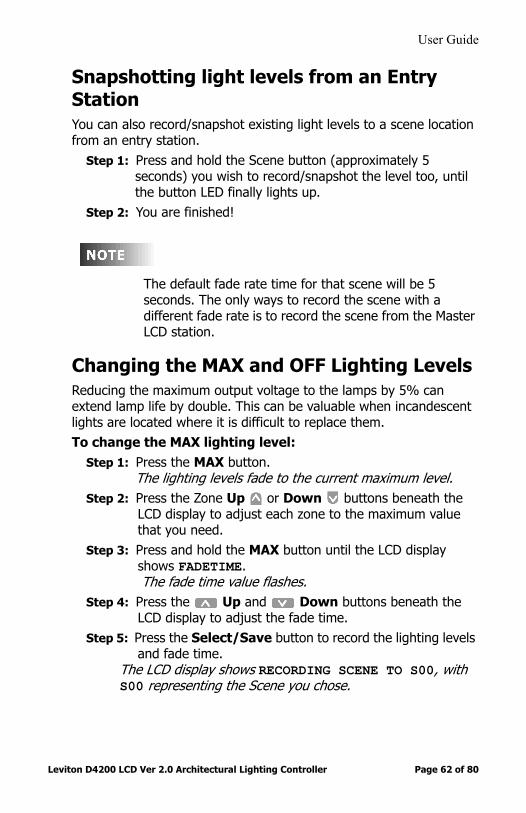
Snapshotting light levels from an Entry StationYou can also record/snapshot existing light levels to a scene location from an entry station.
Step 1: Press and hold the Scene button (approximately 5 seconds) you wish to record/snapshot the level too, until the button LED finally lights up.
Step 2: You are finished!
The default fade rate time for that scene will be 5 seconds. The only ways to record the scene with a different fade rate is to record the scene from the Master LCD station.
Changing the MAX and OFF Lighting LevelsReducing the maximum output voltage to the lamps by 5% can extend lamp life by double. This can be valuable when incandescent lights are located where it is difficult to replace them.To change the MAX lighting level:
Step 1: Press the MAX button.The lighting levels fade to the current maximum level.
Step 2: Press the Zone Up or Down buttons beneath the LCD display to adjust each zone to the maximum value that you need.
Step 3: Press and hold the MAX button until the LCD display shows FADETIME.The fade time value flashes.
Step 4: Press the Up and Down buttons beneath the LCD display to adjust the fade time.
Step 5: Press the Select/Save button to record the lighting levels and fade time.
The LCD display shows RECORDING SCENE TO S00, with S00 representing the Scene you chose.

User Guide
Leviton D4200 LCD Ver 2.0 Architectural Lighting Controller Page 63 of 80
For safety reasons, you might want to prevent certain lights from turning completely off. Modifying the OFF lighting level changes the minimum lighting levels.To change the OFF lighting level:
Step 1: Press the OFF button.The lighting levels fade to the current minimum level.
Step 2: Press the Zone Up or Down buttons to adjust each zone to the minimum value that you need.
Step 3: Press and hold the OFF button until the LCD display shows FADETIME.
The fade time value flashes.Step 4: Press the Up and Down buttons beneath the
LCD display to adjust the fade time. Step 5: Press the Select/Save button to record the lighting levels
and fade time.The LCD display shows RECORDING SCENE TO S00, with S00 representing the Scene you chose.
When the Double Bump feature is on, tapping the MAX or OFF buttons twice overrides any high and low limits. Therefore, if MAX and OFF are set at any levels other than full bright and full off, the Double Bump feature should be turned off.
Using the Optional Remote ControlIf you have purchased the optional remote control, you can use it to operate the Master RAISE/ LOWER, SCENE, MAX and OFF buttons in the same manner as indicated above. The maximum range for the remote control is approximately 30 feet.

User Guide
Leviton D4200 LCD Ver 2.0 Architectural Lighting Controller Page 64 of 80
If you activate the station lock code or the station lockout switch, the remote control will override the locks and be able to recall preset Scenes; even though, the station is locked.
Viewing Scheduled EventsTo view currently scheduled Events:
Step 1: Press the Menu/Cancel button.Step 2: Press the Up and Down buttons until VIEW
SCHEDULE? flashes on the LCD display.Step 3: Press the Select/Save button.
Scheduled Events are displayed in the following format:
A dash replaces the day of the week when the schedule is disabled on that day. Sunrise and sunset for astronomical time are displayed as SR +- (offset time) or SS +- (offset time). Offset time is displayed in 15-minute increments. You must enter the latitude of your location to use astronomical time, which controls the lighting according to season, adjusting the lights in relation to sunrise and sunset. Astronomical time is displayed when Time is scrolled past midnight.
Step 4: Press the Menu/Cancel button when you are finished.You return to the VIEW SCHEDULE? menu command.
Viewing the SequenceThe sequencer causes Scenes to be activated in a timed sequence. The sequence may be programmed to run once or continuously in a loop. The sequence can be activated manually (preset/scene buttons)
E01: 12:00a S01 SMTWTFS
Scene toactivate
Scheduledtime
Eventnumber
Days of week

User Guide
Leviton D4200 LCD Ver 2.0 Architectural Lighting Controller Page 65 of 80
or by the event timer (scheduler). The sequence can be sub-divided into groups of events simply by the use of commands that start it (GOTO a specific step).To view the sequencer:
Step 1: Press the Menu/Cancel button.Step 2: Press the Up and Down buttons until VIEW
SEQUENCER? flashes on the LCD display.Step 3: Press the Select/Save button.
The Event number flashes. The sequence Events are displayed in the following format:
STOP indicates the end of the sequence and the sequencer is disabled after a STOP Event is executed.
LOOP indicates the sequencer will immediately restart the sequence and will run continuously. Events after a START or LOOP command are not executed.
Step 4: Press the Up and Down buttons to scan through the possible Events.
Step 5: Press the Menu/Cancel button to exit this menu.
SEQUENCER:E01: OFF 01s
Eventnumber
Scene orcommand
Time untilnext step
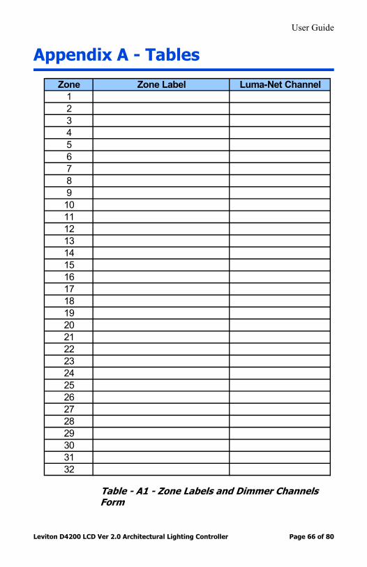
User Guide
Leviton D4200 LCD Ver 2.0 Architectural Lighting Controller Page 66 of 80
Appendix A - Tables
Table - A1 - Zone Labels and Dimmer Channels Form
Zone Zone Label Luma-Net Channel1234567891011121314151617181920212223242526272829303132

User Guide
Leviton D4200 LCD Ver 2.0 Architectural Lighting Controller Page 67 of 80
Table A2 - Scene Labels and Zone Exclusions Form
Scene Scene Label Zones Excluded from Scene
12345678
9101112
Accessible from LCD Station:
Accessible from Entry Station:

User Guide
Leviton D4200 LCD Ver 2.0 Architectural Lighting Controller Page 68 of 80
Table A3 - Scheduling Form
Schedule Event #
Days of the Week
S M T W T F S
Action (Scene #, Max, Off, Seq. On, Seq. Off, Resume, Cell On, Seq. # ) Time
Schedule Event #
Days of the Week
S M T W T F S
Action (Scene #, Max, Off, Seq. On, Seq. Off, Resume, Cell On, Seq. # ) Time
1 332 343 354 365 376 387 398 409 4110 4211 4312 4413 4514 4615 4716 4817 4918 5019 5120 5221 5322 5423 5524 5625 5726 5827 5928 6029 6130 6231 6332 64

User Guide
Leviton D4200 LCD Ver 2.0 Architectural Lighting Controller Page 69 of 80
Table A4 - Sequencer Form
Sequencer Event #
Action (Scene # and Delay, Skip, Goto Step, Loop, Stop, Off and Delay, Max and Delay)
Sequencer Event #
Action (Scene # and Delay, Skip, Goto Step, Loop, Stop, Off and Delay, Max and Delay)
1 332 343 354 365 376 387 398 409 4110 4211 4312 4413 4514 4615 4716 4817 4918 5019 5120 5221 5322 5423 5524 5625 5726 5827 5928 6029 6130 6231 6332 64
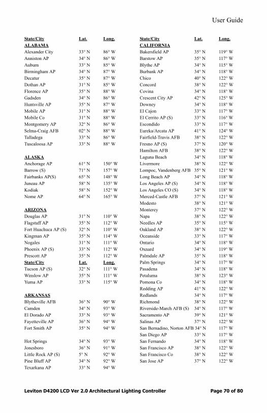
User Guide
Leviton D4200 LCD Ver 2.0 Architectural Lighting Controller Page 70 of 80
State/City Lat. Long.ALABAMAAlexander City 33° N 86° WAnniston AP 34° N 86° WAuburn 33° N 85° WBirmingham AP 34° N 87° WDecatur 35° N 87° WDothan AP 31° N 85° WFlorence AP 35° N 88° WGadsden 34° N 86° WHuntsville AP 35° N 87° WMobile AP 31° N 88° WMobile Co 31° N 88° WMontgomery AP 32° N 86° WSelma-Craig AFB 02° N 88° WTalladega 33° N 86° WTuscaloosa AP 33° N 88° W
ALASKAAnchorage AP 61° N 150° WBarrow (S) 71° N 157° WFairbanks AP(S) 65° N 148° WJuneau AP 58° N 135° WKodiak 58° N 152° WNome AP 64° N 165° W
ARIZONADouglas AP 31° N 110° WFlagstaff AP 35° N 112° WFort Huachuca AP (S) 32° N 110° WKingman AP 35° N 114° WNogales 31° N 111° WPhoenix AP (S) 33° N 112° WPrescott AP 35° N 112° WState/City Lat. Long.Tucson AP (S) 32° N 111° WWinslow AP 35° N 111° WYuma AP 33° N 115° W
ARKANSASBlytheville AFB 36° N 90° WCamden 34° N 93° WEl Dorado AP 33° N 93° WFayetteville AP 36° N 94° WFort Smith AP 35° N 94° W
Hot Springs 34° N 93° WJonesboro 36° N 91° WLittle Rock AP (S) 5° N 92° WPine Bluff AP 34° N 92° WTexarkana AP 33° N 94° W
State/City Lat. Long.CALIFORNIABakersfield AP 35° N 119° WBarstow AP 35° N 117° WBlythe AP 34° N 115° WBurbank AP 34° N 118° WChico 40° N 122° WConcord 38° N 122° WCovina 34° N 118° WCrescent City AP 42° N 125° WDowney 34° N 118° WEl Cajon 33° N 117° WEl Cerrito AP (S) 33° N 116° WEscondido 33° N 117° WEureka/Arcata AP 41° N 124° WFairfield-Travis AFB 38° N 122° WFresno AP (S) 37° N 120° WHamilton AFB 38° N 122° WLaguna Beach 34° N 118° WLivermore 38° N 122° WLompoc, Vandenberg AFB 35° N 121° WLong Beach AP 34° N 118° WLos Angeles AP (S) 34° N 118° WLos Angeles CO (S) 34° N 118° WMerced-Castle AFB 37° N 121° WModesto 38° N 121° WMonterey 37° N 122° WNapa 38° N 122° WNeedles AP 35° N 115° WOakland AP 38° N 122° WOceanside 33° N 117° WOntario 34° N 118° WOxnard 34° N 119° WPalmdale AP 35° N 118° WPalm Springs 34° N 117° WPasadena 34° N 118° WPetaluma 38° N 123° WPomona Co 34° N 118° WRedding AP 41° N 122° WRedlands 34° N 117° WRichmond 38° N 122° WRiverside-March AFB (S) 34° N 117° WSacramento AP 39° N 121° WSalinas AP 37° N 122° WSan Bernadino, Norton AFB 34° N 117° WSan Diego AP 33° N 117° WSan Fernando 34° N 118° WSan Francisco AP 38° N 122° WSan Francisco Co 38° N 122° WSan Jose AP 37° N 122° W
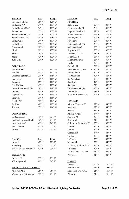
User Guide
Leviton D4200 LCD Ver 2.0 Architectural Lighting Controller Page 71 of 80
State/City Lat. Long.San Louis Obispo 35° N 121° WSanta Ana AP 34° N 118° WSanta Barbara MAP 34° N 120° WSanta Cruz 37° N 122° WSanta Maria AP (S) 35° N 120° WSanta Monica CIC 34° N 118° WSanta Paula 34° N 119° WSanta Rosa 39° N 123° WStockton AP 38° N 121° WUkiah 39° N 123° WVisalia 36° N 119° WYreka 42° N 123° WYuba City 39° N 122° W
COLORADOAlamosa AP 37° N 106° WBoulder 40° N 105° WColorado Springs AP 39° N 105° WDenver AP 40° N 105° W Durango 37° N 108° WFort Collins 41° N 105° WGrand Junction AP (S) 39° N 109° WGreeley 40° N 105° WLajunta AP 38° N 103° WLeadville 39° N 106° WPueblo AP 38° N 104° WSterling 48° N 103° WTrinidad 37° N 104° W
CONNECTICUTBridgeport AP 41° N 73° WHartford, Brainard Field 42° N 73° WNew Haven AP 41° N 74° WNew London 41° N 72° WNorwalk 41° N 73° W
State/City Lat. Long.Norwick 42° N 72° WWaterbury 42° N 73° WWidsor Locks, Bradley Fl 42° N 73° W
DELAWAREDover AFB 39° N 75° WWilmington AP 40° N 76° W
DISTRICT OF COLUMBIAAndrews AFB 38° N 76° WWashington, National AP 39° N 77° W
State/City Lat. Long.FLORIDABelle Glade 27° N 81° WCape Kennedy AP 28° N 81° WDaytona Beach AP 29° N 81° WE Fort Lauderdale 26° N 80° WFort Myers AP 27° N 82° WFort Pierce 27° N 80° WGainesville AP (S) 30° N 82° WJacksonville AP 30° N 82° WKey West AP 25° N 82° WLakeland Co (S) 28° N 82° WMiami AP (S) 26° N 80° WMiami Beach Co 26° N 80° WOcala 29° N 82° WOrlando AP 29° N 81° WPanama City, Tyndall AFB 30° N 86° WPensacola Co 30° N 87° WSt. Augustine 30° N 81° WSt. Petersburg 28° N 83° WStanford 29° N 81° WSarasota 27° N 83° WTallahassee AP (S) 30° N 84° WTampa AP (S) 28° N 83° WWest Palm Beach AP 27° N 80° W
GEORGIAAlbany, Turner AFB 32° N 84° WAmericus 32° N 84° WAthens 33° N 83° WAtlanta AP (S) 34° N 84° WAugusta AP 33° N 82° WBrunswick 31° N 81° WColumbus, Lawson AFB 33° N 85° WDalton 35° N 85° WDublin 32° N 83° WGainesville 34° N 84° WGriffin 33° N 84° WLaGrange 33° N 85° WMacon AP 33° N 84° WMarietta, Dobbins AFB 34° N 85° WSavannah 32° N 81° WValdosta-Moody AFB 31° N 83° WWaycross 31° N 82° W
HAWAIIHilo AP (S) 20° N 155° WHonolulu AP 21° N 158° WKaneohe Bay MCAS 21° N 158° WWahiawa 21° N 158° W
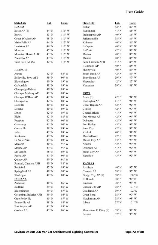
User Guide
Leviton D4200 LCD Ver 2.0 Architectural Lighting Controller Page 72 of 80
State/City Lat. Long.IDAHOBoise AP (S) 44° N 116° WBurley 43° N 114° WCoeur D’Alene AP 48° N 117° WIdaho Falls AP 44° N 112° WLewiston AP 46° N 117° WMoscow 47° N 117° WMountain Home AFB 43° N 116° WPocatello AP 43° N 113° WTwin Falls AP (S) 42° N 114° W
ILLINOISAurora 42° N 88° WBelleville, Scott AFB 39° N 90° WBloomington 40° N 89° WCarbondale 38° N 89° WChampaign/Urbana 40° N 88° WChicago, Midway AP 42° N 88° WChicago, O’Hare AP 42° N 88° WChicago Co 42° N 88° WDanville 40° N 88° WDecatur 40° N 89° WDixon 42° N 89° WElgin 42° N 88° WFreeport 42° N 90° WGalesburg 41° N 90° WGreenville 39° N 89° WJoliet 42° N 88° WKankakee 41° N 88° WLa Salle/Peru 41° N 89° WMacomb 40° N 91° WMoline AP 41° N 91° WMt Vernon 38° N 89° WPeoria AP 41° N 90° WQuincy AP 40° N 91° WRantoul, Chanute AFB 40° N 88° WRockford 42° N 89° WSpringfield AP 40° N 90° WWaukegan 42° N 88° WINDIANAAnderson 40° N 86° WBedford 39° N 86° WBloomington 39° N 87° WColumbus, Bakalar AFB 39° N 86° WCrawfordsville 40° N 87° WEvansville AP 38° N 88° WFort Wayne AP 41° N 85° WGoshen AP 42° N 86° W
State/City Lat. Long.Hobar 42° N 87° WHuntington 41° N 85° WIndianapolis AP 40° N 86° WJeffersonville 38° N 86° WKokomo 40° N 86° WLafayette 40° N 86° WLa Porte 42° N 87° WMarion 40° N 86° WMuncie 40° N 85° WPeru, Grissom AFB 41° N 86° WRichmond AP 40° N 85° WShelbyville 40° N 86° WSouth Bend AP 42° N 86° WTerre Haute AP 39° N 87° WValparaiso 42° N 87° WVincennes 39° N 88° W
IOWAAmes (S) 42° N 94° WBurlington AP 41° N 91° WCedar Rapids AP 42° N 92° WClinton 42° N 90° WCouncil Bluffs 41° N 96° WDes Moines AP 42° N 94° WDubuque 42° N 91° WFort Dodge 43° N 95° WIowa City 42° N 92° WKeokuk 40° N 91° WMarshalltown 42° N 93° WMason City AP 43° N 93° WNewton 42° N 93° WOttumwa AP 41° N 92° WSioux City AP 42° N 96° WWaterloo 43° N 92° W
KANSASAtchison 40° N 95° WChanute AP 38° N 95° WDodge City AP (S) 38° N 100° WEl Dorado 38° N 97°WEmporia 38° N 96° WGarden City AP 38° N 101° WGoodland AP 39° N 102°WGreat Bend 38° N 99° WHutchinson AP 38° N 98° WLibera 37° N 101° W
Manhattan, Ft Riley (S) 39° N 97° WParsons 37° N 96° W

User Guide
Leviton D4200 LCD Ver 2.0 Architectural Lighting Controller Page 73 of 80
State/City Lat. Long.Russell AP 39° N 99° WSalina 39° N 98° WTopeka AP 39° N 96° WWichita AP 38° N 97° W
KENTUCKYAshland 39° N 83° WBowling Green AP 36° N 86° WCorbin AP 37° N 84° W
Covington AP 39° N 85° WHopkinsville, Ft Campbell 37° N 88° WLexington AP (S) 38° N 85° WLouisville AP 38° N 86° WMadisonville 37° N 87° WOwensboro 38° N 87° WPaducah AP 37° N 89° W
LOUISIANAAlexandria AP 31° N 92° WBaton Rouge AP 31° N 91° WBogalusa 31° N 90° WHouma 30° N 91° WLafayette AP 30° N 92° WLake Charles AP (S) 30° N 93° WMinden 33° N 93° WMonroe AP 33° N 92° WNatchitoches 32° N 93° WNew Orleans AP 30° N 90° WShreveport AP (S) 32° N 94° W
MAINEAugusta AP 44° N 70° WBangor, Dow AFB 45° N 69° WCaribou AP (S) 47° N 68° WLewiston 44° N 70° WMillinocket AP 46° N 69° WPortland (S) 44° N 70° WWaterville 45° N 70° W
MARYLANDBaltimore AP 39° N 77° WBaltimore Co 39° N 76° WCumberland 40° N 79° WFrederick AP 40° N 78° WHagerstown 40° N 78° WSalisbury (S) 38° N 75° W
State/City Lat. Long.MASSACHUSETTSBoston AP 42° N 71° WClinton 42° N 72° WFall River 42° N 71° WFramingham 42° N 71° WGloucester 43° N 71° WGreenfield 42° N 72° WLawrence 43° N 71° WLowell 43° N 71° WNew Bedford 42° N 71° WPittsfield AP 42° N 73° WSpringfield, Westover AFB 42° N 73° WTaunton 42° N 71° WWorcester AP 42° N 72° W
MICHIGANAdrian 42° N 84° WAlpena AP 45° N 83° WBattle Creek AP 42° N 85° WBenton Harbor AP 42° N 86° WDetroit 42° N 83° WEscanaba 46° N 87° WFlint AP 43° N 84° WGrand Rapids AP 43° N 86° WHolland 43° N 86° WJackson AP 42° N 84° WKalamazoo 42° N 86° WLansing AP 43° N 85° WMarquette Co 47° N 87° WMt Pleasant 44° N 85° WMuskegon AP 43° N 86° WPontiac 43° N 83° WPort Huron 43° N 82° WSaginaw AP 44° N 84° WSault Ste. Marie AP (S) 46° N 84° WTraverse City AP 45° N 86° WYpsilanti 42° N 84° W
MINNESOTAAlbert Lea 44° N 93° WAlexandria AP 46° N 95° WBemidji AP 48° N 95° WBrainerd 47° N 94° WDuluth AP 47° N 92° WFaribault 44° N 93° WFergus Falls 46° N 96° WInternational Falls AP 49° N 93° WMankato 44° N 93° WMinneapolis/St. Paul AP 45° N 94° WRochester AP 44° N 92° WState/City Lat. Long.
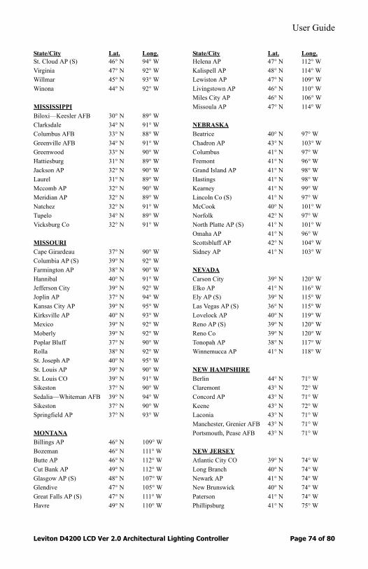
User Guide
Leviton D4200 LCD Ver 2.0 Architectural Lighting Controller Page 74 of 80
State/City Lat. Long.St. Cloud AP (S) 46° N 94° WVirginia 47° N 92° WWillmar 45° N 93° WWinona 44° N 92° W
MISSISSIPPIBiloxi—Keesler AFB 30° N 89° WClarksdale 34° N 91° WColumbus AFB 33° N 88° WGreenville AFB 34° N 91° WGreenwood 33° N 90° WHattiesburg 31° N 89° WJackson AP 32° N 90° WLaurel 31° N 89° WMccomb AP 32° N 90° WMeridian AP 32° N 89° WNatchez 32° N 91° WTupelo 34° N 89° WVicksburg Co 32° N 91° W
MISSOURICape Girardeau 37° N 90° WColumbia AP (S) 39° N 92° WFarmington AP 38° N 90° WHannibal 40° N 91° WJefferson City 39° N 92° WJoplin AP 37° N 94° WKansas City AP 39° N 95° WKirksville AP 40° N 93° WMexico 39° N 92° WMoberly 39° N 92° WPoplar Bluff 37° N 90° WRolla 38° N 92° WSt. Joseph AP 40° N 95° WSt. Louis AP 39° N 90° WSt. Louis CO 39° N 91° WSikeston 37° N 90° WSedalia—Whiteman AFB 39° N 94° WSikeston 37° N 90° WSpringfield AP 37° N 93° W
MONTANABillings AP 46° N 109° WBozeman 46° N 111° WButte AP 46° N 112° WCut Bank AP 49° N 112° WGlasgow AP (S) 48° N 107° WGlendive 47° N 105° WGreat Falls AP (S) 47° N 111° WHavre 49° N 110° W
State/City Lat. Long.Helena AP 47° N 112° WKalispell AP 48° N 114° WLewiston AP 47° N 109° WLivingstown AP 46° N 110° WMiles City AP 46° N 106° WMissoula AP 47° N 114° W
NEBRASKABeatrice 40° N 97° WChadron AP 43° N 103° WColumbus 41° N 97° WFremont 41° N 96° WGrand Island AP 41° N 98° WHastings 41° N 98° WKearney 41° N 99° WLincoln Co (S) 41° N 97° WMcCook 40° N 101° WNorfolk 42° N 97° WNorth Platte AP (S) 41° N 101° WOmaha AP 41° N 96° WScottsbluff AP 42° N 104° WSidney AP 41° N 103° W
NEVADACarson City 39° N 120° WElko AP 41° N 116° WEly AP (S) 39° N 115° WLas Vegas AP (S) 36° N 115° WLovelock AP 40° N 119° WReno AP (S) 39° N 120° WReno Co 39° N 120° WTonopah AP 38° N 117° WWinnemucca AP 41° N 118° W
NEW HAMPSHIREBerlin 44° N 71° WClaremont 43° N 72° WConcord AP 43° N 71° WKeene 43° N 72° WLaconia 43° N 71° WManchester, Grenier AFB 43° N 71° WPortsmouth, Pease AFB 43° N 71° W
NEW JERSEYAtlantic City CO 39° N 74° WLong Branch 40° N 74° WNewark AP 41° N 74° WNew Brunswick 40° N 74° WPaterson 41° N 74° WPhillipsburg 41° N 75° W

User Guide
Leviton D4200 LCD Ver 2.0 Architectural Lighting Controller Page 75 of 80
State/City Lat. Long.Trenton Co 40° N 75° WVineland 39° N 75° W
NEW MEXICOHolloman AFB 33° N 106° WAlbuquerque AP (S) 35° N 107° WArtesia 33° N 104° WCarlsbad AP 32° N 104° WClovis AP 34° N 103° WFarmington AP 37° N 108° WGallup 36° N 109° WGrants 35° N 108° WHobbs AP 33° N 103° WLas Cruces 32° N 107° WLos Alamos 36° N 106° WRaton AP 37° N 104° WRoswell, Walker AFB 33° N 105° WSanta Fe CO 36° N 106° WSilver City AP 33° N 108° WSocorro AP 34° N 107° WTucumcari AP 35° N 104° W
NEW YORKAlbany AP (S) 43° N 74° WAlbany Co 43° N 74° WAuburn 43° N 77° WBatavia 43° N 78° WBinghamton AP 42° N 76° WBuffalo AP 43° N 79° WCortland 43° N 76° WDunkirk 42° N 79° WElmira AP 42° N 77° WGeneva (S) 43° N 77° WGlens Falls 43° N 74° WGloversville 43° N 74° WHornell 42° N 78° WIthaca (S) 42° N 76° W Jamestown 42° N 79° WKingston 42° N 74° WLockport 43° N 79° WMassena AP 45° N 75° WNewburgh, Stewart AFB 41° N 74° WNYC-Central Park (S) 41° N 74° WNYC-Kennedy AP 41° N 74° WNYC-La Guardia AP 41° N 74° WNiagara Falls AP 43° N 80° WOlean 42° N 79° WOneonta 43° N 75° WOswego Co 43° N 77° W
State/City Lat. Long.Plattsburg AFB 45° N 73° WPoughkeepsie 42° N 74° WRochester AP 43° N 78° WRome, Griffiss AFB 43° N 75° WSchenectady (S) 43° N 74° WSuffolk County AFB 41° N 73° WSyracuse AP 43° N 76° WUtica 43° N 75° WWatertown 44° N 76° W
NORTH CAROLINAAsheville AP 35° N 83° WCharlotte AP 35° N 81° WDurham 36° N 79° WElizabeth City AP 36° N 76° WFayetteville, Pope AFB 35° N 79° WGoldsboro,Seymour-Johnson35° N 78° WGreensboro AP (S) 36° N 80° WGreenville 36° N 77° WHenderson 36° N 78° WHickory 06° N 81° WJacksonville 35° N 78° WLumberton 35° N 79° WNew Bern AP 35° N 77° WRaleigh/Durham AP (S) 36° N 79° WRocky Mount 36° N 78° WWilmington AP 34° N 78° WWinston-Salem AP 36° N 80° W
NORTH DAKOTABismarck AP (S) 47° N 101° WDevils Lake 48° N 99° WDickinson AP 47° N 103° WFargo AP 47° N 97° WGrand Forks AP 48° N 97° WJamestown AP 47° N 99° WMinot AP 48° N 101° WWilliston 48° N 104° W
OHIOAkron-Canton AP 41° N 81° WAshtabula 42° N 81° WAthens 39° N 82° WBowling Green 41° N 84° WCambridge 40° N 82° WChillicothe 39° N 83° WCincinnati Co 39° N 85° WCleveland AP (S) 41° N 82° WColumbus AP (S) 40° N 83° W

User Guide
Leviton D4200 LCD Ver 2.0 Architectural Lighting Controller Page 76 of 80
State/City Lat. Long.Dayton AP 40° N 84° WDefiance 41° N 84° WFindlay AP 41° N 84° WFremont 41° N 83° WHamilton 39° N 85° WLancaster 40° N 83° WLima 41° N 84° WMansfield AP 41° N 83° WMarion 41° N 83° WMiddletown 40° N 84° WNewark 40° N 82° WNorwalk 41° N 83° WPortsmouth 39° N 83° WSandusky Co 41° N 83° WSpringfield 40° N 84° WSteubenville 40° N 81° WToledo AP 42° N 84° WWarren 41° N 81° WWooster 41° N 82° WYoungstown AP 41° N 81° WZanesville AP 40° N 82° W
OKLAHOMAAda 35° N 97° WAltus AFB 35° N 99° WArdmore 34° N 97° WBartlesville 37° N 96° WChickasha 35° N 98° WEnid, Vance AFB 36° N 98° WLawton AP 35° N 98° WMcAlester 35° N 96° WMuskogee AP 36° N 95° WNorman 35° N 97° WOklahoma City AP (S) 35° N 98° WPonca City 37° N 97° WSeminole 35° N 97° WStillwater (S) 36° N 97° WTulsa AP 36° N 96° WWoodward 37° N 100° W
OREGONAlbany 45° N 123° WAstoria AP (S) 46° N 124° WBaker AP 45° N 118° WBend 44° N 121° WCorvallis (S) 44° N 123° WEugene AP 44° N 123° WGrants Pass 42° N 123° WKlamath Falls AP 42° N 122° W
State/City Lat. Long.Medford AP (S) 42° N 123° WPendleton AP 46° N 119° WPortland AP 46° N 123° WPortland Co 46° N 123° WRoseburg AP 43° N 123° WSalem AP 45° N 123° WThe Dalles 46° N 121° W
PENNSYLVANIAAllentown AP 41° N 75° WAltoona Co 40° N 78° WButler 41° N 80° WChambersburg 40° N 78° WErie AP 42° N 80° WHarrisburg AP 40° N 77° WJohnstown 40° N 79° WLancaster 40° N 76° WMeadville 42° N 80° WNew Castle 41° N 80° WPhiladelphia AP 40° N 75° WPittsburgh AP 40° N 80° WPittsburgh Co 40° N 80° WReading Co 40° N 76° WScranton/Wilkes-Barre 41° N 76° WState College (S) 41° N 78° WSunbury 41° N 77° WUniontown 40° N 80° WWarren 42° N 79° WWest Chester 40° N 76° WWilliamsport AP 41° N 77° WYork 40° N 77° W
RHODE ISLANDNewport (S) 41° N 71° WProvidence AP 42° N 71° W
SOUTH CAROLINAAnderson 34° N 83° WCharleston AFB (S) 33° N 80° WCharleston Co 33° N 80° WColumbia AP 34° N 81° WFlorence AP 35° N 80° WGeorgetown 33° N 79° WGreenville AP 35° N 82° WGreenwood 35° N 82° WOrangeburg 33° N 81° WRock Hil 35° N 81° WSpartanburg AP 35° N 82° WSumter, Shaw AFB 34° N 80° W
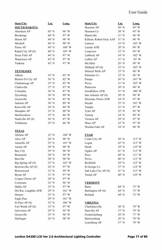
User Guide
Leviton D4200 LCD Ver 2.0 Architectural Lighting Controller Page 77 of 80
State/City Lat. Long.SOUTH DAKOTAAberdeen AP 45° N 98° WBrookings 44° N 97° WHuron AP 44° N 98° WMitchell 44° N 98° WPierre AP 44° N 100° WRapid City AP (S) 44° N 103° WSioux Falls AP 44° N 97° WWatertown AP 45° N 97° WYankton 43° N 97° W
TENNESSEEAthens 35° N 85° WBristol-Tri City AP 36° N 82° WChattanooga AP 35° N 85° WClarksville 37° N 87° WColumbia 36° N 87° WDyersburg 36° N 89° WGreenville 36° N 83° WJackson AP 36° N 89° WKnoxville AP 36° N 84° WMemphis AP 35° N 90° WMurfreesboro 35° N 86° WNashville AP (S) 36° N 87° WTullahoma 35° N 86° W
TEXASAbilene AP 32° N 100° WAlice AP 28° N 98° WAmarillo AP 35° N 101° WAustin AP 30° N 98° WBay City 29° N 96° WBeaumont 30° N 94° WBeeville 28° N 98° WBig Spring AP (S) 32° N 101° WBrownsville AP (S) 26° N 97° WBrownwood 32° N 99° WBryan AP 31° N 97° WCorpus Christi AP 28° N 97° WCorsicana 32° N 96° WDallas AP 33° N 97° WDel Rio, Laughlin AFB 29° N 101° WDenton 33° N 97° WEagle Pass 29° N 101° WEl Paso AP (S) 32° N 106° WFort Worth AP (S) 33° N 97° WGalveston AP 29° N 95° WGreenville 33° N 96° WHarlingen 26° N 98° W
State/City Lat. Long.Houston AP 30° N 95° WHouston Co 30° N 95° WHuntsville 31° N 96° WKilleen, Robert Gray AAF 31° N 98° WLamesa 33° N 102° WLaredo AFB 28° N 99° WLongview 32° N 95° WLubbock AP 34° N 102° WLufkin AP 31° N 95° WMcAllen 26° N 98° WMidland AP (S) 32° N 102° WMineral Wells AP 33° N 98° WPalestine Co 32° N 96° WPampa 36° N 101° WPecos 31° N 103° WPlainview 30° N 94° WGoodfellow AFB 31° N 100° WSan Antonio AP (S) 30° N 98° WSherman, Perrin AFB 34° N 97° WSnyder 33° N 101° WTemple 31° N 97° WTyler AP 32° N 95° WVernon 34° N 99° WVictoria AP 29° N 97° WWaco AP 32° N 97° WWichita Falls AP 34° N 98° W
UTAHCedar City AP 38° N 113° WLogan 42° N 112° WMoab 39° N 110° WOgden AP 41° N 112° WPrice 40° N 111° WProvo 40° N 112° WRichfield 39° N 112° WSt George Co 37° N 114° WSalt Lake City AP (S) 41° N 112° WVernal AP 40° N 110° W
VERMONTBarre 44° N 73° WBurlington AP (S) 44° N 73° WRutland 44° N 73° W
VIRGINIACharlottesville 38° N 79° WDanville AP 37° N 79° WFredericksburg 38° N 77° WHarrisonburg 38° N 79° WLynchburg AP 37° N 79° W
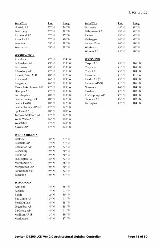
User Guide
Leviton D4200 LCD Ver 2.0 Architectural Lighting Controller Page 78 of 80
State/City Lat. Long.Norfolk AP 37° N 76° WPetersburg 37° N 78° WRichmond AP 37° N 77° WRoanoke AP 37° N 80° WStaunton 38° N 79° WWinchester 39° N 78° W
WASHINGTONAberdeen 47° N 124° WBellingham AP 49° N 123° WBremerton 48° N 123° WEllensburg AP 47° N 121° WEverett, Paine AFB 48° N 122° WKennewick 46° N 119° WLongview 46° N 123° WMoses Lake, Larson AFB 47° N 119° WOlympia AP 47° N 123° WPort Angeles 48° N 123° WSeattle-Boeing Field 48° N 122° WSeattle Co (S) 48° N 122° WSeattle-Tacoma AP (S) 47° N 122° WSpokane AP (S) 48° N 118° WTacoma, McChord AFB 47° N 122° WWalla Walla AP 46° N 118° WWenatchee 47° N 120° WYakima AP 47° N 121° W
WEST VIRGINIABeckley 38° N 81° WBluefield AP 37° N 81° WCharleston AP 38° N 82° WClarksburg 39° N 80° WElkins AP 39° N 80° WHuntington Co 38° N 82° WMartinsburg AP 39° N 78° WMorgantown AP 40° N 80° WParkersburg Co 39° N 82° WWheeling 40° N 81° W
WISCONSINAppleton 44° N 88° WAshland 47° N 91° WBeloit 42° N 89° WEau Claire AP 45° N 91° WFond Du Lac 44° N 88° WGreen Bay AP 44° N 88° WLa Crosse AP 44° N 91° WMadison AP (S) 43° N 89° WManitowoc 44° N 87° W
State/City Lat. Long.Marinette 45° N 88° WMilwaukee AP 43° N 88° WRacine 43° N 88° WSheboygan 44° N 88° WStevens Point 44° N 90° WWaukesha 43° N 88° WWausau AP 45° N 90° W
WYOMINGCasper AP 43° N 106° WCheyenne 41° N 105° WCody AP 45° N 109° WEvanston 41° N 111° WLander AP (S) 43° N 109° WLaramie AP (S) 41° N 106° WNewcastle 44° N 104° WRawlins 42° N 107° WRock Springs AP 42° N 109° WSheridan AP 45° N 107° WTorrington 42° N 104° W

User Guide
Leviton D4200 LCD Ver 2.0 Architectural Lighting Controller Page 79 of 80
Appendix C - Miscellaneous Information
Clearing the Memory If you have problems and cannot remedy the situation, you can clear the memory and start over. Please use this only as a last remedy to any problems.
The stations might have been programmed at the factory. If you clear the memory you will lose all the factory programming and have to start over assigning numbers, dimmers, etc.
To clear the memory:1: Press and hold the Menu/Cancel button for 10 seconds, until
LEVITON appears on the LCD display.2: Immediately release the Menu/Cancel button.3: Press and hold the Master Down button until the LCD
display shows INITIALIZING DEFAULTS. Once LEVITON appears on the LCD display, the memory is reset to the factory default values.

User Guide
Leviton D4200 LCD Ver 2.0 Architectural Lighting Controller Page 80 of 80
Warranty Information
WarrantyLEVITON LIGHTING CONTROL DIVISION of Leviton Manufacturing Co Inc. warrants its Dimmer Systems and Controls to be free of material and workmanship defects for a period of two years after system acceptance or 26 months after shipment, whichever comes first. This Warranty is limited to repair of replacement of defective equipment returned Freight Pre-Paid to Leviton Lighting Control Division at 20497 Teton Ave., Tualatin, Oregon 97062, USA. User shall call 1-800-959-6004 and request a return authorization number to mark on the outside of the returning carton, to assure that the returned material will be properly received at Leviton. All equipment shipped back to Leviton must be carefully and properly packed to avoid shipping damage. Replacements or repaired equipment will be returned to sender freight prepaid, F.O.B. factory. Leviton is not responsible for removing or replacing equipment on the job site, and will not honor charges for such work. Leviton will not be responsible for any loss of use time or subsequent damages should any of the equipment fail during the warranty period, but agrees only to repair or replace defective equipment returned to its plant in Tualatin, Oregon. This Warranty is void on any product that has been improperly installed, overloaded, short circuited, abused, or altered in any manner. Neither the seller nor Leviton shall be liable for any injury, loss or damage, direct or consequential arising out of the use of or inability to use the equipment. This Warranty does not cover lamps, ballasts, and other equipment which is supplied or warranted directly to the user by their manufacturer. Leviton makes no warranty as to the Fitness for Purpose or other implied Warranties.

NOTES:

NOTES:

Leviton Lighting Control Division Headquarters20497 SW Teton Avenue, Tualatin, OR 97062Customer Service Telephone: 1-800-736-6682 • FAX: 1-503-404-5600Tech Line: 1-800-959-6004
Leviton Manufacturing Co., Inc.59-25 Little Neck Parkway, Little Neck, NY 11362-2591Telephone: 1-800-323-8920 • FAX: 1-800-832-9538
Visit Leviton’s Web site at http://www.leviton.com and http://www.nsicorp.com© 2002 Leviton Manufacturing Co., Inc. All Rights ReservedSpecifications and Pricing Subject to Change at any time
LIT-D4200-00 mod 10/29/02