D4. GEOLOGY OF STONE MOUNTAIN - NASA · STONE MOUNTAIN 109 A block field, radial to and possibly...
22
D4. GEOLOGY OF STONE MOUNTAIN By ANTHONY G. SANCHEZ CONTENTS Page Introduction …………………………………………………………………………………………………… 107 Geology of the station areas ………………………………………………………………………………….. 108 Station 4 ………………………………………………………………………………………………………. 108 Station 5 ………………………………………………………………………………………………………. 111 Station 6 ………………………………………………………………………………………………………. 115 Discussion and summary ……………………………………………………………………………………… 122 ILLUSTRATIONS Page FIGURE 1. Photograph showing location of traverses 1 and 2 and Stone mountain area …………………………………………………………………….. 107 2. Telephotographic mosaic of Stone mountain taken from station 2 ……………………………………………………………………………….. 108 3. Photograph of station 4 and vicinity ………………………………………………………………………………………………………………. 109 4. Planimetric map of station 4 ………………………………………………………………………………………………………………………. 109 5--11. Photographs: 5. Sample 64425 ………………………………………………………………………………………………………………………….. 110 6. Sample 64435 with photomicrographs ………………………………………………………………………………………………… 111 7. Stereopair, sample 64475 ……………………………………………………………………………………………………………… 113 8. Stereopair, sample 64476 ……………………………………………………………………………………………………………… 113 9. Sample 64535 …………………………………………………………………………………………………………………………. 113 10. Sample 64455 with photomicrographs ………………………………………………………………………………………………… 114 11. Sample 64815 ………………………………………………………………………………………………………………………….. 114 12. Map showing block distribution within 10 m of station 4a panorama …………………………………………………………………………… 114 13. Photograph of station 5 and vicinity ……………………………………………………………………………………………………………… 115 14. Planimetric map of station 5 ……………………………………………………………………………………………………………………… 115 15. Map showing block distribution within 10 m of station 5 panorama …………………………………………………………………………….. 116 16-22. Photographs: 16. Stereopair of sample 65035 …………………………………………………………………………………………………………….. 116 17. Sample 65075 …………………………………………………………………………………………………………………………... 117 18. Stereopair of sample 65095 …………………………………………………………………………………………………………….. 117 19. Stereopair and photomicrographs of sample 65315 ……………………………………………………………………………………. 118 20. Stereopair and photomicrographs of sample 65055 ……………………………………………………………………………………. 119 21. Stereopair of sample 65015 …………………………………………………………………………………………………………….. 120 22. Station 6 and vicinity …………………………………………………………………………………………………………………… 120 23. Topographic map of the Stone mountain area ……………………………………………………………………………………………………. 121 24. Planimetric map of station 6 ……………………………………………………………………………………………………………………… 122 25. Map showing block distribution with 10 m of station 6 panorama ………………………………………………………………………………. 122 26-30. Photographs: 26. Sample 66075 …………………………………………………………………………………………………………………………... 123 27. Stereopair and photomicrograph of sample 66035 ……………………………………………………………………………………... 124 28. Stereopair of sample 66055 …………………………………………………………………………………………………………….. 124 29. Stereo and photomicrographs of sample 66095 ………………………………………………………………………………………… 125 30. Stone mountain traverse showing location of boulder fields identified on 16 mm photographs ………………………………………. 126 TABLES Page TABLE 1.Block shape and size distribution at stations 4, 5, and 6 ………………………………………………………………………………………. 109 106
Transcript of D4. GEOLOGY OF STONE MOUNTAIN - NASA · STONE MOUNTAIN 109 A block field, radial to and possibly...

D4. GEOLOGY OF STONE MOUNTAIN
By ANTHONY G. SANCHEZ
CONTENTS Page
Introduction …………………………………………………………………………………………………… 107 Geology of the station areas ………………………………………………………………………………….. 108 Station 4 ………………………………………………………………………………………………………. 108 Station 5 ………………………………………………………………………………………………………. 111 Station 6 ………………………………………………………………………………………………………. 115 Discussion and summary ……………………………………………………………………………………… 122
ILLUSTRATIONS Page
FIGURE 1. Photograph showing location of traverses 1 and 2 and Stone mountain area …………………………………………………………………….. 107 2. Telephotographic mosaic of Stone mountain taken from station 2 ……………………………………………………………………………….. 108 3. Photograph of station 4 and vicinity ………………………………………………………………………………………………………………. 109 4. Planimetric map of station 4 ………………………………………………………………………………………………………………………. 109 5--11. Photographs: 5. Sample 64425 ………………………………………………………………………………………………………………………….. 110 6. Sample 64435 with photomicrographs ………………………………………………………………………………………………… 111 7. Stereopair, sample 64475 ……………………………………………………………………………………………………………… 113 8. Stereopair, sample 64476 ……………………………………………………………………………………………………………… 113 9. Sample 64535 …………………………………………………………………………………………………………………………. 113 10. Sample 64455 with photomicrographs ………………………………………………………………………………………………… 114 11. Sample 64815 ………………………………………………………………………………………………………………………….. 114
12. Map showing block distribution within 10 m of station 4a panorama …………………………………………………………………………… 114 13. Photograph of station 5 and vicinity ……………………………………………………………………………………………………………… 115 14. Planimetric map of station 5 ……………………………………………………………………………………………………………………… 115 15. Map showing block distribution within 10 m of station 5 panorama …………………………………………………………………………….. 116 16-22. Photographs:
16. Stereopair of sample 65035 …………………………………………………………………………………………………………….. 116 17. Sample 65075 …………………………………………………………………………………………………………………………... 117 18. Stereopair of sample 65095 …………………………………………………………………………………………………………….. 117 19. Stereopair and photomicrographs of sample 65315 ……………………………………………………………………………………. 118 20. Stereopair and photomicrographs of sample 65055 ……………………………………………………………………………………. 119 21. Stereopair of sample 65015 …………………………………………………………………………………………………………….. 120 22. Station 6 and vicinity …………………………………………………………………………………………………………………… 120
23. Topographic map of the Stone mountain area ……………………………………………………………………………………………………. 121 24. Planimetric map of station 6 ……………………………………………………………………………………………………………………… 122 25. Map showing block distribution with 10 m of station 6 panorama ………………………………………………………………………………. 122
26-30. Photographs: 26. Sample 66075 …………………………………………………………………………………………………………………………... 123 27. Stereopair and photomicrograph of sample 66035 ……………………………………………………………………………………... 124 28. Stereopair of sample 66055 …………………………………………………………………………………………………………….. 124 29. Stereo and photomicrographs of sample 66095 ………………………………………………………………………………………… 125 30. Stone mountain traverse showing location of boulder fields identified on 16 mm photographs ………………………………………. 126
TABLES
Page
TABLE 1.Block shape and size distribution at stations 4, 5, and 6 ………………………………………………………………………………………. 109
106

STONE MOUNTAIN
INTRODUCTION
107
Crown, 100 m in diameter, and two nearby unnamed craters, 80 m and 140 m in diameter; most range from 50 m down to the limit of resolution. The crater density on Stone mountain is qualitatively the same as that on the adjacent Cayley plains, but craters larger than 100 m are more abundant on the plains (fig. 1; see also Freeman, this volume). None of the resolvable primary craters on Stone mountain appear to be younger than
Stone mountain is a westward projection of the Descartes mountains extending into the southeastern part of the Apollo 16 traverse area. It is approximately 550 m above the Cayley plains and has a domical morphology.
The largest craters on Stone mountain include
FIGURE 1.- Location of traverses 1 and 2, features discussed in text, and areas covered by figures 3, 13. and 22. Apollo 16 panoramic camera frame 4618.

GEOLOGY OF THE APOLLO 16 AREA, CENTRAL LUNAR HIGHLANDS 108
the prominent South Ray and Baby Ray craters on the plains.
The average thickness of the regolith on Stone mountain based on radar data and concentric craters (Freeman, this volume) is estimated to be about 7 m. The surface is relatively smooth and undulating. The upper part of the regolith on Stone mountain probably includes ejecta from South Ray crater over much of the surface.
GEOLOGY OF THE STATION AREAS The main objective of the sampling at stations 4, 5, and
6 was to collect materials characteristic of the Descartes mountains. This task was constrained by lack of outcrops, difficulty of recognizing craters that penetrated bedrock, contamination by South Ray ejecta, and the lack of obvious characteristics by which to distinguish Descartes material from Cayley. The contact between Cayley and Descartes material was not recognized on the ground; the crew noted the gradual increase in slope but observed no apparent difference in color or texture of regolith.
Station 4, the highest point reached, was about 150 m above the plain on Stone mountain (fig. 2) on a steep slope that was more blocky than expected owing to blocky ray material from South Ray crater. Station 5, lower on the slope and approximately 550 m north of station 4, was on a gently sloping bench near a 15-m crater in an area sparsely covered with blocks. Station 6 was on the edge of the Cayley plains at the base of Stone mountain. A subdued 10-m crater and several small craters are present in the station 6 area, and small blocks are fairly common.
The traverse route on Stone mountain is sprinkled with blocks in the 10- to 100-cm size range interspersed with smaller rocks down to the limit of resolution (2 cm). The crew observed that blocks less than 30 cm in size are the most abundant. Their observations were confirmed by block counts made from the station panorama (pl. 6, pans 9-12; table 1).
STATION 4 As a result of this study the location of station 4 has
been redetermined at about 100 m east of the location reported earlier in Muehlberger and others (1972); the new location places the LRV on the outer part of the ejecta blanket of Cinco a crater. Two localities were occupied at station 4: station 4a (the LRV parking spot and principal sampling area, inside the northeast rim of a subdued doublet crater approximately 15 m across), approximately 40 m west of the rim of Cinco a crater, and 4b, about 50 m south of the LRV (figs. 3 and 4 ). The regional slope averages 10-15° down toward the northwest.
FIG
UR
E 2
.- St
one
mou
ntai
n sh
owin
g lo
catio
ns o
f st
atio
n 4,
5, a
nd 6
and
trav
erse
line
. Mos
aic
of 5
00-mm
pho
togr
aphs
fro
m s
tatio
n 2.
AS1
6 - 1
12-1
8200
, 02,
17,
19,
27
-32.

GEOLOGY OF THE APOLLO 16 AREA, CENTRAL LUNAR HIGHLANDS 108
the prominent South Ray and Baby Ray craters on the plains.
The average thickness of the regolith on Stone mountain based on radar data and concentric craters (Freeman, this volume) is estimated to be about 7 m. The surface is relatively smooth and undulating. The upper part of the regolith on Stone mountain probably includes ejecta from South Ray crater over much of the surface.
GEOLOGY OF THE STATION AREAS The main objective of the sampling at stations 4, 5, and
6 was to collect materials characteristic of the Descartes mountains. This task was constrained by lack of outcrops, difficulty of recognizing craters that penetrated bedrock, contamination by South Ray ejecta, and the lack of obvious characteristics by which to distinguish Descartes material from Cayley. The contact between Cayley and Descartes material was not recognized on the ground; the crew noted the gradual increase in slope but observed no apparent difference in color or texture of regolith.
Station 4, the highest point reached, was about 150 m above the plain on Stone mountain (fig. 2) on a steep slope that was more blocky than expected owing to blocky ray material from South Ray crater. Station 5, lower on the slope and approximately 550 m north of station 4, was on a gently sloping bench near a 15-m crater in an area sparsely covered with blocks. Station 6 was on the edge of the Cayley plains at the base of Stone mountain. A subdued 10-m crater and several small craters are present in the station 6 area, and small blocks are fairly common.
The traverse route on Stone mountain is sprinkled with blocks in the 10- to 100-cm size range interspersed with smaller rocks down to the limit of resolution (2 cm). The crew observed that blocks less than 30 cm in size are the most abundant. Their observations were confirmed by block counts made from the station panorama (pl. 6, pans 9-12; table 1 ).
STATION 4 As a result of this study the location of station 4 has
been redetermined at about 100 m east of the location reported earlier in Muehlberger and others (1972); the new location places the LRV on the outer part of the ejecta blanket of Cinco a crater. Two localities were occupied at station 4: station 4a (the LRV parking spot and principal sampling area, inside the northeast rim of a subdued doublet crater approximately 15 m across), approximately 40 m west of the rim of Cinco a crater, and 4b, about 50 m south of the LRV (figs. 3 and 4 ). The regional slope averages 10-15° down toward the northwest.
FIG
UR
E 2
.- St
one
mou
ntai
n sh
owin
g lo
catio
ns o
f st
atio
n 4,
5, a
nd 6
and
trav
erse
line
. Mos
aic
of 5
00-mm
pho
togr
aphs
fro
m s
tatio
n 2.
AS1
6 - 1
12-1
8200
, 02,
17,
19,
27
-32.
STONE MOUNTAIN 109
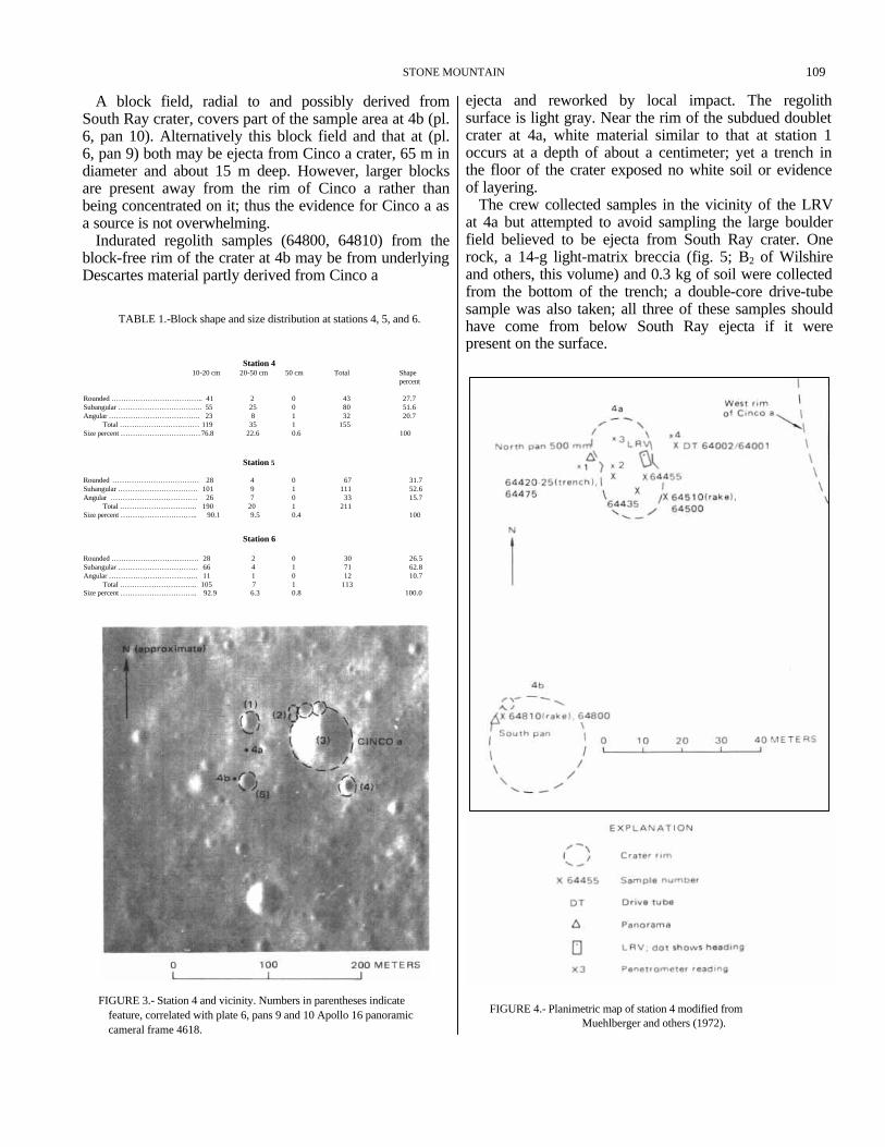
A block field, radial to and possibly derived from South Ray crater, covers part of the sample area at 4b (pl. 6, pan 10). Alternatively this block field and that at (pl. 6, pan 9) both may be ejecta from Cinco a crater, 65 m in diameter and about 15 m deep. However, larger blocks are present away from the rim of Cinco a rather than being concentrated on it; thus the evidence for Cinco a as a source is not overwhelming.
Indurated regolith samples (64800, 64810) from the block-free rim of the crater at 4b may be from underlying Descartes material partly derived from Cinco a
ejecta and reworked by local impact. The regolith surface is light gray. Near the rim of the subdued doublet crater at 4a, white material similar to that at station 1 occurs at a depth of about a centimeter; yet a trench in the floor of the crater exposed no white soil or evidence of layering.
The crew collected samples in the vicinity of the LRV at 4a but attempted to avoid sampling the large boulder field believed to be ejecta from South Ray crater. One rock, a 14-g light-matrix breccia (fig. 5; B2 of Wilshire and others, this volume) and 0.3 kg of soil were collected from the bottom of the trench; a double-core drive-tube sample was also taken; all three of these samples should have come from below South Ray ejecta if it were present on the surface.
TABLE 1.-Block shape and size distribution at stations 4, 5, and 6.
Station 4 10-20 cm 20-50 cm 50 cm Total Shape percent
Rounded ……………………………….. 41 2 0 43 27.7 Subangular …………………………….. 55 25 0 80 51.6 Angular ……………………………….. 23 8 1 32 20.7 Total …………………………… 119 35 1 155 Size percent …………………………… 76.8 22.6 0.6 100
Station 5
Rounded ……………………………… 28 4 0 67 31.7 Suhangular …………………………… 101 9 1 111 52.6 Angular ……………………………… 26 7 0 33 15.7 Total ………………………….. 190 20 1 211 Size percent ………………………….. 90.1 9.5 0.4 100
Station 6
Rounded ……………………………… 28 2 0 30 26.5 Subangular …………………………… 66 4 1 71 62.8 Angular ………………………………. 11 1 0 12 10.7
Total ………………………….. 105 7 1 113 Size percent ………………………….. 92.9 6.3 0.8 100.0
FIGURE 3.- Station 4 and vicinity. Numbers in parentheses indicate feature, correlated with plate 6, pans 9 and 10 Apollo 16 panoramic cameral frame 4618.
FIGURE 4.- Planimetric map of station 4 modified from Muehlberger and others (1972).
STONE MOUNTAIN

GEOLOGY OF THE APOLLO 16 AREA, CENTRAL LUNAR HIGHLANDS 110
FIGURE 5.-Sample 64425; light-matrix dark-clast breccia from bottom of trench at station 4a (NASA photograph S-72-41584).
At station 4b, the blocks are mainly light colored although glass and dust coatings obscure many rock surfaces. Breccia is the predominant rock type in the area, and light clasts are visible in some of the blocks photographed (pl. 6, pan 10). Soil and rake samples consisting mainly of friable, poorly consolidated clods were collected from the northwest rim. No white soil or evidence of layering was found beneath the surface. The blocks on the northeast wall of the crater apparently are breccias containing mainly light but some dark matrices.
The most abundant rocks sampled at station 4, according to Wilshire and others (this volume), were light-matrix dark-clast breccias (B2) and dark-matrix light-clast breccias (B4). Their data, however, are heavily weighted by rake simples, and as they point out, many of the small fragments are probably clasts from larger rocks. Eight samples weighing 25 g or more were collected at station 4a, none at 4b. Seven of the samples from 4a are light-matrix dark-clast breccias; one is a metaclastic crystalline rock. From the location of 4a, well within the ejecta blanket of Cinco a, these larger fragments may be taken as characteristic of underlying rocks in the area. Sample 64435 (fig. 6A), the largest light-matrix (B2) breccia collected at this station, is described as a cataclastic two-pyroxene, olivine-bearing anorthosite, partly coated with a glass rind (Wilshire and others, this volume). In thin section it appears to consist mainly of crushed feldspar invaded by dark matrix material (fig. 6B, C). Samples 64475, 64476, and 64535 (figs. 7-9) are additional examples of B2 breccias collected at station 4. Probably
most of, these samples were deposited as ejecta from South Ray, although the crew attempted to avoid the block field. Other samples collected at this station include a glass-coated anorthosite (64455, fig. 10) and a crushed, annealed mafic rock (64815, fig. 11), both classified as metaclastic (C2) by Wilshire and others (this volume). A K-Ar crystallization age of 3.9+/-0.2 b.y. is reported for 64421 ( Kirsten and others, (1973 ) and an exposure age of 210 m.y. for soil samples 64421 and 64501. These soils probably are not part of South Ray ejecta, as reliable exposure ages of 2 to 4 m.y. have been reported for rocks believed to be South Ray material collected at stations 3 and 9 (see Reed, this volume).
Within the doublet crater at station 4a, blocks are much less numerous on the southwest wall, a distribution suggesting that this side was probably shielded from South Ray ejecta. Approximately 2 percent of the surface at station 4a is covered by rocks more than 10 cm across; blocks as large as 0.8 m are scattered over the area (Muehlberger and others, (1972). Rocks less than about 5 cm across are abundant. Most of the blocks are angular, a characteristic of the ejecta believed to be from South Ray crater, but some of the smaller blocks are subround to round (table 1, fig. 12). The angular, perched appearance of the blocks near the LRV suggests derivation from South Ray crater.
At station 4b, angular blocks are concentrated on the northeast wall and rim of the crater, the rest of the rim being relatively block free. At station 4b (pl. 6, pan 10), the east wall of a 20-m crater appears to be plastered with blocks that have destroyed the raised rim of the

STONE MOUNTAIN 111
crater. As these blocks appear to be ejecta from South Ray, samples were collected only from the northwest interior wall of the crater, shielded from the South Ray ejecta by being on the uprange side. The strongly asymmetric distribution of these blocks, the lack of recognizable ejecta elsewhere around the crater, the partly buried rim under the block-covered area, and the relatively large size of the crater suggest that it is
not of secondary origin but was formed prior to South Ray and was subsequently mantled by South Ray ejecta.
STATION 5 At station 5, the LRV was parked near the north rim of
a 20-m crater (figs. 13, 14; pl. 6, pan 11). Blocks are asymmetrically distributed within the crater; their
FIGURE 6.-Sample 64435. B2 breccia from station 4. A, NASA photograph S-72-39674. B, Photomicrograph of 64435,73 showing glass rind dark material, right) and moderately fractured plagioclase feldspar (left). Plane-polarized light. C, Same as B, cross-polarized light.
A

FIGURE 6.-Continued.
GEOLOGY OF THE APOLLO 16 AREA, CENTRAL LUNAR HIGHLANDS 112

113 STONE MOUNTAIN
FIGURE 7-Stereopair of sample 64475, a coherent B2 breccia from station 4 (NASA photographs S-72-43089-43089B).
FIGURE 8.-Stereopair of sample 64476, a coherent B2 breccia from station 4 (NASA photographs S-72-43114-43114B).
FIGURE 9.- Sample 64535, a highly fractured B2 breccia from station 4 (NASA photograph S72--43420).

GEOLOGY OF THE APOLLO 16 AREA, CENTRAL LUNAR HIGHLANDS 114
FIGURE 11.- Sample 64815, an unusually mafic fragment from station 4. NASA photograph S-72-42074.
FIGURE 10.- Sample 64455, a metaclastic (C2) glass-coated rock. A, NASA photograph S-72-40130. B, Photomicrograph showing metaclastic texture. Plane-polarized light. C, Same as B, crosspolarized light.
Hachures on outer circle show direction of individual photographs that constitute the panorama
FIGURE 12.-Rock distribution within 10 m of station 4a.
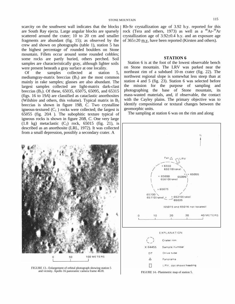
FIGURE 13.- Enlargement of orbital photograph showing station 5 and vicinity. Apollo 16 panoramic camera frame 4618. FIGURE 14.- Planimetric map of station 5.
115 STONE MOUNTAIN
scarcity on the southwest wall indicates that the blocks are South Ray ejecta. Large angular blocks are sparsely scattered around the crater; 10 to 20 cm and smaller fragments are abundant (fig. 15); as observed by the crew and shown on photographs (table 1), station 5 has the highest percentage of' rounded boulders on Stone mountain. Fillets occur around some rounded cobbles; some rocks are partly buried, others perched. Soil samples are characteristically gray, although lighter soils were present beneath a gray surface at one locality.
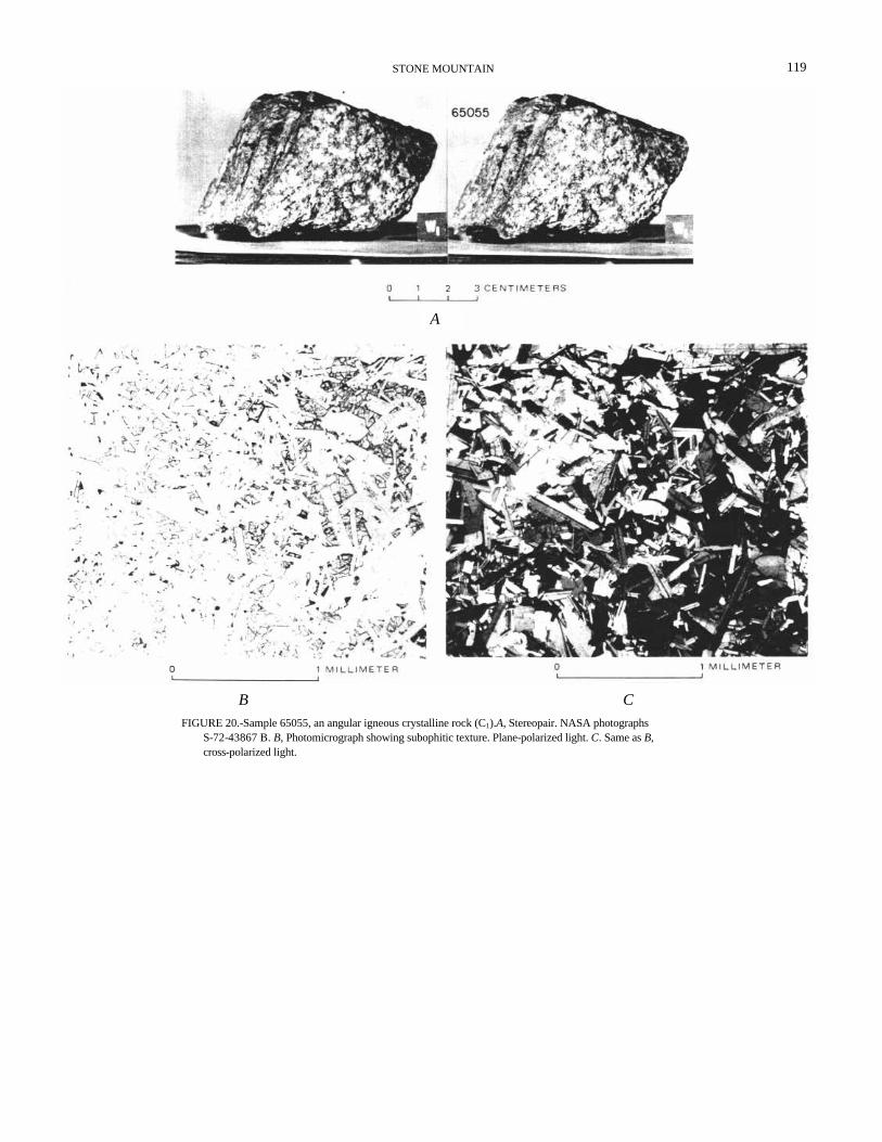
Of the samples collected at station 5, mediumgray-matrix breccias (B3) are the most common mainly in rake samples; glasses are also abundant. The largest samples collected are light-matrix dark-clast breccias (B2). Of these, 65035, 65075, 65095, and 65315 (figs. 16 to 19A) are classified as cataclastic anorthosites (Wilshire and others, this volume). Typical matrix in B2 breccias is shown in figure 19B, C. Two crystalline igneous-textured (C1 ) rocks were collected; the largest is 65055 (fig. 20A ). The subophitic texture typical of igneous rocks is shown in figure 20B, C. One very large (1.8 kg) metaclastic (C2) rock, 65015 (fig. 21), is described as an anorthosite (LRL, 1972). It was collected from a small depression, possibly a secondary crater. A
Rb-Sr crystallization age of 3.92 b.y. reported for this rock (Tera and others, 1973) as well as a 40Ar-39Ar crystallization age of 3.92±0.4 b.y. and an exposure age of 365±20 m.y. have been reported (Kirsten and others).
STATION 6 Station 6 is at the foot of the lowest observable bench
on Stone mountain. The LRV was parked near the northeast rim of a subdued 10-m crater (fig. 22). The northwest regional slope is somewhat less steep than at station 4 and 5 (fig. 23). Station 6 was selected before the mission for the purpose of sampling and photographing the base of Stone mountain, its mass-wasted materials, and, if observable, the contact with the Cayley plains. The primary objective was to identify compositional or textural changes between the geomorphic units.
The sampling at station 6 was on the rim and along

FIGURE 16.-Stereopair of sample 65035 a light-matrix dark-clast (B2) breccia (NASA photo graphs S-72--42057-42057B).
FIGURE 15.-Rock distribution within 10 m of site of station 5 panorama. See figure 12 for explanation of symbols.
GEOLOGY OF THE APOLLO 16 AREA, CENTRAL LUNAR HIGHLANDS 116

STONE MOUNTAIN 117
FIGURE 17.-Sample 65075, a highly fractured light-matrix darkclast (B2) breccia (NASA photograph S-72-39412).
FIGURE 18. -Stereopair of sample 65095, a glass-coated light-matrix dark-clast (B2) breccia. NASA photographs S-72- 40975-40975B.

GEOLOGY OF THE APOLLO 16 AREA, CENTRAL LUNAR HIGHLANDS 118
FIGURE 19.- Sample 65315, a light-matrix dark-clast (B2) breccia displaying a partly glass-coated surface. A, Stereopair. NASA photographs S-72-42103-42103B. B, Photomicrograph of a crushed feldspar matrix in 65315, typical of cataclastic anorthosites, Plane polarized light. C, Same as B, cross-polarized light.
B C
A
STONE MOUNTAIN 119
FIGURE 20.-Sample 65055, an angular igneous crystalline rock (C1).A, Stereopair. NASA photographs S-72-43867 B. B, Photomicrograph showing subophitic texture. Plane-polarized light. C. Same as B, cross-polarized light.
A
B C

FIGURE 22.-Station 6 and vicinity. Apollo 16 panoramic camera frame 4618.
FIGURE 21.-Stereopair of sample 65015, a metaclastic rock (C2). NASA photographs S- 72-39209- 39209B.
GEOLOGY OF THE APOLLO 16 AREA, CENTRAL LUNAR HIGHLANDS 120

STONE MOUNTAIN 121
FIGURE 23.-Topographic map of the Stone mountain area showing stations 4, 5, and 6 and geologic contact from Hodges (this volume, pl. 1). Photogrammetry by G. M. Nakata.

GEOLOGY OF THE APOLLO 16 AREA, CENTRAL LUNAR HIGHLANDS 122
< FIGURE 25.-Rock distribution within 10 m of site of station 6 panorama. See figure 12 for explanation of symbols.
DISCUSSION AND SUMMARY Stations 4 and 5 on the north slope of Ston mountain
were selected as the prime localities for Descartes mountains materials. Chemical analyses and petrographic characteristics of the samples collected on Stone mountain do not differ significantly from those of
the west wall of the crater where the LRV was parked (pl. 6, pan 12; fig. 24). The surface is covered by numerous small shallow craters; only a few are as large as 10 m. Angular blocks to 0.5 m are scattered throughout the area; 10- to 20-cm fragments are most common, covering about 1 percent of the surface, (fig. 25, table 1). As shown on plate 6, pan 12, the rock distribution within the subdued 10-m crater at the LRV appears: asymmetric; rocks are sparse on the southwest wall, which was probably shielded from South Ray crater ejecta.
The rocks described and photographed exhibit a wide variety of shapes and sizes. Angular glass-coated blocks are scattered over much of the surface. Small white clasts common in many of these rocks indicate that breccias predominate. Fillets are moderately developed around some rocks. Several rocks appear to be partly buried; others appear perched, suggesting that they were transported to their present location as ejecta from South Ray crater.
One white "splotch" of indurated soil, 66080, was collected from the southwest wall of the crater; the reg- olith elsewhere was apparently gray throughout.
Only four large rock samples were collected at station tion 6; all have been classified as breccias by Wilshire and others (this volume). Samples 66075 and 66035 (figs. 26 and 27A) are classified as intermediate-gray matrix breccias (B3), with approximately aqual amounts of dark and light clasts. As shown in figure 27B, 66035 has cataclastic texture. Sample 66055 (fig 28) is a light-matrix dark-clast breccia (B2), described as a cataclastic anorthosite by Wilshire and othe (this volume). Sample 66095 (fig. 29A) is a dark-matri light-clast breccia (B4). It weighs more than a kilogra and is highly fractured. The rock has been called "rusty rock" and was the first discovered to contain significant amount of hydrated iron oxide believed be of lunar origin (Nunes and Tatsumoto, 1973; Fried man and others, 1974). It can be described as an anorthositic breccia (LRL, 1972) with a locally recrystallized matrix (fig. 29B, C). 40Ar_39Ar data suggest that this rock was partly recrystallized by an impact even around 3.6 b.y. ago (Turner and others, 1973, p. 1899)

FIGURE 26.-Sample 66075, a well-indurated B3 breccia. NASA photograph S-72-37203.
samples from the Cayley plains. As ray materials from South Ray crater occupy much of the landing site, it is possible that underlying Descartes bedrock may not have been sampled. Alternatively, both plains and highlands at this site may be accumulations of similar breccias. Detailed comparisons of soils and rocks from stations 5 and 6, which lie on opposite sides of the apparent Cayley-Descartes contact, indicate no major chemical differences between the two sample suites. If the materials that formed the Descartes mountains were indeed sampled, then whatever differences exist between the two formations must be expressed by properties other than chemical composition and petrography. The greater abundance of angular blocks of the 20- to 5-cm size fraction at station 4 can be attributed to a relatively heavy concentration of large blocks of ray material there.
From a review of surface evidence (station panorama photographs, Hasselblad 70-mm, and 16-mm photographs), it appears that station 4 may be located on the edge of a minor ray from South Ray crater. From orbit, however, no rays are visible near the station 4 location. Additional evidence for South Ray ejecta is the large asymmetric boulder field of fresh angular blocks
observed at station 4. Of the three stations, station 5 has the greatest percentage of rounded boulders on the surface and appears to be contaminated by few angular blocks of South Ray ejecta. Station 6 appears to be located on the edge of a ray from South Ray crater (Freeman, this volume, fig. 1), although no large block fields are visible. As station 6 is at the base of Stone mountain, Descartes materials may have accumulated by mass wasting from the mountain and may be quite thick (see Freeman, this volume). Boulder fields possibly representing South Ray ejecta were identified on 16-mm photographs along the traverse route (fig. 30). Both stations 4 and 6 fall within boulder fields; station 5 does not, although it is near one.
Whether the materials making up the Descartes mountains were actually sampled remains undetermined. Stations 4 and 6 appear to be contaminated by Cayley materials ejected from South Ray crater, although the larger (25+ g) samples collected at station 4a are possibly Cinco a ejecta from beneath the regolith. Station 5, which appears to be free of South Ray ejecta, may be the most promising locality from which Stone mountain material may eventually be identified in the sample collection.
STONE MOUNTAIN 123

FIGURE 28.- Sample 66055 (stereopair), a light-matrix dark-clast (B2) breccia.
NASA photographs S-72-42722-42722b.
FIGURE 27.- Sample 66035, a coherent B3, breccia. A. Stereopair NASA photographs S-72-41300-41300B. B, Photomicrograph showing cataclastic texture. Plane-polarized light.
GEOLOGY OF THE APOLLO 16 AREA, CENTRAL LUNAR HIGHLANDS 124
B
A

STONE MOUNTAIN 125
FIGURE 29.-Sample 66095, "rusty rock," a highly fractured dark-matrix light-clast B4 breccia. A, Stereopair. NASA photographs S-72-41436-41436B. B, Photomicrograph showing ophitic matrix and interstitial opaque minerals that are partly oxidized. C, Same as B, cross-polarized light.
B C
B

GE0LOGY OF THE APOLLO 16 AREA, CENTRAL LUNAR HIGHLANDS 126
FIGURE 30.-Boulder fields, possibly South Ray ejecta, identified on 16-mm traverse photographs.