D34 Troubleshooting Guide EN final - European Commission · Inspection of Module and Array...
20
www.pvtrin.eu PVTRIN Training course TROUBLESHOOTING GUIDE Martifer Solar SA
Transcript of D34 Troubleshooting Guide EN final - European Commission · Inspection of Module and Array...
www.pvtrin.eu
PVTRIN Training course
TROUBLESHOOTING GUIDE
Martifer Solar SA


PVTRIN Training course - Troubleshooting Guide iii
CONTENTS
CONTENTS iii
SUMMARY iv
1. COMMON MISTAKES AND FAILURES 1
1.1. Introduction 1
1.1.1. Insulation failures 1
1.1.2. Inverter failures 1
1.1.3. Construction failures 1
1.2. Common mistakes 1
1.3. Troubleshooting 3
2. DIAGNOSTIC PROCEDURES 7
2.1. Visual inspection procedures 7
2.1.1. Array Inspection 7
2.1.2. Wire Inspection 7
2.1.3. Inverter Inspection 7
2.1.4. Inspection of Module and Array
Grounding 8
2.2. Performance monitoring 8
2.2.1. User feedback 8
2.2.2. Performance verification 8
2.2.3. Displays 8
2.2.4. Design Software 9
2.2.5. Data Acquisition Systems 9
2.2.6. Sensors 9
2.3. Calibration and Recalibration 10
2.4. Data Storage and Transmission 10
2.4.1. Data Analysis 10
ANNEX 11
INDICATIVE REFERENCES 13
ACKNOWLEDGEMENTS 15
PVTRIN PARTNERS 16
Soitec

PVTRIN Training course - Troubleshooting Guide iv
SUMMARY
The PVTRIN troubleshooting guide aims to present the actions should be taken in order to
ensure a proper performance of a PV system. The maintenance and troubleshooting
requirements are -in many cases- the same for stand-alone and grid connected PV systems,
however it may be different depending on the circumastances.
This document deals with operational issues that can reduce the performance of the PV
systems and provides the necessary documentation for operating and maintenance
procedures to minimise those losses.
The Guide is not intended to be either exhaustive or definitive and cannot guarantee to cover all possible
situations in depth. Technicians are advised to exercise their own professional judgment and to consult
all current building regulations, health and safety codes, standards and other applicable guidelines, as
well as the technical manual of the equipment used.

PVTRIN Training course - Troubleshooting Guide 1
1 COMMON MISTAKES
AND FAILURES
1. COMMON MISTAKES AND
FAILURES
1.1. Introduction
As PV systems have now been in operation
for many years, a store of useful information
has been accumulated on their typical faults
and problems.
1.1.1. Insulation failures
Over recent years, the quality of module
connections has significantly improved since
the widespread introduction of plug
connectors. The use of cable ties or wiring
that is not UV or temperature resistant has
proven highly problematic. Insulation also
needs to withstand mechanical loads. All
insulation ages over the course of time. For
electrical power supplies, the physical
operating life of power cables is generally
specified as 45 years. Insulation can also be
damaged by UV radiation, excessive voltage
and mechanically. Suitable protection for
cables is readily available on the market. Any
insulation fault – whatever the cause - on the
DC side can result in arcing, which is a serious
fire risk. In consequence, all wiring should be
periodically checked for any mechanical or
thermal damage. The best way to do this is to
measure the insulation resistance.
Automatic insulation monitoring, as
performed by many inverters, is therefore a
very useful feature. It signals an insulation
fault and the inverter then isolates the
system from the grid. However, the
illuminated PV array will still supply direct
current to feed the arc. Consequently the
fault cannot be isolated by the inverter. If an
insulation fault is indicated, the cause of the
fault should be traced as quickly as possible.
In a system with one or two strings, wiring
faults can be detected by checking the
inverter.
1.1.2. Inverter failures
The most frequently reported faults
according to a great many studies are
inverter faults (63%). However, there have
been considerable improvements in this
sector over time. A common fault is incorrect
dimensioning and/or incorrect cable or
voltage matching with the PV array. Most PV
installation firms have now overcome this
problem, and simulation software programs
and design tools from inverter manufacturers
also provide support in this area. Other
sources of inverter trouble are voltage surge
effects caused by electrical storms or grid
switching, ageing and thermal overload.
Further failures are simply due to device
faults (DGS, 2008).
1.1.3. Construction failures
A common failure regarding PV mounting
systems is the distortion of the PV modules
when they are installed on the roof, in order
to form a flat array surface mechanically.
Under the influence of temperature and
wind, or over the course of time, the module
glass may shatter. Typical faults in PV
mounting systems are an absence of
expansion joints between modules or too few
roof hooks to take account of the wind load.
Moreover, the wrong choice of materials can
cause corrosion on the mounting frame and
compatible materials should be used at all
times (DGS, 2008).
1.2. Common mistakes
Mistakes in a PV installation can be
minimized, by ensuring appropriate design,
installation and maintenance. Usually, most
mistakes occur in PV installations during
installation. In this sub-section, the most
frequent installation mistakes are listed
(Brooks Engineering, 2010).

PVTRIN Training course - Troubleshooting Guide 2
Common Installation Mistakes with Array
Modules and Configurations:
• Changing the array wiring layout without
changing the submitted electrical diagram.
• Changing the module type or
manufacturer as a result of supply issues.
• Exceeding the inverter or module voltage
due to improper array design.
• Putting too few modules in series for
proper operation of the inverter during
high summer array temperatures.
• Installing PV modules without taking
account of the Impp of each module
(grouping).
Common Installation Mistakes with Wire
Management:
• Human mistakes regarding the wire
connection during installation.
• Not enough supports to secure the cable
properly.
• Conductors touching roof or other
abrasive surfaces exposing them to
physical damage.
• Not supporting raceways at proper
intervals.
• Multiple cables entering a single
conductor cable gland
• Not following support members with
conductors.
• Pulling cable ties too tight or leaving them
too loose.
• Not fully engaging plug connectors.
• Bending conductors too close to
connectors.
• Plug connectors on non-locking
connectors not fully engaged
Common Installation Mistakes with Module
and Array Grounding:
• Not installing a grounding conductor on
the array at all.
• Not connecting the different parts of the
modules together to achieve equal
potential grounding
• Using indoor-rated grounding lugs on PV
modules and support structures.
• Assuming that simply bolting aluminium
frames to support structures provides
effective grounding.
• Installing an undersized conductor for
grounding
• Not installing lightning protection properly
Common Installation Mistakes with
Electrical Boxes, Conduit Bodies, and
Disconnecting Means:
• Installing disconnects rated for vertical
installation in a non-vertical application.
• Installing incorrectly rated fuses in source
combiners and fused disconnects.
• Covering boxes or conduit bodies leaving
them almost inaccessible for service.
• Not following manufacturer’s instructions
for wiring disconnect on the DC side.
• Installing dry wire nuts in wet locations
and inside boxes that routinely get wet.
• Using improper fittings to bring
conductors into exterior boxes.
Common Installation Mistakes with
Mounting Systems:
• Not using supplied or specified hardware
with the mounting systems.
• Not installing flashings properly.
• Not using the correct roof adhesives for
the specific type of roof.
• Not attaching proper lag screws to roofing
members.
• Not drilling proper pilot holes for lag
screws and missing or splitting roofing
members.

PVTRIN Training course - Troubleshooting Guide 3
1 COMMON MISTAKES
AND FAILURES
1.3. Troubleshooting
The fault correction method depends upon
the type of fault and the type of PV system.
First, customers should be asked when and
how the fault came to their attention. Circuit
diagrams and a technical description of the
system are very helpful. Before taking
measurements, a visual check of the PV
system should be carried out – in particular,
of the PV array – to check for mechanical
damage and soiling. Wiring and electrical
connections should also be checked.
The measurements required to find faults in
grid-connected systems are essentially the
same as those required for commissioning.
Today, increasingly, remote diagnostics via a
modem and PC are also possible with more
modern inverters.
The step-by-step troubleshooting procedure
is described in the following paragraphs:
Step 1: Inverter and PV combiner/junction
box
Firstly, the measurement check of the
inverter and the PV combiner/junction box
should start with the respective connecting
wires. Test the inverter operating data, by
checking the LED or error code, or by using
remote software and a laptop. The inverter's
operating data records can give useful
information for the localization of the faults.
For the measurement check, test the AC side
and then the DC side at the inverter. Then,
check the DC cable and the DC main
disconnect/isolator switch. When measuring
the insulation resistance, the resistance to
the ground potential should be at least
2MOhm.
Step 2: Ground and short-circuit faults
Ground and short-circuit faults can be
detected by following the troubleshooting
procedure, but the PV strings should first be
separated and measured individually. To do
this, first switch off the inverter and, if
present, switch off the DC switch or DC
switches. Then one module per string should
be completely darkened by covering it from
sunlight. Now the strings can be separated
without the danger of arcing and
measurement can begin.
Step 3: String fuses/diodes/modules
The voltage at the string fuses and diodes can
be measured during operation by using a
voltmeter in parallel. If excessive differences
are present in the individual string voltages
and/or string short-circuit currents, this is
either an indication of excessively high
mismatching in the generator or an indication
of an electrical fault in one or more strings. It
may therefore be necessary to take individual
measurements at the modules of the
corresponding string. For longer strings,
divide the string in half and find out which is
the faulty half of the string. Then, use the
same method on the faulty half of the string
to identify the faulty module. The module
connections and bypass diodes should also be
tested.
Step 4 Open-circuit voltage and short-circuit
current
Measurement of the open-circuit voltage and
the short-circuit current is very important for
monitoring the operation of the system but
the current irradiance of the area should also
be recorded.
Some typical failures which are encountered
in PV installations are listed in TABLE 1 below.
On the right side column the possible reasons
for these failures are reported alongside
corrective measures in order to troubleshoot
the problem and put the system back in
operation (DGS, 2008).
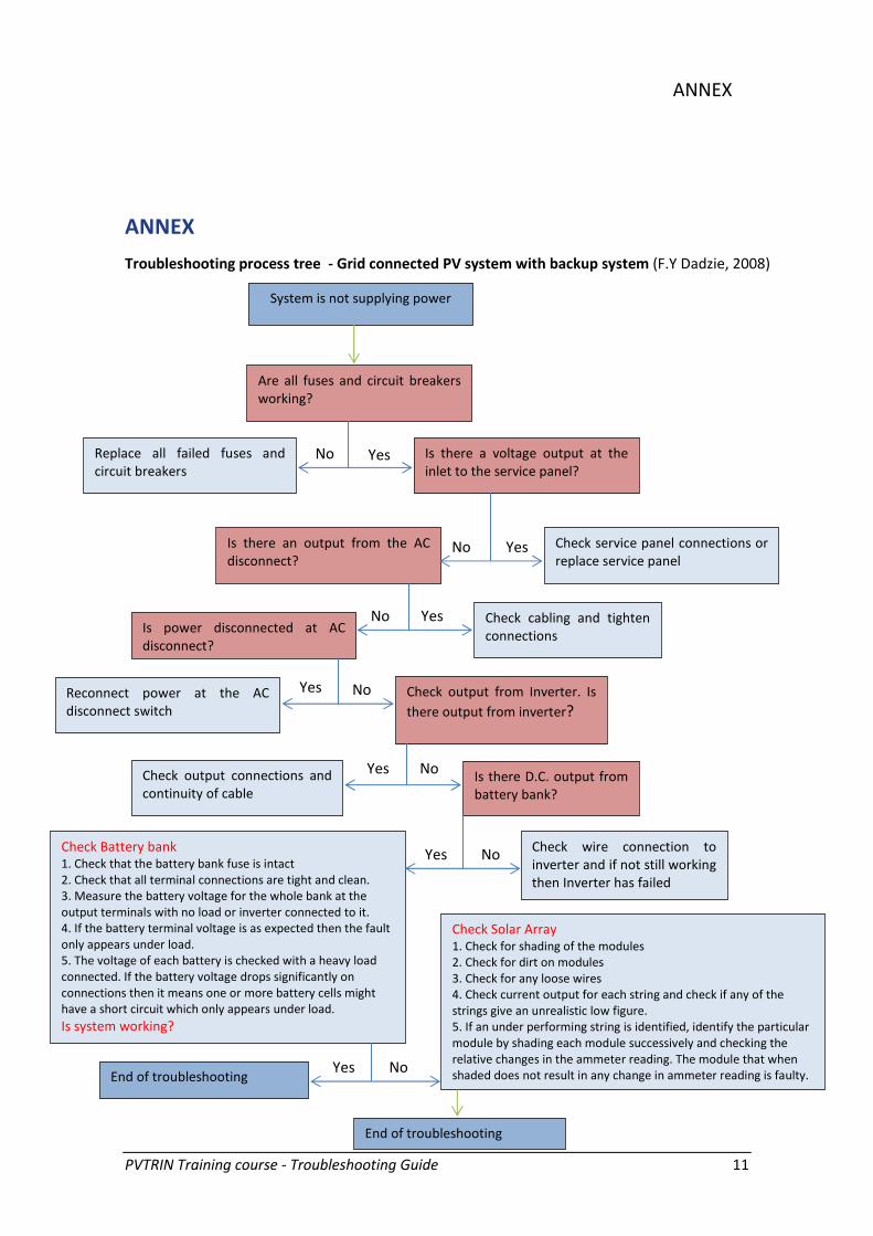
In the Annex, a troubleshooting tree (F.Y
Dadzie, 2008) is presented regarding a grid
connected PV system with backup system.

PVTRIN Training course - Troubleshooting Guide 4
TABLE 1. TYPICAL FAILURES AND CORRECTIVE MEASURES AND TROUBLESHOOTING. (Principal source: Karamchetti M, 2011)
Typical failures Corrective measures and troubleshooting
Failure in any PV system
component
Try to get as much information from the customer as possible
Get as much information, such as prints, outputs and wiring diagrams, as possible
Follow the manufacturer’s instructions regarding malfunction
Entire PV system is down Prior to getting on the roof, check and record the inverter’s input voltage and current level from the array
No current from array Switches, fuses, or circuit breakers open, blown, tripped, wiring broken or corroded
Array current is low Cloudy conditions, a defective blocking or bypass diode, a damaged module, one or more parallel connection between
modules in the string is broken, loose, or dirty. Replace a damaged module or one with internal parallel connection
problems. Replace defective diodes and clean and tighten all connections. Some of the array may be shaded, significantly
reducing the array’s current output. Remove the shade source to regain the string’s full current output.
Dirty modules also could cause reduced current output. Wash the modules to restore the array’s current output.
Output voltage is low Some modules in the series string are defective or disconnected and need to be replaced. Defective blocking or bypass
diodes in the modules may need to be replaced. Low voltage also could be caused by the wrong wiring connecting the
modules in the string to the junction box or combiner box or the inverter. The wiring could be either sized too small or the
wire run is too long for the string’s output current level. Upgrading the wire size for the current level should correct this
problem.
Battery is not charging
(aytonomous systems)
Measure PV array open circuit voltage and confirm it is within normal limits. If voltage is low or zero, check the connections
at the PV array itself. Disconnect the PV from the controller when working on the PV system. Measure PV voltage and
battery voltage at charge controller terminals if voltage at the terminals is the same the PV array is charging the battery. If
PV voltage is close to open circuit voltage of the panels and the battery voltage is low, the controller is not charging the
batteries and may be damaged.
Battery is always at a low
state of charge
(autonomous systems)
Reduce load size or increase system size. (Sandia National Laboratories, 1991)
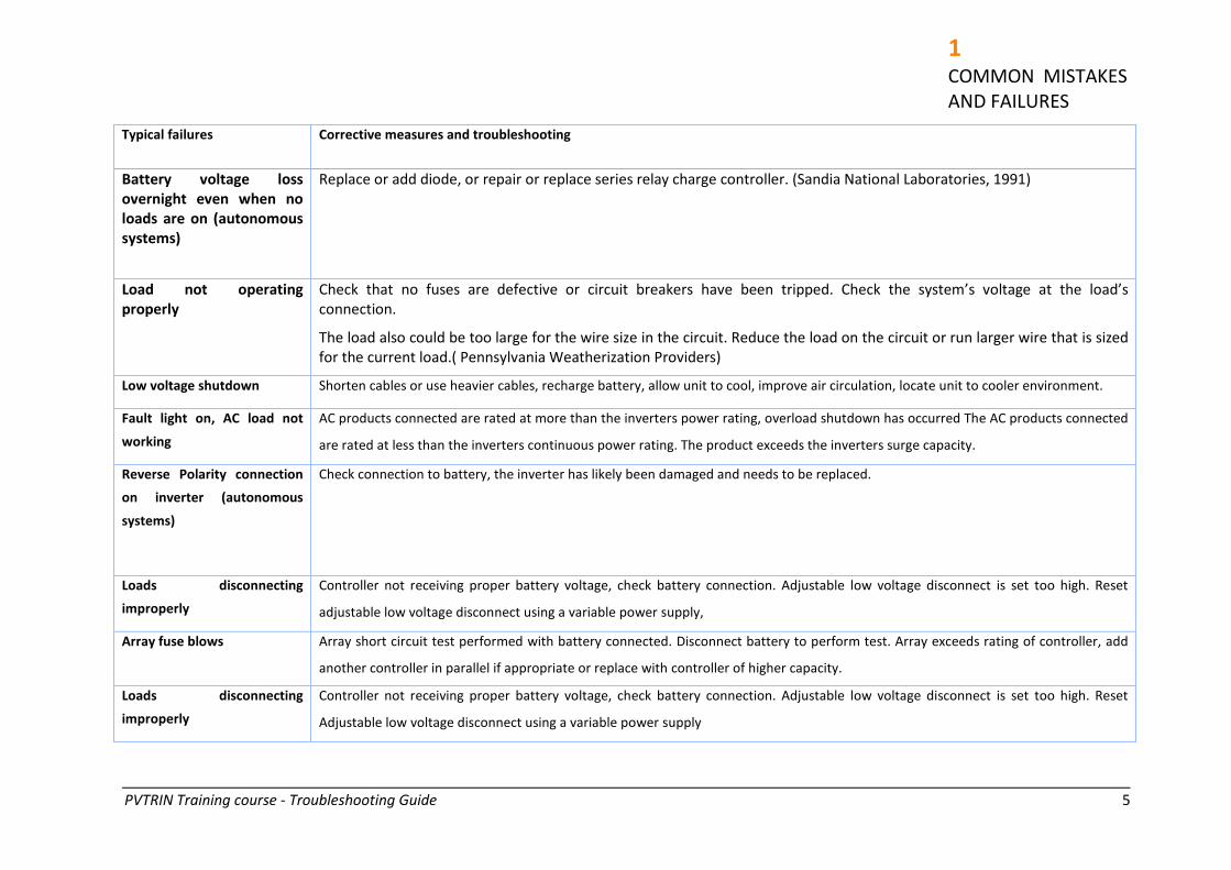
PVTRIN Training course - Troubleshooting Guide 5
1 COMMON MISTAKES
AND FAILURES
Typical failures Corrective measures and troubleshooting
Battery voltage loss
overnight even when no
loads are on (autonomous
systems)
Replace or add diode, or repair or replace series relay charge controller. (Sandia National Laboratories, 1991)
Load not operating
properly
Check that no fuses are defective or circuit breakers have been tripped. Check the system’s voltage at the load’s
connection.
The load also could be too large for the wire size in the circuit. Reduce the load on the circuit or run larger wire that is sized
for the current load.( Pennsylvania Weatherization Providers)
Low voltage shutdown Shorten cables or use heavier cables, recharge battery, allow unit to cool, improve air circulation, locate unit to cooler environment.
Fault light on, AC load not
working
AC products connected are rated at more than the inverters power rating, overload shutdown has occurred The AC products connected
are rated at less than the inverters continuous power rating. The product exceeds the inverters surge capacity.
Reverse Polarity connection
on inverter (autonomous
systems)
Check connection to battery, the inverter has likely been damaged and needs to be replaced.
Loads disconnecting
improperly
Controller not receiving proper battery voltage, check battery connection. Adjustable low voltage disconnect is set too high. Reset
adjustable low voltage disconnect using a variable power supply,
Array fuse blows Array short circuit test performed with battery connected. Disconnect battery to perform test. Array exceeds rating of controller, add
another controller in parallel if appropriate or replace with controller of higher capacity.
Loads disconnecting
improperly
Controller not receiving proper battery voltage, check battery connection. Adjustable low voltage disconnect is set too high. Reset
Adjustable low voltage disconnect using a variable power supply
PVTRIN Training course - Troubleshooting Guide 6
Typical failures Corrective measures and troubleshooting
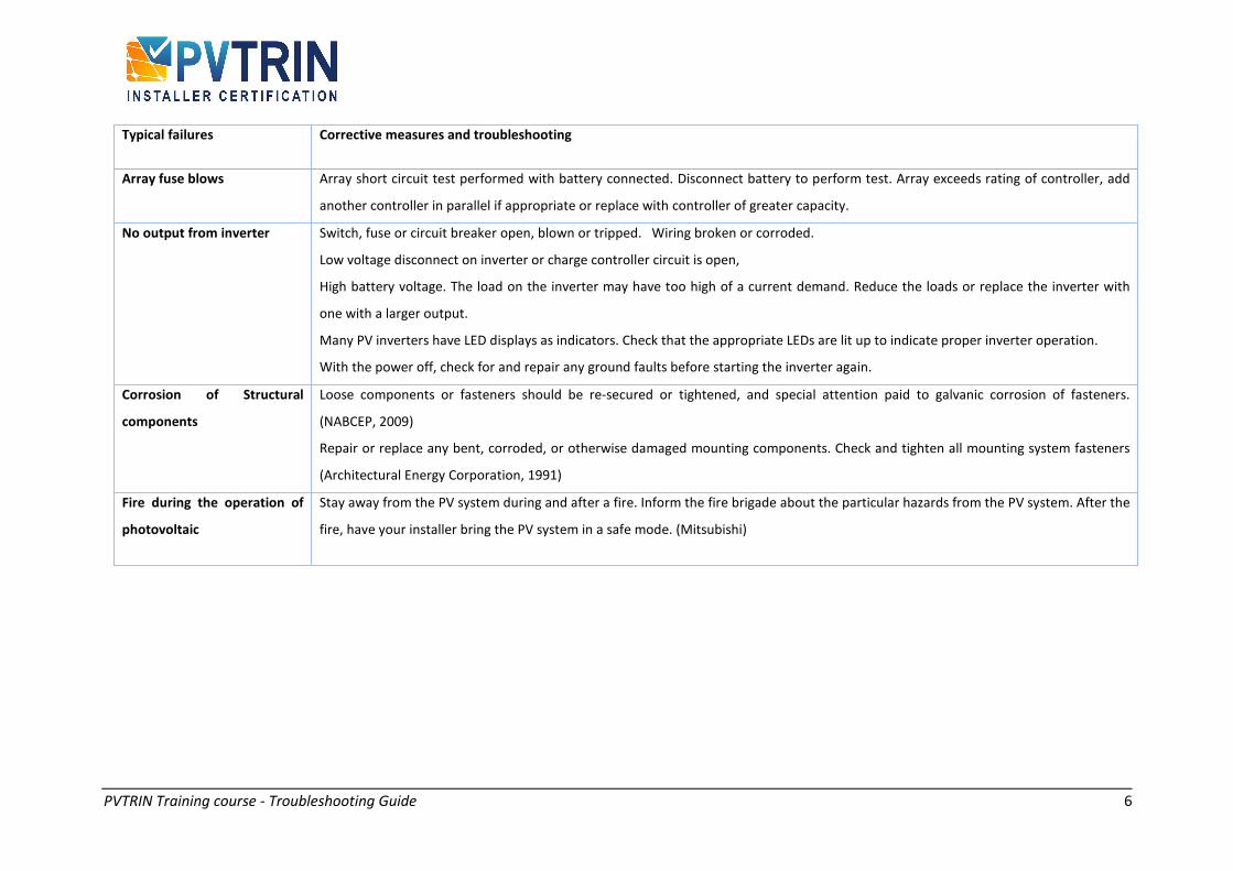
Array fuse blows Array short circuit test performed with battery connected. Disconnect battery to perform test. Array exceeds rating of controller, add
another controller in parallel if appropriate or replace with controller of greater capacity.
No output from inverter Switch, fuse or circuit breaker open, blown or tripped. Wiring broken or corroded.
Low voltage disconnect on inverter or charge controller circuit is open,
High battery voltage. The load on the inverter may have too high of a current demand. Reduce the loads or replace the inverter with
one with a larger output.
Many PV inverters have LED displays as indicators. Check that the appropriate LEDs are lit up to indicate proper inverter operation.
With the power off, check for and repair any ground faults before starting the inverter again.
Corrosion of Structural
components
Loose components or fasteners should be re-secured or tightened, and special attention paid to galvanic corrosion of fasteners.
(NABCEP, 2009)
Repair or replace any bent, corroded, or otherwise damaged mounting components. Check and tighten all mounting system fasteners
(Architectural Energy Corporation, 1991)
Fire during the operation of
photovoltaic
Stay away from the PV system during and after a fire. Inform the fire brigade about the particular hazards from the PV system. After the
fire, have your installer bring the PV system in a safe mode. (Mitsubishi)

PVTRIN Training course - Troubleshooting Guide 7
2 DIAGNOSTIC
PROCEDURES
2. DIAGNOSTIC PROCEDURES
2.1. Visual inspection procedures
The mechanical problems are generally
evident by something being loose or bent or
broken or corroded, can generally be found
with a visual check. To perform an inspection
the weather should be good and all
inspections must completed through a clear,
sunny day. (Rudkin E. & Thornycroft J., 2008)
2.1.1. Array Inspection
The PV array is the first item that needs
inspection as PV arrays can influence the
performance of the PV system. This can be a
difficult procedure if the array is placed on
multiple roof faces of the building and the
visual inspection of the array cannot be
carried out. Sometimes, the array inspection
cannot take place as the inspector is unable
to get on the roof. In such situations using a
lift or a secured ladder at the time of
inspection is recommended.
Once the inspector has either gained access
to the roof or has a clear view of the roof, the
number of PV modules of the system must be
counted. It is important that the number of
modules matches that of the plans and a
comparison should take place.
At the back of the modules, there is a label
listing all the characteristics of the PV
module. During the visual inspection, the
label should be checked so as to confirm the
model number of a module. A photo of the
label is a good option if there is a difficulty to
view the back side. Otherwise, if possible the
module should be moved, so as the
inspection is completed successfully.
Also, an inspection should include a check of
the physical condition of the photovoltaic
array as some can become distorted or
settled under stress. This may crack the glass
on the front and the module must be
replaced. Futhermore, under temperature
and wind influences, the PV modules may
shatter. Additionally, an inspector may check
for any signs of corrosion on the mounting
frame. This can appear due to the wrong
choice of material. Poor system conditions
may lead to losses in output power.
(DTI,2006)
(The German Energy Society, 2008)
(Brooks Engineering, 2010)
(Rudkin E. & Thornycroft J., 2008)
2.1.2. Wire Inspection
The inspector must get near the PV array and
inspect under the modules array. Conductors
must not lie on the roof or come in contact
with sharp surfaces that may cause them
physical damage. Also the inspector should
check if the connectors are fully engaged. The
wiring should be checked often for any
mechanical and termal damage. A simple way
of doing this is to measure the insulation
resistance. Attention should be taken to
minimise cable lengths, and to ensure that all
connections are made in the correct way and
are protected. A poor connection may reduce
the performance of the system in the long
term. It is better to ensure the quality of the
connections during the installation. This can
save time at the inspection, as the inspector
will not have to identity and localize the poor
connections.
(DTI,2006)he German Energy Society,
2008)
(Brooks Engineering, 2010)
2.1.3. Inverter Inspection
Output reductions are observed when the
inverter shows operational problems. The
inverter may shut down, present a fault, or
failed to restart automatically due to a grid
fault. Faults with inverters may not be
noticed for a long period of time. So, it is

PVTRIN Training course - Troubleshooting Guide 8
important to check system operation. A
display can be used. This should be placed in
a visible and accessible position where the
user can find out and diagnose when the
system is operating. In addition to this, the
display may have an indication light that
shows when the inverter is on and operates
correctly. (DTI,2006)
2.1.4. Inspection of Module and Array
Grounding
PV module and array grounding is one of the
most important safety issues in a PV
installation. For module grounding, an
electrical connection is created between the
module frame and the equipment grounding
conductor. This connection requires all the
modules array to have additional array
grounding which is important for lightning
and surge grounding. (Brooks Engineering,
2010)
2.2. Performance monitoring
2.2.1. User feedback
User feedback is one of the most important
factors for ensuring good performance and
operation of the PV system. Users can check
the inverter operation, output power levels,
shading problems or obvious damage to the
system. This can range from a simple LED on
the inverter lid or a user display in a domestic
corridor, to a large interactive wall display in
the entrance hall of a corporate building. All
displays provide the users an indication that
the system is functioning. A clear display
gives much added value to the system,
especially if combined with some graphic or
text explaining the concepts. When a
problem occurs, the users may call the
specialists to resolve and fix the problem. Is
important that the user understands how to
make the necessary checks- the system
installer is responsible to provide this
information to the user. (DTI,2006)
2.2.2. Performance verification
A system may have been financed on the
basis of its output through support schemes
(Feed-in Tariffs), and so the user is good to
measure the output and compare to the
claims for the system. The complexity and
expense of such metering is determined by
the number and accuracy of the
measurements to be made. A display is the
interface between the user and the system
and is the main source of information on the
system performance. (DTI,2006)
FIGURE 1.
MEASUREMENTS ON A ROOF GRID CONNECTED PV SYSTEM
(Source: Conercon Ltd)
2.2.3. Displays
Displays are the backbone of monitoring.
With a display unit, the user is able to see the
output power of the PV system. Some
displays, may also include information on the
consumption of the building, giving an
estimate of the amount of electricity
generated. The displayed values must be
clear, easily understood and accessed. If the
display is to be effective it must be in a place
where it is visible and accessible in everyday
activities. In some cases, displays were

PVTRIN Training course - Troubleshooting Guide 9
2 DIAGNOSTIC
PROCEDURES
installed in an open area (hallway), but either
too high or too low to be easily viewed, thus
difficult to read. It is also not recommended
to place displays inside the meter cupboard,
as they are not readily viewed.
Other kind of displays are remote displays
which are easier to site, and may be provided
with data from the inverter itself, or by a
meter in the cabling from inverter to
distribution board. A significant cost to
installing this is the routing of the cabling to
the display, but there are instruments on the
market that avoid this by utilizing short-range
radio transmission.
The easiest to fit is a simple indication as part
of the inverter. Most PV inverter
manufacturers offer an optional display.
However this can place severe constraints on
the placing of the inverter, which would
normally be in a roof void, electrical switch
room, or some other secluded place.
If the display is to be effective it must be in a
place where it is visible in everyday activities.
Remote displays are easier to site, and may
be provided with data from the inverter itself,
or by a meter in the cabling from inverter to
distribution board. A significant cost to
installing this is the routing of the cabling to
the display, but there are instruments on the
market that avoid this by utilizing short-range
radio transmission.
There are many different formats of data that
can be displayed: the most popular are the
instantaneous power being generated, and
the total energy to date. However, large
displays often include derived values that
mean more to the public, such as numbers of
lights that are being powered, or the amount
of carbon production being offset. A
computer-based monitoring system can often
embed that information within a touch
screen driven information point, or to have it
displayed on the website for the building.
(DTI,2006)
2.2.4. Design Software
All system design programmes have
assumptions embedded in program
calculations. Therefore, the accuracy of the
output depends on the accuracy of those
assumptions that are appropriate for the case
being considered.
The software is designed to be general. The
user can modify the values of a number of
operating parameters and built the software
with the desired parameters.
Most of software packages have imported
data from packages and provide
meteorological information for many sites
around the world. System designers should
select a data site that is climatically matched
to the installation site with similar latitude. (DTI,2006)
2.2.5. Data Acquisition Systems
The main system tends to fall into two types:
loggers and computers. The advantage of a
logger is its simplicity and robust
construction, but its disadvantage is its
inflexibility and cost. A computer system, in
contrast, may be slower to set up and
commission, but has the advantage of a
wider choice of operational modes and
custom settings, while the cost may be less
for a system based on a desktop PC. The
choice between the types may well be
dictated by the type of monitoring strategy.
2.2.6. Sensors
There is no limit to the inputs that may be
monitored for a PV System, but most systems
will need to measure input and output
energy, and some environmental and system
variables.

PVTRIN Training course - Troubleshooting Guide 10
2.3. Calibration and Recalibration
The system should be set up and calibrated
preferably in situ. The need for recalibration
should be determined whilst considering the
length of time for the monitoring, and the
accuracy required of the system. The
reference cell is particularly critical, but often
the most difficult item to access. If annual
recalibration is not practical back in the
laboratory, an on-site comparison with a
reference device nearby may be adequate.
The entire monitoring system can also benefit
from a comparative calibration using hand-
held reference devices (ambient temperature
sensors, voltage and current meters, etc.).
2.4. Data Storage and
Transmission
The data is generally stored in situ using RAM
for a logger, or using a hard drive for a
computer system. Loggers often include
removable RAM cards, discs, or other
magnetic media, as a form of
storage/retrieval. PCs may use multiple
drives, or daily downloads, as a backup
storage method.
Having recorded the data, it may be
transmitted back to the monitoring
organization by many means. The simplest
logging systems may have to be physically
carried back to the laboratory and plugged
into a special reader device, or a PC serial
port.
Removable media allow the swapping of the
storage medium on site allowing monitoring
to continue uninterrupted. The only
disadvantages are that the new media may
not be inserted correctly, or the logger may
not be restarted, and the loss of data will not
be noticed until the next visit. Telephonic
transmission is often used, as it allows
frequent downloading of data (reducing the
length of any 'lost' periods), and also the
chance to 'upload' any changes to the logging
schedule. The more sophisticated loggers can
initiate a call to a fax or PC to report any
faults or out of range signals immediately
they are detected. The advent of the internet
has allowed PCs to connect to a local portal
via a local phone line, thus making
downloading less expensive anywhere in the
world. If a telephone line is not available at a
remote site, a cellular phone connection can
provide an equivalent facility.
2.4.1. Data Analysis
After collecting the PV system data, a
detailed analysis should be conducted. In this
way, the stored data can be a useful tool for
system monitoring and evaluation. Monthly
performance ratio values, array yields, etc.
have become the normal way of defining the
performance of a PV system and continued
use of this method will make it easier to
compare existing systems. Bar graphs can
also be embellished with sub-categories of
capture losses, system losses, etc. For
example, keeping a bar graph record of daily
and monthly energy output is a simple way to
guarantee PV system performance and to
analyze possible system failures (Source:
Rudkin E. & Thornycroft J. 2008). FIGURE 2.
EXAMPLE OF A BAR GRAPH OF A 1KW PV SYSTEM
PVTRIN Training course - Troubleshooting Guide 11
ANNEX
ANNEX
Troubleshooting process tree - Grid connected PV system with backup system (F.Y Dadzie, 2008)
Yes No
System is not supplying power
Are all fuses and circuit breakers
working?
Replace all failed fuses and
circuit breakers
Is there a voltage output at the
inlet to the service panel?
Is there an output from the AC
disconnect?
Check service panel connections or
replace service panel
Is power disconnected at AC
disconnect?
Check cabling and tighten
connections
Reconnect power at the AC
disconnect switch
Check output from Inverter. Is
there output from inverter?
Check output connections and
continuity of cable
Is there D.C. output from
battery bank?
Check Battery bank
1. Check that the battery bank fuse is intact
2. Check that all terminal connections are tight and clean.
3. Measure the battery voltage for the whole bank at the
output terminals with no load or inverter connected to it.
4. If the battery terminal voltage is as expected then the fault
only appears under load.
5. The voltage of each battery is checked with a heavy load
connected. If the battery voltage drops significantly on
connections then it means one or more battery cells might
have a short circuit which only appears under load.
Is system working?
Check wire connection to
inverter and if not still working
then Inverter has failed
End of troubleshooting
Check Solar Array
1. Check for shading of the modules
2. Check for dirt on modules
3. Check for any loose wires
4. Check current output for each string and check if any of the
strings give an unrealistic low figure.
5. If an under performing string is identified, identify the particular
module by shading each module successively and checking the
relative changes in the ammeter reading. The module that when
shaded does not result in any change in ammeter reading is faulty.
End of troubleshooting
No Yes
No Yes
No Yes
Yes No
Yes No
Yes No


PVTRIN Training course - Troubleshooting Guide 13
INDICATIVE REFERENCES
- Architectural Energy Corporation, Maintenance and operation of standalone photovoltaic systems.
December 1991 http://www.scribd.com/doc/2994273/Maintenance-and-Operation-of-
StandAlone-Photovoltaic-Systems
- Black&Decker, Fully automatic battery charger instruction manual
http://www.baccusglobal.com/bd/manuals/BATTERY%20CHARGERS/BCS10B%20MANUAL.pdf
- Brooks Engineering, Field Inspection Guideline for PV systems, June 2010 (Version 1.1)
- Contractors Institute: http://www.contractorsinstitute.com
- DGS, German Energy Society (Deutsche Gesellshaft fur Sonnenenergie), Planning and Installing
Photovoltaic Systems. A guide for installers, architects and engineers second edition, Earthscan,
UK, 2008. Autor:LV Berlin BRB
- DTI, PV domestic field trial good practice guide: Good Practice Guide: Part I Project management
and installation issues (S/P2/00409,URN 06/795 ), 2006.
http://www.bre.co.uk/filelibrary/pdf/rpts/PVDFT_Good_Practice_Guide_Part_1.pdf
- DTI, PV domestic field trial good practice guide, Good Practice Guide: Part II System Performance
Issues (S/P2/00409,URN 06/2219),2006. Autors: Munzinger M, Crick F, Daya EJ., N Pearsall
N.(NPAC), Martin C.(EMC)
http://www.bre.co.uk/filelibrary/pdf/rpts/DFT_GoodPracticeGuidePart2_DTI.pdf
- James P. Dunlop, P.E. Batteries and Charge Control in Stand-Alone Photovoltaic Systems
Fundamentals and Application, January 15, 1997
- Karamchetti J N., Maintenance of Solar Photovoltaic & Renewable Energy Installations.
Presentation, 2011
- Mitsubishi, Transistorized inverter, FR-F500 Instruction manual
http://www.westmillindustries.com/files/F500%20Manual%20Arrow.pdf
- NABCEP (North American Board of Certified Energy Practitioners), NABCEP study guide for
photovoltaic system installers, USA 2009. http://www.nabcep.org/wp-
content/uploads/2008/11/nabcepstudyguidev4-2april2009.pdf
- Pennsylvania Weatherization Providers, Solar Retrofits for Weatherization and Remodels.
http://www.pasolar.ncat.org/lesson08.php
- Rudkin E. & Thornycroft J., Good practice guide “Managing Installation of PV systems” 2008, BERR
- Sandia National Laboratories, Maintenance and operation of stand-alone photovoltaic systems,
December 1991.
- Frank Yeboah Dadzie, Design of a grid connected photovoltaic system for knust and economic and
environmental analysis of the designed system, Department of Electrical/Electronic Engineering,
Kwame Nkrumah University of Science and Technology, 2008
- http://ecmweb.com/contractor/troubleshooting-photovoltaic-systems
Scheuten Solar


PVTRIN Training course - Troubleshooting Guide 15
ACKNOWLEDGEMENTS
This Installers handbook was published within the framework of the PVTRIN project, supported by the Intelligent
Energy - Europe (IEE) programme.
The project steering committee members are:
Dr. Theocharis Tsoutsos (TUC/ENV, GR), Dr. Eduardo Román (TECNALIA, ES), Dave Richardson (BRE, UK), Gaetan
Masson (EPIA, EU-BE), Goran Granić (EIHP, HR), Christos Maxoulis (ETEK, CY), Ing. Camelia Rata (ABMEE, RO),
Antonis Pittaridakis (TEE, GR) and Violetta Groseva (SEC, BU).
The authors and the whole project consortium are deeply grateful to all those who have contributed with their
work in preparing, writing and reviewing this publication. Furthermore, we would like to express our thanks to the
Executive Agency for Competitiveness and Innovation (EACI) for their support.
AUTHORS: Mr. Christos Maxouli and Ms. Anthi Charalambous (ETEK), Ms. Ana Huidobro and Dr. Eduardo Román
(TECNALIA), Dr. Theocharis Tsoutsos, Ms. Stavroula Tournaki, Mr. Zacharias Gkouskos (ENV/TUC).
COLLABORATORS: Special thanks for their cooperation and contribution for the preparation of this document to
Mr Savvas Costa, SavCo Solar Ltd, Dr Andreas Ioannides, Johnsun Ltd, Mr Pambos Stavrinides, SolarWatt Ltd, Mr
Tassos Roussos, Enfoton Ltd,.Mr Cristos Pharconides, Ergo Home Energy Ltd, Mr Petros Christou, Conergy Cyprus
Ltd, Luis Davila and Julio Amador. Politechnical University of Madrid (Spain).
PHOTOGRAPHS ACKNOWLEDGMENTS to Conercon Ltd; Soitec, Scheuten Solar; Tecnalia;
A great deal of additional information on the PVTRIN project is available on the web at: www.pvtrin.eu.
We would welcome feedback on this publication, if you have comments or questions please contact the project
coordinator.
Legal Notice:
The sole responsibility for the content of this document lies with the authors. It does not necessarily reflect the opinion of the
European Union. Neither the EACI nor European Commission are responsible for any use that may be made of the information
contained therein
Tecnalia

PVTRIN PARTNERS
C E R T I F I E D I N S T A L L E R
Technical University of CreteEnvironmental Engineering Dpt.Renewable and Sustainable Energy Systems LabPROJECT COORDINATOR
Agency of Brasov for the Management of Energy and Environment
Building Research Establishment Ltd
Energy Institute Hrvoje Požar
European Photovoltaic Industry Association
Scientific and Technical Chamber of Cyprus
Sofia Energy Centre
Tecnalia
Technical Chamber of GreeceBranch of Western Crete
Partner Country Website
Greece
Romania
UK
Croatia
EU/ Belgium
Cyprus
Bulgaria
Spain
Greece
www.resel.tuc.gr
www.abmee.ro
www.bre.co.uk
www.eihp.hr
www.epia.org
www.etek.org.cy
www.sec.bg
www.tecnalia.com
www.teetdk.gr
www.pvtrin.eu