D2K-ED SERIES EARTH LEAKAGE DETECTOR & RELAYdeesys.com.vn/FileUploads/10.pdf · Fault Check...
8
100 DEESYS TOTAL PRODUCTS GUIDE The Number of Digital Alarm Circuits (Feeders) There are a 8-circuit and 32-circuit model. The 8-circuit model can be adopted without additional efforts to re-process the fixing hole, as its dimension is identical to the panel of the 10-circuit detector (Static & Mycom Model), which has been sold by us. The 32-circuit model can be chosen among 8, 16, 24 and 32 circuits according to the number of branch circuits to be used and the number of circuits expected to extend. You may want to initially install 16-circuit model and then purchase an additional 8-circuit module each time you install a branch circuit. The 32-circuit case measures two third of a 19 inch rack. Overview The earth leakage detector, approved under section 2 and 3, Article 24 of the regulations relative to the enforcement of the Fire Service Act, is a state-of-the-art digital multi- circuit detector developed for the purpose of preventing fires that may be started by electric shocks or electric leakages caused by the poor insulation of electric equipment on the side where the bifurcation load occur in AC circuits below 600V. The detector consists of visual current transformers (special ZCT) and electric leakage detector. It has been designed to respond according to accurate electric leakage values obtained by blocking the various types of noises, which are present in input signals, with an analog and digital filter and only by converting normal signals. It has an in-built 16 bit micro- processor and can store the operating status of each circuit and time period (second / minute / day / month / year) up to 10 times. The central monitoring PC can monitor each circuit’ s status with a communication system, and up to 32 devices can be connected through in-built RS485 ports. The communication line can be extended up to 1km and an included monitoring software allows to connect to PC through RS485/RS232 interfaces. D2K-ED SERIES EARTH LEAKAGE DETECTOR & RELAY Feature Display Mode Present current leakage of each circuit is displayed on the LCD screen by rotation in real-time. Fault Memory Up to 10 rounds (No. of operations) are saved. <Details to be saved> 1) Fault Date(Day/Month/Year) 2) Fault Time(Second/Minute/Hour) 3) Fault Feeder(Circuit) 4) Fault Current(Amount of current leakage) Operating current and time setting It allows you to set operating time in a range of 0.1 to 3.0 seconds in a unit of 0.1 second so that leakage current, which may occur as a result of temporary imbalance, can be controlled with a deviation of ±50mS. Communication and Monitoring The detector is equipped with RS-485 ports to enable remote monitoring and controlling, and up to 32 detectors can be connected as a group within about 1km(communication wiring). They can be monitored and configured by the central monitoring system as below. - Viewing present leakage current - setting operating current and time - Viewing saved operating status - checking operating date/hour/minute/second
Transcript of D2K-ED SERIES EARTH LEAKAGE DETECTOR & RELAYdeesys.com.vn/FileUploads/10.pdf · Fault Check...

100 DEESYS TOTAL PRODUCTS GUIDE
The Number of Digital Alarm Circuits (Feeders)There are a 8-circuit and 32-circuit model. The 8-circuit model
can be adopted without additional efforts to re-process the
fixing hole, as its dimension is identical to the panel of the
10-circuit detector (Static & Mycom Model), which has been
sold by us. The 32-circuit model can be chosen among 8, 16,
24 and 32 circuits according to the number of branch circuits
to be used and the number of circuits expected to extend. You
may want to initially install 16-circuit model and then purchase
an additional 8-circuit module each time you install a branch
circuit. The 32-circuit case measures two third of a 19 inch
rack.
OverviewThe earth leakage detector, approved under section 2 and
3, Article 24 of the regulations relative to the enforcement
of the Fire Service Act, is a state-of-the-art digital multi-
circuit detector developed for the purpose of preventing fires
that may be started by electric shocks or electric leakages
caused by the poor insulation of electric equipment on the side
where the bifurcation load occur in AC circuits below 600V.
The detector consists of visual current transformers (special
ZCT) and electric leakage detector. It has been designed to
respond according to accurate electric leakage values obtained
by blocking the various types of noises, which are present
in input signals, with an analog and digital filter and only by
converting normal signals. It has an in-built 16 bit micro-
processor and can store the operating status of each circuit
and time period (second / minute / day / month / year) up to
10 times. The central monitoring PC can monitor each circuit’s
status with a communication system, and up to 32 devices can
be connected through in-built RS485 ports. The communication
line can be extended up to 1km and an included monitoring
software allows to connect to PC through RS485/RS232
interfaces.
D2K-ED SERIES EARTH LEAKAGE DETECTOR & RELAY
Feature
Display ModePresent current leakage of each circuit is displayed on the LCD
screen by rotation in real-time.
Fault MemoryUp to 10 rounds (No. of operations) are saved.
<Details to be saved>
1) Fault Date(Day/Month/Year)
2) Fault Time(Second/Minute/Hour)
3) Fault Feeder(Circuit)
4) Fault Current(Amount of current leakage)
Operating current and time settingIt allows you to set operating time in a range of 0.1 to 3.0
seconds in a unit of 0.1 second so that leakage current,
which may occur as a result of temporary imbalance, can be
controlled with a deviation of ±50mS.
Communication and MonitoringThe detector is equipped with RS-485 ports to enable remote
monitoring and controlling, and up to 32 detectors can be
connected as a group within about 1km(communication
wiring). They can be monitored and configured by the central
monitoring system as below.
- Viewing present leakage current
- setting operating current and time
- Viewing saved operating status
- checking operating date/hour/minute/second
DEESYS TOTAL PRODUCTS GUIDE 101
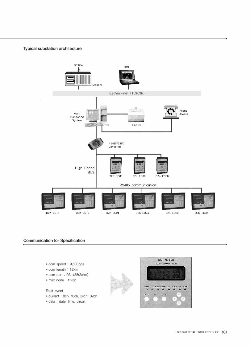
Typical substation architecture
Communication for Specification
Eather -net (TCP/IP)
● com speed : 9,600bps● com length : 1.2km● com port : RS-485(2wire)● max node : 1~32
Fault event● current : 8ch, 16ch, 24ch, 32ch● data : date, time, circuit

102 DEESYS TOTAL PRODUCTS GUIDE
D2K-ED08(8circuit)
D2K-ED24(24circuit)
D2K-ED16(16circuit)
D2K-ED32(32circuit)
Earth Leakage Detector [ELD]
1a(Common)
AC 110/220 ± 15%, 50/60㎐ (Default), DC 110/125 ± 20%
AC 200mA~1000mA (100mA Step), Default-0.5A
0.1~3.0Sec/0.1:±50ms, 0.2~3.0:±15%(0.1sec, Step), Default-0.2Sec
Between 53% and 75% of resonable value
Below 52% of reasonable value
200mA / 100mV(75~125mV at 2㎘ Resistance)
L.C.D(20Char, X 4Line)
MODE,ESC,ENTER,Direction Keys(→,→,→,→)
POWER(green):Indicating the staus of the internal CPU
AUTO(yellow):Resetting of Relay and Lamp[On(Flickering):Auto/Off:Manual]
BUZZER(yellow):Indicating whether of not the buzzer would sound when operating [Off(Flickering):No
Beep/On:Beep]
COMM(yellow):Indicating communication in progress(Flickering)
ZCT:Faulty ZCT connection (unused feeder-Z.C.T Common terminal)
PICK(red):Detecting leakage current when operating
SYS(red):Internal error in the detector(System Error)
ALARM(red):Indicating operation caused by an electric leakage
10 faults(the latest fault is marked with “1”)
Auto Reset/Manual Reset(selected with the program)
`-10~60℃(in operation), -20~70℃(to be kept)
Hideaway Type
AC 250A 5A 0.5sec(L/R=0)
75dB(within 1m)
1’st-ground / 2’nd-ground / 1’st-2nd : 100㏁ or more DC500V Megger
1’st-ground : AC 1,500V
2’nd-ground : AC 500V
1’st-2’nd : AC 1,500V
Aux. power - ground 1.2㎲×50㎲×6㎸ Positive/Negative electronics. 3time
Vibration frequency:16.7㎐ Double amplitude : 0.4㎜ Direction:horizontal, vertical, transverse
Shock acceleration:50G Shock application direction:horizontal, vertical, transverse Shock
8a
D2K-ED08
07-13
8Circuit
16a
D2K-ED16
07-16
16Circuit
24a
D2K-ED24
07-14
24Circuit
32a
D2K-ED32
07-10
32Circuit
Product name
Contact
Model
Certificate No.
Monitoring Circuit
Power Source
Rated Current Sensitivity
Time Setting Range/Deviation
Operating Current
Non-Operating Current
Rated current Z.C.T
Display
Key Method
LED(Lamp)
Fault Memory
Resetting Method
Temperature
Mounting Method
Capacity of contact Point
Buzzer
Insulation Resistance
Withstand voltage
Lighting impulseWithstand voltage
Vibration
Shock times:3 times
Weight 2kg 7kg
Specification
D2K-ED SERIES EARTH LEAKAGE DETECTOR & RELAY

DEESYS TOTAL PRODUCTS GUIDE 103
LED indicatorCPU(RUN)Error checkAuto/Manual SetBuzzer On/Off SetCommunication con.ZCT connection checkPick-up/system check
Key partUp↔Down menuRight↔Left menu
ResetLamp and CPU reset
DisplayGeneral Setting
Level Setting pointFault check
CommunicationSelf test mode
Key PartTop menu modekeyEscape Key menuCursor menu key
Front View
←
←
←
←
←
Menu Specification
START ON DISPLAY- After approving power or pressing the CPU RESETbutton, the LCD will become bright and the screen belowwill be displayed fer about 5 seconds. Then, you will be automatically taken to Display On/Off Mode or Display Mode.
- Default : Display On Mode
DISPLAY ON MODE- If <Display ON Mode> has been preset, you will be automatically taken to the Display On Mode screen 5 seconds after approving initial supplementary power supply or pressing the CPU RESET
IN CASE OF ELECTRIC LEAKAGE
- In Case that an electric leakage has occurred, the screen below is displayed regardless of Display On/Off Mode.
- The event is saved in Fault Memory(up to 10 events).- Press the ESC button to move to Display On Mode.
DISPLAY MODE
- Fd(Feeder) : Circuit Number- S C : Set Amount of Leakage Current- S T : Set Amount of Delay Time for Leakage Alarm- Curr (Current) : Present Leakage Current- F (Fault) : Indicating the Occurrence of Electric Leakage (marked with ‘X’)- The status of each feeder is displayed by rotation. Press the Up/Down key(↑,↓) to quickly move to a desired feeder.
TOP MENU- Press the MODE button in Display On or Off Mode to view the Top MENU screen below. (If no action is taken by pressing any key within 10 seconds in the TOP MENU screen, it will be converted back to the present Display Mode.
DEEsys
D2K-ED Series
V1.00
Fault
FD Curr Date Time
03 0.72 0107 17:36
ㅁ09 1.63 0107 17:36
Fd -SC- -ST- Curr F
01 0.25 0.3s 0.20
02 0.12 0.2s 0.10
03 0.47 0.7s 0.72
T TOP MENU
1.General Set *
2.Level Set
ㅁ 3.Fault Check
Display On Mode
2000 01 01 12:15:36

104 DEESYS TOTAL PRODUCTS GUIDE
● General Set Setting Display On/ Off Mode, Setting Buzzer On/ Off, Setting Auto/ Manual resetting for contact point, Erasing saved events in memory, Setting data and time
● Level Set Setting operating current and delay time
● Fault Check Checking the history electric leakage occurrence (Feeder in which leakage occurred.) Leakage current, Time of leakage occurrence))
● Communication Setting items related to communication
● Test Setting items related to operation test
Sub Menu
System Menu
D2K-ED SERIES EARTH LEAKAGE DETECTOR & RELAY

DEESYS TOTAL PRODUCTS GUIDE 105
- When the message ‘Are You Sure?’ appears on the screen, you can simultaneously apply a new setting to all the feeders by entering Y(YES) and pressing the ENTER button.- After a new setting is saved, you will be taken back to the TOP MENU
COMMUNICATION- Place the blinking cursor on ‘4. COMM SET’ and press the ENTER button. the screen below will appear.
PORT NO
- You can specify a communication port using the Up/Down key.- After a new port is saved, you will be taken to the previous sub menu screen.
BAUD RATE- It is fixed to 9600bps.
PARITY- It is fixed to ‘None’ type.
STOP BIT- It is fixed to 1.
TEST- You must configure as below in order to test the detector manually.
- Place the blinking cursor on ‘5. Test Set’ and press the ENTER button. the screen below will appear.
GENERAL SET- Place the blinking cursor onto ‘1. General Set’ in the TOP MENU and press the ENTER button. The screen below will be displayed.
MEMORY ERASE [YES / NO]- If you press ENTER button from the Memory Erase[Y] screen, the saved fault events will be erased. - After they are erased, you will be taken back to the previous sub menu screen.
SETTING AS “EACH”
- Enter leakage current for each feeder using the Up/Down key. Move to Dt(Edlay time) by pressing the MODE button and set delay time for each feeder using the Up/Down key.- When you are finished with one feeder, you can move to the next one by placing the blinker at the end of the feeder and pressing the Left key.- Repeat the procedure until you finish setting and press the ENTER button. The confirmation message below will appear.
- When the message ‘Are You Sure?’ appears on the screen, you can apply a new setting by entering Y(YES) and pressing the ENTER button.- If there is only feeder to modify, change the value of a specific feeder and simply press the ENTER button.- After new settings are saved. you will be taken to the TOP MENU
SETTING AS “ALL”
- Select ‘ALL’ on the screen above and press the ENTER button. The screen below will be displayed. Enter a new value for leakage current and delay time and press the ENTER button.
G e n e r a l S e t
1 . D i s p l a y [ O n ] *
2 . B u z z e r [ O n ]
ㅁ 3 . R e s e t S e t [ A u t o ]
M e m o r y E r a s e [ N ]
Y E S : U P N O : D O W N
S E T M O D E ( I / d t )
0 1 A [ 0 . 5 ] D t [ 0 . 2 ]
0 2 A [ 0 . 5 ] D t [ 0 . 2 ]
ㅁ 0 3 A [ 0 . 5 ] D t [ 0 . 2 ]
S E T M O D E ( I / d t )
A r e Y o u S u r e . ? ( Y ) \
Y E S : U P N O : D O W
C u r r e n t S e t [ 0 . 5 ] A
D e l a y T i m e [ 0 . 2 ] s
H I : U P L O W : D O W N
C u r r e n t S e t [ 0 . 5 ] A
D e l a y T i m e [ 0 . 2 ] s
A r e Y o u S u r e . ? ( Y )
Y E S : U P N O : D O W N
C O M M S E T M O D E
1 . P o r t N o . [ 0 0 ] *
2 . B a u d r a t e [ 9 6 0 0 ]
ㅁ 3 . P a r i t y [ N o n e ]
To p M e n u
3 . F a u l t C h e c k
4 . C o m m S e t
ㅁ 5 . Te s t S e t
C o m m P o r t N o . [ 0 1 ]
( 1 - 1 6 )
H I : U P L O W : D O W N

106 DEESYS TOTAL PRODUCTS GUIDE
● 8C External Wiring(ED 8 CIRCUIT TYPE)
T1~T8 : “a”
Tcom : Common
PP PN : Ac 110/220V(DC110V)Aux, Power
Ta Tb Tc : Alarm
E : (E3)
Z1~Z8 : ZCT
Zcom : ZCT
A B G : (RS-485) DA:(+), DB(-), DG
T1~T32 : “a”
Tcom : Common
PP PN : Ac 110/220V(DC110V) Aux, Power
Ta Tb Tc : Alarm
E : (E3)
Z1~Z32 : ZCT
Zcom : ZCT
DA, DB, DG : (RS-485) A(+), B(-), G
Wiring
D2K-ED SERIES EARTH LEAKAGE DETECTOR & RELAY
16C 24C 32C

DEESYS TOTAL PRODUCTS GUIDE 107
Terminal arrangement
Dimension
● 8C
● 16C, 24C, 32C
● 8C, 16C, 24C, 32C