
D2.4 Overall Integration Architecture...
88
BATS (317533) D2.4 D2.4 Overall Integration Architecture Definition Instrument Collaborative Project Topic ICT-2011.1.1 Project Title Broadband Access via Integrated Terrestrial & Satellite Systems Project Number 317533 Project Acronym BATS Contractual Delivery Date M6 Actual Delivery Date 07/06/2013 Contributing WP WP2 Project Start Date 01/10/2012 Project Duration 36 months Dissemination Level PU Editor FH-Fk Contributors AVA, AST, TAS-F, TAS-S, MAV, UoS, TT, R, OPT, STM, MUL and CAL
-
Upload
truongphuc -
Category
Documents
-
view
217 -
download
2
Transcript of D2.4 Overall Integration Architecture...

BATS (317533) D2.4
D2.4
Overall Integration Architecture Definition
Instrument Collaborative Project
Topic ICT-2011.1.1
Project Title Broadband Access via Integrated Terrestrial & Satellite Systems
Project Number 317533
Project Acronym BATS
Contractual Delivery Date M6
Actual Delivery Date 07/06/2013
Contributing WP WP2
Project Start Date 01/10/2012
Project Duration 36 months
Dissemination Level PU
Editor FH-Fk
Contributors AVA, AST, TAS-F, TAS-S, MAV, UoS, TT, R, OPT, STM, MUL and CAL

BATS (317533) D2.4
07/06/2013 i
Disclaimer
This document reflects the contribution of the participants of the research project BATS. The European Union and its agencies are not liable or otherwise responsible for the contents of this document; its content reflects the view of its authors only. This document is provided without any warranty and does not constitute any commitment by any participant as to its content, and specifically excludes any warranty of correctness or fitness for a particular purpose. The user will use this document at the user's sole risk.
BATS (317533) D2.4
07/06/2013 ii
Contributors
Name Company Contributions include
Javier Perez Trufero,
Simon Watts AVA 2.1, 2.5, 3.4, 4, 5.2
Nigel Watts CAL 3.3
Osianoh Glenn Aliu, Christian Niephaus, Mathias Kretschmer
FH-FK 1, 2, 5, All
Antonio Rodríguez Del Corral
R 5.4
Rosalba Suffritti,
Enzo Alberto Candreva MAV 3, 4.2, 5.1
Varuna De Silva, Xiyu Shi, Ahmet Kondoz
MUL 3.3, 5.5.1
Xosé Ramón Sousa Vázquez, Antonio Vidal Vidal
OPT 2.5, 5.3
Juan-Manuel Rodriguez Bejarano
TAS-E 4.2
Cihan, Kement, Alper Yesilyurt,
TT 3.2, 5.4
Barry Evans UOS 3, 6
Document History
Version Date Modifications Source
0.1 16/04/13 Document Created FH-Fk
0.2 27/05/13 Contributions from Partners Multiple
QA 28/05/13 Document ready for QA revision FH-Fk
1.0 07/06/13 Document ready for submission FH-Fk
BATS (317533) D2.4
07/06/2013 iii
Table of Contents
List of Figures ......................................................................................................................... v
List of Tables ......................................................................................................................... vi
List of Acronyms ................................................................................................................... vii
List of Common Terms ........................................................................................................... x
Executive Summary ............................................................................................................. xii
1 Introduction .................................................................................................................... 1
1.1 Purpose of this Document ....................................................................................... 1
1.2 Scope of Work ......................................................................................................... 1
1.3 Objectives and Achievements ................................................................................. 1
1.4 Structure of Document ............................................................................................ 2
2 Functional Level Architecture Definitions ........................................................................ 3
2.1 Overall BATS Architecture ....................................................................................... 4
2.1.1 Functionalities of the ING ................................................................................. 4
2.1.2 No ING option .................................................................................................. 5
2.1.3 The Centralized ING......................................................................................... 6
2.1.4 Decentralized ING ...........................................................................................10
2.1.5 Baseline Architectural ING selection ...............................................................11
2.2 BATS Architecture Functional Components ...........................................................13
2.3 Definition of Intelligent Routing and Control Plane within the IUG and ING ............16
2.4 Definition of Interfaces between Functional Components .......................................18
2.5 Specification of Protocols on Interfaces ..................................................................20
2.5.1 Management Protocols in the IUG ...................................................................21
3 Key Challenges and Solutions with Selected IUG Scenarios .........................................25
3.1 IUG Integration .......................................................................................................25
3.1.1 CPE- integration of IUG with modems .............................................................25
3.1.2 IUG Integration for the PIB architecture ...........................................................26
3.1.3 IUG integration for the FIB architecture ...........................................................27
3.1.4 Integration Issues and challenges ...................................................................28
3.2 Operator Integration ...............................................................................................28
3.3 End user system integration ...................................................................................29
3.3.1 Integration of home network and devices with the IUG ....................................29
3.3.2 Traffic Identification .........................................................................................31
3.3.3 Mapping the traffic identification schemes to the IUG architecture...................32
3.3.4 QoE requirements for BATS use cases ...........................................................33

BATS (317533) D2.4
07/06/2013 iv
3.3.5 Recommended Approach to QoE Determination .............................................34
3.4 Research Challenges in the satellite network design for FIB/PIB............................35
4 IUG Prototype Supplier Selection ..................................................................................39
4.1 Summary of IUG supplier selection process and current status ..............................39
4.2 Beauty Contest and Down-selection .......................................................................43
4.3 Final selection of IUG Supplier ...............................................................................46
5 Summary of Working Assumptions ................................................................................47
5.1 Overall Network Assumptions ................................................................................47
5.2 Assumptions for the Satellite Link ...........................................................................48
5.3 Assumptions for the Digital Subscriber Line ...........................................................48
5.4 Assumptions for the Cellular Technology ...............................................................50
5.5 Assumptions used in System Emulator ..................................................................51
5.5.1 Terrestrial Link Emulator .................................................................................51
5.5.2 Satellite Link Emulator .....................................................................................54
5.5.3 Assumptions on subjective experiments for proof of BATS concept (lab trials) 56
6 Conclusion ....................................................................................................................59
7 References ....................................................................................................................61
Annex A - IUG supplier selection process (Additional information) ...................................63
Information captured during process .................................................................................63
Fraunhofer-Fokus ..........................................................................................................63
Xrio................................................................................................................................65
OneAccess ....................................................................................................................68
Forsway ........................................................................................................................74
BATS (317533) D2.4
07/06/2013 v
List of Figures
Figure 1-1: Structure of D2.4 ................................................................................................. 2
Figure 2-1: No ING option ..................................................................................................... 5
Figure 2-2: Centralized ING ................................................................................................... 7
Figure 2-3: Centralized ING located in Satellite Operator Hub with terrestrial network being in a different country. ................................................................................................................. 8
Figure 2-4: Centralized ING located at terrestrial operator POP with Satellite Operator’s Hub being in a different country. ................................................................................................... 9
Figure 2-5: Centralized ING located at POP with Satellite Operator’s Hub being in the same country. ................................................................................................................................10
Figure 2-6: Illustration of possible implementation with INGs located within the satellite operators’ ring of gateways...................................................................................................10
Figure 2-7: Decentralized ING. .............................................................................................11
Figure 2-8 : BATS Architecture showing Functional Modules. ..............................................14
Figure 2-9 : Control, Intelligent Routing and Management Planes Interconnection. ..............17
Figure 2-10 : BATS IUG Function Diagram ...........................................................................18
Figure 2-11 TR-069 family of specifications defined by the Broadband Forum .....................22
Figure 3-1: Hbb solution to integrate broadcast and multicast ..............................................25
Figure 3-2a: A simple home network [1] ...............................................................................30
Figure 3-3: Architecture needed to accommodate the five methods for QoE determination and the Intelligent Routing Engine. .......................................................................................32
Figure 4-1: IUG supplier selection process. ..........................................................................40
Figure 5-1: Scope of a BATS network. .................................................................................47
Figure 5-2 Protocol structure in ADSL2+ connections ..........................................................49
Figure 5-3 Protocol structure in VDSL2 connections ............................................................49
Figure 5-4: Scope of emulation .............................................................................................51
Figure 5-5: Class diagram for the Emulated WLAN Interface ................................................52
Figure 5-6: NetEmu modules for the Emulated Wireless Interface ........................................53
Figure 5-7: Simplified modules for emulating the LTE link. ...................................................54
Figure 5-8: Emulated Satcom System ..................................................................................54
Figure 5-9: OpenSAND architecture .....................................................................................55
Figure 5-10: environment plane architecture ........................................................................56
Figure 5-11: Rating scale to be adopted in subjective experiments ......................................57
Figure 7-1: Xrio's anatomy. ...................................................................................................66
Figure 7-2: Forsway's system. ..............................................................................................74
BATS (317533) D2.4
07/06/2013 vi
List of Tables
Table 2-1: Summary of impacts to routing decisions of different BATS architecture scenarios. .............................................................................................................................................12
Table 2-2: Interface summary. ..............................................................................................19
Table 2-3: Interface protocols. ..............................................................................................20
Table 3-1: R&D challenges with level of complexity depending on scenario. ........................37
Table 4-1: IUG options for lab/field trials (Top 7 candidates). ...............................................41
Table 4-2: Selection table. ....................................................................................................42
Table 4-3: Summary of answers to questionnaire. ................................................................44
Table 4-4: Down-selection weighted table. ...........................................................................45
Table 5-1 xDSL available BandWidth vs. Pair Length and attenuation .................................50
Table 5-2 xDSL Minimum peak capacities ............................................................................50
Table 5-3 Scenarios showing combination of applications with two users.............................58
Table 7-1: IUG Questionnaire - Fraunhofer. .........................................................................63
Table 7-2: IUG Questionnaire - Xrio. ....................................................................................67
Table 7-3: IUG Questionnaire - One Access. ........................................................................70
Table 7-4 IUG Questionnaire - Forsway ...............................................................................74

BATS (317533) D2.4
07/06/2013 vii
List of Acronyms
Abbreviation Definition
AC Alternating Current
ACM Adaptive Coding and Modulation
ADU Application Data-flow Unit
BATS Broadband Access via Integrated Terrestrial & Satellite Systems
BRAS Broadband Remote Access Server
BSS Business Support System
CA Conditional Access
CDN Content Delivery Network
CEN European Committee for Standardisation
CI Communication Interface
C-ITS Cooperative ITS
CoC Code of Conduct
CoMP Coordinated MultiPoint transmission/reception
CPE Customer Premise Equipment
CSI Channel State Information
DLNA Digital Living Network Alliance
DPI Deep Packet Inspection
DRM Digital rights management
DSLAM Digital Subscriber Line Access Multiplexer
DVB Digital Video Broadcasting
EDGE Enhanced Data rates for GSM Evolution
ELV Extra Low Voltage
EoLT End of Life Treatment
EC European Commission
EPC Evolved Packet Core
ESA European Space Agency
ESO European Standards Organisation
ETSI European Telecommunications Standards Organisation
EU European Union

BATS (317533) D2.4
07/06/2013 viii
Abbreviation Definition
FCAPS Fault, Configuration, Accounting, Performance, Security
FDD Frequency Division Duplex
FIB Fully Integrated IUG, BATS operator
FIM Fully Integrated IUG, Multiple operators
FIV Fully Integrated IUG, Virtual operators
FP7 EU 7th R&D Framework Programme
GPON Gigabit Passive Optical Network
GRE Generic Route Encapsulation
HGI Home Gateway Initiative
HSPA High Speed packet Access
HSS Home Subscriber Sever
HTS High Throughput Satellite
ICT Information & Communications Technologies
IEC International Electrotechnical Commission
IETF Internet Engineering Task Force
IMS IP Multimedia Subsytem
ING Integrated Network Gateway
ISP Internet Service Provider
ITU International Telecommunication Union
IUG Intelligent User Gateway
KPI Key Performance Indicator
LAN Local Area Network
LNB Low Noise Block
LTE Long Term Evolution
LVD Low Voltage Directive
MCC MultiCell Cooperation
MIMO Multiple Input Multiple Output
MME Mobility Management Entity
MPLS Multiprotocol Label Switching
MP-TCP Multi Path TCP
NPT Network Prefix Translation
OAM Operations Administration and Maintenance

BATS (317533) D2.4
07/06/2013 ix
Abbreviation Definition
OSS Operational Support System
OTT Over The Top content
PDU Protocol Data Unit
P-GW PDN (Packet Data Network) Gateway
PIB Partially Integrated IUG, BATS operators
PIV Partially Integrated IUG, Virtual operator
POP Point of Presence
QoE Quality of Experience
QoS Quality of Service
RF Radio Frequency
SAP Service Access Point
SELV Safety Extra-Low Voltage
S-GW Serving Gateway
SLA Service-Level Agreement
SNO Satellite Network Operator
STB Set Top Box
TDD Time Division Duplex
TDMA Time Division Multiple Access
UMTS Universal Mobile Telecommunication System
UNK Unknown
VDSL2 2nd
generation Very-high-bit-rate Digital Subscriber Line
VSN Virtual Satellite Network
WAN Wide Area Network

BATS (317533) D2.4
07/06/2013 x
List of Common Terms
Term Description
Customer premise equipment
The equipment required to provide the BATS service located at the customer premise
End user network The network at the customer premise, in BATS this means all connections and devices connected on the LAN side of the IUG. Referred to as either end user network or home network. Home network
Traffic flow The route a sequence of data packets created by an application takes when traversing a network and or within a device such as the IUG. An application may create multiple traffic flows (for example video and audio may be separate traffic flows).
Decomposed service elements
An application such as e-health consists of one or more decomposed service elements such as browsing or VoIP.
Absolute peak (data) rate
The combined data rate if all applications in a household are running at their peak rates at the same time.
Typical peak (data) rate
The combined peak data rate if a typical mix of applications is running at the same time at their typical data rates.
Average (data) throughput
Typically determined by the amount of data transmitted over a given time divided by that time. Generally used to consider peak hours and used to calculate the total presented traffic at an aggregation point such as a DSLAM, a cellular base station or satellite carriers.
Access network Also commonly referred to as the ‘last mile’; links the end user sites to the core network using technologies such as xDSL, 3/4G and satellite broadband.
Core network The central part of a telecommunications network that routes calls or data from the one place to another.
BATS IUG The Intelligent User Gateway of the BATS project is a home device providing broadband access, security, cached storage capacity and QoS provisioning. It does not only provide an interface to access networks, but the BATS IUG will select access delivery routes in multi operator and service provider domains, matched to the QoE needs of individual services. The IUG is able to determine the QoS requirements of applications in real time and make routing decisions accordingly to optimize QoE. It also uses the storage capacity of the IUG for high bandwidth low priority traffic caching during off-peak hours, such OTT TV.
BATS ING The BATS Intelligent Network Gateway is the IUG counterpart on the operator site. It has dual functionalities of remotely managing all associated IUGs as well as act as an interface/gateway to the public internet. It has similar responsibilities as the IUG but on the other edge of the BATS network, i.e. classifying the traffic and intelligently distributing it among the available connections while taking into account QoS requirements and link capabilities.
BATS Operator A single service provider that owns the multiple access network connections to the IUG as a virtual service provider of both satellite and terrestrial (DSL and cellular) network. The BATS operator could be a satellite provider with strong SLA with the terrestrial operator or vice versa. By strong SLA, we refer to the virtual network operator being able to monitor the performance of the leased links to ensure that using a set of agreed KPIs (latency, capacity, delay, etc), a minimum QoS is being provided.

BATS (317533) D2.4
07/06/2013 xi
Term Description
Virtual ISP A Virtual Internet Service Provider is a service provider that does not own the access network connections to the IUG but that buys them wholesale and then sales them to individual end users.
BATS (317533) D2.4
07/06/2013 xii
Executive Summary
The purpose of this document is to provide a functional level architecture and a description of
the integrated BATS system. In the previous deliverable on selection of integration scenarios
(D2.3), seven possible scenarios were presented and discussed. Taking into consideration
the technological challenges, service demands and end user needs, three candidate
scenarios were selected: a Loosely Integrated IUG with BATS operator (LIB), Partially
Integrated IUG with BATS operator (PIB) and Fully Integrated IUG with BATS Operator (FIB)
for lab trials, field trials and a final prototype respectively. The PIB will be used as the
reference scenario. This document builds on these findings for the analysis of the selected
integration scenarios on the basis of their architecture, networking and required protocols.
This analysis thus reveals key challenges with the scenarios selected and proposes potential
directions in order to resolve them.
A key part of this deliverable is the definition of the BATS architecture with regards to its
functionality, interfaces and the protocols used on these interfaces. To serve as a guide in
WP3 and for the rest of the project, descriptions of required and desired functionality of the
Intelligent User Gateway (IUG) and Integrated Network Gateway (ING) are developed.
Further definitions of the working assumptions for the communication links are introduced.
These can be updated in the course of the project based on new research findings. These
initial working assumptions include characteristics of the satellite link, the digital subscriber
line, wireless cellular technology as well as the system emulator. Valued insights into the end
user behaviour using defined scenarios for subjective tests are presented.
The functional modules of the BATS architecture with similar functionalities existing in the
IUG and ING are presented. The management plane is described, highlighting its function for
synchronisation of traffic flows with the ING, policy management and managing local
resources within the IUG and ING. It also executes various policy functions which are pushed
form the ING to the IUG. It should support fault, configuration, accounts, performance and
security management. The control plane ensures synchronised and organised flow patterns
within these devices. The data plane which includes the intelligent routing modules is the
main functional module in the IUG. Its functions include, traffic classification, intelligent
routing of traffic flows and network address translation.
Relevant specifications for the BATS architecture from the TR-069 family of specifications
were presented to guide further activity in WP3. Furthermore a table of protocols for
interfaces in the IUG for the three different integration scenarios was introduced. While most
of these interfaces are similar in all three (FIB, PIB and LIB), the differences are described,
such as the new interfaces to modems.
From this preliminary technical definition work, we derived seven potential research
challenges:
1) Share efficiently the interface between satellite multicast and broadband two-way
SatCom network.
2) Remote management of the Customer Premise Equipment (CPE), modems and
satellite multicast receiver.
3) Ensure confidentiality and security of data through the network.
4) Provide a platform and synergy for integration of the 3 different subscription
components (xDSL, 3G/LTE and SatCom).
BATS (317533) D2.4
07/06/2013 xiii
5) Identify and prioritise traffic, including the determination of the Quality of Experience
(QoE) requirements from observing the data flow.
6) Define policies on forwarding path decisions based on type of service using flow
recognition and traffic prioritisation.
7) Design a reliable centralised ING that is able to cope with faults or failures.
From the perspective of operators, challenges that could arise for integration of a satellite
and terrestrial operators into a single BATS operator include: accounting and billing,
harmonised Service-Level Agreements (SLAs), Operations Administration and Maintenance
(OAM) issues due to integration of different backhaul and access technologies and
regulatory concerns.
An analysis of traffic identification schemes had been done taking into cognisance the
selected IUG integration scenarios. With specific relevance to the BATS use cases, a final
recommendation for the adoption of traffic identification based on the ports used by the
application and a payload method which classifies traffic by analysing headers and payloads
of the packets was considered. The option of still using other traffic identification schemes
remains open and any new scheme developed by the BATS project may be fed into
European standardization working groups on cooperative systems.
In testing new findings developed in the course of this project a potential IUG/ING supplier
has to be selected. A detailed process of selecting such a partner based on technical
information presented by prospective candidates is documented. This specifically describes
the second step of the IUG supplier selection process (beauty contest). Further details on the
potential candidates are provided in the appendix. From 22 potential suppliers narrowed
down to 7, 3 remaining candidates are being evaluated for a final selection.
Finally, we describe the working assumptions to be used both for the emulator, lab trials as
well as field trials.
The achievements of this deliverable and its inputs to future work packages are:
Consolidated inputs from earlier deliverables and provide a focussed perspective on
the overall BATS architecture by summarising definitions. This will be relevant for all
subsequent work packages as well as the description of work to be provided to the
IUG supplier.
Provided a functional level architecture and group the components of the evolving
final BATS architecture into functional groups.
Defined the interfaces as well as the protocols required for the communication
between the functional components, with focus on internal communication within the
IUG and with the ING. This feeds directly into WP3.1 for the design coordination as
well as the integrated architecture that will be standardised in WP8.
Provided an understanding of various research challenges associated with the FIB,
PIB and LIB scenarios. This guides decisions to be made in the lab and field trials in
WP6 and WP7.

BATS (317533) D2.4
07/06/2013 1
1 Introduction
1.1 Purpose of this Document This document aims to provide a functional level architecture and description of the BATS integrated system. The integration scenarios selected in D2.3 are analysed on the basis of their architecture, networking and protocols requirements. The document provides definitions of the architecture, networking and the required protocols. It serves as an input for WP3. Any overlaps or recaps between D2.3, this document and WP3 are intended to ensure continuity of the entire documentation.
1.2 Scope of Work In the previous deliverable on the selection of integration scenarios (D2.3), seven possible scenarios were presented and discussed. Taking into consideration the technological challenges, service demands and end user needs, three candidate scenarios have been selected: a loosely integrated IUG with BATS operator (LIB), Partially Integrated IUG with BATS operator (PIB) and fully Integrated IUG with BATS Operator (FIB) for lab trials, field trials and a final prototype respectively. The PIB is the reference scenario as highlighted in D2.3.
We now provide a more technical analysis of these selected scenarios, their associated challenges and associated solutions. We put a particular focus on the architecture definition of the IUG, its components, data and control planes, interfaces and associated protocols. To serve as a key input to WP3, a supplier for the IUG prototype will be selected and a summary of working assumptions is specified. These working assumptions include assumptions for the satellite link, the digital subscriber line, wireless cellular technology as well as the system emulator. Valued insights into the end user behaviour are also discussed.
1.3 Objectives and Achievements The objectives in this deliverable and its inputs to future work packages:
Consolidate inputs from earlier deliverables and provide a focussed perspective on the overall BATS architecture by summarising definitions. This will be relevant for all subsequent work packages as well as description of work to be provided to the IUG Supplier.
Provide a functional level architecture and group the components of the evolving final BATS architecture into functional groups.
Define the interfaces as well as the protocols required for the communication between the functional components with focus on internal communication within the IUG and with the ING. This feeds directly into WP3.1 for the design coordination as well as the integrated architecture that will be standardised in WP8.
Provide an understanding of various research challenges associated with the FIB, PIB and LIB scenarios. This guides various decisions to be made in the lab and field trials in WP6 and WP7.

BATS (317533) D2.4
07/06/2013 2
1.4 Structure of Document
The deliverable consists of 5 main chapters.
Chapter 2 presents some key definitions as well as a discussion on the functional modules in the BATS architecture. Descriptions of the management plane, control plane, data plane and other functional modules as well as their interactions are provided.
Chapter 3 takes the functional definitions provided in chapter 2 as well as the IUG scenarios selected in D2.3 to provide some discussion on the particular challenges that could arise with these scenarios as well as possible solutions to them.
Chapter 4 provides the reader with all the information relevant to the second and third steps of the IUG supplier selection process (beauty contest and final decision). Further details of the potential candidates are provided in the appendix.
In Chapter 5, based on the finalised IUG functionalities, architecture and supplier, the working assumptions to be used both for the emulator, lab trials as well as field trials are described.
The structure is summarised by Figure 1-1.
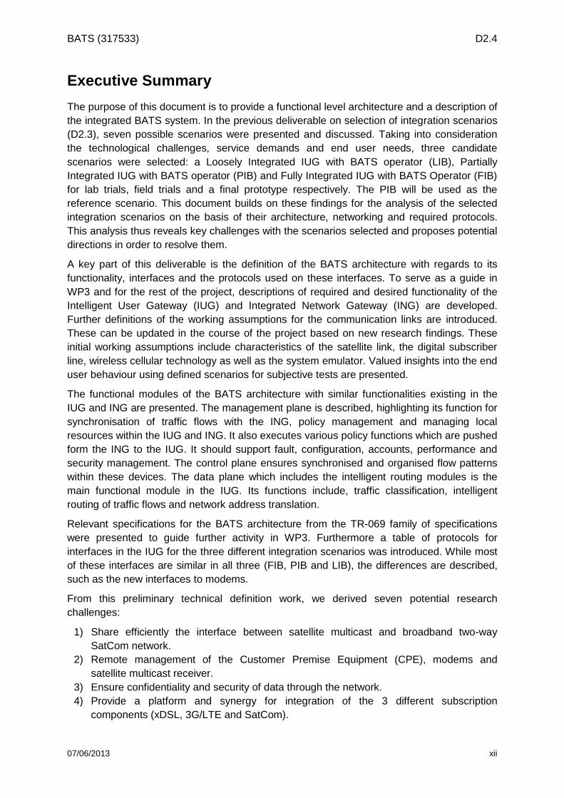
Figure 1-1: Structure of D2.4

BATS (317533) D2.4
07/06/2013 3
2 Functional Level Architecture Definitions
To have a better grasp of the key building blocks in the proposed BATS architecture and their functions, this chapter presents a functional level architecture as well as definitions of each module specified in the IUG, ING and the communication network. A description of the BATS network structure and the selected options from D2.3 are first defined. Section 2.1 gives the overall architecture with emphasis on the ING. In section 2.2, the functional modules of the BATS network are described. Sections 2.3 and 2.4 focus on the definition of interfaces as well as the protocols used on these interfaces. Although this chapter has been systematically developed, the final functionalities of the overall architecture with particular focus on the IUG might vary slightly as this is still on-going research effort with further details on the components to be specified in WP3.
BATS Network Structure
A BATS operator is a single service provider that manages the multiple access network connections to the IUG as a virtual service provider of both satellite and terrestrial (DSL and cellular) network. The BATS operator could be a satellite provider with strong Service-Level Agreements (SLAs) with the terrestrial operator or vice versa. By strong SLAs, we refer to the virtual network operator being able to monitor the performance of the leased links to ensure that by using a set of agreed Key Performance Indicators (KPIs) such as latency, capacity and delay, a minimum QoS is being provided to the end user. It is assumed that the BATS operator manages the CPE IUG and the ING in all the selected scenarios. This is required for management of the BATS services. A LTE/3G cellular network operator may handle the LTE/3G cellular modem. A SatCom network operator will handle the SatCom modem and the satellite multicast receiver. An xDSL network operator handles the xDSL modem.
The BATS operator may, as described for the different scenarios, take on several of the different network operator roles, or may act as a multi-homed Virtual Network Operator (VNO) hosted on each physical network that is assumed to be shared with other users. This sharing can be an applicable scenario in a physical network where the concentration of BATS users is insufficient to effectively share the physical resources of the network. This situation may potentially be avoided particularly in a satellite network due to its relatively large coverage area compared to the terrestrial networks.
The BATS reference scenario selected in D2.3 is:
Partially integrated IUG w/BATS operator (PIB)
The PIB scenario is in-between FIB and LIB (see below) with at least one modem implemented as an external unit. This option will suit integration of satellite modem with the multicast data streams leaving the volume production xDSL modem and cellular modem external (or vice versa). Compared to having all three modems as separate external units, this reduces the number of boxes and makes the solution more attractive to the user. However, it is not as attractive as a fully integrated CPE platform as used in the FIB scenario.
The following options were also identified as possible:
Fully Integrated IUG w/BATS operator (FIB)
The FIB scenario has advantages but the technology required to fully integrate all the modems with the IUG is not yet available. In particular, the satellite modem is not available as a USB or PCI device and thus the FIB scenario is neither considered a viable option for the lab trials nor field trials. A single consolidated BATS operator is not considered a critical aspect for the lab trials but would generally be a simplification for a user and would also

BATS (317533) D2.4
07/06/2013 4
simplify a higher level of integration of the CPE platform. This may prove to be the most attractive architecture for commercial implementation, with a lower manufacturing cost (fewer cases), easier to install, lower maintenance cost (fewer external connections) and the lowest power consumption and embedded carbon footprint using a single PSU.
Loosely Integrated IUG w/BATS operator (LIB)
The LIB scenario is similar to the PIB scenario but with all the modems external to the IUG. All the technology is available but the interconnection at network interface between the modems and the IUG would need to be implemented. There would be flexibility to set up individual paths that would suit the lab trials but having many boxes would not be an advantage for the field trials nor in the eventual product. The different SLAs required may be complex and this may be a risk for the field trials.
2.1 Overall BATS Architecture Based on the selected integration scenarios in D2.3, the overall BATS architecture needs to be integrated with the rest of the public internet and other Internet Service Providers (ISPs) without creating extra delays or overheads on the service delivery. To achieve this, various architectural designs were evaluated and the major differences in these options stem from the location of the ING in the core network and the protocol used for communication among the BATS network gateways. We considered whether the ING is needed as a pivotal part of the overall architecture and, if so, where would be the optimum location of this intelligent gateway.
The BATS Intelligent Network Gateway (ING) is the IUG counterpart on the operator site. It has dual functionalities of remotely managing all associated IUGs as well as acting as an interface/gateway to the public internet. It has similar responsibilities to the IUG but on the outer edge of the BATS network, i.e. classifying the traffic and intelligently distributing it among the available connections while taking into account QoS requirements and link capabilities. In the upstream link, the ING also acts as a concentrator of the different flows sent by the IUGs over the different access networks. The main functionalities of the IUG are described in the next section.
2.1.1 Functionalities of the ING
Monitoring
Continuous monitoring is essential to provide QoS/QoE. Monitoring can be done on various layers. Monitoring can be done solely on the IUG in case of the absence of an ING or on both in cooperation. Particularly the IUG might receive information on the link status directly from the modem which could be reported to the ING. The ING may also be able to get forward link information from the VSAT hubs at the gateways and devices in the core terrestrial networks.
Also, the ING(s) would ‘see’ all traffic generated by or sent to the BATS users, hence it can complement the monitoring information of the IUG. Particularly if the monitoring information is gained from actively measuring the connection and/or monitoring the traffic but not with a more close interaction with the lower layer monitoring system of the operators, having a monitoring point on both edges of the network can become extremely helpful.
Intelligent routing and traffic splitting/combining
On the upstream, from the IUG to a non-BATS user or server, traffic flows of one application/service might have been routed towards different access networks based on their QoS/QoE requirements. The ING needs to ensure that the traffic flows are synchronized and combined again into a single data flow before sending them towards the public Internet so the non-BATS user can receive the data packets appropriately. On the downlink, the ING
BATS (317533) D2.4
07/06/2013 5
may take intelligent routing decisions by detecting the different flows of an application/services and based on the QoS/QoE requirements, decide towards which access network the dataflows are sent. In the case that bandwidth needs to be maximised, the ING needs to be able to perform splitting/bonding of the different packets of each flow.
Management of IUGs
New policies might need to be pushed to the IUG, such as updating the classification engine, introducing new operator policies etc. This functionality is desired to be coordinated at a central point in the network architecture and is essential in the management of the IUGs. For example, the ING might push such information via regular firmware or configuration file updates.
In defining the overall BATS architecture and the location of the ING in the system, three possible options have been identified and discussed in this section.
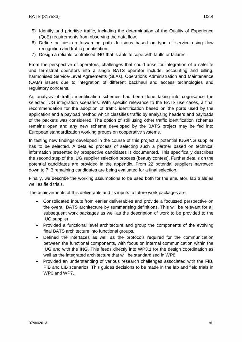
2.1.2 No ING option
In the ‘no ING’ option the IUG is the only intelligent entity of the BATS system, as depicted in Figure 2-1. The three different operators, namely the DSL, the mobile and the sat operator have no common infrastructure or component. The IUG has (at least) one public IPv6 address from each of the operators. Moreover, each operator provides an IPv6 prefix. These prefixes are all advertised by the IUG in the home network. Hence, an end user device might have two or three public IPv6 address.
National Network
International Network
MNO Network(PLMN)
SNO Network
POPPOP
DSL SegmentBRAS DSLAM
World Wide WebPublic IP Network
POP
POP
POP
IUG Home network
BATS user
Figure 2-1: No ING option
The uplink traffic directed from end user devices towards the internet can be classified by the IUG. The IUG can also select the most appropriate network via which the traffic should be routed taking into account the traffic’s QoS requirements. However, as an end user device will randomly select one of its available IPv6 addresses, the IUG has to perform Network Prefix Translation (NPTv61) in order to avoid a filtering of the IP packets in the operators network. For example, if an end user device wants to establish a VoIP call and chooses an IP address with the IP prefix provided by the SAT operator. The IUG recognizes that the
1 http://tools.ietf.org/html/rfc6296

BATS (317533) D2.4
07/06/2013 6
traffic is a VoIP call and should not be routed via the SAT link but via the xDSL link. If the IP packet would be sent as it is, via the DSL network, the DSL operator will most probably filter the packet because the source IP does not belong to one of the prefixes the operator is responsible for. Hence, the IUG has to perform NPTv6 and replace the prefix of the IP address by the DSL operator.
However, if a new traffic flow from the Internet to the end user is initiated in a way not detected by the IUG, the flow will route via the initiating path whether this is the correct path or not. For example an HD video requested “in game” within the gaming data flow or generated by the game host will be returned over a terrestrial link and not over the preferred satellite link. Or, perhaps the distant end connection on a Skype call (routed correctly over the available xDSL connection) initiates a file transfer, this could be sent over the same connection and not the preferred high bandwidth satellite connection.
By changing the source IP address, the IUG makes sure that the corresponding downlink traffic, from the internet towards the IUG and the end user device, is routed back via the same access network since the connection establishment is initiated by the IUG and IP services in the internet send back the traffic to the source address. However, if the connection establishment is initiated by a non-BATS user, the IUG has only limited means to influence the route of the traffic since the connection initiator simply sends the traffic to one of the IP addresses of the end user’s IUG. DNS tricks might help to slightly influence this decision but compared to the highly dynamical decision the IUG can perform for the uplink traffic. These means are usually fairly limited.
2.1.3 The Centralized ING
In order to provide a single connection point to non-BATS networks, for all users and also for the IUG upstream traffic flows, a centralized ING2 could be used. The ING is expected to be operated by the BATS operator, this being a satellite, cellular or DSL operator, or a fully virtual network operator. Either way, the ING provides a single point of contact from traffic direct from/to a non-BATS user towards/from a BATS user, as depicted in Figure 2-2. Each IUG has exactly one ING to which it corresponds. Out of the scope of this section is the definition on how the BATS operator would handle the failure of one ING and the re-allocation of its IUGs traffic.
2 Due to scalability and reliability reasons most probably multiple INGs are used. For the sake of
simplicity they can logically be seen as one.

BATS (317533) D2.4
07/06/2013 7
Public WWW
Cellular Operator’s
Core Network
Satellite Hub
POP
IUG
POP
DSL SegmentBRAS
DSLAM
INGINGINGNon
BATS ISPNon
BATS ISPNon
BATS GW
Independent ISP network
BRAS: Broadband-Remote Access ServerPOP: Point of Presence
DSL: Digital Subscriber LineDSLAM: DSL Access Multiplexer
ISP: Internet Service ProviderGW: Gateway of ISP
High speed carrier grade link Non-BATS userNon-BATS user
POP
Figure 2-2: Centralized ING
Potentially tunnels, e.g. VPN, GRE3 or MPLS4, can be established between each IUG and the corresponding ING. Obviously, the IUG has also in this case multiple IP addresses from the different network operators but they are only used to establish the tunnels and only one IPv6 prefix will be announced to the home network, namely the one the IUG receives from the ING. Hence, NPTv6 will not be necessary. Depending on the owner/operator of the ING this prefix might be also ‘owned’ by one of the network operators or by a virtual operator.
Moreover, as all traffic from/to an IUG passes an ING the complexity introduced by simultaneously utilizing multiple connections can be hidden and can appear as a single connection to the outside word, i.e. end user devices and non-BATS users. Similarly, the downlink traffic can be explicitly classified and distributed to the available link. Hence, traffic of connections, which are initiated by a non-BATS user can be classified and intelligently distributed and the selected link can be transparently changed during a connection.
The centralized architecture proposes to have a central point for the ING serving as a sink point for the multiple communication links of the BATS architecture. This is connected to the Point of Presence (POP) of both the satellite hub and POP/BRAS of the terrestrial link via dedicated carrier grade links. From an operating point of view, two main possible alternatives have been identified:
The BATS service is offered within a country via a terrestrial virtual network operator, such as R in Spain, which has strong SLAs with DSL and cellular terrestrial broadband service providers. In addition, to offer the BATS service such a VNO would have also wholesale capacity from an international/national broadband satellite operator, which may or may not have the Satellite HUB in that corresponding country.
The BATS service is offered within a country via an international/national broadband satellite operator which has strong SLAs with DSL and cellular terrestrial broadband service providers operating within that corresponding country. The satellite operator may or may not have a Satellite hub in that country.
3 http://tools.ietf.org/html/rfc2784.html
4 http://datatracker.ietf.org/doc/rfc3031/

BATS (317533) D2.4
07/06/2013 8
Different cases depending on the location of the ING and the Satellite GW and the impact of such architectures are described in the following subsections.
2.1.3.1 Central ING located at Satellite Operator Hub with terrestrial network being in a different country
In this scenario, the BATS INGs are located in the POPs of the satellite operator HUBs which happens to be in a different country from which the BATS service is provided. In any case, given the fact of targeting the remote and rural areas and considering the expected move towards Video on Demand (VoD) being the main component of IP traffic, most of the traffic will have to go over the satellite component of the network and hence the proposed architecture does not impose a big limitation in terms of the need to transmit large amounts of satellite traffic via international carrier grade links. However, for the low latency applications which have to rely on terrestrial technologies, the fact of having to route all traffic via the ING, with this being in a different country, will increase the latency of such communications and impact the QoS of latency-sensitive services.
International Network
National Network
WWW
MNO Network(PLMN)
SNO Network
POP
IUG
POP
DSL SegmentBRAS
DSLAM
INGING
ING
Figure 2-3: Centralized ING located in Satellite Operator Hub with terrestrial network being in a different country.
2.1.3.2 Central ING located at terrestrial operator POP with Satellite Operator Hub being in a different country
In this scenario, the INGs are located in a POP within the country in which the BATS service is provided. The INGs can either be co-located with the BRAS of a DSL operator, with the POP of a cellular operator or in a POP of the BATS operator which is a fully VNO (as shown in Figure 2-4). In this scenario, the international satellite operator HUBs are not located in the same country. The fact of having to route all the satellite data (which is envisaged to be the main component in the BATS service) to the satellite GW over a large distance in a high

BATS (317533) D2.4
07/06/2013 9
speed carrier grade link may impose limitations and high operational expenditures for such an architecture.
National Network
International Network
WWW
MNO Network(PLMN)
SNO Network
POP
IUG
POP
DSL SegmentBRAS DSLAM
INGING
POP
ING
Figure 2-4: Centralized ING located at terrestrial operator POP with Satellite Operator’s Hub being in a different country.
2.1.3.3 Central ING located at POP in same country as Satellite Operator Hub
In this scenario, the main difference is that the satellite operator has a hub in the same country in which the BATS service is provided. In such a case, the BATS INGs can be either co-located with the satellite hub, with the DSL BRAS, with the POP of a cellular operator or in the POP of the BATS operator (as shown in Figure 2-5). This architecture minimizes the latency for terrestrial data as compared to the scenario in subsection 2.1.3.1 and minimizes the traffic “tromboning” of the high volume satellite data as compared with case in subsection 2.1.3.2. This scenario is likely to happen with the next generation of high throughput multibeam satellite systems in either Ka or Q/V band. One possible implementation of this case is illustrated in Figure 2-6, where the INGs are located in the satellite operator’s ring of gateways with a POP in all countries in which the BATS service is provided.

BATS (317533) D2.4
07/06/2013 10
National NetworkWWW
MNO Network(PLMN)
SNO Network
POP
IUG
POP
DSL SegmentBRAS DSLAM
INGING
POP
ING
Figure 2-5: Centralized ING located at POP with Satellite Operator’s Hub being in the same country.
Satellite Operator National
POP
Sarellte gateways
Internet
Satellite operator national POP
Ring Routers
INGs
National operator
Internet
xDSL network
MNO (PLMN) network
National operator
Figure 2-6: Illustration of possible implementation with INGs located within the satellite operators’ ring of gateways.
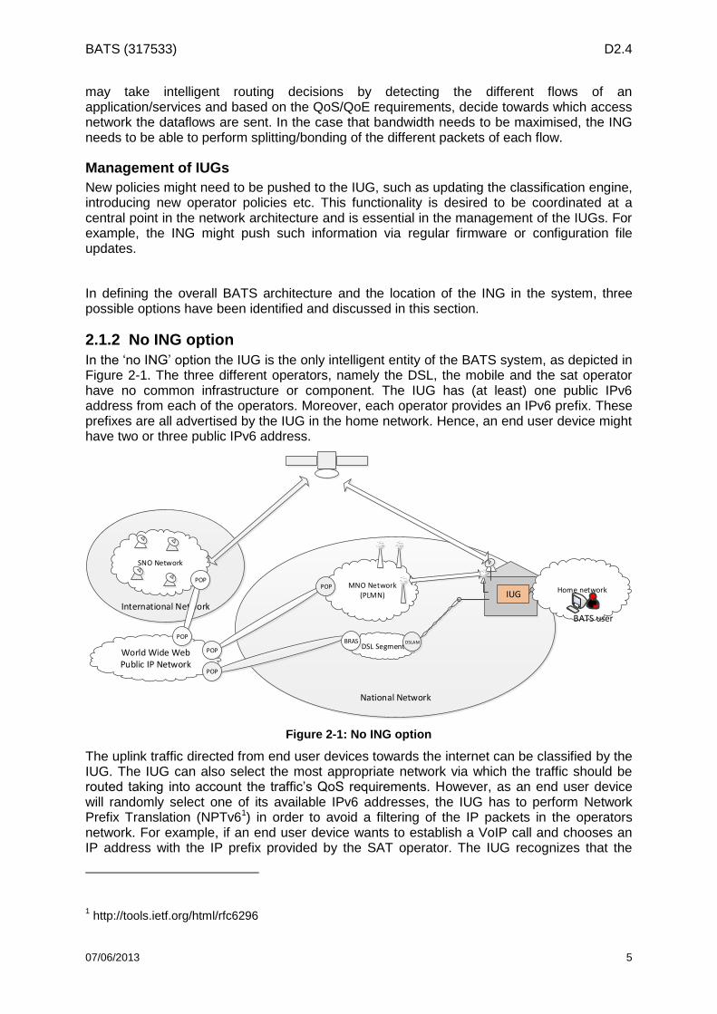
2.1.4 Decentralized ING
Instead of having a centralized ING, multiple INGs operating in a distributed manner are also an option. The INGs are located in each operator network and are interconnected in order to share information about the available links and to forward traffic to another network if this would be more suitable, e.g. traffic of a VoIP call arriving at an ING at the SAT network will be forwarded to the ING in the DSL network.
BATS (317533) D2.4
07/06/2013 11
International Network
National Network
WWW
MNO Network(PLMN)
SNO Network
POP
IUG
POP
DSL SegmentBRAS DSLAM
Signalling
Signalling
Signalling
INGINGINGINGING
ING
INGINGING
UK
Spain
Spain
Figure 2-7: Decentralized ING.
Traffic from the internet towards a BATS user is routed to one of the INGs, either randomly or somewhat controlled by modifying priorities in the BGP routes. However, similar to the ‘no ING option’ this cannot be done on a per flow basis or by taking the traffic class into account, so the level of intelligent routing in the downstream would be quite limited. For example, a new traffic flow from the internet to the end user will route via the initiating path whether this is the optimal path or not. In the upstream, from the IUG to the internet, synchronization issues might arise when the IUG sends traffic flows from the same application towards different access networks.
Other functionalities (see next section) can be realized similar to the ‘centralized ING’ approach. The major difference is that potentially more control overhead is required between the INGs working in a distributed manner.
2.1.5 Baseline Architectural ING selection
The BATS concept relies on using multiple, heterogeneous communication networks simultaneously and complementary in order to provide high quality broadband connections to end users in unserved and underserved areas. This can be realized in different ways. As described in previous deliverables, it is obvious that an IUG is required to instantiate the intelligent routing mechanisms, which are needed to gain benefit from utilizing multiple access networks. Having a counter part of the IUG on the network side (called the ING) brings enhanced possibilities of integration for the end users and the operators. The functionalities and the potential locations of the ING (e.g. in the SNO hub, the MNO POP, etc.) have been evaluated as well as a centralized or a decentralized design. It can be concluded that an ING has first and foremost an impact on the routing, particularly on the routing of packets sent from any non-BATS user or service to a BATS user ‘behind’ the IUG. A centralized ING simplifies the routing as it acts as a single point of contact to the BATS network for all non-BATS users/networks and the internet. It also hides the complexity of the BATS system from both BATS and non-BATS users. Moreover, having an ING (either centralized or distributed), allows to intelligently select to which access networks application flows on the downlink traffic are routed, whereas without an ING this can only be done in a limited and indirect fashion by using protocols such as Network Prefix Translation (NPT).
BATS (317533) D2.4
07/06/2013 12
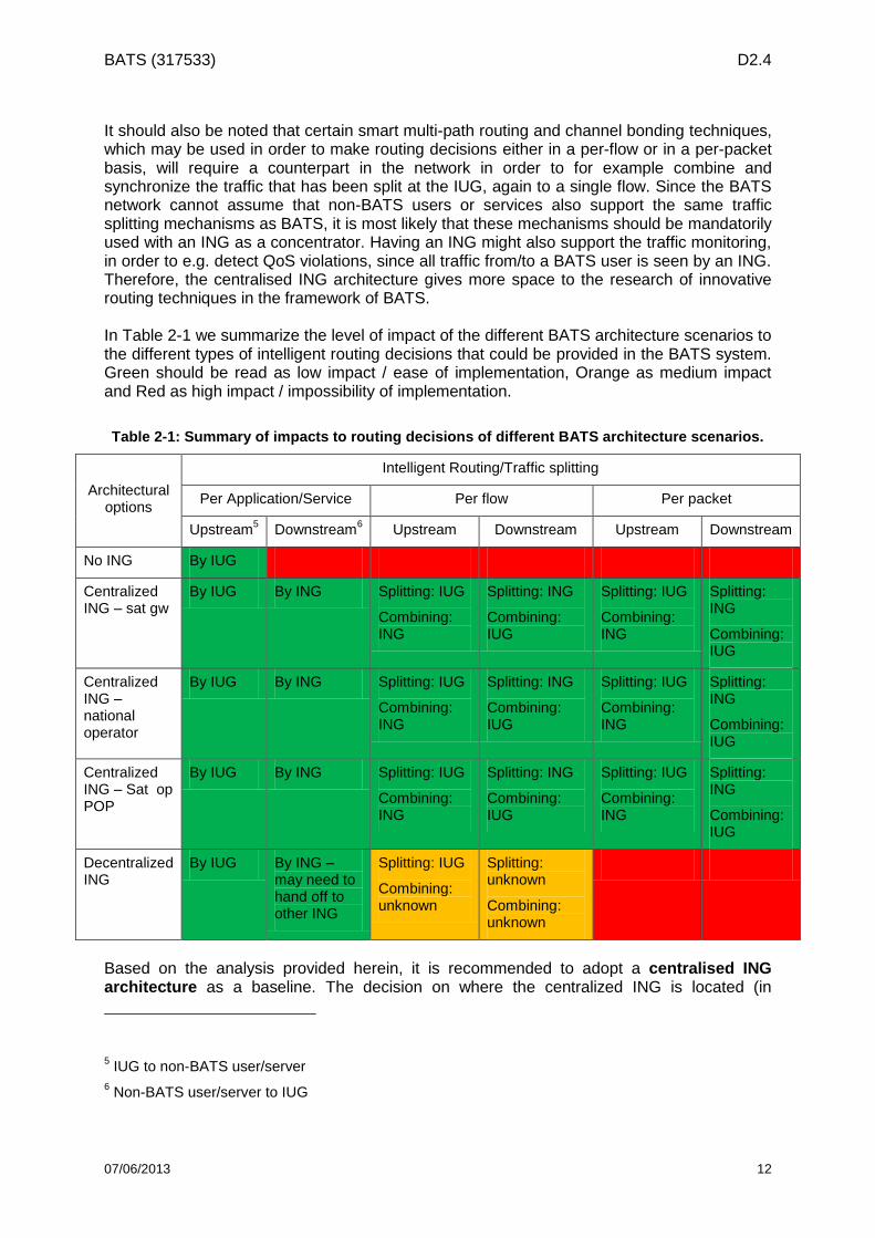
It should also be noted that certain smart multi-path routing and channel bonding techniques, which may be used in order to make routing decisions either in a per-flow or in a per-packet basis, will require a counterpart in the network in order to for example combine and synchronize the traffic that has been split at the IUG, again to a single flow. Since the BATS network cannot assume that non-BATS users or services also support the same traffic splitting mechanisms as BATS, it is most likely that these mechanisms should be mandatorily used with an ING as a concentrator. Having an ING might also support the traffic monitoring, in order to e.g. detect QoS violations, since all traffic from/to a BATS user is seen by an ING. Therefore, the centralised ING architecture gives more space to the research of innovative routing techniques in the framework of BATS. In Table 2-1 we summarize the level of impact of the different BATS architecture scenarios to the different types of intelligent routing decisions that could be provided in the BATS system. Green should be read as low impact / ease of implementation, Orange as medium impact and Red as high impact / impossibility of implementation.
Table 2-1: Summary of impacts to routing decisions of different BATS architecture scenarios.
Architectural options
Intelligent Routing/Traffic splitting
Per Application/Service Per flow Per packet
Upstream5 Downstream
6 Upstream Downstream Upstream Downstream
No ING By IUG
Centralized ING – sat gw
By IUG By ING Splitting: IUG
Combining: ING
Splitting: ING
Combining: IUG
Splitting: IUG
Combining: ING
Splitting: ING
Combining: IUG
Centralized ING – national operator
By IUG By ING Splitting: IUG
Combining: ING
Splitting: ING
Combining: IUG
Splitting: IUG
Combining: ING
Splitting: ING
Combining: IUG
Centralized ING – Sat op POP
By IUG By ING Splitting: IUG
Combining: ING
Splitting: ING
Combining: IUG
Splitting: IUG
Combining: ING
Splitting: ING
Combining: IUG
Decentralized ING
By IUG By ING – may need to hand off to other ING
Splitting: IUG
Combining: unknown
Splitting: unknown
Combining: unknown
Based on the analysis provided herein, it is recommended to adopt a centralised ING architecture as a baseline. The decision on where the centralized ING is located (in
5 IUG to non-BATS user/server
6 Non-BATS user/server to IUG
BATS (317533) D2.4
07/06/2013 13
international satellite GW, in national terrestrial operator POP, in national satellite operator POP, in BATS operator POP, etc.) is left open and will be analysed later in the project considering QoS, cost and operational impacts (WP3 and WP5). Furthermore, additional non-routing related functionalities of a potential ING have been discussed in the previous section, such as remote management and maintenance of IUGs, the provision of information on the QoE requirements of the different services and applications (i.e., look-up tables), traffic monitoring and so forth. Most of those features are essential to be provided by a BATS operator. They are, however, not necessarily implemented on the ING but rather somewhere in the BATS operator network, such as the Network Management System (NMS). Hence, they can be considered independent of the selected ING option. Notwithstanding all of these discussions with regards to the requirement for the ING, accommodation of the widest practical network implementations remains an objective. To achieve this the IUG is expected to continue to function as a WAN termination and sharing device that improves the user QoE even in the absence of an ING but not to the same level as in those networks equipped with the ING functionality. This has the secondary benefit of providing additional resilience against certain network failures or incorrect configuration due to operator, installer or user errors.
2.2 BATS Architecture Functional Components In describing functional components, the IUG is used as reference as most modules carry
out similar functions in both the IUG and ING. Figure 2-8 shows the main components of the
IUG, ING and communication network grouped into different functional modules. This is
developed based on the architecture diagram presented in chapter 6 of Deliverable 2.3.
These blocks do not indicate any specific implementation assumptions or interconnection of
components.

BATS (317533) D2.4
07/06/2013 14
Communication Link
IUG Functional Modules
Intelligent Routing Plane
LAN InterfaceLink
Abstraction
MODEMS
Power Supply
WAN Interface
Management Plane
Control Plane
Traffic Classifier
Traffic Splitting/Combining
Intelligent Cache Controller
LAN Connectors (Wired & Wireless)
Cellular WAN Connector
xDSL WAN Connector
Satellite WAN Connector
Multicast Connector
Satellite Modem
xDSL Modem
Network Address Translator
Memory
OTT Cache
Link Capability Estimation
3G/4G Modem
Security
Intelligent Routing Engine
IUG Manager
ING Functional Modules
Intelligent Routing Plane
Link Abstraction
Power Supply
Security
Management Plane
Control PlaneIntelligent Cache
ControllerMulticast Connector
Memory
Link Capability Estimation
Security
DSLAM
CellularOperatorNetwork
eNodeB
xDSLOperatorNetwork
SatelliteOperatorNetwork
Hub
Home Network
Content Provider
Internet/Backbone
Content Provider
Operator CDN
Internet/Backbone
IUG OAM
IP to QoE Mapping
Security
WAN Interface
Cellular WAN Connector
xDSL WAN Connector
Satellite WAN Connector
Traffic Classifier
Traffic Splitting/Combining
Network Address Translator
Intelligent Routing Engine
LAN Interface
LAN Connectors (Wired & Wireless)
Figure 2-8 : BATS Architecture showing Functional Modules.
Management Plane: The management plane groups all functions related to the system
operation and tasks between various components. This also includes traffic flows,
synchronization with the ING, policy management and managing local resources within the
IUG. In managing the local resources, this plane is directly connected and oversees the
operation of all other functional modules within the IUG. This logical module also supports
the data processing unit for efficient admission control of traffic. All local functions within the
IUG such as initial setup, remote configuration, firmware updates, power usage and other
high level policy functions are executed here. The policy function contains various policies
required for service requests from other modules in the IUG. For example, information on the
QoS/QoE mapping policy is evaluated by a specific policy function which activates the
required service flows in the data processing unit (e.g. traffic classifier). In general, it
provides a plane for managing all service flows through the IUG with their respective policies.
The management plane of the IUG should support the FCAPS operations defined by the
ITU-T M.3400 recommendation. This document specifies five management functional areas
(FCAPS) that need to be supported by the IUG to be operated by an operator:

BATS (317533) D2.4
07/06/2013 15
• Fault management: Detect, isolate, notify, and correct faults encountered in the
network. This will include system level reconfiguration: revising the association of
each IUG to an ING, if the normally used ING develops a fault.
• Configuration management: Configure aspects of network devices, such as
configuration file management, inventory management, and software management.
• Accounting management: Collect usage information of network resources. It also
coordinates network usage rights for example if different price plans exist for one or
more of the WAN access services or fair usage policies.
• Performance management: Monitor and measure various aspects of performance
so that overall performance can be maintained at a defined level.
• Security management: Secure access to network devices, network resources, and
services to authorized individuals.
Control Plane: The control plane ensures that interactions between various components of
the IUG do not take place in an ad-hoc way but are synchronised in organised pattern flows.
In general, the control plane can be viewed as a module that ensures that various defined
policies are executed in an organised and efficient way. For specific traffic flows to the data
processing unit, user and flow authentication with the security module and flow control
synchronisation in the modems are all coordinated here. The amount of control plane traffic
is critical in the IUG design as it increases with the number of possible traffic paths [3] and
even further when traffic splitting is initiated. As the IUG would possibly support CDN, OTT
cache, and DPI, the processing speed of the IUG will be dependent on efficient design of its
control plane.
Intelligent Routing Plane: The main module of the IUG provides a variety of routing
functions. These include network address translation, traffic classification, traffic
splitting/combining and intelligent routing of traffic flows. It also ensures proper flow control
between these components in synchronism with the control plane. To distribute user traffic
among the available network connections, inputs from the link abstraction module on the link
state of the various communication links, defined QoS policies, QoS/QoE mapping tables
and input from its embedded traffic classifier are all required to make intelligent routing
decisions. In general, this module is responsible for all components that receive, process and
transmit data within and through the IUG.
To aid routing decisions for selected service flows, the ING will allow its associated IUGs
access to its central resource. This is to facilitate the determination of the QoE requirement
for a service operated from a specific IP address or port, and to interpret the findings using
schemes such as Deep Packet Inspection.
Memory: This is the local storage module of the IUG and contains both volatile and non-
volatile memory units. Its capacity will be determined from further tests and the various types
of applications it would support. The main component providing this functionality is the OTT
cache. It helps to buffer multicast live streams giving the end user the flexibility to manage
live streams. Other cached data might include current software upgrade downloads that have
been broadcast to all IUGs. A local partition that stores information required by the
management plane such as QoS/QoE mapping tables and routing tables can be supported.

BATS (317533) D2.4
07/06/2013 16
Security: This supports basic authentication of users and intrusion prevention features.
Policies defining the connection to home network, access lists of connected devices,
firewalls, and well as preventing potential misuse of the operator’s communication links. It
also provides encryption and decryption of data through the IUG. In defining the security
policies, it should be noted that to enable intelligent routing, periodic information of link states
from the modems might be required. Also if conditional access to the OTT cache is enabled
sufficient authentication of devices connecting through that interface would be desired.
LAN Interfaces: The LAN interface and its associated wired/wireless LAN connectors
provide a means for the customer’s local home network access to the IUG. The defacto
connection is via a fast Ethernet 100BASE-TX connector. Its main functionality will include
the serving as an ingress point of all the traffic from the home network with a unique IP
address to the intelligent routing unit. The potential capability of the IUG to be upgraded to
serve as a home eNodeB (Femto) prompts the provisioning of both a wired and wireless LAN
connectors.
WAN Interfaces: This consists of the physical WAN connectors to the satellite, xDSL,
cellular modems or any other future access technology. This is particularly useful in the LIB
and PIB scenarios. They support both unicast and multicast traffic. It should be noted that the
functionality of the xDSL and Cellular modems need not be duplicated in the WAN
connectors unit as their modems can be embedded in the same unit.
Power supply: This provides the basic system powering of the components in the IUG. It
receives triggers from the management and control plane in order to be able to drive the unit
into sleep mode depending on its activity. The IUG is expected to be always on but to
minimise the energy consumption. It can be preconfigured to go into idle phase, while being
able autonomously to become active to execute scheduled firmware updates as well as
receive link state event updates.
Modems: Modems will interface between the IUG and the communication links, modulating
(and demodulating) RF signal with the digital information they carry. In the context of this
project, it is desirable to convert received RF signal to IP. Key functionalities of the modems
will also include flow control, error correction as well as header compression for certain links.
These modems are also capable of providing information of the status of their links using
predefined link state updates. The modems also execute functions such as header
compression and PEP enhancement especially for the satellite link. In the loosely integrated
IUG with BATS operator (LIB) external modems for the satellite, DSL and cellular links will be
used. In the Partially Integrated IUG with BATS operator (PIB), satellite modem can be kept
external while the other two modems have their hardware integrated on expansion slots on
the board of the IUG. For a final prototype using the Fully Integrated IUG with BATS operator
(FIB), the concept of software modems will be considered. It must be noted that incorporating
software modems will require more processing demands on the IUG and must be considered
in the specification of the final IUG processing power.
2.3 Definition of Intelligent Routing and Control Plane within the IUG and ING
There are three main traffic flows within the IUG:
User data flows
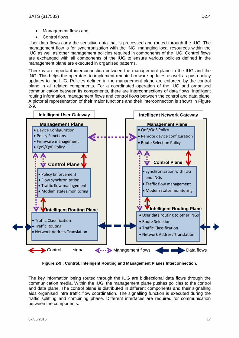
BATS (317533) D2.4
07/06/2013 17
Management flows and
Control flows
User data flows carry the sensitive data that is processed and routed through the IUG. The management flow is for synchronization with the ING, managing local resources within the IUG as well as other management policies required in components of the IUG. Control flows are exchanged with all components of the IUG to ensure various policies defined in the management plane are executed in organised patterns.
There is an important interconnection between the management plane in the IUG and the ING. This helps the operators to implement remote firmware updates as well as push policy updates to the IUG. Policies defined in the management plane are enforced by the control plane in all related components. For a coordinated operation of the IUG and organised communication between its components, there are interconnections of data flows, intelligent routing information, management flows and control flows between the control and data plane. A pictorial representation of their major functions and their interconnection is shown in Figure 2-9.
Figure 2-9 : Control, Intelligent Routing and Management Planes Interconnection.
The key information being routed through the IUG are bidirectional data flows through the communication media. Within the IUG, the management plane pushes policies to the control and data plane. The control plane is distributed in different components and their signalling aids organised intra traffic flow coordination. The signalling function is executed during the traffic splitting and combining phase. Different interfaces are required for communication between the components.
Control signal flows
Management flows Data flows
Management Plane
Control Plane
Device Configuration
Policy Functions
Firmware management
QoS/QoE Policy
Policy Enforcement
Flow synchronization
Traffic flow management
Modem states monitoring
Traffic Classification
Traffic Routing
Network Address Translation
Intelligent User Gateway Intelligent Network Gateway Gateway
Management Plane
Control Plane
Management Plane
QoE/QoS Policy
Remote device configuration
Route Selection Policy
Synchronisation with IUG
and INGs
Traffic flow management
Modem states monitoring
User data routing to other INGs
Route Selection
Traffic Classification
Network Address Translation
Intelligent Routing Plane Intelligent Routing Plane

BATS (317533) D2.4
07/06/2013 18
2.4 Definition of Interfaces between Functional Components For these various traffic flows, different interfaces are required in the respective components. We refer to a flow as a sequence of packets identified by source and a destination address, source and destination port, transport protocol (e.g. TCP/UDP) as well as the IP traffic class, which may allow associating a subset of packets in a multiplex with the specific sequence. Moreover, a flow is unidirectional, and bidirectional communication, such as a voice call, consists of two flows. Complex application might consist of multiple flows in each direction.
Two main categories of interfaces will be differentiated. These are external interfaces and internal interfaces. The internal interfaces as well as the specific protocols associated with flow of information between these interfaces will be specified in WP3.
A full description of both internal and external interfaces is depicted in the following diagram
(Figure 2-10, copied from D2.3 Figure 6-1) which shows the generic functions and
connections related to the IUG. This is provided to act as a reference for discussions relating
to data and control information flows and element functionality. It is expected that this
reference diagram will be reviewed and may be amended in later stages, for example in
WP3. In describing functional components, as in previous sections, the IUG is used as
reference as most modules carry out similar functions in both the IUG and ING. This diagram
is not intended to preclude any physical integration.
Figure 2-10 : BATS IUG Function Diagram
The types of interface and their functions are summarized below in Table 2-2: Interface summary., which is derived from section 6.2 of D2.3.
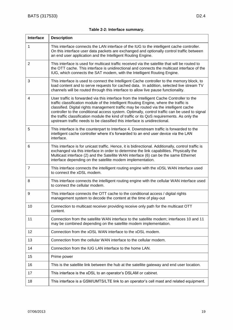
BATS (317533) D2.4
07/06/2013 19
Table 2-2: Interface summary.
Interface Description
1 This interface connects the LAN interface of the IUG to the intelligent cache controller. On this interface user data packets are exchanged and optionally control traffic between an end user application and the Intelligent Routing Engine.
2 This interface is used for multicast traffic received via the satellite that will be routed to the OTT cache. This interface is unidirectional and connects the multicast interface of the IUG, which connects the SAT modem, with the Intelligent Routing Engine.
3 This interface is used to connect the Intelligent Cache controller to the memory block, to load content and to serve requests for cached data. In addition, selected live stream TV channels will be routed through this interface to allow live pause functionality.
4 User traffic is forwarded via this interface from the Intelligent Cache Controller to the traffic classification module of the Intelligent Routing Engine, where the traffic is classified. Digital rights management traffic may be routed via the intelligent cache controller to the conditional access system. Optimally, control traffic can be used to signal the traffic classification module the kind of traffic or its QoS requirements. As only the upstream traffic needs to be classified this interface is unidirectional.
5 This interface is the counterpart to Interface 4. Downstream traffic is forwarded to the intelligent cache controller where it’s forwarded to an end user device via the LAN interface.
6 This interface is for unicast traffic. Hence, it is bidirectional. Additionally, control traffic is exchanged via this interface in order to determine the link capabilities. Physically the Multicast interface (2) and the Satellite WAN interface (6) can be the same Ethernet interface depending on the satellite modem implementation.
7 This interface connects the intelligent routing engine with the xDSL WAN interface used to connect the xDSL modem.
8 This interface connects the intelligent routing engine with the cellular WAN interface used to connect the cellular modem.
9 This interface connects the OTT cache to the conditional access / digital rights management system to decode the content at the time of play-out
10 Connection to multicast receiver providing receive only path for the multicast OTT content.
11 Connection from the satellite WAN interface to the satellite modem; interfaces 10 and 11 may be combined depending on the satellite modem implementation.
12 Connection from the xDSL WAN interface to the xDSL modem.
13 Connection from the cellular WAN interface to the cellular modem.
14 Connection from the IUG LAN interface to the home LAN.
15 Prime power
16 This is the satellite link between the hub at the satellite gateway and end user location.
17 This interface is the xDSL to an operator’s DSLAM or cabinet.
18 This interface is a GSM/UMTS/LTE link to an operator’s cell mast and related equipment.

BATS (317533) D2.4
07/06/2013 20
2.5 Specification of Protocols on Interfaces The protocols used at each interface of the IUG are summarized in Table 2-3 which is derived from section 6.2 of D2.3. It lists the protocols at each interface shown in Figure 2-10. This shows the interfaces for the three different levels of IUG integration. It should be noted that reference case is PIB so attention should be focussed on the partially integrated column.
Table 2-3: Interface protocols.
Interface Partially Integrated Fully Integrated Loosely integrated
1 Internal data bus carrying IPv6 traffic and control data
2 Internal data bus carrying IPv6 unidirectional multicast OTT traffic
3 Internal data bus carrying IPv6 multicast OTT traffic and DRM data
4 Internal data bus carrying IPv6 unidirectional traffic with any related QoS control traffic to the traffic classification in the intelligent routing engine
5 Internal data bus carrying IPv6 unidirectional traffic from the intelligent routing engine
6 Internal data bus carrying IPv6 bidirectional traffic between the intelligent routing engine and the satellite WAN interface
7 Internal data bus carrying IPv6 bidirectional traffic between the intelligent routing engine and the xDSL WAN interface
8 Internal data bus carrying IPv6 bidirectional traffic between the intelligent routing engine and the cellular WAN interface
9 Internal data bus carrying IPv6 DRM data
10 Either as in the fully integrated or loosely integrated options depending if satellite modem and/or receiver is integrated into the IUG
Internal data bus carrying IP v6 unidirectional multicast OTT traffic
Either
a) L band feed carrying IP Multicast traffic over DVB S2 with ACM or
b) Gig-E carrying IPv6 multicast traffic depending where the multicast receiver is located
11 Either as in the fully integrated or loosely integrated options depending if satellite modem is integrated into the IUG
Internal data bus carrying IPv6 bidirectional traffic and control information
Gig-E carrying IPv6 unicast traffic and control data
12 Either as in the fully integrated or loosely integrated options depending if xDSL modem is integrated into the IUG
Internal data bus carrying IPv6 bidirectional traffic and control information
Gig-E carrying IPv6 unicast traffic and control data
13 Either as in the fully integrated or loosely integrated options depending if cellular modem is integrated into
Internal data bus carrying IPv6 bidirectional traffic and control information
Either
a) Gig-E / 100bT carrying IP v6 unicast traffic
BATS (317533) D2.4
07/06/2013 21
Interface Partially Integrated Fully Integrated Loosely integrated
the IUG b) USB2+ carrying IPv6 unicast traffic (see D2.3 section 6.3.1)
14 External LAN interface to the IUG; may be
a) Ethernet (Gig-E, 1000bT, IEEE 802.3)
b) Wi-Fi (IEEE 802.11 – see D2.3 section 6.3.1.2)
c) Both a) and b)
15 External prime power connection – see D2.3 section 5.3.2 and Annex B.
16 As stated in D2.3 and elsewhere this will be;
a) DVB S2 or a successor in the forward direction for both unicast and multicast traffic
b) DVB RCS2 or a successor in the return direction for unicast traffic
17 xDSL – see D2.3 table 6-3
18 Cellular – see D2-3 table 6-4
2.5.1 Management Protocols in the IUG
In the management plane, there is a need to adhere and integrate a standard that facilitates
the BATS operator FCAPS management over the IUG. One of most advanced protocols to
do these operations is the TR-069 family of specifications defined by the Broadband Forum
that is depicted in the next figure with all the specifications delivered at this moment.
However, this is only an example, and other family of protocols such as the ones from the
3GPP can also be considered.

BATS (317533) D2.4
07/06/2013 22
Figure 2-11 TR-069 family of specifications defined by the Broadband Forum
A summary of key technical requirements specifications and associated protocols is mentioned below. A detailed description as well as their relevance to the BATS IUG and modules where applied will be provided in WP3. This is by no means an exhaustive list of technical requirements the BATS IUG conforms to.
TR-069 – CPE WAN Management Protocol [7]: provides the extensible, secure,
communications layer, while also providing basic gateway router and Wi-Fi
configuration and management functionality. The IUG may be configured remotely by
first obtaining the IP address of the ING for a pairing and further exchange of
configurations settings via the management plane. This specification includes various
generic auto-configuration requirements that will be relevant for the BATS IUG. These
include reconfiguration of services provided by the IUG, initial service provisioning
and transparent transmission of specific auto-configuration requirements from the
ING to the IUG.
TR-098 provides QoS functionality as well configuration profiles to ease management
and deployment.
TR-104 and TR-110 together specify remote VoIP device configuration and
management.
TR-106 and TR-111 together specify the remote management of devices on a LAN,
even those using the private IP space behind a NAT gateway.

BATS (317533) D2.4
07/06/2013 23
TR-131 specifies the ACS Northbound Interface.
TR-135 specifies the configuration and management of Set Top Boxes (STB). Note,
unless the STB is an edge device, TR-106 and TR-111 support will also be required.
TR-140 specifies the configuration and management of Network Attached Storage
(NAS).
TR-068 specifies requirements for Modems such as the requirements for WAN
Access protocol and LAN Physical interfaces.
TR-124 – Functional Requirements for Broadband Residential Gateway Devices [5]:
This technical requirement specifies general requirements for any residential gateway
such as the IUG that incorporates similar interfaces described in the previous section.
It also specifies generic LAN/WAN interface modules that can be used as a reference
for the BATS IUG implementation. The requirements for optional modules enabling
different types of physical broadband interfaces (Satellite, 3G/4G or DSL) are
specified in this specification.
TR-196 – Femto Access Point Service Data Model [8]: For the IUG to support
capability as a Femtocell, this specification defines the data model for its remote
management. The Femtocell may be integrated into the IUG or could be attached
using either the satellite or xDSL as backhaul to the mobile network. Further
discussions on the feasibility of this functionality within the scope of the BATS project
will be discussed in WP3.2.

BATS (317533) D2.4
07/06/2013 24
Intentionally blank

BATS (317533) D2.4
07/06/2013 25
3 Key Challenges and Solutions with Selected IUG Scenarios
In this chapter we provide an analysis of the technical issues implied in the selected integration scenarios. Based on the definitions and descriptions provided in the previous chapter, we address the integration issues themselves as far as the IUG/ING architecture is concerned in Section 3.1. In Section 3.2 we address the challenges for the integration of the different networks with a BATS operator and in Section 3.3 the end user system integration challenges are identified. In Section 3.4, we address the research challenges faced by the satellite network as a result of the integration on the IUG/ING and the interaction among both units.
3.1 IUG Integration
3.1.1 CPE- integration of IUG with modems
The following three two-way modem types apply for the IUG in the BATS network:
SatCom
LTE/3G Cellular
xDSL
In addition, there is a satellite multicast receiver connected to the IUG core. This multicast receiver may or may not be integrated with the broadband SatCom modem. Figure 3-1 shows the HbbTV initiative, and is a solution where the satellite broadband and satellite multicast share the same communication platform. With this level of integration, it may be feasible to have a common satellite modem. With the current DTH satellite broadcast that is not using IP for the multicast it will be necessary to have a separate satellite receiver, respectively one for the satellite multicast and one for the broadband two-way SatCom.
Figure 3-1: Hbb solution to integrate broadcast and multicast
Particularly LTE/3G modems but also xDSL modems have standardised interfaces that usually interoperate well with different implementations of the network infrastructure. This is true for the user plane and the control plane, and at least partly for the management plane, Satellite DTH multicast receivers are also standard, but for these there may also be compatibility issues within the management plane that need to be considered.
However, the SatCom VSAT modems are currently not subject to sufficiently interoperable standardisation of the satellite interface, and thus we can assume that the user modem in a VSAT network is of the same brand as the VSAT hub. Evolution of an open VSAT
BATS (317533) D2.4
07/06/2013 26
specification as specified in DVB-RCS2 may eventually overcome this restriction, but this will require completion of this standard in the management plane to complement user plane and control plane and will need market acceptance.
Bonding of multi-links implemented over the different network types, including satellite, is considered insufficient as a general solution, as it will result in an unnecessary delay for the traffic passed via the terrestrial networks in order to align it with the data transported over the satellite link. But this method may allow maximizing throughput by simultaneously exploiting the multiplicity of access networks.
The IUG user is assumed to have one single BATS subscription and is connected to the Internet via the different physical networks:
A SatCom VSAT subscription including satellite multicast.
An LTE/3G Cellular subscription, and/or
An xDSL subscription
The BATS service specification for the IUG user is assumed to be a result of merging the features of the two-three listed subscriptions, utilising the features of the IUG and ING.
The BATS operator is assumed to operate the ING and to act at least as a VNO for the three physical networks (satellite, LTE/3G and xDSL). It is assumed that the ING connects to concentrators in the different physical networks probably tunnelling the user traffic. It is required that each network operator offers sufficient interfacing for the BATS operator, in the user plane and the control plane and as well as in the management plane.
The BATS operator could be more tightly integrated with the SatCom operator and satellite broadcaster than for the LTE/3G and xDSL operators, as the latter networks may need to share local physical resources with non-BATS subscribers under control of the particular network operator. Satellite networks have a larger coverage area, and it may be possible to achieve sufficient user traffic aggregation for sharing of the physical resources by serving BATS users alone.
It is possible to get LTE/3G cellular modem components and xDSL modem components for full integration with the IUG. The SatCom modem could fully integrated with the IUG by tailoring the integration to a specific SatCom network implementation.
The BATS operator must be able to get enough information from the access networks to set the configuration of the ING and IUG appropriately in options where both are present. Both the IUG and the BATS central network controller (ING) will need to know the status of a particular modem and its network connection.
3.1.2 IUG Integration for the PIB architecture
The PIB architecture as depicted in D2.3 may be implemented as an integration of the IUG core and the SatCom modem, connecting with an external LTE/3G modem and an external xDSL modem. This integration can be a feasible first step to integration when implementing the IUG core in parallel with implementing also a SatCom system or a terminal for a particular SatCom system. One solution could be that the IUG uses management protocols to pull information from the external modems that are utilized to take forwarding decisions. In this case, the IUG can feed status reports back to the BATS operator. In this way, the IUG can be adapted to different implementations of modems. This can also be a useful architecture when the BATS operator is a VNO in the physical terrestrial network and may have insufficient access to terrestrial network status per user site. The IUG may constitute a single point for collection of consolidated networking status for the particular user site, and it may be simpler for the BATS operator to collect information from the IUG instead of collecting this from a multitude of physical networks. A possible downside is that there can be some more latency connected with pulling the information from the IUG, and possibly also
BATS (317533) D2.4
07/06/2013 27
connectivity issues. Also there is an overhead attached to the management traffic on the user link.
Alternatively, a CPE with integrated IUG, LTE/3G modem and xDSL modem may hook up with different implementations of SatCom VSAT modems through use of an interface implemented by the SatCom modem. Similarly, a solution can be that the IUG uses standardised management protocols supported via IP to pull information from the SatCom modem that is utilized to take forwarding decisions. The IUG can possibly feed status reports to the BATS operator. In this way, the IUG can adapt to different implementations of SatCom modems. This can also be a useful architecture when the BATS operator is a VNO in the physical SatCom network and may have insufficient access to network status per user site. The IUG may constitute a single point for collection of consolidated networking status for the particular user site, and it may be simpler for the BATS controller to collect information from the IUG instead of collecting this from a multitude of physical networks Downsides are as above.
The BATS operator could be different from SatCom network operator, and act as VNO also in the SatCom network, as assumed applicable also in LTE/3G and xDSL networks. The SatCom network must then provide enough information for the BATS operator to take proper forwarding decisions and configure the ING accordingly.
If the interface between SatCom modem and IUG is external, it must be possible to pull enough information from the external SatCom modem for the IUG to take correct forwarding decisions.
There is also a satellite multicast receiver in conjunction with the IUG. For MPEG-TS based multicast traffic this can be a receiver integrated with the IUG, even if the SatCom modem is external. IP based multicast traffic could be passed from the SatCom modem to the IUG and would then not need a separate interface.
3.1.3 IUG integration for the FIB architecture
In the FIB architecture the SatCom modem is fully integrated with the IUG. This can for example take the form of an integration of standard LTE/3G and xDSL components with a SatCom VSAT modem that fits with a particular brand of SatCom VSAT hub. The assumptions are:
SatCom VSAT network coverage with the particular brand of hub that connects with
the particular brand of SatCom VSAT modem
The LTE modem and the xDSL modem are assumed compatible with most of the
common network infrastructure
This solution may be particularly attractive when the BATS operator is also the SatCom VSAT network operator, since the CPE will have to connect with a particular brand of SatCom hub.
All modem/IUG interfaces are internal. For the IUG core, it must be possible to pull enough information from each internal modem to take correct forwarding decisions and to give correct status indications to the BATS operator. It is assumed that this information could come e.g. from a modem virtualized in an embedded CPE processing system shared by all the modems and as well the IUG core.
If the satellite multicast receiver is integrated as well, the interface from the satellite LNB to the IUG can be an L-band coax that is shared between the satellite multicast receiver and the SatCom modem. If the satellite multicast is in MPEG-TS format with CA this is handled by a separate receiver. If the satellite multicast is carried over IP this is handled by the receiver within the SatCom modem.

BATS (317533) D2.4
07/06/2013 28
3.1.4 Integration Issues and challenges
Use of a shared interface for satellite multicast and broadband two-way SatCom (as
for HbbTV )
Remote management of CPE, modems and satellite multicast receiver
o This is likely to be implementation specific for the SatCom VSAT modem but
should aim at an interface standard if possible
o It could be implementation specific for the satellite multicast receiver if no
standards exist.
o For the xDSL modem or is TR-069 compatibility may be sufficient
o A generic management for the LTE/3G modem is desirable
Traffic Identification and prioritisation, including the determination of the QoE
requirements from observing the data flow (see section 3.3.4)
Flow recognition and treatment with respect to making forwarding path decisions
o Association of a flow to a policy
o Association of a packet to a flow
o Interrelation policies for flows with differentiated QoS / QoE requirements
Management of BATS system configuration to ensure that a fault in one ING does not
cause any IUG to lose service.
The above issues will be addressed in WP3.
3.2 Operator Integration In the D2.3, various integration scenarios were studied and it was concluded that an integrated operator is the most feasible solution for the BATS project. In this section, challenges of operator integration as well as important issues that must be taken into account by the operator are provided.
When one operator physically owns the three different networks, challenges to be overcome are rather easy. Real challenges emerge when one operator rents other operators’ or infrastructure providers’ networks and provides an integrated Internet service to the end user. In this section the latter case is assumed.
The accounting and billing problem is one of the major concerns of the integrated Internet service provider. The integrated operator has different SLA’s with different infrastructure providers, and these SLA’s can be based on bandwidth allocation as well as on data traffic in case the infrastructure has a limited bandwidth (e.g. cellular networks). Therefore, the operator needs to optimize the accounting and billing such that both the infrastructure providers and the end users are satisfied. Optimization of the billing may not always be sufficient to survive financially. In this case, the operator can also require tuning the connections of the end user. The operator may have to decrease one type of connection’s bandwidth so that the end user (and the operator) does not have a huge bill at the end of the month.
As mentioned earlier, the operator will have different SLA’s with different kinds of infrastructure providers. In the case of the fixed DSL network, infrastructure providers usually allocate a certain amount of bandwidth to the operator. However, for cellular networks this is highly impracticable due to limited bandwidth of such networks. This however varies in different countries as in the UK for example, data from cellular operators are usually offered at a pre-set cost up to an allowed cap on volume of data used.
In case of underperforming network conditions, the integrated operator will be responsible to end users. As it is desired for the heterogeneity of communication links to be invisible to end users, it is the operator’s job to find out which of the three infrastructure providers do not meet their SLA obligations. This process can be problematic because the fixed, cellular and satellite connections have different architectures as well as different behaviour. For example,

BATS (317533) D2.4
07/06/2013 29
the underperformance of the satellite connection may be temporary and due to weather conditions, whereas the fixed connection can be underperforming due to some roadwork in the neighbourhood. The operator may need to monitor the three networks to find out the problem, and due to different architectures these three connections will require slightly different monitoring techniques.
The OAM (Operations, Administration and Management) also poses a challenge to the operator which provides integrated Internet services. The integration of different access technologies could result in an unmanageable complexity. For the operator to manage them easily, it should have access to the infrastructures of these access technologies. In case of fixed DSL network, this is achieved by allocating a Virtual Network (VN) to the operator. This is called network virtualization, by which the operator has the access to the infrastructure at the network layer (and above) and can operate the allocated network as its own. A similar allocation should be made with the other two access technologies so that the operator does not depend on the infrastructure provider for the OAM (which makes the OAM overly complicated).
Regulatory issues are also challenging for an integrated Internet service provider. Different governments have different regulations for transactions such as network virtualization as well as for cellular operators, satellite operators and DSL operators. The operator will need to satisfy all these regulatory requirements for different countries. In addition, the state of three access technologies may also differ from one country to the other. Therefore, modifications may be needed in the business model for some countries.
3.3 End user system integration This section provides a brief overview of how the end user systems at the home are connected to the BATS network through the Intelligent User Gateway (IUG). Furthermore, this section describes the monitoring and provision of Quality of Experience (QoE) to the end users at the home front.
3.3.1 Integration of home network and devices with the IUG
The IUG is the main interface between different access networks such as xDSL, Satellite and LTE and the home network. This subsection describes different protocols and standards that are related to connecting broadband devices to the IUG.
The standards and protocols related to connectivity to the IUG are mainly divided in to wireless and wired access methods. A typical home networking setup is displayed in Figure 3-2a. In the context of the BATS project, some of the functions of the fixed/mobile/satellite connections will be integrated in the IUG, as defined in the baseline integration scenario (PIB). From the LAN side, the IUG may be connected to the home gateway or a WiFi router through an Ethernet cable as shown in Figure 3-2b; or alternatively, another possibility is to have a WiFi router embedded in the IUG. Since standards related to wireless technology are evolving rapidly, it was recommended in section 6.3 and 9.2 of Deliverable 2.3 to have the WiFi router connected externally to the IUG.

BATS (317533) D2.4
07/06/2013 30
Figure 3-2a: A simple home network [1]
Figure 3.2b: Corresponding BATS home Network (one possibility)
3.3.1.1 Wired home networking standards Wired home networking requires all devices to be connected with Ethernet cables to the IUG. This is a good option if the equipment is near the IUG. For the devices to be connected to the IUG in this manner, the devices need to be equipped with an Ethernet port. Thus smartphones and tablets would not be able to connect to the IUG with Ethernet connections. Other devices (e.g. Nintendo Wii) may require an additional Ethernet adaptor to be connected in this way [2]. Ethernet is formally known as the IEEE 802.3 family of standards and utilises the Carrier sense multiple access with collision detection technology.
In addition to the Ethernet standard, the American National Standards institute (ANSI) standardised the Fibre Distributed Data Interface (FDDI) for data distribution over fibre optic lines in a local area network. The standard can achieve 100Mbps (Max 200Mbps), which is equivalent to the Ethernet standards. However, Ethernet connections are often cheaper than the fibre connections.

BATS (317533) D2.4
07/06/2013 31
Furthermore, certain devices have the USB connection type. However, there are USB to Ethernet, and Ethernet to USB adapters available commercially.
The advantage of wired connections is its reliability and speed, whilst it is often a difficult task to run Ethernet cables all over the home space. This can be offset by the use of power-line adaptors to run the Ethernet data over the home’s domestic power cabling.
The IUG design should consider including at least an Ethernet port for the devices to be connected. Whilst also having an USB connection port is ideal it is not essential as a customer could easily find a USB to Ethernet adapters from the market. It should be noted that the Ethernet connection is the most straightforward method of connection from the IUG to the home gateway or the WiFi Router.
3.3.1.2 Wireless home networking standards Wireless connections allow the devices to be connected via Wi-Fi, which is suitable for smartphones, tablets and also for laptops and many games consoles. Wireless connections have the luxury of connecting many devices without running cables [2]. A wireless network will require a central access point, and in the context of the BATS project the IUG is expected act as the access point.
The most popular wireless technology is the IEEE 802.11 family of standards, which is commonly known under the name of Wireless-Fidelity (Wi-Fi). The current WiFi standards can achieve bandwidths of up to 867Mbps. The most common WiFi standard at the moment is 802.11n which can achieve a bandwidth of 150Mbps. For more information on WiFi standards readers are referred to Deliverable 2.3.
The IUG design may include wireless connectivity to connect wireless devices and including a chipset to adhere to WiFi standards is quite important. However, given the context that IUG is not in place to replace the home gateway or a WiFi router that is usually provided by the service provider, it is not essential to include a WiFi connectivity in the IUG.
In the following subsections we introduce the methods of monitoring and provision of QoE on end user systems that are connected to the IUG that have been identified until this stage.
3.3.2 Traffic Identification
Different traffic identification schemes are identified in section 3.6 of Deliverable 2.3. For the sake of completeness that information is summarized here. In the research area of traffic identification and classification a lot of work has already been done. Very simple and easy to implement methods as well as very complex approaches have been discussed for a long-time. Several authors e.g. [9] and [10], provide taxonomy and a comparison of different classification methods and techniques. Usually all traffic classification techniques can be assigned to four main categories which inspects the traffic and a fifth category where the application provides the necessary information: Method 1. A simple identification method based on the ports used by the application; Method 2. A payload-based method which classifies traffic by analysing the headers and
the payload of packets; Method 3. A host-based approach, which identifies traffic by patterns of host behaviour Method 4. Classification methods which use machine learning techniques to assign traffic
to application types; Method 5. A fifth technique is now being developed whereby the application provides
specific metadata (within the header) that indicates QoE requirements to the routing engine

BATS (317533) D2.4
07/06/2013 32
3.3.3 Mapping the traffic identification schemes to the IUG architecture
The IUG and ING architecture should enable each of the QoE requirement capture techniques identified above to be implemented and evaluated. The modules and connectivity to include all these methods are shown in
Figure 3-3 shows the user application with a vertical double-headed arrow (pink) representing the Application Data-flow Units (ADUs). The approximate mapping to the 7 layer OSI model is shown at the right hand side. In the bottom half of the figure the ADUs arrow passes between two possible communications system technologies, as examples (others will exist). Each of these communications systems passes back its current capabilities to the “Intelligent Routing Engine” (yellow arrows).
A separate (yellow) arrow “App QoE Requirements” is shown direct from the User Application to the “Intelligent Routing Engine” function (as in Method 5). Typically the QoE information would be extracted from the header or from Deep Packet Inspection as in Method 2. So this might be collected using the Data Analysis block. Method 3 and 4 would also be supported by the Data Analysis block. Considering each method for determining QoE requirements:
Method 1 could use the destination IP Address or port. This address can be checked using the remote “IP Address to QoE Translate” function (located at the ING) to determine the required QoE. This information can then be cached locally to minimise the need to access the remote server. Alternatively, the local device’s IP or MAC address could be translated into QoE requirements using pre-loaded information in the “Pre-set rules for routing”. This would require the IUG system to be configured such that when a new device is added to the local network, the user must select the type of system being attached, so that QoE rules could be determined. The “Pre-set
Figure 3-3: Architecture needed to accommodate the five methods for QoE determination and the Intelligent Routing Engine.

BATS (317533) D2.4
07/06/2013 33
rules.” function would also allow restrictions to be placed on the ability of different applications (or users) to access the higher cost networks to prevent unexpected bills for telecoms use.
Method 2 would use Deep Packet Inspection (DPI) to understand the nature of the application and the QoE requirements for the data. Again, if the application is not recognised, then a remote database would need to be accessed to obtain information on the QoE requirement (similar to method 1). DPI would be unlikely to deliver any benefit on a packet by packet basis, but may be effective for dataflows. There are likely many proprietary protocols that the IUG would be unable to classify accurately, but it might be able to access reference data from a central look-up table maintained at the ING.
Method 3 (study of traffic patterns and host behaviour) would be possible once it
becomes obvious that a large volume of data packets are being handled and future
dataflows of this type could perhaps be re-routed during the download. There would
be an initial phase where the dataflow may be routed sub-optimally.
Method 4 (machine learning) might also be possible, but the required processing
within the IUG would be power hungry, adding to system cost and to the energy used
by the IUG. However, for specific applications, such as gaming, the switch to the
actual gaming phase will be easy to detect -assuming that there will be a significant
change in different packet size, different packet rate, for the different phase of the
game.
Method 5 should work reliably, for those applications that have been designed to
produce the QoE requirement metadata. This scheme is still being developed,
primarily by the Cooperative Intelligent Transport Systems community.
We also need to determine whether there are any other methods to be considered – based on current best practice, R&D projects and standardisation work.
3.3.4 QoE requirements for BATS use cases
The uses cases/service elements and their uses cases identified in D2.3 are:
Conversational voice and video (for video conference and HD VoIP)
Streaming audio and video (for HDTV streaming)
Command/control applications (for interactive gaming)
Messaging/Text communications (for social media and instant messaging)
Considering the types of systems that might be connected and the applications that might be used:
For a TV set-top box that only supports iPlayer and equivalent services, the data-flows will have a high volume and are jitter and latency intolerant. The QoE requirements for such a device will be fixed, so all that is necessary is to recognise the device and hence the service that is using the IUG. The QoE requirements for that service will be known by the IUG.
Method 1 could use the source IP address (or MAC address) for the local device and translate in a locally held look-up table to determine the QoE requirements for that device. Alternatively the IUG could use the destination port information to determine the service being used and the QoE requirements for that service. In general, the IUG would need to access a remotely held look-up table to determine the service being used and therefore the QoE required.
Similarly smart meters and some IoT white goods will have limited functionality with well-defined QoE requirements that can be immediately determined from their identity.
BATS (317533) D2.4
07/06/2013 34
PCs and tablets support a wide range of applications. So it is necessary to understand the needs of the applications. For example, an email service such as Microsoft Outlook tolerates delay, and may involve medium data volumes. In practice, Outlook will only connect to a limited (predefined) range of service providers, so the destination IP address / port of the service provider could be used to recognise the nature of the dataflow and hence its QoE requirements. However, if Outlook is provided as one of a range of services from that server port / IP address, then it would not be possible to determine the application being used from the IP address: deeper investigation of the dataflow would be needed.
Method 2 allows deep packet inspection (DPI) to determine the transport layer payload, i.e. the actual user data. Assuming that the classification engine can recognise the protocols correctly, this would allow very accurate classification. However, scalability and privacy are issues here.
Another example are VoIP applications which require very low latency. For example, Skype uses peer to peer communication which makes it impossible to detect the use of VoIP simply from the port addresses. DPI (method 2) would be required in this case to recognise the use of the Skype application.
Gaming is implemented in three phases: the download and installation of the game; the download of the specific game environment and the playing phase. Whilst the playing phase needs very low latency for the movement and scene change information, the amount of information transmitted can be minimised by sending vectors that manipulate avatars and the background. In contrast, the initial installation of the game and downloading of the game environment requires the transfer of large volumes of data, but without latency restrictions. It should be possible for the application to add a simple metadata message to indicate the QoE requirements for these different data-flows (method 5). But how would we support an application that does not provide metadata? Methods 3 and 4 may be suitable, but would need careful evaluation.
3.3.5 Recommended Approach to QoE Determination
It is apparent that a combination of different methods for the QoE determination will be needed in order to support a wide range of applications. The different methods have different levels of maturity. Each of these methods can be implemented and evaluated independently.
Methods 1 and 2 should be easy to implement in a demonstrator. However, we would need to provide a central server (possibly as part of the ING) which the IUG can access in order to determine whether there was a specific service with a defined QoE requirement at a particular IP address (similar to DNS!).
The use of methods 1 and 2 enables the allocation of optimal routing strategies to a useful percentage of the total data flows through the IUG. However, the ability to optimize the routing of data-flows would be significantly increased by the adoption of the Methods 3, 4 and 5.
Methods 3, 4 and 5 are immature and need further development within the BATS team. There is important innovation in the use of Methods 3, 4 & 5. At this stage it is difficult to say how effective those methods are. It is also unclear what rate of adoption there would be for inclusion of method 5 metadata information by most common applications.
Method 5 is currently under development within several C-ITS Framework projects, and is being standardised in CEN TC278 WG16 (in conjunction with SO TC204 WG18). The BATS project has been presented to that body, and they would welcome the creation of Project Liaison Agreement between TC278 and BATS.
Project Liaison Agreements are strongly encouraged by the European Commission as a means to create stronger coupling between the Framework projects and the ESOs (European Standardisation Organisations). There are additional benefits from this relationship. The Project Manager of Framework project ITSSv6 has stated that he would be willing to give BATS free use of any protocol stacks that they have developed in their project.

BATS (317533) D2.4
07/06/2013 35
(ITSSv6 is promoting the use of IPv6 in Intelligent Transport Systems.) CAL is in a strong position to work with the standards community and the connection to related project activity, but would not be able to develop software for BATS that makes use of the C-ITS standards. Further information on the current activity to develop and standardise method 5 can be found in section 4.4 and Annex A of D2.3.
In practice it is likely that the BATS would need to support most (if not all) of these QoE determination techniques.
Note that if any of these methods fails to deliver the expected benefits, this will not affect the ability of the BATS IUG to deliver the benefits from the methods that are proved to work. So there is little additional risk in implementing and evaluating each of these methods.
3.4 Research Challenges in the satellite network design for FIB/PIB This section addresses the impact of the IUG choices on the satellite network design. As far as the network is concerned there seems no difference between the choices of the FIB and the PIB scenario. The major identified issues are:
Dealing with the multicast at the terminal and the gateway.
At the terminal it is a choice between separate receiver chains (multicast and broadband) or an integrated approach. This would need to be reflected at the Gateway.
Use of a shared interface for satellite multicast and broadband two-way SatCom
(as for HbbTV).
Use of a shared antenna for satellite multicast reception and broadband two-way
SatCom (likely a necessity for any scenario for cost reasons and to achieve user
acceptance).
This topic will be addressed in detail in SWP3.3.
Dealing with multicast ACM:
Consider the algorithm necessary to implement ACM on the multicast data streams using signal quality data from the unicast links to the sites receiving each multicast data stream (one such per spot). Calculations of capacity gain will be needed, along with the implications for the cache refill management.
This topic will be addressed in the framework of WP4.
Compatibility between the satellite modem in the terminal and the gateway:
This relates principally to current incompatibilities between manufacturers equipment due to the lack of standardisation on the control and management planes. RCS2 is designed to solve this problem and provide a fully defined IP infrastructure. The question is whether it will in fact be accepted commercially and allows any manufacturers terminals to work with any gateway. If the satellite modem is not integrated then the issue becomes more about interfacing the service and control planes between IUG and Sat Modem.
This issue will be considered when planning the demonstration trials in WP6.
BATS operator integration of the IUG:
It is important to consider the optimum location of the ING with respect to the location of the satellite hub. Issues such as configuration control, protocols such as TR-069 and SNMP need to be considered (covered earlier in Section 2). In addition, a re-association of an IUG with an alternative ING will be needed if there is a fault on the ING that is normally used.
BATS (317533) D2.4
07/06/2013 36
This topic will be addressed in detail in SWP3.1.
Location of PEP with potentially bonded/tunnelled traffic
Typically the satellite PEP is provided internally to the satellite modem/gateway system. If the traffic is tunnelled in some way then either the PEP in the modem will need to work within the tunnel, or the IUG/ING will need to incorporate their own PEP. PEP in this context also includes header compression and web acceleration.
This topic will be addressed in detail in SWP3.2.
How the hub can inform ING of link state
In order for the ING to make intelligent routing decisions, it needs to know the current loading of the forward link and the status of the connection to each remote location including parameters such as modulation & coding, latency, backlog and Fair Access Policy (FAP) state. This information can be obtained by querying the IUG. It will be addressed in detail in SWP3.3 and SWP3.5.
How the VSAT can inform the IUG of link state
In order for the IUG to make intelligent routing decisions it needs to know the current loading of the return link including parameters such as modulation & coding, latency, jitter, backlog and FAP state.
This topic will be addressed in detail in SWP3.3 and SWP3.5.
How will the VSAT switch to idle state to save power and what the IUG needs to know about this:
The majority of the VSAT power is used by the transmitter, to reduce the carbon footprint the VSAT should switch to an idle state consuming less power. There will be a finite re-start duration and the IUG should be aware of this duration and transmit state to maximise the end user QoE.
This topic will be addressed in detail in SWP3.4.
Dynamic switching between unicast and multicast transmissions:
This is a cache controller issue but will impact the space segment capacity load.
This topic will be addressed in detail in SWP3.3.
Synchronisation issues:
How will the interrelated traffic flows sent via the satellite synchronise with other traffic flows sent via xDSL/Cellular in the IUG and ING.
This topic will be addressed in detail in SWP3.3.

BATS (317533) D2.4
07/06/2013 37
Challenges particular for remote maintenance of CPE, considering the following aspects:
This is implementation specific for the SatCom VSAT modem and the satellite multicast
receiver as well as the xDSL modem but generic for the LTE/3G modem. It needs to be
viewed as a specific element of the IUG implementation.
This topic will be addressed in SWP 3.5.
The following table specifies the level of complexity of some of the research challenges depending on the integration scenario considered in the IUG.
Table 3-1: R&D challenges with level of complexity depending on scenario.
FIB PIB (sat modem integrated)
PIB (sat modem not integrated)
Location of PEP with potentially bonded/tunnelled traffic
MED MED HIGH
How the VSAT can inform the IUG of link state
MED MED HIGH
How will the VSAT switch to idle state to save power and what the IUG needs to
know about this LOW LOW MED

BATS (317533) D2.4
07/06/2013 38
Intentionally blank

BATS (317533) D2.4
07/06/2013 39
4 IUG Prototype Supplier Selection
This section includes all information relevant to the second step of the IUG supplier selection process (beauty contest). In D2.3, approximately twenty companies were identified as potential suppliers of the IUG prototypes for the lab/field trials, out of which seven were considered as the best candidates. These potential IUG supplier/developers have been contacted and asked for more information in order to better assess their suitability for that task. These candidates need to be re-evaluated and down-selected to 2-3 final candidates, which will be then invited to submit a proposal to participate in the BATS project as developers of the IUG prototypes. This section is organised as follows: Section 4.1 summarizes the first step of the selection process carried out during WP2.3 in which the seven potential partners were selected. Section 4.2 summarizes the relevant information obtained during the “Beauty contest and re-evaluates the candidates in order to down-select the final set of two/three (detailed information is included in Annex A -). Finally Section 4.3 gives some information on the process that will be followed in the next and final step.
4.1 Summary of IUG supplier selection process and current status In order to develop the BATS IUG prototypes for the lab/field trials, the team designed a selection process as illustrated in Figure 4-1. Such process will finalise by the end of May with the selection of one company which will develop the prototypes based on one of the following options:
A single company that has all the identified skills who could be subcontracted by the consortium to develop the IUG.
A single company that has all the identified skills who would be managed by a consortium member to develop the IUG.
One of the consortium members can identify suitable, available products that they can integrate.
In any case, the final choice should be capable of:
Designing and integrating the IUG functionality in one or more boxes (fully/partial integrated IUG), in line with the BATS consortium identified requirements.
Approximately twenty companies were identified as having relevant experience for carrying out such a task. These companies were analysed based on their information available online (inspection process). After this initial step, it was clear that there is no one company that could directly supply the envisaged IUG without further development and integration work to adapt their existing products to the project’s needs.

BATS (317533) D2.4
07/06/2013 40
InspectionInspection Beauty contest
Beauty contest ProposalProposal SelectionSelection
~27 Companies ~7 Companies ~3 Companies 1 Company
WP2.3 WP2.4
Figure 4-1: IUG supplier selection process.
The different options were compared based on a set of weighted criteria in order to down select from the potential candidates, the 7 preferred options. The multiple criteria for the decision making were the following:
Location within the EU27 + Norway & Turkey Group;
Knowledge of satellite data channels / availability of their products to integrate or be connected to a satellite modem;
Knowledge of DSL data channels / availability of their products to integrate or be connected to a DSL modem;
Knowledge of 3G/LTE data channels / availability of their products to integrate or be connected to a 3G/LTE modem.
Knowledge of bonding techniques;
Knowledge of load balancing techniques;
Knowledge of other route selection techniques;
Experience of caching techniques including DRM;
Ability to integrate the functions (looking towards an IUG in a single box);
Familiarity with consumer markets;
Willingness of Consortium to work with the company (i.e., suitability);
Monitoring/Management capabilities of the device.
Based on the weighted decision matrix as shown in Table 4-2, 7 preferred candidates were identified. The list of candidates which were selected to be considered in the next step is provided in Table 4-1. Note that this ranking does not mean priority.

BATS (317533) D2.4
07/06/2013 41
Table 4-1: IUG options for lab/field trials (Top 7 candidates).
Ranking Company name
1 Fraunhofer-Wiback
2 Xrio
3 Viprinet
4 OneAccess/UDCast
5 Firebrick
6 Forsway
7 Shareband
During the next step, these companies have been contacted and invited to provide more information about their expertise in order to allow us to be in a better position to down select three final candidates. The information compiled from the “Beauty contest” is provided in section 4.2. The final candidates will be assessed individually in order to study ways to enrol them to the BATS project and they will be invited to submit a formal proposal for the IUG prototype development. Finally, a single candidate will be selected.

BATS (317533) D2.4
07/06/2013 42
Table 4-2: Selection table.
All
EU
FH &
Wib
ack
15
.86
.86
.34
.05
.06
.06
.82
.86
.58
.86
.07
14
71
4
Xri
o1
8.0
8.0
4.0
7.3
8.5
8.5
5.3
3.5
6.3
6.3
7.3
67
26
72
Vip
rin
et
17
.87
.86
.35
.08
.88
.07
.52
.88
.04
.51
.56
59
65
9
On
eA
cce
ss/U
DC
ast
17
.88
.05
.07
.35
.57
.06
.04
.35
.86
.56
.56
51
65
1
Fire
bri
ck1
7.8
7.8
4.8
5.8
9.0
7.0
5.0
2.8
6.3
6.0
6.5
64
86
48
Fors
way
16
.08
.08
.07
.33
.03
.05
.05
.88
.06
.87
.56
44
64
4
Shar
ed
ban
d1
6.0
6.0
4.5
7.0
8.5
8.5
3.0
3.0
6.3
6.5
6.5
63
56
35
Dra
yte
k1
8.0
8.0
4.0
6.8
4.3
7.8
5.5
2.8
6.0
5.5
3.8
59
75
97
Ava
nti
/Bu
ffal
o1
5.5
5.5
6.0
6.5
2.8
2.8
4.3
5.8
5.0
5.5
6.5
50
85
08
Tria
gno
sys
13
.57
.08
.04
.32
.82
.82
.82
.85
.55
.85
.85
01
50
1
Dre
am M
ult
imed
ia1
5.8
2.8
6.8
7.3
2.8
2.8
2.8
7.8
5.3
5.0
5.0
47
74
77
Bu
bb
lep
ho
ne
1
3.5
3.5
3.5
2.8
2.8
2.8
7.3
2.8
4.3
5.5
5.0
46
74
67
21
Ne
t1
2.0
6.3
6.5
2.8
3.0
3.3
2.8
2.8
3.8
5.5
3.8
44
54
45
Ico
mer
a1
1.8
7.8
1.8
4.3
2.5
2.3
5.0
2.8
2.5
6.0
4.8
43
74
37
Pe
plin
k/P
ep
wav
e8
.08
.03
.55
.87
.08
.06
.52
.86
.35
.33
.86
22
0
Pat
ton
8.3
8.3
4.0
2.8
8.0
8.0
6.5
2.8
6.3
5.0
4.0
62
00
Mu
shro
om
Ne
two
rks
8.0
8.0
3.5
2.8
8.8
8.8
7.3
2.8
6.0
4.5
3.5
61
20
Dig
i8
.08
.02
.85
.02
.32
.37
.32
.86
.05
.03
.55
23
0
Bu
ffal
o7
.87
.04
.87
.32
.52
.54
.05
.85
.04
.54
.34
81
0
Vu
+ (C
eru
)4
.31
.86
.57
.31
.81
.83
.08
.06
.84
.83
.04
61
0
Sap
ido
8.0
7.5
3.8
7.3
1.8
1.8
3.5
5.8
4.8
4.3
3.3
44
90
Weighting
6.0
6.0
6.0
2.5
8.8
8.0
10.3
3.8
15.5
18.3
15.0
Bu
sin
ess
suit
abili
Mea
n W
eig
hte
d
Tota
l We
igh
ts
100
Bo
nd
ing
Load
bal
anci
n
Oth
er
rou
te
Cac
he
Inte
grat
i
on
Mo
nit
or
ing
Co
nsu
m
er
Co
mp
any
EU2
7+T
+N
(1=Y
es)
DSL
3G
/4G
Sate
llite

BATS (317533) D2.4
07/06/2013 43
4.2 Beauty Contest and Down-selection During the selection process’ second step, called “Beauty Contest”, the seven candidates selected from the weighted table shown in the previous page were contacted. Out of these seven candidates, only four responded positively and showed a great interest in the BATS project. Hence, further information for the down selection process was received only from the following four companies:
Fraunhofer-Fokus
Xrio
One Access
Forsway
All candidates were asked to complete a questionnaire and provide relevant evidence to demonstrate that they have the expertise to accomplish the IUG development task. Such information is provided in Annex A -
As aforementioned, out of the 7 candidates selected in WP2.3 only 4 have been finally considered. Based on the new information captured during the “Beauty contest”, and summarized in Table 4-3, the four candidates have been re-scored following the same method and criteria as in WP2.3 (detailed as well in Chapter 4.1). Up to five partners from the BATS consortium have contributed to the step and have re-scored the candidates against the different criteria. The final scores are the average of all contributions. Note that, in this step, the weights of the different criteria parameters were maintained as those considered in WP2.3 (only the scores have changed). The final scoring table is shown in Table 4-4.
As a result of this second step, the final three candidates for taking over the development of the IUG prototypes are:
One Access
Xrio
Fraunhofer-Fokus
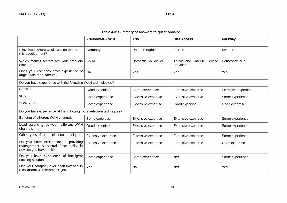
BATS (317533) D2.4
07/06/2013 44
Table 4-3: Summary of answers to questionnaire.
Fraunhofer-Fokus Xrio One Access Forsway
If involved, where would you undertake this development?
Germany United Kingdom France Sweden
Which market sectors are your products aimed at?
SoHo Domestic/SoHo/SME Telcos and Satellite Service providers
Domestic/SoHo
Does your company have experience of large scale manufacture?
No Yes Yes Yes
Do you have experience with the following WAN technologies?
Satellite Good expertise Some experience Extensive expertise Extensive expertise
xDSL Some experience Extensive expertise Extensive expertise Some experience
3G/4G/LTE Some experience Extensive expertise Good expertise Good expertise
Do you have experience of the following route selection techniques?
Bonding of different WAN channels Some expertise Extensive expertise Extensive expertise Some experience
Load balancing between different WAN channels
Good expertise Extensive expertise Extensive expertise Some experience
Other types of route selection techniques Extensive expertise Extensive expertise Extensive expertise Some experience
Do you have experience of providing management & control functionality in devices you have built?
Extensive expertise Extensive expertise Extensive expertise Good expertise
Do you have experience of intelligent caching solutions?
Some experience Some experience N/A Some experience
Has your company ever been involved in a collaborative research project?
Yes No N/A Yes

BATS (317533) D2.4
07/06/2013 45
Table 4-4: Down-selection weighted table.
All EU
Forsway 6.2 8.0 8.6 8.2 3.4 3.0 5.6 4.6 6.6 7.0 8.0 764 0
FH & Wiback 5.8 6.8 6.8 3.2 5.2 7.6 7.8 3.2 6.6 6.6 7.0 771 0
OneAccess/UDCast 8.2 7.2 8.2 6.2 7.8 7.8 7.8 3.2 7.0 7.6 7.4 877 0
Xrio 8.2 7.8 5.6 8.0 7.8 7.8 7.8 3.4 6.4 7.2 7.4 846 0
Weighting 6.0 6.0 6.0 2.5 8.8 8.0 10.3 3.8 15.5 18.3 15.0
Company DSL 3G/4G Satellite Consumer BondingLoad
balancing
Other route
selectionCache Integration Monitoring
Mean Weighted Score
Total Weights
100
Business
suitability

BATS (317533) D2.4
07/06/2013 46
4.3 Final selection of IUG Supplier By the time of writing this report, it has been decided that the lasts steps towards the final decision will involve the Steering Committee (SC). As a first step, the Statement of Work which will specify the activities from the DOW that we expect the selected company to perform needs to be agreed. Then, detailed negotiations with the three final candidates will be held in order to narrow down which is the best candidate. The final decision is planned to be announced in June 2013.
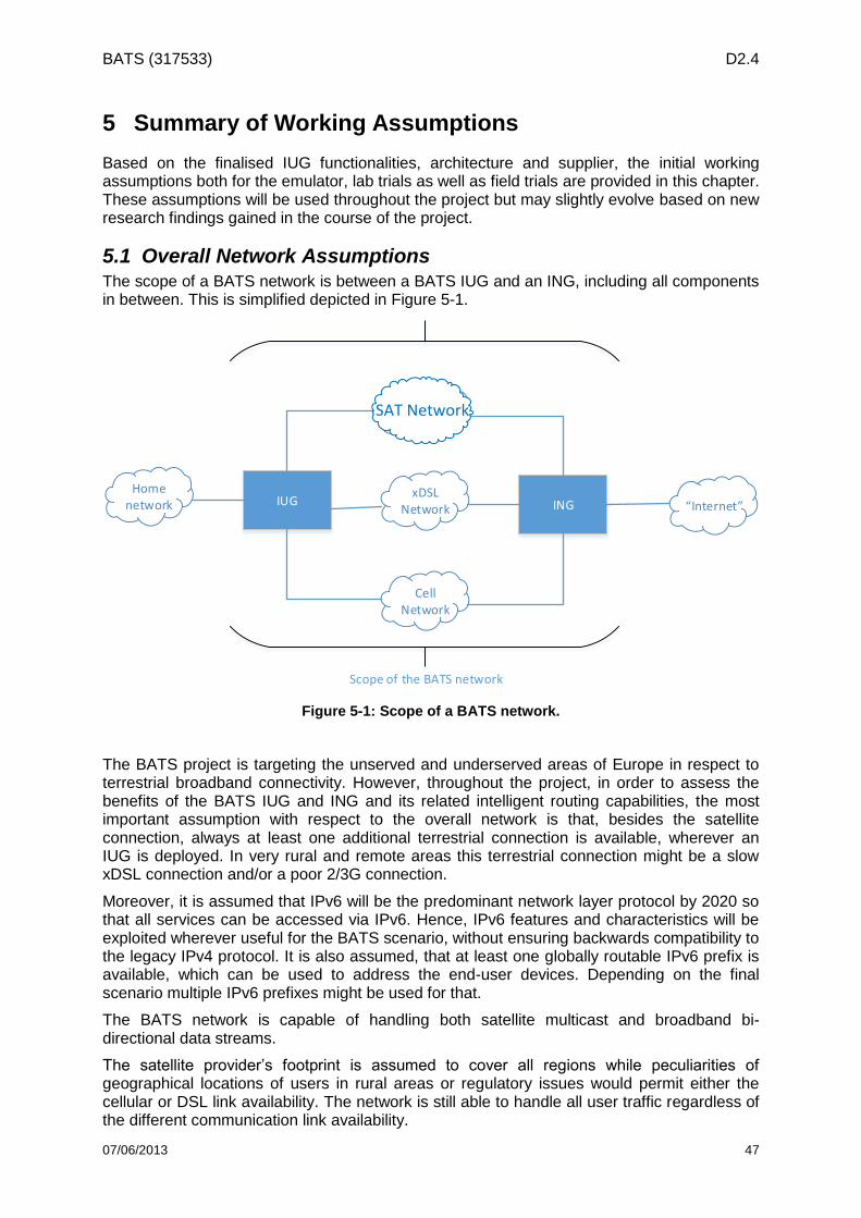
BATS (317533) D2.4
07/06/2013 47
5 Summary of Working Assumptions
Based on the finalised IUG functionalities, architecture and supplier, the initial working assumptions both for the emulator, lab trials as well as field trials are provided in this chapter. These assumptions will be used throughout the project but may slightly evolve based on new research findings gained in the course of the project.
5.1 Overall Network Assumptions The scope of a BATS network is between a BATS IUG and an ING, including all components in between. This is simplified depicted in Figure 5-1.
SAT Netowk
xDSL Network
CellNetwork
INGHome
network IUG “Internet”
Scope of the BATS network
Figure 5-1: Scope of a BATS network.
The BATS project is targeting the unserved and underserved areas of Europe in respect to terrestrial broadband connectivity. However, throughout the project, in order to assess the benefits of the BATS IUG and ING and its related intelligent routing capabilities, the most important assumption with respect to the overall network is that, besides the satellite connection, always at least one additional terrestrial connection is available, wherever an IUG is deployed. In very rural and remote areas this terrestrial connection might be a slow xDSL connection and/or a poor 2/3G connection.
Moreover, it is assumed that IPv6 will be the predominant network layer protocol by 2020 so that all services can be accessed via IPv6. Hence, IPv6 features and characteristics will be exploited wherever useful for the BATS scenario, without ensuring backwards compatibility to the legacy IPv4 protocol. It is also assumed, that at least one globally routable IPv6 prefix is available, which can be used to address the end-user devices. Depending on the final scenario multiple IPv6 prefixes might be used for that.
The BATS network is capable of handling both satellite multicast and broadband bi-directional data streams.
The satellite provider’s footprint is assumed to cover all regions while peculiarities of geographical locations of users in rural areas or regulatory issues would permit either the cellular or DSL link availability. The network is still able to handle all user traffic regardless of the different communication link availability.
SAT Network

BATS (317533) D2.4
07/06/2013 48
The security in the BATS network is guaranteed through the definition of security policies for the authentication of the users and devices, and the prevention of potential intrusions and misuses. Moreover, the user data are encrypted and decrypted through the IUG in order to provide a high level of security in the data transfer.
5.2 Assumptions for the Satellite Link The unicast satellite link requirements are defined in D4.1.1, primarily in chapters 3 and 4 which cover issues such the modulation and air interfaces. In summary, it will use DVB S2 with DVB RCS2 or their successors if appropriate. The forward link carriers will be 400Msps and the return link 20Msps.
The multicast satellite link requirements are also defined in D4.1.1. In summary, it will use DVB S2 (or successor) with ACM linked to the unicast link performance. This may need to have links to the multicast cache content distribution system to reduce flows when the multicast link requires operation at a slower data rate (higher FEC and/or lower modulation index) due to the average weather conditions.
The unicast carrier and the multicast carrier will be uplinked from the same gateway. The location of this gateway will be defined by the satellite architecture and site availability and may well not be in the same country as the user terminals. Additionally, at any given time, the carriers may be transmitted from the backup gateway to mitigate the impact of rain at their primary gateway location. It is likely that the satellite operator will have a number of POPs across the EU27+Turkey. The field trial will be carried on Hylas capacity. For example the gateway for Hylas 1 is in the UK and the user terminals in Spain. Avanti has a number of POPs across Europe.
The multicast data will be multiplexed on one of the large data carriers in each spot, therefore, by definition; this will be in the same frequency band and on the same polarisation as the unicast data carrier (see D4.1.1 Annex C solution 2b). The unicast data may not be on the same carrier however so a separate multicast receiver is required.
It may not be possible to test the multicast caching in the lab trials, though the QoE benefits can be simulated. The field trial tests may only implement a subset of the multicast caching benefits.
The modem and other user terminal requirements are given in chapter 7 of D4.1.1. In summary, a 74 cm or smaller antenna will be required with a highly reliable low cost satellite modem / receiver. One or both of the satellite modem and the multicast receiver can be integrated into the IUG.
5.3 Assumptions for the Digital Subscriber Line In the next paragraphs we introduce the xDSL assumptions to be used in the lab and field trials and in subsequent WPs in the project.
Depending of the BATS scenario, xDSL communication technology could be available at the users’ home. The xDSL service may be provided by a terrestrial operator, the BATS operator or a wholesale operator that resells the service. We assume that a DSL service is available for the field trials. The available xDSL technologies in these cases would be ADSL2+ or VDSL2 as these are the minimum xDSL technologies currently available for the field trials.
In the loosely and partially integrated IUG scenarios, the xDSL operator also provides the necessary DSL equipment to the end user. This equipment (modem or router) provides the necessary interfaces to the IUG to manage the communication at the level that is defined in each scenario. The CPE is connected to a corresponding DSLAM-IP that filters and separates the POTS (Plain old telephone service) voice traffic from the data traffic.

BATS (317533) D2.4
07/06/2013 49
In the case of ADSL2+, the transmission technology would be Ethernet over ATM communications protocols layers and the CPE needs to manage the ATMs Virtual Path and Virtual Channel (VP/VC) to ensure the routing over the ATM layer.
Figure 5-2 Protocol structure in ADSL2+ connections
In the case of the use of the VDSL2 technology between the CPE and the DSLAM, the Ethernet layer would be directly over the VDSL2 physical layer.
Figure 5-3 Protocol structure in VDSL2 connections
In both types of connections, there would be only one VLAN defined in the VDSL2 connection or one VP/VC for the ADSL2+ technologies.
The DSLAM-IPs in every switching station are directly connected to the IP backbone of the operator or through a Metro Ethernet network (CORE IP-MPLS).
In Table 5-1, there is an estimation of the available bandwidth with the different assumed xDSL technologies in function of the length of the copper pair, the general attenuation of the line and the specific attenuation in the frequencies of the xDSL technologies between the DSLAM and the end user home.

BATS (317533) D2.4
07/06/2013 50
Table 5-1 xDSL available BandWidth vs. Pair Length and attenuation
Max. Available download speed
Maximum Copper Pair Length
Maximum ADSL attenuation
xDSL Technology
20 Mb 1300 m 24 dB ADSL2+
15 Mb 2000 m 35 dB ADSL2+
10 Mb 3000 m 47 dB ADSL2+
6 Mb 4050 m 56 dB ADSL2+
3 Mb 5100 m 64 dB ADSL2+
2 Mb 5600 m 66 dB ADSL2+
1 Mb 6900 m 70 dB ADSL2+
50 Mb 600 m 17 dB VDSL2
30 Mb 900 m 22 dB VDSL2
20 Mb 1200 m 27 dB VDSL2
15 Mb 1400 m 30 dB VDSL2
10 Mb 1700 m 34 dB VDSL2
6 Mb 2400 m 44 dB VDSL2
From the point of view of the BATS project, we assume capacities of the xDSL service using the minimum download speeds that can be guaranteed in live networks which should be the basis for the simulation in lab trials. These data is depicted in Table 5-2 below.
Table 5-2 xDSL Minimum peak capacities
Technology Download Speed Upload Speed Latency Jitter
ADSL2+ 1 Mbps 128 Kbps 10 ms 0 ms
VDSL2 6 Mbps 256 Kbps 10 ms 0 ms
5.4 Assumptions for the Cellular Technology In order to assume capacity and performance characteristics of the terrestrial technology used, the following definitions will form the basis on which the assumptions for the cellular link will be made in WP3.
Technology Assumption: Assuming that LTE will prevail in a few years in the cellular domain but 2G/3G legacy networks will continue to survive in the EU, it is reasonable to assume an overall architecture in which LTE is the primary technology and 2G/3G technologies are used secondarily (less often). For high capacity -demanding services LTE may be assumed, for the others 2G and 3G. On the other hand, it should be noted that LTE availability in certain rural areas may not become a standard in the coming years and 2G and 3G may be the available options for these areas.
Backhaul & Backbone Assumption: The current trend in LTE backhauling is to use fast (gigabit) Ethernet interfaces between eNBs and a metro-ethernet-based switching office which connects to EPC elements (s-GWs, MMEs, p-GWs, HSS etc.) over a high capacity IP router. In this architecture we can assume 3G traffic is directed to the switching office by a cell site router which picks up 3G user data from eNodeBs over fast Ethernet interfaces. IP routers then deliver 3G traffic to the 3G
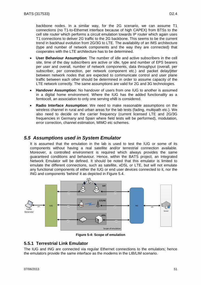
BATS (317533) D2.4
07/06/2013 51
backbone nodes. In a similar way, for the 2G scenario, we can assume T1 connections (no T1-to-Ethernet interface because of high CAPEX) from BTSs to the cell site router which performs a circuit emulation towards IP router which again uses T1 connections to deliver 2G traffic to the 2G backbone. This seems to be the current trend in backhaul evolution from 2G/3G to LTE. The availability of an IMS architecture (type and number of network components and the way they are connected) that cooperates with the LTE architecture has to be determined.
User Behaviour Assumption: The number of idle and active subscribers in the cell site, time of the day subscribers are active or idle, type and number of EPS bearers per user and overall, number of network components, data throughput (overall, per subscriber, per connection, per network component etc.) and packet delay/jitter between network nodes that are expected to communicate control and user plane traffic between each other should be determined in order to assume capacity of the LTE network correctly. The same assumptions are valid for 2G and 3G technologies.
Handover Assumption: No handover of users from one IUG to another is assumed in a digital home environment. Where the IUG has the added functionality as a femtocell, an association to only one serving eNB is considered.
Radio Interface Assumption: We need to make reasonable assumptions on the wireless channel in rural and urban areas for the lab tests (fading, multipath etc.). We also need to decide on the carrier frequency (current licensed LTE and 2G/3G frequencies in Germany and Spain where field tests will be performed), modulation, error correction, channel estimation, MIMO etc schemes.
5.5 Assumptions used in System Emulator It is assumed that the emulation in the lab is used to test the IUG or some of its components without having a real satellite and/or terrestrial connection available. Moreover, a controlled environment is required which always provides the same guaranteed conditions and behaviour. Hence, within the BATS project, an Integrated Network Emulator will be defined. It should be noted that this emulator is limited to emulate the different connections, such as satellite, xDSL or LTE, but will not emulate any functional components of either the IUG or end user devices connected to it, nor the ING and components 'behind' it as depicted in Figure 5.4.
Scope of emulation
NIC
3N
IC2
NIC
1
2/3/4G
SAT
xDSL
IUG
TrafficGenerator Server
ING
eth
eth
eth
eth
eth
eth
eth eth
Figure 5-4: Scope of emulation
5.5.1 Terrestrial Link Emulator
The IUG and ING are connected via regular Ethernet connections to the emulators; hence the emulators provide the same interface as the modems in the LIB/LIM scenario.

BATS (317533) D2.4
07/06/2013 52
The Network Emulator (NetEmu) is an extension to the SENF7 framework using the Packet Processing Infrastructure (PPI) and allows for emulating network devices. The concept behind the PPI is known as the pipes and filters design pattern where each processing step is encapsulated in a filter component (called module in the PPI). The modules are completely independent and connected to each other using dynamically pluggable connections. Thereby each module exposes a very simple interface. It receives packets on the input connection, processes the packet, and publishes the results to the output connection. This architecture supports loose coupling.
NetEmu brings an abstract layer for the use of network devices with the extension to emulate such devices. These layers provide different kind of abstraction levels, e.g. an 802.11 device could be represented as a generic Network Interface, which provides basic functionalities like read/write frames. It could also be represented by a rather detailed wireless interface, which allows e.g. to set frequency and transmit power. Figure 5-5 depicts the inheritance structure for the emulated WLAN Interface. As can be seen the NetEmu utilizes multiple inheritance to plug together different functionalities for a network interface. By separating receiver and transmitter behavior into different classes unidirectional technologies like DVB can be described as well. The modularized PPI structure also allows for emulating other technologies such as xDSL or LTE by combining different PPI modules such as a packet delayer, a packet dropper, a bit error injector or a bandwidth limiter.
Figure 5-5: Class diagram for the Emulated WLAN Interface
The main goal of the NetEmu is to provide a real-time emulation framework in order to evaluate quickly, easily and, most importantly, on a larger scale, higher layer network protocols. NetEmu introduces emulated interfaces such as Wireless Local Area Network (WLAN), Ethernet, DVB-T, DSL or LTE. To emulate links between the emulated nodes multicast groups are used. The assignment of a certain multicast group is based on physical parameters of the emulated technology and all interfaces within the same technology-specific broadcast domain, i.e. wireless interfaces which are tuned on the same frequency, channel bandwidth pair, can exchange packets while being in each other’s emulated communication range. One advantage of this approach is that this also works between multiple machines across an Ethernet switch which allows for emulating very large scenarios.
An example of a packet flow is depicted in Figure 5.6 for a packet sent over an emulated wireless link. The packet transmitted over an emulated physical link is prepended with a list of meta information, such as transmission power used to send this frame, sequence number,
7 http://senf.berlios.de

BATS (317533) D2.4
07/06/2013 53
and transmit timestamp in the emulated wireless transmit filter and the emulated transmit filter, respectively. Upon reception on the emulated receiver the meta information is examined by the emulation layer. Based on transmission power and GPS coordinates of each emulated node, given in a configuration file, the attenuation introduced by the free space path loss across the link from sender to receiver and the resulting Received Signal Strength Indication (RSSI) value is calculated. If the RSSI is above the receiver’s threshold, the frame is passed on, otherwise it is dropped. To more closely emulate real world conditions, packet loss and delay (constant and burst) as well as bit error rate can be added on each link in the Packet Delayer and the Packet Dropper, respectively. The passive socket sink and the active socket source are responsible for sending and receiving the packets to the interface.
Figure 5-6: NetEmu modules for the Emulated Wireless Interface
It should be noted, however, that NetEmu does not emulate technology specific MAC and PHY layer characteristics, such as channel access, TDMA synchronisation or SC-FDMA channel separation. It has rather been designed to support scalability evaluations of higher layer protocols and mechanisms. In the BATS context, NetEmu can be used to emulate DSL, LTE and SAT links by providing corresponding link characteristics which can be described via typical bandwidth, latency, jitter and loss probability/distribution. Figure 5-7 shows a simplified model for the emulated LTE link. Depending on the number of users/IUGs in a cell, associated to one eNB, NetEmu is configured to depict the characteristics of these N links. For bidirectional technologies, the aforementioned parameters can be given for up- and down-link individually. Furthermore, due to its architecture NetEmu allows for using the same source code on real-hardware nodes as well as in the emulation environment, which is essential for a longer term R&D project since developing and, particularly, maintaining two code bases would create a large overhead.

BATS (317533) D2.4
07/06/2013 54
LTE Cell Model
latency losslatency channel lossBandwidth
limiter
latencychannel lossBandwidth
limiter
Eth
Eth
1
latency losslatency channel lossBandwidth
limiter
latencychannel lossBandwidth
limiter
Eth
N
. . .
Figure 5-7: Simplified modules for emulating the LTE link.
5.5.2 Satellite Link Emulator
The emulation of the satellite access network is based on the OpenSAND emulation testbed [15], developed by Thales Alenia Space and the CNES and release under open source license (GPL and LGPLv3). Owing to its modular design and implementation, the OpenSAND satellite emulation platform is able to emulate a complete star DVB-RCS (Digital Video Broadcasting – Return Channel via Satellite) - DVB-S2 (Digital Video Broadcasting – Second generation) system in a realistic and flexible way (Figure 5-8).
Figure 5-8: Emulated Satcom System

BATS (317533) D2.4
07/06/2013 55
OpenSAND offers either IPv4/IPv6 or Ethernet (untagged or tagged) network interfaces to interconnect clients, servers or proxies. It also emulates the DVB-RCS/S2 access layer, including the layer 2 scheduling and the radio resource management. Both ATM and MPEG-2 TS profiles of DVB-RCS are supported, each with different encapsulation schemes (AAL5; ULE). On the forward link GSE or MPEG2-TS can be used. In addition, header compression (RHOC) is supported. The adaptive physical layer is emulated in real time thanks to pre-calculated modulation and coding schemes on both forward and return links. At the network side, IPv6 mobility and dynamic multicast routing thanks to the corresponding proxies/routers. The general OpenSAND architecture and bloc definition is shown in Figure 5-9:
Figure 5-9: OpenSAND architecture
Each network element involved in the satellite network is emulated in OpenSAND on a dedicated node. For validation purposes, virtualization can be used. The satellite core network is emulated thanks to the Satellite Emulator (SE) as link emulator and Network Control Center (GW) for bandwidth management (DAMA) and several Satellite Terminals (STs) interconnected through a Gigabit Ethernet switch.
The emulation testbed takes advantage of Linux systems (Ubuntu Server LTS) which natively supports IPv6 and a wide panel of IPv4/v6 applications, as well as advanced network features (e.g. IP QoS, routing, mobility…). Moreover, the platform also benefits from a real-time patch if installed (low latency kernel) to reduce the thread scheduling jitter.
Finally, OpenSAND offers a controller able to install, deploy, configure, control and operate the emulation testbed. It is based on a framework (see Figure 5-10) in charge of collecting errors, events and probes (with pre-processing features) from emulation components (through the local OpenSAND Daemon) to the corresponding centralized collectors. These are in charge of data post processing and data storage into files and are connected to the OpenSAND GUI manager for display either in real time or offline components’ probes.

BATS (317533) D2.4
07/06/2013 56
Figure 5-10: environment plane architecture
5.5.3 Assumptions on subjective experiments for proof of BATS concept (lab trials)
This section describes the subjective experiments that will be carried out within BATS project to assess the Quality of Experience of the overall system. However, in this deliverable we focus only on the subjective assessments that will be carried out within the scope of the lab trials in WP6. It should be noted that there will be further assessments on different demonstration scenarios within the scope of the field trials in WP7. Four types of broadband applications are considered for assessment of the Quality of Experience of users.
Web browsing/Email
Video Streaming
Gaming
Video Calling/Video Conferencing Three types of broadband access methods are emulated.
Terrestrial only (LTE/xDSL)
Satellite only
BATS scenario Two types of subjective experiments will be conducted. Demonstration scenario 1 Objective: The objective of this experiment is to assess the improvement of QoE obtained by intelligent aggregation of terrestrial and satellite networks.

BATS (317533) D2.4
07/06/2013 57
A single user will use the individual broadband applications over different broadband access methods. Thus, there will be only one type of application that is accessed through the broadband network at a given time. Stimuli to be used in this experiment: The subjects are presented with the following stimuli to assess.
2 web browsing sessions lasting 2 minutes: The subjects will access non video content such as email, Wikipedia or social networking sites such as Twitter or Facebook
6 video streams encoded with H.264 video coding standard: This set will include 3 high definition videos and 3 standard definition videos. Each video stream will be 20s long.
2 video streams that are 5 minutes long, which will be streamed from the internet and streamed from a local cache.
2 gaming sessions: Both games will be accessible online, one will be a single player game and the other a multiplayer game.
2 video calls: lasting 1 minute The total duration of presentation of the above stimuli, over one particular emulated access network, is approximately 30 minutes. Thus, the entire subjective experiment will last for a duration of 1 hour and 30 minutes for each subject. The stimuli will be presented in three assessment sessions that last up to 30 minutes. Procedure: The user will rate the quality of experience of using those applications. The user will be asked to rate the overall quality of experience on a scale of 0-100, with adjectival guidance as shown on figure 1.
Figure 5-11: Rating scale to be adopted in subjective experiments
Subject recruitment: It is assumed that all the subjects that participate in this study are non-experts in terms of quality assessment and they have normal or corrected-to-normal visual and auditory capabilities.

BATS (317533) D2.4
07/06/2013 58
It is expected to recruit at least twenty four subjects for this experiment. Similar numbers of subjects will be recruited in four age groups (<20, 20-34, 34-55, 55>). Furthermore, the selected subjects should have a representation from urban, semi-rural and rural areas. Statistical processing of subjective results: The subjective results will be statistically analysed with techniques such as ANOVA (Analysis of Variance) and cluster analysis to uncover any patters associated with subjective scoring. Furthermore, statistical analysis will provide indications of the improvements of QoE brought about by the BATS system. Demonstration scenario 2 Objective: The objective of this experiment is to assess the effectiveness of differential treatment of traffic in the IUG. In this experiment, a single/multiple user(s) will use the combination of two or more broadband applications over different broadband access methods. In this case, there will be more than one type of application that is accessed through the broadband network, at a given time, and illustrate effectiveness of differential treatment of different traffic types. This experiment will also consider a single user accessing different applications through a single device and through multiple devices. Stimuli to be used in this experiment: The stimuli used in this experiment are the same as those in experiment 1. However, the pattern of presentation is different, since in this experiment a user will be accessing more than one type of broadband application. The following combinations of applications will be assessed. It should be noted that the scenarios identified in Table 5-3 Scenarios showing combination of applications with two users are not exhaustive and may change in the future. Table 5-3 Scenarios showing combination of applications with two users
Scenario User 1 User 2
1 Web browsing, Video Streaming and Video Calling
None
2 Web browsing, Video Calling Video Streaming
3 Video Calling, Gaming Web browsing, Gaming
4 Video Streaming Gaming, Web browsing
Procedure: The user(s) will rate the quality of experience of individual applications as well as the overall experience of the broadband connection. Similar to the first experiment, the users will be asked to rate their experience on a scale of 0-100, with adjectival guidance as shown on Figure 5-11. The subject recruitment and statistical processing of the subjective results will be similar to the demonstration scenario 1.

BATS (317533) D2.4
07/06/2013 59
6 Conclusion
This deliverable has considered the overall BATS architecture and for the first time the role of an ING within the network side. The original idea was to have just an IUG at the customer premises but this does not allow the traffic routing/splitting advantages to be available on the downlink and constrains the communication from BATS to BATS users and from BATS to non-BATS connection advantages. Thus herein we have considered an ING, which is the counter part of the IUG on the network side of the architecture.
Three options were considered;
No ING
Centralised ING
Decentralised ING
The No ING option is feasible but only provides the routing and traffic splitting advantages on the uplink and not on the down link and for a non-BATS initiated call the IUG has only limited means to route the traffic.
The centralised option provides one single connection point to all BATS and non-BATS users. It simplifies the routing and hides the complexity from all of the users. It also provides the facility to route the traffic on the down link which was not available in the “no ING” case. Three options for the location of the ING were considered;
Satellite operator hub with terrestrial networks in a different country
Terrestrial operator POP with the satellite operator hub being in a different country.
At the POP in the same country as the satellite operator hub
The difference between these options relates to the terrestrial connections affecting the QoS and needs to be evaluated further in WP3.
The decentralised option has multiple ING’s operating in a distributed manner located in each operator network in order to share information about available links and to forward traffic to another network if this is advantageous. This allows both up and down link advantages but there are some restrictions on per flow and per packet routing doesn’t seem possible.
Based on the evaluation provided in section 2.1 the centralised option was chosen as the baseline to pass onto WP3. The decision as to where the ING should be placed is left to further study as this will be impacted by both the technical aspects affecting QoS (WP3) and the business case (WP5).
In section 2.2 the BATS IUG/ING functional components are outlined based on the architecture presented in D 2.3. These are defined under the management plane, control plane and intelligent routing plane. The ING is extrapolated from the IUG that has already been defined. This is followed in section 2.3 by a definition of the traffic flows between the three planes. In section 2.4 there is a definition of the interfaces between the functional components and in section 2.5 a detailed specification of the protocols on these interfaces. Thus sections 2.2 to 2.5 provide the detailed functional description of the IUG/ING on which WP3 will consider its implementation.
Section 3 of the deliverable addresses the IUG integration with other components of the architecture—the modems (xDSL, LTE/3G and satellite), the operator network and the user home network.
The integration with the modems and the incorporation of the separate multicast transmissions is addressed in section 3.1. The multicast receiver can ideally be integrated with the broadband modem if a solution similar to that of the HbbTV is used. This means that

BATS (317533) D2.4
07/06/2013 60
there is no need for an additional receive chain. The xDSL and LTE/3G modem interfaces are well defined leading to an easy integration into the IUG itself. However the satellite modem’s currently vary between manufacturers and it would be difficult to conceive a full integration (hence a PIB realisation). However if the new DVB-RCS2 standardisation of an open IP infrastructure is widely adopted by 2020 then a full integration should be possible (the FIB realisation). In the PIB realisation, control and management plane interfaces need to be further studied in WP3.
As far as operator integration is concerned it was decided in D2.3 to adopt either a single BATS operator or an integrated VNO. The major issues described in the deliverable surround the different and variable SLA’s with the three operators as well as the OAM over these independent operator networks. Here virtualisation is suggested as a solution but the different country regulations could pose a problem in operating this solution internationally. Billing is another issue which will be studied further in WP5. Many of the operator issues have already been described in section 2.1 especially relating to the terrestrial connections the IUG and ING’s. These matters will be further evaluated in WP3 and WP5.
Section 3.3 investigates the user end integration of the IUG and its routing. Initially 5 methods for traffic classification were outlined from work in the literature and these were mapped onto the IUG architecture and the QoE determination. It is concluded that a combination of the methods would be needed to cover all of the application sets. However it is recommended that two methods which relate to the ports used by the applications and a payload method which classifies traffic using the headers and the payload packets themselves are used in the prototype IUG. The second part of this section addresses the connection of the home user equipment to the IUG. The recommendation here is to use a WiFi router rather than individual wired connections to the devices and to connect this via Ethernet to the IUG. Various levels of integration of the latter can be investigated in the implementation.
Section 3.4 addresses the research challenges to the satellite network design and points out major areas to be considered further that deal with;
Multicast and multicast ACM at the terminal and gateway.
Dynamic switching between multicast and unicast.
Connections between the IUG and ING and the location of the latter.
Minimisation of energy in the CPE and gateway connections.
Synchronisation between the three paths affecting the air interface.
Remote maintenance and reliability issues of the CPE.
In each of the above cases the follow up WP’s that deal with the issues are documented.
Section 4 continues the work started in D 2.3 on the selection of the IUG supplier and details the process that was followed to reduce 7 companies down to 3. The latter have now been invited to bid to a specification for the IUG and a final choice will be made in June.
Section 5 contains a summary of the working assumptions for the network architecture, satellite-xDSL-Cellular links and these will be the basis of the follow on work for the implementation of the IUG and for the network emulators in WP3 and WP6 respectively. Finally a first review of the subjective experiments that could be carried out in the Lab trials is presented and will be used in WP 3 as early requirements for the IUG prototype and in WP 6 for more detailed design of the trials.

BATS (317533) D2.4
07/06/2013 61
7 References
[1] http://en.wikipedia.org/wiki/Home_network
[2] http://www.thinkbroadband.com/guide/home-networking.html
[3] ACG Research “Scaling the Control Plane With the Ericsson Smart Services Router”
2012.
[4] Home Gateway Technical Requirements: Residential Profile, Version 1.0, 2008
[5] TR-124: “Functional Requirements for Broadband Residential Gateway Devices” December 2006
[6] TR-062 - Auto-Configuration for the Connection Between the DSL Broadband Network Termination (B-NT) and the Network using ATM.
[7] TR-069 Amendment 3, CPE WAN Management Protocol, Broadband Forum, 2010
[8] TR-196: “Femto Access Point Service Data Model”, Issue: 1, April 2009
[9] Callado, A.; Kamienski, C.; Szabo, G.; Gero, B.; Kelner, J.; Fernandes, S.; Sadok, D., "A Survey on Internet Traffic Identification," Communications Surveys & Tutorials, IEEE , vol.11, no.3, pp.37,52, 3rd Quarter 2009
[10] Dainotti, A.; Pescape, A.; Claffy, K.C., "Issues and future directions in traffic classification," Network, IEEE , vol.26, no.1, pp.35,40, January-February 2012
[11] WiBACK website, http://net4dc.fokus.fraunhofer.de/en/projects/wiback.html.
[12] Xrio website, http://www.xrio.com
[13] OneAccess website, http://www.oneaccess-net.com
[14] Forsway website, http://www.forsway.com
[15] OpenSAND emulation testbed, http://www.opensand.org

BATS (317533) D2.4
07/06/2013 62
Intentionally blank

BATS (317533) D2.4
07/06/2013 63
Annex A - IUG supplier selection process (Additional information)
Information captured during process
Fraunhofer-Fokus
Fraunhofer-Fokus claims that one of their existing technological solutions called Wireless Backhaul Technology (WiBACK) [11] can be adapted to become the BATS IUG for the lab/field trials. WiBACK targets carrier grade service provisioning in very large wireless networks. Key features of WiBACK include QoS-provisioning, auto-configuration, self-management and self-healing. The technical approach includes multi-hop heterogeneous radio technologies, MPLS and QoS support, IPv4 and IPv6 interworking, network auto-configuration, and an IEEE 8002.21-inspired media-independent messaging mechanism. Access is provided by any type of interface, including GSM, wireless LAN, and Ethernet. Fraunhofer-Fokus has explained briefly which is the additional development that will need to be done to the WiBACK solution to make it become the BATS IUG and additional information is provided below.
Fraunhofer-Fokus was asked to answer a questionnaire to assess their suitability as IUG suppliers. Their answers are provided in Table 7-1.
Table 7-1: IUG Questionnaire - Fraunhofer.
1 If involved, where would you undertake this development? Germany
2 Which market sectors are your products aimed at? SOHO
3 Does your company have experience of large scale manufacture?
No
Can you provide evidence of this?
4 Do you have experience with the following WAN technologies?
a) Satellite Good expertise
b) DSL Some experience
c) 3G/4G/LTE Some experience
Can you provide evidence of this?
SAT: Previous work on DVB Data Piping, implementation of DVB-S/T Encapsulator and TCP PEP, participation in Satellite EU Projects.
DSL/LTE: Initial/Simple Integration into WiBACK via tunnelling incl. capacity estimation, monitoring, etc. Currently studying abstraction models for DSL and in particular (rather volatile) LTE connectivity.
5 Do you have experience of the following route selection techniques?
d) Bonding of different WAN channels Some expertise
e) Load balancing between different WAN channels Good expertise
f) Other types of route selection techniques Extensive expertise

BATS (317533) D2.4
07/06/2013 64
Can you provide evidence of this?
d+e) In the context of WiBACK, we consider bonding and especially load balancing across multiple parallel links to increase the overall capacity. Also, out DVB-T encapsulator may utilize DVB-T and DSL in downstream direction, while upstream is DSL only.
Other: Constraint-based routing via MPLS (Traffic Engineering)
6 g) Do you have experience of providing management &
control functionality in devices you have built? Extensive expertise
Can you provide evidence of this?
WiBACK provides an extensive monitoring subsystem regarding PHY, MAC and LSP statistics. This information is used by the WiBACK management components for e.g. topology optimizations.
7 h) Do you have experience of intelligent caching solutions?
Some experience
Can you provide evidence of this?
8 Has your company ever been involved in a collaborative research project?
Yes
Can you provide evidence of this?
Numerous EU (F6 + FP7) or German Research Projects such as Daidalos, CARMEN, SatNEx, BASE2
10 Would you like to know more about this project and study possibilities for your collaboration? Select one answer
Yes
Additional relevant information was received during conversations held via e-mail:
“Hardware-wise we would need to integrate a different board than we are currently using, which has four Ethernet connector and a more computational power. Furthermore, we'd need to select a different casing since the requirements are different in BATS, i.e. we don't need an outdoor device but more Ethernet connectors, etc. Here the effort is difficult to specify as there are still so many uncertainties re the feature the IUG should provide in the end. If the IUG will be a routing device, placed somewhere in a house, which might have a hard disk for caching some content and a three modems connected via Ethernet or USB, I'd say we can make this modification with approx. 3 PMs.”
“Software-wise basically three main modules would be required: a) a traffic classification engine, b) a load distributor and c) link capability detection. At least for c) and probably also for b) the effort highly depends on the integration scenario we're planing to realize in the field trials. If we are targeting a similar scenario as Viprinet would have implemented (VISP, VPN-tunneling), the effort would lower than e.g. the multiple, completely independent operator scenario, since this scenario would suit more with the existing WiBACK architecture. Particularly, since in this scenario there will be an IUG counterpart on the operator site which will act as a single point of concat to the outside world, leading to the fact and we don't have to deal with the IP multihoming issues. A very rough estimation would be that we require between 9-15PMs for the modifications depending on the exact requirements.”

BATS (317533) D2.4
07/06/2013 65
Xrio
Xrio [12] is a small UK-based company specialised in the design and manufacturing of broadband routers for domestic/SME markets which are capable of bonding the broadband traffic over different xDSL and 3G links. In their own words “whatever the setup, Xrio products can improve the speed, quality and reliability” of Internet or WAN connectivity”. Xrio is primarily a software company. To ensure optimised performance of the software, Xrio assists with the design, approval and sourcing of hardware solutions for its customers. They can supply their own hardware as Xrio-branded or white-labelled. Xrio’s Operating Software (XriOS) incorporates a wide range of features to which have evolved over 10 years to provide their core competency of Bonding, Load Balancing and Failover solutions.
Their products include, among others, the following set of features:
- Internet and WAN failover
- Link Bonding
- WAN load balancing
- VPN bonding
- 3G/4G connectivity
- WAN optimisation
- Forward Error correction
- Virtualisation
- Live performance monitoring
- Centralised Management
- System monitoring
- Auto deployment and provisioning
- Traffic shaping
- Dynamic routing
- Firewalling
- Access gateway (NAT/DHCP)
- Sito to site VPN (IPSEC)
- Reporting and diagnostics
- Policy based routing
- High availability
- Rest API (HTTP, XML, JSON)
- Ipv6 ready
- Network Auto response System.
“Wrt the integration in an operator network we definitely need to better understand the operator's requirements. First and foremost what interfaces are used? In the VISP, VPN-tunneling scenario we can easily provide L2-briding between the IUGs and their counterpart allowing for VLAN tagging and/or MPLS interfacing. The answer to questions about the monitoring capabilities is similar. The monitoring engine of WiBACK is already very sophisticated and we're able to process and provide various information. However, depending on the scenario the adoption required to gain the necessary information from the underlying networks as well as implementing the interfaces required by the operators might be considerable, e.g. we're currently not providing a SMNP interface.”

BATS (317533) D2.4
07/06/2013 66
The “anatomy” of their products is illustrated in Figure 7-1.
They have strong expertise in smart routing and load balancing techniques. They claim the BATS IUG is in line with their vision for their future products and are willing to collaborate with BATS by developing a prototype adapted to the interest of the project.
Xrio was asked to answer a questionnaire to assess their suitability as IUG suppliers. Their answers are provided below.
Figure 7-1: Xrio's anatomy.

BATS (317533) D2.4
07/06/2013 67
Table 7-2: IUG Questionnaire - Xrio.
1 If involved, where would you undertake this development? United Kingdom
2 Which market sectors are your products aimed at? Domestic/SoHo/SME
3 Does your company have experience of large scale manufacture?
Yes
Can you provide evidence of this?
Since being founded over 10 years ago, we have worked with several sources in Taiwan and China to build and manufacture hardware solutions to fit the requirements of our software platform.
4 Do you have experience with the following WAN technologies?
g) Satellite Some expertise
h) DSL Extensive expertise
i) 3G/4G/LTE Extensive expertise
Can you provide evidence of this?
Our devices have built in ADSL/2+ (up to 4 ports) and 3G/4G connectivity directly into the hardware, no need for external modems. We have in excess of 3000 of these devices in the field. We can provide customer references if required.
5 Do you have experience of the following route selection techniques?
j) Bonding of different WAN channels Extensive expertise
k) Load balancing between different WAN channels Extensive expertise
l) Other types of route selection techniques Extensive expertise
Can you provide evidence of this?
Bonding, Load Balancing and Advanced Policy Based Routing is our core compentecy and have been providing solutions to customers with these functionalities for 10 years.
6 g) Do you have experience of providing management &
control functionality in devices you have built? Extensive Expertise
Can you provide evidence of this?
We have various API;s for configuration, management and monitoring including a REST API supporting HTTP, XML, JSON etc. as well as other common protocols such as SMTP and Netflow.
7 i) Do you have experience of intelligent caching solutions?
Some expertise
Can you provide evidence of this?
We have basic web caching functionality in the product, and our team have knowledge of various technologies. We would be willing to work with you to add such functionalities to our modular system.
8 Has your company ever been involved in a collaborative research project?
No
Can you provide evidence of this?
Not of this kind, mostly have been commercial collaborations with various leading Telco’s around Europe.
BATS (317533) D2.4
07/06/2013 68
10 Would you like to know more about this project and study possibilities for your collaboration?
Yes
Additional relevant information was received during conversations held via e-mail:
OneAccess
OneAccess [13] positions itself as “the agile, purpose-built solution for Telcos who wish to deliver business customer value and achieve real competitive advantage”. With a broad portfolio of more than 30 products from routers, Ethernet access devices to software for managed services, OneAccess is a leading global manufacturer of telecommunication devices. Deployed in more than 60 countries, OneAccess works closely with more than 120 Telecom Operators located in Europe, Asia, Middle-East and Latin America.
OneAccess products are widely deployed by Telcos and designed to (i) support the delivery of innovative services and (ii) enable the migration from legacy technologies to IP. Our company is recognized within the industry as being customer centric with an ability to meet Telcos' needs through a long-term partnership approach. OneAccess provides its customers with the necessary technical support enabling them to successfully develop and deliver service innovation.
OneAccess ships today a wide range of routers with the following WAN technologies:
ADSL
VDSL
SHDSL.bis (ATM, IMA and EFM flavors)
Fiber
3G (LTE is in roadmap for end of 2013)
Their series of product ONE15xx deliver the following features:
Extreme performance in a compact, low power-consumption hardware
Dual-core architecture with a CPU core dedicated to the addition of value-added services. The AppInside Software Development Kit (SDK) makes this CPU core open for authorized 3rd party developers who wish to build their own applications within ONE15xx platform.
WAN optimization (application visibility, control and optimization) which aims at improving user experience, especially under challenging network conditions such as high latencies, losses and WAN bandwidth bottlenecks.
o The technology comes from UDcast acquisition, which was a leader in IP optimization over satellite. The technology integration in OneAccess routers benefits from 10+ year continuous development of acceleration technologies over satellite.
Link management capabilities are included as baseline router features. They include:
o Various load sharing strategies (per session, packet, source or destination IP).
o Policy-based routing decision to overflow less latency-sensitive traffic on satellite
“There are some features that may be of use that are currently in their final stages of development (BETA expected in around 4 weeks). Specifically our Network Auto Response System (NARS) and improvements to our Live Performance Monitoring system but we can certainly show you a Proof of Concept on these parts.”

BATS (317533) D2.4
07/06/2013 69
o Various decision triggers to probe link availability (routing protocols, traffic probe) and switch traffic to backup links
User experience can be analyzed by means of embedded application performance metrics delivered by the NetAPM software option in OneAccess routers. NetAPM reports raw per-flow metrics to the OneAPM server, which aggregates information and provides advanced reporting features. The following metrics can be analyzed on a per-link basis and a per application basis:
o Server response times (basically time between HTTP GET and 200 OK) o Network round trip times o TCP efficiency (i.e. a measurement of TCP retransmissions) o VoIP quality o Bandwidth o … and many more drill-down options
OneAccess points out the following features of their products as potential contributions to the BATS IUG:
AppInside SDK:
This SDK could let project partners prototype and develop value-added software within OneAcces routers. They could focus on “standard” router features, while project partners can think of innovative features to measure and improve QoE as well as maximizing link utilization.
Measurement of User Experience:
OneAccess APM technology can be involved to measure network metrics impacting user experience.
Smart Path Control:
OneAccess considers the development of Smart Path Control in its product, which can deliver a suitable component for the BATS project.
The goal behind Smart Path Control is to simultaneously use multiple links and benefit from the best characteristics of each links.
OneAccess experience with satellite shows that web browsing on high-speed satellite is highly correlated to the number of RTT. When RTT is low, bandwidth becomes the bottleneck. Smart Path control aims at taking best of both worlds. Small HTTP objects should be transferred over DSL, while large objects should be transferred over satellite. The decision must be dynamic and carried out in the course of the TCP sessions.
Existing link bonding technologies work at the packet level and re-assemble an IP stream with packet ordering preservation. This technology does not apply differentiated acceleration on a per link basis and has difficulties to adapt to link with varying RTT and bandwidth. So, while this solution could appear interesting, it remains challenging to make it solve all use cases with an optimum result.
OneAccess suggests that a multi-path TCP based solution (or equivalent) will deliver a suitable solution. Implementing this technology in both client and servers is challenging:
It requires to update every servers one-by-one
It must be implemented on PC client. Its only implementation is today on Linux. Its configuration is tricky and cumbersome.
Too many conditions are thus required such that this technology can be successful.

BATS (317533) D2.4
07/06/2013 70
OneAccess believes that the right solution is to improve its NetBooster WAN optimization software with multi-path TCP capability. NetBooster intercepts TCP session transparently and would fork a single session into multiple sub-sessions. A concentrator terminates the multi-path TCP sessions and proxies the TCP session towards the server.
Note that the solution focuses mainly on TCP. UDP is usually 1-3% of total traffic with some exceptions. For UDP, the proposed solution is to use existing OneAccess router features:
o Delay sensitive traffic such as DNS or VoIP will be forwarded only to the lowest latency link, with backup on other links
o For other traffic, strategy needs to be chosen. For instance, UDP load sharing could be done on a per-destination IP destination basis.
OneAccess claims that they can bring the following assets to the BATS Project:
Advanced satellite knowledge
Open router platform for 3rd party development
Experience with management of multiple WAN links
Tools to collect performance metrics impacting user experience
Renown router player
Support of multiple WAN technologies in its product portfolio
WAN optimization technology, which can evolve towards multiple link scenarios.
One Access was asked to answer a questionnaire to assess their suitability as IUG suppliers. Their answers are provided in Table 7-3.
Table 7-3: IUG Questionnaire - One Access.
1 If involved, where would you undertake this development? France
2 Which market sectors are your products aimed at? We sell to Telcos or Satellite Service Providers
3 Does your company have experience of large scale manufacture?
Yes
Can you provide evidence of this?
OneAccess has shipped 150.000 routers worldwide in 2012.
4 Do you have experience with the following WAN technologies?
m) Satellite Extensive expertise
n) DSL Extensive expertise
o) 3G/4G/LTE Good expertise
Can you provide evidence of this?
- Satellite: Our UDgateway V5.4 implements enhanced acceleration and compression technologies. Customers like BT and NSSLGlobal in the UK have deployed our UDgateways on a large scale.
- DSL: The prime business of OneAccess is to market Multi Services Access Routers to Telcos, allowing them to provide managed Services to their en Customers. Deutsche Telekom and France Telecom belong to our maincustomers.
- 3G/4G/LTE: Whenever IP data transmission is concerned we have the expertise. We are
BATS (317533) D2.4
07/06/2013 71
participating to an experimental LTE platform in Sophia Antipolis together with Orange and ST-Ericsson. OneAccess markets 3G products in its portfolio and is working on its ONE1540 platform to add a 4G option.
5 Do you have experience of the following route selection techniques?
p) Bonding of different WAN channels Extensive expertise
q) Load balancing between different WAN channels Extensive expertise
r) Other types of route selection techniques Extensive expertise (automatic back-up, least cost routing)
Can you provide evidence of this?
- Bonding: we provide today L1/L2 bonding at EFM, IMA or MLPPP level.
- Load Balancing: Partnership with Thuraya to provide Optimized link bonding that combines link management with acceleration and compression technology to bond streams from multiple Thuraya IP terminals. Our Link Management feature on our UDgateway allows load balance the traffic between up to 3 links.
- Least Cost routing: OneAccess has implemented a solution with 21Net in high speed train allowing to switch automatically the Internet traffic from Satellite (countryside) to 3G (tunnels) to WiFi (Railway station)
6 g) Do you have experience of providing management &
control functionality in devices you have built? Extensive expertise
Can you provide evidence of this?
Because our products are used in telco managed services, extensive MIB and troubleshooting tools are provided. Our equipment can store and forward SNMP traps and Netflow tickets allowing to remotely manage, control and troubleshoot them.
7 j) Do you have experience of intelligent caching solutions?
N/A
Can you provide evidence of this?
N/A
8 Has your company ever been involved in a collaborative research project?
N/A
Can you provide evidence of this?
10 Would you like to know more about this project and study possibilities for your collaboration?
Yes
Additional relevant information was received during conversations held via e-mail:
In your opinion, and based on products you have knowledge of, how long would you take to develop a breadboard for such a development?
“If we were to integrate satellite technology, a daughter card would need to be developed by the satellite system supplier. For other interfaces, OneAccess has clearly to know-how. Our routers provide some extension interfaces where a daughter card can be plugged in. A hardware shrink or a new hardware combining already supported interfaces typically takes 6 months for hardware design (software not included).

BATS (317533) D2.4
07/06/2013 72
Forsway
Forsway [14] is a small company from Sweden which has been responsive and has claimed to be flexible and willing to reconfigure their solutions to more accurately meet the BATS project requirements. Their solutions are designed as an extension of terrestrial broadband networks from the sky, using broadcasting satellites for the delivery of broadband to the subscribers and terrestrial networks (mobile, dial-up or others) to carry the return channel. The “ForsONEway” system is illustrated in Figure 7-2.
Figure 7-2: Forsway's system.
Forsway was asked to answer a questionnaire to assess their suitability as IUG suppliers. Their answers are provided in Table 7-4 IUG Questionnaire - Forsway.
Table 7-4 IUG Questionnaire - Forsway
1 If involved, where would you undertake this development? Sweden
2 Which market sectors are your products aimed at? Domestic/SOHO
3 Does your company have experience of large scale manufacture?
Yes
Can you provide evidence of this?
Forsway have since 2004 manufactured 38000 units in three different factories. We are currently working with the Flextronics, a manufacturing partner with global presence. Our design partners, 27M, have high expertise from working with manufacturing with millions of produced set-top boxes.
4 Do you have experience with the following WAN technologies?
s) Satellite Extensive expertise
t) DSL Some expertise

BATS (317533) D2.4
07/06/2013 73
u) 3G/4G/LTE Good expertise
Can you provide evidence of this?
For satellite and mobile technology we have tens of thousands satellite routers deployed on the market, integrated with mobile networks in many countries. See attached brochure “Sol and prods booklet” for general product information.
Forsway have successfully completed two ESA contracts related to IP over satellite in combination with mobile technology. We are currently working in two ESA project related to IP over satellite, one especially related to xDSL. 1. Development of satellite router with mobile return channel
http://telecom.esa.int/telecom/www/object/index.cfm?fobjectid=25944 (completed)
2. Development of satellite router platform + satellite Internet gateway. xDSL was initially one return channel that was studied, but later changed to 3G due to changing customer requirements.
http://telecom.esa.int/telecom/www/object/index.cfm?fobjectid=29689 (completed)
3. Further development of satellite Internet gateway for large deployments)
http://telecom.esa.int/telecom/www/object/index.cfm?fobjectid=31920 (on-going) 4. For xDSL Forsway are together with Avanti taking part in the ESA study for xDSL satellite extension (webpage not yet available), where Forsway provide the technical expertise of designing the system. (on-going)
5 Do you have experience of the following route selection techniques?
v) Bonding of different WAN channels Some expertise
w) Load balancing between different WAN channels Some expertise
x) Other types of route selection techniques Some expertise
Can you provide evidence of this?
As part of the xDSL satellite extension project Forsway are conducting a detailed study of bonding and load balancing of satellite and WAN channels, and how it can be included in our products. Close association with University of Skövde.
6 g) Do you have experience of providing management &
control functionality in devices you have built? Good expertise
Can you provide evidence of this?
See attached documents for evidence
1. Odin User Guide: Management of CPE by end user
2. Mímir Operator Guide: Management of NMS
3. Mímir Technical Description: Advanced information about NMS/PEP
Development of SNMP and TR.069 management protocols for xDSL project
The Mímir server also allows for remote management of CPE by operators, not described in documents.
7 k) Do you have experience of intelligent caching solutions?
Some experience
Can you provide evidence of this?
Forsway’s Mímir Internet gateway use hub side web caching and prefetching to reduce latency.
See attached final report for evidence of web caching.
Prefetching is part of an on-going development project and has not yet been released to market.
8 Has your company ever been involved in a collaborative research project?
Yes

BATS (317533) D2.4
07/06/2013 74
Can you provide evidence of this?
See above.
10 Would you like to know more about this project and study possibilities for your collaboration?
Yes
Additional relevant information was received during conversations held via e-mail:
In your opinion, and based on products you have knowledge of, how long would you take to develop a breadboard for such a development?
“Most likely possible to use Forsway’s existing products as early development boards, available now.
In your opinion, and based on products you have knowledge of, how long would you take to develop a commercial prototype for such a development?
“12 months”.