D2.3: Definition of internal Building Blocks - CORDIS · Definition of internal Building Blocks,...
51
Project acronym: OVERSEE Project title: Open Vehicular Secure Platform Project ID: 248333 Call ID: FP7-ICT-2009-4 Programme: 7th Framework Programme for Research and Technological Development Objective: ICT-2009.6.1: ICT for Safety and Energy Efficiency in Mobility Contract type: Collaborative project Duration: 01-01-2010 to 30-06-2012 (30 months) Deliverable D2.3: Definition of internal Building Blocks, Interfaces between Building Blocks, Partitioning of Building Blocks between Hardware and Software Authors: Cyril Grepet (Trialog) Hakan Cankaya (Escrypt) Nicholas McGuire (OpenTech) Florian Friederici (Fraunhofer FOKUS) Rafael Grote (TU Berlin) Reviewers: Florian Friederici (Fraunhofer FOKUS) Rafael Grote (TU Berlin) Jan Holle (UniSi) André Groll (UniSi) Dissemination level: Public Deliverable type: Report Version: 1.3 Submission date: 11 November 2013
Transcript of D2.3: Definition of internal Building Blocks - CORDIS · Definition of internal Building Blocks,...

Project acronym: OVERSEE
Project title: Open Vehicular Secure Platform
Project ID: 248333
Call ID: FP7-ICT-2009-4
Programme: 7th Framework Programme for Research and Technological Development
Objective: ICT-2009.6.1: ICT for Safety and Energy Efficiency in Mobility
Contract type: Collaborative project
Duration: 01-01-2010 to 30-06-2012 (30 months)
Deliverable D2.3:
Definition of internal Building Blocks, Interfaces between Building Blocks, Partitioning of Building Blocks between Hardware and Software
Authors: Cyril Grepet (Trialog) Hakan Cankaya (Escrypt) Nicholas McGuire (OpenTech) Florian Friederici (Fraunhofer FOKUS) Rafael Grote (TU Berlin)
Reviewers: Florian Friederici (Fraunhofer FOKUS) Rafael Grote (TU Berlin) Jan Holle (UniSi) André Groll (UniSi)
Dissemination level: Public
Deliverable type: Report
Version: 1.3
Submission date: 11 November 2013

D2.3: Definition of internal Building Blocks
ii
Abstract
This document aims to provide an overall view of the design of the OVERSEE platform by building blocks and a description of some existing components fitting the identified building blocks. Each existing building block specifically presented is dedicated to provide various aspects of the platform, e.g., secure in-vehicle communication, secure V2X communication, or spatial isolation.
This deliverable also includes a description of the interfaces and their compliance with each other and with standards.

D2.3: Definition of internal Building Blocks
iii
Contents
Abstract ............................................................................................................................. ii
Contents ........................................................................................................................... iii
List of Figures ..................................................................................................................... v
List of Tables ..................................................................................................................... vi
List of Abbreviations ........................................................................................................ vii
1 Introduction ................................................................................................................1
1.1 Scope and Objectives of the Document ..................................................................... 1
1.2 Definitions .................................................................................................................. 1
1.3 Document Outline ...................................................................................................... 2
2 Overall building blocks for the OVERSEE platform ........................................................3
2.1 High Level Design ....................................................................................................... 3
2.2 Refined Design Focused on Communication Building Blocks .................................... 5
2.2.1 ITS Communications ...................................................................................... 7
2.3 Design Focused on Security Building Blocks ............................................................ 10
3 Existing Building Blocks Which Could be Involved in the Architecture ........................ 13
3.1 Global Architecture dedicated to Isolation .............................................................. 13
3.1.1 Overview of the Global Approach and Key Components ............................ 13
3.1.2 Virtualisation with hypervisor approach: TECOM in OVERSEE .................... 14
3.2 Secure V2V and V2I Communications ...................................................................... 16
3.2.1 Overview ...................................................................................................... 16
3.2.2 SEVECOM in OVERSEE .................................................................................. 17
3.3 Secure In-vehicle Communication ........................................................................... 20
3.3.1 EVITA SW ...................................................................................................... 21
3.3.2 EVITA HW ..................................................................................................... 22
3.4 Possible Reuse of the Existing Building Blocks ......................................................... 24
3.5 Other building blocks of interest .............................................................................. 25
3.5.1 OSEK/Autosar: .............................................................................................. 25
3.5.2 GPOS/GNU Linux: ......................................................................................... 25
3.5.3 ARINC 653 Communication primitives: ....................................................... 25
4 Design of Interfaces between Building Blocks ............................................................ 26
4.1 List of Interfaces ....................................................................................................... 26

D2.3: Definition of internal Building Blocks
iv
4.1.1 Description of identified Interfaces ............................................................. 26
4.2 Definition of Interfaces ............................................................................................ 30
4.2.1 ITS Communication API ................................................................................ 30
4.2.2 Positioning Data Exchange Link ................................................................... 31
5 Separation of the building blocks between HW and SW ............................................. 33
6 Building Blocks Compliance with Some Standards ...................................................... 35
6.1 Standards Overview ................................................................................................. 35
6.1.1 ARINC 653 .................................................................................................... 35
6.1.2 OSEK (ISO 17356) ......................................................................................... 36
6.1.3 AUTOSAR (AUTomotive Open System ARchitecture) .................................. 37
6.1.4 ISO 26262 Standard ..................................................................................... 37
6.2 Rational for selected standards ............................................................................... 38
6.3 Mapping into Standards ........................................................................................... 38
6.4 Limitations of Proof-of-concept implementation .................................................... 39
6.5 Interfaces compliance .............................................................................................. 39
6.5.1 Interface subset ........................................................................................... 39
6.5.2 Technologies re-used ................................................................................... 40
7 Conclusion ................................................................................................................ 41
8 References ................................................................................................................ 42

D2.3: Definition of internal Building Blocks
v
List of Figures
Figure 1: High Level Design ........................................................................................................ 4
Figure 2: Detailed Design of the Architecture including all the building blocks ........................ 5
Figure 3: Design Focuses on Communications Building Blocks.................................................. 7
Figure 4: ITS communications building block ............................................................................. 8
Figure 5: Design Focused on Security Building Blocks ............................................................. 12
Figure 6: Instance of the high level TECOM architecture ........................................................ 16
Figure 7: SEVECOM Conceptual Architecture .......................................................................... 19
Figure 8: EMVY deployment architecture ................................................................................ 22
Figure 9: EVITA Hardware Security Module ............................................................................. 22
Figure 10: Abstract OVERSEE Architecture based on existing building blocks from other projects ............................................................................................................................. 24
Figure 11: Communication paths and interfaces of OVERSEE ................................................. 27
Figure 12: ETSI ITS station reference architecture ................................................................... 30
Figure 13: OVERSEE Exemplary Security and I/O Management Building Blocks ..................... 33
Figure 14: ARINC 653 -- OSEK ................................................................................................... 38
Figure 15: ARINC 653 -- AUTOSAR ............................................................................................ 38
Figure 16: AUTOSAR -- OVERSEE .............................................................................................. 39

D2.3: Definition of internal Building Blocks
vi
List of Tables
Table 1: OVERSEE APIs and exposed services .......................................................................... 28
Table 2: Physical and hardware interfaces .............................................................................. 29
Table 3: OVERSEE internal interfaces ....................................................................................... 29

D2.3: Definition of internal Building Blocks
vii
List of Abbreviations
2G Second generation mobile phone system
3G Third generationmobile phone system
AES Advanced Encryption Standard
API Application Programming Interface
ARINC Aeronautical Radio Incorporated
ASW Application Software
BSI Bundesamt für Sicherheit in der Informationstechnik
BSW Basic Software
CA Certification Authority
CAM Cooperative Awareness Message
CAN Controller–area Network
CBC Cipher Block Chaining
CCC Communication Conformance Classes or CC
CCM Counter with CBC-MAC
CEN European Committee for Standardization
CMAC Cipher based MAC
CPU Central Processing Unit
DENM Decentralized Environmental Notification Message
DSP Digital Signal Processor
DSRC Dedicated Short-Range Communications
ECB Electronic Code Book
ECC Elliptic Curve Cryptography
ECU Electronic Control Unit
ELP Electronic License Plate
ESO Ego State Register
ETSI European Committee for Standardization
EVITA E-safety vehicle intrusion protected applications
FA Facilities Layer
FPGA Field Programmable Gate Array
GCM Galois/Counter Mode
GNU GNU's not Unix

D2.3: Definition of internal Building Blocks
viii
GPOS General Purpose Operating System
GPS Global Positioning System
GSM Global System for Mobile Communications
GUI Graphical User Interface
HMAC Hash based MAC
HMI Human Machine Interface
HSM Hardware Security Module
HW Hardware
I/O Input Output
IEC International Electrotechnical Commission
IEEE Institute of Electrical and Electronics Engineers
IP Internet Protocol
IPC Inter Process Communication
ISO International Organization for Standardization
ITEA Information Technology for European Advancement
ITS Intelligent Transportation System
LDM Local Dynamic Map
Loc Lines of Code
MAC Message Authentication Code
MILS Multiple Independent Levels of Security and Safety
MISRA Motor Industry Software Reliability Association
MMU Memory Management Unit
MPU Memory Protection Unit
NIST National Institute of Standards and Technology
NMEA National Marine Electronics Association
OEM Original Equipment Manufacturer
OS Operating System
OSEK Offene Systeme und deren Schnittstellen für die Elektronik im Kraftfahrzeug
OSGi Open Service Gateway initiative
OVERSEE Open Vehicular Secure Platform
PKI Public Key Infrastructure
PRNG Pseudo Random Number Generator
RAM Random-access memory
RTE Runtime Environemnt

D2.3: Definition of internal Building Blocks
ix
RTOS Real-time Operating System
SAP Service Access Points
SDRAM Synchronous Dynamic Random Access Memory
SEVECOM Secure Vehicular Communication
SVAS Secure Vehicle Access Service
SW Software
TCB Trusted Computing Base
TECOM Trusted Embedded Computing
USB Universal Serial Bus
V2I Vehicle-to-Infrastructure
V2V Vehicle-to-Vehicle
V2X Vehicle-to-X
VFB Virtual Function Bus
VoIP Voice over IP
Wi-Fi Wireless Fidelity
XML Extensible Markup Language

D2.3: Definition of internal Building Blocks
1
1 Introduction
The Open Vehicular Secure Platform (OVERSEE) project has produced this deliverable; therefore, it contains contributions from all partners even if TRIALOG, OpenTech, Fraunhofer FOKUS and escrypt GmbH are the main contributors.
1.1 Scope and Objectives of the Document
The scope of this document is the design of the building blocks as core part of the architecture of the OVERSEE platform.
As the other tasks of the work package also provided useful information to define the
building blocks, this document reuse valuable information coming from [1], [2] and [3].
Based on the requirements and the capabilities that the project wants to provide, some existing building blocks fitting the OVERSEE design are presented. Each addresses one of the
main concerns of the project.
To be reusable, communication between these blocks have to share some interfaces. This document also describes the interfaces of the blocks and their compliance with each other. As OVERSEE tries to cope with standards already in use across the European Union, some hints of the possible compliance of the platform interfaces are also stated in this document.
All along the document some security concepts, services or mechanisms will be used and defined. This is only for the purpose of providing motivation to use the building blocks. All the security mechanism to be provided in the OVERSEE platform are defined in the deliverable D2.2[2].
1.2 Definitions
Along the OVERSEE project some terminology will be used. In this document we refer to the following definitions:
- Partition – A partition is a runtime environment defined within the configuration of the hypervisor. The content of a partition will be executed whenever the hypervisor invokes the partition and will be halted by the hypervisor as the assigned resources (typically CPU cycles) are consumed. Partitions are temporally and spatially isolated and are therefore one of the main security concepts of OVERSEE. Nevertheless, partition-to-partition communication is possible through strictly restricted communication paths based on possible communication means within the selected hypervisor XtratuM). Following the model of a strict separation kernel (rushby) the hypervisor does not have any insight into the internals of the partition - from the perspective of the hypervisor the partition is a single schedulable entity. Partitions provide core MILS capabilities:
o fault containment o information separation o enforce pre-configured communication paths
D2.3: Definition of internal Building Blocks
2
- Cluster – A cluster is an OVERSEE partition which is able to enclose a set of
applications (1 to N). All applications within a cluster share the same rights, e.g., concerning the available communication means, and will be executed on the same Runtime.
- Dynamic Cluster – A cluster which provides dynamic configuration of the enclosed applications (e.g., install, delete, run, stop). This can be achieved, e.g., by a dedicated "application store".
- Static Cluster – A cluster where the set of applications is fixed at deployment of the specific OVERSEE platform. Nevertheless, an update of the installed applications or of the whole platform could be performed.
- Application Partition – A partition dedicated to serve only one application. Nevertheless, the partition could include an OS to serve the application needs. Additionally, the application and OS within this partition could be updated, too
A dynamic/static cluster as well as an application partition does not change its runtime representation registered with the hypervisor: the dynamics of resources is confined within the cluster.
1.3 Document Outline
This document is structured as follow.
Section 2 presents the OVERSEE general design based on the following starting points: the description of work of the OVERSEE project and building blocks defined from other deliverables[1], [2] and [3].
Section 3 is dedicated to present some existing building blocks of interest that cope with the main concerns of OVERSEE (e.g., strong spatial and temporal isolation, secure communication or privacy preservation).
Section 4 describes the interfaces of the blocks described in the previous sections and the way they can interoperate.
Section 5 depicts the separation of the blocks between hardware and software.
Section 6 addresses the compliance of the building block interfaces to some standards.

D2.3: Definition of internal Building Blocks
3
2 Overall building blocks for the OVERSEE platform
2.1 High Level Design
Some main aspects of the design have been already identified from the description of work of the OVERSEE project.
Design Issue: Integrated versus Federated
Firstly, the OVERSEE platform has to support a large variety of applications in order to achieve the goal of reducing the number of ECUs by condensing them into a centralized secure computing node. This includes the capability of this platform to support applications of widely different security demands ranging from security critical ITS applications to
infotainment applications with only mild security demands
This includes the capability of this platform to support at the same time ITS applications with strong security needs, as well as infotainment ones with weaker security needs for instance.
Design Issue: Multiple Independent Levels of Security (MILS)
This led the consortium to select a virtualization layer based on a hypervisor solution as the core building block of the project, providing the primary separation capabilities. This hypervisor solution is called XtratuM and more information is provided in section 3.1.2.
Design Issue: Single Point of Access
A further core concept guiding OVERSEE design is to provide a single point of access for all the communication in the vehicle, demands that arise in a vehicle, thus ensuring a consistent
handling of security demands.
Finally, The OVERSEE platform must provide sufficient security capabilities to be able to achieve certification suitable for the criticality of the applications as well as provide generic security related functionality in a well defined way (e.g standard cryptographic mechanisms for ITS messages). Therefore the security of the platform has to be compliant with various levels of security services e.g. secure communication, secure data storage, etc.
From these first requirements the initiabl design based on a hypervisor as the virtualization
layer can be drawn. From [1] four main OVERSEE partitions have been designed:
System Partition: handles and manages the other partition. This partition has also to
provide a Remote Access Service (cf. D2.4 [3] section 4) module and a Secure Software Loader one (cf. D2.2 [2] section 2.7).
Secure I/O Partition: Partition that supports all the drivers of the communications and must be able to prioritize the access to the communication means.
HMI/Audio Partition: OVERSEE platform must handle the access to the HMI to guarantee some services; this has been identified in D2.1 [1] section 2.3.5. The current status of the project is to have two main modules: a management module and a driver’s module. The management module is composed by a HMI manager, an Audio manager and a 2G/3G Voice manager. The driver's module has to provide rather classical drivers: Graphical, Audio, Keyboard and Pointing Device drivers.

D2.3: Definition of internal Building Blocks
4
Security Services Partition: This partition will provide the security services and have to
be reachable by the secure I/O Partition and the partitions serving the applications
Obviously, to be able to support OEM or third party applications, other partitions are needed. They are defined as user or application partitions. These user partitions can be of three main types: bare-application partition, Real-Time partition (with RTOS and RT-app running on it) and general purpose partition (general purpose OS and applications).
All these partitions are running on top of the XtratuM layer, itself running on top of a hardware layer.
The Figure 1 depicted the high level OVERSEE view.
Figure 1: High Level Design
From this first design some refinements have been made according to [1],[2] and[3] including all identified building blocks at the hardware level, within the secure I/O partition
and the security services partition.
The resulting design is presented in Figure 2.

D2.3: Definition of internal Building Blocks
5
Figure 2: Detailed Design of the Architecture including all the building blocks
The Main Hardware Building Blocks
The hardware layer is composed by various elements added to the core. Logical
communication channels at the partition level have to be linked to physical channels by means of appropriate hardware. These physical communication capabilities are provided by a set of communication modules added to the core hardware platform
Similarly, the HMI related hardware interactions is concentrated into a HMI partition which has direct access to the HMI related hardware
The security services are also concentrated within a dedicated partition. To enable the security services some security hardware modules are needed (cf. 2.3)
Even if some of these modules are quite well-known and a lot of implementations are available, the HW security module is more complex to choose. Its selection is strongly dependant on the defined security services at the partition level and on the assurance level the platform wants to be able to provide.
2.2 Refined Design Focused on Communication Building Blocks
The deliverable D2.1 [1] describes in detail the specification of interfaces and the communication flows needed to be handled for a complete OVERSEE platform, being able to support a lot of current and upcoming applications in various areas. It mainly describes the need of the building blocks within the Secure I/O Partition as well as some hardware building blocks.

D2.3: Definition of internal Building Blocks
6
The results are highlighted in Figure 3 and the rest of the section contains a short summary
of the different modules. For more information please refer to [1].
Secure Vehicle Access Service module provides the access to the in-vehicle communication and information coming from or going to sensors, actuators or other ECUs1. It is composed of a CAN interface (see D2.1[1] section 3.1.1) and a SVAS interface at the RTE level (see [1] section 3.2.1). The information flow of the SVAS is defined in [1] section 4.2.3 and the security measures related to the SVAS are described in D2.4 [3] section 2.2.2
ITS communication Management module will rely on the CEN DSRC and on-going
standardization of the ITS-G5 (cooperative communication in the 5.9 GHz spectrum)
IP communication Management module will provide the drivers needed for all IP-based kind of communication as the Wi-Fi for instance. This building block can be refined into Wi-Fi and 2G/3G connection that are defined in D2.1[1] section 3.1.7 and
3.1.12). An IP interface at the RTE level is also needed (section 3.2.8 in [1]). More information about the IP management information flow are provided in [1] section 4.2.2. To ensure the security of the IP communication some security measures are presented in D2.4 [3] section 2.2.11.
Positioning Services module is dedicated to handle the GPS devices. (see D2.1[1] section 3.1.6)
Bluetooth and USB Management module will allow the passengers and the driver to
interact with the system to control the connection to USB and Bluetooth devices. The USB Management module description could be found in D2.1[1] section 3.1.3 while the Bluetooth module will be described in section 3.1.2
The I/O drivers will contain all the drivers needed by the OVERSEE platform and the
application running on it: ITS-G5 driver, CEN-DSRC driver, Wi-Fi driver and so on. Section 4 of this document provides a comprehensive list of the identified interfaces
All these modules have to be connected through the virtualization layer to the hardware communication modules.
1 Any access to the in-vehicle network is performed through a gateway that guarantee the safety related aspect
of the message going through the CAN bus. This gateway is out-of-scope of the OVERSEE project.

D2.3: Definition of internal Building Blocks
7
Figure 3: Design Focuses on Communications Building Blocks
2.2.1 ITS Communications
The ITS communications building block constitutes the single point of access to all kinds of ITS communications within OVERSEE. It unifies different ITS technologies like CEN-DSRC and ETSI ITS-G5. All ITS messages are received, sent, assembled, signed, verified, encrypted, respectively decrypted within the ITS communications building block (possibly using functions provided by the security services partition). ITS applications running in user partitions may receive or send messages through the ITS communication module using the OVERSEE ITS API. Figure 4 shows an overview to involved modules within the ITS communications building block and interfaces to other building blocks.

D2.3: Definition of internal Building Blocks
8
User partition Secure I/O partition Hardware
SecS partition
OV
ERSE
E A
PI
OV
ERSE
E IT
S A
PI
ITS Communication
ITS
Au
tho
risa
tio
n L
ayer
ITS Facilities
Message Dispatcher
Mes
sage
Ass
emb
ler
Mes
sage
P
arse
r
Event Generator
Ego State Register
Local Dynamic Map
ITS Transport
and Network
ITS Key Management
ITS Security
CEN-DSRC Adapter
ITS-G5 Adapter
HSM
Secure Vehicle Access Service
Security Services
OV
ERSE
E SV
AS
AP
IO
VER
SEE
SecS
AP
IO
VER
SEE
Po
S A
PI
USB
an
d
Blu
eto
oth
...
CEN-DSRC Facilities
CEN-DSRC Transport and Network
Figure 4: ITS communications building block
2.2.1.1 ITS Authorization Layer
The ITS authorization layer controls any access from user partitions to the ITS building block,
so that only authorized applications can use functions of the OVERSEE ITS API. For detailed information see security measures for ITS communications in D2.4[3]. The authorization layer must not necessarily be part of the ITS building block; alternatively, a global authorization layer for the secure I/O partition could ensure authorized access of applications to all building blocks inside the partition.
2.2.1.2 ITS Facilities
The largest module of the ITS communication building block provides ITS facilities. It is divided into subcomponents that are described in the next sections.
2.2.1.2.1 Message dispatcher
The message dispatcher handles incoming as well as outgoing messages. Depending on an incoming message’s type, it is delivered to
the local dynamic map for CAMs and DENMs, or
registered ITS applications for application specific messages.

D2.3: Definition of internal Building Blocks
9
2.2.1.2.2 Message Parser and Assembler
According to ITS standards and protocols messages are encoded in a binary format. Hence, conversion from this format to an internal representation and vice versa is required. The respective components assemble outgoing messages and parse incoming messages. Additionally, security function such as message signing and verification could be invoked at this point.
2.2.1.2.3 Local Dynamic Map
Incoming CAMs and DENMs from neighbouring vehicles and road-side units are examined and incorporated to the local dynamic map (LDM), so that the LDM always holds the vehicles current environment. Specific messages and situations may trigger events that are presented to subscribing ITS applications.
2.2.1.2.4 Ego State Register
The ego state register (ESR) holds the ITS relevant information of the current vehicle state. Most state information – such as the vehicle’s geographic location, its speed, or its steering angle – is gathered from the SVAS. Additionally, ITS applications may set optional application specific attributes, e.g., the state of emergency lights and siren of an ambulance.
2.2.1.2.5 Event Generator
The event generator periodically analyses the current attributes of the ESR, typically with a
frequency of at least 1Hz. Depending on the state, it creates appropriate events that are broadcasted as CAM or DENM.
2.2.1.3 ITS Transport and Network
The ITS transport and networking module provides low-level networking features, such as geo-routing. This module may alternatively be implemented outside the ITS building block as part of an bigger-sized ITS-G5 networking adapter.
2.2.1.4 ITS Security Module
The ITS security module examines incoming messages in terms of integrity, confidentiality (if
encrypted), and freshness. Outgoing messages may be signed. Additionally, it provides facilities to encrypt and decrypt messages. OVERSEE’s security services should be used for cryptographic operations and secure storage of private keys.
There are multiple possibilities for integrating the security module; security functions could be invoked from the application layer as proposed by ETSI and IEEE 1609, or on network layer as done within the project simTD.

D2.3: Definition of internal Building Blocks
10
2.2.1.5 ITS Key Management
The key management module maintains certificates belonging to the vehicle including its long-term identity and short-term pseudonyms as well as cached public keys of CAs and other communication participants. One of its responsibilities is periodic renewing of pseudonyms. To ensure integrity and confidentiality of private keys, the secure storage of the OVERSEE security services should be used.
2.2.1.6 CEN-DSRC Module
This module provides CEN-DSRC specific functions. It sends messages to CEN-DSRC network and dispatches incoming messages to subscribed applications.
2.3 Design Focused on Security Building Blocks
The deliverable D2.2[2] specifies the security functionality of OVERSEE. This functionality of
OVERSEE will be provided by different building blocks. Figure 5 shows the building blocks enabling these services and providing a general view of the security architecture for the reader. The shown blocks are depicted in a high level aspect(logical structure) and furthermore the deployment of the building blocks can also vary in later implementations.
The security architecture of OVERSEE is built on the following ideas.
Keep security relevant data and functionalities like key data, certificates, secure boot
services, secure storage services in the security services partition and if possible in the HSM.
Make HSM and further security functionality only available through the security services partition. This provides a new access management layer for application partitions for accessing security services and data.
Run high level security functionality in the application partitions and access the security services partition through dedicated communication channels only when needed (e.g. for executing cryptographic function with a securely stored key).
HSM
The HSM (hardware security module) provides the security anchor for the security services in the OVERSEE platform. The most important functionality of the HSM is the secure key storage facility. Beside this it provides hardware accelerated cryptographic function blocks providing not only very fast execution of cryptographic functions compared with software solutions but also a secure environment for running cryptographic functions. A generic
explanation of the provided functionality by the HSM is documented in D2.2 [2] Section 2.2.
Beside these facilities it is possible that a HSM can provide more complicated functionality as key and/or certificate management, parallel handling of requests, services for secure boot processes, secure clock modules. In this case it is possible to move some of the security functionality specified in D2.2 section 2.3 into the HSM.

D2.3: Definition of internal Building Blocks
11
Security Services Provider Module
The security services provider module will enable the connection to the security services partition from the application partitions. Furthermore high level security functionality will be integrated in this module. This will be enabled with the use of existing security frameworks. Two promising candidates are introduced in sections 3.2 and 3.3. With a proper deployment and integration of the security services partition functionality these frameworks could provide together the needed solution for the security services provider module. The following services are the identified one to be provided by the Security Services Module
Secure communication protocols
Authentication protocols
API to cryptographic services of OVERSEE
ITS specific services
D2.2 section 2.4 specifies the functionality of the security services provider module.
Security Services Partition
The security services partition provides first of all the access management to the security services. Each request from the application partitions is controlled by this partition concerning sufficient authorisation, enhancing the existing security measures of the HSM (e.g. see deliverable D2.4 [3] Section 3 Key Management) to fit into a virtualized multi partition platform. The rest of the building blocks in the security services partition provide either the low level functionality, not provided by the HSM, or they build a management layer between the application partition requests and the requested HSM functionality. Deliverable D2.2 [2] section 2.3 provides further information about the functionality of the building blocks.
The services to be provided or managed by the security services partition together with the HSM are listed below.
Handling access rights of application partitions
Key management
Certificate management
Handling cryptographic services
Support for the secure storage services (provided by the secure I/O partition)
Secure boot services
Secure attestation of data or services to application partitions

D2.3: Definition of internal Building Blocks
12
Figure 5: Design Focused on Security Building Blocks

D2.3: Definition of internal Building Blocks
13
3 Existing Building Blocks Which Could be Involved in the Architecture
This section is dedicated to the study of some existing building blocks from other projects that potentially can enhance the OVERSEE architecture while reusing Eureopean research efforts effectively. The TECOM project, the SEVECOM project and the EVITA project can each one provide some modules required to comply with the design of the OVERSEE platform. Section 3.4 presents possible reuse of these existing building blocks
3.1 Global Architecture dedicated to Isolation
In this section, the existing possible core building block of the architecture is presented. The main concepts are based on the ITEA 2 TECOM project [4] and rely on the XtratuM hypervisor. The OVERSEE project description of work assumed that it will be used but the
final decision will be taken in Workpackage 3.
3.1.1 Overview of the Global Approach and Key Components
The OVERSEE platform is dedicated to provide isolation, both spatial and temporal, between trusted and untrusted applications. This is mainly implied by the requirements defined in OVERSEE deliverables D1.4 [5] and D1.5 [6].
3.1.1.1 Trusted Features
3.1.1.1.1 Security: Communications’ Confidentiality
As OVERSEE propose to run both trusted and untrusted applications on the same platform, one of the key features is to provide confidentiality with respect to communication between applications as well as between an application and the shared drivers use to reach the outer world.
An isolation mechanism helps to enforce this confidentiality by putting various kinds of applications into different partition. The communication between the partition therefore are the weak point and have to be secured in order to protect the flow of data from being intercepted by a malicious application of another partition. Therefore, the isolation is to be obtained by a resource partitioning mechanism (separation kernel), and its ability to create
channels between partitions than cannot be reach by others.
3.1.1.1.2 Dependability: Availability of Resources
The availability of embedded systems has to be managed at two levels. On one hand, at the application level strategies have to be set up to manage failures and errors. On the other hand, at the system level, the guarantee that the hardware resources, needed for a proper functioning of the system core services, will never be insufficient.

D2.3: Definition of internal Building Blocks
14
As the purpose of OVERSEE is not to define the strategy at the application level, this section
will only address the system level. To obtain the availability of resources, the platform can rely upon resource portioning and partitioning mechanisms to allocate resources. This implies that the isolation kernel must be able to perform time partitioning (i.e. CPU time allocation) as well as memory partitioning. Conformance to ARINC 653 (partition, process and time management, intra/inter-partition communication, health monitoring) can be a requirement.
3.1.1.1.3 Maintainability
To ensure maintainability we will use a multi-tiered architecture:
- Separation of applications depending on their features and, e.g., security needs. This leads us to use the term “cluster”:
o Several clusters running applications of different trust levels each
o Several clusters created from their purposes, their needs in terms of OS and so on
This design also provides the capability to define trusted partition where all OVERSEE core services will be able to run in a secure way.
3.1.1.2 Possible Partitioning Technologies
The desired partitioning can be set up at three different levels leading to different architectures:
1. Resource level: an isolation layer abstracts the hardware resources and has total
control over it. Sharing of the hardware is invisible for each partition. A privileged partition is in charge for the initial partitioning. The hypervisor XtratuM, which is
used in space industry, is a well-known implementation of such a solution.
2. Operating system level: an isolation layer abstracts the system kernel. Partitions use different operating systems upon the same kernel (if the OS is available for the kernel).
3. Applicative level: an execution middleware acts as an isolation layer between the applicative components. It is assumed that the middleware includes at least an OS and possibly some applicative level middleware upon it.
The OVERSEE platform will rely on the hypervisor approach which helps to guarantee a high degree of trust and leads to a low performance loss than other solution (e.g., micro kernel or
virtual machine).
3.1.2 Virtualisation with hypervisor approach: TECOM in OVERSEE
Isolation implemented with a separation kernel as the hypervisor approach, provides several important features. The first one is that the isolation between the partitions is performed at kernel level running in privileged mode and thus as guaranteed by hardware protection mechanisms:

D2.3: Definition of internal Building Blocks
15
It cannot be bypassed from user level
It is tamper proofed from user level
As the kernel has total control over the communications between partitions, the isolation mechanisms are always invoked. The Trusted Computing Base (TCB) is of small size (some 10KLoc), and is thus amenable to an evaluation of its correctness. Finally, the kernel only implements mechanisms and no policy. The policies are defined by an administrative partition like the System Partition.
All this confers to this architecture the ability to comply with the MILS concepts and its NEAT principles:
Non by-passable
Evaluable
Always invoked
Tamper proofed
Note that the Tamper proofed property depends not only on the hypervisor but also on the hardware supporting the hypervisor.
Moreover in a practical way this implementation has other interesting features.
One is to allow each partition (i.e. cluster) to run its own operating system. As OVERSEE handles automotive applications (could be based on para-virtualized OSEK), ITS applications and infotainment applications, it provides sufficient adaptiveness to support current and future applications.
The communication between partitions are managed and mediated by XtratuM through a specific API and are statically configured.
As XtratuM only provides a coarse-gained isolation, it is also possible to mix it with other isolation approaches inside each partition.
An example of the resulting architecture is depicted in Figure 6.

D2.3: Definition of internal Building Blocks
16
Figure 6: Instance of the high level TECOM architecture
Nonetheless, this architecture only provides secure communication within the platform and not to the outside. In the following is described how the OVERSEE platform will provide
trusted communication to other vehicles or infrastructure.
3.2 Secure V2V and V2I Communications
3.2.1 Overview
OVERSEE is a generic automotive platform with a focus on enforce security in various aspects of the vehicle system. The vehicle communication networks are one of the assets to secure. Vehicle-to-Vehicle communication (V2V) and Vehicle–to-Infrastructure communication (V2I) bring the promise of improved road safety and optimised road traffic through co-operative applications. A prerequisite for the successful deployment of vehicular
communications is to make them secure. For example, it is essential to make sure that life-critical information cannot be modified by an attacker; the privacy of the driver and passengers should also be protected as far as possible. Therefore, some security mechanisms have to be provided by the platform.
Identity, Authentication: Identity authentication is a key concept in secure communications. In Vehicular Networks the authentication has a slightly different meaning because it could be vehicle position authentication, entity authentication or authentication of other attributes. Thus, some atomic mechanisms can be defined:

D2.3: Definition of internal Building Blocks
17
Identification provides vehicles with unique and unforgeable identities.
Authentication of sender allows the receiver in a communication process to reliably verify the identity of a sender.
Authentication of receiver allows the sender in a communication process to reliably verify the identity of a receiver before actually sending the data.
Attribute authentication allows the sender or receiver in a communication process to reliably verify certain properties of a communication partner without necessarily revealing its identity.
Authentication of intermediate nodes allows two communication partners to reliably verify the identity or certain properties of intermediate nodes in a routing process.
It has to be noted that authentication do not imply to know the real identity of the participant of the communication but only to be sure that he is trustworthy.
Privacy: Privacy-preservation is a strong need to avoid location tracking and other forms of
privacy invasions. If privacy preservation is not enforced the European countries will not be able to authorize new ITS applications to be developed due to the risk with respect to the individual right of the users. In this way, the platform must provide:
Total anonymity where a participant in a V2X communication system remains completely anonymous, i.e. no information that could identify that participant can be gained by other parties.
Resolvable anonymity is the same as total anonymity with the exception that under certain, well-defined circumstances others may be able to identify the otherwise anonymous entity.
Location obfuscation gives an entity the opportunity to report its location with an adjustable precision. Depending on the application and privacy requirements, vehicles may e.g. introduce random inaccuracies in the reported positions. This impedes location profiling.
Obviously some other rather classical mechanisms are to be provided to enforce security as encryption, access control and so on. For more detail information please refer to OVERSEE deliverable D2.2 or to [7]
3.2.2 SEVECOM in OVERSEE
One of the existing solutions to these problems is the result of the E-safety SEVECOM project which ended in 2008.
This document not only describes the identity and trust management modules (section 3.2.2.1) as well as the pseudonym management much more in details but it also provides an overview of the other modules in section 3.2.2.3 including the Tamper Evident Security
Module, or the In-car Security Module.
3.2.2.1 Identity and Trust Management
In the following is assumed that:
A long term identifier is associated with the vehicle

D2.3: Definition of internal Building Blocks
18
A PKI is provided by a suitable infrastructure to allow the use of certificates (used to
authenticate vehicle attributes)
The identity and trust management therefore must:
Manage the vehicle long term identity
Manage the credentials (used to attributes’ authentication)
Manage the authentication verification activities
This implies that some back-end infrastructures and certificate management authorities exists and are available. Since this is out of scope for the OVERSEE platform, this document will not describe this issue further. The reader have to keep in mind that the pseudonym are provided by some authorities
A pseudonym is an alternative identity linked to the long term identity but used to
guarantee privacy.
3.2.2.2 Privacy Management Module
Pseudonyms: The main concept is that a vehicle (i.e. the OVERSEE platform) is equipped with a set of distinct pseudonyms e.g. a set of distinct certified public keys that do not provide additional identifying information. Therefore the long term identity and key are not used to sign outgoing messages.
Multiple pseudonyms: It is still possible to link messages signed under the same pseudonym. To avoid the linkage the vehicle will use multiple pseudonyms over time and space, and each pseudonym has a lifetime. Moreover, it is possible to have multiple pseudonym providers (depending on the road the vehicle is on, the car manufacturers or some service providers
for instance).
Change of pseudonyms: The pseudonym changing rate depends on the degree of protection the user seek as well as it can be based on local or system policies, or incoming information (e.g. location).
Correlation between communications and other protocol layers: Another issue is the node identifiers used by underlying network protocols such as media access control address or IP address. These identifiers have to be changed along with the pseudonyms to avoid the identification of vehicles with them. Moreover some message transmission from the vehicle can be achieved with fixed identifiers (e.g., GSM based communication) or have to keep an identifier during a certain time (e.g. data download session). To remedy this problem, end-to-end traffic and identification should be encrypted.
3.2.2.3 The SEVECOM Architecture
SEVECOM [8] proposes an architecture based on five security modules.

D2.3: Definition of internal Building Blocks
19
Figure 7: SEVECOM Conceptual Architecture
1. The Secure Communication Module addresses secure communications in vehicular networks. There are dedicated security components for different communication patterns. Currently envisioned secure communication components include:
Secure Beaconing provides the means for the receiver to verify the authenticity and integrity of beacons.
Secure Geocast assures the reliability and security of Geocast – a Geocast refers to the delivery of information to a group of destinations in a network identified by their geographical locations. It is a specialized form of a multicast addressing.
Secure Georouting assures the authenticity and integrity of the routed messages and protects routing against routing attacks (e.g. rerouting, replay, dropping and forging etc.)
2. The Identification & Trust Management Module provides and manages identities and certificates of all entities directly involved in vehicular communications, i.e. vehicles and road-side units.
Identity Management manages the long-term identifier (similar to an Electronic License Plate (ELP [9]), and certificates containing vehicular attributes
Trust Management describes the backend infrastructure (e.g. a PKI) that provides services like public key registration, certification and revocation services
3. The Privacy Management Module manages pseudonyms (i.e. certified public keys) to assure a certain level of privacy to individual vehicles in vehicular networks. It can be seen as an extension to the identification & trust management module as it modifies the creation and application of identifiers. It is split into the following two components:
Pseudonym Management generates, stores, and refills the pseudonyms
Gateway/Firewall
Intrusion Detection
Attestation
Secure
Beaconing
Secure
Geocast
Secure
Georouting
Identity
Management
Trust
Management
Pseudonym
Application
Pseudonym
Management
Key/Certificate
Storage
Secure
Time Base
Protected
Functions
Tamper Resistant
Security Module
Identification & Trust
Management Module
In car Security
Module
Secure
Communication Module
Privacy Managemet
Module

D2.3: Definition of internal Building Blocks
20
Pseudonym Application provides pseudonyms used in secure communication and decides e.g. when to change pseudonyms
4. The In-car Security Module assures the security of the overall in-car system (e.g. sensors, buses, ECUs etc.) and prevents unauthorized access to critical in-vehicle systems. This module contains the following components:
Gateway/Firewall protects critical in-vehicle systems from attacks through vehicular communications. It monitors and checks the consistency of data flow between the communication system and in-car systems
Intrusion Detection/Attestation detects intrusion into in-car systems and establishes trust relations between different hardware components
The reader must keep in mind that this is the outcome of other project. As safety certification (i.e. IEC 26262 levels) is out of scope, it may that this module will not be part of the final design or at least with no such claim.
5. The Tamper Evident Security Module provides tamper evident hardware for storage and processing of cryptographic material and safeguard data (used for liability implication). If the device’s resistance breaks, physical inspection of the device provides convincing evidence of the compromise.
OVERSEE can greatly benefit of this building block by securing all the communications between the vehicle and its environment (i.e. all V2X communications). To guarantee the privacy and the security of the communication it is necessary to link the SEVECOM modules to all the needed communication stacks (described in OVERSEE deliverable D2.1 List of interfaces and specifications of information flow). For instance ITS-G5 communications or Wi-Fi communications have to be secure.
With respect to the architecture depicted in section 3.1.2 Figure 6 the SEVECOM module could be one of the “Trust Services” provided by the trusted partition (denoted in OVERSEE
D2.1 as the Security Service Partition).
3.3 Secure In-vehicle Communication
The main candidate to serve as basis of the security services of OVERSEE is the EVITA project. OVERSEE could enhances the architecture of EVITA and integrates the approach of OVERSEE with the design of EVITA.
The objective of the EVITA project is to design, verify, and prototype an architecture for automotive on-board networks where security-relevant components are protected against tampering and sensitive data are protected against compromise. Thus, EVITA will provide a basis for the secure deployment of electronic safety aids, which are required to enable secure vehicle-to-vehicle and vehicle-to-infrastructure communication.
The approach of EVITA is based on hardware/software co-design: We present a design for a hardware security module (HSM), which protects most critical parts of the architecture. Application specific interfaces are provided by the security framework, which interacts with
the hardware security module. High-level design considerations, such as least privilege design and separation principles have been followed throughout the design. EVITA implements the security technology for vehicular communication endpoints, enabling the security of safety applications, but also most other V2X communication applications (e.g., vehicular comfort, or business applications).

D2.3: Definition of internal Building Blocks
21
3.3.1 EVITA SW
The EVITA software consists of a security library running in the internal CPU in the HSM and security architecture software running on the OVERSEE platform. The security library running in the internal CPU provides basic services which use the internal HW modules. These services include cryptographic functions like MAC calculation, signature creation and verification, random number generation, and other services as key export/import.
The SW Architecture running on the OVERSEE Platform will be based on the EVITA SW Architecture EMVY.
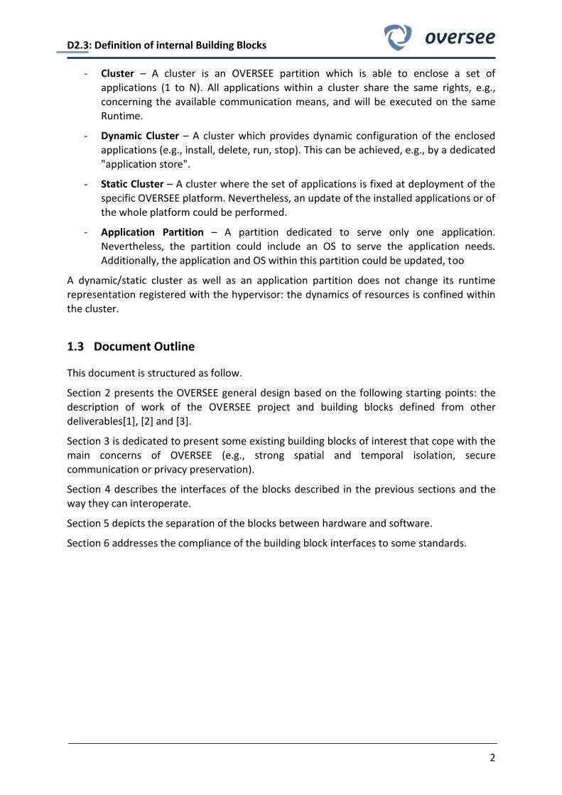
Figure 8 shows the three-layered EMVY deployment architecture consisting of (i) the hardware layer, (ii) the separation kernel layer, and (iii) on top of both the apportionable runtime environment layer that in turn executes (a) the (secure) system domain, (b) a user domain, and (c) an optional OEM domain.
The hardware layer includes the hardware devices: CPU, memory, peripherals, clocks and timers as well as secure hardware for secure key storage and secured cryptographic services, etc.
The separation kernel (or virtualization) layer provides an abstract interface of the underlying hardware resources like CPU, memory, interrupts, clock, timers and a security module. The separation kernel especially allows sharing these hardware resources (i.e., virtualization) and realizes access control enforcement on the object types known to this layer. Thus, it enforces the strong temporal and spatial partitioning of the system resources and hence is itself inherently part of the TCB.
The apportionable runtime environment layer builds on the strong (temporal and spatial) isolation of the separation kernel layer and contains the runtime environments (domains or partitions) executed in parallel where finally all the applications and/or security services are
executed. Each domain can run an individual operating system according to the respective application needs (real-time, secure real-time or general-purpose operating system). As shown in Figure 8, EMVY enables at least the following three different domains.
The system domain is the central domain for security management and security enforcement. It contains all relevant security modules and controls all relevant hardware resources by exclusively configuring all relevant policy enforcement points including the underlying separation kernel.
The user domain usually is a (lesser to be trusted) general-purpose runtime environment that allows the execution of almost arbitrary user application software.
The OEM domain is rather an example for another independent runtime environment realized and controlled for instance by an OEM or a third party having its own security and
functional requirements.
All domains, applications and modules communicate using the IPC (inter-process communication) provided and protected (i.e., confidentiality, integrity, freshness, and availability) by the underlying separation kernel.
D2.3: Definition of internal Building Blocks
22
Figure 8: EMVY deployment architecture
3.3.2 EVITA HW
Figure 9 depicts the architecture of an EVITA full size hardware security module, which generally consists of two parts, namely, (i) the cryptographic building block that realizes all cryptography hardware operations and (ii) the logic building block that connects the EVITA hardware with the (right-hand) normal ECU application core and that (i.e., the internal logic building block) optionally may execute also some cryptographic operations in software.
Figure 9: EVITA Hardware Security Module
OEM domain (optional domU)
ECU Hardware
System domain / hardware control domain (dom0/TCB)
UI
User
interface
CI
Internal
controller
interface
User domain (domU)
System application
(safety, payment, and
others)
System application
(safety, payment, and
others)
PHW
Peripheral ECU devices
(HMI, display, iDrive ..)
Separation kernel (TCB)
Real hardware drivers (storage, display, interfaces etc.) Virtual hardware drivers Virtual hardware drivers
User operating system
(UOS)
OEM operating system
(OOS)Trusted operating system (TOS)
SHW
Secure hardware
Keys Certs Counter
CCM-PEP
Communication control
module (subcomponent)
PEP(s)
Policy enforcement point(s)
IPC
PDM
Policy decision module
CCM
Comm. control module
SWD
Security watchdog module
IPC
SSM
Secure storage module
PIM
Platform integrity module
EAM
Entity authentication module
IPC
System application
(safety, payment, and
others)
System application
(safety, payment, and
others)
UAP
User application (CE
software, multimedia,
office, and others)
System application
(safety, payment, and
others)
System application
(safety, payment, and
others)
OAP
OEM and third party
application (safety,
payment, and others)
IPC
EMVY-LIB
security
interface
IPCIPC
EMVY-LIB
security
interface
DI
Developer
interface
OI
Outside
interface
Operating system interface (OSI)
Hardware interface
PEP
PEPPEP
PEP

D2.3: Definition of internal Building Blocks
23
The EVITA full hardware security module (see Figure 9: EVITA Hardware Security Module) provides the following cryptographic building blocks:
ECC-256-GF(p) is the high-performance asymmetric cryptographic engine based on a high-speed 256-bit elliptic curve arithmetic using NIST approved prime field parameters . It can generate/verify around 200 signatures per second while requiring about 2,000 slices FPGA hardware size (and usage of 32 of 48 available DSPs).
WHIRLPOOL is actually the AES-based hash function as proposed by the NIST. It has a throughput of about 1,000 Mbit/s while requiring about 3,000 slices FPGA hardware size.
AES-128 is the symmetric block encryption/decryption engine using the official NIST advanced encryption standard. It supports not only standard block encryption modes of operation such as ECB and CBC, but also advanced encryption as used, for instance, in
authenticated encryptions schemes such as GCM (Galois/Counter Mode) or CCM (Counter with CBC-MAC Mode). Our proposed implementation has a throughput of about 1,000 Mbit/s while requiring about 1,000 slices FPGA hardware size, however, almost arbitrary optimizations for size or performance are possible.
AES-PRNG is a pseudo random number generator, which is nonetheless seeded with a true random seed from a true internal physical random source. It is again based on an internal AES engine according to BSI-AIS20-E.4. Thus, throughput and size are defined by the underlying block cipher implementation. By using our AES implementation, we achieve throughputs of several hundred Mbit/s and need some additional hundred slices for the PRNG control logic.
COUNTER is a 64-bit monotonic counter function block that serves as a simple secure clock alternative. It provides at least 16 counters together with corresponding access control that
can be increased only. Each counter can be increased at least with 1 Hz while requiring about 100 slices FPGA hardware size.
Finally the EVITA full hardware security module uses an own independent internal CPU that can directly access its internal RAM and non-volatile memory to prevent any malicious interferences from the application CPU and the application software. The application CPU and its applications, however, can access the EVITA security hardware only using the secure EVITA hardware interface that enforces a well-defined access (e.g., to read-out secret keys).
Hence, for the internal processing, the full module uses the following logic building blocks.
CPU is an HSM internal CPU that can handle all logics and non-time-critical crypto-graphic functionality (e.g., high-level operations). However, it cannot be used to execute software-based cryptographic algorithms in an efficient manner. For prototyping purposes, it is a
dedicated embedded PowerPC PPC440 processor block by IBM inside the FPGA. It requires about 1,000-2000 additional slices of the FPGA to integrate it.
RAM is a small volatile memory to store for instance intermediate values and variables. It has a capacity of about at least 64 kByte and will be realized using available block RAM memory (576 kB) and available SDRAM of the evaluation board (~64 MB)
NVM is a small non-volatile memory to store for instance internal keys and security certificates. It has a capacity of about 512 kByte and will be realized using available external flash memories of the evaluation board (~16 MB).

D2.3: Definition of internal Building Blocks
24
HW-API is the secure EVITA hardware interface that enforces a well-defined access to the
EVITA hardware security functionality for the application CPU and software. It provides (with the help of the internal CPU) the message pre- and post-processing (e.g., payload extractions, padding, etc.), message/session management and message/session control.
3.4 Possible Reuse of the Existing Building Blocks
In the previous sections three building blocks from existing projects have been presented. These blocks suited the OVERSEE approach and fit perfectly with the intended design of the platform. The XtratuM and its partitions provide both spatial and temporal isolation; the SeVeCom and EVITA building blocks can ensure security and privacy in all kind of communications.
Figure 10 depicted a first resulting reuse of existing building blocks in a simplified
architecture.
Figure 10: Abstract OVERSEE Architecture based on existing building blocks from other projects
These building blocks solved some key concerns with respect to V2X capabilities:
Security of V2X communications
Privacy of V2X communications
Security of in-vehicle communications
Application interference and manipulation

D2.3: Definition of internal Building Blocks
25
3.5 Other building blocks of interest
While OVERSEE's intention is to provide security services, it at the same time shall enable reusing of existing components as well as potentially providing a future path for legacy application management in the changing environment of automotive industry.
Some of the core components we intent to evaluate and reuse at the level of proof-of-concept demonstrations are listed below. It should be noted that this not only facilitates successful reuse of potent components but also demonstrates the versatility and modularity of the OVERSEE approach.
3.5.1 OSEK/Autosar:
Though the goal of OVERSEE is not to provide a full featured system that can cover all
demands of automotive industry it is the intention to demonstrate that necessary components to amend the core capabilities of OVERSEE, focused on security, can be achieved. For this reason - and due to the dominance in the automotive industry an OSEK partition will be provided as a prototype implementation. This not only is essential to allow utilizing typical automotive software models but also to allow OVERSEE to be useful in the on-going migration from OSEK to AUTOSAR as well as the integration of legacy system components.
3.5.2 GPOS/GNU Linux:
Much interest in the past years has been on utilizing GNU/Linux in automotive applications. Navigation systems on dedicated hardware are well known. Other initiatives focus on ease of
GUI development under the typical constraints of the automotive environment. To our knowledge these initiatives do not focus, or in fact consider, security in a suitable way, thus the goal of the integration of GNU/Linux as a possible run-time-environment shall be provided as a proof-of-concept. Currently we anticipate running a MEEGO demo platform on top of OVERSEE which is one of the candidates. The overall ability of GNU/Linux with respect to communication capabilities, ranging from SMS, VoIP to Tunnel-services has the ability to broadly extend the usability of OVERSEE thus with a proof-of-concept implementation these capabilities and the possible limitations of OVERSEE can be studied.
3.5.3 ARINC 653 Communication primitives:
OSEK de-facto provides no communication primitives for interpartition communication,
AUTOSAR has the high-level architecture of the VFB (Virtual Function Bus) though conceptually the intent is to build on the VFB (architecturally) its model is not well suited for higher security integrity levels, thus a more rigorous communication primitive, based on ARINC 653, is proposed to be integrated in OVERSEE. This allows to reuse the plethora of experience gained with the ARINC 653 primitives, notably sampling and queuing ports, designed explicitly for interpartition communication. Reusing this not only at the design level, but partially at the implementation level allows to effectively advance OVERSEE.

D2.3: Definition of internal Building Blocks
26
4 Design of Interfaces between Building Blocks
The overall OVERSEE architecture will consist of different building blocks. They are described in section 2. To design the interfaces between the building blocks, the following information is needed:
- Interface declarations from task 2.1, described in D2.1[1]
- Information flow specification from task 2.2, described in D2.1[1]
- Internal communications definition from task 2.3, described in D2.2 [2]
- Building block definitions from this document, described in section 2
o Existing as well as new identified building blocks
Functional description of the building blocks
Input and output data description of the building blocks
The level of abstraction for the design of interfaces was selected with regard to existing specifications for interfaces. Most of the interfaces are well specified in existing standards and it is therefore not required to reiterate the specification here in detail.
4.1 List of Interfaces
In Figure 11 the communication paths and interfaces of the OVERSEE platform and the connected environment as well as the user land are shown. This figure is taken out of D2.2[2] and is therefore the most important input for the specification of interfaces.
All identified interfaces are collected within Table 1, Table 2, and Table 3. For each interface the endpoints and used technologies on communications, access, and protocol layer are specified.
4.1.1 Description of identified Interfaces
Each interface in Table 1, Table 2, and Table 3 is described with the following attributes:
Interface name – the name of the interface and its abbreviation.
Provider – the originating service which is accessed through this interface. Specific interfaces may be provided by multiple services, e.g., interfaces that connect two services in a bidirectional manner.
Consumer – the names of all components which are accessing a service or another component through this interface
Communication (Com) – the type of communication used for this interface. The
communication between building blocks will happen either way:
o inter-partition communication over
queuing ports (Part-Q-Port)

D2.3: Definition of internal Building Blocks
27
Figure 11: Communication paths and interfaces of OVERSEE

D2.3: Definition of internal Building Blocks
28
sampling ports (Part-S-Port)
shared memory (Part-Mem)
o inter-process communication within one partition over
shared memory
sockets (Sockets)
o exclusive hardware access
Based on/access – the underlying protocols and technologies the interface is based on.
Protocol/API – the name of the protocol and/or API used for communication on this interface respectively to access this interface. Additionally, a reference to the protocol and/or API definition and/or documentation is given.
Interface Name
Endpoints Technology
Provider Consumer Com Based on Protocol
SVAS API SVAS User part.
ITS com
Virtual NIC (Part-Mem)
TCP, XML EXLAP[10]
Virtual CAN SVAS OSEK part. Part-Q-Port Raw
forwarding App. specific
PoS API Positioning
service (PoS) User part.
A: Part-S-Port,
B: Virtual NIC (Part-Mem)
A: ASCII text,
B: TCP
Pos API specific
Bluetooth User-Access
Bluetooth manager
User part. Part-Q-Port Raw
forwarding App. specific
USB User-Access
USB device manager
User part. Part-Mem Block device App. Specific
ITS API ITS com. service
User part. Part-Q-Port Binary See 4.2.1
SecS APIs SecS User part.
ITS com Part-Q-Port See D2.2[2] See D2.2 [2]
S-MEM Secure
Memory
Provider
User part. Part-Mem Block device See D2.2 [2]
Virtual NIC IP
management User part Part-Mem
Virtual sockets
App. Specific
Table 1: OVERSEE APIs and exposed services

D2.3: Definition of internal Building Blocks
29
Interface
Name
Endpoints Technology
Provider Consumer Com Access Protocol/API
CAN CAN bus SVAS
Exclusive hardware
access
CAN CAN
Protocol
PoS HW GPS sensor PoS Serial NMEA-0183
[11]
Bluetooth HW
Bluetooth device
Bluetooth manager
Bluetooth driver
Bluetooth stack
USB HW USB device USB manager USB driver USB stack
HSM HSM SecS HSM I/O
driver EVITA [12], see D2.2 [2]
ETSI ITS-G5 ITS-G5 net ITS com. service
RF driver
ITS stack
CEN-DSRC DSRC net DSRC stack
Wi-Fi Wi-Fi net IP management
IP stack Cell 2G/3G net
HMI I/O devices
HMI and Audio management
Out of project scope Audio
Table 2: Physical and hardware interfaces
Interface Name
Endpoints Technology
Provider Consumer Com Based on Protocol
IPaC Hypervisor All Part-Q-Port Hyper call
Pos-X-Link SVAS – Pos. Service Sockets ASCII text,
NMEA 0183
POS API,
see 4.2.2
ITS-CAM-Link SVAS ITS com Sockets TCP, EXLAP SVAS API
See D2.4[3]
ITS-Crypto SecS ITS com Part-Q-Port SecS APIs, see D2.4[3]
ITS-Key-Man
Table 3: OVERSEE internal interfaces

D2.3: Definition of internal Building Blocks
30
4.2 Definition of Interfaces
Most of the interfaces mentioned in the tables above are well-known and already specified outside of our project. In the following we will concentrate therefore on the description of new interfaces respectively additional information to them.
4.2.1 ITS Communication API
Figure 12: ETSI ITS station reference architecture
A multipart standard for the service access points (SAP) will be developed within ETSI. However, this is currently not finished. Figure 12 shows the ETSI ITS station reference architecture[13] with the SAPs. Most important for our approach will be the SAP between applications and facilities layer (FA). Within OVERSEE this SAP is equivalent to the ITS communication API. Please note that an SAP description not necessarily includes an API specification, but for the purpose of this document a SAP description will be sufficient.
The adaption of the standards should be decided during the implementation depending on the standards’ release date. The ITS communication API should at least support the following features:
Subscribe to incoming Cooperative Awareness Messages (CAMs) from neighbouring cars, or observe changes of a Local Dynamic Map (LDM) that models a vehicle’s
neighbourhood.
Allow authorized partitions to set parameters that are optionally broadcasted with
CAMs (e.g., emergency lights on/off).
Subscribe to incoming Decentralized Environmental Notification Messages (DENM).
Send different types of message (e.g., DENMs) on demand of ITS applications, which are running in privileged user partitions.

D2.3: Definition of internal Building Blocks
31
Enable application to send encrypted messages over the ITS-G5 network.
Additionally CEN-DSRC should be supported:
o Subscribe to incoming CEN-DSRC messages to partitions.
o Allow authorized partitions to send CEN-DSRC messages.
4.2.2 Positioning Data Exchange Link
The Positioning Data Exchange Link (Pos-X-Link) is a very simple interface between SVAS and positioning service. The purpose of this interface is to provide positioning data, for one of the services that has no access to a positioning sensor. Hence, the information flow is always unidirectional even if the sender and receiver roles are not predetermined.
4.2.2.1 Options for Protocol and API
This section is informative only. There are multiple options to design this interface:
Reuse of SVAS API
o Advantages:
existing interface specification
o Drawbacks:
data conversion in positioning service required
complex protocol/API with many unneeded features
Reuse of PoS API
o Advantages:
existing interface specification
fits exactly the requirements
o Drawbacks:
data conversion in SVAS required
Design a new protocol from scratch
o Advantages
fits exactly the requirements
o Drawbacks
additional effort for designing the protocol
new protocol is not well-tried
data conversion on both sides required
Regarding the alternatives, reusing the PoS API is currently the favorite option.

D2.3: Definition of internal Building Blocks
32
4.2.2.2 Interface Specification
Communication on the Pos-X-Link interface is based on sockets. Information flow is unidirectional, either from SVAS to PoS or from PoS to SVAS depending on the existence of positioning sensors. As wire protocol the text-based NMEA 0183 [11] is used so that compatibility to the PoS API and PoS HW interfaces is given.
Consequently, data conversion between EXLAP and NMEA or vice versa is necessary at SVAS side. At positioning service side raw data can simply be forwarded, due to the protocol compatibility. In other words, the Pos-X-Link may take the role of the PoS HW interface or (one instance of) the PoS API interface.

D2.3: Definition of internal Building Blocks
33
5 Separation of the building blocks between HW and SW
The OVERSEE platform consists basically of the processor platform running the OVERSEE software, the external communication modules and the hardware security module. The communication modules are listed in D2.1 “List of interfaces and specifications of information flow”. The selection of the processor platform is a part of the implementation and will be discussed in D3.1 “Selection for Reuse of Existing Building Blocks”. The services and modules providing the base for the building blocks are specified in D2.2 “Specification of Security Services including Virtualization and Firewall Mechanism”. These services are software modules using the virtualization facilities of OVERSEE.
In this section we will have a short look on the EVITA hardware security module, as this is the only building block of the OVERSEE architecture realized as an external hardware block. We
will shortly list the functionality and services provided by the HSM. For further information please refer to section 3.3 and D2.2.
Figure 13: OVERSEE Exemplary Security and I/O Management Building Blocks
Services provided by the EVITA HSM:
Cryptographic services
o CMAC
o HMAC
o Signature Verification/Generation
o Random Number Generation
o Cipher

D2.3: Definition of internal Building Blocks
34
o Counter Services
Secure Key and Certificate Storage
o Access Management
o Import/Export Services
Secure/Authentic Boot Registers
Secure Clock
o Enables time stamping
o Validity check for key data

D2.3: Definition of internal Building Blocks
35
6 Building Blocks Compliance with Some Standards
In a highly diverse industry like automotive industries, with their partitioned and distributed development model, building on standards is a key qualification for any development that anticipates actually being deployed in real-life systems. Thus we briefly describe the relevant standards that have been reviewed in the context of OVERSEE.
The review has for intend to move the design and notable implementation effort into a direction that will later allow completing development in a standard compliant way where needed. At the same time basic design decisions are reviewed in the light of the individual standards so to minimize the possibility of "hard-coding" incompatibilities into the current design and implementation efforts.
6.1 Standards Overview
In the context of the on-going OVERSEE design review and beginning development a review of relevant standards has been conducted. The intention of this standard review is to define the OVERSEE mechanisms as close to accepted standards as possible - thus potentially easing later certification - and to reuse well established concepts.
6.1.1 ARINC 653
Though ARINC 653 is a widely in use avionics standard (also used in space related systems) it provides some core concepts for spatial and temporal isolation as well as communication
between isolated partitions in a manner suitable to allow composable systems. As composability is a key capability that is anticipated for OVERSEE and the mechanisms provided by ARINC 653 seem suitable for ensuring not only temporal and spatial isolation but - with adequate amendments - security, it was selected as one of the guiding standards for the detailed design and up-coming implementation phase.
Key features described in ARINC 653 relevant for OVERSEE:
Static Configuration: The configuration of the hypervisor is done via a XML
configuration file. This file defines everything from the amount of memory needed by the application and the CPU time it needs to the communication channels it is allowed to write to / read from. The XML configuration file is parsed at compile time and all the configuration data of the system is statically contained in the binary and cannot be changed during runtime. To change the configuration, the XML file has to
be edited, the binary has to be rebuilt and flashed into the target. To provide the necessary flexibility of practical systems, one can though define multiple static configurations and allow switching modes to accommodate resource allocation differences of different operation modes.
Static Scheduling: The most important property, the hypervisor has to guarantee, is the independence of the applications. We distinguish between different kinds of independence. The first one is the independence in time. This means, that a faulty application must not be able to block the CPU and therefore lead to the starvation of
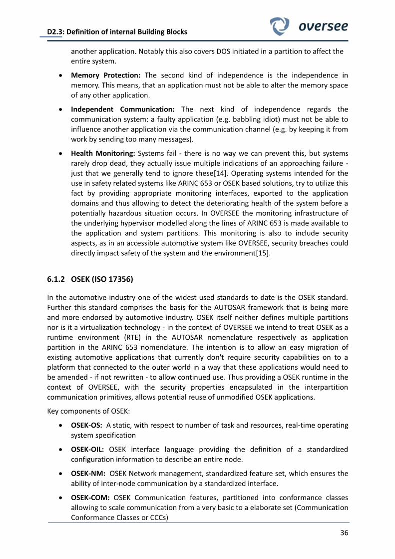
D2.3: Definition of internal Building Blocks
36
another application. Notably this also covers DOS initiated in a partition to affect the entire system.
Memory Protection: The second kind of independence is the independence in memory. This means, that an application must not be able to alter the memory space of any other application.
Independent Communication: The next kind of independence regards the
communication system: a faulty application (e.g. babbling idiot) must not be able to influence another application via the communication channel (e.g. by keeping it from work by sending too many messages).
Health Monitoring: Systems fail - there is no way we can prevent this, but systems rarely drop dead, they actually issue multiple indications of an approaching failure - just that we generally tend to ignore these[14]. Operating systems intended for the use in safety related systems like ARINC 653 or OSEK based solutions, try to utilize this
fact by providing appropriate monitoring interfaces, exported to the application domains and thus allowing to detect the deteriorating health of the system before a potentially hazardous situation occurs. In OVERSEE the monitoring infrastructure of the underlying hypervisor modelled along the lines of ARINC 653 is made available to the application and system partitions. This monitoring is also to include security aspects, as in an accessible automotive system like OVERSEE, security breaches could directly impact safety of the system and the environment[15].
6.1.2 OSEK (ISO 17356)
In the automotive industry one of the widest used standards to date is the OSEK standard. Further this standard comprises the basis for the AUTOSAR framework that is being more
and more endorsed by automotive industry. OSEK itself neither defines multiple partitions nor is it a virtualization technology - in the context of OVERSEE we intend to treat OSEK as a runtime environment (RTE) in the AUTOSAR nomenclature respectively as application partition in the ARINC 653 nomenclature. The intention is to allow an easy migration of existing automotive applications that currently don't require security capabilities on to a platform that connected to the outer world in a way that these applications would need to be amended - if not rewritten - to allow continued use. Thus providing a OSEK runtime in the context of OVERSEE, with the security properties encapsulated in the interpartition communication primitives, allows potential reuse of unmodified OSEK applications.
Key components of OSEK:
OSEK-OS: A static, with respect to number of task and resources, real-time operating
system specification
OSEK-OIL: OSEK interface language providing the definition of a standardized configuration information to describe an entire node.
OSEK-NM: OSEK Network management, standardized feature set, which ensures the
ability of inter-node communication by a standardized interface.
OSEK-COM: OSEK Communication features, partitioned into conformance classes allowing to scale communication from a very basic to a elaborate set (Communication Conformance Classes or CCCs)

D2.3: Definition of internal Building Blocks
37
Note that OSEK-ORTI is not included in ISO 17356 and is thus not mentioned here.
For the current OVERSEE project only OSEK-OS is seen as in-scope due to the project constraints. Conceptually all communication is mapped to virtual local resources and thus OSEK-NM and OSEK-COM would not be directly required in the OVERSEE context – though the OVERSEE architecture is open enough to allow for extension by providing COM/NM (i.e. as system partition) to the outer world allowing to communicate between an OVERSEE platform and an existing OSEK node.
6.1.3 AUTOSAR (AUTomotive Open System ARchitecture)
The relevance of considering AUTOSAR can be seen in the list of core-members – BMW, Bosch, Continental, Daimler, Ford, General Motors, PSA (Peugeot Citroen), Toyota, Volkswagen - who have endorsed this standard. As of July 2010 there are 46 premium
consortium members.
AUTOSAR extends the concepts introduced in OSEK to allow multiple runtime environments to co-exist on a single hardware platform. As such it is a clear fit for the OVERSEE initiative. AUTOSAR does not explicitly consider security, thus while the architectural design has been mapped to the OVERSEE structure, the internal building blocks will be shaped along ARINC 653 specifications.
Key components of AUTOSAR:
RTE: The Run-Time Environment of AUTOSAR is by definition OSEK (citation), OVERSEE extends this limitation as it is able to provide multiple side by side containers - one of which can be OSEK and thus providing an AUTOSAR compliant runtime environment.
VFB: The communication in the potentially multidomain AUTOSAR architecture is
provided by a Virtual Function Bus (VFB) that allows connecting pre-defined service providers/clients and data source/sinks in the overall system. In the OVERSEE architecture the VFB is architecturally mapped to the ARINC 653 inter-partition communication primitives - thus allowing to reuse the AUTOSAR architecture with respect to applications communicating from a OSEK-OS partition.
OS: as noted earlier the OS for AUTOSAR is OSEK (see previous section for an OSEK overview).
Conceptually the applications lie above the VFB (that is within the RTE) and the core control or basic software (BSW) is integral part of the OS. In OVERSEE the focus is on application software thus we are focused on allowing reuse of application software components (ASW) from AUTOSAR compliant products.
6.1.4 ISO 26262 Standard
While functional safety was intentionally de-scoped for the OVERSEE project, this standard is used as guidance for detailed design and implementation where possible as to achieve a platform suitable for later extension with the appropriate safety capabilities. Details of the 26262 standard are not covered here as it is formally not part of OVERSEE.

D2.3: Definition of internal Building Blocks
38
6.2 Rational for selected standards
While the focus of OVERSEE is security and, as a research project, not directly anticipating a particular application, it is clear that such a project will only gain acceptance if it also allows for a smooth migration. Thus the architectural aspects need to be modelled along existing standards widely endorsed by automotive industry to ensure that interoperability of existing components with an OVERSEE platform are feasible.
6.3 Mapping into Standards
The architectural mapping is not presented here at the technical (formal) level but rather at the qualitative level. It is well known that design incompatibilities tend to lead to subtle and hard to localize faults in complex systems, thus binding the architectural design to well
established designs at the level of the high-level architecture seems mandatory.
Figure 14: ARINC 653 -- OSEK
Figure 15: ARINC 653 -- AUTOSAR

D2.3: Definition of internal Building Blocks
39
With this qualitative mapping of the underlying standards to the OVERSEE architecture it is clear that the architectural level is potentially compatible, thus, with the extensibility of the OVERSEE architecture (i.e. by system partitions) an adaptation to existing environments and thus a mapping into an existing overall automotive architecture is feasible.
6.4 Limitations of Proof-of-concept implementation
Due to the resource constraints a full-featured implementation of OSEK is not anticipated - not only would the complexity of the full feature-set be prohibitively complex, but also the extensibility of a large code base is generally more complex than a well isolated functional subset. Further, as neither certification nor standard conformance tests are in the scope of OVERSEE, following the constraints and procedural requirements of current automotive industry practice (notably MISRA-C or IEC 26262 method catalogue) would not be possible with the time and resources available. The proof-of-concept thus is to focus on a functional minimal interface allowing to demonstrate a well defined set of scenarios only.
6.5 Interfaces compliance
Security is on the one hand based on isolation of functional units, on the other hand communication is mandatory for any real-life system, thus the mitigation of these contradictory demands is a restrictive and secure communication interface that allows enforcement of adequate security policies. To achieve such enforcement, while still achieving an acceptable performance, notably real-time performance, an efficient and fast set of basic mechanisms is necessary. These mechanisms at the same time must allow configurable and dynamic policies to be effectively imposed by providing a concise set of data channels only.
6.5.1 Interface subset
The interface subset, based on the ARINC 653 Standard[16], currently in design discussion is
sampling ports: allowing to retrieve the last valid data sample provided by the server
to this port.
queuing ports: allowing to retrieve a ordered set of data samples, up to a predefined backlog (queue-length), by a single client. If multiple clients wish to retrieve a specific data stream it is to be replicated by the serving side.
Figure 16: AUTOSAR -- OVERSEE

D2.3: Definition of internal Building Blocks
40
shared memory: not part of the OSEK/AUTOSAR nor ARINC 653 standard, though the
use-case study conducted in the context of WP1 indicate the need for a shared data mechanism allowing to communicate sparse data objects effectively.
It should be noted though that with respect to security properties the use of shared memory is problematic and thus it is not yet clear to what extent it can be used in security related applications respectively what impact the use of shared memory might have on a set of applications with different security demands resident in a single RTE. In the context of the detailed design phase preceding the implementation these issues should be clarified.
6.5.2 Technologies re-used
ARINC 653 sampling ports
ARINC 653 queuing ports
High-level architectural concepts of OSEK/AUTOSAR

D2.3: Definition of internal Building Blocks
41
7 Conclusion
From the beginning of the project some building blocks have been identified. The first part of the document provided an overview of the building blocks identified from the vision and through other deliverables ([1], [2] and [3]) of the project.
From existing project three building blocks have been identified that fit the design of the architecture and cope with main concerns of the OVERSEE project. Nonetheless, it has to be noted that they may have to be adapted and that the final selection will be performed in T3.1.
Moreover, from the identified building blocks, some propositions have been made to provide interfaces between them, and to split them in an efficient way between hardware
and software.
This document also address the compliance with some existing standard as the ITS communication architecture and ARINC 653 at the architectural level. Note we are not intending to claim compliance of OVERSEE as a whole to ARINC 653.
This document is a prerequisite of the work that will be achieved within the WP3 Task 1 named Selection for Reuse of Existing building blocks.

D2.3: Definition of internal Building Blocks
42
8 References
[1] OVERSEE Project, "D2.1 List of Interfaces and Specifications of Information Flow," December 2010.
[2] OVERSEE Project, "D2.2 Specification of security services incl. virtualization and firewall mechanism," OVERSEE FP7 Project, Deliverable 2010.
[3] OVERSEE Project, "D2.4 Specification of Secure Communication," December 2010.
[4] TECOM Consortium. Tecom Project webpage. [Online]. http://www.tecom-itea.org/
[5] OVERSEE Project. (2010) D1.4 Functional Requirements Analysis.
[6] OVERSEE Project. (2010) D1.5 Non-Functional Requirements Analysis.
[7] SEVECOM Project. SeVeCom Project website. [Online]. http://www.sevecom.org/Deliverables/Sevecom_Deliverable_D2.1_v3.0.pdf
[8] SEVECOM Project. SEVECOM : Secure Vehicle Communication. [Online]. http://www.sevecom.org/
[9] OVERSEE Consortium, "D1.1 Use Case Analysis," OVERSEE Project, FP7 OVERSEE Project Deliverable 2010.
[10] http://www.exlap.de
[11] NMEA 0183 standard V4.00.
[12] Evita Project. (2011, January) EVITA. http://www.evita-project.org.
[13] ETSI, "EN 302 605 V1.1.1 Intelligent Transport Systems (ITS) : Communication Architecture," September 2010.
[14] Charles Perrow, Normal Accident: Living with High Risk Technologies., September 1999.
[15] Ishtiaq Roufa and Rob et al. Miller, "Security and Privacy Vulnerabilitis of In-Car Wireless Networks : A Tire Pressure Monitoring System Case Study," 2010, http://www.usenix.org/events/sec10/tech/full_papers/Rouf.pdf.
[16] "Avionics Application Software Standard Interface, ARINC Specification 653," 1997.