D2.2.1 Requirement document (Document id. :...
57
D2.2.1 Requirements Document DURAARK FP7 – ICT – Digital Preservation Grant agreement No.: 600908 Date: 2013-07-27 Version 1.0 Document id. : duraark/2013/D.2.2.1/v1.0
Transcript of D2.2.1 Requirement document (Document id. :...

D2.2.1 Requirements Document
DURAARK
FP7 – ICT – Digital Preservation
Grant agreement No.: 600908
Date: 2013-07-27
Version 1.0
Document id. : duraark/2013/D.2.2.1/v1.0
Deliverable Name
DuraArkFP7 – ICT – Digital Preservation
Grant agreement No.: 600908
Date: 201x-MM-DD
Version 1.x
Document id. : duraark/201x/D.X.X/v1.x

D2.2.1 Requirement Document| Page 1 of 56
Grant agreement number : 600908
Project acronym : DURAARK
Project full title : Durable Architectural Knowledge
Project’s website : www.duraark.eu
Partners : LUH – Gottfried Wilhelm Leibniz Universitaet Hannover (Coordinator) [DE]
UBO – Rheinische Friedrich-Wilhelms-Universitaet Bonn [DE]
FhA – Fraunhofer Austria Research GmbH [AT]
TUE – Technische Universiteit Eindhoven [NL]
CITA – Kunstakademiets Arkitektskole [DK]
LTU – Lulea Tekniska Universitet [SE]
Catenda – Catenda AS [NO]
Project instrument : EU FP7 Collaborative Project
Project thematic priority : Information and Communication Technologies (ICT) Digital Preservation
Project start date : 2013-02-01
Project duration : 36 months
Document number : duraark/2013/D.2.2.1
Title of document : D2.2.1 Requirement document
Deliverable type : Report
Contractual date of delivery : 2013-07-31
Actual date of delivery : 2013-07-31
Lead beneficiary : LUH
Author(s) : Jakob Beetz <[email protected]> (TUE),
Rene Berndt <[email protected]> (FhA),
Stefan Dietze <[email protected]> (LUH),
Dag Fjeld Edvardsen <[email protected]> (Catenda),
Ujwal Gadiraju <[email protected]> (LUH),
Michelle Lindlar <[email protected]> (LUH),
Sebastian Ochmann <[email protected]> (UBO),
Martin Tamke <[email protected]> (CITA),
Richard Vock <[email protected]> (UBO).
DURAARKFP7 – ICT – Digital PreservationGrant agreement No.: 600908

D2.2.1 Requirement Document| Page 2 of 56
Responsible editor(s) : Michelle Lindlar <[email protected]> (LUH).
Quality assessor(s) : Mohammad Alrifai <[email protected]> (L3S),
Ernesto Diaz-Aviles <[email protected]> (L3S),
Osten Jonsson <[email protected]> (LTU),
Raoul Wessel <[email protected]> (UBO).
Approval of this deliverable : Stefan Dietze <[email protected]> (LUH) – Project Coordinator
Distribution : Public
Keywords list : use cases, user requirements
DURAARKFP7 – ICT – Digital PreservationGrant agreement No.: 600908

D2.2.1 Requirement Document| Page 3 of 56
Executive Summary
This document presents the DURAARK stakeholders’ requirements for the long-term
preservation of digital 3D architectural data. Based on the different stakeholders and
various use cases the functional requirements as well as the non-functional requirements
are derived. This deliverable will serve as the foundation for evolving the system archi-
tecture of DURAARK in the deliverables D2.2.2 and D2.2.3.
DURAARKFP7 – ICT – Digital PreservationGrant agreement No.: 600908

Table of Contents
1 Introduction . . . . . . . . . . . . . . . . . . . . . . . . . . . . . . . . . . 7
2 Motivation . . . . . . . . . . . . . . . . . . . . . . . . . . . . . . . . . . . 11
2.1 The different phases in a building’s life-cycle . . . . . . . . . . . 11
2.2 Information exchange between the phases and actors . . . . . . . 11
2.3 No two projects are the same . . . . . . . . . . . . . . . . . . . . 12
2.4 Example: Renovation of the Nørreport station in Copenhagen . . 13
2.5 The resulting need for DURAARK . . . . . . . . . . . . . . . . . 16
3 Stakeholders . . . . . . . . . . . . . . . . . . . . . . . . . . . . . . . . . . 18
4 Use cases . . . . . . . . . . . . . . . . . . . . . . . . . . . . . . . . . . . 23
4.1 UC1: Deposit 3D architectural objects. . . . . . . . . . . . . . . . 25
4.2 UC2: Search and retrieve archived objects. . . . . . . . . . . . . . 27
4.3 UC3: Maintain semantic digital archive. . . . . . . . . . . . . . . 29
4.4 UC4: Detect differences between planning and as-built state . . . 32
4.5 UC5: Monitor the evolution of a structure over time. . . . . . . . 35
4.6 UC6: Identify similar objects within a point-cloud scan. . . . . . . 37
4.7 UC7: Plan, document and verify retrofitting/energy renovation of
buildings. . . . . . . . . . . . . . . . . . . . . . . . . . . . . . . . 40
4.8 UC8: Exploit contextual information for urban planning . . . . . 43
4

D2.2.1 Requirement Document| Page 5 of 56
4.9 UC9: Enrich a BIM/IFC model with metadata from a repository. 45
5 Functional and non-functional requirements . . . . . . . . . . . . . . . . 48
5.1 Functional Requirements . . . . . . . . . . . . . . . . . . . . . . . 49
5.2 Non-functional Requirements . . . . . . . . . . . . . . . . . . . . 54
6 Conclusion . . . . . . . . . . . . . . . . . . . . . . . . . . . . . . . . . . . 55
References . . . . . . . . . . . . . . . . . . . . . . . . . . . . . . . . . . . . . . 56
DURAARKFP7 – ICT – Digital PreservationGrant agreement No.: 600908

D2.2.1 Requirement Document| Page 6 of 56
DURAARKFP7 – ICT – Digital PreservationGrant agreement No.: 600908

D2.2.1 Requirement Document| Page 7 of 56
1 Introduction
The overall goal of the DURAARK project is the development of tools and methods for
sustainable long-term preservation of architectural 3D data. It will exploit state of the art
semantic web technologies to ensure consistency, reliability, and future-proof reusability
of archived data. Additionally, it will for the first time cover and exploit the complete
spectrum of representations used for architectural information, ranging from low-level 3D
point-clouds up to highly annotated 3D BIM models and semantic metadata.
“Long-term preservation” is never a promise of safe guarding objects for five or fifty years,
but rather a promise to develop strategies which meet the constant change imposed
on digital objects and their surroundings through the fast-paced development of new
technologies [6]. Digital long-term preservation in general deals with three basic aspects:
• Bit Preservation addresses the issue of preserving the unaltered digital data
stream, e.g., by separating objects from heterogeneous sources and different data
carriers as soon as possible and by moving objects into a homogeneous storage
system.
• Logical Preservation denotes the interpretation of data, e.g., through an oper-
ating system and applications. It requires an according infrastructure as well as a
strategy of how to keep data accessible AND usable. The features which are signif-
icant for future usage highly depend on the targeted user groups. Guranteeing the
logical sustainability of an object is a more complicated task than the preservation
of the bitsream alone.
• Semantic Preservation addresses the issue of the understandability of the in-
formation content within the object as concepts or terminology change over time
[5].
Within the DURAARK project all three aspects are addressed for architectural 3D data,
e.g., bit preservation by ingesting the objects into an OAIS1 compliant digital preser-
vation system, logical preservation by extending the Industry Foundation Classes (IFC)
data model2 towards an archival IFC/A model and by capturing extensive technical
1http://public.ccsds.org/publications/archive/650x0m2.pdf2http://www.buildingsmart.org/
DURAARKFP7 – ICT – Digital PreservationGrant agreement No.: 600908
D2.2.1 Requirement Document| Page 8 of 56
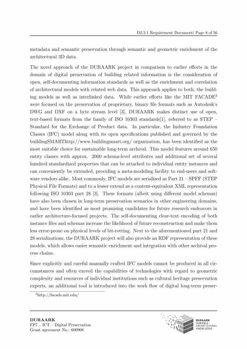
metadata and semantic preservation through semantic and geometric enrichment of the
architectural 3D data.
The novel approach of the DURAARK project in comparison to earlier efforts in the
domain of digital preservation of building related information is the consideration of
open, self-documenting information standards as well as the enrichment and correlation
of architectural models with related web data. This approach applies to both, the build-
ing models as well as interlinked data. While earlier efforts like the MIT FACADE3
were focused on the preservation of proprietary, binary file formats such as Autodesk’s
DWG and DXF on a byte stream level [3], DURAARK makes distinct use of open,
text-based formats from the family of ISO 10303 standards[1], referred to as STEP –
Standard for the Exchange of Product data. In particular, the Industry Foundation
Classes (IFC) model along with its open specifications published and governed by the
buildingSMARThttp://www.buildingsmart.org/ organization, has been identified as the
most suitable choice for sustainable long-term archival. This model features around 650
entity classes with approx. 2000 schema-level attributes and additional set of several
hundred standardized properties that can be attached to individual entity instances and
can conveniently be extended, providing a meta-modeling facility to end-users and soft-
ware vendors alike. Most commonly, IFC models are serialized as Part 21 – SPFF (STEP
Physical File Formats) and to a lesser extend as a content-equivalent XML representation
following ISO 10303 part 28 [3]. These formats (albeit using different model schemas)
have also been chosen in long-term preservation scenarios in other engineering domains,
and have been identified as most promising candidates for future research endeavors in
earlier architecture-focused projects. The self-documenting clear-text encoding of both
instance files and schemas increase the likelihood of future reconstruction and make them
less error-prone on physical levels of bit-rotting. Next to the aforementioned part 21 and
28 serializations, the DURAARK project will also provide an RDF representation of these
models, which allows easier semantic enrichment and integration with other archival pro-
cess chains.
Since explicitly and careful manually crafted IFC models cannot be produced in all cir-
cumstances and often exceed the capabilities of technologies with regard to geometric
complexity and resources of individual institutions such as cultural heritage preservation
experts, an additional tool is introduced into the work flow of digital long-term preser-
3http://facade.mit.edu/
DURAARKFP7 – ICT – Digital PreservationGrant agreement No.: 600908

D2.2.1 Requirement Document| Page 9 of 56
vation of buildings. Currently, possibilities to survey buildings using photogrammetric
methods and laser scans resulting in high-resolution point-clouds become increasingly
affordable and usable. Although the outward appearance of buildings can be captured
at high precision using these technologies, the resulting data sets are semantically weak,
i.e., individual sets of points are not associated with the respective components (walls,
doors, windows, etc.) they describe. To overcome this, the DURAARK project facilitates
the semantic enrichment of these data sets by object and feature detection mechanism
and will partially generate semantic structures in semi-automatic fashions. If explicit
models in the form of IFC instances are present, these will be associated to the respective
entity instances, providing an additional form of shape representation next to the tra-
ditional CSG, BREP or polygonal geometries commonly used to model buildings. The
DURAARK project will extend the IFC model to enable such additional point-cloud ge-
ometries and will submit it for standardization to the buildingSMART standardization
organization.
The first step in any software development activitiy is the planning process. The planning
process builds on a clear motivation for the activity and starts with the defintion of
stakeholders, which are persons or entities with an interest in the outcome of the project.
The stakeholders in return formulate requirements in the system. These requirements
can be further differentiated into functional and non-functional requirements. While
functional requirements describe what a system is supposed to do (“system must do
<requirement>”), non-functional requrirements describe how a system is supposed to
be (“system shall be <requirement>”). Requirements should be objective and testable
while outlining the behavior of the system as envisioned by the stakeholders.
The motivation for the DURAARK project is briefly presented in Section 2 of this de-
liverable. It formed the basis for the stakeholder analysis and definition, as presented in
Section 3. The approach chosen is based on the Unified Process [2], where use cases will
aid the outlining of key requirements and serve as the information basis for the component
definitions in the “System Architecture and Specification” (D2.2.2). The use case tem-
plate itself, as presented in Section 4, is based on the Open Unified Process (OpenUP)4,
which in return is part of the Eclipse Process Framework. In a first step, ideas for use
cases were collected in brainstorming meetings. In a second step the aforementioned tem-
plate was provided and the use cases were further defined in stakeholder interviews and
4http://epf.eclipse.org/wikis/openup/
DURAARKFP7 – ICT – Digital PreservationGrant agreement No.: 600908

D2.2.1 Requirement Document| Page 10 of 56
small group discussions. After several iterations the use cases were refined as presented
and Section 4 and formed the basis for the requirement extraction presented in Sections
5.1 and 5.2.
DURAARKFP7 – ICT – Digital PreservationGrant agreement No.: 600908
D2.2.1 Requirement Document| Page 11 of 56
2 Motivation
2.1 The different phases in a building’s life-cycle
How construction projects are organized differs from country to country. There are also
big differences in the organization based on size and other parameters. The different
main groups of activities that are carried out are however mainly the same.
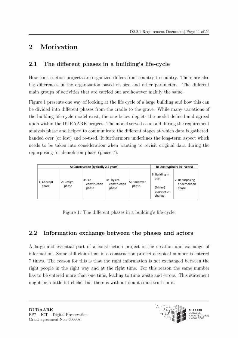
Figure 1 presents one way of looking at the life cycle of a large building and how this can
be divided into different phases from the cradle to the grave. While many variations of
the building life-cycle model exist, the one below depicts the model defined and agreed
upon within the DURAARK project. The model served as an aid during the requirement
analysis phase and helped to communicate the different stages at which data is gathered,
handed over (or lost) and re-used. It furthermore underlines the long-term aspect which
needs to be taken into consideration when wanting to revisit original data during the
repurposing- or demolition phase (phase 7).
A: Construction (typically 2.5 years) B: Use (typically 60+ years)
6: Building in use
1: Concept phase
2: Design phase
3: Pre‐ construction phase
4: Physical construction phase
5: Handover phase (Minor)
upgrade or change
7: Repurposing or demolition phase
Figure 1: The different phases in a building’s life-cycle.
2.2 Information exchange between the phases and actors
A large and essential part of a construction project is the creation and exchange of
information. Some still claim that in a construction project a typical number is entered
7 times. The reason for this is that the right information is not exchanged between the
right people in the right way and at the right time. For this reason the same number
has to be entered more than one time, leading to time waste and errors. This statement
might be a little bit cliche, but there is without doubt some truth in it.
DURAARKFP7 – ICT – Digital PreservationGrant agreement No.: 600908
D2.2.1 Requirement Document| Page 12 of 56
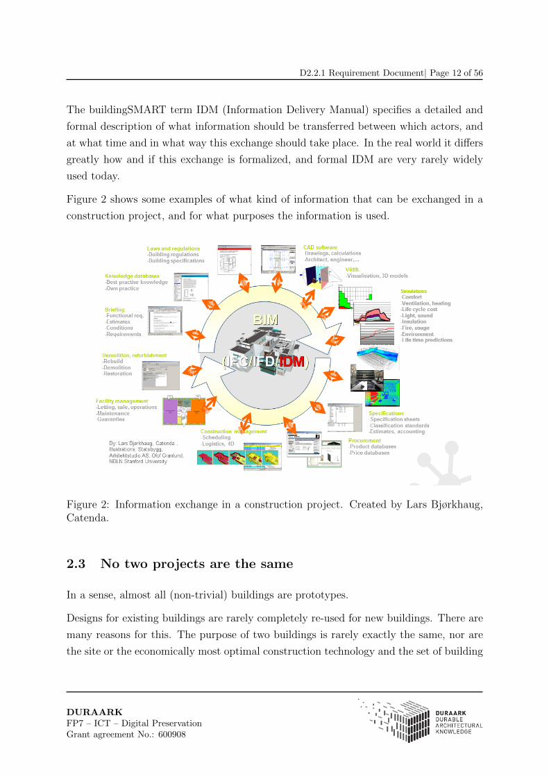
The buildingSMART term IDM (Information Delivery Manual) specifies a detailed and
formal description of what information should be transferred between which actors, and
at what time and in what way this exchange should take place. In the real world it differs
greatly how and if this exchange is formalized, and formal IDM are very rarely widely
used today.
Figure 2 shows some examples of what kind of information that can be exchanged in a
construction project, and for what purposes the information is used.
Figure 2: Information exchange in a construction project. Created by Lars Bjørkhaug,Catenda.
2.3 No two projects are the same
In a sense, almost all (non-trivial) buildings are prototypes.
Designs for existing buildings are rarely completely re-used for new buildings. There are
many reasons for this. The purpose of two buildings is rarely exactly the same, nor are
the site or the economically most optimal construction technology and the set of building
DURAARKFP7 – ICT – Digital PreservationGrant agreement No.: 600908
D2.2.1 Requirement Document| Page 13 of 56
components identical. In addition, for non-trivial buildings the companies that cooperate
are rarely the same.
The effect is that even though there are dominant standards and well known practices,
very few non-trivial construction projects are repeated. This makes the overall data
gathered during the construction phase as well as during minor upgrades and repurposing
steps within the use phase (see Figure 1) unique data which cannot be fully reproduced
if lost.
2.4 Example: Renovation of the Nørreport station in Copen-
hagen
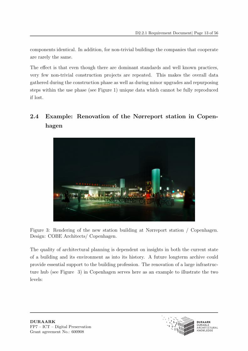
Figure 3: Rendering of the new station building at Nørreport station / Copenhagen.Design: COBE Architects/ Copenhagen.
The quality of architectural planning is dependent on insights in both the current state
of a building and its environment as into its history. A future longterm archive could
provide essential support to the building profession. The renovation of a large infrastruc-
ture hub (see Figure 3) in Copenhagen serves here as an example to illustrate the two
levels:
DURAARKFP7 – ICT – Digital PreservationGrant agreement No.: 600908

D2.2.1 Requirement Document| Page 14 of 56
Gathering insights into the history of a building
Insights into the history of a building are today gathered through the collection of archi-
tectural data from archives, building owners and publicly available sources. In a following
process architects are trying to identify the evolution of a building. As historic plans are
often not complete or of bad quality a type of building forensic is necessary. This holds
especially true in cases like the renovation of the Nørreport station in Copenhagen. This
400 meter long central station is underneath one of the busiest squares in the Danish
capital. As it was built 1918 (see Figure 4) several intermediate states had to be re-
constructed in order to find out how renovation work of the concrete structure could be
carried out. The combination of geolocated historic material from the last 100 years as
plans, sections, but as well photos with 3D point-cloud data allowed the engineers to
understand the location of old foundations and other obstacles as well as to generate an
understanding of the positioning of the tunnel in relation to the contemporary surface of
the square above.
Figure 4: The beginnings of the Nørreport in 1913.
DURAARKFP7 – ICT – Digital PreservationGrant agreement No.: 600908
D2.2.1 Requirement Document| Page 15 of 56
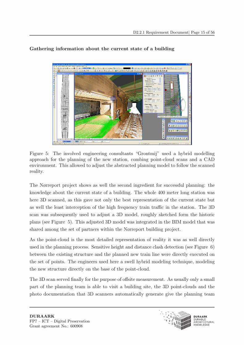
Gathering information about the current state of a building
Figure 5: The involved engineering consultants “Grontmij” used a hybrid modellingapproach for the planning of the new station, combing point-cloud scans and a CADenvironment. This allowed to adjust the abstracted planning model to follow the scannedreality.
The Nørreport project shows as well the second ingredient for successful planning: the
knowledge about the current state of a building. The whole 400 meter long station was
here 3D scanned, as this gave not only the best representation of the current state but
as well the least interception of the high frequency train traffic in the station. The 3D
scan was subsequently used to adjust a 3D model, roughly sketched form the historic
plans (see Figure 5). This adjusted 3D model was integrated in the BIM model that was
shared among the set of partners within the Nørreport building project.
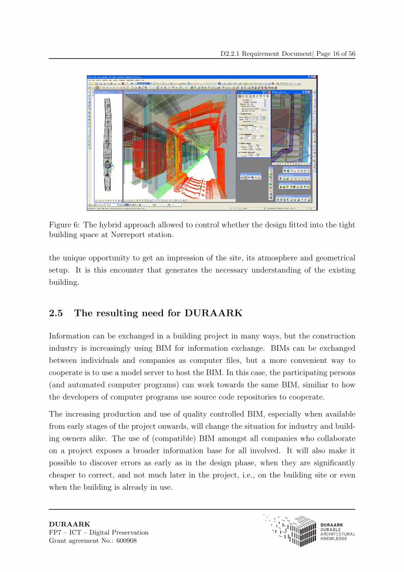
As the point-cloud is the most detailed representation of reality it was as well directly
used in the planning process. Sensitive height and distance clash detection (see Figure 6)
between the existing structure and the planned new train line were directly executed on
the set of points. The engineers used here a swell hybrid modeling technique, modeling
the new structure directly on the base of the point-cloud.
The 3D scan served finally for the purpose of offsite measurement. As usually only a small
part of the planning team is able to visit a building site, the 3D point-clouds and the
photo documentation that 3D scanners automatically generate give the planning team
DURAARKFP7 – ICT – Digital PreservationGrant agreement No.: 600908
D2.2.1 Requirement Document| Page 16 of 56
Figure 6: The hybrid approach allowed to control whether the design fitted into the tightbuilding space at Nørreport station.
the unique opportunity to get an impression of the site, its atmosphere and geometrical
setup. It is this encounter that generates the necessary understanding of the existing
building.
2.5 The resulting need for DURAARK
Information can be exchanged in a building project in many ways, but the construction
industry is increasingly using BIM for information exchange. BIMs can be exchanged
between individuals and companies as computer files, but a more convenient way to
cooperate is to use a model server to host the BIM. In this case, the participating persons
(and automated computer programs) can work towards the same BIM, similiar to how
the developers of computer programs use source code repositories to cooperate.
The increasing production and use of quality controlled BIM, especially when available
from early stages of the project onwards, will change the situation for industry and build-
ing owners alike. The use of (compatible) BIM amongst all companies who collaborate
on a project exposes a broader information base for all involved. It will also make it
possible to discover errors as early as in the design phase, when they are significantly
cheaper to correct, and not much later in the project, i.e., on the building site or even
when the building is already in use.
DURAARKFP7 – ICT – Digital PreservationGrant agreement No.: 600908

D2.2.1 Requirement Document| Page 17 of 56
From the perspective of the DURAARK project, long-term availability of this essential
information captured in a BIM can give valuable insight about the construction. Fur-
thermore, it supplements the surface data provided by a point-cloud in important ways.
It can tell us about hidden constructions and provide detailed information about the
building components.
The example of the Nørreport project shows the value of historic and current architectural
data alike. While in the case of Nørreport the reconstruction of prior building states was
a resource intensive task, a future archive for digital architectural data, as proposed by
the DURAARK consortium, would ease the work of planners by allowing the overlay
of all relevant data from different periods of a building. The combination of this data
in an IFC model would generate an easy interface from the future longterm archive
to the planning tools of the building profession. Here the users of a future longterm
archive should browse through different historic states of the building, where an interface
would highlight differences and changes between theses states, allowing the user a base
to understand the reasons and decisions for the evolution of a building.
Furthermore, a holistic data approach, including different media types and sources, may
also form the basis for a successful implementation of planning, as it enables everyone to
get a feel for the site without having necessarily visited it. It is hence important that a
longterm archive is able to provide access to combined data from different media types,
sources and times and to automate the repetitive processes that enable the generation of
models for architectural planning.
DURAARKFP7 – ICT – Digital PreservationGrant agreement No.: 600908

D2.2.1 Requirement Document| Page 18 of 56
3 Stakeholders
While nowadays archiving of architectural data predominately describes the act of storing
and protecting an asset over a long-time and giving the user means to find and retrieve it,
the potential of digital archives reaches far beyond this practise. The potential to query
and connect search results within different classes of metadata of a single building, as
well as across a set of regionally or typologically similar buildings widens the potential
set of stakeholders of the proposed archive for architectural data in comparison to com-
parable contemporary archives. Nowadays, architectural archives are typically located
at different levggels within municipalities, institutions or companies and serve mainly
internal functions or specialist groups within the building profession. The DURAARK
architecture proposes to hold architectural data of a wide technical spectrum, specifically
pointclouds as well as IFC files, while offering the possibility for in depth query through a
rich set of metadata. Due to this it can be expected that in the future a long-term archive
of architectural data on municipal planning, building control office, office or library with
a collection focus on architecture, subsequently referred to as DURAARK archive, can
give access to a broader set of stakeholders including actors from the public who usually
don’t have access to or interest in an architectural archive. A further important assump-
tion for the definition of DURAARK stakeholders is the DURAARK archive’s ability to
visualize query results for the users. Architectural data can hold many different types
of non-textual data that are not directly ready for interpretation by an observer. This
applies especially to the field of queries between representations of a building at different
stages of time, which is today a quite time consuming effort for stakeholders. Where this
is a basic motivation that is shared by all users, the specific interests of particular user
groups towards long-term archived architectural data largely differ.
• Architects and Engineers Architects and engineers are both producer and con-
sumer of archived architectural data: while they consume architectural data as a
base for their planning activities, they also want to long-term archive the data they
create. As data consumers, architects and engineers query a DURAARK archive
in order to find information about a building’s history and the changes it has un-
dergone (see phases 6 and 7, Figure 1). Their focus depends on the job that
is underlying their search and might vary from an investigation into the original
construction of a building, from which they can derive the intention of the orig-
DURAARKFP7 – ICT – Digital PreservationGrant agreement No.: 600908
D2.2.1 Requirement Document| Page 19 of 56
inal author, to the investigation of the urban context of a potential building site
or the assessment of the current state in spatial and construction related areas of
the building represented through a relatively up to date 3D scan. As the plan-
ning of buildings is done on an abstraction of reality, architects will typically ask
for an abstracted model that represents the state of a building. Such models are
typically-polygon-based and stored in IFC format. A mechanism to derive these
models from 3D point-clouds, as well as an indication on the deviations from the
real geometry will allow architects to start their planning directly from the archived
data. The enrichment of this data through existing data from previous planning
states is expected to have a positive impact on the planning precision, not at least
for the improvements of the energy use of building structures.
Architects and engineers are as well commissioned to monitor and evaluate the
state of a building in order to detect damages and the cause and speed of their
progression. Archived descriptions of single buildings and aggregations are of high
value here, and the tracking of changes, caused for instance through underground
building works or degradation of building elements, is directing the engineers’ rec-
ommendations. As engineers and architects are the main producers of architectural
data it can be expected that they will install or use long-term-archiving systems
for their own companies’ architectural data (see phases 1 and 2, Figure 1). The
motivation for this might be to document and secure the data that describes a
project delivered for the period of liability, but as well the ingest into the compa-
nies’ archive that is in bigger offices usually more directed towards public relations,
acquisition and internal knowledge management. Engineering companies are usu-
ally bigger than those of architects, making the installation of long-term archiving
systems even more probable.
Related use cases: UC1, UC2, UC4, UC5, UC6, UC7, UC8, UC9
• Construction companies
Like architects and engineers, construction companies can be both producer and
consumer of archived architectural data. They predominately produce highly de-
tailed and annotated architectural data in the later stages of a building project
(see phases 3 and 4, Figure 1). However, they also consume previous records
of the building they are working on for evaluation purposes. During the often
years-lasting building projects, construction companies produce vast amounts of
DURAARKFP7 – ICT – Digital PreservationGrant agreement No.: 600908

D2.2.1 Requirement Document| Page 20 of 56
architectural data which needs to be stored during the process of the project and
beyond. This especially holds true as the construction companies, as the last part
in the design to production chain, are today starting to utilize the full potential of
building information models with architectural objects with rich metadata. Here
the level of detailing is increasing and besides the modelling of very small objects in
BIM models (from 5mm onwards), especially the integration of external catalogues
is of importance. Such catalogues hold information about products from building
vendors. The increasing specifications in BIM models are becoming part of the
business model of construction companies. As consumers, the access to a long-term
archive will help construction companies with questions regarding measurements in
existing parts of a building. The comparison of recent scans of an ongoing building
project with those that are stored in the long-term archive will allow them to track
the building process, e.g., see whether tolerances are met and building elements are
installed in time.
As building companies are today transnational they will have a natural interest to
build up their own long-term archiving systems, especially as they are most aware
of the legal aspects of their work.
Related use cases: UC1, UC2, UC4, UC7, UC9
• Researchers and Lawyers
Researchers and lawyers represents consumers of architectural data from an archive
like the one proposed here. Their interest spans over the entire lifecycle of an ob-
ject (see phases 1 through 7, Figure 1). They are typically both interested in the
archived descriptions of either a particular building, an agglomeration of buildings
or a group of buildings. Criteria for a retrieval request can here be buildings of from
the building period, architect, location, type or use. Both researchers and lawyers
are interested in understanding the responsibilities and line of decisions that caused
a damage or flaw in a building or building process. Lawyers will typically want ac-
cess to all data available that can demonstrate the change of a building over time
and the building documentation that was produced in the specific period queried.
Researchers and lawyers will furthermore make extensive use of the extended infor-
mation level within BIM data and enriched data from 3D scans and query within
this data for instance for similar elements, trace decisions or trace the development
of building elements over time. Here a combined search in BIM and 3D scan data
DURAARKFP7 – ICT – Digital PreservationGrant agreement No.: 600908
D2.2.1 Requirement Document| Page 21 of 56
is necessary and will provide new possibilities for forensic research.
Researchers may also be interested in atmosphere and materiality of a building at
a certain time, where they will query for image or coloured 3D scan data.
Related use cases: UC1, UC2, UC4, UC6
• Building Owners and Real Estate Managers
Building owners and real estate managers are consumers of architectural data
(mainly phases 2-7, Figure 1). Different scenarios exist, where archived archi-
tectural data is of high use to this group. When intending to retrofit a buidling
or when planning to erect a new building on the premises at their hand, building
owners and real estate managers usually address a municipal planning and building
control office or a library with a collection mandate with a request for stored data.
Furthermore, when intending to sell a particular real estate, additional documen-
tation of the buildings’ history may be needed in order to assess its value. Risk
assessment based on previous changes to the structure of a building as well as eval-
uating the potential to easily extend or refit a building are further interests specific
to this group of stakeholders. Related use cases: UC1, UC2, UC4, UC5, UC6,
UC7
• Public Administrations/ Public Planning / Policy Makers
Public administrations have a wide range of orders that are placed in the planning
sector as well as in the mandate to collect architectural data. As such they can be
considered consumers with a similar profile as architects and engineers, as well as
producers of architectural data. Municipalities and other institutions are realizing
the potential of the set of extended architectural data for their internal planning
processes as well as for satisfying the increasing demand of their clients. Hence
they are increasingly demanding IFC models as representations of buildings within
building applications. As they have a rich set of metadata they are well suited to
answer information requests from stakeholders involved in the planning on larger or
urban scale projects that stretch over a large number of buildings or areas of a city.
Examples for such requests include information on the average room height within
a new built area, on the average window size or the amount of grass covered. As
this data stems from a planning state (typically phases 2 through 4, Figure 1) an
institutional user will have an interest in comparing this data with the real state,
as represented in 3D scans. These queries refer to the current state as well as to
DURAARKFP7 – ICT – Digital PreservationGrant agreement No.: 600908

D2.2.1 Requirement Document| Page 22 of 56
historic data. Trends can be detected by comparing sets of data from different
times.
Related use cases: UC2, UC5, UC8
• Knowledge base maintainers
Knowledge base maintainers are producers of architectural data, as they gather
information from external sources and make them available to various actors (e.g.,
building industry practitioners, librarians, researchers). Information sources vary
from technical information such as classification systems for building artifacts, prod-
uct libraries, building regulation codes, structured vocabularies etc. to cultural-
oriented data such as the geographical context of buildings, social networks of users,
historic information or art-historic data about building styles etc. The knowledge
base provider maps these data sources into an ontological framework and makes
them accessible through a uniform interface to allow actors to enrich their building
data.
Related use cases: UC2, UC3, UC9
• Cultural Heritage Institutions
Cultural heritage institutions are consumers of architectural data. Their task is to
gather, preserve and grant access to the data specified in their collection profile.
Cultural heritage institutions include libraries, archives and museums at national,
state or institutional level. They are often responsible for information that has left
the domain of industrial interest and needs to be preserved as part of the cultural
heritage of a specific country or region. Many cultural heritage institutions have
a clear archival mandate, often specifying the collection of material regardless of
publication form. The institutions have found themselves facing a growing amount
of such digital heritage since the turn of the millennium. The UNESCO Charter
on the Preservation of Digital Heritage (2003) defines the term “digital heritage”
as “unique resources of human knowledge and expression” which must be made
accessible while simultaneously respecting copyright and privacy rights[4]. To meet
this goal, it is necessary to develop and implement standards and strategies for
digital preservation. As such it can be expected that cultural heritage institution
will maintain long-term archiving systems containing architectural data.
Related use cases: UC1, UC2, UC9
DURAARKFP7 – ICT – Digital PreservationGrant agreement No.: 600908
D2.2.1 Requirement Document| Page 23 of 56
4 Use cases
This section describes a total of 9 use cases addressing creation and consumption of digital
3D architectural data focusing on the long-term preservation aspects.
As part of the use case definition, three actors were identified as persons or external sys-
tems interacting with the DURAARK system. The actor common to all use cases is the
user. The user can be an instance of any stakeholder defined in chapter 3 who uses the
DURAARK system to process data or query the system. Each use case contains an Ac-
tors segment, in which the respective stakeholders are matched to the users pertaining to
the specific use case. Besides the user two external systems interact with the DURAARK
system: the digital preservation system and an external knowledge base. While long-term
archiving tasks are at the core of all DURAARK processes and tools, the storage and
data administration layer is provided through an external digital preservation system.
All data is physically stored there and subsequently all use cases interact with the digital
preservation system. Thus all use cases can be regarded as extensions of the meta use
cases “UC1: Deposit 3D architectural objects” and “UC2: Search and retrieve archived
objects”. The exception to this is “UC3: Maintain Semantic Digital Archive”, which is
a meta use case itself. It describes the maintenance of the DURAARK system internal
semantic digital archive, which in retrospect use cases UC8 and UC9 are extensions of.
Core long-term preservation
• UC1: Deposit 3D architectural objects
• UC2: Search and retrieve archived objects
• UC3: Maintain Semantic Digital Archive
Production/Consumption
• UC4: Detect differences between planning state and as-built state
• UC5: Monitor the evolution of a structure over time
• UC6: Identify similar objects within a point-cloud scan
• UC7: Plan, document and verify retrofitting/energy renovations
• UC8: Exploit contextual information for urban planning
• UC9: Enrich BIM/IFC model with metadata from a repository
DURAARKFP7 – ICT – Digital PreservationGrant agreement No.: 600908

D2.2.1 Requirement Document| Page 24 of 56
User
UC 2:
Search and retrieve
archived objects
UC 4:
Detect differences between
planning and as-built state
UC 3:
Maintain semantic
digital archive
UC 5:
Monitor the evolution of a
structure over tme
UC 6:
Identify similar objects
within a point cloud scan
UC 7:
Plan, document and verify
retrofitting/energy
renovations
UC 8:
Exploit contextual
information for urban
planning
UC 9:
Enrich BIM/IFC model with
metadata from a repository
UC 1:
Deposit 3D
architectural
objects
Digital preservation
system (DPS)
External knowledge base
DURAARK system
Figure 7: Use cases in the DURAARK system. UC 1, 2 and 3 denote the “meta usecases”.
DURAARKFP7 – ICT – Digital PreservationGrant agreement No.: 600908
D2.2.1 Requirement Document| Page 25 of 56
4.1 UC1: Deposit 3D architectural objects.
1 Description
This use case describes the deposit of 3D architectural objects into an existing
digital preservation system (DPS). The outcome of the use-case is a submission
information package (SIP) which can be ingested into the DPS. The main actor
is any stakeholder who wants to keep objects in a managed, OAIS-compliant sys-
tem. This can typically be an architect/engineer, construction company, building
owner/real estate manager or culutral heritage institution. This system may be
operated by the stakeholder wanting to deposit the material or by an external in-
stitution. The digital preservation system has defined an archival policy including,
e.g., retention time and preservation level, which the user has acknowledged and
agreed upon. Furthermore, user and DPS operator need to agree on file formats
(one file format, limited number of file formats, all file formats) and on metadata
structures or standards. The ingest chain includes a number of technical analysis
processes to be performed on the objects.
2 Actor Brief Descriptions
• Building owner/real estate manager, architect/engineer, construc-
tion company, cultural heritage institution: The user is anyone who
produces and/or owns relevant information objects and wants to preserve these
within a digital preservation system or long-term archival storage.
• Digital preservation system: The DPS is the system which the objects are
to be ingested into. A number of agreements must be made between the user
and the DPS before the first ingest.
3 Preconditions
• The user and DPS have agreed on a SIP structure
• The user and DPS have agreed on file format and metadata structure
• The user and DPS have agreed on preservation level for object(s); the preser-
vation level maybe system, collection or object based
• Analysis tools for characterization and format processing exist
DURAARKFP7 – ICT – Digital PreservationGrant agreement No.: 600908
D2.2.1 Requirement Document| Page 26 of 56
4 Basic Flow of Events
1 The user selects the object to preserve and uploads the object and accompa-
nying metadata into the system
2 The system conducts file format identification.
3 The system conducts object validation.
4 The system extracts technical metadata from the file.
5 The system captures results of identification, validation and technical meta-
data extraction in technical metadata.
6 The user validates the outcome.
7 The system creates the SIP.
8 The system passes the SIP to DPS for ingest.
5 Alternative Flows
6 If the work flow supports deposit for more than one DPS:
1 The user needs to select the appropriate submission information package type
for the corresponding DPS.
2 continue at step <1> of basic flow
7 Post-conditions
• Successful operation:
– The 3D architectural object and its accompanying metadata were passed
as a SIP to the DPS and were ingested successfully .
• Failure:
– The system failed to construct SIP containing the 3D architectural object
and its accompanying metadata in the expected structure.
– The SIP of 3D architectural object and its accompanying metadata could
not be ingested into the DPS.
– The user is informed of the failure.
DURAARKFP7 – ICT – Digital PreservationGrant agreement No.: 600908

D2.2.1 Requirement Document| Page 27 of 56
4.2 UC2: Search and retrieve archived objects.
1 Description
This use case describes how a user can search/browse the architectural content
available in the DPS. The query capabilities include search and visualization within
an entire building and of individual building elements such as walls and windows.
Visualizations also include a level of detail mechanisms in order to allow an easy
overview meeting best practices of architects, engineers and planners with regard
to working with scales/granularity of representation. Any of the stakeholders are
potential users of the archive.
2 Actor Brief Descriptions
• Architects/engineers, construction companies, researchers/lawyers,
building owners/real estate managers, public administrations/public
planning/policy makers, knowledge base providers, cultural heritage
institutions: A user who wants to access archived 3D architectural data.
• Digital Preservation System: The DPS responsible for the long-term
archival.
3 Preconditions
• Objects have been ingested into the DPS.
4 Basic Flow of Events
1 The user starts searching the archive.
2 The system presents query results to the user.
3 The user selects the item to retrieve.
4 The system passes the retrieval request to the DPS.
5 The DPS makes the object available to the user and delivers a link to the
system.
6 The user accesses the content (e.g. download) of the archived data.
DURAARKFP7 – ICT – Digital PreservationGrant agreement No.: 600908

D2.2.1 Requirement Document| Page 28 of 56
5 Post-conditions
• Successful operation:
– The user has found the requested digital object.
– The user can access the requested digital object.
• No digital object found:
– The digital object requested by the user could not be delivered from the
DPS to the system(e.g. not found, access restrictions, etc.)
– The user is notified.
DURAARKFP7 – ICT – Digital PreservationGrant agreement No.: 600908

D2.2.1 Requirement Document| Page 29 of 56
4.3 UC3: Maintain semantic digital archive.
1 Description
In this use case the DURAARK system internal metadata concept repository/semantic
digital archive (SDA) that enables the semantic enrichment of building information
models is maintained. Maintenance includes the full life-cycle consisting of
• inclusion of new linked data sets,
• mapping into the ontological metadata framework of the concept repository,
• version control of linked data set mappings,
• creation of local snapshots of linked data sets and
• exposure of mappings for semantic enrichment of building models
The knowledge base maintaner is responsible for the maintenance of the DURAARK
internal SDA. The need to include a new linked data set can be triggered through
an explicit request by a third party which asks for inclusion of a particular data set
into the archive. It can also be triggered implicitly by a BIM/IFC file considered for
ingest that references external data sets and their respective schemas not currently
present or outdated in the local SDA.
2 Actor Brief Descriptions
• Knowledge base maintainers: The user is responsible for the maintenance
of the semantic digital archive as described above.
• External knowledge base: The external knowledge base is maintained by an
external institution, e.g., another archival institution or library. Information
from the external knowledge base is to be imported into the system internal
SDA.
3 Preconditions
• A linked data set from an external knowledge base is available either as RDF
dump, via a SPARQL endpoint or other technical means.
• A mapping for the specific type of linked data set exists. This can either be
done manually using data modelling tools such as Protege, TopBraid, KAON
DURAARKFP7 – ICT – Digital PreservationGrant agreement No.: 600908

D2.2.1 Requirement Document| Page 30 of 56
or NEON with respective mapping GUIs. Or it can be done through semi-
automated linking and clustering techniques.
4 Basic Flow of Events
1 The user has decided to include a new linked data set in the system and queries
the system for availability of a mapping and prior version(s) of the set.
2 The system retrieves basic information about the set(s) available (version num-
ber, date uploaded, available mapping, etc.) and presents the data to the user.
3 The user uploads a self-containing snapshot of the data set or provides the
link from which the data set can be harvested to the system.
4 The system checks for availability of semi-automated graph traversal to capture
a limited sub-graph of the specific referred data set and presents the capture
option to the user.
5 The user chooses the capture option.
6 The system retrieves the data and applies the mapping of the ontologocial
metadata framework to the data set.
7 The system assigns the next version number to the data set and presents the
information to the user.
8 The user verifies the information.
9 The system includes the data in the SDA and exposes it for object enrichment
or metadata exploitation.
5 Alternative Flow
1 The user has decided to include a new linked data set in the system and queries
the system for availability of a mapping and prior version(s) of the set.
2 The system queries for prior versions and returns no results.
3 The system informs the user that the data source is new and a mapping needs
to be provided.
4 The user uploads a mapping into the system.
DURAARKFP7 – ICT – Digital PreservationGrant agreement No.: 600908

D2.2.1 Requirement Document| Page 31 of 56
5 Continue at step <3> of basic flow.
6 Post-conditions
• Successful operation:
– The linked data set is included into the system SDA. From there it can
be exposed for object enrichment or metadata exploitation.
• Failure:
– The linked data set is rejected by the system. The user is notified.
DURAARKFP7 – ICT – Digital PreservationGrant agreement No.: 600908

D2.2.1 Requirement Document| Page 32 of 56
4.4 UC4: Detect differences between planning and as-built state
1 Description
A user accesses a long-term archive in order to compare the stored state of a building
at a given time with the existing building on site at a given time. This use-case
addresses all professions interested in the detection and tracking of deviations in
the time-line between the planned and the build states. Such professions include
architects and engineers that prepare a building project and have to find differences
between the documentation of the same object from different points in time. As an
archive can host building information of different time periods it serves stakeholders
such as construction companies that are working with the follow-up of a building
process and have to find geometrical deviations as well as parts that are not or
wrongly positioned in the building. It also serves stakeholders that have a more
retrospective perspective like researchers or lawyers as they have to, e.g., trace at
later lifecycle stages why certain delays or mistakes occurred and what lessons can
be learned. Other user groups are owners of buildings or real estate managers, who
want to be aware of the differences between the data in their possession and the
real building.
2 Actor Brief Descriptions
• Architect/Engineer: This user usually needs to understand the process and
result of a building process.
• Construction company: This user usually needs to understand the result
of a building process.
• Lawyer/Researcher: These users will access and analyze the result of the
documented process.
3 Preconditions
• The planning state is represented as IFC.
• The existing building is represented as a point-cloud data set.
4 Basic Flow of Events
1 The user retrieves a created point-cloud scan from an earlier point in time.
DURAARKFP7 – ICT – Digital PreservationGrant agreement No.: 600908
D2.2.1 Requirement Document| Page 33 of 56
2 The user retrieves the IFC file, representing the planning state of the corre-
sponding building.
3 The system calculates and visualizes the difference between the IFC and the
point-cloud.
4 The user examines the overall object or particular groups of elements regarding
e.g. the deviation of elements and determines whether tolerances are met.
5 The system documents the actual outcome of the building process by adapting
the IFC file to meet the point-cloud scan.
6 The user retrieves the documented outcome for further processing/analysis.
5 Alternative Flows
1 The user retrieves a created point-cloud scan from an earlier point in time.
2 The user retrieves the IFC file, representing the planning state of the corre-
sponding building.
3 The user selects a point in time associated with earlier versions of same build-
ing captured in the archive to detect the difference from earlier states
4 The difference between the IFC and the point-cloud is calculated.
5 The user examines the overall object or particular groups of elements regarding
e.g., the deviation of elements and determines whether tolerances are met.
These deviations might be caused by modifications made to the building either
by other actors or through natural decay (settlement, pollution etc.).
6 The system documents the actual outcome of the building process through an
adaption of the IFC file to meet the point-cloud scan.
7 The user retrieves the documented outcome for further processing/analysis.
6 Post-conditions
• Successful operation:
– The difference between planning state and the actual building state is
successfully calculated and documented.
DURAARKFP7 – ICT – Digital PreservationGrant agreement No.: 600908
D2.2.1 Requirement Document| Page 34 of 56
• Failure difference calculation:
– The difference between the IFC model and the point-cloud could not be
calculated.
– No documentation of the building process is produced.
– The user is notified of the failure.
DURAARKFP7 – ICT – Digital PreservationGrant agreement No.: 600908

D2.2.1 Requirement Document| Page 35 of 56
4.5 UC5: Monitor the evolution of a structure over time.
1 Description
This use case addresses issues related to the behaviour and performance of buildings
over long periods of time. This can be related to the understanding of a progress
on a construction site, but is of particular interest to those stakeholders who are
interested in the detection of changes occurring over longer periods of time. The
time frame of such observations possibly spans long periods of time up to several
centuries and might cover building representations of different granularity. Here,
the differences on the level of a building complex as it appears through ongoing
and possibly not sufficiently documented building modifications on element and
building level can be traced. Such changes affect, e.g., subtle movements of buildings
or building elements as they are caused by mining, underground or neighboring
construction processes, weak foundations, etc. These user groups include house
owners, public administrations, architects and engineers.
2 Actor Brief Descriptions
• Architects/engineers, public administrations/public planning/policy
makers: These users produce IFC and point-cloud scan data from different
periods of a building.
• Building owners/real estate managers, public administrations/public
planning/policy makers,architects/engineers: These users will consume
and analyze results of monitoring processes.
3 Preconditions
• The user has created various representations of a building such as point-cloud
scans and IFC files covering multiple points in time.
• The user has deposited the various representations in the archive.
4 Basic Flow of Events
1 The user selects and retrieves a minimum of two different assets describing a
building at a point in time.
2 The system calculates and visualizes the difference between the assets.
DURAARKFP7 – ICT – Digital PreservationGrant agreement No.: 600908

D2.2.1 Requirement Document| Page 36 of 56
3 The user processes and analyzes the outcome of the calculated differences.
5 Post-conditions
• Successful operation:
– The system calculates and documents the difference between at least two
building assets.
• Failure Difference Calculation:
– The system could not calculate the difference between two or more assets.
– The system produced no visualization of the building evolution/development
process.
– The user is informed of the failure.
DURAARKFP7 – ICT – Digital PreservationGrant agreement No.: 600908
D2.2.1 Requirement Document| Page 37 of 56
4.6 UC6: Identify similar objects within a point-cloud scan.
1 Description
Stakeholders such as building owners, architects and researchers are interested to
know more about the location and amount of architectural objects of individual
buildings or of a set of buildings of interest or assets. Here, a user wants to search
for similar objects in point-cloud data by a given example/template, e.g. for a given
instance of a building or interior object. The user can combine different parameters
(geometric, texture, example in an IFC file correlating the 3D scan) for the search.
All further similar occurrences in the archived data are identified.
2 Actor Brief Descriptions
• Building owners/real estate managers, public administrations/public
planning/policy makers, architects/engineers, researchers/lawyers:
These users are interested in finding and documenting similar/identical struc-
tures within a point-cloud scan of a building.
3 Preconditions
• A point-cloud scan of the building exists in the system.
• A description of the query objects/templates in terms of connected shape
primitives (i.e. sphere, cylinder, torus, cone) and their spatial arrangement,
or an image exists in the system.
4 Basic Flow of Events
1 The user selects and retrieves the point-cloud scan of the building.
2 The user specifies a boundary of the region of interest in the model in which
objects shall be searched for.
3 The user specifies the query object/template.
4 The system executes the query for matching objects via shape recognition in
3D point-cloud and presents the results.
5 The user analyzes the identified matches.
DURAARKFP7 – ICT – Digital PreservationGrant agreement No.: 600908

D2.2.1 Requirement Document| Page 38 of 56
5 Alternative Flows Alternative Flow 1
1 The user selects and retrieves the point-cloud scan of the building.
2 The user specifies a boundary of the region of interest in the model in which
objects shall be searched for.
3 The user specifies the query object/template.
4 The system executes the query for matching objects via shape recognition in
3a D point-cloud.
5 The user refines the identified matches.
Alternative Flow 2
1 The user selects and retrieves the point-cloud scan of the desired building.
2 The user specifies a boundary of the region of interest in the model in which
objects shall be searched for.
3 The user selects a sample texture that describes the objects materiality.
4 The system executes the query for matching textures via vision detection and
mapping of results on 3D point-cloud.
5 The user analyses the identified matches.
Alternative Flow 3
1 The user selects and retrieves the point-cloud scan of the building.
2 The user specifies a boundary of the region of interest in the model in which
objects shall be searched for.
3 The user selects the query object/template and a sample texture that describes
the object’s materiality.
4 The system constricts the search space by localizing regions of interest using
the given sample texture (via computer vision methods) and conducts a query
DURAARKFP7 – ICT – Digital PreservationGrant agreement No.: 600908
D2.2.1 Requirement Document| Page 39 of 56
for matching objects via shape recognition on the constrained area of the
point-cloud.
5 The user analyses the identified matches.
6 Post-conditions
• Successful operation:
– The similar parts for the given query object/template are identified.
• Failure difference calculation:
– No similar parts for the given query object/template are identified.
– Query fails.
– User is notified of failed query.
7 Special Requirements
• The 3D scanner (and the software) support taking images during the scan
process and the registration of multiple scans (and their corresponding images)
into one unified data set.
DURAARKFP7 – ICT – Digital PreservationGrant agreement No.: 600908
D2.2.1 Requirement Document| Page 40 of 56
4.7 UC7: Plan, document and verify retrofitting/energy reno-
vation of buildings.
1 Description
A user wants to plan, document and verify the retrofitting/energy renovation pro-
cess of an existing building. The data is stored in a digital long-term archive and
shall be used as a base for further planning. Retrofitting today accounts for up to
90 percent of the building market in Europe. Where future planning processes for
retrofitting will probably consist of hybrid point-cloud and CAD based techniques,
the entire planning process is in need of an abstract geometrical model that serves
as a basis for the several necessary calculations (e.g., volumes of building mate-
rial needed, costs, time) and simulations (e.g., energy, sound, maintenance). All
these processes have to start from the same geometrical model, which is usually
polygon- based and stored in the IFC format. The IFC model of a building can
either be created on information generated from 3D point-cloud scan or from the
scan in conjunction with an existing rough IFC model. A user of this data has
to be able to understand the difference between the abstracted model with for in-
stance straight walls and the original data. In order to plan a renovation, users
need to understand the content of the three dimensional data with several other
layers of information attached. Here selection and visualization tools, as well as
e.g., a presorting of point-cloud scans in building elements provides useful support.
Moreover, this refinement of data allows to detect hidden elements such as piping
systems through combination and conclusion from image and 3D data. The refine-
ment within a planning process also requires the refinement of the data provided
by the archive, which provides different levels of detail to the user that call on the
experts’ familiarity with working in different scales.
2 Actor Brief Descriptions
• Building owner/real estate managers, architect/engineers, construc-
tion company: These users are involved in the process of retrofitting.
3 Preconditions
• No preconditions in this use-case.
DURAARKFP7 – ICT – Digital PreservationGrant agreement No.: 600908

D2.2.1 Requirement Document| Page 41 of 56
4 Basic Flow of Events
1 The user creates a point-cloud scan of the building.
2 The system creates a corresponding coarse IFC model from the point-cloud
scan.
3 The user archives a new representation of the IFC model, which contains the
now planned retrofitting/energy renovation
4 The user archives the initial point-cloud along with the IFC model document-
ing the as planned state.
5 Alternative Flows
1 The user creates a point-cloud scan of the building.
2 The user selects an existing IFC representation of the building.
3 The system calculates and visualizes the differences between the point-cloud
scan and the existing IFC representation.
4 The user decides where the existing IFC representation should be automati-
cally fitted to the state described in the point-cloud scan.
5 The user archives a new representation of the IFC model, which contains the
now planned retrofitting/energy renovation
6 The user archives the initial point-cloud along with the IFC model document-
ing the as-planned state.
6 Post-conditions
• Successful operation:
– The point-cloud and IFC model is successfully archived.
– The user has planned and executed retrofitting.
• Failure:
– The system failed to create an IFC model from the point-cloud scan.
– The user is informed of the failure.
DURAARKFP7 – ICT – Digital PreservationGrant agreement No.: 600908

D2.2.1 Requirement Document| Page 42 of 56
– The user cannot plan and execute retrofitting.
7 Special Requirements
• The 3D scanner (and the software) support taking images during the scan
process and the registration of multiple scans (and their corresponding images)
into one unified model.
DURAARKFP7 – ICT – Digital PreservationGrant agreement No.: 600908

D2.2.1 Requirement Document| Page 43 of 56
4.8 UC8: Exploit contextual information for urban planning
1 Description
An architect, engineer, public administrator, public planner or policy maker wants
to identify how related context (energy policies, infrastructure, transport, sustain-
ability, building perception, movements, etc.) has changed over time. This use case
allows a user to receive explicit information concerning factors that influence urban
planning for a specific structure. These factors may consist of geographical, social,
economic and environmental trends which can be analysed by a user in order to
formulate a plan for the development of urban areas. The goal is to assist a user
with the temporal information he/she may need. One can view, select and receive
the desired information, as text or in a file.
2 Actor Brief Descriptions
• Architect/engineer, public administration/public planning/policy mak-
ing: The user wanting to query the system to exploit the information for urban
planning..
3 Preconditions
• The system contains a knowledge base/semantic digital archive (SDA) which
consists of relevant information pertaining to different contexts.
• The user has chosen search terms relating to a building/structure.
4 Basic Flow of Events
1 The user enters a query related to a building/structure as an input (e.g.,
‘empire state building’, ‘evolution of Rathaus in Hannover’, etc.)
2 The system displays the temporal parameters that are to be chosen by the
user (eg. From <valid date> to <valid date>).
3 The user adjusts the temporal settings to his/her desire.
4 The system retrieves a list of available contexts from the semantic digital
archive in the system.
5 The user selects the context(s) as per his/her information need, along with
his/her preferred output format.
DURAARKFP7 – ICT – Digital PreservationGrant agreement No.: 600908
D2.2.1 Requirement Document| Page 44 of 56
6 The system validates the selection and returns the information accordingly.
5 Alternative Flows
(a) Unidentified structure: During the basic flow of events if there is no relevant
information in the semantic digital archive of the system, then this message is
conveyed to the user. The flow is retraced to the beginning and the user can
enter a new query.
(b) Adjust temporal parameters : During the basic flow of events, if the user
provides incomplete temporal information or there is no relevant information
within the desired period of time, then this message is conveyed to the user
and the flow is retraced to temporal parameter selection.
(c) Insufficient temporal information: There is no information pertaining to the
temporal parameters selected by the user. The warning message is displayed
to the user, and the flow is retracted to the temporal parameter selection step.
(d) Incompatible format: The system fails to validate the output format requested
by the user. The corresponding warning message is displayed to the user and
the flow is retracted to the format selection step.
6 Post-conditions
• Successful operation:
– The user has received the information as per his/her request and his/her
information need is satisfied.
• Partially successful operation:
– The user has received insufficient information for his corresponding query.
DURAARKFP7 – ICT – Digital PreservationGrant agreement No.: 600908
D2.2.1 Requirement Document| Page 45 of 56
4.9 UC9: Enrich a BIM/IFC model with metadata from a
repository.
1 Description
A user wants to enrich artifacts in a BIM model stored as an IFC with additional
metadata and information. This use case addresses typical needs of two main types
of Actors:
• Building practitioners (e.g., architects and engineers) during the plan-
ning and documentation stages who are attaching additional information, pos-
sibly from external, linked data sources to representations of building compo-
nents. Such representations might for example be traditional CAD geometry
(BREP, CSG or faceted polygonal etc.) or point-cloud data set segments that
might already have been asserted with some kind of meaning (e.g., ‘wall’,
‘door’ , ‘space’). Such additional information might be the specification of a
particular product (e.g., the thermal transmittance of a window) or a building
regulation to which a component has to comply (e.g., fire rating of a door).
In other cases, the entire semantic definition of an entity class that is not
covered by the IFC schema (e.g., ‘door knob’ or ‘dormer’) might by attached
to a mere geometric shape representation from an external concept reposi-
tory to provide meaning beyond geometry. Typically, such information is of
highly technical nature and (external) data sources being used are manually
curated. Examples are content found in the buildingSMART data dictionary,
publicly exposed building regulations or product specifications of individual
manufacturers.
• Cultural heritage institutions (e.g., librarians and archivists) who
want to enrich BIM/IFC models for the purposes of archival. Usually such
archival takes place during the ingest process, when semantically rich BIM/IFC
models have already been pre-processed and validated and are enriched with
further information that architects and engineers typically do not provide.
Such information typically concerns a wider context and affects the whole
building or prominent parts (e.g., the street-facing facade). Examples include
the classification of a building in an historic, social or art historic context, its
public perception or its situatedness within an urban or wider geographic con-
DURAARKFP7 – ICT – Digital PreservationGrant agreement No.: 600908

D2.2.1 Requirement Document| Page 46 of 56
text. Data sources used are often large and uncurated such as tweets, DBPedia
entries or geonames and require more sophisticated automation support e.g.,
through natural language processing approaches that manually curate data
structures of formal engineering knowledge.
2 Actor Brief Descriptions
• Architects/engineers, construction companies, cultural heritage in-
stitutions: User. See description above.
• Knowledge base maintainers: The External knowledge base provides an
external registry/semantic digital archive. The system also contains its own
knowledge base/semantic digital archive (see use case 9), however, some infor-
mation may only be found in an external knowledge base.
3 Preconditions
• The as-planned or as-build state of a building is represented as IFC.
• The BIM/IFC file is captured either as STEP (part 21 or part 28) or RDF
(RDF/XML) file.
4 Basic Flow of Events
1 The user has created the basic information about an artifact or pre-processed
a BIM/IFC file ready for ingest.
2 The user retrieves concepts or data sets for a particular artifact or building
type. Suggestions for a particular engineering artifact either stem from a
pre-configured set of concepts that are stored in a registry and associate e.g.,
an instances of an ’IfcDoor’ entity with information from various data sets.
Such mapping clusters can be narrowed down further by e.g., providing local
contexts.
3 The user selects the relevant concepts and data sets for the artifact.
4 The user sets the specific values for the artifact. She/he for examples picks a
use type from a predefined enumerations, specifies concrete values for material
properties or narrows down construction methods.
5 The user stores the references to the concept or data in the IFC file or the
DURAARKFP7 – ICT – Digital PreservationGrant agreement No.: 600908
D2.2.1 Requirement Document| Page 47 of 56
metadata schema instance. In the first case, IfcProperties residing in a IfcProp-
ertySet are specified using an IfcExternalReference that captures the URI of
the associated data item. When using the metadata schema to capture the
link between the external data and the entity, an RDF representation of the
BIM/IFC model is used or a pointer to the STEP entity will be stored.
5 Alternative Flows
(a) Unidentified artifact/entity type: No relevant entities and data sets were found
in the data sets provided by the system.
(b) External/new linked data: The semantic enrichment uses data sets based on
schemas not currently in the system. The new data sets are pre-processed for
their inclusion in the semantic digital archive of the system.
(c) Alternative library reference: The enrichment has been done using an external
knowledge base (e.g., from another archival institution or library) or from an
external knowledge base governed by a local party (e.g., national standardiza-
tion organization, large public building owner). The external knowledge base
node in a distributed network is queried for mirrors or dumps of the respective
data sources which are then included in the SDA of the system.
6 Post-conditions
• Successful operation:
– The system successfully enriched the IFC file. Enriched information is
referenced either from within the BIM/IFC model itself (using one of the
mechanisms defined in schema versions IFC 2x3 or IFC 4), or via a pivot
metadata schema instances.
• Failure:
– No relevant data or concept for the artifact was found in the system. No
semantic enrichment could be made. The user is notified.
– The URI of the enrichment could not be resolved. The user is notified.
– The system cannot query the contents of the URI or dump the URI with
standardized interfaces (e.g., SPARQL endpoints). The user is notified.
DURAARKFP7 – ICT – Digital PreservationGrant agreement No.: 600908

D2.2.1 Requirement Document| Page 48 of 56
5 Functional and non-functional requirements
This section lists the functional requirements (FR) and the non-funtional requirements
(NFR) resulting from the use cases described in the previous section.
The functional requirements describe the functions and capabilities which a system must
be able to perform in order to fullfill business needs. Due to this procedural description,
they should be as granular as possible, focusing on single tasks and components. Exam-
ples for functional requirements are calculations - such as “x+y”, data processing steps -
such as “migrate to format <format>” or interface capabilities - such as “<field> only
accepts numerical values”. As specifications, they should be objective and testable.
While functional requirements describe what a system is supposed to do (“system must do
<requirement>”), non-functional requirements describe how a system is supposed to be
(“system shall be <requirement>”). Non-functional requirements are thus not as closely
tied to single components, but tend to describe a group of components or the system in
its entirety, often imposing a constraint on the system. They include performance and
usability characteristics such as accessibility, reliability and scalability. Like functional
requirements, non-functional requirements should be objective and testable.
DURAARKFP7 – ICT – Digital PreservationGrant agreement No.: 600908

D2.2.1 Requirement Document| Page 49 of 56
5.1 Functional Requirements
1 UC1: Deposit 3D architectural objects.
FR 1.1 The system must conduct file identification using appropriate tools
and store the result as metadata.
FR 1.2 The system must handle ambigiuos results of file identification and
allow user to make decision regarding correct output.
FR 1.3 The system must conduct object validation and store the result as
metadata.
FR 1.4 The system must conduct object characterization / technical meta-
data extraction and store the result as metadata.
FR 1.5 The system must conduct metadata migration to one or more pre-
agreed standards used in existing digital preservation systems.
FR 1.6 The system must verify the completeness of a minimal set of de-
scriptive metadata.
FR 1.7 The system must allow manual deposit / execution of tasks as well
as job scheduling for automation.
FR 1.8 The system must support one or more SIP structures.
FR 1.9 The system must provide output formatted in SIP structure in-
cluding technical and descriptive metadata.
FR 1.10 The system must log feedback about the ingest status into the
DPS.
FR 1.11 The system must ingest an IFC model into the DPS.
FR 1.12 The system must ingest a point-cloud scan into the DPS
2 UC2: Search and retrieve archived objects.
FR 2.1 The system must support searching through an interface, which
points to the respective objects in the DPS.
DURAARKFP7 – ICT – Digital PreservationGrant agreement No.: 600908
D2.2.1 Requirement Document| Page 50 of 56
FR 2.2 The system must provide the content of DIP, which has been de-
fined between the DPS and the consumer.
FR 2.3 The system must support access rights management, which have
been defined between the DPS and the producer.
FR 2.4 The system must support the generation of compressed represen-
tations of archived objects to enable fast previewing of stored data.
FR 2.5 The system must retrieve IFC models from the DPS.
FR 2.6 The system must retrieve point cloud scans from the DPS.
3 UC3: Maintain semantic digital archive.
FR 3.1 The system must store RDF graphs that comply with W3C rec-
ommendations.
FR 3.2 The system must handle multiple versions of the same data set.
FR 3.3 The system must allow the creation and storage of mappings be-
tween heterogeneous data sets.
FR 3.4 The system must provide transaction safety.
FR 3.5 The system must synchronize with other SDA instances.
4 UC4: Detect differences between planning state and as-built state.
FR 4.1 The system must calculate plain geometric difference between IFC
file and one or more point-cloud scans.
FR 4.2 The system must visualize the calculated difference between an
IFC file and one or more point-cloud scans.
FR 4.3 The system must identify and construct elements that are partially
or fully obscured (hidden information i.e. through scan shadows
or hidden in wall, i.e. wires and pipes).
FR 4.4 The system must identify elements within the point-cloud, i.e.
walls, windows, doors.
DURAARKFP7 – ICT – Digital PreservationGrant agreement No.: 600908

D2.2.1 Requirement Document| Page 51 of 56
5 UC5: Monitoring the evolution of a structure over time.
FR 5.1 The system must calculate plain geometric difference between two
or more point-cloud scans (point-to-point based).
FR 5.2 The system must calculated plain geometric difference between two
or more IFC files.
FR 5.3 The system must calculate structural difference between two point-
cloud scans (based on room- and storey topology).
FR 5.4 The system must visualize the calculated structural difference be-
tween two point-cloud scans.
FR 5.5 The system must visualize the calculated plain geometric difference
between two or more point-cloud scans or two or more IFC files.
FR 5.6 The system must support selection and retrieval of point-cloud
scans for a building by date.
FR 5.7 The system must support selection and retrieval of IFC files for a
building by date.
6 UC6: Identify similar objects within a point-cloud scan.
FR 6.1 The system must provide feature detection within a point-cloud
based on simple descriptors of the query objects/templates.
FR 6.2 The system must provide feature detection within a point-cloud
based on images and/or a (manual) specification of a region of
interest.
FR 6.3 The system must provide an interface for the definition of tem-
plates that can be used as query objects.
FR 6.4 The system must provide a matching algorithm for evaluating the
similarity of match candidates.
FR 6.5 The system must provide visualization and report about found
objects to the user.
DURAARKFP7 – ICT – Digital PreservationGrant agreement No.: 600908

D2.2.1 Requirement Document| Page 52 of 56
7 UC7: Plan, document and verify retrofitting/energy renovation.
FR 7.1 The system must provide semi-automatic fitting of a point-cloud
scan to an IFC file.
FR 7.2 The system must be able to calculate plain geometric difference
between IFC file and a point-cloud scan.
FR 7.3 The system must provide extraction of coarse building shapes and
structures (storeys / doors / walls / windows), subsequent conver-
sion to IFC.
8 UC8: Exploit contextual information for urban planning.
FR 8.1 The system must provide the possibility to define the type of con-
textual data that is to be preserved alongside the archived data.
It shall allow the possibility to add new contextual data, append
new sources or extend priorly added information relevant to the
objects.
FR 8.2 The system must allow the possibility to collect data from different
sources and update the contextual data, periodically or sporadi-
cally, at least in a semi-automatic manner.
FR 8.3 The system must allow the possibility to store information pertain-
ing to different contexts of buildings/structures, in the knowledge
base of the SDA.
FR 8.4 The system must be capable of keeping track of the temporal in-
formation pertaining to each object in the knowledge base.
FR 8.5 The system must allow the possibility to retrieve information from
the knowledge base in the SDA.
FR 8.6 The system must be capable of preserving the contextual data
along with the architectural information.
FR 8.7 The system must be capable of monitoring and managing the
knowledge base in the SDA.
DURAARKFP7 – ICT – Digital PreservationGrant agreement No.: 600908

D2.2.1 Requirement Document| Page 53 of 56
9 UC9: Enrich BIM/IFC model with metadata from a repository.
FR 9.1 The system must process valid STEP part 21 file or RDF/XML
representation.
FR 9.2 The system must deal with models according to schema versions
2x3 TC 1 or 4 of the buildingSMART specification.
FR 9.3 The system must enrich BIM/IFC models with data sets of at least
of 4 star quality5.
FR 9.4 The system must produce and store self-containing snapshots of
linked data sets that are invariant over time and do not include
URIs to resources not mirrored in the system.
FR 9.5 The system must provide a predefined, standardized minimal meta-
data schema using relevant information.
FR 9.6 The system must provide a SPARQL endpoint of archived data
sets
5http://www.w3.org/DesignIssues/LinkedData.html
DURAARKFP7 – ICT – Digital PreservationGrant agreement No.: 600908
D2.2.1 Requirement Document| Page 54 of 56
5.2 Non-functional Requirements
1 The system shall be able to deal with disk space constraints regarding the large
amount of point-cloud data.
2 The system shall be interactive, allowing a responsive user experience in terms of
browsing the data.
3 The system shall be scalable and extensible with respect to the growth in the
knowledge base and resources of data.
4 The system shall be semantically inter-operable. This implies that the system shall
be able to automatically or semi-automatically interpret the contextual information
exchanged and stored in the knowledge base meaningfully and accurately.
5 The system shall be highly available, reliable and responsive with uptimes above
99 percent.
6 The system shall be scaleable and provide possiblities to query and use RDF data
sets of several million triples.
7 The system shall provide programmatic interfaces (e.g. for web-based or desktop
clients) that allows the query of the meta-data registry and individual data sets
preserved in the SDA.
8 The system shall provide query interfaces that allows for natural language queries
to be used by non-technical domain experts. Next to purely technical interfaces
such as SPARQL endpoints, the system shall provide web service interfaces for to
grant low barriers for client interface implementations.
9 The system shall be scaleable to cope with large multiple large RDF graphs
10 The system shall be able to act as a node in a decentralized network of different
SDAs
11 The system shall have interfaces compliant to common W3C recommendations and
standards as well as web service interfaces
12 The system shall provide individual data items within the SDA repository shall in
a RESTful manner.
DURAARKFP7 – ICT – Digital PreservationGrant agreement No.: 600908
D2.2.1 Requirement Document| Page 55 of 56
6 Conclusion
The approach chosen in the stakeholder defintion and requirement analysis enabled the
consortium to draw a clear list of functional and non-functional requirements from 9 use
cases. The meta use cases UC1, UC2 and UC3 address the three preservation levels: the
digital preservation system, into which all data is ingested and from which all data is
retrieved, provides mechanisms for bit preservation; the deposit workflow is furthermore
responsible for gathering technical metadata, which shall provide an information basis for
a sustainable understanding of the logical preservation layer. This logical preservation
layer is furthermore enhanced through geometry detection features. Lastly, the semantic
digital archive/knowledge base addresses the issues of semantic preservation. Building
on this solid holistic information basis of an object, curational use cases are suggested,
that adresses the information preserved within and between the objects. Processes such
as the detection of similarities between two objects query and demonstrate the potential
of a digital longterm archive for architetcural data. The use cases thus serve multiple
purposes: they address all three preservation layers and they support the curational
process necessary for good digital preservation practise while being built on stakeholder
needs, which shall guarantee a good adaption of the tools to be built and provide the base
for a later sustainable implemntation in the profession. The functional and non-functional
requirements outlined in this document are the foundation for the system specification
steps in D2.2.2 and D2.2.3.
DURAARKFP7 – ICT – Digital PreservationGrant agreement No.: 600908

References
[1] ISO 10303: Industrial automation systems and integration - product data representa-
tion and exchange, multipart standard, Geneva: International organization for stan-
dardization.
[2] P. Kroll and P. Kruchten. The rational unified process made easy : a practitioner’s
guide to the RUP. The Addison-Wesley object technology series. Addison-Wesley,
2003.
[3] MIT FACADE Project. Final report for the MIT FACADE project: October 2006 -
august 2009. Technical report, Massachusetts Institute of Technology, 2009.
[4] National Library of Australia. Guidelines for the preservation of digital heritage.
Information Society Division - United Nations Educational, Scientific and Cultural
Organization, 2003.
[5] S. Ross. Digital preservation, archival science and methodological foundations for
digital libraries. New Review of Information Networking, 17(1), 2012.
[6] U. Schwens and H. Liegmann. Langzeitarchivierung digitaler Ressourcen. In
R. Kuhlen, T. Seeger, and D. Strauch, editors, Handbuch zur Einfuhrung in die Infor-
mationswissenschaft und -praxis, volume 1 of Grundlagen der praktischen Information
und Dokumentation, chapter D9. Munchen : Saur, 5., vollig neu gefasste Ausgabe.
edition, 2004.
56


![317959 Mobile Opportunistic Traffic Offloading D5.1.2 ... · [A.2] D2.2.1 – General Architecture of the Mobile Offloading System [A.3] D3.1 – Initial results on offloading foundations](https://static.fdocuments.in/doc/165x107/5f0a455a7e708231d42ad72e/317959-mobile-opportunistic-traffic-offloading-d512-a2-d221-a-general.jpg)