D2.2 Translation of MILS-AADL into Formal …€¦D2.2 Translation of MILS-AADL into Formal...
35
Project Number 318772 D2.2 Translation of MILS-AADL into Formal Architectural Modeling Framework Version 1.2 28 February 2014 Final Public Distribution RWTH Aachen University, Fondazione Bruno Kessler, Universite Joseph Fourier, fortiss Project Partners: Fondazione Bruno Kessler, fortiss, Frequentis, LynuxWorks, The Open Group, RWTH Aachen University, TTTech, Universite Joseph Fourier, University of York Every effort has been made to ensure that all statements and information contained herein are accurate, however the D-MILS Project Partners accept no liability for any error or omission in the same. © 2014 Copyright in this document remains vested in the D-MILS Project Partners.
Transcript of D2.2 Translation of MILS-AADL into Formal …€¦D2.2 Translation of MILS-AADL into Formal...

Project Number 318772
D2.2 Translation of MILS-AADLinto Formal Architectural Modeling Framework
Version 1.228 February 2014
Final
Public Distribution
RWTH Aachen University, Fondazione Bruno Kessler,Universite Joseph Fourier, fortiss
Project Partners: Fondazione Bruno Kessler, fortiss, Frequentis, LynuxWorks, The Open Group,RWTH Aachen University, TTTech, Universite Joseph Fourier, University of York
Every effort has been made to ensure that all statements and information contained herein are accurate, howeverthe D-MILS Project Partners accept no liability for any error or omission in the same.
© 2014 Copyright in this document remains vested in the D-MILS Project Partners.

D2.2 Translation of MILS-AADL into Formal Architectural Modeling Framework
Project Partner Contact Information
Fondazione Bruno Kessler fortissAlessandro Ciamatti Harald RuessVia Sommarive 18 Guerickestrasse 2538123 Trento, Italy 80805 Munich, GermanyTel: +39 0461 314320 Tel: +49 89 36035 22 0Fax: +39 0461 314591 Fax: +49 89 36035 22 50E-mail: [email protected] E-mail: [email protected]
Frequentis LynuxWorksWolfgang Kampichler Yuri BakalovInnovationsstrasse 1 Rue Pierre Curie 381100 Vienna, Austria 78210 Saint-Cyr-l’Ecole, FranceTel: +43 664 60 850 2775 Tel: +33 1 30 85 06 00Fax: +43 1 811 50 77 2775 Fax: +33 1 30 85 06 06E-mail: [email protected] E-mail: [email protected]
RWTH Aachen University The Open GroupJoost-Pieter Katoen Scott HansenAhornstrasse 55 Avenue du Parc de Woluwe 56D-52074 Aachen, Germany 1160 Brussels, BelgiumTel: +49 241 8021200 Tel: +32 2 675 1136Fax: +49 241 8022217 Fax: +32 2 894 5845E-mail: [email protected] E-mail: [email protected]
TTTech Universite Joseph FourierWilfried Steiner Saddek BensalemSchonbrunner Strasse 7 Avenue de Vignate 21040 Vienna, Austria 38610 Gieres, FranceTel: +43 1 5853434 983 Tel: +33 4 56 52 03 71Fax: +43 1 585 65 38 5090 Fax: +33 4 56 03 44E-mail: [email protected] E-mail: [email protected]
University of YorkTim KellyDeramore LaneYork YO10 5GH, United KingdomTel: +44 1904 325477Fax: +44 7976 889 545E-mail: [email protected]
Page ii Version 1.2Confidentiality: Public Distribution
28 February 2014

D2.2 Translation of MILS-AADL into Formal Architectural Modeling Framework
Contents
1 Introduction 2
2 Architecture Modeling in MILS-AADL 42.1 Overview . . . . . . . . . . . . . . . . . . . . . . . . . . . . . . . . . . . . . . . . 4
2.2 Policy Architecture and Platform Modeling with MILS-AADL . . . . . . . . . . . . 5
3 High-Level Representation using AUTOFOCUS 83.1 Autofocus Overview . . . . . . . . . . . . . . . . . . . . . . . . . . . . . . . . . . 8
3.2 D-MILS System Representation in AUTOFOCUS . . . . . . . . . . . . . . . . . . . 8
3.3 Extraction of MILS-AADL representation . . . . . . . . . . . . . . . . . . . . . . . 10
4 The Intermediate Framework for Architecture Modeling 124.1 BIP Overview . . . . . . . . . . . . . . . . . . . . . . . . . . . . . . . . . . . . . . 12
4.2 System-Level Modeling with BIP . . . . . . . . . . . . . . . . . . . . . . . . . . . 13
4.3 D-MILS Systems Modeling in BIP . . . . . . . . . . . . . . . . . . . . . . . . . . . 15
4.3.1 Buses and Virtual Links . . . . . . . . . . . . . . . . . . . . . . . . . . . . 16
4.3.2 Event/Data Ports Communication Wrapper . . . . . . . . . . . . . . . . . . 16
4.4 Translation from MILS-AADL . . . . . . . . . . . . . . . . . . . . . . . . . . . . . 17
5 D-MILS System Examples 195.1 Platform components . . . . . . . . . . . . . . . . . . . . . . . . . . . . . . . . . . 19
5.2 Home Gateway . . . . . . . . . . . . . . . . . . . . . . . . . . . . . . . . . . . . . 19
5.3 Starlight Interactive Link . . . . . . . . . . . . . . . . . . . . . . . . . . . . . . . . 23
5.4 Cryptographic Controller . . . . . . . . . . . . . . . . . . . . . . . . . . . . . . . . 27
References 30
28 February 2014 Version 1.2Confidentiality: Public Distribution
Page iii

D2.2 Translation of MILS-AADL into Formal Architectural Modeling Framework
Document Control
Version Status Date0.1 Document outline 18 September 20131.0 Completed draft version 30 October 20131.1 Revision w.r.t. consistency of
terms19 November 2013
1.2 Post-review version 28 February 2014
Page iv Version 1.2Confidentiality: Public Distribution
28 February 2014

D2.2 Translation of MILS-AADL into Formal Architectural Modeling Framework
Executive Summary
A high-level language based on the Architecture Analysis and Design Language (AADL), entitledMILS-AADL, has been developed to serve as the user-facing representation of D-MILS designs.The D-MILS Project will provide an implementation and assurance technology for such designs.The implementation is based on a formal architecture modeling framework that provides the basisfor integrating the work on automated generation of safe and secure configurations and architecturalsecurity analysis.
The logical and technical architectural and platform modeling of distributed MILS requires an in-termediate formal language representation on its own. A central part of the D-MILS tool chain willtherefore be a cross-compiler that translates high-level to such intermediate representations. To guar-antee the correctness of this approach, it is necessary for both the high-level and the intermediatelanguage to have a precise formal semantics, and to have that semantics preserved by the translation.
This aim of this document is to describe the MILS-AADL features for policy architecture and plat-form modeling, and to specify their translation into the intermediate representation.
28 February 2014 Version 1.2Confidentiality: Public Distribution
Page 1
D2.2 Translation of MILS-AADL into Formal Architectural Modeling Framework
1 Introduction
This document constitutes Deliverable D 2.2 of WP 2 (Graphical and Declarative Languages) of EUFP7 project Distributed MILS for Dependable Information and Communication Infrastructures (D-MILS; Project Number 318772). The objective of this work package is the definition of an ap-propriate MILS specification language and of its translation into the formal architecture modelingframework, and the integration of architecture modeling with assurance case reasoning using mod-ular GSN. More concretely, activities have started in Task T 2.1 with the extension of an appropri-ate core fragment of the Architecture Analysis and Design Language (AADL) and its Error ModelAnnex by security-related constructs. The resulting high-level language is called MILS-AADL (orAADL/MILS), and is specified in [16]. Section 2 of the present document describes the MILS-AADL language features that support the representation of policy architectures and implementationplatforms.
The present deliverable is an outcome of Task T 2.2, Translation of AADL/MILS into Formal Archi-tectural Modeling Framework, which aims to develop formal representations of a system’s logical andtechnical architecture including distributed hardware. More concretely, its goal is to develop a trans-lator from MILS-AADL to the intermediate formal language for architectural and platform modelingof distributed MILS. This language constitutes the interface to the back-end of the D-MILS tool chainto be developed in WP 5. This back-end will essentially be a configuration compiler that transformsrepresentations of policy architectures and implementation platforms into safe and secure low-levelimplementations involving separation kernels and communication networks.
The selection of an intermediate architectural modeling language was guided by the requirements forthe verification framework as given in [15], with the outcome of choosing both the AUTOFOCUS(more exactly, AF3) and the BIP language for this purpose. Sections 3 and 4, respectively, brieflydescribes both languages, with particular emphasis on their features for architectural and platformmodeling. Figure 1 gives an overview in the languages and transformations that are foreseen for botharchitecture modelling and verification purposes.
With respect to the former, AUTOFOCUS will serve as a graphical viewer and editor for MILS-AADL models. In particular, it will allow
• visualization of the policy architecture• visualization and edition of the platform model and the mapping between the policy architec-
ture and the platform model.
However, the transformation envisioned between AUTOFOCUS and MILS-AADL is partial in thesense that only high-level architectures are considered. In particular, models imported from MILS-AADL into AUTOFOCUS are not intended to be used for simulation or verification inside AUTO-FOCUS.
In contrast, the BIP model needs to gather in a meaningful manner all the information required bythe configuration compiler. The role of BIP in this context is manyfold:
• the BIP framework is used to represent an entire D-MILS system, combining both policy ar-chitecture and distributed platform aspects. Actually, both aspects are already expressed (spec-ified) in MILS-AADL, however, at different levels of details and granularity. In particular, the
Page 2 Version 1.2Confidentiality: Public Distribution
28 February 2014

D2.2 Translation of MILS-AADL into Formal Architectural Modeling Framework
Figure 1: Framework of transformations envisaged in D-MILS.
platform description is provided in MILS-AADL for user convenience (i.e. to have a single,friendly design language) and does neither include an operational view nor has an operationalsemantics. The operational modeling of platform elements is included solely in the BIP model,at the level of detail required for the forthcoming transformations.• BIP provides the tool support for the construction of the above system models as well as for
the generation of system configurations (to be developped later on as part of the configura-tion compiler). Concretely, BIP does not only offer the modeling concepts but also the toolsfor implementing a systematic construction of system models from individual models of thepolicy architecture and pre-defined librariries of platform components. Some of these transfor-mations may build on previous work with the BIP design flow for constructing and analyzingparallel applications on manycore platforms [9], or for building decentralized implementationsfor component-based systems [8].• finally, provide support for some forms of system-level analysis. If a detailed system-level
model is available, it can be fed to simulation-based verification tools such as the statistical-model checking tool for BIP[]. These analysis are complementary to the ones proposed in WP4as they rely on a detailed description of he platform, yet, they could be less scalable due to thecomplexity of the underlying models.
28 February 2014 Version 1.2Confidentiality: Public Distribution
Page 3

D2.2 Translation of MILS-AADL into Formal Architectural Modeling Framework
2 Architecture Modeling in MILS-AADL
2.1 Overview
In order to meet the requirements as identified in [15, Sect. 2], the MILS-AADL language wasdeveloped in [16] an “extended subset” of the AADL [23, 20] and its Error Model Annex [24, 21].The resulting features can be summarised as follows:
• The system under consideration is hierarchically organized into components, distinguishingbetween software, hardware (in AADL terms: execution platform), and composite components.• The overall specification can be divided into packages to support modularity. Another means
for modularisation and encapsulation is the introduction of named type and value constants.• Every component is defined by its type and its implementation. Component types specify
functional interfaces (that is, externally visible ports) as seen by the environment (black-boxview). Both (incoming and outgoing) event and data ports are supported for instantaneous andcontinuous communication between components, respectively. The former can additionally beequipped with data values for message passing.• Component implementations represent their internal composition (white-box view):
• the implementation structure of the component as an assembly of subcomponents;• their (logical) interaction through event port connections and data flows;• their (physical) binding (that is, software/hardware deployment) at runtime; and• operational modes as an abstraction of the concrete component behaviour, possibly repre-
senting different system configurations and connection topologies, with mode transitionswhich are spontaneous or triggered by events arriving at ports.
Also timed and hybrid behaviour can be specified in the implementation. Multiple implementa-tions of a component type can be defined, allowing component variants with the same interfaceto be modeled.• The following software component categories are supported:
• process: represents a software entity that can be bound to a processor and a memorycomponent, can contain threads;• subject: a synonym for process to identify the active elements of a MILS policy architec-
ture;• thread: a unit of sequential execution which must be the subcomponent of a process; and• data: data types, involving both discrete (booleans, enumerations, (ranges of) integers, se-
curity keys, reals) and analogue (clocks, continuous real-valued variables) value updatesusing various built-in operators.
• The following hardware component categories are supported:
• node: represents a machine that features subcomponents of category processor;• processor: a single core that executes processes and threads;• memory: stores data and code;• device: interfaces with or represents the external environment;• bus: connects hardware and composite components; and• network: connects composite components.
Page 4 Version 1.2Confidentiality: Public Distribution
28 February 2014

D2.2 Translation of MILS-AADL into Formal Architectural Modeling Framework
• The following composite component category is supported:
• system: represents subsystems or complete systems.
• Component implementations are either atomic and non-atomic, depending on whether the im-plementation declares only data or also other categories of subcomponents, respectively. (See[16, Sect. 7] for an overview of which component categories are allowed to have which cate-gories of subcomponents.)• Component specifications can be equipped with error models to support safety and depend-
ability analyses. Again, an error model is defined by its type and its implementation (variant).• An error model type defines an interface in terms of (incoming and outgoing) error propaga-
tions, which are used to exchange error information between components.• An error model implementation provides the structural details of the error model. It employs
error states to represent the current configuration of the component with respect to errors. Itsactual behaviour is defined by a (probabilistic) machine performing transitions between errorstates that are triggered by error events and error propagations.
• Error events are internal to the component. They reflect changes of the error state causedby local faults and repair operations and can be annotated with occurrence rates to modelprobabilistic error behaviour.• Outgoing error propagations report an error state to other components. If their error states
are affected, the other components will have an corresponding incoming propagation.
The syntax of the MILS-AADL language is fully detailed in [16]. The following section illustratesits specific use for system specification, in the scope of the D-MILS project.
2.2 Policy Architecture and Platform Modeling with MILS-AADL
The D-MILS approach has two aspects, namely the development of a policy architecture that ac-complishes a desired goal, and the implementation of that policy architecture upon a platform thatmanages shared resources in a way that the fundamental assumptions of any policy architecture aresatisfied. These concepts are further developed in [7]. Moreover, [22] introduces a formal model forpolicy architectures which is composed of components (or “boxes”) and communication channels(or “arrows”). The corresponding MILS-AADL counterparts are components of category process(subject) or system and event/data port connections, respectively. D-MILS platform modelingis supported by the various MILS-AADL hardware categories.
The MILS-AADL language is very rich and provide all the necessary support for representing a widecategory of systems. In order to make it practically usable for D-MILS system developers, we listhereafter a number of guidelines helping the overall organization of D-MILS system specifications inMILS-AADL and as a side effect, simplify the development of structural transformation and analysistools. The guidelines are simple restrictions on the usage of the MILS-AADL language allowing toeasily identify the policy architecture, the D-MILS platform description and their mapping:
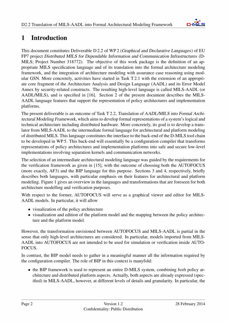
• At system level, we envisage a layered organization in two well-identified layers, namely thepolicy architecture layer and the D-MILS platform layer.
28 February 2014 Version 1.2Confidentiality: Public Distribution
Page 5
D2.2 Translation of MILS-AADL into Formal Architectural Modeling Framework
• The policy architecture layer consists of a interconnected set of MILS-AADL components ofcategory process (subject) or system.• The D-MILS platform layer consists of a set of MILS-AADL node components intercon-
nected through MILS-AADL bus components. The former are abstract representations ofD-MILS platform nodes, that is, machines with separation kernels deployed on them. Theycan be further decomposed into processor (which refer to single cores) and memory com-ponents. Components of category bus are abstractions of TTE switches.• The connections between the policy architecture and the D-MILS platform are expressed
through deployment links. These links can either be provided by the system designer (i.e,running on annotations) or left in charge of the configuration compiler.
Node X
Node Y
Node Z
Bus
Bus
DSubject
ASubject Subject
B CSubject
policyarchitecture
D-MILSplatform
deployment
Figure 2: Generic architecture of D-MILS system representation using MILS-AADL
An overall illustration of the proposed architecture for the representation of D-MILS systems usingMILS-AADL language concepts is provided in Figure 2. The equivalent textual representation usingMILS-AADL is as follows:
system implementation a_dmils_system.impl
-- 1st layer: the policy architecture
-- described as an interconnected set of ’subjects’ or ’systems’,-- each one corresponding to the ’boxes’ in the policy architecture-- and, optionally, their deployment on platform processors
Page 6 Version 1.2Confidentiality: Public Distribution
28 February 2014

D2.2 Translation of MILS-AADL into Formal Architectural Modeling Framework
subcomponentsA : subject Subject-A-Type [ running on X ]B : subject ... [ running on Y ]C : subject ... [ running on Y ]D : subject ... [ running on Z ]...
-- eventually, all the (functional) flow connections-- between the subjects...
flows...
-- 2nd layer: the D-MILS platform
-- describes the platform using HW elements restricted to-- ’node’ for D-MILS platform nodes-- ’bus’ for the TTE Switches-- ’access’ bindings for the communication links
subcomponentsX: node Machine1-Type accesses SW1Y: node ... accesses SW2Z: node ... accesses SW1SW1: bus TTE1-Type accesses SW2SW2: bus ......
end a_dmils_system.impl;
28 February 2014 Version 1.2Confidentiality: Public Distribution
Page 7

D2.2 Translation of MILS-AADL into Formal Architectural Modeling Framework
3 High-Level Representation using AUTOFOCUS
We propose to use the AUTOFOCUS 3 tool to represent a high-level view of the application, theplatform and their mapping in a D-MILS model. In particular, AUTOFOCUS combines a logicalarchitecture – that represents a policy architecture – with a platform model, by deploying the logicalarchitecture onto the platform model. The tool allows visualization of the security policy, the plat-form model and the deployment information contained in a MILS-AADL model. Furthermore, theplatform model and the deployment can be edited.
3.1 Autofocus Overview
AUTOFOCUS allows component-based modeling of reactive, distributed systems and provides val-idation and verification mechanisms for these models. The modeling language is based on precisesemantics from the FOCUS theory. A comprehensive introduction to the semantics can be foundin [10].
In AUTOFOCUS the system consists of a set of communicating components, each having its ownbehavior specification. Each component has a defined interface (i.e., its black-box view) and animplementation (i.e., its white-box behavior). The interface consists of a set of input and outputports, and connections are always directed from an output port to an input port.
The components describe the system from the logical point of view; there is no restriction on theunderlying technical platform in terms of electronic control units, memory or communication buses.AUTOFOCUS provides an additional technical layer to describe the technical platform consisting ofelectronic control units, communication buses and hardware ports, which describe the connection tosensors and actuators.
Having described the logical architecture and the execution environment, these two views of thesystem must be related to each other. In particular, each logical component has to be mapped ontosome execution resource. Furthermore, logical signals need to be mapped to hardware ports, e.g. I/Odevices or bus messages.
AUTOFOCUS is implemented by the AUTOFOCUS 3 Tool (AF3) - an open source software whichcan be downloaded under http://af3.fortiss.org/. The tool was developed to support aseamless model-based engineering of software for embedded devices. AF3 supports requirements,formal specification of structure and behavior of a logical architecture based on components, inte-grated testing and verification as well as the description of specific technical platforms and the de-ployment of logical components to the technical platform. A user friendly graphical interface allowsintuitive modeling, simulation and analysis of the system.
3.2 D-MILS System Representation in AUTOFOCUS
The AUTOFOCUS description of a D-MILS model focuses on defining how the different subjectsare deployed on the platform. It includes a logical architecture of the application software, that weinterpret as a policy architecture. A model of the platform is also included, defining the hardware
Page 8 Version 1.2Confidentiality: Public Distribution
28 February 2014

D2.2 Translation of MILS-AADL into Formal Architectural Modeling Framework
setting of the system. Finally, the AUTOFOCUS representation defines a (possibly partial) mappingof the subjects onto machines of the platform. The logical architecture, the platform model and thedeployment correspond to subparts of a global AUTOFOCUS model. Application and platform aredefined independently, and then bound through the deployment. The policy architecture is defined bythe application software model, therefore changing it at this level of abstraction is not possible. How-ever, the representations of the platform and the deployment can be edited using the AUTOFOCUS 3tool.
Figure 3: An example of logical architecture in AUTOFOCUS.
The logical architecture of the application is represented by a set of AUTOFOCUS components,with connections between them. An example is given in Figure 3. Each box is an AUTOFOCUScomponent, interpreted as a security domain1, as implicitly defined in the policy architecture layer ofthe MILS-AADL system model. A connection between components indicates that information maybe transmitted according to the direction of the connection. The connections define the intransitivepolicy architecture to be established and enforced by the configuration of the platform.
Figure 4: A D-MILS platform model in AUTOFOCUS.
1The term security domain introduced here is an abstract concept that is not equivalent to other modeling terms usedhere. For the purpose of this security analysis it is convenient in this example to interpret each component as a distinctsecurity domain. In another context a security domain may be interpreted to be a collection of components. This exampleis further described in Section 5.3.
28 February 2014 Version 1.2Confidentiality: Public Distribution
Page 9
D2.2 Translation of MILS-AADL into Formal Architectural Modeling Framework
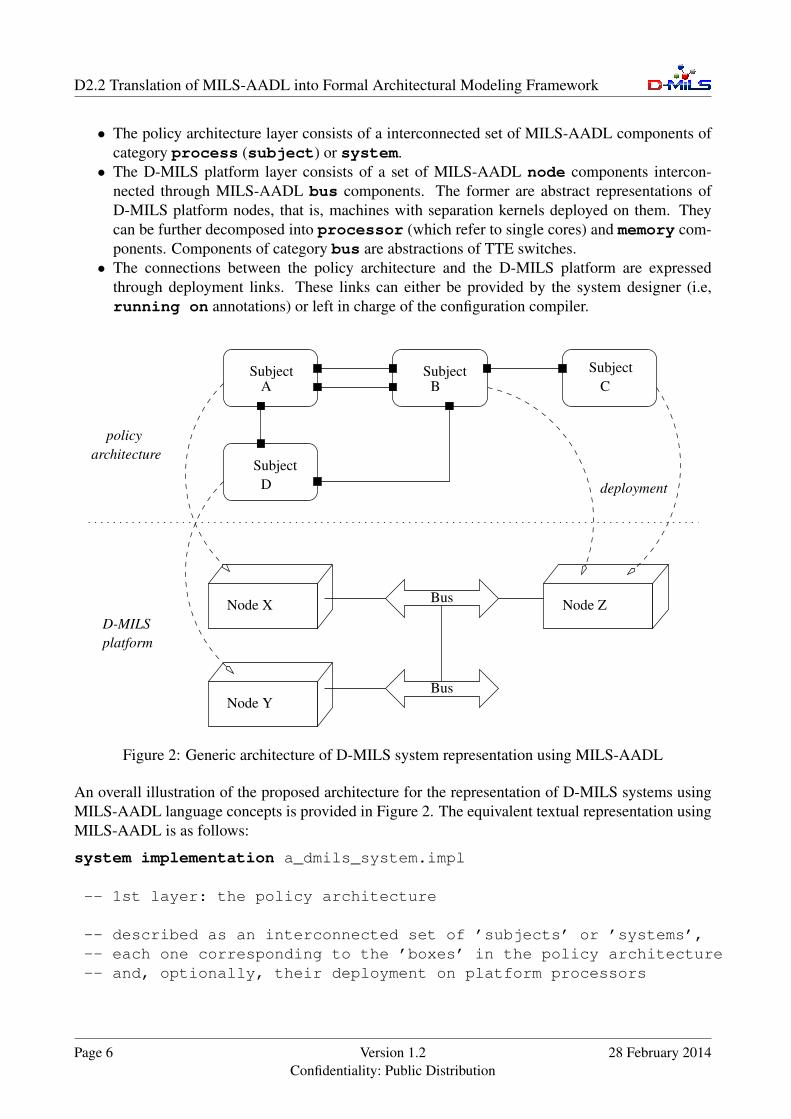
A platform model is represented by nodes and switches linked with wires, as depicted in Figure 4.Each node corresponds to a physical machine, possibly running a separation kernel. The wires indi-cate how switches and machines are physically connected. The AUTOFOCUS 3 tool allows the userto manipulate the platform model by adding, removing and binding elements.
Figure 5: Deployment editor in AUTOFOCUS.
Finally, the deployment is represented by assigning each subject of the policy architecture to a partic-ular machine of the platform. AUTOFOCUS 3 provides an editor to visualize and edit this mapping,depicted in Figure 5. On the figure, one sees that the selected machine, namely Machine3, hosts thesoftware components user and dispatch.
3.3 Extraction of MILS-AADL representation
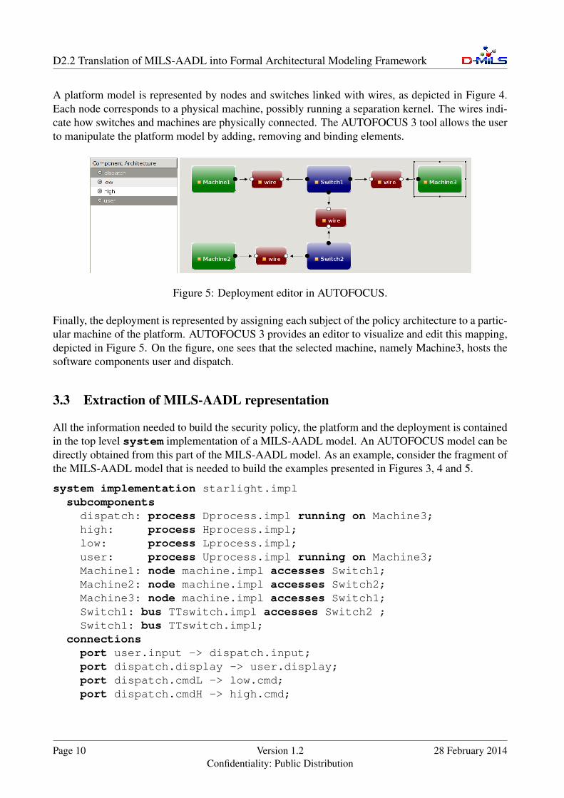
All the information needed to build the security policy, the platform and the deployment is containedin the top level system implementation of a MILS-AADL model. An AUTOFOCUS model can bedirectly obtained from this part of the MILS-AADL model. As an example, consider the fragment ofthe MILS-AADL model that is needed to build the examples presented in Figures 3, 4 and 5.
system implementation starlight.implsubcomponents
dispatch: process Dprocess.impl running on Machine3;high: process Hprocess.impl;low: process Lprocess.impl;user: process Uprocess.impl running on Machine3;Machine1: node machine.impl accesses Switch1;Machine2: node machine.impl accesses Switch2;Machine3: node machine.impl accesses Switch1;Switch1: bus TTswitch.impl accesses Switch2 ;Switch1: bus TTswitch.impl;
connectionsport user.input -> dispatch.input;port dispatch.display -> user.display;port dispatch.cmdL -> low.cmd;port dispatch.cmdH -> high.cmd;
Page 10 Version 1.2Confidentiality: Public Distribution
28 February 2014

D2.2 Translation of MILS-AADL into Formal Architectural Modeling Framework
port low.res -> high.resL;port high.res -> dispatch.res;
end starlight.impl;
In general, building each part (policy architecture, platform and deployment) of the AUTOFOCUSdescription of a MILS-AADL system model is done as follows.
• The policy architecture is obtained by:
1. Creating an AUTOFOCUS component for each process or system subcomponent.
2. For each port entry either in the connections or flows section, that binds a outputport from a source subject to an input port of a target subject, creating a connectionfrom the AUTOFOCUS component corresponding to the source suject to the componentcorresponding to the target subject.
• The platform model is obtained by:
1. Creating a processor element for each node subcomponent.
2. Creating a switch element for each bus subcomponent.
3. Creating a wire element for each accesses binding. This wire links the switch elementcorresponding to the bus given after accesses to the element corresponding to the busor node declared before accesses.
• The deployment information is obtained from the running on bindings in the declarationof process or system subcomponents. Whenever a process or system is declaredrunning on a node, the AUTOFOCUS component corresponding to the process orsystem is deployed on the processor created after the node.
28 February 2014 Version 1.2Confidentiality: Public Distribution
Page 11
D2.2 Translation of MILS-AADL into Formal Architectural Modeling Framework
4 The Intermediate Framework for Architecture Modeling
The selection of intermediate languages has to meet the requirements for the verification frameworkas identified in [15, Sect. 4+5]. These have been derived from the specific requirements of the twocase studies, the fortiss Smart Microgrid Demonstrator [13, Sect. 5] and the Frequentis Voice ServiceDemonstrator [14, Sect. 5].
In summary, the main challenge is to adapt or extend existing approaches for the verification of func-tional, safety and dependability, and security properties both at the level of the system architectureand of the single components. The required analysis are described in D-MILS Deliverable D 4.1 [19]while D-MILS Deliverable D 3.1 [17] identifies appropriate intermediate languages and supportingtools.
Another collection of requirements is imposed by the back-end of the D-MILS tool chain to bedeveloped in WP 5. This back-end will essentially be a configuration compiler that transforms MILS-AADL representations of policy architectures into low-level implementations involving separationkernels and communication networks [15, Sect. 7]. For this step, the BIP language [26] is envisagedas the intermediate formal language for architectural and platform modeling.
Note that BIP is not only employed as an intermediate language for architecture modeling but alsofor verification purposes. In [18, Sect. ??] we outline the essential principles of the correspondingtranslation of MILS-AADL to BIP, tailored to the verification tools to be implemented and used inWP 4. The latter are mainly oriented towards the analysis of the dynamic behavior of a system inexecution. The present deliverable, in comparison, shows the parts of the translation that are targetingthe D-MILS platform and its associated deployment information.
4.1 BIP Overview
BIP (Behavior, Interaction, Priority) [3] is a component framework intended to support rigorous sys-tem design [2]. BIP allows the construction of composite hierarchically structured components fromatomic components characterized by their behavior and their interface. Components are composed bylayered application of interactions and of priorities. Interactions express synchronization constraintsbetween actions of the composed components while priorities are used to select amongst possibleinteractions and to steer system evolution so as to meet performance requirements, e.g., to expressscheduling policies. Interactions are described in BIP as the combination of two types of protocols:rendez-vous to express strong symmetric synchronization and broadcast to express triggered asym-metric synchronization. The combination of interactions and priorities confers BIP expressivenessnot matched by any other existing formalism [6]. Further details on the BIP syntax and semanticscan be found in project deliverables D 3.1 [17] and D 3.2 [18].
BIP defines a clean and abstract concept of architecture separate from behavior. Architecture inBIP is a first class concept with well-defined semantics that can be analyzed and transformed. BIPrelies on rigorous operational semantics that has been implemented by three execution engines forcentralized, distributed and real-time execution. It is used as a unifying semantic model in a rigoroussystem design flow. Rigor is ensured by two kinds of tools: 1) D-Finder [4, 5], a verification tool forchecking safety properties and deadlock-freedom in particular; 2) source-to-source transformers [8],
Page 12 Version 1.2Confidentiality: Public Distribution
28 February 2014
D2.2 Translation of MILS-AADL into Formal Architectural Modeling Framework
that allow progressive refinement of the application to get a correct implementation. Further detailson the verification tools can be found in deliverable D 4.1 [19].
4.2 System-Level Modeling with BIP
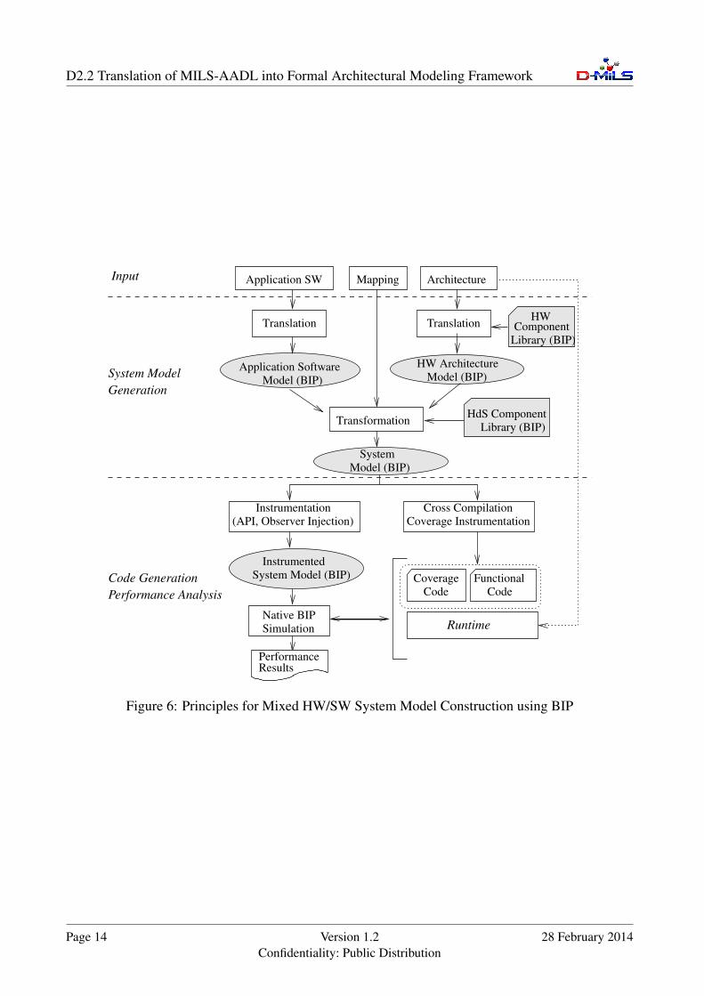
We briefly recall hereafter the principles for the construction of a mixed software/hardware systemmodel introduced in [9]. The flow of the construction is illustrated in Figure 6. The method takes asinputs representations of the application software, the hardware platform and the mapping. The out-put is the system model in BIP. The construction breaks down into several well identified translationand model transformation phases operating on the initial representations and BIP models.
In the current implementation, the representation of the various inputs is realized using the concreteformalism available in the DOL framework [25]. In the same spirit as AADL, the DOL frameworkprovides several languages for the representation of applications software, multi-processor architec-tures and their mappings. Concretely, application software is defined using a variant of the Kahn pro-cess network model. It consists of a set of deterministic, sequential processes (in C) communicatingasynchronously through FIFO channels. The hardware architecture is described as interconnectionsof computational and communication resources such as processors, buses and memories. The map-ping associates application software components to resources of the hardware architecture, that is,processes to processors and FIFO channels to memories. All architectural information is providedusing XML languages.
In principle, the system model embodies the hardware constraints into the software model accordingto the mapping. The construction of the system model in BIP is obtained by a sequence of translationsand transformations of the initial DOL representations, as follows:
1. automatic translation of the application software in DOL into a BIP model. The translation isstructural: processes and FIFO channels in DOL are translated into atomic components in BIP,connections in DOL are translated into connectors in BIP.
2. automatic translation of the hardware architecture model in DOL into a BIP model. The trans-lation is also structural: hardware resources (processor, memory, bus, etc) are translated intoBIP components, hardware interconnections are translated into connectors in BIP.
3. construction of an initial, abstract system model using source-to-source transformation of theprevious two models and composition according to the mapping.
4. finally, refinement of the previous system model by including specific timing information aboutthe execution of the software on the platform.
We previously ensured that all the transformations above preserve functional properties of the appli-cation software model. Moreover, the system model includes specific timing constraints for executionof the application software on the hardware platform. These constraints are obtained by cross com-piling the application model into executable code for the target and measuring the execution timeof the elementary blocks of code (e.g., BIP transitions). The timing information is integrated in thesystem model through the source-to-source transformation done in the last refinement step (item 4 inthe list above).
28 February 2014 Version 1.2Confidentiality: Public Distribution
Page 13
D2.2 Translation of MILS-AADL into Formal Architectural Modeling Framework
System Model (BIP)
Instrumented
Instrumentation
(API, Observer Injection)
TransformationHdS Component
Library (BIP)
HWComponent
Mapping Architecture
Cross Compilation
Coverage Instrumentation
Coverage
Code
Functional
Native BIP
Simulation
PerformanceResults
Translation
Application SW
System
Model (BIP)
Code
Library (BIP)
Runtime
Performance AnalysisCode Generation
GenerationSystem Model
Input
Model (BIP)Application Software
Model (BIP)HW Architecture
Translation
Figure 6: Principles for Mixed HW/SW System Model Construction using BIP
Page 14 Version 1.2Confidentiality: Public Distribution
28 February 2014

D2.2 Translation of MILS-AADL into Formal Architectural Modeling Framework
4.3 D-MILS Systems Modeling in BIP
D-MILS systems are represented in BIP as illustrated in Figure 7. This model corresponds to thegeneric MILS-AADL example presented earlier in Section 2. At top level, the model represents theplatform elements, that is, the interconnection of node (machine) and bus (switch) components.
Node components are essentially place-holders for the set of policy subjects deployed onto them.Their associated BIP models are obtained following the translation described in D-MILS Deliver-able D 3.2 [18]. In addition, the subject components are explicitly connected with communicationwrappers. The latter are used to break and wrap the direct interaction on event and/or data ports atthe policy architecture layer using primitives for network-based communication. Intuitively, outputevents and/or the changes on output data ports are wrapped as packets and sent over the network.
Bus components are an abstraction of the communication switches used within the network. Theyconsists of a collection of virtual link components, one for every communication flow ongoing on theswitch. The functionality of virtual link components is relatively straightforward. They are relayingcommunication packets received on the input port to the associated output ports. In the proposedmodel, virtual links operate in parallel and no global coordination is enforced. Nevertheless, specificscheduling can be considered e.g, if needed for validation of extra-functional properties at systemlevel.
BusModel
ModelBus
Subject A
Node X
Subject D
Node Y
Subject B Subject C
Node Z
(1) (1)
(2) (2)(3)
(3)
(3)
(4)
(4)
(4)
MILS-AADL Subject (Process or System)
HW Platform Component
HdS Communication Wrapper
Figure 7: Overall architecture of D-MILS system models in BIP
We should notice that the D-MILS system representation in BIP is structure-preserving. That is, allthe elements of the original D-MILS system expressed in MILS-AADL are present in the intermedi-ate representation. Moreover, all the MILS-AADL connections are also either preserved or refined.
Finally, let us remark that the proposed representation in BIP does not cover two important aspects,which can potentially occur in MILS-AADL. First, it abstracts away the potential complexity of nodecomponents. In MILS-AADL, nodes can represent arbitrarily complex machines, with many proces-sors and complex memory hierarchies. For the time being, this low-level decomposition is ignored.
28 February 2014 Version 1.2Confidentiality: Public Distribution
Page 15

D2.2 Translation of MILS-AADL into Formal Architectural Modeling Framework
It could be, however, taken into account by constructing a more refined model of nodes in BIP, whichreflects the physical organization. Second, the D-MILS systems considered are fully static, that is, attop level, no mode behavior can be defined. Therefore, both the policy architecture and the D-MILSplatform are fixed for the entire execution of the system. Nonetheless, mode behavior is allowedwithin every subject. Hence, if coordination between modes of several subjects is needed, it must berealized using explicit event or data-flow communication between them.
4.3.1 Buses and Virtual Links
The Bus components have a concrete representation in BIP. Each Bus component is a composition ofatomic virtual link components modeling the transmission of data packets corresponding to the samecommunication flow over the network.
The virtual link component illustrated in Figure 8, models the transfer of data over the bus, once itgets access to the bus, from the input port towards the output port. For the time being, this componentis untimed and models only the data transfer. If needed, this model can be further refined into a timedmodel that includes the (variable) transfer delay, based on the actual data size, the concrete QoScharacteristics of the bus (switch), etc. Moreover, additional scheduling constraints between virtuallinks can be expressed if needed at bus level either by using (dynamic) priorities or through insertionof explicit scheduler components for controlling explicitly the sending of different packets.
All these models are currently being developed as BIP hardware library.
recvpacket
sendpacket
sendrecv
recv
recv recv
recv
recv3
recv1 send send1
sendsend2
send3
send send
send4
recv2
recv4
Figure 8: BIP Models for Virtual Link and Bus Components
4.3.2 Event/Data Ports Communication Wrapper
Communication wrapper components are needed to mediate between operational components (withinthe policy layer) and communication network components (within the platform layer). Their role isto intercept the triggering of event ports and/or the changes of data ports and to wrap them as packetsto be transitted on the D-MILS network.
Page 16 Version 1.2Confidentiality: Public Distribution
28 February 2014

D2.2 Translation of MILS-AADL into Formal Architectural Modeling Framework
[x 6= x0]
sendpacket
packet:= marshall(x)x0 := x
in-xx
recvpacket x
out-x
recv out-xsendin-x[x = x0]
in-xout-xx x
x:= unmarshall(packet)
Figure 9: BIP Models for wrappers for input/output data ports
Figure 9 presents a model for the communication wrapper for input/output data ports. On the outputside (left side of Figure 9), the component interacts with the output port in order to detect changes ofthe associated data. When a change is detected, the value of the data port is encapsulated within anetwork packet and delivered to the network. On the input side (right side of Figure 9), the behavioris dual: whenever a packet is received, the associated data is extracted from it and used to trigger theassociated input data port in the functional component. The wrapping of event ports can be done in asimilar manner.
Alternatively, more or less sophisticated wrapping mechanisms can be developed. The approach pre-sented above is entirely data-driven by the output (transmitting) side. Alternative solutions could be,for example, time-driven models where the packets are periodically generated regardless the actualchange of the data port. Or, data-driven by the input side, where the exchange of network packets isinitiated on-demand by the input (receiving) component. All these mechanisms are developed as BIPcomponents within the hardware dependent software communication library. The choice amongstthem belong to the system designer.
4.4 Translation from MILS-AADL
The construction of D-MILS system models follows the general principles identified for the rigorousdesign flow using BIP systems:
• translation of the policy architecture layer using BIP. This translation has been described inthe Deliverable D 3.2 [18]. It covers all the functional aspects of the subjects such as modebehavior, data and event flow communication, etc.• representation of the D-MILS platform layer using BIP. This step uses a specific component
library in BIP for describing hardware elements. In particular, this library contains the compo-nents needed for the modeling of network switches.• the combination of the two above BIP models towards a single system model in BIP. The
policy architecture and the platform models in BIP are wired together according to deployment
28 February 2014 Version 1.2Confidentiality: Public Distribution
Page 17

D2.2 Translation of MILS-AADL into Formal Architectural Modeling Framework
constraints. This operation requires several steps in order to handle communication over thenetwork, that is:
- break atomic interactions between components deployed on different processors and in-sert the appropriate communication wrappers components. These components are devel-oped beforehand as part of a hardware-specific-software (HdS) component library.
- replace the direct communication between wrappers by a (route) composition of virtuallinks components. One virtual link component is needed for every network switch usedto deploy that communication.
The different translation/transformation phases and the additional BIP component libraries (HW,HdS) are currently being developed.
The translation/transformation from MILS-AADL to BIP is built on the existing infrastructure forparsing and construction of XML abstract syntax trees corresponding to MILS-AADL specifications.The overall architecture is depicted in Figure 10.
MILS-AADL
BIP
platformmodel
policymodel
XML
BIP
MILS-AADL
translation translation
transformation
systemmodel BIP
AutoFocus
BIP
HW Lib
BIP
HdS Lib
Figure 10: The MILS-AADL to BIP translator
Page 18 Version 1.2Confidentiality: Public Distribution
28 February 2014

D2.2 Translation of MILS-AADL into Formal Architectural Modeling Framework
5 D-MILS System Examples
In the following, we present three complete MILS-AADL system examples that demonstrate the useof MILS-AADL language features for policy architecture and platform modeling.
5.1 Platform components
In the next examples, we model MILS platform using a library of components providing high-levelmodels for the hardware components. These components are simply defined by their types, i.e.node for a D-MILS node (machine) and bus for a switch. They could be more detailed, i.e. a nodedescription could state its number of processors and memory size. We assume that the followingfragment of MILS-AADL is included in each of the next examples.
-------------------------------------------------------------------- MILS platform components------------------------------------------------------------------
node machineend machine;node implementation machine.implend machine.impl;
bus TTswitchend TTswitch;bus implementation TTswitch.implend TTswitch.impl;
5.2 Home Gateway
The following MILS-AADL model of a home gateway system is inspired by a real application, takenfrom [11]. The system collects information about the temperature and the presence of people ina building, then analyses them and takes decisions to decrease or increase the temperature valueaccording to the presence value.
The associated security property is that the presence of people in the building is considered secret.Thus, an intruder observing the public temperature variation should not be able to deduce the presencevalue.
The platform consists of two machines directly connected by a cable. The presence detector and thecomponent in charge of analysis are both deployed on the same machine.
-------------------------------------------------------------------- MILS-AADL Model of Home Gateway System [CLB08]------------------------------------------------------------------
28 February 2014 Version 1.2Confidentiality: Public Distribution
Page 19

D2.2 Translation of MILS-AADL into Formal Architectural Modeling Framework
constants-- temperature recommended when nobody is in the building
theta1: real := 15.0;-- temperature recommended when a person is in the building
theta2: real := 25.0;-- time limit for the analyse process
timeout: int := 2 ;
---- HomeGateway System--system HomeGateway
featuressin: in event port;sout: in event port;
end HomeGateway;system implementation HomeGateway.imp
subcomponentstemp : process TempDevice.imp running on Machine1;pres : process PresSensor.imp running on Machine2;analyse : process Analyse.imp running on Machine2;Machine1 : node machine.impl accesses Machine2;Machine2 : node machine.impl accesses Machine1;
connectionsport sin -> pres.inP;port sout-> pres.outP;
flowsport temp.outT -> analyse.inT;port pres.P -> analyse.P;port analyse.deltaT-> temp.deltaT;
end HomeGateway.imp
---- Temperature component sends the temperature value to the-- analyse and then regulate it.--process TempDevice
features-- temperature value to rectifydeltaT : in data port real;-- collected temperature valueoutT: out data port real;
end TempDevice;process implementation TempDevice.imp
Page 20 Version 1.2Confidentiality: Public Distribution
28 February 2014

D2.2 Translation of MILS-AADL into Formal Architectural Modeling Framework
subcomponentsT: data continuous default 17.0;
modesoff: initial mode while T’ = -0.1;onn: mode while T’ = 0.02 and T <= theta2;
transitionsonn-[outT:=T]-> onn;off-[outT:=T]-> off;off-[when deltaT<0]-> onn;onn-[when deltaT>0]-> off;
end TempDevice.imp
---- presence component sends the presence value to the analyse--process PresSensor
featuresinP: in event port;outP: in event port;P: out data port bool default false;
end PresSensor;process implementation PresSensor.imp
modesabsence: initial mode;presence: mode;
transitionsabsence-[when inP then P:= true] -> presence;presence-[when outP then P:=false] -> absence;
end PresSensor.imp
----Analyse component compare collected information and take decisions--process Analyse
featuresP: in data port bool;inT: in data port real;deltaT:out data port real;
end Analyse;process implementation Analyse.imp
subcomponentstimer: data clock;
modesidle: initial mode;
28 February 2014 Version 1.2Confidentiality: Public Distribution
Page 21

D2.2 Translation of MILS-AADL into Formal Architectural Modeling Framework
wait: mode;treat: mode while timer <= timeout min;
transitionsidle -[then timer := 0]-> treat;treat-[when [P=false and inT>theta2 ] then
deltaT:= inT-theta2] -> wait;treat-[when [P=true and inT<theta1 ] then
deltaT:= inT-theta1] -> wait;wait -[when timer >= timeout min]-> idle;
end Analyse.imp
Page 22 Version 1.2Confidentiality: Public Distribution
28 February 2014

D2.2 Translation of MILS-AADL into Formal Architectural Modeling Framework
5.3 Starlight Interactive Link
The next MILS-AADL model is inspired by the Starlight example proposed in [12]. It is used to showusefulness of expressing security policies trough architectures with filters. The example actuallycomes from a project of the Australian Defence Force, and is more detailed in [1]. It assumes foursecurity domains, namely low, a low-security network, high, a high-security network, user, auser, and dispatch, the interface between the user and the networks. Note that here, the securitydomains match the subcomponents of the toplevel system component. We assume that the user cansend commands to each of the networks and will receive a corresponding result. Results computed bythe low-security network are transmitted to the user through the high-security network. A dedicatedinput from the user toggles between the high-security and the low-security mode. In the originalexample, user input is provided by keyboard and mouse, and output is displayed through graphicalinterfaces (Xserver).
The associated security property is that the low-security network should receive only commands thatare input in low security mode and should gain no knowledge of the commands input in high-securitymode nor of their results. In [12], this property is formally stated through the policy architecturedepicted in Figure 11 where f is a filter specifying that only command input in low mode is allowedto pass.
high
low
dispatch
f
user
Figure 11: Policy architecture for the “Starlight” example.
This examples define the security policy from Figure 11, without the filter function. It also defines aplatform consisting of three machines connected with two switches.
Here we take the following modeling decisions:
• Each network is modeled by a single process.• Commands and results are represented by integer values where the result of a command is its
square.
-------------------------------------------------------------------- MILS-AADL Model of Starlight Interactive Link [CM12]------------------------------------------------------------------
-- The number 0 is the command for toggling between high and low-- security.constants
toggle: int: 0;
------------------------------------------------------------------
28 February 2014 Version 1.2Confidentiality: Public Distribution
Page 23

D2.2 Translation of MILS-AADL into Formal Architectural Modeling Framework
-- Processes------------------------------------------------------------------
-- Dprocess : dispatch between high and low security networksprocess Dprocess
featuresinput: in event data port int;display: out event data port int;cmdH: out event data port int;cmdL: out event data port int;res: in event data port int;
end Dprocess;process implementation Dprocess.impl
subcomponentsi: data int; -- storing the last input from the userr: data int; -- storing the next result for the user
modesH: initial mode; -- high sec mode, waitingHr: mode; -- received result to displayHc: mode; -- received user inputL: mode; -- idem with low sec modeLr: mode;Lc: mode;
transitionsH -[input(i)] -> Hc;Hc -[cmdH(i) when i != toggle] -> H; -- treat inputHc -[when i = toggle] -> L;H -[res(r)] -> Hr; -- received result, displayHr -[display(r)] -> H;-- The same construction for L follows.L -[input(i)] -> Lc;Lc -[cmdL(i) when i != toggle] -> L;Lc -[when i = toggle] -> H;L -[res(r)] -> Lr;Lr -[display(r)] -> L;
end Dprocess.impl;
process Hprocessfeatures
cmd: in event data port int;resL: in event data port int;res: out event data port int;
end Hprocess;process implementation Hprocess.impl
Page 24 Version 1.2Confidentiality: Public Distribution
28 February 2014
D2.2 Translation of MILS-AADL into Formal Architectural Modeling Framework
subcomponentsi: data int;r: data int;
modeswaiting: initial mode;computing: mode;
transitionswaiting -[cmd(i) then r := i*i] -> computing;waiting -[resL(r)] -> computing ;computing -[res(r)] -> waiting ;
end Hprocess.impl;
process Lprocessfeatures
cmd: in event data port int;res: out event data port int;
end Lprocess;process implementation Lprocess.impl
subcomponentsi: data intr: data int
modeswaiting: initial mode;computing: mode;
transitionswaiting -[cmd(i) then r := i*i] -> computing;computing -[res(r)] -> waiting;
end Lprocess.impl;
process Uprocessfeatures
display: in event data port int;input: out event data port int;
end Uprocess;process implementation Uprocess.impl
subcomponentsi: data int default 1;r: data int;
modeswaiting: initial mode;
transitionswaiting -[input(i) then i := random(10)] -> waiting;waiting -[display(r)] -> waiting ;
end Uproc.impl;
28 February 2014 Version 1.2Confidentiality: Public Distribution
Page 25

D2.2 Translation of MILS-AADL into Formal Architectural Modeling Framework
-------------------------------------------------------------------- Overall system------------------------------------------------------------------
system starlightend starlight;system implementation starlight.impl
subcomponentsdispatch: process Dprocess.impl running on Machine3;high: process Hprocess.impl;low: process Lprocess.impl;user: process Uprocess.impl running on Machine3;Machine1: node machine.impl accesses Switch1;Machine2: node machine.impl accesses Switch2;Machine3: node machine.impl accesses Switch1;Switch1: bus TTswitch.impl accesses Switch2 ;Switch2: bus TTswitch.impl;
connectionsport user.input -> dispatch.input;port dispatch.display -> user.display;port dispatch.cmdL -> low.cmd;port dispatch.cmdH -> high.cmd;port low.res -> high.resL;port high.res -> dispatch.res;
end starlight.impl;
Page 26 Version 1.2Confidentiality: Public Distribution
28 February 2014

D2.2 Translation of MILS-AADL into Formal Architectural Modeling Framework
5.4 Cryptographic Controller
Finally, the following listing demonstrates the use of subcomponent declarations, data flows andencryption keys for specifying a simple cryptographic controller, essentially taken from [7]. Hereinformation flows from a red (secure) network to a black (insecure) one, and where the payload isencrypted before using the public key mykey.
The platform consists of two machines directly connected. The Machine1 hosts all sensitive com-ponents, whereas the Machine2 is connected to the insecure network.
---- Crypto controller example---- Properties to be verified:-- outgoing header is identical to incoming header:-- fst(root.outframe) = fst(root.inframe)-- outgoing payload is encryption of incoming payload:-- snd(root.outframe) = encrypt(snd(root.inframe), mykey)--constants
Frame: type := (Header, Payload);Header: type := int;Payload: type := int;MyKeys: asymmetric key pair;
---- Overall system with four components connected by channels--system CryptoController
featuresinframe: in data port Frame;outframe: out data port Frame;
end CryptoController;system implementation CryptoController.Imp
subcomponentsred: process Splitter.Imp running on Machine1;bypass: process Bypass.Imp running on Machine1;crypto: process Crypto.Imp running on Machine1;black: process Merger.Imp running on Machine2;Machine1: node machine.impl accesses Machine2;Machine2: node machine.impl accesses Machine1;
flowsport inframe -> red.frame;port red.header -> bypass.inheader;port red.payload -> crypto.inpayload;port bypass.outheader -> black.header;
28 February 2014 Version 1.2Confidentiality: Public Distribution
Page 27

D2.2 Translation of MILS-AADL into Formal Architectural Modeling Framework
port crypto.outpayload -> black.payload;port black.frame -> outframe;
end CryptoController.Imp;
---- Splitter component for decomposing frames into header and payload--process Splitter
featuresframe: in data port Frame;header: out data port Header;payload: out data port Payload;
end Splitter;process implementation Splitter.Imp
flowsport fst(frame) -> header;port snd(frame) -> payload;
end Splitter.Imp;
---- Bypass component for forwarding header--process Bypass
featuresinheader: in data port Header;outheader: out data port Header;
end Bypass;process implementation Bypass.Imp
flowsport inheader -> outheader;
end Bypass.Imp;
---- Crypto component for encrypting payload--process Crypto
featuresinpayload: in data port Payload;outpayload: out data port Payload;
end Crypto;process implementation Crypto.Imp
constantsmykey: public key default pub(MyKeys);
flows
Page 28 Version 1.2Confidentiality: Public Distribution
28 February 2014

D2.2 Translation of MILS-AADL into Formal Architectural Modeling Framework
port encrypt(inpayload, mykey) -> outpayload;end Crypto.Imp;
---- Merger component for re-assembling frames from header and payload--process Merger
featuresheader: in data port Header;payload: in data port Payload;frame: out data port Frame;
end Merger;process implementation Merger.Imp
flowsport (header, payload) -> frame;
end Merger.Imp;
network CryptoNetend CryptoNet;network implementation CryptoNet.Impend CryptoNet.Imp;
28 February 2014 Version 1.2Confidentiality: Public Distribution
Page 29
D2.2 Translation of MILS-AADL into Formal Architectural Modeling Framework
References
[1] M. Anderson, C. North, J. Griffin, R. Milner, J. Yesberg, and K. Yiu. Starlight: Interactive link.In 12th Annual Computer Security Applications Conference, pages 55–63, 1996.
[2] A. Basu, S. Bensalem, M. Bozga, J. Combaz, M. Jaber, T.-H. Nguyen, and J. Sifakis. RigorousComponent-Based System Design Using the BIP Framework. IEEE Software, 28(3):41–48,2011.
[3] A. Basu, M. Bozga, and J. Sifakis. Modeling Heterogeneous Real-time Systems in BIP. InSoftware Engineering and Formal Methods SEFM’06 Proceedings, pages 3–12. IEEE Com-puter Society Press, 2006.
[4] S. Bensalem, M. Bozga, T-H. Nguyen, and J. Sifakis. D-Finder: A tool for compositionaldeadlock detection and verification. In Proceedings of the 21st International Conference onComputer Aided Verification, pages 614–619, Berlin, Heidelberg, 2009. Springer-Verlag.
[5] Saddek Bensalem, Marius Bozga, Thanh-Hung Nguyen, and Joseph Sifakis. Compositionalverification for component-based systems and application. In Proceedings of the 6th Interna-tional Symposium on Automated Technology for Verification and Analysis, pages 64–79, Berlin,Heidelberg, 2008. Springer-Verlag.
[6] Simon Bliudze and Joseph Sifakis. A notion of glue expressiveness for component-based sys-tems. In CONCUR 2008 - Concurrency Theory, 19th International Conference, volume 5201of Lecture Notes in Computer Science, pages 508–522. Springer, 2008.
[7] Carolyn Boettcher, Rance DeLong, John Rushby, and Wilmar Sifre. The MILS Component In-tegration Approach to Secure Information Sharing. In 27thAIAA/IEEE Digital Avionics SystemsConference, St. Paul, MN, October 2008.
[8] Borzoo Bonakdarpour, Marius Bozga, Mohamad Jaber, Jean Quilbeuf, and Joseph Sifakis. Aframework for automated distributed implementation of component-based models. DistributedComputing, 25(5):383–409, 2012.
[9] Paraskevas Bourgos, Ananda Basu, Marius Bozga, Saddek Bensalem, Joseph Sifakis, and KaiHuang. Rigorous system level modeling and analysis of mixed hw/sw systems. In SatnamSingh, Barbara Jobstmann, Michael Kishinevsky, and Jens Brandt, editors, 9th IEEE/ACM In-ternational Conference on Formal Methods and Models for Codesign, MEMOCODE 2011,Cambridge, UK, 11-13 July, 2011, pages 11–20. IEEE, 2011.
[10] M. Broy and K. Stoelen. Specification and development of interactive systems: Focus onstreams, interfaces, and refinement, 2001.
[11] S. Chollet, P. Lalanda, and A. Bottaro. Transparently adding security properties to serviceorchestration. In 22nd Int. Conf. on Advanced Information Networking and Applications(AINAW 2008), pages 1363–1368, 2008.
Page 30 Version 1.2Confidentiality: Public Distribution
28 February 2014
D2.2 Translation of MILS-AADL into Formal Architectural Modeling Framework
[12] S. Chong and R. van der Meyden. Using architecture to reason about information security. InLayered Assurance Workshop, pages 1–11, 2012.
[13] Safety and security requirements for fortiss Smart Microgrid demonstrator. Technical ReportD1.1, Version 1.1, D-MILS Project, January 2013.
[14] Safety and security requirements for Frequentis Voice Service demonstrator. Technical ReportD1.2, Version 1.1, D-MILS Project, January 2013.
[15] Requirements for distributed MILS technology (draft). Technical Report D1.3, Version 0.1,D-MILS Project, April 2013.
[16] Specification of AADL/MILS. Technical Report D2.1, Version 1.2, D-MILS Project, May 2013.
[17] Review of the state of the art and candidate languages for intermediate representations. Tech-nical Report D3.1, Version 1.0, D-MILS Project, April 2013.
[18] Intermediate languages and semantics transformations for distributed mils – part 1. TechnicalReport D3.2, Version 1.0, D-MILS Project, October 2013.
[19] Analysis of state of the art in compositional reasoning for functional, safety and security formalverification. Technical Report D4.1, Version 0.1, D-MILS Project, May 2013.
[20] Peter H. Feiler and David P. Gluch. Model-Based Engineering with AADL: An Introductionto the SAE Architecture Analysis and Design Language. SEI Series in Software Engineering.Addison-Wesley, 2012.
[21] Peter H. Feiler and Ana Rugina. Dependability modeling with the Architecture Analysis & De-sign Language (AADL). Technical Note CMU/SEI-2007-TN-043, CMU Software EngineeringInstitute, 2007.
[22] John Rushby. A formal model for MILS integration. Project report, Computer Science Labora-tory, SRI International, Menlo Park, CA, May 2008.
[23] Architecture Analysis & Design Language (AADL) (rev. B). SAE Standard AS5506B, Interna-tional Society of Automotive Engineers, September 2012.
[24] Architecture Analysis and Design Language Annex (AADL), Volume 1, Annex E: Error ModelAnnex. SAE Standard AS5506/1, International Society of Automotive Engineers, June 2006.
[25] Lothar Thiele, Iuliana Bacivarov, Wolfgang Haid, and Kai Huang. Mapping applications to tiledmultiprocessor embedded systems. In Twan Basten, Gabriel Juhás, and Sandeep K. Shukla,editors, Seventh International Conference on Application of Concurrency to System Design(ACSD 2007), 10-13 July 2007, Bratislava, Slovak Republic, pages 29–40. IEEE ComputerSociety, 2007.
[26] Verimag/BIP. http://www.bip-components.com, 2012.
28 February 2014 Version 1.2Confidentiality: Public Distribution
Page 31