D2.2: Specification of FUTEBOL showcases · FUTEBOL research facilities for use of partners and...
46
D2.2: Specification of FUTEBOL showcases Revision: v.1.0 Work package WP 2 Task Task 2.2 and task 2.3 Due date 28/02/2017 Submission date 28/02/2017 Editor UFC Version 1.0 Authors Paulo Marques (IT), Valerio Frascolla (INTEL), Carlos Silva (UFC), Emanuel Dário (UFC), Raphael Braga (UFC), Alexandre Albano (UFC), João Pinheiro (UFC), Rodrigo Cavalcanti (UFC), André Almeida (UFC), Edmundo Madeira (UNICAMP), Leandro Villas (UNICAMP), Luiz Bittencourt (UNICAMP), Nelson Fonseca (UNICAMP), Allan Souza (UNICAMP), Marcelo Marotta (UFRGS), Henrique Resende (UFRGS), Juliano Wickboldt (UFRGS), Ariel Dalla-Costa (UFRGS), Matias Schimuneck (UFRGS), João Camargo (UFRGS), Moisés Ribeiro (UFES), Ricardo Mello (UFES), Rodolfo Villaça (UFES), Magnos Martinello (UFES), Alexandre Carmo (UFES), Felippe Mendonça (UFES), Rodolfo Picoreti (UFES), Cristina Dominicini (UFES), Rodolfo Valentim (UFES), Rafael Guimarães (UFES), Pedro Hasse (UFES), Víctor Martínez (UFES), Lucas Henrique (UFES), Pekka Aho (VTT), Martin Varela (VTT), Daniel F. Macedo (UFMG), Aloizio P. da Silva (UFMG) ,Johann M. Marquez-Barja (TCD), Pedro Alvarez (TCD), Luiz DaSilva (TCD), Ali Hammad (UNIVBRIS) Reviewers Valerio Frascolla (INTEL) Ali Hammad (UNIVBRIS), Johann M. Marquez-Barja (TCD), Marco Ruffini (TCD), Luiz DaSilva (TCD) Abstract This deliverable contains the description of the experiments (or showcases) considered for the FUTEBOL project, focusing on the wireless/optical convergence. Keywords Experiments, showcases, wireless/optical convergence This project has received funding from the European Union's Horizon 2020 for research, technological development, and demonstration under grant agreement no. 688941 (FUTEBOL), as well from the Digital Information and Communication Research and Development Science Center (CTIC), Brazil.
Transcript of D2.2: Specification of FUTEBOL showcases · FUTEBOL research facilities for use of partners and...

D2.2: Specification of FUTEBOL showcases
Revision: v.1.0
Work package WP 2 Task Task 2.2 and task 2.3 Due date 28/02/2017 Submission date 28/02/2017 Editor UFC Version 1.0 Authors Paulo Marques (IT), Valerio Frascolla (INTEL), Carlos Silva
(UFC), Emanuel Dário (UFC), Raphael Braga (UFC), Alexandre Albano (UFC), João Pinheiro (UFC), Rodrigo Cavalcanti (UFC), André Almeida (UFC), Edmundo Madeira (UNICAMP), Leandro Villas (UNICAMP), Luiz Bittencourt (UNICAMP), Nelson Fonseca (UNICAMP), Allan Souza (UNICAMP), Marcelo Marotta (UFRGS), Henrique Resende (UFRGS), Juliano Wickboldt (UFRGS), Ariel Dalla-Costa (UFRGS), Matias Schimuneck (UFRGS), João Camargo (UFRGS), Moisés Ribeiro (UFES), Ricardo Mello (UFES), Rodolfo Villaça (UFES), Magnos Martinello (UFES), Alexandre Carmo (UFES), Felippe Mendonça (UFES), Rodolfo Picoreti (UFES), Cristina Dominicini (UFES), Rodolfo Valentim (UFES), Rafael Guimarães (UFES), Pedro Hasse (UFES), Víctor Martínez (UFES), Lucas Henrique (UFES), Pekka Aho (VTT), Martin Varela (VTT), Daniel F. Macedo (UFMG), Aloizio P. da Silva (UFMG) ,Johann M. Marquez-Barja (TCD), Pedro Alvarez (TCD), Luiz DaSilva (TCD), Ali Hammad (UNIVBRIS)
Reviewers Valerio Frascolla (INTEL) Ali Hammad (UNIVBRIS), Johann M. Marquez-Barja (TCD), Marco Ruffini (TCD), Luiz DaSilva (TCD)
Abstract This deliverable contains the description of the experiments (or
showcases) considered for the FUTEBOL project, focusing on the wireless/optical convergence.
Keywords Experiments, showcases, wireless/optical convergence
This project has received funding from the European Union's Horizon 2020 for research, technological development, and demonstration under grant agreement no. 688941 (FUTEBOL), as well from the Digital Information and Communication Research and Development Science Center (CTIC), Brazil.
FUTEBOL – H2020 688941
D2.2: Specification of FUTEBOL showcases
© FUTEBOL Consortium 2016-2019 Page 2 of 46
Document Revision History
Version Date Description of change List of contributor(s)
v.0.1 13/12/2016 First ToC and some initial content that was not included in D2.1
IT
v.0.2 20/12/2016 Online version for partners’ contributions
UFC
v.0.3 17/02/2017 Draft version for internal review UFC
v.0.4 23/02/2017 Document sent to partners for their last inputs, addressing the raised comments
UFC
v.0.5 24/02/2017 Inclusion of the revision for experiment 1
IT/VTT/UFC
v.0.6 24/02/2017 Inclusion of the revision for experiment 2.2
UFES/UFC
v.0.7 27/02/2017 Inclusion of the revision for experiment 2.1
TCD/UFC
v.0.8 28/02/2017 Inclusion of the revision for experiment 3.1
UFRGS/UFC
v.1.0 28/02/2017 Version submitted to EC and RNP (Quality assurance checked)
TCD
Copyright notice
© 2016 - 2019 FUTEBOL Consortium
*R: report, P: prototype, D: demonstrator, O: other
Project co-funded by the European Commission in the H2020 Programme
Nature of the deliverable: to specify R, P, D, O* Dissemination Level
PU Public ü PP Restricted to other programme participants (including the Commission Services) RE Restricted to bodies determined by the FUTEBOL project CO Confidential to FUTEBOL project and Commission Services
FUTEBOL – H2020 688941
D2.2: Specification of FUTEBOL showcases
© FUTEBOL Consortium 2016-2019 Page 3 of 46
EXECUTIVE SUMMARY
Deliverable D2.2 – “Specification of FUTEBOL showcases” is a follow up of deliverable D2.1 – “Specification of FUTEBOL use cases, requirements, and architecture definition”. While in D2.1 the main focus was on the use cases, herein we focus on detailing each of the experiments (or showcases) within the use cases. Moreover, these experiments will further be implemented in the technical work package WP5 (and also impact WP3 and WP4).
As such, experiments address concrete research issues in the convergence wireless/optical networks utilizing the FUTEBOL research facilities, showcasing the potential of the project as a whole for prototyping and experimentation.
The experiments considered for FUTEBOL and described in this deliverable address a range of issues that span wireless and optical networks. Those issues include: spectrum sharing following the LSA paradigm, network management and real-time robots control using the SDN approach, and monitoring/processing data from IoT devices.
For each experiment anticipated in the project, this deliverable describes: the objectives of the experiment; methodology; integration with the FUTEBOL federation and control framework; expected results and impact; and expected milestones and partners’ roles. The experiments reported in this deliverable display a wide range of capabilities available in FUTEBOL research facilities for use of partners and third party experimenters in converged wireless/optical networks. Moreover, this showcasing will increase the likelihood adoption of the results obtained in the whole FUTEBOL project by the community, industry and regulators.

FUTEBOL – H2020 688941
D2.2: Specification of FUTEBOL showcases
© FUTEBOL Consortium 2016-2019 Page 4 of 46
TABLE OF CONTENTS EXECUTIVE SUMMARY ................................................................................................................... 3TABLE OF CONTENTS ...................................................................................................................... 4LIST OF FIGURES ............................................................................................................................... 6ABBREVIATIONS ................................................................................................................................ 71 INTRODUCTION ................................................................................................................ 102 EXPERIMENT 1 – LSA FOR EXTENDED LTE CAPACITY WITH SHARED OPTICAL BACKHAULING AND E2E QOE .................................................................................. 112.1 Objectives of experiment 1 ..................................................................................................... 112.2 Experimentation methodology ............................................................................................... 112.3 Integration with FUTEBOL federation and control framework ............................................. 152.4 Expected results and impact ................................................................................................... 152.5 Roadmap and partners’ role ................................................................................................... 163 EXPERIMENT 2.1 – HETEROGENEOUS WIRELESS-OPTICAL NETWORK MANAGEMENT WITH SDN AND VIRTUALIZATION ............................................................. 173.1 Objectives of experiment 2.1 .................................................................................................. 173.2 Experimentation methodology ............................................................................................... 173.3 Integration with FUTEBOL federation and control framework ............................................. 223.4 Expected results and impact ................................................................................................... 233.5 Roadmap and partners’ role ................................................................................................... 244 EXPERIMENT 2.2 – REAL-TIME REMOTE CONTROL OF ROBOTS OVER A WIRELESS-OPTICAL SDN-ENABLED INFRASTRUCTURE ................................................... 264.1 Objectives of experiment 2.2 .................................................................................................. 264.2 Experimentation methodology ............................................................................................... 294.3 Integration with FUTEBOL federation and control framework ............................................. 324.4 Expected results and impact ................................................................................................... 334.5 Roadmap and partners’ role ................................................................................................... 335 EXPERIMENT 3.1 – ADAPTIVE CLOUD/FOG FOR IOT ACCORDING TO NETWORK CAPACITY AND SERVICE LATENCY REQUIREMENTS ................................. 355.1 Objectives of experiment 3.1 .................................................................................................. 355.2 Experimentation methodology ............................................................................................... 365.3 Integration with FUTEBOL federation and control framework ............................................. 375.4 Expected results and impact ................................................................................................... 385.5 Roadmap and partners’ role ................................................................................................... 396 EXPERIMENT 3.2 – RADIO-OVER-FIBER FOR IOT ENVIRONMENT MONITORING .................................................................................................................................... 406.1 Objectives of experiment 3.2 .................................................................................................. 40
FUTEBOL – H2020 688941
D2.2: Specification of FUTEBOL showcases
© FUTEBOL Consortium 2016-2019 Page 5 of 46
6.2 Experimentation methodology ............................................................................................... 416.3 Integration with FUTEBOL federation .................................................................................. 436.4 Expected results and impact ................................................................................................... 436.5 Roadmap and partners’ role ................................................................................................... 447 CONCLUSIONS ................................................................................................................... 45REFERENCES ..................................................................................................................................... 46
FUTEBOL – H2020 688941
D2.2: Specification of FUTEBOL showcases
© FUTEBOL Consortium 2016-2019 Page 6 of 46
LIST OF FIGURES
Figure 1: Test 5 architecture. The LSA repository is input with the REM of a Brazilian city, thus a Brazilian scenario is emulated on VTT testbed. ............................................................................ 14Figure 2: Dynamic backhaul-fronthaul switching – initial setup. ................................................... 18Figure 3: Dynamic backhaul-fronthaul switching – after switching............................................... 18Figure 4: Video server migration – initial setup. .............................................................................. 19Figure 5: Video server migration – congestion detection. ................................................................ 19Figure 6: Video server migration – cloning. ...................................................................................... 20Figure 7: The operator instructs client 1 to setup a D2D network and coded cache. .................... 21Figure 8: Client 2 requests the video A from the cache of client 1. ................................................. 21Figure 9: Video A delivered to clients 1 and 2 (client 1 relays, after decoding, the missing part of video A to client 2); and video B delivered to client 3. ...................................................................... 22Figure 10: FUTEBOL control framework for experiment 2.1. ....................................................... 23Figure 11: Four-camera intelligent space with a remotely controlled robot for experiment 2.2. 26Figure 12: Architecture for experiment 2.2. ...................................................................................... 27Figure 13: Description of experiment 2.2. ......................................................................................... 27Figure 14: Intelligent space network and datacentre elements involved in experiment 2.2. ........ 28Figure 15: Interval between frames setting deadlines for information acquisition, processing and feedback to robot. ................................................................................................................................. 28Figure 16: Experiment scenario that allows the experimenter to control the lights via either voice or sign-language command. ................................................................................................................ 36Figure 17: RoF for IoT environment monitoring architecture ....................................................... 41
FUTEBOL – H2020 688941
D2.2: Specification of FUTEBOL showcases
© FUTEBOL Consortium 2016-2019 Page 7 of 46
ABBREVIATIONS
AP Access Point
ADC Analog-Digital Conversion
ANATEL Agência Nacional de Telecomunicações
API Application Program Interface
BBU Base Band Unit
CBTM Cloud Based Testbed Manager
CC Cloud Computing
CTIC Communication Research and Development Science Centre
D-RoF Digitized Radio over Fibre
D2D Device-to-Device
DAC Digital-Analog Conversion
DASH Dynamic Adaptive Streaming over Http
DCC Departamento de Ciências da Computação
DL Downlink
DX.X Deliverable X.X
E-commerce Electronic Commerce
E2E End-to-End
EIRP Equivalent Isotropically Radiated Power
eNB Evolved Node Base
eNodeB Evolved Node Base
ETSI European Telecommunications Standards Institute
EX.X Experiment X.X
Fed4FIRE Federation for Future Internet Research and Experimentation
FIBRE Future Internet Brazilian Environment for Experimentation
FUTEBOL Federated Union of Telecommunications Research Facilities for An Eu-Brazil Open Laboratory
GPS Global Positioning System
H2M Human-to-Machine
IoT Internet of Things
IQ In-phase/Quadrature
IT Instituto de Telecomunicações (FUTEBOL partner)
ITU International Telecommunication Union
KPI Key Performance Indicator
LSA Licensed Shared Access
LTE Long Term Evolution

FUTEBOL – H2020 688941
D2.2: Specification of FUTEBOL showcases
© FUTEBOL Consortium 2016-2019 Page 8 of 46
M2M Machine-To-Machine
MAC Medium Access Control Layer
MbDSAS Management by Delegation Smart Object Aware System
MDC Micro Data Centre
MX Metric X
NFV Network Function Virtualization
OCF Ofelia Control Framework
OMF Orbit Management Framework
PER Package Error Rate
PHY Physical Layer
PMSE Programme Making and Special Events
PON Passive Optical Network
QoE Quality of Experience
QoS Quality of Service
RAN Radio Access Network
REM Radio Environment Map
RF Radio Frequency
RoF Radio over Fibre
RRH Remote Radio Head
RRS Reconfigurable Radio Systems
SFA Slice-based Federation Architecture
Rspec Request Specification
SDR Software Defined Radio
TCD Trinity College Dublin (FUTEBOL partner)
TX Test X
UE User Equipment
UFC Universidade Federal do Ceará (FUTEBOL partner)
UFES Universidade Federal do Espirito Santo (FUTEBOL partner)
UFRGS Universidade Federal do Rio Grande Do Sul (FUTEBOL partner)
UK United Kingdom
UL Uplink
UNICAMP Universidade de Campinas (FUTEBOL partner)
UNIVBRIS University of Bristol (FUTEBOL partner)
URLLC Ultra-Reliable Low Latency Communications
USRP Universal Software Radio Peripheral
VERONA Video Environment for Real-Time Objective and Subjective Network Analysis
FUTEBOL – H2020 688941
D2.2: Specification of FUTEBOL showcases
© FUTEBOL Consortium 2016-2019 Page 9 of 46
VM Virtual Machine
VNF Virtualized Network Function
VTT VTT Technical Research Centre of Finland (FUTEBOL partner)
WAN Wide Area Network
WP Work Package
FUTEBOL – H2020 688941
D2.2: Specification of FUTEBOL showcases
© FUTEBOL Consortium 2016-2019 Page 10 of 46
1 INTRODUCTION
The FUTEBOL project is establishing research facilities (testbeds) in both Europe and Brazil to advance research and innovation on the convergence of wireless/optical telecommunication networks. This will lead to enhancements to commercial products and services, telecommunications business models, and education, thus generating a positive impact on society.
To this end, the project focuses on three use cases and each of those has its own showcases mapped into tangible experiments. While the use cases capture the driving motivation for wireless/optical integration, showcases, referred as experiments from now on in this document, translate use cases into the investigation of concrete research issues, utilizing the FUTEBOL research facilities.
As elaborated in deliverable D2.1 – “Specification of FUTEBOL use cases, requirements, and architecture definition”, the use cases and experiments considered in the project are:
Use case 1: The impact of broadband wireless and Dynamic Spectrum Access on optical infrastructure
• Experiment 1 – Licensed Shared Access for extended LTE capacity with E2E QoE.
Use case 2: The design of optical backhaul for next-generation wireless
• Experiment 2.1 – Heterogeneous network management with SDN and virtualization. • Experiment 2.2 – Real-time remote control of robots over an SDN infrastructure.
Use case 3: The interplay between bursty, low data rate wireless and optical network architectures
• Experiment 3.1 – Adaptive converged infrastructure for IoT. • Experiment 3.2 – Radio-over-fibre for IoT environment monitoring.
Being the last deliverable of work package 2 (WP2), this deliverable extends D2.1 by detailing the experiments that are anticipated for each use case. As such, this deliverable will guide the implementation of the experiments, to be conducted in WP5.
Finally, each experiment description is structured in the following way:
• Objectives – presents and details the main objectives to be achieved by the experiment.
• Experimentation methodology – elaborates on the configuration and steps that need to be fulfilled in order to effectively set up the experiment.
• Integration in the FUTEBOL federation and control framework – specifies how FUTEBOL federation and control framework designed and implemented in the scope of WP3 and WP4 will be used to set up and run the experiments. This includes identifying the functionalities that are required to perform the wireless/optical research specified in the use cases. Some of those functionalities are not available in the existing Fed4FIRE and FIBRE facilities and need to be addressed in FUTEBOL’s WP3 and WP4.
• Expected results and impact – details the performance metrics and benchmarks adopted for each experiment.
• Roadmap and partners’ role – summarizes the milestones that need to be met in each experiment and describes the roles of partners involved in such experiment.

FUTEBOL – H2020 688941
D2.2: Specification of FUTEBOL showcases
© FUTEBOL Consortium 2016-2019 Page 11 of 46
2 EXPERIMENT 1 – LSA FOR EXTENDED LTE CAPACITY WITH SHARED OPTICAL BACKHAULING AND E2E QOE
2.1 Objectives of experiment 1
The main objective of this experiment is to use the FUTEBOL federation to test the protocols and interfaces defined by the standardization process of LSA in ETSI [11][12], and quantify their performance in terms of end-to-end (E2E) QoE, considering the wireless and the optical domains of the network infrastructure.
The results of the experiment will disseminated to the Brazilian regulator agency - Agência Nacional de Telecomunicações (ANATEL) – in view of furthering the dialog about the potential for a more flexible and heterogeneous spectrum management to achieve higher digital inclusion in Brazil.
2.2 Experimentation methodology
The LSA experiment will be carried out in several stages, each one linked to a dedicated test presenting an increased level of complexity. The tests will cover the basic LSA functionality, the correct behaviour of the system in the presence of an incumbent (timely evacuation of the LSA band and no interference with the incumbent), the system performance, and lastly the E2E QoE aspects, including the wireless and optical domains, for one application (DASH video streaming). What follows is a description of each stage and test.
Test 1 – Basic LSA functionality
Objective
Verify that the LSA platform connected to VTT’s testbed works as expected by confirming that: a) all components of the system are connected and working properly, and b) subsequently an incumbent arriving and leaving the area leads to turning the power of the correct eNB or eNBs off and on, respectively.
Prerequisites
a) Interoperability has been successfully completed between the LSA Repository, the LSA Controllers and the RAN testbed provided by VTT.
b) The LSA Repository has been configured with incumbent protection parameters, radio propagation modelling and sharing rules.
Test execution
1) Switch-on all eNBs using their nominal transmit power.
2) Activate (one by one) several protection zones.
3) Confirm from the testbed (after each zone activation) the change in the eNBs’ transmit power to adapt to all active protection zones.
4) Deactivate the protection zones and confirm protection zones have been successfully removed.
5) Confirm from the testbed that all eNBs’ transmit power are back to their nominal transmit power.
6) Switch-off all eNBs.

FUTEBOL – H2020 688941
D2.2: Specification of FUTEBOL showcases
© FUTEBOL Consortium 2016-2019 Page 12 of 46
Expected results
Validate a proper functioning of the methods and the algorithms applied for operating eNBs under LSA: a) all components of the system are connected and working properly, b) subsequently an incumbent arriving and leaving the area leads to turning the power of the correct eNB or eNBs off and on, respectively.
Test 2 – PMSE video links
Objective
Validate that the methods and the algorithms applied for operating eNBs and UEs, under LSA, respecting the static protection of the Programme Making and Special Events (PMSE) video links.
PMSE video links are used as an example of incumbent user. From the experimentation’s point of view, it means that the incumbent user may need the spectrum at any time and in any specific location, but LSA expects that the incumbent informs the system early enough to allow graceful evacuation of the spectrum.
Prerequisites
a) Test 1 has been successfully passed.
b) The LSA Repository has been configured with incumbent protection parameters, radio propagation modelling and sharing rules.
Test execution
1) Switch-on all UEs, start DL/UL traffic measurements.
2) Switch-on all eNBs.
3) Activate (one by one) several protection zones.
4) Confirm from the testbed (after each zone activation) the change in the eNBs’ transmit power to adapt to all active protection zones.
5) Deactivate the protection zones and confirm protection zones have been successfully removed.
6) Confirm from the testbed that all eNBs’ transmit power levels are back to their nominal transmit power values.
7) Switch-off all eNBs and UEs.
Expected results
Validate that the methods and the algorithms applied for operating eNBs and UEs under LSA did respect the protection of the incumbent receiver site.
Test 3 – System Performance
Objective
The objective of this test is to understand the system performance, in particular determine a practical evacuation time for PMSE video links and how different system components contribute to it.
Prerequisites
a) Test 1 successfully passed.
b) The LSA Repository has been configured with incumbent protection parameters, radio propagation modelling and sharing rules.
Test execution
FUTEBOL – H2020 688941
D2.2: Specification of FUTEBOL showcases
© FUTEBOL Consortium 2016-2019 Page 13 of 46
1) Switch-on all eNBs using their nominal transmit power.
2) Activate one protection zone.
3) Confirm from the testbed the change in the eNBs’ transmit power to adapt to the protection zone.
4) Deactivate the protection zone and confirm it has been successfully removed.
5) Confirm from the testbed that all eNBs’ transmit power are back to their nominal transmit power.
6) Switch-off all eNBs
Expected results
Estimates of the E2E system performance, in particular the evacuation time.
Assessment of how different system components affect the evacuation time.
Test 4 – Impact of LSA on E2E QoE for mobile video streaming
Objective
Assess and quantify the impact of using LSA on the perceived quality of mobile video streaming services for subscribers in the area where LSA is being implemented.
Prerequisites
a) Tests 1-3 passed.
b) A suitable number of real UEs and corresponding users available, along with an in-house hosted DASH (Dynamic Adaptive Streaming over HTTP) video server.
c) Emulated background load representative of the normal usage conditions for the cell affected.
d) The VERONA tool (Video Environment for Real-time Objective and subjective Network Analysis) performs the video display and subsequent QoE assessment.
Test execution
1) Disable all LSA functionality.
2) Conduct a subjective assessment of the video streaming quality under expected load conditions. The number of test conditions in the assessment campaign need not be very high.
3) Enable LSA functionality for some or all of the sectors.
4) Conduct a second assessment campaign under the new conditions (with the same load as before).
Expected results
Estimate the variations in perceived quality for a demanding service (video) in the presence of LSA. Quantify the improvements brought by LSA in terms of subjective perception.
Test 5 – LSA experiment in a Brazilian scenario
Objective
Assess and quantify the impact of using LSA on the perceived quality of mobile video streaming services for subscribers in the area of a Brazilian city where LSA can be implemented.
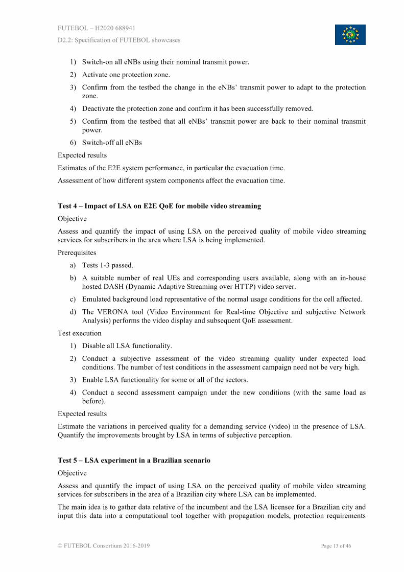
The main idea is to gather data relative of the incumbent and the LSA licensee for a Brazilian city and input this data into a computational tool together with propagation models, protection requirements
FUTEBOL – H2020 688941
D2.2: Specification of FUTEBOL showcases
© FUTEBOL Consortium 2016-2019 Page 14 of 46
and sharing rules to obtain the Radio Environment Map (REM) for the defined area, which consists in a set of parameters like allowed operating frequency and EIRP for each location. The LSA repository will be then populated with this REM, in a way that the real Brazilian scenario will be emulated on the VTT testbed.
Figure 1 illustrates the architecture for this test.
Figure 1: Test 5 architecture. The LSA repository is input with the REM of a Brazilian city, thus a Brazilian scenario is emulated on VTT testbed.
Prerequisites
a) Tests 1-3 passed.
b) REM regarding a Brazilian scenario has been obtained using the developed computational tool.
c) The LSA Repository has been populated with the generated Brazilian REM.
d) A suitable number of real UE and corresponding users available, along with an in-house hosted DASH video server.
e) Emulated background load representative of the normal usage conditions for the cell affected.
f) The VERONA tool [7] (Video Environment for Real-time Objective and subjective Network Analysis) performs the video display and subsequent QoE assessment.
Test execution

FUTEBOL – H2020 688941
D2.2: Specification of FUTEBOL showcases
© FUTEBOL Consortium 2016-2019 Page 15 of 46
1) Disable all LSA functionality.
2) Conduct a subjective assessment of the video streaming quality under expected load conditions. The number of test conditions in the assessment campaign need not be very high.
3) Enable LSA functionality for some or all of the sectors.
4) Conduct a second assessment campaign under the new conditions (with the same load as before).
Expected results
Estimate the variations in perceived quality for a demanding service (video) in the presence of LSA in a Brazilian scenario. Quantify the improvements brought by LSA in terms of subjective perception.
2.3 Integration with FUTEBOL federation and control framework
In this section, we present some considerations on the integration of the VTT testbed, used in this experiment, in the FUTEBOL federation:
• This experiment will use real LTE base stations with a trial license from the Finnish regulatory authority, therefore only a limited set of configuration parameters can be changed through the federated service.
• The LTE base stations are not available all the time, due to power consumption and produced heat. To provide testbed through federation require reservations well ahead of the actual testing – human involvement might be required for provisioning the testbed (e.g., to turn on the base stations).
• QoE measurement of the increased performance provided by the LSA requires UEs capable of carrier aggregation at the same location with the LTE base stations.
2.4 Expected results and impact
• Test and validate the system architecture, protocols and interfaces defined within the standardization process of LSA in ETSI RRS where incumbents are PMSE (e.g. wireless cameras) operating in the 2.3-2.4 GHz band or 3.4-3.5 GHz band.
• Measure the evacuation time of an LTE eNB in response to the incumbent's evacuation request for the LSA band and the impact of LSA operation on LTE. We expect an increased QoE for E2E services, with the following considerations:
o Evacuation time depends heavily on the exact type of LTE base station that is used.
o QoE increase measurement requires carrier aggregation from the user equipment to show increased performance (otherwise LSA connection is on/off).
• Assess the quality of video streaming under varying traffic load conditions, with and without LSA. The QoE assessment will be run both in Europe and in Brazil.
• Present to ANATEL the outcome of the experiment, so to discuss the LSA approach as an alternative to promote a more efficient use of radio spectrum in Brazil.
FUTEBOL – H2020 688941
D2.2: Specification of FUTEBOL showcases
© FUTEBOL Consortium 2016-2019 Page 16 of 46
2.5 Roadmap and partners’ role
Stage 1 (test 1, 2 and 3)
Test and validate the system architecture, protocols and interfaces defined within the standardization process of LSA in ETSI RRS where incumbents are PMSE (e.g. wireless cameras) operating in the 2.3-2.4 GHz band or 3.4-3.5 GHz band (VTT/IT/INTEL).
Stage 2 (test 4)
Measure the evacuation time of an LTE eNB in response to the incumbent's evacuation request for the LSA band and the impact of LSA operation on LTE; we expect an increased QoE for E2E services (VTT).
Assess the quality of video streaming under varying traffic load conditions, with and without LSA. The QoE subjective experiment will be run both in Europe and in Brazil (UFRGS).
Stage 3 (test 5)
Define the target band and incumbents for the Brazilian scenario (UFC).
Define the area at a Brazilian city that will be emulated at VTT – Finland (UFC).
Acquire the data (base station coordinates, transmit power, etc.) regarding the incumbent and LSA licensee at the defined area (UFC).
Define the propagation model and protection requirements for generation of the REM (UFC).
Develop a source code using a programming language to generate the REM based on the acquired data (UFC).
Get access to the VTT testbed LSA repository (API) (VTT/UFC).
Populate the LSA repository with the generated Brazilian REM (VTT/UFC).
Perform tests to assess the impact of LSA in the QoS and QoE for the Brazilian scenario using the VERONA tool (VTT/UFC).
Present to ANATEL the outcome of the experiment, so to promote a more efficient use of radio spectrum in Brazil, based on the LSA approach (UFC/UFRGS).
FUTEBOL – H2020 688941
D2.2: Specification of FUTEBOL showcases
© FUTEBOL Consortium 2016-2019 Page 17 of 46
3 EXPERIMENT 2.1 – HETEROGENEOUS WIRELESS-OPTICAL NETWORK MANAGEMENT WITH SDN AND VIRTUALIZATION
3.1 Objectives of experiment 2.1
The objective of this experiment is to show the dynamic adaptation of integrated optical wireless networks, considering three parts: wireless access, optical access, and metro/core. In the wireless part, virtual machines will be set up to perform processing in the backhaul and fronthaul using SDR. The optical access will be implemented using a Passive Optical Network (PON), including the use of logical connections. Also, in the metro and core network parts, SDN and virtualization mechanisms are aimed at establishing wavelength paths. More particularly, this experiment will:
• Demonstrate new methods of dynamically changing the split of radio functionality, between fronthaul and backhaul, in a Cloud Radio Access Network (RAN) environment.
• Demonstrate the impacts and benefits of deploying a common control plane for heterogeneous networks, with wireless SDR elements and fixed SDN elements.
• Demonstrate the benefits and impacts of using new methods of dynamically migrating an application server near to end-users, depending on application demand.
• Explore the tradeoff between network load gains and processing delay introduced by coded caching.
• Explore how device-to-device (D2D) communication as well as coded caching may be used to alleviate the operator's network, and how such dynamicity will impact the management of the optical and wireless parts of the network.
3.2 Experimentation methodology
This experiment is comprised of three stages: 1) dynamic switching between backhaul and fronthaul, 2) migration of video servers closer to the wireless customers, and 3) D2D with coded caching. Such stages represent steps in the implementation of logic parts of a unified view, requiring the integration of decisions induced by different network layers, i.e., the PHY, MAC and application layers. The experimentation methodology for each of the three stages is described below.
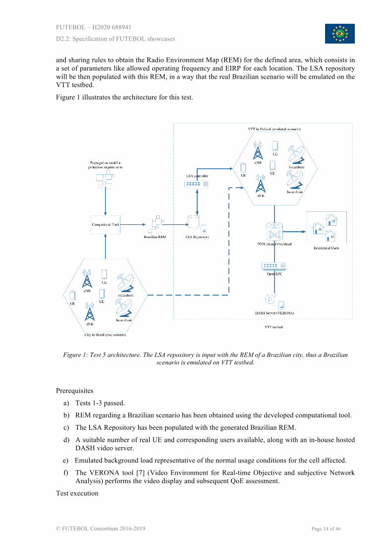
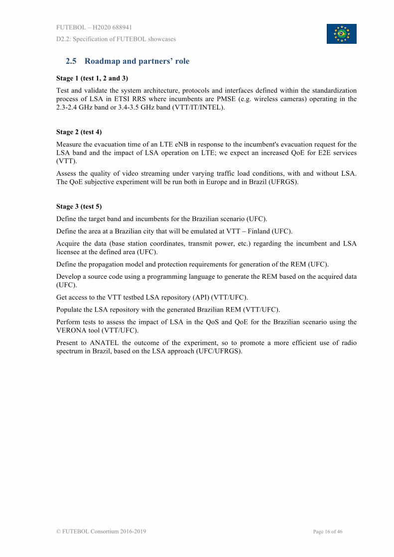
Stage 1: Split radio processing
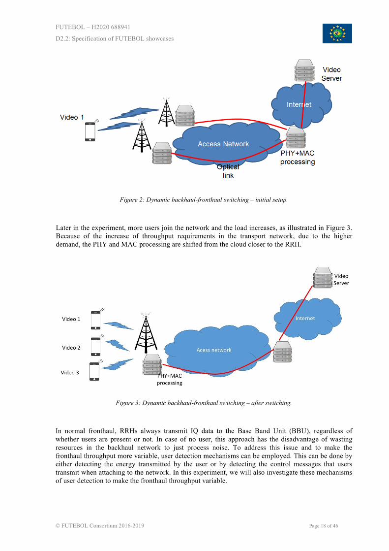
When the network has few clients, the provider's network is set up to process all the MAC and PHY data in the cloud. In this stage, the experiment's initial setup is described in Figure 2. In this setup, a user downloads a video from a Remote Radio Head (RRH), where the baseband processing is performed in a remote server, through the use of fronthaul technology.
FUTEBOL – H2020 688941
D2.2: Specification of FUTEBOL showcases
© FUTEBOL Consortium 2016-2019 Page 18 of 46
Figure 2: Dynamic backhaul-fronthaul switching – initial setup.
Later in the experiment, more users join the network and the load increases, as illustrated in Figure 3. Because of the increase of throughput requirements in the transport network, due to the higher demand, the PHY and MAC processing are shifted from the cloud closer to the RRH.
Figure 3: Dynamic backhaul-fronthaul switching – after switching.
In normal fronthaul, RRHs always transmit IQ data to the Base Band Unit (BBU), regardless of whether users are present or not. In case of no user, this approach has the disadvantage of wasting resources in the backhaul network to just process noise. To address this issue and to make the fronthaul throughput more variable, user detection mechanisms can be employed. This can be done by either detecting the energy transmitted by the user or by detecting the control messages that users transmit when attaching to the network. In this experiment, we will also investigate these mechanisms of user detection to make the fronthaul throughput variable.

FUTEBOL – H2020 688941
D2.2: Specification of FUTEBOL showcases
© FUTEBOL Consortium 2016-2019 Page 19 of 46
Stage 2: Network Functions Virtualization (NFV)
NFV concepts (e.g., virtualization, migration, scalability, orchestration, etc.) will also be explored in this experiment. NFV deals with the virtualization of network entities (e.g. cache servers, proxies, firewalls, eNodeBs). Being virtual entities, those can be moved to different sectors of the network. This is depicted in Figure 4, where we have a video being served by a server in Brazil. The network controllers (e.g., wireless and optical network controllers) sense the high demand in Europe, as depicted in Figure 5, then the entire video server could be cloned in a data centre in Europe, as depicted in Figure 6. This would require significant bandwidth, hence the use of fibre optics, to transfer the virtual machine's contents. At the same time, the clients need to be redirected to connect to the new service location.
After the cloning is complete and the clients are redirected, the optical paths should be re-configured to address the much smaller demand on the core network. In this stage, the video server can be viewed as an elastic middle box, since it acts as a relay and transcoder between the live source of the video and the remote viewers dynamically adapting to the demand. The Network Orchestrator and the Service Orchestrator need to work together and are both responsible for simultaneously optimizing the service metrics and network resource usage.
Figure 4: Video server migration – initial setup.
Figure 5: Video server migration – congestion detection.
FUTEBOL – H2020 688941
D2.2: Specification of FUTEBOL showcases
© FUTEBOL Consortium 2016-2019 Page 20 of 46
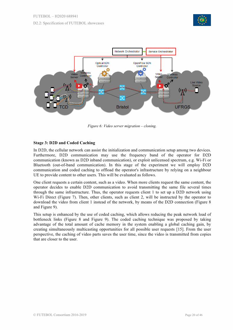
Figure 6: Video server migration – cloning.
Stage 3: D2D and Coded Caching
In D2D, the cellular network can assist the initialization and communication setup among two devices. Furthermore, D2D communication may use the frequency band of the operator for D2D communication (known as D2D inband communication), or exploit unlicensed spectrum, e.g. Wi-Fi or Bluetooth (out-of-band communication). In this stage of the experiment we will employ D2D communication and coded caching to offload the operator's infrastructure by relying on a neighbour UE to provide content to other users. This will be evaluated as follows.
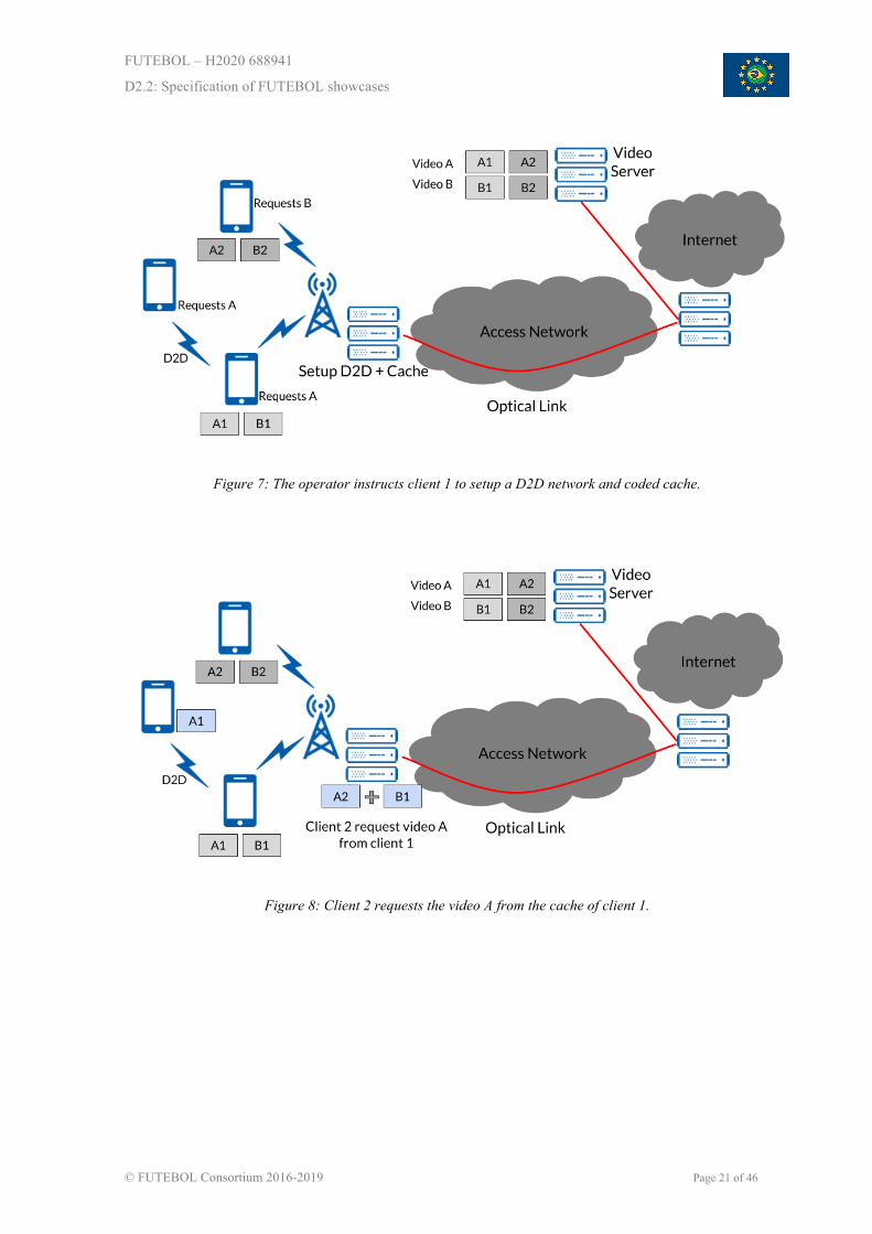
One client requests a certain content, such as a video. When more clients request the same content, the operator decides to enable D2D communication to avoid transmitting the same file several times through the same infrastructure. Thus, the operator requests client 1 to set up a D2D network using Wi-Fi Direct (Figure 7). Then, other clients, such as client 2, will be instructed by the operator to download the video from client 1 instead of the network, by means of the D2D connection (Figure 8 and Figure 9).
This setup is enhanced by the use of coded caching, which allows reducing the peak network load of bottleneck links (Figure 8 and Figure 9). The coded caching technique was proposed by taking advantage of the total amount of cache memory in the system enabling a global caching gain, by creating simultaneously multicasting opportunities for all possible user requests [15]. From the user perspective, the caching of video parts saves the user time, since the video is transmitted from copies that are closer to the user.
FUTEBOL – H2020 688941
D2.2: Specification of FUTEBOL showcases
© FUTEBOL Consortium 2016-2019 Page 21 of 46
Figure 7: The operator instructs client 1 to setup a D2D network and coded cache.
Figure 8: Client 2 requests the video A from the cache of client 1.

FUTEBOL – H2020 688941
D2.2: Specification of FUTEBOL showcases
© FUTEBOL Consortium 2016-2019 Page 22 of 46
Figure 9: Video A delivered to clients 1 and 2 (client 1 relays, after decoding, the missing part of video A to client 2); and video B delivered to client 3.
3.3 Integration with FUTEBOL federation and control framework
As an experiment that will span multiple testbeds, experimenters will have to interact with the federation framework for the reservation of optical and wireless slices. These slices will be composed of wireless resources, such as virtual machines with SDR equipment attached in the case of the TCD testbed, or optical resources, such as a wavelength path in the case of the UNIVBRIS testbed.
Besides the interaction with the federation framework, this experiment will also interact with the FUTEBOL control framework. This control framework will be responsible to deploy the relevant VNFs required by the experiment and to provide the orchestration framework that will reconfigure each part of the network according to the number of users as well as their demands. For example, the FUTEBOL control framework might be responsible for deploying the wireless video clients for QoE measurement based on the VERONA tool or deploying/migrating the video streaming servers based on DASH.
The NFV Manager, described in D4.1, will hold different VM disk images that will be required for performing the experiment. Below are listed the different virtual functions required by the experiment, and their relevance:
• Linux-based Video Server: to run DASH video service for video clients.
• Linux-based Video Client: such as VERONA from UFRGS.
• Caching algorithms to be deployed at the video server.
• Optical SDN Controller: to control SDN-enabled optical switches.
• GNURadio/srsLTE/OpenAirInterface: software to process wireless signals and implement the wireless technologies required for experimentation.
FUTEBOL – H2020 688941
D2.2: Specification of FUTEBOL showcases
© FUTEBOL Consortium 2016-2019 Page 23 of 46
• Generic Linux: to run monitoring and service orchestration (migrating and cloning) mechanisms.
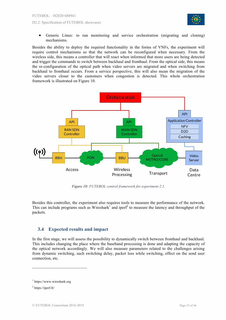
Besides the ability to deploy the required functionality in the forms of VNFs, the experiment will require control mechanisms so that the network can be reconfigured when necessary. From the wireless side, this means a controller that will react when informed that more users are being detected and trigger the commands to switch between backhaul and fronthaul. From the optical side, this means the re-configuration of the optical path when video servers are migrated and when switching from backhaul to fronthaul occurs. From a service perspective, this will also mean the migration of the video servers closer to the customers when congestion is detected. This whole orchestration framework is illustrated on Figure 10.
Figure 10: FUTEBOL control framework for experiment 2.1.
Besides this controller, the experiment also requires tools to measure the performance of the network. This can include programs such as Wireshark1 and iperf2 to measure the latency and throughput of the packets.
3.4 Expected results and impact
In the first stage, we will assess the possibility to dynamically switch between fronthaul and backhaul. This includes changing the place where the baseband processing is done and adapting the capacity of the optical network accordingly. We will also measure parameters related to the challenges arising from dynamic switching, such switching delay, packet loss while switching, effect on the send user connection, etc.
1 https://www.wireshark.org 2 https://iperf.fr/
FUTEBOL – H2020 688941
D2.2: Specification of FUTEBOL showcases
© FUTEBOL Consortium 2016-2019 Page 24 of 46
In the second stage, the video servers will be migrated closer to the customers. We will measure the latency of the connection before and after the migration. We will also measure the core network throughput. It is expected that this throughput will be reduced, showing that such a scheme can be beneficial to operators. We also expect a reduction in jitter, thus improving the quality of the connection.
The third stage presents a solution based on the improved usage of the wireless spectrum. We will employ D2D communication and coded caching to avoid duplicate downloads of the same content, reducing the throughput necessary at the core network. The main metrics to be improved are the bandwidth usage at the core network as well as the transmission time at the clients.
This experiment will span across multiple layers – from PHY to Application – and across multiple network segments – from access to core. Because of the practical implementation of such a broad system, this experiment will demonstrate the impact that such dynamic operations have on real life applications.
3.5 Roadmap and partners’ role
Stage 1
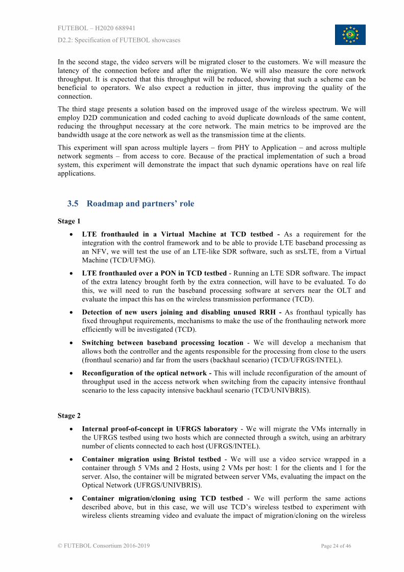
• LTE fronthauled in a Virtual Machine at TCD testbed - As a requirement for the integration with the control framework and to be able to provide LTE baseband processing as an NFV, we will test the use of an LTE-like SDR software, such as srsLTE, from a Virtual Machine (TCD/UFMG).
• LTE fronthauled over a PON in TCD testbed - Running an LTE SDR software. The impact of the extra latency brought forth by the extra connection, will have to be evaluated. To do this, we will need to run the baseband processing software at servers near the OLT and evaluate the impact this has on the wireless transmission performance (TCD).
• Detection of new users joining and disabling unused RRH - As fronthaul typically has fixed throughput requirements, mechanisms to make the use of the fronthauling network more efficiently will be investigated (TCD).
• Switching between baseband processing location - We will develop a mechanism that allows both the controller and the agents responsible for the processing from close to the users (fronthaul scenario) and far from the users (backhaul scenario) (TCD/UFRGS/INTEL).
• Reconfiguration of the optical network - This will include reconfiguration of the amount of throughput used in the access network when switching from the capacity intensive fronthaul scenario to the less capacity intensive backhaul scenario (TCD/UNIVBRIS).
Stage 2
• Internal proof-of-concept in UFRGS laboratory - We will migrate the VMs internally in the UFRGS testbed using two hosts which are connected through a switch, using an arbitrary number of clients connected to each host (UFRGS/INTEL).
• Container migration using Bristol testbed - We will use a video service wrapped in a container through 5 VMs and 2 Hosts, using 2 VMs per host: 1 for the clients and 1 for the server. Also, the container will be migrated between server VMs, evaluating the impact on the Optical Network (UFRGS/UNIVBRIS).
• Container migration/cloning using TCD testbed - We will perform the same actions described above, but in this case, we will use TCD’s wireless testbed to experiment with wireless clients streaming video and evaluate the impact of migration/cloning on the wireless

FUTEBOL – H2020 688941
D2.2: Specification of FUTEBOL showcases
© FUTEBOL Consortium 2016-2019 Page 25 of 46
networks (UFRGS/TCD).
• Container migration/cloning between TCD and Bristol - We will migrate/clone the containers running the video server between two separate testbeds in the same continent, connected through an optical link, using full optical-wireless integration (UFRGS/TCD/UNIVBRIS).
• Container migration between Bristol and Brazil - We will migrate the containers running the video server between two separate testbeds in different continents, connected through an optical link, using full optical-wireless integration (UFRGS/UNIVBRIS).
Stage 3
• Installation of an LTE implementation on USRPs - Stage 3 requires a working implementation of 3G/4G in order to accept eNodeB clients. We will investigate which implementation (OpenAirInterface, srsLTE, OpenBTS, OpenEPC, OpenLTE) performs best in the FUTEBOL UFMG testbed (TCD/UFMG).
• Proof-of-concept of a D2D connection on the testbed - We will create a D2D connection among the tested devices, using Wi-Fi Direct (UFMG/INTEL).
• Implementation and test of required changes in video client and server platforms for coded caching - Once D2D and LTE are up and running and the operator is able to instruct eNodeBs to create D2D networks, the clients and servers will be enhanced with coded caching (UFC/UFRGS).
• Integration of the video client and server platforms for coded caching - (UFC/UFMG/UFRGS).
• Integration of the D2D network with the LTE implementation - This step will integrate the D2D and LTE in the same devices, which will act as the client in the experiment (UFMG).
• Integration of D2D network and coded caching - (UFMG/UFC/UFRGS).
FUTEBOL – H2020 688941
D2.2: Specification of FUTEBOL showcases
© FUTEBOL Consortium 2016-2019 Page 26 of 46
4 EXPERIMENT 2.2 – REAL-TIME REMOTE CONTROL OF ROBOTS OVER A WIRELESS-OPTICAL SDN-ENABLED INFRASTRUCTURE
4.1 Objectives of experiment 2.2
The main focus of experiment 2.2 is to evaluate the impact of SDN and cloud computing technologies in systems running real-time applications with low E2E latency and high bandwidth requirements. Particularly, we aim to integrate diverse technologies (e.g., SDN, NFV and edge computing) to meet these stringent network requirements by bridging communication and cloud computing ecosystems and exploiting the use of a converged control framework and federated resources.
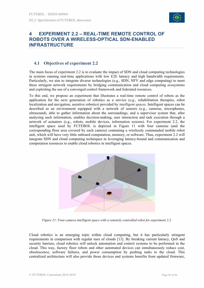
To this end, we propose an experiment that illustrates a real-time remote control of robots as the application for the next generation of robotics as a service (e.g., rehabilitation therapies, robot localization and navigation, assistive robotics) provided by intelligent spaces. Intelligent spaces can be described as an environment equipped with a network of sensors (e.g., cameras, microphones, ultrasound), able to gather information about the surroundings, and a supervisor system that, after analysing such information, enables decision-making, user interaction and task execution through a network of actuators (e.g., robots, mobile devices, information screens). For experiment 2.2, the intelligent space used by FUTEBOL is depicted in Figure 11 with four cameras (and the corresponding floor area covered by each camera) containing a wirelessly commanded mobile robot unit, which will have very little onboard computation, memory, or software. Thus, experiment 2.2 will integrate SDN and cloud computing techniques in leveraging latency-bound and communication and computation resources to enable cloud robotics in intelligent spaces.
Figure 11: Four-camera intelligent space with a remotely controlled robot for experiment 2.2.
Cloud robotics is an emerging topic within cloud computing, but it has particularly stringent requirements in comparison with regular uses of clouds [13]. By breaking current latency, QoS and security barriers, cloud robotics will unlock automation and control systems to be performed in the cloud. This way, factory floor robots and other automated devices can simultaneously reduce cost, obsolescence, software failures, and power consumption by pushing tasks to the cloud. This centralized architecture will also provide those devices and systems benefits from updated firmware,
FUTEBOL – H2020 688941
D2.2: Specification of FUTEBOL showcases
© FUTEBOL Consortium 2016-2019 Page 27 of 46
storage and processing for big data applications as well as synchronized operations. More important in cloud computing, however, is the access to plentiful resources to perform complex real-time control algorithms computation unlocked by E2E low latency networking.
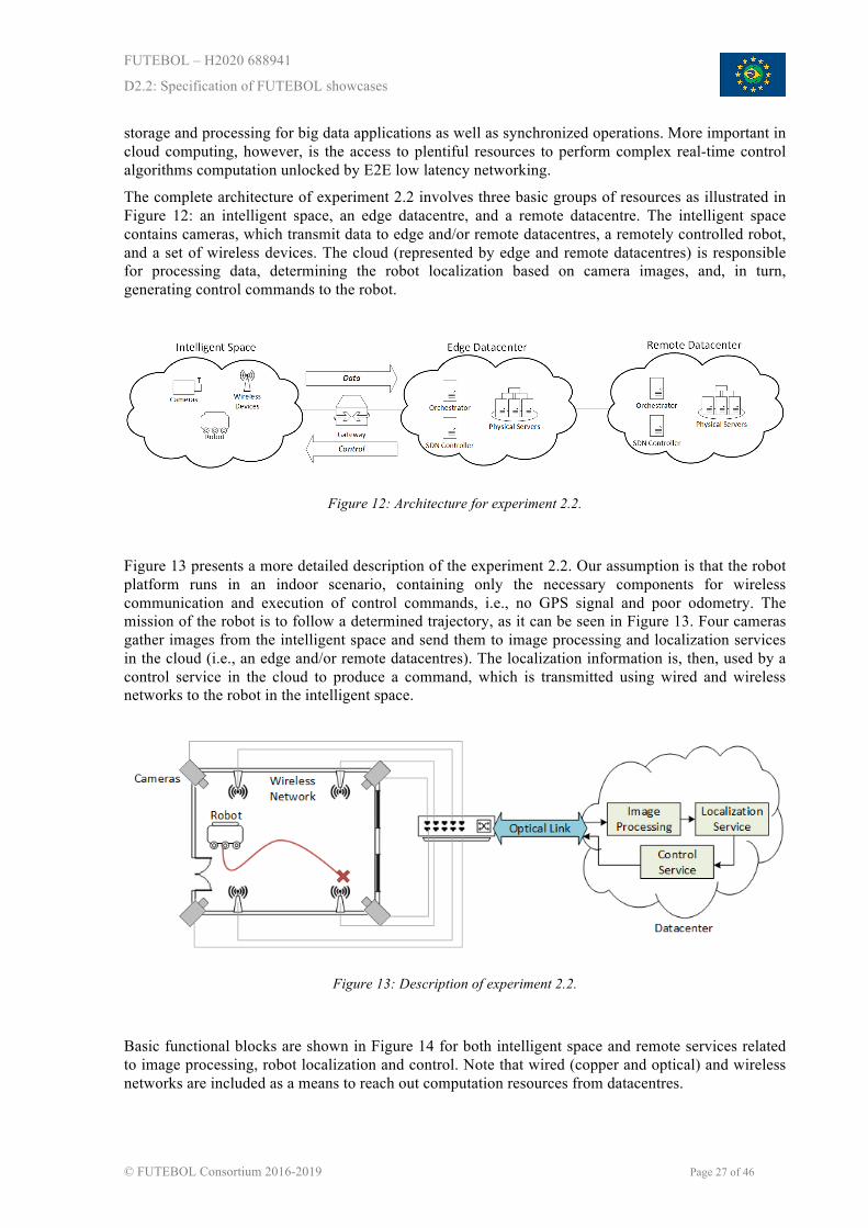
The complete architecture of experiment 2.2 involves three basic groups of resources as illustrated in Figure 12: an intelligent space, an edge datacentre, and a remote datacentre. The intelligent space contains cameras, which transmit data to edge and/or remote datacentres, a remotely controlled robot, and a set of wireless devices. The cloud (represented by edge and remote datacentres) is responsible for processing data, determining the robot localization based on camera images, and, in turn, generating control commands to the robot.
Figure 12: Architecture for experiment 2.2.
Figure 13 presents a more detailed description of the experiment 2.2. Our assumption is that the robot platform runs in an indoor scenario, containing only the necessary components for wireless communication and execution of control commands, i.e., no GPS signal and poor odometry. The mission of the robot is to follow a determined trajectory, as it can be seen in Figure 13. Four cameras gather images from the intelligent space and send them to image processing and localization services in the cloud (i.e., an edge and/or remote datacentres). The localization information is, then, used by a control service in the cloud to produce a command, which is transmitted using wired and wireless networks to the robot in the intelligent space.
Figure 13: Description of experiment 2.2.
Basic functional blocks are shown in Figure 14 for both intelligent space and remote services related to image processing, robot localization and control. Note that wired (copper and optical) and wireless networks are included as a means to reach out computation resources from datacentres.

FUTEBOL – H2020 688941
D2.2: Specification of FUTEBOL showcases
© FUTEBOL Consortium 2016-2019 Page 28 of 46
Figure 14: Intelligent space network and datacentre elements involved in experiment 2.2.
Figure 15 illustrates how the interval between image frames taken from the intelligent space will dictate deadlines for both network latency and services. Basically, all the steps shown in Figure 15 should happen within this interval, otherwise when the control command reaches the robot the localization information is no longer accurate and deviation from the planned trajectory will occur. Note that both network and datacentre infrastructures will impose bottlenecks in terms of throughput and latency to the remote control of robots. Thus, network classic performance indicators are important metrics to be assessed alongside with the trajectory error, which is the distance between the current robot position and the defined trajectory in a given instant of time.
Another important consideration is that a more complex trajectory or a lower error tolerance requires more accuracy in the robot localization, which can be accomplished by increasing the camera frame rate and, consequently, increasing the bandwidth demand. However, a higher camera frame rate decreases the interval between image frames and requires a faster answer from the control loop, decreasing the acceptable E2E latency. Thus, the application can combine realistic traffic scenarios that will challenge FUTEBOL control framework with conflicting capacity/latency requirements.
Figure 15: Interval between frames setting deadlines for information acquisition, processing and feedback to robot.
To deal with the described issues, experiment 2.2 will tackle stringent latency and bandwidth requirements by orchestrating both SDN-enabled networks and elastic resources in cloud computing. SDN traffic engineering in fibre-wireless and datacentre networks can make the most of available networking resources. Besides, the scalability of cloud computing can be exploited to instantiate multiple processing units running on VMs or containers across different physical servers (or even
FUTEBOL – H2020 688941
D2.2: Specification of FUTEBOL showcases
© FUTEBOL Consortium 2016-2019 Page 29 of 46
different datacentres across the FUTEBOL federation).
Robot mobility will also allow to link the ongoing 5G discussions in standards bodies to experiment 2.2. The ITU has defined three use cases for services in 5G [14], namely, enhanced mobile broadband (eMBB), massive machine type communications (mMTC), and ultra-reliable and low-latency communications (URLLC). Experiment 2.2 challenges fits into the URLLC use case, which is described as: “This use case [URLLC] has stringent requirements for capabilities such as throughput, latency and availability. Some examples include wireless control of industrial manufacturing or production processes, remote medical surgery, distribution automation in a smart grid, transportation safety, etc.” [14].
4.2 Experimentation methodology
The research questions proposed in D2.1 are answered through a methodology that encompasses five stages. In the first, we use an existing local intelligent space setup with conventional network to deploy the experiment as a baseline for current support of real-time applications. Throughout the remainder stages, the local setup is connected to the datacentre and the experiment incrementally incorporates new techniques to provide real-time remote control of robots.
The experimental methodology in experiment 2.2 will perform four different tests to assess our proposed solutions. As explained in the previous section, camera frame rate and robot trajectory complexity are key for simultaneously stress tolerance to latency and throughput demands.
Therefore, the tests (T) planned are as follows:
• T1: Simple trajectory (robot) and low frame rate (cameras).
• T2: Simple trajectory (robot) and high frame rate (cameras).
• T3: Complex trajectory (robot) and low frame rate (cameras).
• T4: Complex trajectory (robot) and high frame rate (cameras).
Four metrics (M) will be used to assess the performance of each test as follows:
• M1: The error between the desired and performed trajectory.
• M2: The throughput and packet loss between cameras and image processing units.
• M3: The time to process the images and to generate the robot control signals.
• M4: The total response time, defined as the time between images capture and robot reaction.
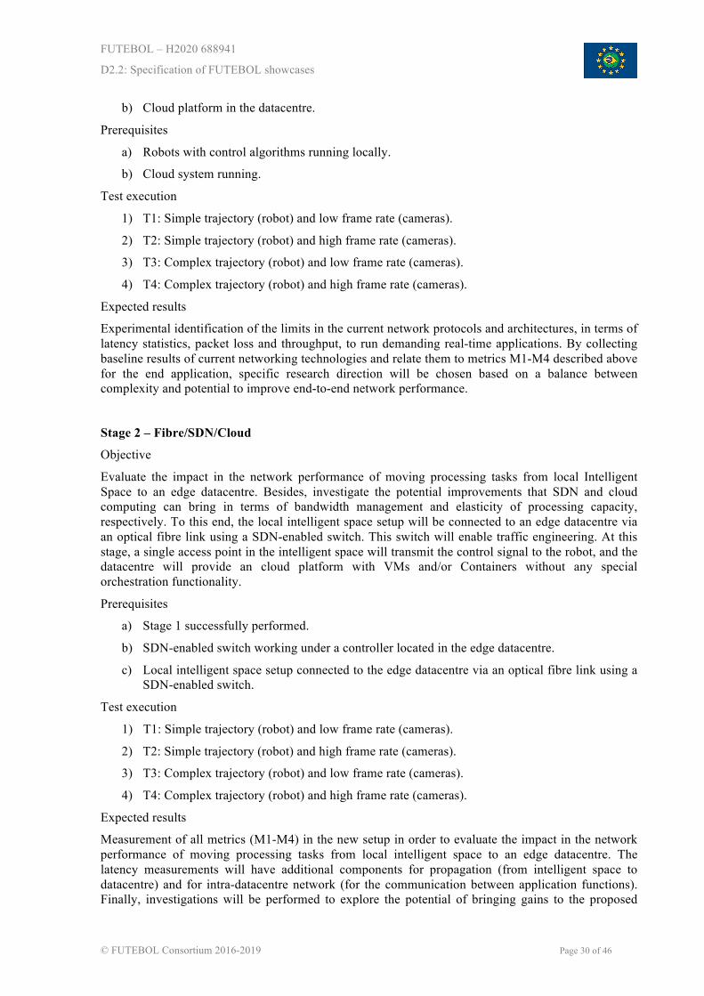
Stage 1 – Conventional Networking and Cloud Platform
Objective
At this stage, the intelligent space will not be connected to the datacentre. The local intelligent space setup will be separately tested to produce baseline network measurements, bottlenecks and E2E network requirements. This stage will provide experimental confirmation of dominant latency elements and other bottlenecks which need to be tacked to unlock stringent real-time applications. In parallel, the application functions with control and image processing algorithms will be moved to a cloud platform in the datacentre in order to investigate how they can be implemented and deployed.
Experimental setup
a) Local intelligent space containing: one access point, one robot, a set of computers, a L2 switch, and four cameras.
FUTEBOL – H2020 688941
D2.2: Specification of FUTEBOL showcases
© FUTEBOL Consortium 2016-2019 Page 30 of 46
b) Cloud platform in the datacentre.
Prerequisites
a) Robots with control algorithms running locally.
b) Cloud system running.
Test execution
1) T1: Simple trajectory (robot) and low frame rate (cameras).
2) T2: Simple trajectory (robot) and high frame rate (cameras).
3) T3: Complex trajectory (robot) and low frame rate (cameras).
4) T4: Complex trajectory (robot) and high frame rate (cameras).
Expected results
Experimental identification of the limits in the current network protocols and architectures, in terms of latency statistics, packet loss and throughput, to run demanding real-time applications. By collecting baseline results of current networking technologies and relate them to metrics M1-M4 described above for the end application, specific research direction will be chosen based on a balance between complexity and potential to improve end-to-end network performance.
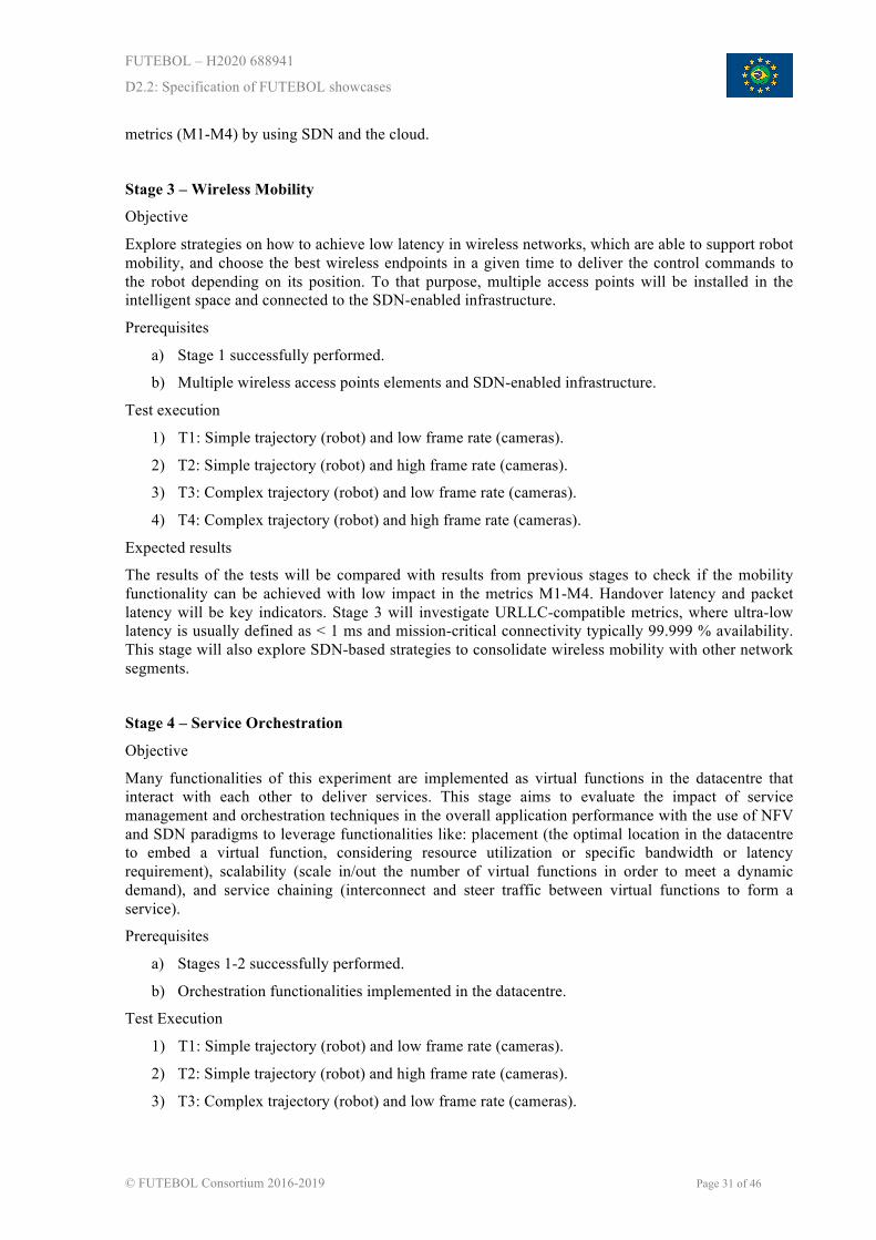
Stage 2 – Fibre/SDN/Cloud
Objective
Evaluate the impact in the network performance of moving processing tasks from local Intelligent Space to an edge datacentre. Besides, investigate the potential improvements that SDN and cloud computing can bring in terms of bandwidth management and elasticity of processing capacity, respectively. To this end, the local intelligent space setup will be connected to an edge datacentre via an optical fibre link using a SDN-enabled switch. This switch will enable traffic engineering. At this stage, a single access point in the intelligent space will transmit the control signal to the robot, and the datacentre will provide an cloud platform with VMs and/or Containers without any special orchestration functionality.
Prerequisites
a) Stage 1 successfully performed.
b) SDN-enabled switch working under a controller located in the edge datacentre.
c) Local intelligent space setup connected to the edge datacentre via an optical fibre link using a SDN-enabled switch.
Test execution
1) T1: Simple trajectory (robot) and low frame rate (cameras).
2) T2: Simple trajectory (robot) and high frame rate (cameras).
3) T3: Complex trajectory (robot) and low frame rate (cameras).
4) T4: Complex trajectory (robot) and high frame rate (cameras).
Expected results
Measurement of all metrics (M1-M4) in the new setup in order to evaluate the impact in the network performance of moving processing tasks from local intelligent space to an edge datacentre. The latency measurements will have additional components for propagation (from intelligent space to datacentre) and for intra-datacentre network (for the communication between application functions). Finally, investigations will be performed to explore the potential of bringing gains to the proposed
FUTEBOL – H2020 688941
D2.2: Specification of FUTEBOL showcases
© FUTEBOL Consortium 2016-2019 Page 31 of 46
metrics (M1-M4) by using SDN and the cloud.
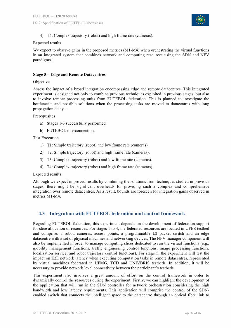
Stage 3 – Wireless Mobility
Objective
Explore strategies on how to achieve low latency in wireless networks, which are able to support robot mobility, and choose the best wireless endpoints in a given time to deliver the control commands to the robot depending on its position. To that purpose, multiple access points will be installed in the intelligent space and connected to the SDN-enabled infrastructure.
Prerequisites
a) Stage 1 successfully performed.
b) Multiple wireless access points elements and SDN-enabled infrastructure.
Test execution
1) T1: Simple trajectory (robot) and low frame rate (cameras).
2) T2: Simple trajectory (robot) and high frame rate (cameras).
3) T3: Complex trajectory (robot) and low frame rate (cameras).
4) T4: Complex trajectory (robot) and high frame rate (cameras).
Expected results
The results of the tests will be compared with results from previous stages to check if the mobility functionality can be achieved with low impact in the metrics M1-M4. Handover latency and packet latency will be key indicators. Stage 3 will investigate URLLC-compatible metrics, where ultra-low latency is usually defined as < 1 ms and mission-critical connectivity typically 99.999 % availability. This stage will also explore SDN-based strategies to consolidate wireless mobility with other network segments.
Stage 4 – Service Orchestration
Objective
Many functionalities of this experiment are implemented as virtual functions in the datacentre that interact with each other to deliver services. This stage aims to evaluate the impact of service management and orchestration techniques in the overall application performance with the use of NFV and SDN paradigms to leverage functionalities like: placement (the optimal location in the datacentre to embed a virtual function, considering resource utilization or specific bandwidth or latency requirement), scalability (scale in/out the number of virtual functions in order to meet a dynamic demand), and service chaining (interconnect and steer traffic between virtual functions to form a service).
Prerequisites
a) Stages 1-2 successfully performed.
b) Orchestration functionalities implemented in the datacentre.
Test Execution
1) T1: Simple trajectory (robot) and low frame rate (cameras).
2) T2: Simple trajectory (robot) and high frame rate (cameras).
3) T3: Complex trajectory (robot) and low frame rate (cameras).
FUTEBOL – H2020 688941
D2.2: Specification of FUTEBOL showcases
© FUTEBOL Consortium 2016-2019 Page 32 of 46
4) T4: Complex trajectory (robot) and high frame rate (cameras).
Expected results
We expect to observe gains in the proposed metrics (M1-M4) when orchestrating the virtual functions in an integrated system that combines network and computing resources using the SDN and NFV paradigms.
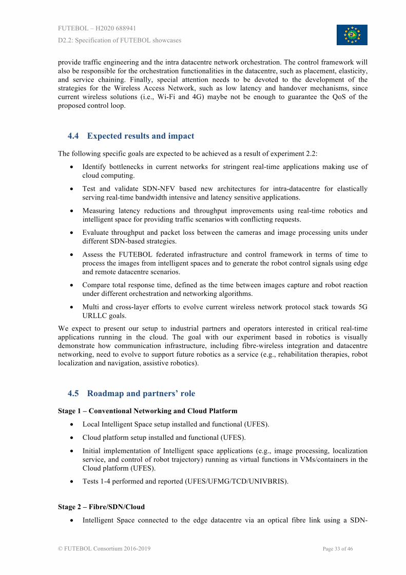
Stage 5 – Edge and Remote Datacentres
Objective
Assess the impact of a broad integration encompassing edge and remote datacentres. This integrated experiment is designed not only to combine previous techniques exploited in previous stages, but also to involve remote processing units from FUTEBOL federation. This is planned to investigate the bottlenecks and possible solutions when the processing tasks are moved to datacentres with long propagation delays.
Prerequisites
a) Stages 1-3 successfully performed.
b) FUTEBOL interconnection.
Test Execution
1) T1: Simple trajectory (robot) and low frame rate (cameras).
2) T2: Simple trajectory (robot) and high frame rate (cameras).
3) T3: Complex trajectory (robot) and low frame rate (cameras).
4) T4: Complex trajectory (robot) and high frame rate (cameras).
Expected results
Although we expect improved results by combining the solutions from techniques studied in previous stages, there might be significant overheads for providing such a complex and comprehensive integration over remote datacentres. As a result, bounds are foreseen for integration gains observed in metrics M1-M4.
4.3 Integration with FUTEBOL federation and control framework
Regarding FUTEBOL federation, this experiment depends on the development of federation support for slice allocation of resources. For stages 1 to 4, the federated resources are located in UFES testbed and comprise: a robot, cameras, access points, a programmable L2 packet switch and an edge datacentre with a set of physical machines and networking devices. The NFV manager component will also be implemented in order to manage computing slices dedicated to run the virtual functions (e.g., mobility management functions, traffic engineering control functions, image processing functions, localization service, and robot trajectory control functions). For stage 5, the experiment will test the impact on E2E network latency when executing computation tasks in remote datacentres, represented by virtual machines federated in UFMG, TCD and UNIVBRIS testbeds. In addition, it will be necessary to provide network level connectivity between the participant’s testbeds.
This experiment also involves a great amount of effort on the control framework in order to dynamically control the resources during the experiment. Firstly, we can highlight the development of the application that will run in the SDN controller for network orchestration considering the high bandwidth and low latency requirements. This application will comprise the control of the SDN-enabled switch that connects the intelligent space to the datacentre through an optical fibre link to
FUTEBOL – H2020 688941
D2.2: Specification of FUTEBOL showcases
© FUTEBOL Consortium 2016-2019 Page 33 of 46
provide traffic engineering and the intra datacentre network orchestration. The control framework will also be responsible for the orchestration functionalities in the datacentre, such as placement, elasticity, and service chaining. Finally, special attention needs to be devoted to the development of the strategies for the Wireless Access Network, such as low latency and handover mechanisms, since current wireless solutions (i.e., Wi-Fi and 4G) maybe not be enough to guarantee the QoS of the proposed control loop.
4.4 Expected results and impact
The following specific goals are expected to be achieved as a result of experiment 2.2:
• Identify bottlenecks in current networks for stringent real-time applications making use of cloud computing.
• Test and validate SDN-NFV based new architectures for intra-datacentre for elastically serving real-time bandwidth intensive and latency sensitive applications.
• Measuring latency reductions and throughput improvements using real-time robotics and intelligent space for providing traffic scenarios with conflicting requests.
• Evaluate throughput and packet loss between the cameras and image processing units under different SDN-based strategies.
• Assess the FUTEBOL federated infrastructure and control framework in terms of time to process the images from intelligent spaces and to generate the robot control signals using edge and remote datacentre scenarios.
• Compare total response time, defined as the time between images capture and robot reaction under different orchestration and networking algorithms.
• Multi and cross-layer efforts to evolve current wireless network protocol stack towards 5G URLLC goals.
We expect to present our setup to industrial partners and operators interested in critical real-time applications running in the cloud. The goal with our experiment based in robotics is visually demonstrate how communication infrastructure, including fibre-wireless integration and datacentre networking, need to evolve to support future robotics as a service (e.g., rehabilitation therapies, robot localization and navigation, assistive robotics).
4.5 Roadmap and partners’ role
Stage 1 – Conventional Networking and Cloud Platform
• Local Intelligent Space setup installed and functional (UFES).
• Cloud platform setup installed and functional (UFES).
• Initial implementation of Intelligent space applications (e.g., image processing, localization service, and control of robot trajectory) running as virtual functions in VMs/containers in the Cloud platform (UFES).
• Tests 1-4 performed and reported (UFES/UFMG/TCD/UNIVBRIS).
Stage 2 – Fibre/SDN/Cloud
• Intelligent Space connected to the edge datacentre via an optical fibre link using a SDN-
FUTEBOL – H2020 688941
D2.2: Specification of FUTEBOL showcases
© FUTEBOL Consortium 2016-2019 Page 34 of 46
enabled switch (UFES).
• Control application for traffic engineering in the SDN switch running in the datacentre (UFES).
• Cloud IaaS platform with Virtual Machines and/or Containers installed and functional in the datacentre (UFES).
• Intelligent space applications (e.g., image processing, localization service, and control of robot trajectory) migrated to the Cloud platform and tested (UFES).
• Tests 1-4 performed and reported (UFES/UFMG/TCD/UNIVBRIS).
Stage 3 – Wireless Mobility
• Multiple wireless access points elements and SDN-enabled infrastructure installed in the intelligent space (UFES).
• Strategies tested for low latency and handover mechanisms (UFES/INTEL).
• Tests 1-4 performed and reported (UFES/UFMG/TCD/UNIVBRIS).
Stage 4 – Service Orchestration
• Placement techniques implemented in the datacentre (UFES).
• Scalability techniques implemented in the datacentre (UFES).
• Service chaining of virtual functions implemented in the datacentre (UFES).
• Service Orchestrator implemented and integrated with a SDN Controller (UFES/UNIVBRIS).
• Tests 1-4 performed and reported (UFES/UFMG/TCD/UNIVBRIS).
Stage 5 – Edge and Remote Datacentres
• Testbeds interconnected and connectivity tested (UFES/UFMG/TCD/UNIVBRIS).
• Testbeds allow the orchestration of VMs in the federation (UFES/UFMG/TCD/UNIVBRIS).
• Tests 1-4 performed and reported (UFES/UFMG/TCD/UNIVBRIS).
Partners will be gradually involved from stage 2 onwards to integrate the local setup at UFES with other federated resources, especially to enable service orchestration in remote datacentres. Control framework efforts will be initially shared between UFES and UNIVBRIS. Then, finally remote datacentre will be integrated via specialized VM provision and control also at UFMG and TCD in stage 5.

FUTEBOL – H2020 688941
D2.2: Specification of FUTEBOL showcases
© FUTEBOL Consortium 2016-2019 Page 35 of 46
5 EXPERIMENT 3.1 – ADAPTIVE CLOUD/FOG FOR IOT ACCORDING TO NETWORK CAPACITY AND SERVICE LATENCY REQUIREMENTS
5.1 Objectives of experiment 3.1
Cloud Computing (CC) is a paradigm that integrates cloud and edge devices, such as computers and smart phones as well as sensors and actuators of the Internet of Things (IoT). CC allows the augmentation of constrained resources in edge devices, such as processing, storage, and battery autonomy, by using cloud services. The augmented resources available at the cloud enable edge devices to execute more sophisticated versions of key applications and services, such as mobile learning, e-commerce, and sound/image recognition. Tasks in CC are partially performed in edge devices and partially computed in the cloud. Thus, the network that interconnects edge devices and the cloud impacts the proper execution of CC applications and services. This network is usually composed of wired segments in the core, using a fibre optical medium, and wireless links at the edge to communicate with mobile devices. We refer to this combination of wireline and wireless network resources as converged networks. In this work, we discuss the allocation of computing and networking resources in a converged network, illustrating the relevant issues through the testbed implementation of a smart lighting IoT application.
In a converged network, resources, e.g., equipment, processing, and spectrum, within optical and wireless networks are pooled together to be used and shared by network operators and users. Among these resources, the processing power within a converged network is maintained at data centres to be consumed for different purposes, such as processing the workload of wireless networks or applications. These workloads must be processed considering their QoS requirements, such as latency and response time that must be met, otherwise incurring in performance degradation or even connection disruption. To meet these QoS requirements in converged networks, the processing power has been gradually distributed within the infrastructure using concepts of the fog computing paradigm.
In fog computing the processing resources can be centralized or distributed within the network through the usage of Micro Data Centers (MDCs) that are closer to the edge, where mobile devices and smart objects lie. The MDC proximity to the edge decreases the usage of core infrastructures, such as optical links, and the network latency by providing a closer pool of processing resources to mobile devices and smart objects. Decreasing the network latency is crucial for mobile devices and smart objects applications, such as real-time systems, whose performance is measured in terms of response time, e.g., the time to issue a voice/sign command until the real-time system perform an action in the user's environment, such as turning on the lights of a room. In converged networks, fog computing becomes fundamental for mobile devices and smart objects’ applications to meet QoS requirements to decrease latency, mainly in terms of response time.
In this sense, we assess the usage of fog computing in converged networks to meet QoS requirements from real-time systems, highlighting its pros and cons. The impact of fog computing is assessed in a real-time system for people with special needs using speech and sign language to issue commands to a smart light system. This assessment is performed considering two main metrics, latency and response time. MbDSAS and VERONA, are management tool for network infrastructures adaptation that will be used to decide whether an MDC is required and to measure the latency of the converged network. The response time, in turn, will be measured considering the time that a voice/sign language command is captured by an IoT device until the Lamp controller perform an action. Finally, we compare the different positioning of processing resources inside the network assessing the gains of such approach for real-time applications in converged networks.

FUTEBOL – H2020 688941
D2.2: Specification of FUTEBOL showcases
© FUTEBOL Consortium 2016-2019 Page 36 of 46
5.2 Experimentation methodology
The methodology for experiment 3.1 includes the scenario depicted in Figure 16, where a user is able to control a set of smart light bulbs, through either sign language or voice command, located at the laboratory Winet in UFMG. Both commands are going to be processed in an optical network at UNIVBRIS. MbDSAS, a computing routine orchestrator at UNIVBRIS, will delegate, if necessary, the processing of the information collected by smart objects to different Fog tiers. The result of the computing routine is sent back, triggering the actuator to perform actions affecting the lights. The scenario captures the main idea of the wireless/optical convergence by the interplay of Cloud and Fog. Considering augmented reality in IoT, a management platform can collect information from smart objects and mobile devices, create events based on thresholds/commands, and store the results for statistical studies. In this scenario, the components are:
• Data collection (sign-language and audio).
• Data processing (Fog or Cloud computing).
• Computing routine delegation (MbDSAS).
• Event creation based on monitoring results (turn lights on/off, change color, control intensity).
• Data Storage in the Cloud.
Figure 16: Experiment scenario that allows the experimenter to control the lights via either voice or sign-language command.
The experiment research questions are answered through a methodology that encompasses three stages, which are depicted below.
Stage 1
• Manual delegation of the management solution. The different fog tiers considered will be evaluated without inserting intelligence on the management solution to interchange the
FUTEBOL – H2020 688941
D2.2: Specification of FUTEBOL showcases
© FUTEBOL Consortium 2016-2019 Page 37 of 46
computation positioning between fog tiers. This way we will be able to evaluate each wireless and optical segment that composes the converged network without considering the migration of computation.
• Aims to answer the first research question of this experiment: o “How do the latency constraints of wireless/optical network impact the IoT devices?”
• Uses latency/response time as Key Performance Indicators (KPIs).
Stage 2
• Automated delegation of the solution. In this stage the stimuli caused by the optical wireless segments will be considered to migrate and optimise the performance of the converged networks.
• Aims to answer the second research question of this experiment: o “How can fog and cloud computing support IoT services in a converged
wireless/optical network?” • Uses latency/response time, jitter and throughput as KPIs.
Stage 3
• Multiple cloud orchestration. In this stage two or more cloud providers will be considered to concurrently exploit the fog. Considering the concurrence, our objective will be to load balance multiple clouds to exploit the fog, optimising the IoT applications execution.
The main goal of experiment 3.1 is to evaluate, by means of different Fog computing tiers, the performance of the IoT application in terms of network characteristics, e.g., latency, jitter, and throughput; as well as response time, when either voice or sign language commands are issued. Specifically, the voice and sign command processing can be performed in different Fog computing tiers: 1) tier 0 is the MiniPc/Gateway (VM-Local); 2) tier 1 is the FUTEBOL facility Server (VM-Server); and 3) tier 2 is the remote cloud at UNIVBRIS (Cloud). Using a tool named VERONA, the end-to-end network KPIs are measured in real-time in both segments, wireless and optical. The measurement starts from the moment that a command is captured and processed, until the moment when the light bulb reacts (i.e., changes its colour or its brightness intensity). We use Docker version 1.5.1 [16] to deploy the main routines in the optical segment; Ubuntu version 14.04 is used as the operating system for the VM.
5.3 Integration with FUTEBOL federation and control framework
The integration of experiment 3.1 in the FUTEBOL federation will be made by the allocation of the following resources, necessary to setup an experiment:
• IoT devices, such as cameras, microphones and IoT gateways. The user of this experiment needs to specify their location, i.e., where in the FUTEBOL federation these devices will be located. The resources will be replicated in any of the FUTEBOL testbeds involved in this experiment.
• VMs needed to host the speech and signal processing services in the cloud of fog computing sites.
• Network links between all the FUTEBOL sites participating in the experiment.
• As an extension to the previous FIBRE and Fed4FIRE specifications, in this experiment it will be necessary to specify a new RSpec for allocating IoT devices. The main information in this RSpec will be the type of IoT device (microphone, camera or IoT gateway) to be used and its

FUTEBOL – H2020 688941
D2.2: Specification of FUTEBOL showcases
© FUTEBOL Consortium 2016-2019 Page 38 of 46
location.
FUTEBOL sites available to host VMs for voice and signal processing services in the experiment setup are also needed to be specified in an RSpec, as well as the network links between them. It is not required to the user of the experiment 3.1 to specify service level agreements to the network links (bandwidth, jitter or latency, for example). This management is an internal task for the experiment, considering the resources reserved to the experiment, done by MbDSAS or any other network performance management tool. Given the resources reserved by the user, MbDSAS is responsible to manage them according to the network conditions and, if necessary, it can also bring the speech and signal processing service closer to the IoT devices.
5.4 Expected results and impact
The experiment will validate the smart lighting system architecture (integration between IoT devices, Gateways, Fogs, and Clouds), especially considering the wireless/optical convergence. We will measure QoS, and possibly map it to QoE in the scenario described above (Brazil-EU connection, Fog-Cloud integration) based on the metrics described below.
• Response time: This metric is of special importance for the experiment since smart objects may have to react to environment stimuli, such as a user’s gestures, in a short amount of time. When the response time grows inadvertently, a perceptive degradation in his/her experience can be noticed. In this case, the dissatisfaction of the user may exist due to a latency over 150 ms.
• Processing time: Interval during which a command is received at the Fog/Cloud and processed.
• Throughput/capacity: Since the number of IoT devices is expected to be very large, the capacity of a link will be affected by the burst of data generated and transmitted by them, which may create contention for the link.
• Packet loss/Packet error rate (PER): This is also an important metric for this experiment due to the amount of data transmitted. Packet errors and losses directly impact the used link capacity due to the need for retransmission and processing.
• Jitter: This metric is related to the variation of the delay between packets, due to network congestion, queuing, or errors. This is relevant since the link between the Fogs and Cloud may not be a dedicated one, so there may be congestion in the link, increasing jitter.
The impact of IoT in optical and wireless links are assessed through the results of the experiment. The main goal of the prototype system is to show that both voice and sign language commands can be continuously and reliably carried via wireless/optical network links to be processed in different places in the network.
The data being processed in different fogs includes audio and vectorised data for hand gestures. Audio files are big compared to the vectorised data of the hand gestures. Also, the audio processing uses voice recognition, which is a heavy-duty process, whereas the gesture processing, using vectorised data processing, represents a lighter type of processing. In this direction, the performance of different voice recognition software in our IoT application will be assessed, the impact of using different hand movements to activate the lights so that usability levels are measured for disabled people will be considered as well and also the impact of VM migration in different network tiers will be analysed.
Currently, we measure network latency and identify its impact on the response time of voice/sign language recognition systems in a Cloud computing converged network.
FUTEBOL – H2020 688941
D2.2: Specification of FUTEBOL showcases
© FUTEBOL Consortium 2016-2019 Page 39 of 46
5.5 Roadmap and partners’ role
This experiment is composed by the following activities:
• Purchase of equipment for development of a small-scale version of the experiment.
• Research about existing Convergent Networks, monitoring systems, implementation, metrics to utilize.
• Development of a small demo, representing a small version of this experiment, in order to evaluate its feasibility and to start identification of bugs and bottlenecks.
• Write a paper about the findings of the small demo, as well as what was extracted about Fog/Cloud computing for IoT.
• Further improvements of the demonstration, as well as an expansion in the usage (not only smart lights) and/or in the number of equipment used (add other facilities).
• Implement and test algorithms for delegation and orchestration of computing routines and also VM migration between Cloud and different Fog tiers.
• Compare computed routines in different scenarios of Fog and Cloud.
• Write a paper about the experiment and the integration of Fog and Cloud computing for IoT.
• Deploy and validate the final version of the experiment, correcting bugs if necessary.
All partners involved in experiment 3.1 will generally contribute with research, development, and implementation of this experiment as well as writing papers and demonstrations. Moreover, each partner will have some specific tasks as described next.
UFRGS will deploy optical and wireless facilities to execute the experiment. UFRGS coordinates the effort during the whole experiment life-cycle. Also, UFRGS will provide the tools VERONA and MbDSAS for network monitoring and computing routines delegation in IoT.
UFMG will deploy IoT facilities based on real-time applications such as smart-light controlled by voice commands. UFMG is the major player responsible for all the demonstration.
UFC is the major user of experiment 3.1. UFC will be in charge of reviewing the literature in Fog/Cloud to perform the interplay between these approaches using MbDSAS as computing routine delegation platform.
UFES will provide optical facilities to test backhauling exchange of information and its impact in a functional converged wireless/optical network.
UNIVBRIS will provide optical and cloud European facilities to deploy CC providers during the deployments of demonstration and experimentation. Also, as the optical expert will provide feedback for monitoring systems involving fibre segments of the converged network of experiment 3.1.
TCD, as the expert in converged network deployments, will help in the coordination, research, implementation, and deployment of the whole experiment life-cycle.
INTEL will contribute with its expertise to the planned papers and will support the creation of the survey on the state of the art of the literature and standardization bodies’ status regarding fog and cloud issues.

FUTEBOL – H2020 688941
D2.2: Specification of FUTEBOL showcases
© FUTEBOL Consortium 2016-2019 Page 40 of 46
6 EXPERIMENT 3.2 – RADIO-OVER-FIBER FOR IOT ENVIRONMENT MONITORING
6.1 Objectives of experiment 3.2
The goal of this experiment is to set up a robust and flexible environmental monitoring platform at UNICAMP, using IoT devices over an optical infrastructure through RoF technology. The idea is to gather and measure environment-related data, such as temperature, humidity, noise, air pollution, levels of CO emissions, and so on, in order to provide data for developing and supporting a plethora of IoT applications. In this way, the main objectives include:
• Efficient data reporting – IoT devices are responsible to gather and measure environment-related data as well as send them to a central entity for further processing and analysing. To do so, a multi-hop protocol must be employed due to the short-range communication present in these devices. In this way, we will assess existing multi-hop protocols for wireless networks and analyse them to identify which one fits best our platform. Such protocols need to avoid unnecessary transmissions as well as maximize coverage to provide a better network usage.
• Suitable modulation and generation process – RoF technology enables the modulation and generation of signals to be done in a central site, from where by means of optical fibre the signals are distributed to the simplified antenna stations. RoF emerges as a powerful candidate for robust wireless backhaul due to its advantages: simple configuration, transparency for modulation format and radio protocols. It is responsible for modulating RF signals into the optical fibre as well as demodulate the signals received through the fibre to RF signals. Such process can be analogue (RoF) or digitized (D-RoF), in which analogue RF signals are converted to digital serial bit stream before transmission over optical fibre link. Therefore, we will compare the performance of RoF and D-RoF process describing the advantages and drawback of each process to employ a suitable one and do not introduce an undesired latency which potentially can degrade system performance.
• Real-time remote reconfiguration – the IoT devices will gather and measure different environment-related data, but all IoT devices do not have to report the same data and these measures may not be reported at the same time, i.e., different devices can measure different environment-related data and each measure can be reported with a different periodicity. Furthermore, some applications and partners do not have interest in a specific measure, and consequently can avoid such report. In this way, to enable an easy reconfiguration to each application and partner according to specific needs, a real-time remote configuration mechanism should be deployed. This reconfiguration mechanism needs to create a profile to each application or partner, so to store the configuration provided from each one, and to report the measures according to each profile.
• Data analysis – measurements reported by each IoT device, according to each profile, are stored in a database to be further analysed. In this way, each profile will be capable to access its specific measurement reports to be visualized in real-time. Moreover, historical data can be provided as well filters can be applied to improve the data analysis.
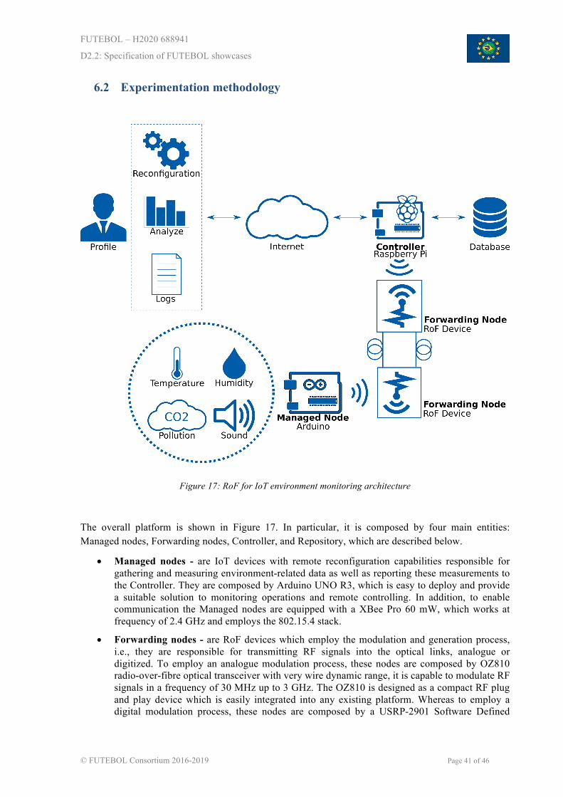
FUTEBOL – H2020 688941
D2.2: Specification of FUTEBOL showcases
© FUTEBOL Consortium 2016-2019 Page 41 of 46
6.2 Experimentation methodology
Figure 17: RoF for IoT environment monitoring architecture
The overall platform is shown in Figure 17. In particular, it is composed by four main entities: Managed nodes, Forwarding nodes, Controller, and Repository, which are described below.
• Managed nodes - are IoT devices with remote reconfiguration capabilities responsible for gathering and measuring environment-related data as well as reporting these measurements to the Controller. They are composed by Arduino UNO R3, which is easy to deploy and provide a suitable solution to monitoring operations and remote controlling. In addition, to enable communication the Managed nodes are equipped with a XBee Pro 60 mW, which works at frequency of 2.4 GHz and employs the 802.15.4 stack.
• Forwarding nodes - are RoF devices which employ the modulation and generation process, i.e., they are responsible for transmitting RF signals into the optical links, analogue or digitized. To employ an analogue modulation process, these nodes are composed by OZ810 radio-over-fibre optical transceiver with very wire dynamic range, it is capable to modulate RF signals in a frequency of 30 MHz up to 3 GHz. The OZ810 is designed as a compact RF plug and play device which is easily integrated into any existing platform. Whereas to employ a digital modulation process, these nodes are composed by a USRP-2901 Software Defined

FUTEBOL – H2020 688941
D2.2: Specification of FUTEBOL showcases
© FUTEBOL Consortium 2016-2019 Page 42 of 46
Radio (SDR), which is capable of receiving and transmitting RF signals in a frequency of 70 MHz to 6 GHz by using an Analog to Digital Converter (ADC) or a Digital to Analog Converter (DAC), respectively.
• Controller - is the entity with the highest level of complexity in the platform. At the controller, all the workload from the measurements reported by the IoT devices will be processed and interpreted. It is also responsible for creating and managing the profiles, enabling a remote access to reconfigure each profile according to specific needs as well as to provide an interface to access and analyse the measurements reported. It is composed by a Raspberry Pi 3 with a XBee Pro 60mW to work at the same frequency and employ the same stack of the Managed nodes.
• Repository - responsible for storing the data reported by IoT devices according to each profile configured at the Controller. It provides access to measurements reported at real-time and to a data history according to each profile.
Experiment 3.2 comprises three stages, described next.
Stage 1 - Digitized Radio over Fibre
This stage firstly tests the communication of a USRP with a managed node to determine whether it works properly and to compare the obtained results with those obtained in the Analog Radio over fibre. After that, USRPs are used as forwarding nodes to communicate with multiple managed nodes, which will simulate an IoT network and will be compared with the Analog Radio over fibre with multiple forwarding nodes.
Stage 2 - Analog Radio over Fibre
In this stage we will test the communication between one managed node and one forwarding node, allowing us to ascertain that the analogue optical transmission works properly. By comparing the results obtained using Ethernet with Digitized Radio over fibre and using optical fibre with Analog Radio over fibre, it is possible to answer the research question: “how does the latency introduced by the optical fibre impact the operation of IoT?”. If the latency is compared when using similar data traffic and measured in different usage cases, we can make a statistical analysis of them.
Stage 3 - Multiple Forwarding Nodes
A fibre splitter will be used to split the optical signal transmitted to the nodes, sending the same signal to different forwarding nodes, allowing the expansion of the network. By comparing the communication of multiple forwarding nodes tested in stage 1 and stage 3, it is possible to analyse the advantages and disadvantages of using Analog Radio over fibre to communicate with diverse IoT devices.
Based on the aforementioned architecture, the experimentation methodology goes through the following tests.
RF modulation and generation
The goal of this test is to analyse whether the Forwarding nodes are able to transmit RF signals through the optical links. To measure this, we intend to compare the RF signals received from the Managed nodes at the Forwarding nodes with the RF signals delivered to the Controller, as also compare de RF signals produced by the Controller and the RF signals delivered to the Managed nodes. Moreover, to employ a suitable transmission of RF signals through the fibre, we intend to compare the performance of the analogue process (RoF) and the digitized process (D-RoF), analysing the

FUTEBOL – H2020 688941
D2.2: Specification of FUTEBOL showcases
© FUTEBOL Consortium 2016-2019 Page 43 of 46
advantages and the drawbacks of each process for our platform. Finally, to verify how these processes will impact in the performance of the deployed platform, the delay of both processes will be analysed:
• RoF processing delay: time spent to modulate an analogue RF signal into the fibre jointly with the latency introduced by the length of the optical links and the time spent to demodulate the signals received from the optical links to analogue RF signals.
• D-RoF processing delay: time spent to convert an analogue RF signal to a serial bit stream jointly with the latency introduced by the length of the optical link and the time spent to convert the serial bit stream received to an analogue RF signal.
Remote access, real-time reconfiguration and data analysis
This test focuses on checking if other partners and/or IoT applications are able to access the platform and reconfigure it to their needs. To measure this, we need to verify whether a partner can create a specific profile to select which environment-related data each Managed node will gather and measure as well as configure the periodicity report of each measurement. In addition, to ensure the reconfiguration, the Controller needs to receive a confirmation message of each Managed node that will be reconfigured. However, in case of not receiving the confirmation message of a specific Managed node, the reconfiguration message needs to be re-sent to that node to be reconfigured. It is important to notice that the configuration of each profile can be accessed and reconfigured on-the-fly by each partner. Furthermore, an interface will be implemented to provide real-time access to the data reporting and to enable to analyse it as well as analyse the historic of data reporting of each profile. Furthermore, to provide a suitable real-time reconfiguration, the platform performance needs to be analysed. In this way, the following metrics will be evaluated:
• Total of reconfiguration messages: number of reconfiguration messages generated by the Controller to reconfigure the overall platform according to profile changes or upon creating a new profile.
• Reconfiguration response time: time spent to reconfigure the overall platform, i.e., the time reconfiguration messages take to reach the Forwarding nodes jointly with the RoF/D-RoF process and the time reconfiguration messages take to reach all specified Managed nodes. It is important to notice that in this delay is also added the time spent to re-send the reconfiguration messages to the nodes that did not confirm the receipt.
6.3 Integration with FUTEBOL federation
UFRGS will provide its testbed for this experiment, in particular the testbed slice with Radio over Fiber equipment. The testbed will allow remote users to reserve, deploy, and access such equipment. UFRGS testbed, currently is being federated and will allow worldwide experimenters to use RoF equipment combined with IoT motes nodes, in the context of this experiment.
UFRGS will have four RoF devices separated by 2 km of optical fibre to propagate analogue signals. Two IEEE 802.15.4 interfaces connected to Raspberry Pi nodes will have its signal traversing the four RoF devices and the 2 km of fibre to reach two pairs of antennas (Rx / Tx).
By using the soon-to-be federated UFRGS testbed, federated experimenters can create their own experiment from worldwide having access to different performance metrics, such as bit rate error and latency information.
6.4 Expected results and impact
The experiment will validate the proposed platform, demonstrating the impact of deploying IoT devices over an optical infrastructure through the RoF technology. In this way, the expected results include:

FUTEBOL – H2020 688941
D2.2: Specification of FUTEBOL showcases
© FUTEBOL Consortium 2016-2019 Page 44 of 46
• Evaluate different multi-hop protocols for data reporting and analyse their characteristics.
• Analyse the latency of the overall platform, assessing each particular latency, i.e. the latency of the data reporting; the latency introduced by the modulation of RF signals (RoF) as well as conversion of RF signals into serial bit stream (D-RoF) to be transmitted through the optical links; the latency introduced by the length of the optical link; and the latency of introduced to generated back the RF signals.
• Compare the efficiency of RoF and D-RoF evaluating different performance metrics. Consequently, we will be able to highlight the advantages and drawbacks of each process and provide a suitable one.
6.5 Roadmap and partners’ role
This experiment will be composed the following activities:
• Purchase the equipment to deploy a small-scale version of the experiment.
• Searching for existing multi-hop protocols to report data to be implemented for analysis in the proposed platform.
• Provide a experiment demo, which consist in a reduced version of the entire experiment to analyse its availability and to check potentials bugs and/or bottlenecks.
• Compare different protocols for multi-hop data reporting.
• Compare the platform performance with RoF and D-RoF.
• Write a paper with the results obtained from the RoF and D-RoF comparison.
• Implement the remote reconfiguration and the interface for accessing the data reporting and analyse it.
• Deploy the final version of the experiment.
• Validate the final version and correct bugs if necessary.
UNICAMP is the leading partner in this experiment, the experiment will be performed at UNICAMP premises, but replicated in the federated testbed of UFRGS. UNICAMP will drive the research and experimentation behind the experiment.
UFRGS will be responsible for replicating its platform at the university, so to exploit how it will work with different types of data such as audio and video, which will be produced by experiment 3.2. Moreover, they will be responsible to introduce the D-RoF process on the platform to provide a comparison between RoF and D-RoF.
INTEL will support the search and decision on the most suitable multi-hops protocol to adopt, will collaborate on the paper and will provide its expertise on the validation methodology to be used.
All other partners can access our platform and create and configure a profile to gather and to measure environment-related data according their needs. In addition, each partner can also access the data reporting at real-time, reconfigure its profile and also analyse the data reported through an interface provided by the platform.

FUTEBOL – H2020 688941
D2.2: Specification of FUTEBOL showcases
© FUTEBOL Consortium 2016-2019 Page 45 of 46
7 CONCLUSIONS
The use cases and especially the experiments reported in this deliverable display a wide range of capabilities available in FUTEBOL research facilities for use of partners and third party experimenters in converged wireless/optical networks. Moreover, this showcasing will increase the likelihood adoption of the results obtained in the whole FUTEBOL project by the community, industry and regulators.
This deliverable is a continuation of deliverable D2.1 – “Specification of FUTEBOL use cases, requirements, and architecture definition”, with more details in the experiments (or showcases); and it is the last deliverable of work package WP2. These experiments will be further implemented in the technical work package WP5 (and also impact WP3 and WP4).
Each of the five experiments will undergo the process of planning, platform integration, experimentation, and performance evaluation. Measurements and analysis will be carried out to evaluate the performance of the specific experiments and publicly demonstrate the benefits of the FUTEBOL research infrastructure in exploring the boundaries of wireless/optical networks. The very first results will be reported in deliverable D5.1 – “Initial experiment description and results”.
FUTEBOL – H2020 688941
D2.2: Specification of FUTEBOL showcases
© FUTEBOL Consortium 2016-2019 Page 46 of 46
REFERENCES
[1] S. Abolfazli, Z. Sanaei, E. Ahmed, A. Gani, and R. Buyya, “Cloud-based augmentation for mobile devices: Motivation, taxonomies, and open challenges,” IEEE Communications Surveys & Tutorials, 2014.
[2] M. R. Rahimi, J. Ren, C. H. Liu, A. V. Vasilakios, and N. Venkatasubramanian, “Mobile cloud computing: A survey, state of art and future directions,” Mobile Networks and Applications, 2014.
[3] M. Satyanarayanan, P. Bahl, R. Caceres, and N. Davies, “The Case for VM-Based Cloudlets in Mobile Computing,” IEEE Pervasive Computing, 2009.
[4] M. A. Marotta, L. R. Faganello, M. A. K. Schimuneck, L. Z. Granville, J. Rochol, and C. B. Both, “Managing Mobile Cloud Computing Considering Objective and Subjective Perspectives,” Elsevier Computer Networks, 2015.
[5] M. Satyanarayanan, P. Bahl, R. Caceres, and N. Davies, “The Case for VM-Based Cloudlets in Mobile Computing,” IEEE Pervasive Computing, 2009.
[6] Stéphane Gosselin, Anna Pizzinat, Xavier Grall, Dirk Breuer, Eckard Bogenfeld, Sandro Krauß, Jose Alfonso Torrijos Gijón, Ali Hamidian, Neiva Fonseca, and Björn Skubic, “Fixed and Mobile Convergence: Which Role for Optical Networks?,” J. Opt. Commun. Netw. 7, 1075-1083 (2015)
[7] “CoLisEU: Collect and analyze the quality of user wireless networks,” https://coliseu.rnp.br/, 2017, acessed in: January 5th, 2017.
[8] Marotta, M. A., Carbone, F. J., Santanna, J. J. C. de, & Tarouco, L. M. R. (2013). Through the Internet of Things – A Management by Delegation Smart Object Aware System (MbDSAS). In 2013 IEEE 37th Annual Computer Software and Applications Conference (pp. 732–741). Kyoto, Japan: IEEE.
[9] Thomas, V. A., El-Hajjar, M., & Hanzo, L. (2015). Performance Improvement and Cost Reduction Techniques for Radio Over Fiber Communications. IEEE Communications Surveys & Tutorials, 17(2), 627–670.
[10] Hong, K., Lillethun, D., Ramachandran, U., Ottenwälder, B., & Koldehofe, B. (2013). Mobile fog. In Proceedings of the second ACM SIGCOMM workshop on Mobile cloud computing - MCC ’13 (p. 15). New York, New York, USA: ACM Press.
[11] ETSI TS 103 235 V1.1.1 (2015-10) “Reconfigurable Radio Systems (RRS); System architecture and high level procedures for operation of Licensed Shared Access (LSA) in the 2 300 MHz - 2 400 MHz band”.
[12] Draft ETSI TS 103 379 V0.0.4 (2016-12) “Reconfigurable Radio Systems (RRS); Information elements and protocols for the interface between LSA Controller (LC) and LSA Repository (LR) for operation of Licensed Shared Access (LSA) in the 2300 MHz-2400 MHz band”.
[13] Kehoe, B., Patil, S., Abbeel, P., & Goldberg, K. (2015). A survey of research on cloud robotics and automation. IEEE Transactions on Automation Science and Engineering, 12(2), 398-409.
[14] ITU. (2015). Framework and Overall Objectives of the Future Development of IMT for 2020 and Beyond. Recommendation ITU-R M.2083-0.
[15] Y. Fadlallah, A. M. Tulino, D. Barone, G. Vettigli, J. Llorca and J. M. Gorce, "Coding for Caching in 5G Networks," in IEEE Communications Magazine, vol. 55, no. 2, pp. 106-113, February 2017.
[16] Merkel, Dirk. "Docker: lightweight linux containers for consistent development and deployment." Linux Journal 2014.239 (2014): 2.