D1.1 – Requirements, specifications and reference...
57
Cloud LSVA Large Scale Video Analysis EUROPEAN COMMISSION DG Communications Networks, Content & Technology Horizon 2020 Research and Innovation Programme Grant Agreement No 688099 D1.1 – Requirements, specifications and reference architecture Project funded by the European Union’s Horizon 2020 Research and Innovation Programme (2014 – 2020) Deliverable no. D1.1 Dissemination level Public Work Package no. WP 1 Main author(s) Manuel Reis-Monteiro, Marcos Nieto, Joachim Kreikemeier Co-author(s) All partners Version Nr (F: final, D: draft) F File Name D1.1 Requirements, specifications and reference architecture Project Start Date and Duration 01 January 2016, 36 months Ref. Ares(2017)533940 - 31/01/2017
Transcript of D1.1 – Requirements, specifications and reference...
Cloud LSVA
Large Scale Video Analysis
EUROPEAN COMMISSION
DG Communications Networks, Content & Technology
Horizon 2020 Research and Innovation Programme
Grant Agreement No 688099
D1.1 – Requirements, specifications and
reference architecture
Project funded by the European Union’s Horizon 2020 Research and Innovation Programme (2014 – 2020)
Deliverable no. D1.1
Dissemination level Public
Work Package no. WP 1
Main author(s) Manuel Reis-Monteiro, Marcos Nieto, Joachim Kreikemeier
Co-author(s) All partners
Version Nr (F: final, D:
draft)
F
File Name D1.1 Requirements, specifications and reference architecture
Project Start Date and
Duration
01 January 2016, 36 months
Ref. Ares(2017)533940 - 31/01/2017

D1.1
F
2
Document Control Sheet
Main author(s) or editor(s): Manuel Reis-Montero, Marcos Nieto, Joachim Kreikemeier Work area: WP 1 Document title: D1.1 – Requirements, specifications and reference architecture
Version history:
Approval:
Name Date
Prepared Manuel Reis-Montero, Marcos Nieto, Joachim Kreikemeier
2017/01/16
Reviewed Houssem Chatbri (DCU) 2017/01/24
Authorised Oihana Otaegui 2017/01/30
Circulation:
Recipient Date of submission
EC 2017/01/30
Cloud LSVA consortium 2017/01/30
Legal Disclaimer The information in this document is provided “as is”, and no guarantee or warranty is given that the information is fit for any particular purpose. The above referenced consortium members shall have no liability for damages of any kind including without limitation direct, special, indirect, or consequential damages that may result from the use of these materials subject to any liability which is mandatory due to applicable law. © 2016 by Cloud LSVA Consortium.
Version number
Date Main author Summary of changes
v0.1 2016/03/21 Manuel Reis-Montero (Valeo) Table of contents
v0.2 2016/03/22 Manuel Reis-Montero (Valeo) Suzanne Little (DCU) Marcos Nieto (Vicomtech)
Use cases and tech. requirements Ontology Video annotation
v0.3 2016/04/05 All Contributions to all sections
v0.4 2016/05/10 Manuel reis-Montero (Valeo) Review of all contents
v0.6 2016/06/15 Manuel Reis-Montero (Valeo), Marcos Nieto (Vicomtech), Phil Jordan (IBM), Brendan Rousseau (TomTom)
Contributions.
v0.7 2017/01/09 Suzana Tunij (Valeo), Marcos Nieto (Vicomtech)
Revised Table of Contents.
v0.8 2017/01/15 All Contributions
V0.9 2017/01/16 Suzana Tunij (Valeo), Marcos Nieto (Vicomtech)
Formatting and revised all sections
V0.10 2017/01/24 Houssem Chatbri (DCU) Peer Review
F 2017/01/30 Suzana Tunij (Valeo) Final version

D1.1
F
3
Abbreviations and Acronyms
Acronym Definition
SW Software
HW Hardware
ADAS Advance Driver Assistance System
NCAP New Car Assessment Programme
AEB Autonomous Emergency Braking
HAD Highly automated Driving
IoT Internet of Things
V2X Vehicle to Everything
SLAM Simultaneous Localisation and Mapping
ISO International Standardisation Organisation
CAN Controlled Area Network
RTK Real Time Kinematics
DGPS Differential GPS
FOV Field of View
SDK Software Development Kit
TOSCA Topology Orchestration Specification for Cloud Applications
PaaS Platform as a Service
NAS Network Attached Storage
OS Operative System
SQL Structured Query Language
WDP Warp speed Data Transfer
GUI Graphical User Interface
VCD Video Content Description
SCD Scene Content Description
JSON JavaScript Object Notation
ViPER Visual Information Processing for Enhanced Retrival
XML Extensible Markup Language
INS Inertial Sensors
IMU Inertial Measurement Unit
ROS Robotic Operational System
OWL Web Ontology
W3C World Wide Web Consortium
RDF Resource Description Framework

D1.1
F
4
Table of Contents Executive Summary ................................................................................................................................ 8
1. Introduction ...................................................................................................................................... 9
1.1 Purpose of Document ............................................................................................................. 9
1.2 Intended audience ................................................................................................................... 9
1.3 Related documents ................................................................................................................. 9
2. Use cases description .................................................................................................................... 10
2.1 Annotation for ADAS like application .................................................................................... 10
2.1.1 Phase 1: On Sidewalk / City Inter-urban ........................................................................... 11
2.1.2 Phase 2: On Roadway / City Inter-urban .......................................................................... 11
2.1.3 Phase 3: Realistic Combinations City / Highway .............................................................. 12
2.2 Annotation for Cartography generation ................................................................................. 12
2.2.1 Phase 1: Navigation prototype with a closed loop for traffic signs .................................... 13
2.2.2 Phase 2: Road markings and type classification .............................................................. 13
2.2.3 Phase 3: Lane navigation prototype for HAD cars with closed loop for incremental map updates .......................................................................................................................................... 14
3. Functional System Requirements for ADAS .................................................................................. 15
3.1 Car Configuration .................................................................................................................. 15
3.1.1 Requirements .................................................................................................................... 15
3.2 Measurements....................................................................................................................... 17
3.2.1 Measurement Package ..................................................................................................... 18
3.2.2 Measurement Frame ......................................................................................................... 19
3.2.3 Measurement Key-frame ................................................................................................... 21
3.2.4 Measurement fragment: frame sequence ......................................................................... 21
3.3 Scenes and Scenarios .......................................................................................................... 22
3.4 Annotations ........................................................................................................................... 23
3.4.1 Region-based Annotation .................................................................................................. 23
3.4.2 Road Reconstruction ......................................................................................................... 24
3.4.3 Functional Annotation ....................................................................................................... 24
3.4.4 Annotation Data Aggregation from multiple measurements ............................................. 26
3.4.5 Levels of Annotation Automation ...................................................................................... 27
3.4.6 Annotation Process & Quality Assurance ......................................................................... 28
4. Technical System specifications .................................................................................................... 29
4.1 General Architecture ............................................................................................................. 29
4.1.1 Infrastructure layer ............................................................................................................ 30
4.1.2 Platform layer .................................................................................................................... 30
4.1.3 Application layer ................................................................................................................ 33
4.2 Cloud Infrastructure ............................................................................................................... 36
4.2.1 Physical specifications ...................................................................................................... 36
4.2.2 Interface description .......................................................................................................... 38
4.3 Software Components ........................................................................................................... 38
D1.1
F
5
4.3.1 Web front-end .................................................................................................................... 38
4.3.2 Annotation engine ............................................................................................................. 39
4.3.3 Dataset engine .................................................................................................................. 39
4.3.4 Search engine ................................................................................................................... 40
4.3.5 Analytics engine ................................................................................................................ 41
4.3.6 Upload engine ................................................................................................................... 42
4.3.7 Tools engine ...................................................................................................................... 42
4.3.8 Pipeline engine .................................................................................................................. 43
4.4 Communication and Data Format ......................................................................................... 43
4.4.1 Physical specifications ...................................................................................................... 43
4.4.2 Interface description .......................................................................................................... 43
4.4.3 Annotation format .............................................................................................................. 44
4.5 Scene Recording Module ...................................................................................................... 47
4.5.1 Recorder capabilities ......................................................................................................... 47
4.5.2 Data compression ............................................................................................................. 48
4.5.3 Physical specification for sensors ..................................................................................... 49
4.5.4 File formats and chunking ................................................................................................. 50
4.6 Middleware and SDK’s .......................................................................................................... 51
4.6.1 RTMaps ............................................................................................................................. 51
4.6.2 Computer vision and Machine learning SDKs .................................................................. 52
4.6.3 RoadDNA .......................................................................................................................... 53
5. Ontology definition ......................................................................................................................... 54
5.1 Definition ............................................................................................................................... 54
5.2 Applications ........................................................................................................................... 54
5.3 Technology and related work ................................................................................................ 55
5.4 Example ontology .................................................................................................................. 55
5.5 Next steps ............................................................................................................................. 56
6. References ..................................................................................................................................... 57

D1.1
F
6
List of Figures
Figure 1: Pedestrian on sidewalk. ......................................................................................................... 11 Figure 2: Stopped-Slow-Braking. .......................................................................................................... 11 Figure 3: Pedestrian on Roadway. ........................................................................................................ 11 Figure 4: Overtaking & Narrow passage-detection free space. ............................................................ 11 Figure 5: Realistic combinations – Pedestrian to car. ........................................................................... 12 Figure 6: Realistic combinations – Car to car. ...................................................................................... 12 Figure 7 Traffic sign localisation ........................................................................................................... 13 Figure 8 Lane markings and road classifications .................................................................................. 14 Figure 9 Optical flow ............................................................................................................................. 14 Figure 10: Valeo test vehicle. ................................................................................................................ 15 Figure 11: Subject vehicle datum reference frame. .............................................................................. 16 Figure 12: Measurement package. ....................................................................................................... 17 Figure 13: Logical view of measurements. ........................................................................................... 19 Figure 14: Frames / Time. ..................................................................................................................... 20 Figure 15: Asynchronous nature of measurements data. ..................................................................... 20 Figure 16: Measurement key frame on pedestrian crossing. ................................................................ 21 Figure 17: Measurement fragments. ..................................................................................................... 22 Figure 18: Images and Video annotation regions. ................................................................................ 23 Figure 19: Road reconstruction. ............................................................................................................ 24 Figure 20: Automatic Emergency Braking example. ............................................................................. 24 Figure 21: Functional annotations for pedestrian crossing. .................................................................. 25 Figure 22: Functional annotations for lane change (ISO 17387:2008). ................................................ 25 Figure 23: Pedestrian crossing annotations [1]..................................................................................... 26 Figure 24: Annotations on different cameras (top: side-mirror camera, bottom: front camera). ........... 26 Figure 25: Scenes vs fragments (top: side-mirror camera, bottom: front camera). .............................. 27 Figure 26: Degrees of annotation automation. ..................................................................................... 27 Figure 27: Semi-automated annotation process. .................................................................................. 28 Figure 28: The cloud stack. ................................................................................................................... 29 Figure 29: OASIS TOSCA defines topology and orchestration definition for cloud-based applications.
.............................................................................................................................................................. 30 Figure 30: IBM Bluemix is a PaaS that works on the top of IBM SoftLayer IaaS. ................................ 31 Figure 31: Docker and Docker-compose will be used in Cloud-LSVA development stage. Docker can
be used to package CUDA-enabled heavy algorithms using computer vision or machine learning
libraries. ................................................................................................................................................. 32 Figure 32: Kubernetes: (left) cluster example; and (right) Kubernetes architecture where containerised
applications run inside pods, alongside with related volumes. One of multiple pods run inside one
node (VM).............................................................................................................................................. 33 Figure 33: Diagram of the reference architecture. ................................................................................ 33 Figure 34: Scene Content Description is a data annotation model that can host annotations from
multiple, varied sensors. ....................................................................................................................... 45 Figure 35: Elements of the VCD ........................................................................................................... 46 Figure 36: Element-wise and frame-wise internal structure of VCD. .................................................... 46 Figure 37: The type file of the VCD Relation is in this example a concept from an ontology. .............. 46 Figure 38: Annotations across different VCDs, through the VCD Matrix. ............................................. 47 Figure 39 Recording PC ........................................................................................................................ 48 Figure 40 Data acquisition and upload process .................................................................................... 49 Figure 41 File chunking ......................................................................................................................... 50 Figure 42: RoadDNA example. ............................................................................................................. 53 Figure 43: Diagram of the ontology created with the VCD elements. ................................................... 56

D1.1
F
7
List of Tables Table 1: Main Cloud-LSVA modules. .................................................................................................... 35
Table 2: Additional engines and elements provided by existing technologies. ..................................... 36
Table 3: Annotation services. ................................................................................................................ 39
Table 4: Data engine services. ............................................................................................................. 40
Table 5: Analytics services for video annotation tools. ......................................................................... 41
Table 6: Analytics services for machine learning tools. ........................................................................ 42

D1.1
F
8
Executive Summary
The aim of the Cloud-LSVA project is to develop a software platform for efficient and
collaborative semiautomatic labelling and exploitation of large-scale video data solving
existing needs for ADAS and Digital Cartography industries.
Cloud-LSVA will use Big Data Technologies to address the open problem of a lack of
software tools, and hardware platforms, to annotate petabyte scale video datasets, with the
focus on the automotive industry. Annotations of road traffic objects, events and scenes are
critical for training and testing computer vision techniques that are the heart of modern
Advanced Driver Assistance Systems and Navigation systems. Providing this capability will
establish a sustainable basis to drive forward automotive Big Data Technologies.
As part of the Cloud-LSVA project, WP1 ensures the establishment of the basis and
reference documents and procedures to be followed during the subsequent RTD tasks. The
definition activities to carry out are being deployed following the iterative development plan
explained:
• A detailed definition of user requirements collected from the end users partners and
advisors.
• Description of the use-cases and related test scenarios, which leads to the definition
of functional requirements of the system.
• A detailed definition of legal, ethical, standardisation and economical requirements
and restrictions to be considered.
• To design the Cloud-LSVA reference architecture to establish a technical
specification of the entire system.
• Description of the HW and SW components to be used during the project execution
using as basis the reference architecture, the cost and legal restrictions and the
expected interfaces and deployment platforms.
• To establish an appropriate and feasible development lifecycle and a monitor
procedure of the compliance of the defined architecture and interfaces during the
project lifespan. This is performed by the project’s Architecture Review Board (ARB).
Additionally, as a critical milestone, the specifications must include the definition, creation or
extension of existing ontologies for metadata description in the context of the selected
scenarios. For that purpose, the leading industrial partners jointly with the technical partners
have defined the ontology during the first work cycle and will revise it in subsequent cycles
for necessary updates or fine-tuning.

D1.1
F
9
1. Introduction
1.1 Purpose of Document
This document is a report containing a description of specifications of the system
requirements and a general view of the architecture of the Cloud-LSVA platform.
The main purpose of the document is to be used as a reference to consult basic design
information about the Cloud-LSVA platform. Namely, its aims are:
To provide a list of potential use-cases and test scenarios (section 0).
To define functional systems requirements (section 3).
To prescribe the car calibration-configuration (section 3.1) and the measurement
fragments (section 3.2)
To present the agreed understanding and requirements on data annotation (section
3.4).
To design the Cloud-LSVA reference architecture to establish a technical
specification of the entire system (section 4.1).
The SW and HW components that compose the Cloud-LSVA platform are described along
section 4, while section 5 describes the concept of ontology and the technologies to
implement and use it within Cloud-LSVA.
This document was defined to be an internal working document during the first iteration of
the project (first twelve months). A preliminary version was created in M3 (March 2016),
containing a basic description of use cases and functionalities. Subsequent versions were
created until M6 (June 2016), to correspond to the agreed functionalities, SW and HW
platforms, etc. During the first integration period (from M9 to M12), this document was used
as a reference to actually start integrating components. After the Cloud-LSVA prototype has
been built, during M13 the consortium have created this consolidated version of D1.1.
1.2 Intended audience
The audience of this deliverable D1.1 is open to the general public, and will serve as an
overview of the proposed technologies that define the Cloud-LSVA platform.
1.3 Related documents
This document shall be read along with some other documents that complement some of its
content, or where some references might be found.
Cloud-LSVA Technical annex: this is the original description of the Cloud-LSVA
platform, to be used as a reference and guide of general objectives.
D5.3 Cloud-LSVA Alpha prototype (report): this document contains a report of the
technical activities carried out during the first iteration of the project (1st year).
D2.1 Specification of vehicles architecture and on-board software and
hardware for recording and real-time tagging: this document extents the content
provided regarding the SW and HW components used for recording test scenes.
D3.1 Import/export interfaces and Annotation data model and storage
specification: this document contains detailed information about data formats.

D1.1
F
10
2. Use cases description
The following two sections describe the main two application domains where the Cloud-LSVA is applied: the Advanced Driver Assistance System (ADAS) and the Digital cartography use cases.
2.1 Annotation for ADAS like application
One of the aims of Cloud-LSVA is to provide support for annotation tasks irrespective of a particular functional use case. This support could take of the form of fully-to-partially automated workflows for off- and on- board processing, online tool support for user-driven annotation, as well as methods and processes to render the tasks of annotation, machine learning, etc., manageable over very large datasets of measurements. A set of exemplary use-cases will be used to help construct the framework required to support the annotation effort. In the automotive context of Advanced Driver Assistance Systems, two categories of use-cases are presented: the first category involves vulnerable road users i.e. pedestrians, and a vehicle in diverse situations. The second category centres on multiple scenarios around different vehicles involved in road traffic situations. The objective is to have a good spread of examples and measurements involving longitudinal as well as lateral control situation of the subject vehicle involved. All uses-cases are spread across the three implementation phases in the Cloud-LSVA project to reflect an increasing level of complexity. Please note that no assumptions are made about ADAS systems being testing during the data acquisition process; it is assumed that acquisition of raw data is done under naturalistic driving condition with no ADAS support. For the definition of use cases, the following two concepts are defined: (i) Vulnerable Road User Category: the focus is primarily set on vulnerable road users such as pedestrians or cyclists; (ii) Vehicle Traffic Category: the use cases involve primarily vehicle situations.

D1.1
F
11
2.1.1 Phase 1: On Sidewalk / City Inter-urban
In Phase I, the proposed use cases are borrowed from AEB NCAP car-to-pedestrian scenario, where the pedestrian is assumed to initiate road crossing from the sidewalk (near side) irrespective of occlusion state. In both situations, it is assumed that the driver of the vehicle is braking to avoid collision.
Figure 1: Pedestrian on sidewalk.
The proposed use-cases focus primarily around braking situations where the target vehicle may be stopped, slow moving or braking (similarly to NCAP car-to-car-rear scenarios). No assumption is made about the location of the vehicles (Urban, inter-urban, etc.).
Figure 2: Stopped-Slow-Braking.
2.1.2 Phase 2: On Roadway / City Inter-urban
In Phase II, pedestrians/cyclists are assumed to be on the roadway: either walking along the road in the direction of travel or crossing from the far side. For the first case, collision avoidance can either be done by steering or by braking; both maneuvers are also possible.
Figure 3: Pedestrian on Roadway.
The focus moves towards obstacle avoidance in terms of full or partial lane change. In the first case, situations, where the subject vehicle needs to carry an overtaking manoeuvre are considered. In the latter case, the subject may need to detect free space to avoid, for instance, construction work.
Figure 4: Overtaking & Narrow passage-detection free space.

D1.1
F
12
2.1.3 Phase 3: Realistic Combinations City / Highway
In Phase III, the above mentioned use cases can be merged into a single use-case. The objective here is to ensure that it is possible to annotate a complex situation.
Figure 5: Realistic combinations – Pedestrian to car.
As shown in Figure 6, complex multi-lane scenarios should be considered.
Figure 6: Realistic combinations – Car to car.
2.2 Annotation for Cartography generation
For Tom Tom, “Lane-level” navigation is an incremental step from road-navigation technology for infotainment systems towards cooperative-navigation technology for highly automated driving (HAD). It is essential to keep the map in sync with reality for lane-level navigation and even more for automated driving. Conventional map making techniques no longer meet the right level of freshness. Crowd sourcing technologies are explored as a new way of map making. These implement a near real-time loop of updating the on-board map on the basis of deviations of this map with real-time information of ca’s exo-sensors (i.e. camera, radar, LIDAR). The changes are committed to the back office to improve the next map. The process to produce map updates is automated with map-object classifiers that can run in the cloud environment for map production and can run in the vehicle system for lane positioning. Highly accurate annotation of pictures or videos is key to train the map object classifiers and achieve the goal of an ever improving map.

D1.1
F
13
2.2.1 Phase 1: Navigation prototype with a closed loop for traffic signs
This use case demonstrates an upgrade of an off-the-shelf navigation device with crowd-sourcing software that detects `speed-limit-sign` shapes in an area targeted to detect specific map updates. This traffic-sign shape is positioned and sent to the cloud system, which classifies the traffic sign in an automatic process. If sufficient observations are to create evidence that a speed-limit sign in the reference to all TomTom devices in the field. The evidence is stored in a historic database which can be used to train new algorithms. The navigation system will implement lane positioning for highway situations by tracking lane markings with the camera and matching the car position to the map. It implements an android widget providing lane guidance advices, based on the lanes available in the static map. To validate the prototype results a highly accurate ground truth is required. This could be annotated data with precise positioning.
Figure 7 Traffic sign localisation
2.2.2 Phase 2: Road markings and type classification
For this prototype, specific hardware is developed for running object classifiers within environment perception software and is connected to the IoT (Internet of things) infrastructure. It connects to the in-vehicle navigation application sub-system via wireless communication; it connects to the IoT infrastructure via V2X and cellular communication. The prototype will demonstrate improved lane navigation functionality based on fresh map data. That requires a new extended map format with lane attributes in the map that will be kept fresh on the basis of automated processing of crowd sourced data. To validate the prototype results a highly accurate ground truth is required. This could be annotated data with precise positioning.

D1.1
F
14
Figure 8 Lane markings and road classifications
2.2.3 Phase 3: Lane navigation prototype for HAD cars with closed loop for incremental map updates
In this prototype, more advanced lane positioning concepts will be integrated to support lane navigation, also in urban and rural environments by fusion of traditional positioning sensors with inputs from several visual sensors in the car and special map products for HAD cars like RoadDNA or crowdsourced point clouds. In this prototype, an incremental map update is demonstrated based on the SLAM principle. Road geometry observations of different cars of a targeted mining area are processed to an incremental map update applying SLAM techniques.
Figure 9 Optical flow
By using the above techniques, we can optimise the algorithms from both phase 1 and phase 2. That will result in an even more precise positioning of traffic signs and the position of the car on the road and its 3d environment. This prototype requires highly precise positioned landmarks.

D1.1
F
15
3. Functional System Requirements for ADAS
3.1 Car Configuration
Data acquisition process requires that all sensors are mounted and fixed to the subject vehicle. Additionally, data logging equipment is required to record the measurement to be annotated. To make sense of the recorded data it is necessary to provide an annotation system with the actual position and orientation of the sensors.
Figure 10: Valeo test vehicle.
The same goes for recorded vehicle bus messages, which need to be converted back to scalar values. As multiple partners in the Cloud-LSVA project will make recordings, it is important that a common configuration format be defined to ensure smooth operation of annotation process.
3.1.1 Requirements
Requirement: The Cloud-LSVA system shall provide a common car configuration open format to help define the various sensor/device setups in the subject vehicle. Rationale: The calibration file for the sensors (Velodyne and camera) will be provided for every recording. Requirement: The Cloud-LSVA car configuration format shall enable unique identification of the subject vehicle. Rationale: A subject vehicle used for data acquisition may be re-configured during their lifetime at the test centres. It is important for processing reasons to clearly identify the vehicle for which the configuration file has been produced for. This identification may be a VIN or proprietary serial number for the vehicle.

D1.1
F
16
Requirement: The Cloud-LSVA car configuration format shall be used to describe the naming, position and orientation (frame of reference) of all sensors and reference systems on the subject vehicle with respect to a datum reference frame on the vehicle. Rationale: A document will be provided along with the recorded file every time, the measurement and the location of the sensors. Car coordinate system will be mentioned in this document. Requirement: The Cloud-LSVA car configuration format shall define the datum as the intersection point on the rear axle with the vehicle centreline. Rationale: The distance from the back wheel axis to the Velodyne sensor is provided with the X, and Z directions as shown in Figure 8. Any changes in the mounting positions will be measured again and updated. Requirement: The Cloud-LSVA datum axis system shall follow the orientation of the axis system as defined per ISO 8855. Rationale: This axis system represents a right-handed orthogonal system of axes and determines the sense or orientation of the various vehicle motions; e.g. longitudinal (x), lateral (y) and vertical (z) translations, and roll (φ), pitch (θ), and yaw (ψ) rotations.
Figure 11: Subject vehicle datum reference frame.
Requirement: The Cloud-LSVA car configuration format shall provide the possibility of linking or embedding the intrinsic calibration of every sensor present in the subject vehicle. Rationale: Intrinsic calibration data is needed to ensure proper interpretation / correction of the measurements. Requirement: The Cloud-LSVA car configuration format shall provide the possibility of linking or embedding the necessary databases to help decode vehicle messages recorded during data acquisition Rationale: The data recorded is the data from reference Velodyne Sensor and camera sensor and the recording would be done using RTMaps software. The CAN or the FLEXRAY data is not recorded. Requirement: The Cloud-LSVA car configuration format shall enable the specification of the vehicle dimensions with respect to the datum reference frame. Rationale: Any changes in the positions of the sensors would be updated.

D1.1
F
17
Requirement: The Cloud-LSVA car configuration format shall enable the tagging of devices as either product sensor or reference sensor. Rationale: A reference sensor is a device that is used by engineers to support the engineering design effort and will not be used in the final product, e.g., RTK DGPS, or LIDAR range finders. Requirement: The Cloud-LSVA car configuration format may enable the specification of the vehicle physical properties, such as centre of gravity, inertial moments, etc., with respect to the datum reference frame. Rationale: The specification of the vehicle with the senor mounting positions are provided. Requirement: The Cloud-LSVA car configuration and linked files shall be bundled into a container with the proper manifest, or follow an open packaging standard. Rationale: This requirement is to ensure that no linked file is missed during a copy of the configuration.
3.2 Measurements
It is assumed in this document that measurements will be obtained primarily from data logging equipment installed in the subject vehicle, which ensures that the measurement data records are correctly logged with the appropriate timestamp.
Figure 12: Measurement package.
This section focuses primarily on requirements needed for the annotation process ranging from the bundling of measurements down to the indexing and delimitation of the fragments of measurement to support annotation.

D1.1
F
18
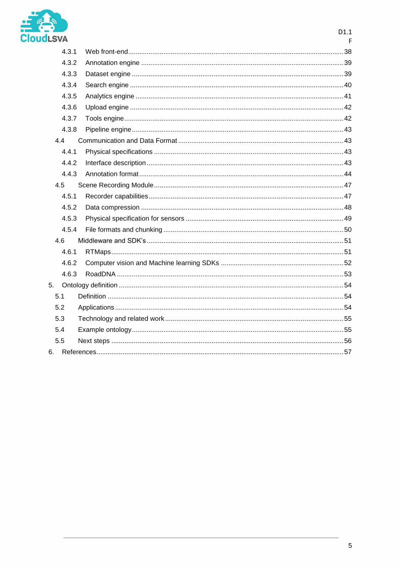
3.2.1 Measurement Package Requirement: The Cloud-LSVA project shall define or select a container format (Measurement Package) to store all relevant data pertaining to a data collection run. Rationale: A recording from the vehicle system may involve multiple files; the rationale with this requirement is to keep a recording packaged so that we can handle the measurements as a single logical package. Requirement: The Cloud-LSVA Measurement Package shall provide a manifest listing all the content available in a given Package. Any content not listed in the manifest shall be ignored and/or discarded. Rationale: This requirement is to ensure that all files pertaining to the measurements are available; it provides a fast check to ensure that processing can be executed in a cost effective way. Requirement: The Cloud-LSVA Measurement Package shall enable fast listing of all relationships between content parts and/or content external to the package. Rationale: beyond a simple check of the content, it should be possible to clearly identify the categories of measurements available for processing: sensors, reference sensors, etc. An additional check can be done to ensure that data required and marked as external content can be accessed: for example, DBC or FIBEX files required to decode bus messages; this kind of data is vehicle specific and does not require to be maintain/copied with the measurements. Requirement: The Cloud-LSVA Measurement Package shall provide a central content part to list all package properties such as vehicle identification, date and time of data capture, test campaign identification, etc. Rationale: Like an office document, it should be possible to access the “summary” properties quickly without having to process a lot of data. Requirement: The Cloud-LSVA Measurement Package shall enable storage of the package in one or more physical files or blocks. Rationale: as recording can span multiple hours, it is best practice to split the recordings into blocks. In a cloud context, the storage system may be an object store rather than a file system; to enable fast upload/download of data, blocks should have an optimal size to reduce latencies. Requirement: The Cloud-LSVA Measurement Package shall provide URL-based scheme to access content stored in a remote package; in this case no assumptions need to be made about the physical storage of content. Rationale: even if the measurements will primarily be stored and accessible as files, the Cloud-LSVA platform will live primarily on a cloud environment, where access cannot be limited to conventional file systems. Requirement: The Cloud-LSVA Measurement Package shall provide the ability to tag content stored in a remote package with pre-defined or ad-hoc categories representing the purpose for generating the measurement. Rationale: Field testing can be done different purposes: “open road” or statistical driving, track testing of specific scenarios, etc. Requirement: The Cloud-LSVA Measurement Package shall be based as far as possible on open standards. Rationale: potentially a measurement package can be archived.
D1.1
F
19
Figure 13: Logical view of measurements.
3.2.2 Measurement Frame In the context of a specific sensor measurement, a frame is uniquely defined by a combination of the sensor data, and the point-in-time the data was acquired. A discreet sequence of frames makes a measurement. For some sensors, timing and data of a frame are quite simple: for a camera, an image acquired at a given point in time, For other sensors this will be more complex; a LIDAR range finder rotating over a vertical axis will generate a discreet scan (firings) of the environment at different time intervals. From a processing perspective, a full rotation of the device would be required. A frame in this case would cover a time interval, traditionally would be assigned a time point.

D1.1
F
20
Figure 14: Frames / Time.
Requirement: The Cloud-LSVA Project shall provide guidelines or standards to define data and timing of frames for different types of sensors. Rationale: This is to ensure that there is a common understand on what constitutes a frame for all devices. In terms of frame timing, no assumptions can be made that a measurement is assigned a fixed sample time. Even in video streams for ADAS systems, the video frame rate can be variable. Additionally, no assumptions can be made that timing of one measurement matches frame-by-frame the timing of other measurements. The frame timing provides a total order over the frames of a single measurement. Correct timing across measurements is assumed to be correct and provided by the Data Acquisition System. To ensure quick navigation across frames in a single measurement, a zero-based integer index is assigned to each frame.
Figure 15: Asynchronous nature of measurements data.
The basic properties of a measurement frame are its index, its timestamp and the sensor data.

D1.1
F
21
3.2.3 Measurement Key-frame A measurement key-frame is a frame that is associated with some specify significant event. For example, a video key-frame in a pedestrian crossing situation may depict the instant when the pedestrian crosses a virtual boundary delimiting a roadside curb.
Figure 16: Measurement key frame on pedestrian crossing.
Any measurement frame can be tagged as a measurement key-frame by an annotator. The tag must follow clearly defined conventions.
3.2.4 Measurement fragment: frame sequence A measurement fragment is a continuous sequence of frames delimited by a start and an end time points, i.e., delimited by two frames. A complete measurement is then the maximum extension a fragment can have within a measurement. Measurement fragments subscribe to interval algebra such as Allen’s Interval Algebra. Measurement fragments can be manually created by an annotator or generated by an automated annotation system. For instance, a fragment may represent a road type segment such as motorway segment where the start and end frames are key-frames representing entry and exit motorway road signs; a fragment could also represent an object track for a target vehicle or pedestrian. Requirement: The Cloud-LSVA Project shall define and implement a set of operators to manipulate fragments, provide access to frames in the fragments. Rationale: The main objective to allow a set of standard operators with the same semantic to be used across the implementation of all Cloud-LSVA platform tools.

D1.1
F
22
Figure 17: Measurement fragments.
3.3 Scenes and Scenarios In theatricals plays, a scene is understood as a setting where some action or event occurs, and is often linked to some specific place and actors; a scene has a beginning and an end. In an annotation context for ADAS development, a scene represents a situation of interest to engineers to help design, train, or validate systems. For example, in the context of pedestrian detection, engineers will be interested in scenes involving pedestrians (pedestrians crossing the road, or pedestrians walking on the sidewalk), as well as scenes characterised by the absence of pedestrians such as motorway sections with no pedestrians in sight. In terms of scenario, a scene may include different variants in the motion/behaviour of the different actors. In a pedestrian ADAS context, a pedestrian may be crossing the road on a pedestrian crossing or diagonally crossing the road with obvious ground markings; alternatively, a pedestrian may halt near the curb and wait for the subject vehicle to pass before crossing. In its simplest form, scenes are tags assigned to some manually defined fragments. A fragment may be assigned multiple scene tags depending on the actor/scenario focus to the scene definition. In the Cloud-LSVA platform, one of the objectives is to provide a more advanced scene understanding concept to help data-mine existing measurements for fragments subscribing to a particular specified scene and/or scenario rules. Requirement: The Cloud-LSVA Project shall provide a clear definition to what constitutes a scene. Rationale: simple tagging is not sufficient if one tries to enable automatic recognition of scenes. An annotator or developer should be able to define the primary characteristics of scenes he/she is looking for.

D1.1
F
23
Requirement: The Cloud-LSVA Project shall explore the feasibility of mining scenes from annotated measurements. Rationale: automatic recognition of scenes is not a simple problem to solve. Requirement: The Cloud-LSVA Project shall provide a methodology and supporting tools to clearly define an ontology required to annotate and to define scene components. Rationale: NCAP test scenarios are a good example: initial focus was done on recognition of adults; the scenarios are evolving towards inclusion of children detection. An ontology service for Cloud-LSVA must provide the ability to evolve with the standards without required a costly re-adjustment of data in the cloud.
3.4 Annotations This subsection contains the description of the agreed definition of annotations. It will present a number of different types of annotations, which span the identified functional requirements, including multiple views, annotation automatisation, etc.
3.4.1 Region-based Annotation A standard approach to the manual annotation of video sequences is to delineate a region or patch of pixel and assign a label to the region for each frame. A region may take the form of a polygon or closed polyline (Figure 18: a, b, c) or a rectangle (Figure 18: d). The regions may delineate several types of regions described with one or more labels. In Figure 18a, three different labels are used to characterise the state of the lens in terms of visibility: Soiled, Blurred or Clear. This type of annotation is required to help determine the camera state. In Figure 18b&d, each polyline/rectangle is labelled as car object along with its identifier as text or colour. In Figure 18c, regions are defined at pixel-level and the overlaid colours represent the class of object: e.g. blue for cars, pink for sidewalk, purple for the road.
Figure 18: Images and Video annotation regions.
Requirement: The Cloud-LSVA Project shall capabilities to automatically/manually position/generate regions onto video frames. It shall be possible to manually modify point placements. Rationale: Annotation of regions in images and video.

D1.1
F
24
3.4.2 Road Reconstruction Road reconstruction is necessary to determine the qualitative position of objects, as well as, help determine which objects need monitoring for the ADAS functions (Car in front for Autonomous Emergency Braking).
Figure 19: Road reconstruction.
Requirement: The Cloud-LSVA Project shall capabilities to automatically segment road structures from camera data and possibly automatically label the detected regions. Rationale: Determination of qualitative position of objects and which objects need monitoring for the ADAS functions.
3.4.3 Functional Annotation Functional annotations are annotations that go beyond the simple determination of pixel regions from detection and are dependent of the type of advanced driver assistance system function being developed. As a consequence, functional annotations are pegged to a particular type of scene and particular function. As shown in Figure 20, functional annotations are based on observable measures extracted from the image/video material, such as the headway distance to the front vehicle, or relative velocity between two vehicles, from which dependent variables can be computed from, such as time-to-collision, or time-to-brake indicators. Observable measures are usually time-dependent, and will vary from frame to frame.
Figure 20: Automatic Emergency Braking example.

D1.1
F
25
In some cases, as shown in Figure 21 and Figure 22, support geometry needs to be introduced; in Figure 21, a curb line (in red) is overlaid in world coordinates to mark the boundary between sidewalk and road lane, and serves as a transition boundary. The curb line is invariant in world terms across all video frames in the scene. In Figure 22, zones 1 and 2 as well as the warning line (yellow) are positioned relative to the ego vehicle. The areas of the zones as well as the warning line position, change proportional to the ego-vehicle velocity; hence frame for frame.
Figure 21: Functional annotations for pedestrian crossing.
Figure 22: Functional annotations for lane change (ISO 17387:2008).
Lateral, longitudinal and Euclidean distances from the ego vehicle to other vehicles and/or pedestrians can be measured and used to compute different types of indicators as in the AEB example (Figure 20).

D1.1
F
26
Figure 23: Pedestrian crossing annotations [1].
In addition to geometric aspect, functional annotations also extend to individual object attributes that may be necessary to analyse specific situations. Figure 23 illustrates some aspects in the context of pedestrian protection. Important characteristics of pedestrians are: the actual class, child, adult or elderly; the action being performed by the pedestrian (walking, running, still); the direction of travel in case of movement; and head orientation. In the case of vehicle, odometry and direction of travel are also required. This additional information is then used to either compute dependent variables or establish statistics around behavioural patterns exhibited by the various actors.
3.4.4 Annotation Data Aggregation from multiple measurements Traditionally, annotations are produced for a single sensor; as multiple cameras may be embedded in the test vehicle, it is important that the individual annotated regions (on different cameras) belonging to the same objects are aggregated together. Each camera has a different position and direction and the field of view (FOV) will be different. Hence an object leaving the FOV of one camera may still be seen as another sensor (e.g., in Figure 24 on side mirror camera, the parked grey car is visible, but not on the front camera).
Figure 24: Annotations on different cameras (top: side-mirror camera, bottom: front camera).

D1.1
F
27
A scene can span different sensors; in a pedestrian crossing context (Figure 25), the pedestrian may appear first on front camera and then become visible on the right mirror camera. The annotated fragments for the scene will register the poses of the pedestrian; all events and actions are expected to be in synch, but the fragment may be of different durations and / or start/end time-points.
Figure 25: Scenes vs fragments (top: side-mirror camera, bottom: front camera).
3.4.5 Levels of Annotation Automation Currently, annotations are performed manually by a horde of workers. Although tools exist to provide support to annotation, productivity gains are still too low to enable large scale video annotation. As a result, only a relatively small amount of acquired data can be processed. This implies that the concept of annotation is tightly linked to the concept of ground-truth. Ground-truth are annotations that are considered to be “correct” and are used in training machine learning algorithms or used as test reference. Ground-truth is by its very nature bound to a quality assurance process. Current practices imply that manual workers produce ground-truth.
Figure 26: Degrees of annotation automation.
The ideal situation would be to automate the annotation generation, which itself relies on machine learning, and thus introduces false or missed detections into the annotations. The major advantage of automation is to ensure that most if not all the acquired measurements are processed and can then be indexed by annotation content even if partially incorrect. But, with the introduction of annotation automation, there must be a decoupling between annotation and ground-truth, whereby a path must be left open to “transform” annotations into ground-truth. Furthermore, annotation automation is limited by the detection functions made available to the platform. If new object classes have been identified for annotation, a horde of manual workers is then required to perform partial object annotation. Within this context, semi-automation of annotations (besides full automation) is also a major requirement to support different activities such as:
Correcting automatically generated annotations,
Annotating new object classes.
D1.1
F
28
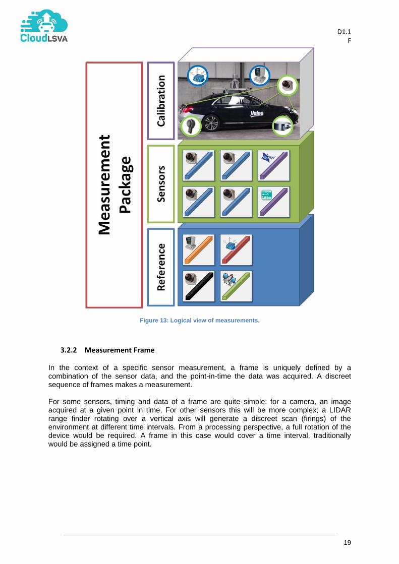
3.4.6 Annotation Process & Quality Assurance To ensure that annotations are of high-precision, a quality assurance process must be put in place to ensure compliance to a set of standard concerning the annotations. Whether the process is conducted manually or automated manner, in both cases a review process must be put in place to validate ground-truth. The particularity of automation is the added requirement that specific key performance indicators must be made available to ensure proper monitoring and assessment of annotators with regards to validating automated annotations: these kinds of indicators are called “laziness” indicators, and refer to anticipate behaviour of an annotator when reviewing / correcting annotations coming from a detection function.
Figure 27: Semi-automated annotation process.

D1.1
F
29
4. Technical System specifications
This section contains the core contribution of this deliverable, including a description of the
reference architecture of Cloud-LSVA, a list of SW components, the defined data formats,
the scene recording module, and identified 3rd Party and SDKs to be used during the
development stage.
4.1 General Architecture
One of the major aims of the Cloud-LSVA platform is to provide services and applications to
end users for annotation process. The software platform should run a cloud environment. To
ensure that each partner can develop, deploy and run the application, a cloud agnostic
environment has been selected.
Figure 28: The cloud stack.
Figure 28 shows the system stack devised for Cloud-LSVA. At the top, the Cloud-LSVA
system will be built as a Software or Application layer, where all functionality resides, and
where all modules intercommunicate using standard communication channels (e.g. RESTful
web services). The Platform layer below is composed of a set of engines that represent
technologies that can take care of scaling, optimising, deploying the Cloud-LSVA functions
while automatically managing the underlying resources. At the bottom, these resources
(computation, networking, storage), are represented by the Infrastructure Layer.

D1.1
F
30
4.1.1 Infrastructure layer In terms of infrastructure, and for development and testing purposes, each partner should be
able to decide how to implement the environment. For the integrated Cloud-LSVA system,
IBM will provide the appropriate infrastructure (i.e. IBM’s SoftLayer) described in a later
section (section 4.2).
4.1.2 Platform layer
In terms of platform, the main principal objective is to define a set of basic platform
functionalities to handle core services, such as, web application server, analytics tool
deployment and orchestration. Different technologies might be applicable for each
functionality. The following paragraphs summarises the considered technologies that might
be applicable at Platform level:
TOSCA
The Topology and Orchestration Specification for Cloud Applications (TOSCA), is an OASIS
standard to describe the topology and orchestration of cloud applications, in the form of
structured descriptions that reflect services, components, relationships and the processes
required to manage them. It refers to two main aspects of cloud applications: (i) topology,
describing the components and relations of the application; and (ii) the orchestration,
explicitly modelling management aspects of the application.
Figure 29: OASIS TOSCA defines topology and orchestration definition for cloud-based applications.
Its usage may provide the ability to describe the entire solution as a descriptive file (i.e. a
blueprint file) that can be used to automatically deploy the application layer in any cloud
platform and infrastructure.
OpenTOSCA1 is an open source implementation of TOSCA, which provides an ecosystem
consisting in a TOSCA runtime environment and associated tools for graphically modeling
topologies (Winery), and deployment (Vinothek).
One of the main drawbacks of TOSCA is its current apparent lack of support by large
industries and communities. The OpenTOSCA implementation is the only one available and
it is maintained by a reduced number of developers at the University of Stuttgart, which
means that its use must be taken with caution for large-scale projects. However, its core
idea is being adopted by other entities which aim to create TOSCA-compliant topology and
orchestration interfaces, such as the IBM Bluemix Heat Orchestration Template (HOT) and
Cloudify Domain Specific Languages (DSL).
1 http://www.iaas.uni-stuttgart.de/OpenTOSCA/
D1.1
F
31
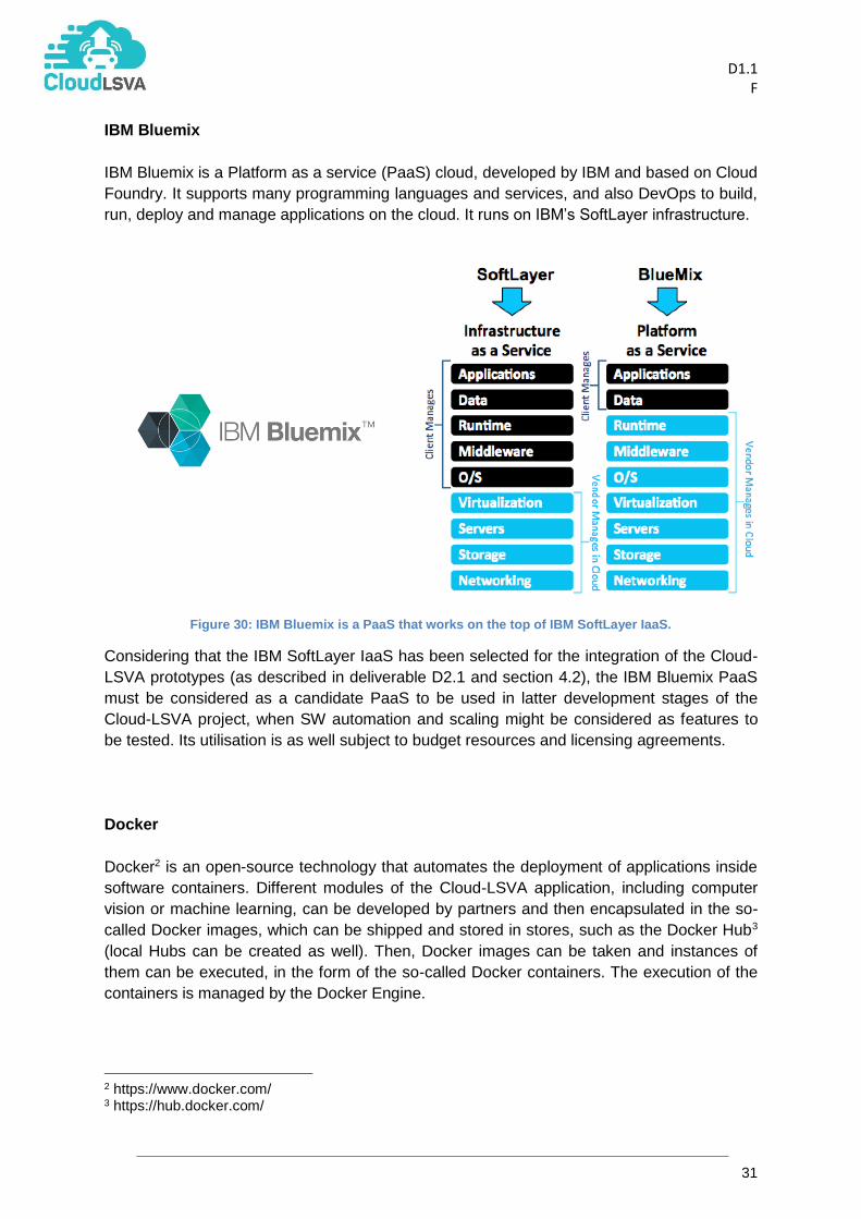
IBM Bluemix
IBM Bluemix is a Platform as a service (PaaS) cloud, developed by IBM and based on Cloud
Foundry. It supports many programming languages and services, and also DevOps to build,
run, deploy and manage applications on the cloud. It runs on IBM’s SoftLayer infrastructure.
Figure 30: IBM Bluemix is a PaaS that works on the top of IBM SoftLayer IaaS.
Considering that the IBM SoftLayer IaaS has been selected for the integration of the Cloud-
LSVA prototypes (as described in deliverable D2.1 and section 4.2), the IBM Bluemix PaaS
must be considered as a candidate PaaS to be used in latter development stages of the
Cloud-LSVA project, when SW automation and scaling might be considered as features to
be tested. Its utilisation is as well subject to budget resources and licensing agreements.
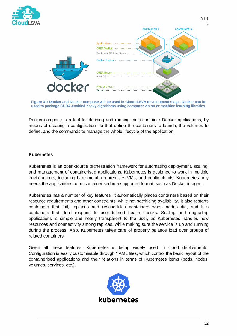
Docker
Docker2 is an open-source technology that automates the deployment of applications inside
software containers. Different modules of the Cloud-LSVA application, including computer
vision or machine learning, can be developed by partners and then encapsulated in the so-
called Docker images, which can be shipped and stored in stores, such as the Docker Hub3
(local Hubs can be created as well). Then, Docker images can be taken and instances of
them can be executed, in the form of the so-called Docker containers. The execution of the
containers is managed by the Docker Engine.
2 https://www.docker.com/ 3 https://hub.docker.com/
D1.1
F
32
Figure 31: Docker and Docker-compose will be used in Cloud-LSVA development stage. Docker can be used to package CUDA-enabled heavy algorithms using computer vision or machine learning libraries.
Docker-compose is a tool for defining and running multi-container Docker applications, by
means of creating a configuration file that define the containers to launch, the volumes to
define, and the commands to manage the whole lifecycle of the application.
Kubernetes
Kubernetes is an open-source orchestration framework for automating deployment, scaling,
and management of containerised applications. Kubernetes is designed to work in multiple
environments, including bare metal, on-premises VMs, and public clouds. Kubernetes only
needs the applications to be containerised in a supported format, such as Docker images.
Kubernetes has a number of key features. It automatically places containers based on their
resource requirements and other constraints, while not sacrificing availability. It also restarts
containers that fail, replaces and reschedules containers when nodes die, and kills
containers that don't respond to user-defined health checks. Scaling and upgrading
applications is simple and nearly transparent to the user, as Kubernetes handles new
resources and connectivity among replicas, while making sure the service is up and running
during the process. Also, Kubernetes takes care of properly balance load over groups of
related containers.
Given all these features, Kubernetes is being widely used in cloud deployments.
Configuration is easily customisable through YAML files, which control the basic layout of the
containerised applications and their relations in terms of Kubernetes items (pods, nodes,
volumes, services, etc.).

D1.1
F
33
Figure 32: Kubernetes: (left) cluster example; and (right) Kubernetes architecture where containerised applications run inside pods, alongside with related volumes. One of multiple pods run inside one node (VM).
4.1.3 Application layer Finally, a reference architecture for the Software Level is then defined based on this platform with core modules listed in Table 1, and list of exposed core services listed in Table 2. Figure 33 shows an illustrative diagram of the identified Cloud-LSVA engines (also referred to as “Modules” or “Managers”), with a separation between the back-end and front-end layers, the underlying infrastructure resources (compute, data, stores, etc.), and the core services exposed across the platform. This conceptual view ignores the type of technology to use, and the specific Platform and Infrastructure used.
Figure 33: Diagram of the reference architecture.

D1.1
F
34
In general terms, the Cloud-LSVA system is a cloud-based system that exposes a number of
functionalities related to the annotation of large volumes of data coming from sensorised
vehicles.
In basic terms, there are four main elements around the Cloud-LSVA system:
Data: in the form of video/sensor information recorded from equipped vehicles
Front-end: the (web) interface of the system to the human users of the platform,
which exposes services and functionalities to perform actions (e.g. annotation videos,
training models, etc.).
Back-end: the core SW engines that provide the underlying functionality of the
system (e.g. learning, deploying algorithms, storing data, formatting annotations,
etc.).
Cloud resources: the infrastructure that enables the functionalities, including
storage resources (NAS system), annotation databases (e.g. MongoDB), tools store
(i.e. Docker Registry), and computing resources (e.g. GPU-enabled servers).
There are three main users of Cloud-LSVA:
Annotators: operators that access Cloud-LSVA to perform annotation tasks through
a GUI, such as identifying objects in images, time lapse with recognised actions, etc.
Scientists: trained personnel expert in ADAS system and computer vision and/or
deep learning technologies, that use Cloud-LSVA to manage datasets, analyse and
train models, and to evaluate the performance of ADAS systems.
Uploaders: the content collected from sensorised vehicles must be uploaded to the
cloud-side storage for its analysis, and must be monitored and controlled by the
platform.
Intentionally, the Cloud-LSVA will offer a common GUI through a web application, which will
work as the front-end of the system. The implementation of this Web App Engine can be
tackled using a variety of technologies (Google App Engine, App Scale, Polymer, etc.). The
front-end provides the access to the different functionalities offered by the back-end.
The back-end of Cloud-LSVA is basically composed by the SW engines that provide the
functionality of the system, which relies on the HW systems where the Cloud-LSVA platform
is deployed (including the storage of raw content from sensors, and the computing clusters
where the SW is executed). The SW part is, therefore, composed of a number of modules, in
the form of web applications (e.g. Web Application Archives) which define functions and
REST interfaces for interoperability (details are provided in tables below and in section 4.3).
Cloud-LSVA can then be used to4:
to annotate spatio-temporal annotations on multiple synchronised video streams.
to launch automatic annotation processes on subsets of video footage.
to create a training set from a set of annotations.
to train machine learning models from created training sets.
to load existing annotations and perform operations (verify, correct, detail, etc.)
4 An extended and detailed list of annotation use cases is provided in deliverable “D3.4 Video Annotation Tools”, and updated use cases are continuously being created by the consortium during the development tasks, and will be reported at the corresponding prototype reports (D5.4 and D5.5).

D1.1
F
35
to upload new content into the storage repositories.
to evaluate the performance of a given algorithm against an annotated dataset.
To do so, the Cloud-LSVA application layer requires the implementation of the following
modules and preliminary list of exposed services:
Table 1: Main Cloud-LSVA modules.
Engine / Element
Description Tooling*
Analytics Engine Creates recipes about training models, generate training sets, execute detectors on datasets.
Returns updated models, training sets, annotations.
Communicates with Datasets manager to receive Data/Metadata
RTMaps
Viulib/OpenCV
Caffe/DIGITS/TensorFlow
Annotation Engine
Communicates with Datasets Manager to access Metadata
Creates/Updates/Merges annotations from different sources (e.g. automatic or manually generated).
Compares annotations to create evaluation reports
Viulib VCD
Viulib Evaluator
Dataset Engine Manage and browse the measurements datasets as well as fragments; datasets includes measurements, scene sets, training sets, …
RTMaps
MongoDB
Search Engine Execute short as well as long duration queries to the Cloud-LSVA system.
MongoDB
Elastic Search
Upload Engine Manage the upload and transformation of large datasets
RTMaps
SoftLayer Data Transfer Service
Web App Engine Provides GUI to users: annotation interface, training/engineer interface, app management interface
Handle authentification and security tokens
Polymer
HTML-5
emscripten
AppScale * Tooling: this is a list of preliminary selected technologies for the development of the identified module. However, this document only presents a reference architecture, i.e. a definition of the functionalities and the expected interfaces, while the specific implementation depends on technology usage (to be reported at prototype deliverables D5.3, D5.4 and D5.5).
Additionally, some of the engines and elements identified in Figure 33 directly relate to
existing technologies that the consortium (i.e. these modules need not to be implemented,
existing technologies already provide the required functionalities).

D1.1
F
36
Table 2: Additional engines and elements provided by existing technologies.
Engine / Element
Description Tooling*
Tools Engine Manage and deploy analytics tools on the
compute cluster.
Manage the Tool store
Docker
Tools Store Repository of tools available for their
execution Docker Registry
Pipeline Engine Orchestrates execution of tools Manage and monitor the compute cluster elastically.
Docker-compose Kubernetes
4.2 Cloud Infrastructure The infrastructure of the Cloud-LSVA platform is intended to facilitate the capture,
persistence, storage and simulation of very large video datasets in the cloud. Data can be in
the form of compressed or uncompressed multiple HD video streams and will be
accompanied by annotations (after processing). For the first phase, the aim is to work with a
video data set up to but not exceeding 20TB in size, the decision for subsequent phases will
be made at the end of the preceding one. The challenge is to provision a sufficient amount of
storage and computing power in a timely fashion to enable adequate storing and processing
of the data, while keeping within the budgetary constraints of the grant agreement.
From a high level, the platform can be built upon on either virtual or bare metal servers, with
many varying configurations available. The recommendation at this point is to build the
platform on bare metal servers, provisioning virtual machines from this base as required.
This will negate the potential security pitfalls of having a multi tenancy scenario, while also
centralising the effort for securing the platform, which is a key issue, considering that
elements of video footage that may contain personally identifiable information. (Obfuscation
cannot happen until after annotation as otherwise the algorithms would be rendered
useless).
An additional advantage for having a secure centralised storage and management location
for video data on the cloud is that the overhead of working towards an audit compliant
platform will be minimised. As each phase progresses the provisioned hardware can be
reassessed based on lessons learned and expected future requirements.
4.2.1 Physical specifications
At this phase in the project, there are still open questions as to which algorithms are going to
be used for annotation, what file types are going to be used for the video files, will video be
processed while compressed or decompressed and what database(s) will be required to sew
it all together. The answer to these questions will help shape what hardware is required and
when, so prepare for this, multiple options have been explored. In the initial set of
processing, the algorithms and subset of data are likely to be used are not expected to

D1.1
F
37
require GPU’s for processing. RTMaps is the high performance asynchronous platform that
will be used for development, and this can exploit natively the threading and prioritisation of
tasks across the available hardware. This is an extremely beneficial tool to the consortium as
High Performance Computing (HPC) resources, regardless of platform vendor, are delivered
with a premium. A number of the members of the consortium will be acquiring high end PCs
for use during the project, these are anticipated to contain high end graphics cards. The goal
is to utilise these to benchmark algorithms performance, so that a server with GPU
capabilities is only provisioned when necessary. The difference in cost of provisioning a Bare
Metal server without GPU and one with GPU capabilities is evident from the below table.
This table lists the monthly cost of a server with zero, one and two Graphics Processing
Units. This particular server configuration has only 4x1TB SATA drive attached, this can
scale to a maximum of 12x6TB SATA or 12x1.2TB SSD, each with their own per TB cost.
No GPU Single GPU Dual GPU
Server Dual Intel Xeon E5-2620 v3 (6 Cores, 2.40 GHz)
Dual Intel Xeon E5-2620 v3 (6 Cores, 2.40 GHz)
Dual Intel Xeon E5-2620 v3 (6 Cores, 2.40 GHz)
Disk 4TB SATA configured as 2TB RAID10
4TB SATA configured as 2TB RAID10
4TB SATA configured as 2TB RAID10
RAM 64 GB RAM 64 GB RAM 64 GB RAM
Graphics Processing Unit N/A
NVIDIA Tesla K80 Graphic Card
NVIDIA Tesla K80 Graphic Card
Secondary Graphics Processing Unit N/A N/A
NVIDIA Tesla K80 Graphic Card
Monthly cost per node $917.89 $1,575.93 $2,110.93
The proposed initial platform plans to have a RAID 5 array with over 30TB of disk space and
an optional hot spare. A RAID 5 setup allows for fast read times (annotation will be read
heavy), and also has the bonus that if a disk fails, the parity checksum on the remaining
drives will be sufficient to recalculate the data on another drive. The bare metal servers are
fitted with 3Ware 9550SX RAID controllers for SATA drives which can be configured for
maximum performance. The ~30TB of disk space would allow for a bare metal hypervisor to
access the 20TB video archive to be stored, and allow for multiple sandboxes to copy
various scenes or scenarios for annotation.
Data can be uploaded via public or private uplinks with speeds from 100Mbps up to 10Gbs,
but with such large uploads expected it would not be a recommendable action. Instead it
would be quicker and cheaper to send a compatible device containing the required data to
the data centre to be connected directly to their network to remotely control the data transfer,
(such a data transfer service is being offered free of charge to all SoftLayer customers).
If a type-1 hypervisor is not the way forward, there are a variety of Operating Systems that
can be installed on the bare metal server (type-2 hypervisors can be installed on top of the
OS). Such options will increase the overhead of running virtual machines, but will also give
the option for installing various Operating Systems off the shelf (e.g. CentOS, Windows
Server, Redhat, Ubuntu to name a few). A benefit of this approach is that there are also a
number of databases that can be provisioned this way, such as MongoDB, MySQL and MS
SQL Server.

D1.1
F
38
4.2.2 Interface description
The SoftLayer administrator will have a login to the SoftLayer Customer Portal, which will
give tabbed access to all of the established devices, storage, network, security and services
and also giving a portal to the support areas. From here it will also be possible to open a
terminal window to connect directly into any provisioned servers. There is also an
Application Programming Interface (API) with SoftLayer, which is the development interface
that gives developers and system administrator’s direct interaction with the backend system.
The functionality exposed by the API allows users to perform remote server management,
monitoring and the ability to retrieve information from SoftLayer's various systems. Generally
speaking, any commands that can be run from SoftLayer’s Customer Portal GUI, can also
be run via the API. There are a couple of options being considered for the high speed high
volume data transfer needs for the Cloud LSVA project, Warp speed Data Transfer (WDT)
an open source option, and IBM’s Aspera High-Speed File Transfer, a high-speed, robust
and reliable data transfer solution that is also flexible and scalable. Other open source
alternatives that have been considered were RSYNC (checksums at the block level) and
BBCP (checksums at file level), the latter of which would be better for the large media files
expected, it is also multi-stream so should have better throughput rates overall. Once a
server is up and running (virtual or otherwise) it will be able to be connected to via the usual
secure channels such as SSH. The goal for the project is not for the consortium to access
the cloud platform directly via the interfaces as mentioned above, rather to use the power of
RTMaps and iDEEP (Intempora) to act as the primary interface for accessing and
processing the video data.
4.3 Software Components
This section details the functionality and services provided by each of the SW components of
the Cloud-LSVA system, as identified in section 4.1.3.
4.3.1 Web front-end
This is the module that creates a web-based Graphic User Interface (GUI) from which users
can interact with the Cloud-LSVA platform.
As previously defined, different types of users are expected: (i) annotators, (ii)
engineers/scientists, and (iii) system managers. Therefore, different type of interfaces will be
presented according to the user credentials to enable role-specific functions.
A great level of detail about this module can be found in deliverable “D3.2 Initial User
Interface SW for Automatic and Collaborative Video Annotation”, which gathers the
developments reached with respect the GUI at month 10 of the project. Additionally, a report
on the integration of the Web front-end can be found in section 2.2.2 of deliverable “D5.3
Report on Cloud-LSVA prototype Alpha”.

D1.1
F
39
4.3.2 Annotation engine
The Annotation engine exposes services for reading, creating, updating and managing
annotations, in the form of Video Content Description (VCD) and Scene Content Description
(SCD) files or messages (see section 4.4.3).
For some services, the Annotation engine internally calls the Search engine to locate and
retrieve information from the annotation databases (e.g. getVCD).
In its simplest form, the annotation engine is only an interface to access the annotations in
the databases, but potentially, more functionality could be added to this module, such as
annotation merging, rating, automatic updating, etc.
Table 3: Annotation services.
Resource Method Arguments Description
getSCDList GET content: empty This service retrieves the registered list of SCD available at the raw data dataset.
addSCD POST Content: SCD file This service adds a SCD file to the list of available raw data dataset.
getSCD GET Content: SCD id This service retrieves SCD file corresponding to the given id.
getVCDList GET Content: SCD id This service retrieves the VCD file names corresponding to a certain SCD.
getVCD GET Content: SCD id, VCD id This service retrieves the VCD identified with a given VCD id inside the SCD.
updateVCD PUT Content: VCD, VCD id This service takes as input a given VCD content and integrates it into an existing VCD file.
deleteVCD GET Content: VCD id This service deletes a given VCD.
4.3.3 Dataset engine
The Dataset engine is the module that interfaces with the raw data datasets, i.e. the
recordings. In particular, video, Lidar and other sensor information is encapsulated into
RTMaps files (see section 4.5). Therefore, the Dataset engine will be implemented linked to
the RTMaps SDK, in order to access the data inside the RTMaps files and provide the
required services.

D1.1
F
40
It is expected that standard one-minute video (or sensor) clips are used as the atomic unit of
information inside the Cloud-LSVA system. Related services will be provided to extract such
one-minute clips from the larger RTMaps files. Those files will be temporarily stored and a
database of such existing files will be maintained by the Dataset engine.
The Dataset engine is also responsible to creating and managing training sets (in general,
collection of images), created from annotations and usable by the Analytics engine.
Table 4: Data engine services.
Resource Method Arguments Description
createVideoClip GET Content: SCD file, time frame
This service gets a petition to create/extract a video clip from a source raw data specified at SCD.
The output is the path to the location of the generated video file.
deleteVideoClip GET Content: video clip name This service deletes an existing temporary video clip file used for annotation.
getVideoClipList GET Content: empty This service returns the names of the temporary video clips files existing in the system (this is a list of video clips under annotation).
getTrainingSetList GET This service gets the existing list of stored training sets.
createTrainingSet POST Content: VCD This service creates a training set by means of cropping image patches from certain positions specified by the VCD.
4.3.4 Search engine The Search engine is the module that exposes services to find specific content inside the annotation
and raw data databases.
The annotation task starts with the use of the Search engine, in order to retrieve video content to
annotate. Queries can be administrative, i.e. related to metadata of the video, e.g. date, geolocation,
or type of sensor; or semantic, i.e. related to the content of the annotations, such as the presence of
specific type of objects in the image (e.g. “car”, “pedestrian”), or actions (e.g. “overtaking”).
In its most basic form, the Search engine is simply a database server, such as the MongoDB, that
itself exposes search services. The semantic analysis may require the implementation of specific
code or the integration of additional libraries for semantic reasoning over the annotations.

D1.1
F
41
Resource Method Arguments Description
getVideoClip GET Content: message This service finds a specific video file inside the database, and retrieves the path of a created video clip.
getAnnotation GET Content -
4.3.5 Analytics engine
The Analytics engine is a web application that exposes services related to the analysis of the
content of the images. In particular, two main groups of analytics are considered:
Video analytics tools: analytics related to the process of annotation of a video: e.g.
tracking, detecting objects, segmentation, etc.
Machine learning tools: analytics related to the generation of machine learning models,
training sets, evaluation reports, etc.
The Analytics engine, upon request of one of the provided services, identifies which
algorithms to execute, and gets in contact with the Tools engine to launch them, and receive
the result back.
The following list is a preliminary set of services that the Analytics engine may expose. The
details about the arguments and responses are yet to be defined:
Table 5: Analytics services for video annotation tools.
Resource Method Arguments Description
trackObject GET content: JSON message containing a bounding box and, frame number, and a video identifier.
This service launches visual tracking algorithms to track the given object in the sequence. The result is a VCD annotation with all the bounding boxes of the object along the sequence.
detectObject GET content: JSON message containing a video identifier and additional time intervals.
Content: name of object class to detect (e.g. “Car”, “Pedestrian”, “Lanes”).
This service launches a detector of the specified objects in the given video, by using detection-by-classification tools, or equivalent. The detector is selected from those available and using the models at the models database.
segmentImage GET content: JSON message containing a frame number and a video id.
This service launches a segmentation mechanism that creates a pixel-wise masks that associates labels to pixels (e.g. “road”, “tree”, “sky”, “pedestrian”)

D1.1
F
42
Table 6: Analytics services for machine learning tools.
Resource Method Arguments Description
train GET content: JSON message containing the id of a training set, and the name and parameters of a trainer.
This service launches a training mechanisms that reads the provided training set and generates a trained model as output, storing it into the models database.
test GET content: JSON message containing the id of a model and a testing set.
This service launches a testing mechanism that executes a given model against a certain testing dataset, in order to collect performance metrics.
getModelsList GET Content: This service returns the list of available models for detection.
addModel POST Content: This service uploads a certain trained model in the models database.
4.3.6 Upload engine
There are two main mechanisms to upload content into the Cloud-LSVA storages, one per
application domain:
ADAS: bulk direct transfer of content from NAS system into the storage device at
infrastructure level (typically connecting a USB 3.0 connected from a NAS system used
to record data in the vehicle into the NAS system of the Cloud-LSVA infrastructure). This
type of transfer is required to upload massive amounts of data from sensorised vehicles
(e.g. 20 TB from a 1-week recording session with a equipped vehicle).
Digital cartography: upload of small set of data (in the form of messages) from mobile
devices. The upload is achieved via exposing an upload service. The content of the
message can be the output of an on-board device that generates some metadata and a
picture of a certain situation of the road, e.g. a detected traffic sign.
In the first case, new recordings will be automatically detected by a daemon service that will
generate a Scene Content Description (SCD) file/entry describing the administrative
information of the recording (e.g. calibration file name, date, location, vehicle, etc.). The SCD
file will be stored in the annotation database.
In the second case, the exposed service will automatically handle the incoming information
and add it into the corresponding database.
4.3.7 Tools engine
In its most basic form, the tools engine is simply an application that can execute the
instantiation of containerised applications which may reside in a registry of available tools.

D1.1
F
43
The most straightforward technology to use is Docker, where tool is then translated to
container, and the registry is the Docker Registry.
At development stage, the Docker engine will be used to launch container applications,
mainly from the Analytics engine. The Docker Registry will be managed manually to update
the available tools.
Eventually, the Cloud-LSVA might provide an additional layer that exposes services to users
to upload new containers to the Store, via the front-end application.
4.3.8 Pipeline engine
The pipeline engine is a middleware engine that determines which tools need to be
executed, using what underlying resources, and in which order. As described in section
4.1.3, this engine can be implemented, during the development of the project, in the form of
3rd party SW platforms.
In particular, Kubernetes seems to be a good choice for its ability to manage and orchestrate
containerised applications (see section 4.1.2).
4.4 Communication and Data Format
4.4.1 Physical specifications
The TomTom services will be deployed as individual “Micro” Services in a lightweight
deployment container. (Docker) By using individual service endpoints behind load balancers
we ensure that elasticity is part of the core cloud architecture.
4.4.2 Interface description
The TomTom services operate as an isolated services and will use independent tooling. At
interface level the service will comply to the consortium eco system and use as much as
possible the common resources and interfaces.
In addition, the TomTom services will offer an interface for:
speed sign recognition
an endpoint to download the latest Lane Map update
All interfaces will be exposed as REST interface over http(s) using protobuf as binary
encoding format. When high-speed near real-time communication is needed a websocket
based solution will be offered in parallel based on the same protobuf messages.
Detailed technical interface descriptions will be produced as the project goes into it different
phases.

D1.1
F
44
4.4.3 Annotation format
An in-depth discussion about annotation data model, and annotation file formats is provided
in deliverable “D3.1 Import/export interfaces and Annotation data model and storage
specification”. In this section, one of the options for the annotation data model (the Viulib
Video Content Description, VCD, www.viulib.org) is described according to the defined
requirements of section 3.4.
Although existing description languages also include general purpose semantic description
standards such as MPEG-7, or dedicated schemes like ViPER (Visual Information
Processing for Enhanced Retrieval), they are way too vast and general to handle specific
video content description (MPEG-7), or old and difficult to use and extend (ViPER). VCD is
an annotation data model specially devised to describe content of image sequences, in the
form of spatial, temporal, or spatio-temporal entities. The annotation of spatial entities is
abstract to include any possible Object data type, such as points, lines, polygons, binary
masks, or generic arrays of numbers. Semantic actions occurring in the videos can be easily
described as Contexts, or Events, reaching any desired level of annotation complexity. The
VCD is designed to support connection with ontologies, through the definition of Relations.
All the elements can be defined and manipulated in both offline (batch processing) and
online (updated sequentially) modes. The VCD C++ API provides a number of tools to
perform operations on the annotations, such as create, update/modify, delete, find, etc.
Annotations can be stored as XML files, but also messaged as JSON strings. It is integrated
in the latest version of Vicomtech’s Viulib libraries (www.viulib.org). Additional
implementations include C++ classes that compare two different VCD files and create
evaluation reports (e.g. comparison with ground truth).
The work reported in this section is related to the extension of the extension of the VCD
concept into the Scene Content Description (SCD) format, and its actual implementation.
Currently, the implementation of SCD consists on a C++ module, integrated in Viulib5. This
implementation allows to create, load, manage and update SCD and VCD content. The
interfaces so far implemented include XML and JSON parsing and marshaling, in both
element-wise and frame-wise modes.
The SCD is, therefore, a data annotation model and a reference implementation that
responds to the following requirements:
Single scene annotations of multiple sensors (focused but not limited to video)
Annotation of multi-dimensional Objects (space and time)
Description of Events/Actions
Description of function-related annotations
Connection to ontologies to enable semantic reasoning
Good storage/streaming trade-off
Online and batch processing modes
Efficient API to integrate into embedded systems (C++ interface)
Represent training sets for machine learning
Convertible into other description languages 5 http://www.vicomtech.org/viulib

D1.1
F
45
Neither existing DSL nor standard covers these requirements in an efficient and simple way.
As Figure 34 depicts, the SCD concept covers scenarios where a certain scene is being
recorded with one or more sensors, and annotations corresponding to the sensors are
produced. The annotations for each individual sensor are stored in a specific VCD. The SCD
contains, additionally, other structures that help finding the raw data corresponding to the
annotations (e.g. the names of the video files), and interrelationships between the sensors
(e.g. relative position and rotation, or inter-sensor annotation correspondences).
Figure 34: Scene Content Description is a data annotation model that can host annotations from multiple, varied sensors.
Each VCD can contain a variety of annotations, including Objects, Actions, or Relations, as
illustrated by Figure 35.

D1.1
F
46
Figure 35: Elements of the VCD
The internal structure of the VCD can be of twofold: element-wise or frame-wise.
Element-wise: information is stored in blocks. It is suitable for batch processing, and the
atomic units are Objects, Events, etc.
Frame-wise: information is stored sequentially. It is best suited for online annotation and
message transmission. The atomic unit is Frame.
Figure 36: Element-wise and frame-wise internal structure of VCD.
The VCD is also able to store content with semantic load, in the form of Action, Events and
Relations (as depicted in 10). A Relation contains a description of the link between different
elements of the VCD such as Objects or Actions. The type of Relation can be a concept of a
given ontology, thus enabling further semantic reasoning over the VCD content.
Figure 37: The type file of the VCD Relation is in this example a concept from an ontology.
The annotations across VCDs is managed via the VCD Matrix, which defines the correspondences between elements in different VCDs:

D1.1
F
47
Figure 38: Annotations across different VCDs, through the VCD Matrix.
Examples and reports on preliminary integration of this annotation format into the Cloud-
LSVA engines is provided in section 2.2.4 of deliverable “D5.3 Report on Cloud-LSVA
prototype Alpha”.
4.5 Scene Recording Module Both in ADAS and Cartography generation use cases, an in-car data recorded will have to
be designed accordingly to the requirements and will have to cope with the vehicle sensors
setup.
The requirements in terms of performance and logging bandwidth is very different between
the two uses cases:
The ADAS use case will require logging of very high bandwidth sensor data streams
such as several HD video streams from multiple cameras while such streams are not
supposed to be altered by compression for instance as they will be used later on for
image processing algorithms execution, evaluation, benchmarking, and potentially
statistical proof of correct operation in an ISO 26262 certification process. As an
overview, the amount of sensors data to record can reasonably be higher than 1
GB/s (10 Gb/s). This means 4 TB/h.
The Cartography generation will not be as demanding however it integrates the
requirement to be able to stream data to the Cloud server in near real-time via mobile
communication networks. It would require a high-accuracy/high frequency positioning
system, potentially lower frame rate video captures, point-cloud acquisition for 3D
information, etc.
4.5.1 Recorder capabilities
The recorder will be based on a PC to which all sensors will be connected via various
interfaces (Ethernet, USB 3.0, CAN & FlexRay adapters, etc.). It must have the capability to
associate an accurate timestamp to each and every data sample acquired from the various
sensors. Such timestamps have to refer to the same timebase, most likely the GPS time.
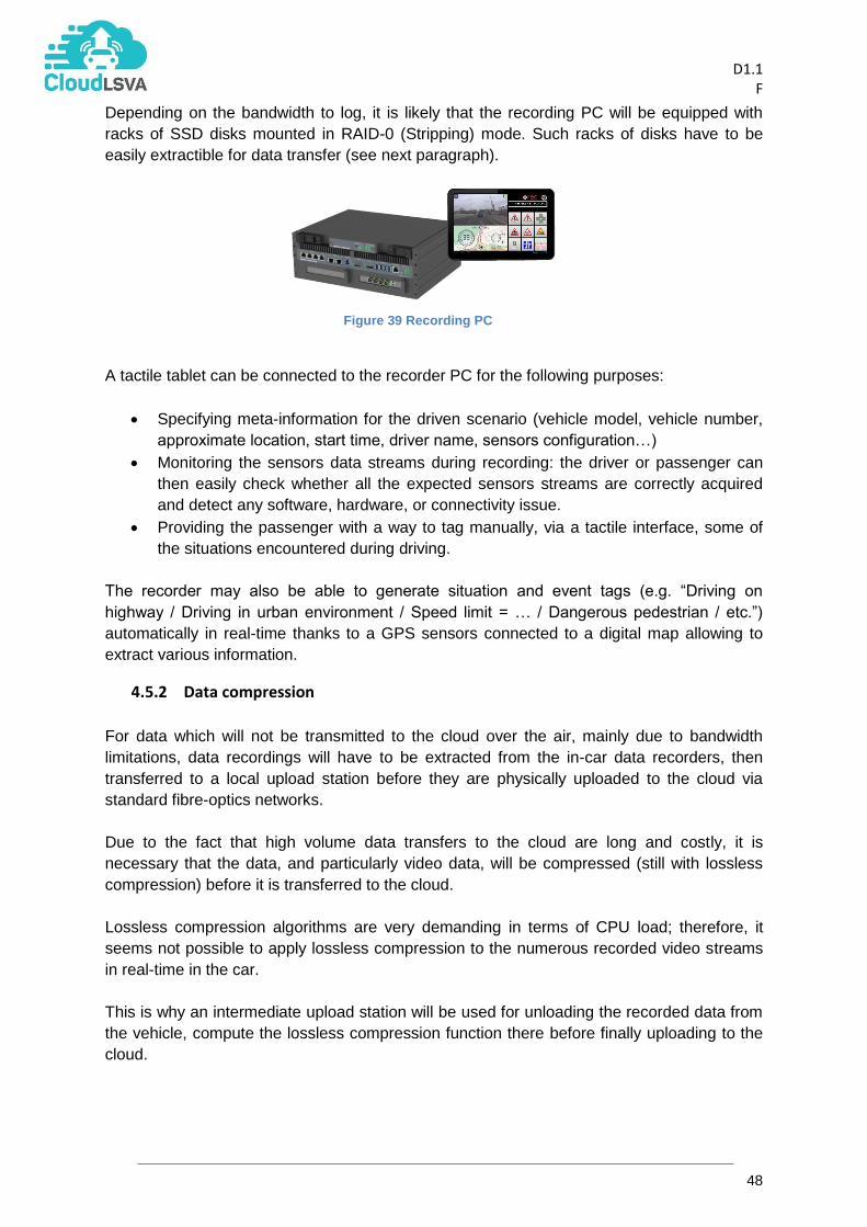
D1.1
F
48
Depending on the bandwidth to log, it is likely that the recording PC will be equipped with
racks of SSD disks mounted in RAID-0 (Stripping) mode. Such racks of disks have to be
easily extractible for data transfer (see next paragraph).
A tactile tablet can be connected to the recorder PC for the following purposes:
Specifying meta-information for the driven scenario (vehicle model, vehicle number,
approximate location, start time, driver name, sensors configuration…)
Monitoring the sensors data streams during recording: the driver or passenger can
then easily check whether all the expected sensors streams are correctly acquired
and detect any software, hardware, or connectivity issue.
Providing the passenger with a way to tag manually, via a tactile interface, some of
the situations encountered during driving.
The recorder may also be able to generate situation and event tags (e.g. “Driving on
highway / Driving in urban environment / Speed limit = … / Dangerous pedestrian / etc.”)
automatically in real-time thanks to a GPS sensors connected to a digital map allowing to
extract various information.
4.5.2 Data compression
For data which will not be transmitted to the cloud over the air, mainly due to bandwidth
limitations, data recordings will have to be extracted from the in-car data recorders, then
transferred to a local upload station before they are physically uploaded to the cloud via
standard fibre-optics networks.
Due to the fact that high volume data transfers to the cloud are long and costly, it is
necessary that the data, and particularly video data, will be compressed (still with lossless
compression) before it is transferred to the cloud.
Lossless compression algorithms are very demanding in terms of CPU load; therefore, it
seems not possible to apply lossless compression to the numerous recorded video streams
in real-time in the car.
This is why an intermediate upload station will be used for unloading the recorded data from
the vehicle, compute the lossless compression function there before finally uploading to the
cloud.
Figure 39 Recording PC

D1.1
F
49
The data recorder itself has to provide the capability to accurately timestamp all the sensor.
4.5.3 Physical specification for sensors
ADAS use case
The recorder will be equipped with the following sensors:
Sensor type Number of sensors
Interface Frame rate / Resolution
Estimated bandwidth
Cameras 4 to 6 USB 3.0 Or GigaEthernet
Up to 60 Hz / 1280 x 1024
100MB/s per camera
Velodyne laser scanner
1 GigaEthernet 15 Hz, 64 layers
3 MB/s
High accuracy INS (GPS + IMU)
1 Ethernet 100 Hz 1 MB/s
FlexRay interface
1 PCIe or USB ? ?
Upload Station
Data Acquisition Vehicle
Cloud
Figure 40 Data acquisition and upload process
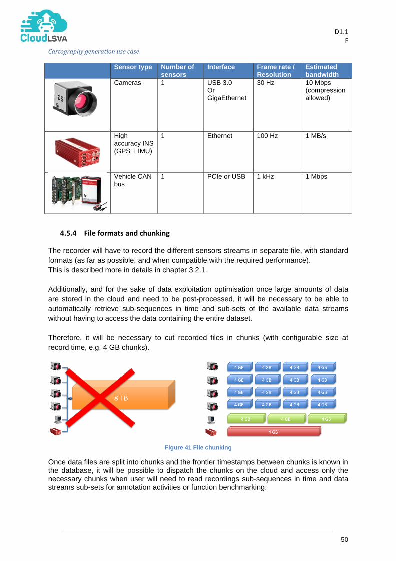
D1.1
F
50
Cartography generation use case
Sensor type Number of sensors
Interface Frame rate / Resolution
Estimated bandwidth
Cameras 1 USB 3.0 Or GigaEthernet
30 Hz 10 Mbps (compression allowed)
High accuracy INS (GPS + IMU)
1 Ethernet 100 Hz 1 MB/s
Vehicle CAN bus
1 PCIe or USB 1 kHz 1 Mbps
4.5.4 File formats and chunking The recorder will have to record the different sensors streams in separate file, with standard
formats (as far as possible, and when compatible with the required performance).
This is described more in details in chapter 3.2.1.
Additionally, and for the sake of data exploitation optimisation once large amounts of data
are stored in the cloud and need to be post-processed, it will be necessary to be able to
automatically retrieve sub-sequences in time and sub-sets of the available data streams
without having to access the data containing the entire dataset.
Therefore, it will be necessary to cut recorded files in chunks (with configurable size at
record time, e.g. 4 GB chunks).
Figure 41 File chunking
Once data files are split into chunks and the frontier timestamps between chunks is known in the database, it will be possible to dispatch the chunks on the cloud and access only the necessary chunks when user will need to read recordings sub-sequences in time and data streams sub-sets for annotation activities or function benchmarking.
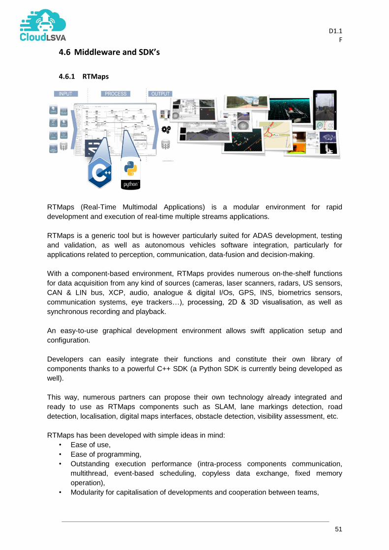
D1.1
F
51
4.6 Middleware and SDK’s
4.6.1 RTMaps
RTMaps (Real-Time Multimodal Applications) is a modular environment for rapid
development and execution of real-time multiple streams applications.
RTMaps is a generic tool but is however particularly suited for ADAS development, testing
and validation, as well as autonomous vehicles software integration, particularly for
applications related to perception, communication, data-fusion and decision-making.
With a component-based environment, RTMaps provides numerous on-the-shelf functions
for data acquisition from any kind of sources (cameras, laser scanners, radars, US sensors,
CAN & LIN bus, XCP, audio, analogue & digital I/Os, GPS, INS, biometrics sensors,
communication systems, eye trackers…), processing, 2D & 3D visualisation, as well as
synchronous recording and playback.
An easy-to-use graphical development environment allows swift application setup and
configuration.
Developers can easily integrate their functions and constitute their own library of
components thanks to a powerful C++ SDK (a Python SDK is currently being developed as
well).
This way, numerous partners can propose their own technology already integrated and
ready to use as RTMaps components such as SLAM, lane markings detection, road
detection, localisation, digital maps interfaces, obstacle detection, visibility assessment, etc.
RTMaps has been developed with simple ideas in mind:
• Ease of use,
• Ease of programming,
• Outstanding execution performance (intra-process components communication,
multithread, event-based scheduling, copyless data exchange, fixed memory
operation),
• Modularity for capitalisation of developments and cooperation between teams,

D1.1
F
52
• Interoperability with other environments (such as Matlab® & Simulink®, ROS,
Qt/QML, various simulators…)
• Scalability (lightweight, portable and distributable runtime engine)
RTMaps can as well be controlled programmatically by third-party software thanks to a
control API. It can then be used in cars but also take part in automated processing tasks in
the cloud.
4.6.2 Computer vision and Machine learning SDKs The ability of Cloud-LSVA to annotate partly relies on the automatic computation of models
from labeled data, and to identify instances of Objects and Events on video. For that
purpose, computer vision and machine learning algorithms will be implemented. The vision-
related SDKs to be used are enlisted as follows:
Name Description License
OpenCV OpenCV (Open Source Computer Vision Library) is an open source computer vision and machine learning software library.
BSD
Viulib® Viulib (Vision and Image Utility Library) is a set of precompiled libraries that simplifies the building of complex computer vision and machine learning solutions, specially focused on sectors such as ADAS.
Proprietary (Vicomtech-IK4)
Caffe Caffe is a deep learning framework made with expression, speed, and modularity in mind.
BSD 2-Clause
DLib Dlib is a modern C++ toolkit containing machine learning algorithms and tools for creating complex software in C++ to solve real world problems.
Boost Software License.

D1.1
F
53
4.6.3 RoadDNA The ‘real-time map’ is stored on the navigation device and kept up-to-date by incremental
update services from the cloud.
The ‘Lane Map’ is a standard map also used for road-level navigation systems. It is based
on NDS (Navigation Data Standard). NDS is a runtime format that is scalable to enable
incremental updates to the NDS map (regional, tile or attribute patch). For the lane
navigation research the NDS map is extended with a layer containing detailed-lane-
information linked to road segments in the map that is required for lane-navigation- and
highly-automated-driving systems.
Next to that, ‘RoadDNA’ maps are made available that are created from point cloud
information and that can be used to position the car within its local 3D environment
correlating the camera images with the point cloud information from the RoadDNA maps.
Figure 42: RoadDNA example.
D1.1
F
54
5. Ontology definition
This section defines the term ontology in the context of the Cloud-LSVA project and its
applications, lays out the initial steps for creating or assembling the ontology or ontologies
and provides a brief overview of relevant technologies and state of the art work in this area.
5.1 Definition Somewhat ironically the term “ontology” has many varying definitions. For the purpose of this
project, we follow Tom Gruber’s well-known definition that ontology is “a formal specification
of a shared conceptualisation”6. Hence we define ontology within Cloud-LSVA as: a formal
description of the vocabulary, concepts (objects, actions, properties) and their inter-
relations (scenarios) in the context of annotating, indexing and retrieving multimedia
data (principally video) in the domain of instrumented test vehicles. The ontology
document does not itself contain data (recordings, instances, etc.) but is the abstraction of
what terms, objects and situations are possible in this particular domain.
Where possible we will re-use existing standard ontologies or controlled vocabularies from
recognised industry bodies or other academic research. These external ontologies or
vocabularies will be linked to from a core Cloud-LSVA ontology where needed. The term
Cloud-LSVA ontology will encompass both the core ontology iteratively created by the
project and the linked external ontologies or standards.
5.2 Applications There are three main uses for the Cloud-LSVA ontology. First, to define as far as possible
the necessary objects and events to be annotated (either manually or semi-automatically) in
the available video data. Second, to provide a controlled vocabulary to accurately define
scenarios for search and retrieval from annotated and indexed video data. Third, to enhance
machine learning techniques for improving annotation accuracy. For example, by defining
two concepts as mutually exclusive – a vehicle cannot be both a plane and a car at the same
time – this can be used to refine or constrain a trained machine annotation algorithm. Initially
development for the first two uses will be prioritised.
To illustrate how the Cloud-LSVA ontology could be used, consider the use cases outlined in
section 2. For example, the ontology could define concepts such as vehicle and person, their
potential spatial relationships to each other (near-side, far-side), actions (braking,
accelerating, walking) and properties (large, child, truck, parked). The annotation tools would
use these terms to label test video, either manually or semi-automatically. This ensures
consistency across different environments and can assist reuse in different scenarios or
locations (e.g., sidewalk == footpath) as well as increasing search options. For instance, a
video specifically labelled truck is also relevant when looking for more general examples of
vehicles and can be discovered if the ontology defines “truck” as a specific type of “vehicle”
(a sub-class). A query can then be built using the vocabulary and relationships to define the
scenarios of interest and retrieve relevant video examples from the very large video dataset.
6 T. R. Gruber. “A Translation Approach to Portable Ontology Specifications.” In Knowledge Acquisition, volume 5(2), pp. 199–
220, 1992.

D1.1
F
55
5.3 Technology and related work A common definition language for ontologies is the Web Ontology Language7 or OWL
developed by the World Wide Web Consortium (W3C). This language is based on the
concept of a triple, Subject-Predicate-Object, as encapsulated in the Resource Description
Framework (RDF). This simple construct forms the basis of the aims for indexable and
programmable content from the semantic web movement. OWL is a useful format for
defining ontologies with available tool support for writing, reasoning over (inference and
deduction) and other programming libraries (interface generation, RDF-based data stores,
etc.).
5.4 Example ontology An example ontology has been designed to describe the scenarios that involve scene
understanding and recognising. Every scene has several factors in common among which
are include actors, actions, a time interval and a scenario.
The main goal of every ontology is to offer a clear and quick view of a scheme, so it has to
be as simple as possible and yet be composed of each element that needs to be describe in
order to give a descriptive solution to a problem, in this case, every possible case involving
scene understanding and recognising.
There are several languages recognised in the semantic field, that describe an ontology, we
have used OWL as it is the most known and used nowadays. Each of this languages follows
some semantic rules so that every ontology can be read and interpreted correctly by every
user, for example, every element that needs to be added in the ontology are known as
classes. In our ontology the main classes that we have added are:
Object:
Static Object: Lane, Sidewalk. Every object that is involved in an action without
performing it.
Dynamic Object: Car, Person. Every object that performs the action.
Action: Person crossing, Lane changing. Every action performed by a dynamic object
in a static object.
Context: Rainy or sunny day. Data that might be relevant to describe the scene.
Time Interval: Frame start, frame end. Time range (in video processing the time
refers to a frame) in which the action has taken place.
Some classes need to be related to another classes, like Objects and Actions: a static object
(Person) performs an action (Person Crossing) in a static object (Sidewalk). These relations
are known in semantic languages as Object Properties. In our ontology we have added:
Has participants: An action “has participants” Actors (Objects)
Has time Interval: An action “has time interval” Time range.
Is container of: A context “is container” of Actions and Objects
These Object properties have inverse, such as, a Person “is participant of” an action, etc.
7 W3C, OWL 2 Web Ontology Language Document Overview (Second Edition), https://www.w3.org/TR/owl2-overview/

D1.1
F
56
Figure 43: Diagram of the ontology created with the VCD elements.
5.5 Next steps
In accordance with key principles of ontology development [5], the Cloud-LSVA ontology will
be iteratively refined throughout the cycles of the project based on input from both end-users
and developers. The results at each stage should support the required use cases but also be
extensible for future variations of the scenarios where feasible. The immediate next steps for
development are listed below:
1. Assemble overview of existing standards and ontologies relevant to the Cloud-LSVA
scenarios.
2. Create core ontology framework of the main concepts, inheriting or referencing
existing standards where possible.
3. Reformat relevant and required terms from standards in a machine processable
format (e.g., OWL) where necessary.
4. Collaboratively define the standards and formats for video annotations in agreement
with the requirements for annotation, software implementation and system
integration.

D1.1
F
57
6. References
[1] Kooij, J. F. P., Schneider, N., Gavrila, D. M. (2014). Analysis of pedestrian dynamics from a vehicle perspective. In Proc. IEEE Intelligent Vehicle Symposium (IV), June 8-11, 2014, Dearborn, Michigan, USA, pp. 1445-1450.
[2] Ulbrich, S., Menzel, T., Reschka, A., Schuldt, F., Maurer, M. (2015). Defining and
Substantiating the Terms Scene, Situation, and Scenario for Automated Driving. In 2015 IEEE 18th International Conference on Intelligent Transportation Systems (pp. 982–988).
[3] Hülsen, M., Zöllner, J. M., Weiss, C. (2011). Traffic intersection situation description ontology
for advanced driver assistance. Proceedings of IEEE Intelligent Vehicles Symposium (pp.993–999).
[4] Feld, M., Müller, C. (2011). The automotive ontology. In Proceedings of the 3rd International
Conference on Automotive User Interfaces and Interactive Vehicular Applications - AutomotiveUI ’11 (p. 79). New York.
[5] Gruber, T. R. (1995). Toward principles for the design of ontologies used for knowledge sharing? International Journal of Human-Computer Studies, 43(5-6), 907–928.