D-Link AirPlus Xtreme G TM VDI-624 - Verizon Basics ... WLAN LED A solid light indicates that the...
91
High-Speed 2.4 GHz Manual Building Networks for People Wireless Router D-Link AirPlus Xtreme G VDI-624 VDI-624 VDI-624 VDI-624 VDI-624 TM Version 2.43
Transcript of D-Link AirPlus Xtreme G TM VDI-624 - Verizon Basics ... WLAN LED A solid light indicates that the...
High-Speed 2.4 GHz
Manual
Building Networks for People
Wireless Router
D-Link AirPlus Xtreme GVDI-624VDI-624VDI-624VDI-624VDI-624
TM
Version 2.43
2
Contents
Package Contents ................................................................................3
Introduction............................................................................................4
Wireless Basics ....................................................................................8
Getting Started .................................................................................... 11
Using the Configuration Menu..............................................................12
Networking Basics ..............................................................................39
Troubleshooting...................................................................................54
Technical Specifications ......................................................................61
Frequently Asked Questions ................................................................64
Warranty..............................................................................................88
3
Internet Explorer Version 6.0 or Netscape NavigatorVersion 6.0 and Above
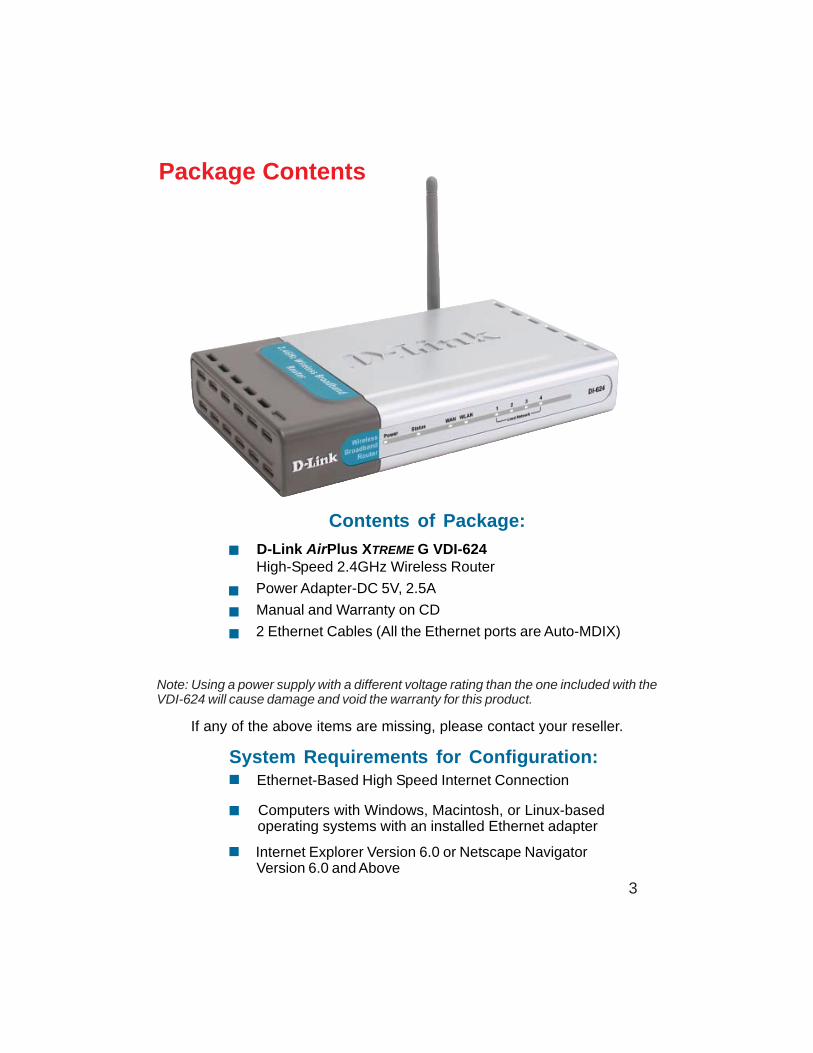
Contents of Package:
D-Link AirPlus XTREME G VDI-624 High-Speed 2.4GHz Wireless Router
Power Adapter-DC 5V, 2.5A
Manual and Warranty on CD
2 Ethernet Cables (All the Ethernet ports are Auto-MDIX)
Computers with Windows, Macintosh, or Linux-based operating systems with an installed Ethernet adapter
Package Contents
Note: Using a power supply with a different voltage rating than the one included with theVDI-624 will cause damage and void the warranty for this product.
If any of the above items are missing, please contact your reseller.
System Requirements for Configuration: Ethernet-Based High Speed Internet Connection
4
IntroductionThe D-Link AirPlus Xtreme G VDI-624 High-Speed Wireless Router is an 802.11g high-performance, wireless router that supports high-speed wireless networking at home, atwork or in public places.
Unlike most routers, the VDI-624 provides data transfers at up to 108 Mbps (comparedto the standard 54 Mbps) when used with other D-Link AirPlus Xtreme G products. The802.11g standard is backwards compatible with 802.11b products. This means that youdo not need to change your entire network to maintain connectivity. You may sacrificesome of 802.11g’s speed when you mix 802.11b and 802.11g devices, but you will notlose the ability to communicate when you incorporate the 802.11g standard into your802.11b network. You may choose to slowly change your network by gradually replacingthe 802.11b devices with 802.11g devices .
In addition to offering faster data transfer speeds when used with other 802.11g products,the VDI-624 has the newest, strongest, most advanced security features available today.When used with other 802.11g WPA (WiFi Protected Access) and 802.1x compatibleproducts in a network with a RADIUS server, the security features include:
WPA: Wi-Fi Protected Access authorizes and identifies users based on a secret keythat changes automatically at a regular interval. WPA uses TKIP (TemporalKey Integrity Protocol) to change the temporal key every 10,000 packets (apacket is a kind of message transmitted over a network.) This insures muchgreater security than the standard WEP security. (By contrast, the older WEPencryption required the keys to be changed manually.)
802.1x: Authentication is a first line of defense against intrusion. In the Authenticationprocess the server verifies the identity of the client attempting to connect to thenetwork. Unfamiliar clients would be denied access.
For home users that will not incorporate a RADIUS server in their network, the securityfor the VDI-624, used in conjunction with other 802.11g products, will still be muchstronger than ever before. Utilizing the Pre Shared Key mode of WPA, the VDI-624 willobtain a new security key every time it connects to the 802.11g network. You only needto input your encryption information once in the configuration menu. No longer will youhave to manually input a new WEP key frequently to ensure security, with the VDI-624,you will automatically receive a new key every time you connect, vastly increasing thesafety of your communications.
5
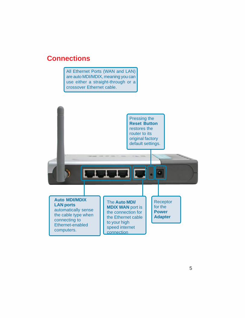
Connections
All Ethernet Ports (WAN and LAN)are auto MDI/MDIX, meaning you canuse either a straight-through or acrossover Ethernet cable.
The Auto MDI/MDIX WAN port isthe connection forthe Ethernet cableto your highspeed internetconnection
Auto MDI/MDIXLAN portsautomatically sensethe cable type whenconnecting toEthernet-enabledcomputers.
Receptorfor thePowerAdapter
Pressing theReset Buttonrestores therouter to itsoriginal factorydefault settings.
6
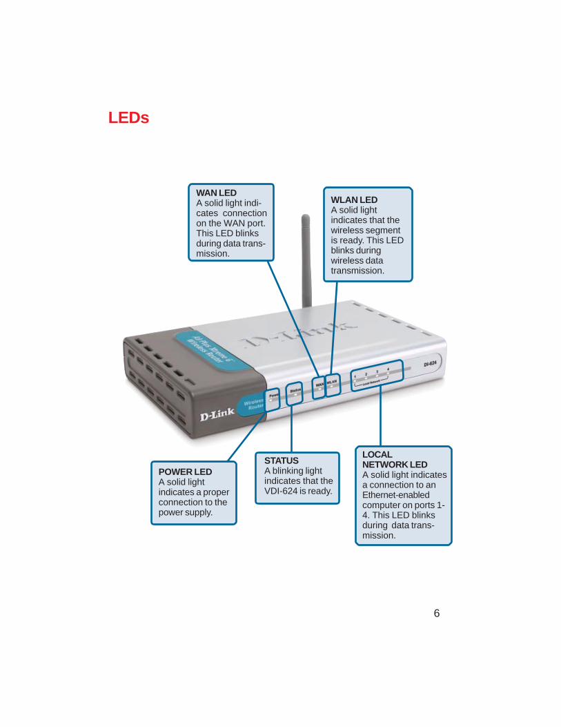
LEDs
WLAN LEDA solid lightindicates that thewireless segmentis ready. This LEDblinks duringwireless datatransmission.
POWER LEDA solid lightindicates a properconnection to thepower supply.
STATUSA blinking lightindicates that theVDI-624 is ready.
WAN LEDA solid light indi-cates connectionon the WAN port.This LED blinksduring data trans-mission.
LOCALNETWORK LEDA solid light indicatesa connection to anEthernet-enabledcomputer on ports 1-4. This LED blinksduring data trans-mission.
7
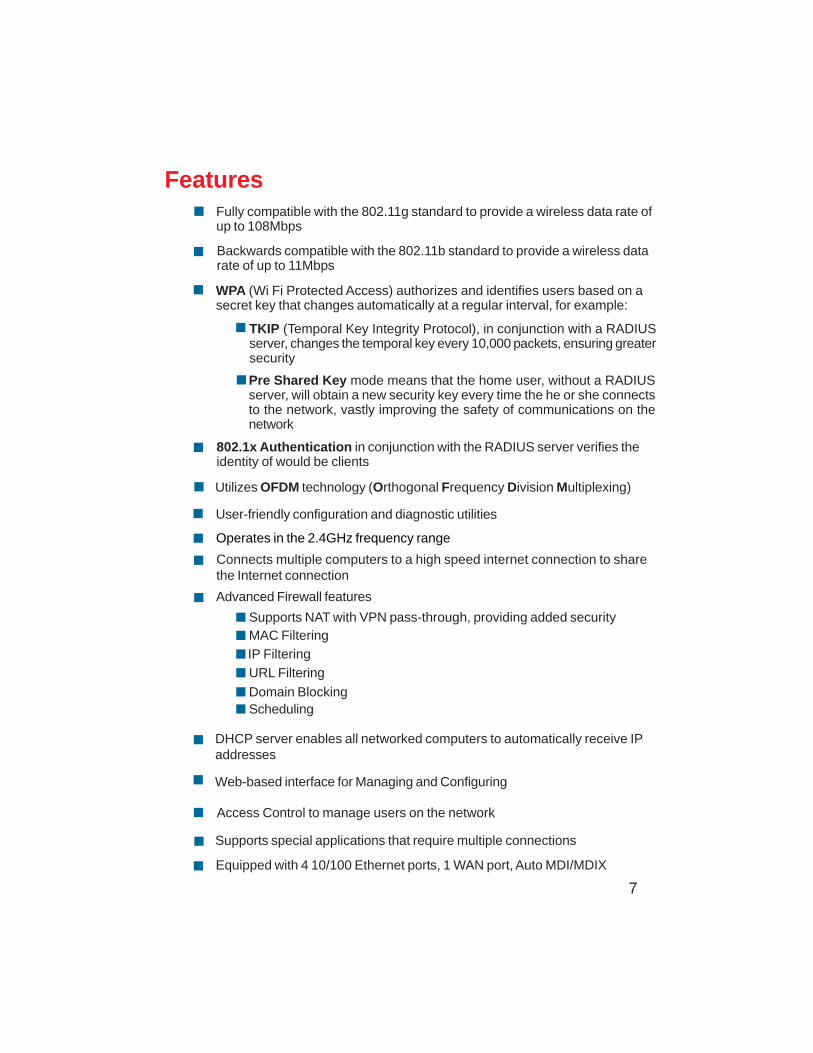
Features
WPA (Wi Fi Protected Access) authorizes and identifies users based on asecret key that changes automatically at a regular interval, for example:
802.1x Authentication in conjunction with the RADIUS server verifies theidentity of would be clients
TKIP (Temporal Key Integrity Protocol), in conjunction with a RADIUSserver, changes the temporal key every 10,000 packets, ensuring greatersecurity
Pre Shared Key mode means that the home user, without a RADIUSserver, will obtain a new security key every time the he or she connectsto the network, vastly improving the safety of communications on thenetwork
Backwards compatible with the 802.11b standard to provide a wireless datarate of up to 11Mbps
Fully compatible with the 802.11g standard to provide a wireless data rate ofup to 108Mbps
Utilizes OFDM technology (Orthogonal Frequency Division Multiplexing)
User-friendly configuration and diagnostic utilities
Operates in the 2.4GHz frequency range
Connects multiple computers to a high speed internet connection to sharethe Internet connection
IP Filtering
Advanced Firewall features
DHCP server enables all networked computers to automatically receive IPaddresses
Web-based interface for Managing and Configuring
Access Control to manage users on the network
Supports special applications that require multiple connections
Equipped with 4 10/100 Ethernet ports, 1 WAN port, Auto MDI/MDIX
URL Filtering
Domain BlockingScheduling
Supports NAT with VPN pass-through, providing added securityMAC Filtering
8
Wireless Basics
D-Link wireless products are based on industry standards to provide easy-to-use andcompatible high-speed wireless connectivity within your home, business or public accesswireless networks. D-Link wireless products will allow you access to the data you want,when and where you want it. You will be able to enjoy the freedom that wireless networkingbrings.
A WLAN is a cellular computer network that transmits and receives data with radiosignals instead of wires. WLANs are used increasingly in both home and officeenvironments, and public areas such as airports, coffee shops and universities. Innovativeways to utilize WLAN technology are helping people to work and communicate moreefficiently. Increased mobility and the absence of cabling and other fixed infrastructurehave proven to be beneficial for many users.
Wireless users can use the same applications they use on a wired network. Wirelessadapter cards used on laptop and desktop systems support the same protocols asEthernet adapter cards.
People use wireless LAN technology for many different purposes:
Mobility - Productivity increases when people have access to data in any locationwithin the operating range of the WLAN. Management decisions based on real-timeinformation can significantly improve worker efficiency.
Low Implementation Costs – WLANs are easy to set up, manage, change andrelocate. Networks that frequently change can benefit from WLANs ease ofimplementation. WLANs can operate in locations where installation of wiring may beimpractical.
Installation and Network Expansion - Installing a WLAN system can be fastand easy and can eliminate the need to pull cable through walls and ceilings. Wirelesstechnology allows the network to go where wires cannot go - even outside the home oroffice.
Scalability – WLANs can be configured in a variety of topologies to meet the needs ofspecific applications and installations. Configurations are easily changed and rangefrom peer-to-peer networks suitable for a small number of users to larger infrastructurenetworks to accommodate hundreds or thousands of users, depending on the numberof wireless devices deployed.
Inexpensive Solution - Wireless network devices are as competitively priced asconventional Ethernet network devices.
9
Standards-Based Technology
The VDI-624 Wireless Broadband Router utilizes the new 802.11g standard.
The IEEE 802.11g standard is an extension of the 802.11b standard. It increases thedata rate up to 54Mbps within the 2.4GHz band, utilizing OFDM technology.
This means that in most environments, within the specified range of this device, you willbe able to transfer large files quickly or even watch a movie in MPEG format over yournetwork without noticeable delays. This technology works by transmitting high-speeddigital data over a radio wave utilizing OFDM (Orthogonal Frequency Division Multiplexing)technology. OFDM works by splitting the radio signal into multiple smaller sub-signalsthat are then transmitted simultaneously at different frequencies to the receiver. OFDMreduces the amount of crosstalk (interference) in signal transmissions.
The VDI-624 is backwards compatible with 802.11b devices. This means that if you havean existing 802.11b network, the devices in that network will be compatible with 802.11gdevices at speeds of up to 11Mbps in the 2.4GHz range.
Wireless Basics (continued)
10
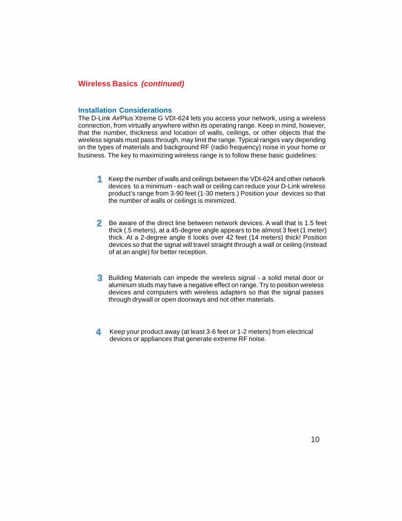
Wireless Basics (continued)
Installation ConsiderationsThe D-Link AirPlus Xtreme G VDI-624 lets you access your network, using a wirelessconnection, from virtually anywhere within its operating range. Keep in mind, however,that the number, thickness and location of walls, ceilings, or other objects that thewireless signals must pass through, may limit the range. Typical ranges vary dependingon the types of materials and background RF (radio frequency) noise in your home orbusiness. The key to maximizing wireless range is to follow these basic guidelines:
Keep the number of walls and ceilings between the VDI-624 and other networkdevices to a minimum - each wall or ceiling can reduce your D-Link wirelessproduct’s range from 3-90 feet (1-30 meters.) Position your devices so thatthe number of walls or ceilings is minimized.
Be aware of the direct line between network devices. A wall that is 1.5 feetthick (.5 meters), at a 45-degree angle appears to be almost 3 feet (1 meter)thick. At a 2-degree angle it looks over 42 feet (14 meters) thick! Positiondevices so that the signal will travel straight through a wall or ceiling (insteadof at an angle) for better reception.
Keep your product away (at least 3-6 feet or 1-2 meters) from electricaldevices or appliances that generate extreme RF noise.
Building Materials can impede the wireless signal - a solid metal door oraluminum studs may have a negative effect on range. Try to position wirelessdevices and computers with wireless adapters so that the signal passesthrough drywall or open doorways and not other materials.
11111
22222
33333
44444
11
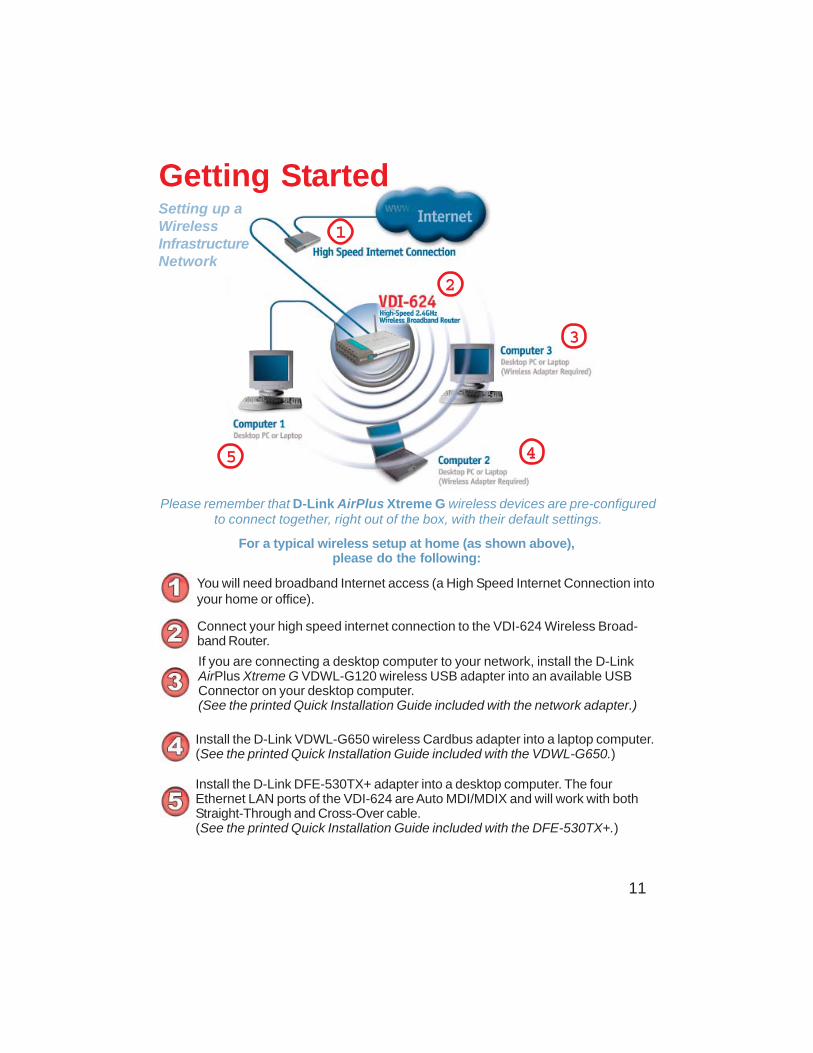
Please remember that D-Link AirPlus Xtreme G wireless devices are pre-configuredto connect together, right out of the box, with their default settings.
You will need broadband Internet access (a High Speed Internet Connection intoyour home or office).
Connect your high speed internet connection to the VDI-624 Wireless Broad-band Router.
If you are connecting a desktop computer to your network, install the D-LinkAirPlus Xtreme G VDWL-G120 wireless USB adapter into an available USBConnector on your desktop computer.(See the printed Quick Installation Guide included with the network adapter.)
Install the D-Link VDWL-G650 wireless Cardbus adapter into a laptop computer.(See the printed Quick Installation Guide included with the VDWL-G650.)
Getting Started
For a typical wireless setup at home (as shown above),please do the following:
Setting up aWirelessInfrastructureNetwork
1
2
3
4
Install the D-Link DFE-530TX+ adapter into a desktop computer. The fourEthernet LAN ports of the VDI-624 are Auto MDI/MDIX and will work with bothStraight-Through and Cross-Over cable.(See the printed Quick Installation Guide included with the DFE-530TX+.)
5
12
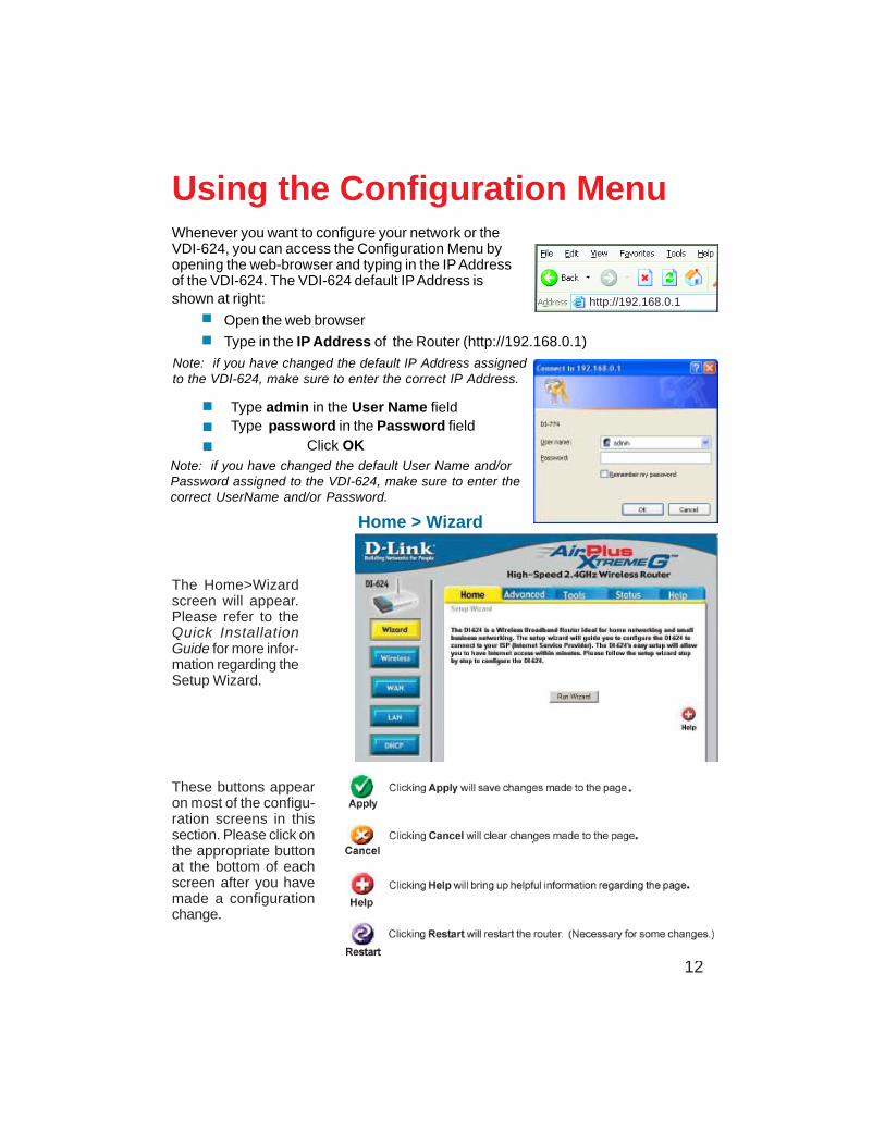
Whenever you want to configure your network or theVDI-624, you can access the Configuration Menu byopening the web-browser and typing in the IP Addressof the VDI-624. The VDI-624 default IP Address isshown at right:
Open the web browser
Type in the IP Address of the Router (http://192.168.0.1)
Using the Configuration Menu
Home > Wizard
The Home>Wizardscreen will appear.Please refer to theQuick InstallationGuide for more infor-mation regarding theSetup Wizard.
Note: if you have changed the default IP Address assignedto the VDI-624, make sure to enter the correct IP Address.
These buttons appearon most of the configu-ration screens in thissection. Please click onthe appropriate buttonat the bottom of eachscreen after you havemade a configurationchange.
http://192.168.0.1
.
.
.
.
Type admin in the User Name fieldType password in the Password field Click OK
Note: if you have changed the default User Name and/orPassword assigned to the VDI-624, make sure to enter thecorrect UserName and/or Password.
13
Using the Configuration Menu (continued)
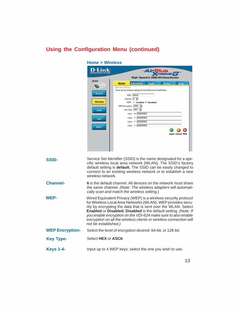
Home > Wireless
Keys 1-4- Input up to 4 WEP keys; select the one you wish to use.
Key Type- Select HEX or ASCII.
WEP Encryption- Select the level of encryption desired: 64-bit, or 128-bit.
SSID- Service Set Identifier (SSID) is the name designated for a spe-cific wireless local area network (WLAN). The SSID’s factorydefault setting is default. The SSID can be easily changed toconnect to an existing wireless network or to establish a newwireless network.
WEP- Wired Equivalent Privacy (WEP) is a wireless security protocolfor Wireless Local Area Networks (WLAN). WEP provides secu-rity by encrypting the data that is sent over the WLAN. SelectEnabled or Disabled. Disabled is the default setting. (Note: Ifyou enable encryption on the VDI-624 make sure to also enableencryption on all the wireless clients or wireless connection willnot be established.)
Channel- 6 is the default channel. All devices on the network must sharethe same channel. (Note: The wireless adapters will automati-cally scan and match the wireless setting.)
14
Using the Configuration Menu (continued)
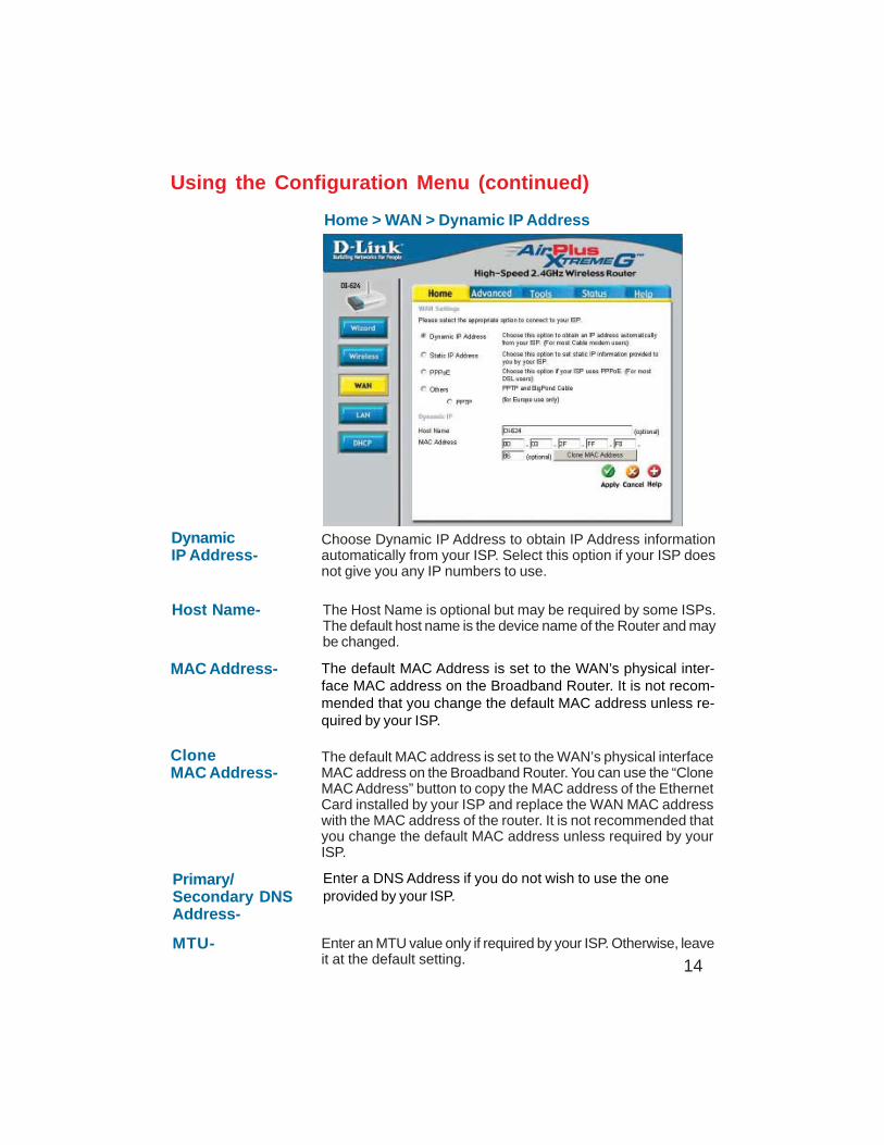
Home > WAN > Dynamic IP Address
DI-754
Host Name- The Host Name is optional but may be required by some ISPs.The default host name is the device name of the Router and maybe changed.
MAC Address- The default MAC Address is set to the WAN’s physical inter-face MAC address on the Broadband Router. It is not recom-mended that you change the default MAC address unless re-quired by your ISP.
CloneMAC Address-
The default MAC address is set to the WAN’s physical interfaceMAC address on the Broadband Router. You can use the “CloneMAC Address” button to copy the MAC address of the EthernetCard installed by your ISP and replace the WAN MAC addresswith the MAC address of the router. It is not recommended thatyou change the default MAC address unless required by yourISP.
DynamicIP Address-
Choose Dynamic IP Address to obtain IP Address informationautomatically from your ISP. Select this option if your ISP doesnot give you any IP numbers to use.
Primary/Secondary DNSAddress-
Enter an MTU value only if required by your ISP. Otherwise, leaveit at the default setting.
MTU-
Enter a DNS Address if you do not wish to use the oneprovided by your ISP.
15
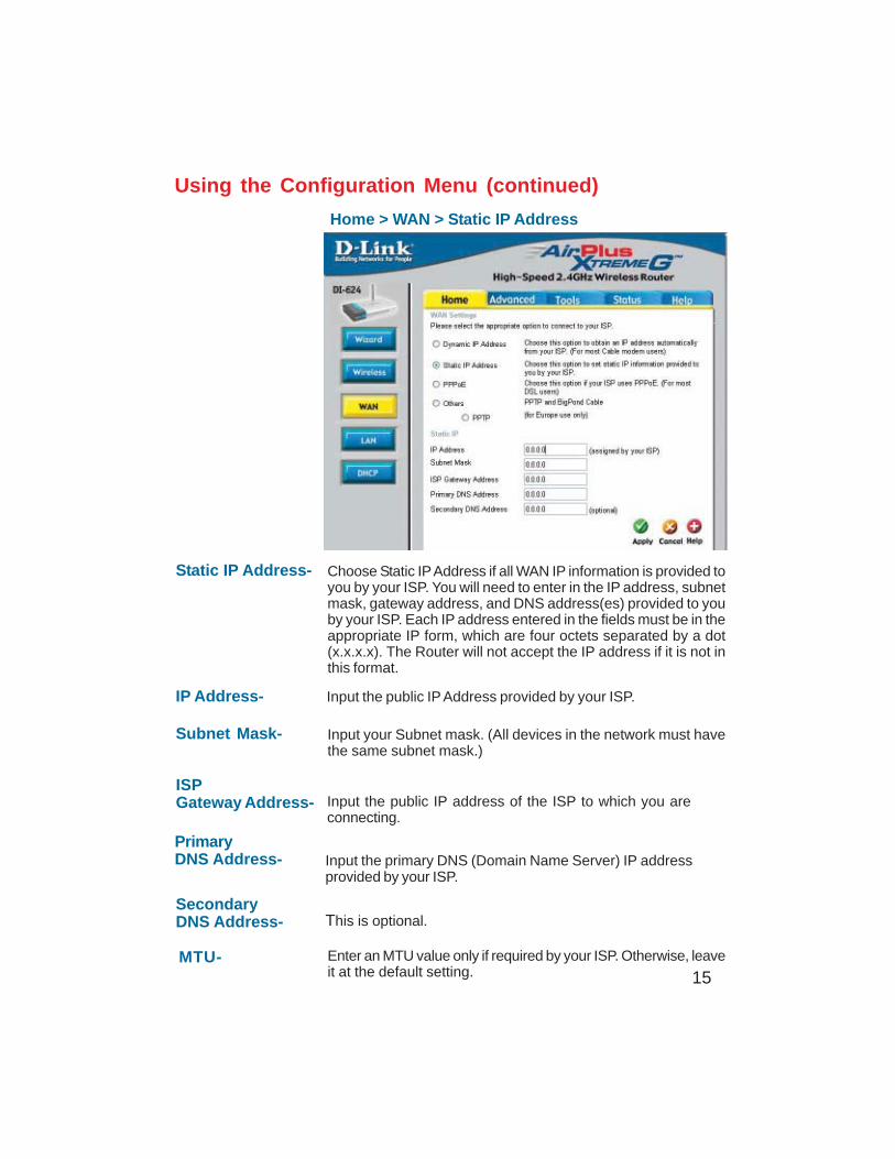
Home > WAN > Static IP Address
Static IP Address-
IP Address-
Subnet Mask-
ISPGateway Address-
PrimaryDNS Address-
SecondaryDNS Address-
Choose Static IP Address if all WAN IP information is provided toyou by your ISP. You will need to enter in the IP address, subnetmask, gateway address, and DNS address(es) provided to youby your ISP. Each IP address entered in the fields must be in theappropriate IP form, which are four octets separated by a dot(x.x.x.x). The Router will not accept the IP address if it is not inthis format.
Input the public IP Address provided by your ISP.
Input your Subnet mask. (All devices in the network must havethe same subnet mask.)
Input the public IP address of the ISP to which you areconnecting.
Input the primary DNS (Domain Name Server) IP addressprovided by your ISP.
This is optional.
Enter an MTU value only if required by your ISP. Otherwise, leaveit at the default setting.
MTU-
Using the Configuration Menu (continued)
16
Using the Configuration Menu (continued)
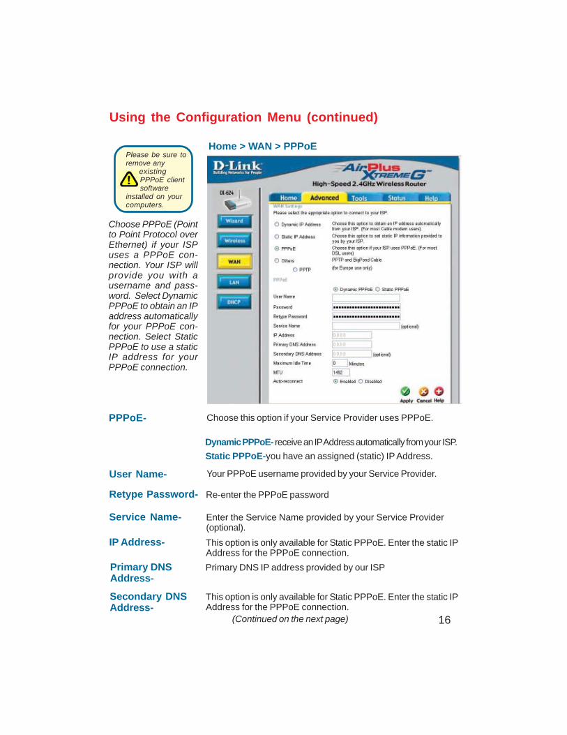
Home > WAN > PPPoE
IP Address- This option is only available for Static PPPoE. Enter the static IPAddress for the PPPoE connection.
(Continued on the next page)
User Name- Your PPPoE username provided by your Service Provider.
Service Name- Enter the Service Name provided by your Service Provider(optional).
Retype Password- Re-enter the PPPoE password
PPPoE-
Static PPPoE-you have an assigned (static) IP Address.
Choose this option if your Service Provider uses PPPoE.
Dynamic PPPoE- receive an IP Address automatically from your ISP.
Primary DNSAddress-
Primary DNS IP address provided by our ISP
Secondary DNSAddress-
This option is only available for Static PPPoE. Enter the static IPAddress for the PPPoE connection.
Choose PPPoE (Pointto Point Protocol overEthernet) if your ISPuses a PPPoE con-nection. Your ISP willprovide you with ausername and pass-word. Select DynamicPPPoE to obtain an IPaddress automaticallyfor your PPPoE con-nection. Select StaticPPPoE to use a staticIP address for yourPPPoE connection.
Please be sure toremove any
existingPPPoE clientsoftware
installed on yourcomputers.
17
Using the Configuration Menu (continued)
Home > WAN > PPPoE continued
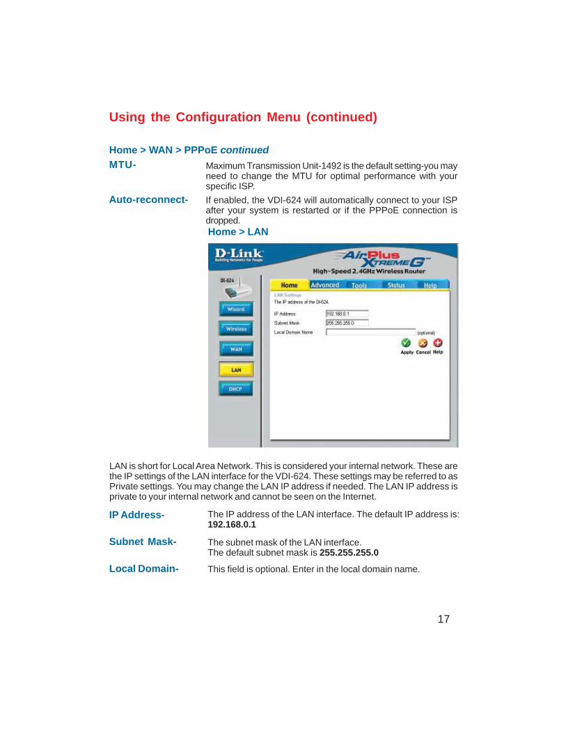
Home > LAN
LAN is short for Local Area Network. This is considered your internal network. These arethe IP settings of the LAN interface for the VDI-624. These settings may be referred to asPrivate settings. You may change the LAN IP address if needed. The LAN IP address isprivate to your internal network and cannot be seen on the Internet.
Auto-reconnect- If enabled, the VDI-624 will automatically connect to your ISPafter your system is restarted or if the PPPoE connection isdropped.
MTU- Maximum Transmission Unit-1492 is the default setting-you mayneed to change the MTU for optimal performance with yourspecific ISP.
Local Domain- This field is optional. Enter in the local domain name.
Subnet Mask- The subnet mask of the LAN interface.The default subnet mask is 255.255.255.0
IP Address- The IP address of the LAN interface. The default IP address is:192.168.0.1
18
Using the Configuration Menu (continued)
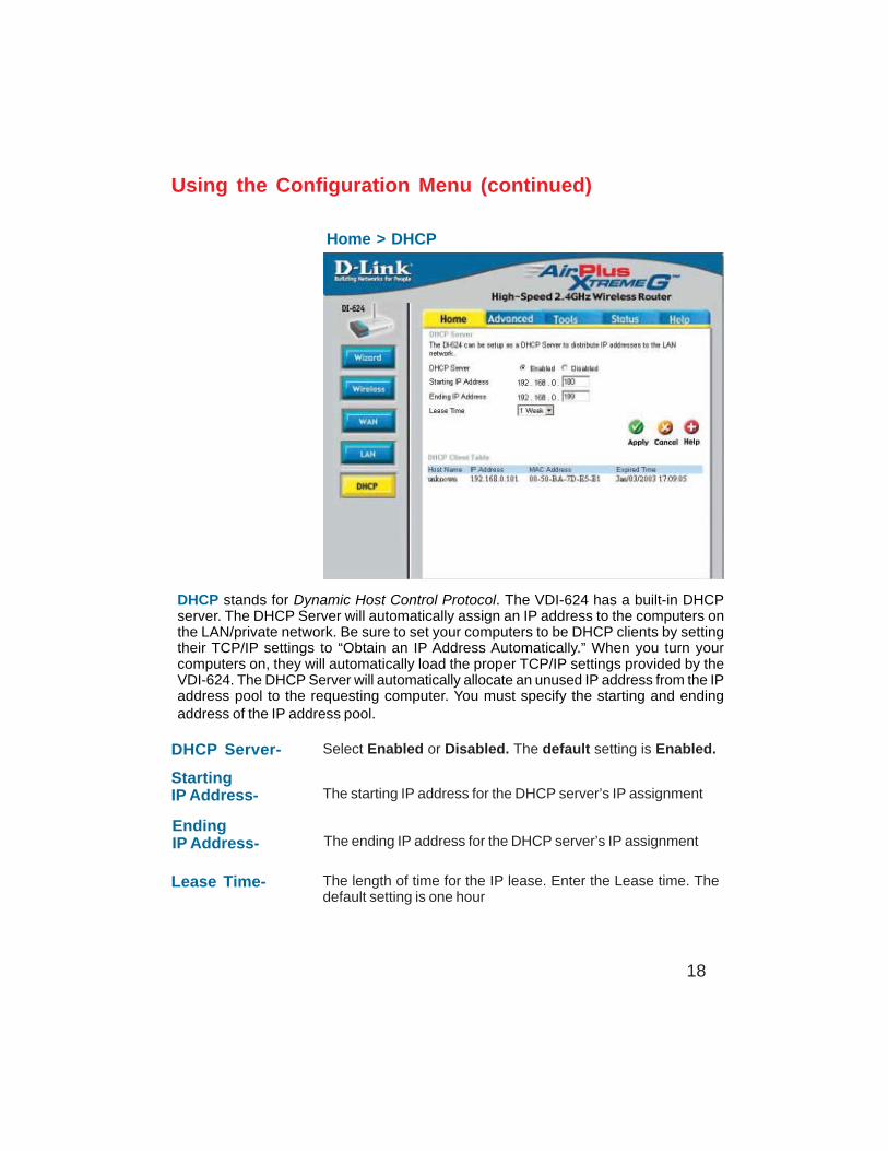
Home > DHCP
DHCP stands for Dynamic Host Control Protocol. The VDI-624 has a built-in DHCPserver. The DHCP Server will automatically assign an IP address to the computers onthe LAN/private network. Be sure to set your computers to be DHCP clients by settingtheir TCP/IP settings to “Obtain an IP Address Automatically.” When you turn yourcomputers on, they will automatically load the proper TCP/IP settings provided by theVDI-624. The DHCP Server will automatically allocate an unused IP address from the IPaddress pool to the requesting computer. You must specify the starting and endingaddress of the IP address pool.
DHCP Server- Select Enabled or Disabled. The default setting is Enabled.
StartingIP Address- The starting IP address for the DHCP server’s IP assignment
EndingIP Address- The ending IP address for the DHCP server’s IP assignment
Lease Time- The length of time for the IP lease. Enter the Lease time. Thedefault setting is one hour
DI-754
19
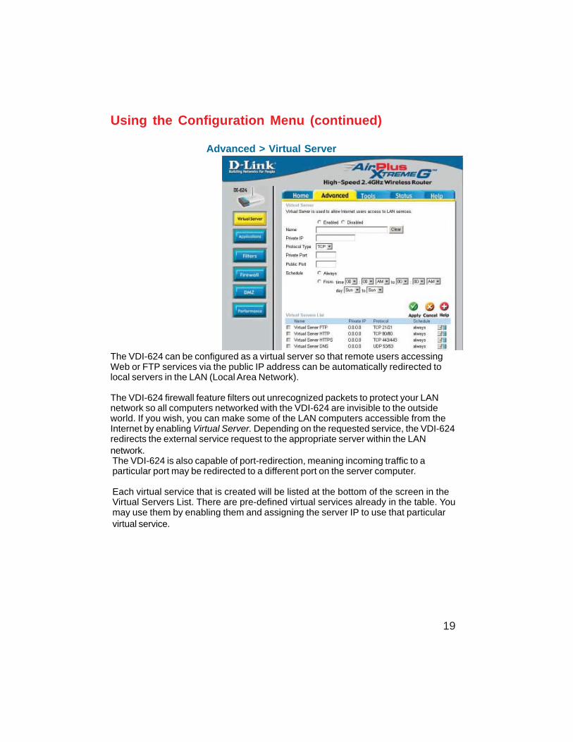
Advanced > Virtual Server
Using the Configuration Menu (continued)
The VDI-624 is also capable of port-redirection, meaning incoming traffic to aparticular port may be redirected to a different port on the server computer.
Each virtual service that is created will be listed at the bottom of the screen in theVirtual Servers List. There are pre-defined virtual services already in the table. Youmay use them by enabling them and assigning the server IP to use that particularvirtual service.
The VDI-624 can be configured as a virtual server so that remote users accessingWeb or FTP services via the public IP address can be automatically redirected tolocal servers in the LAN (Local Area Network).
The VDI-624 firewall feature filters out unrecognized packets to protect your LANnetwork so all computers networked with the VDI-624 are invisible to the outsideworld. If you wish, you can make some of the LAN computers accessible from theInternet by enabling Virtual Server. Depending on the requested service, the VDI-624redirects the external service request to the appropriate server within the LANnetwork.
20
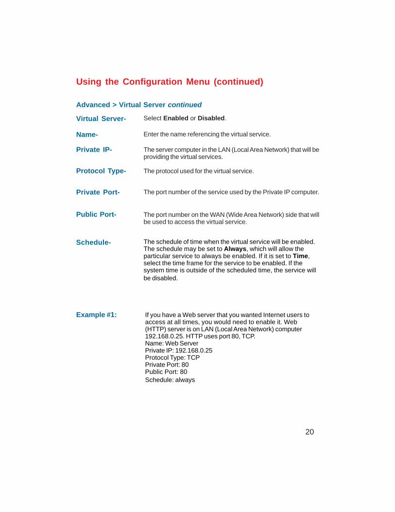
Advanced > Virtual Server continued
Using the Configuration Menu (continued)
Example #1:
Protocol Type- The protocol used for the virtual service.
Public Port- The port number on the WAN (Wide Area Network) side that willbe used to access the virtual service.
Private Port- The port number of the service used by the Private IP computer.
Schedule- The schedule of time when the virtual service will be enabled.The schedule may be set to Always, which will allow theparticular service to always be enabled. If it is set to Time,select the time frame for the service to be enabled. If thesystem time is outside of the scheduled time, the service willbe disabled.
Virtual Server- Select Enabled or Disabled.
Name- Enter the name referencing the virtual service.
Private IP- The server computer in the LAN (Local Area Network) that will beproviding the virtual services.
If you have a Web server that you wanted Internet users toaccess at all times, you would need to enable it. Web(HTTP) server is on LAN (Local Area Network) computer192.168.0.25. HTTP uses port 80, TCP.Name: Web ServerPrivate IP: 192.168.0.25Protocol Type: TCPPrivate Port: 80Public Port: 80Schedule: always
21
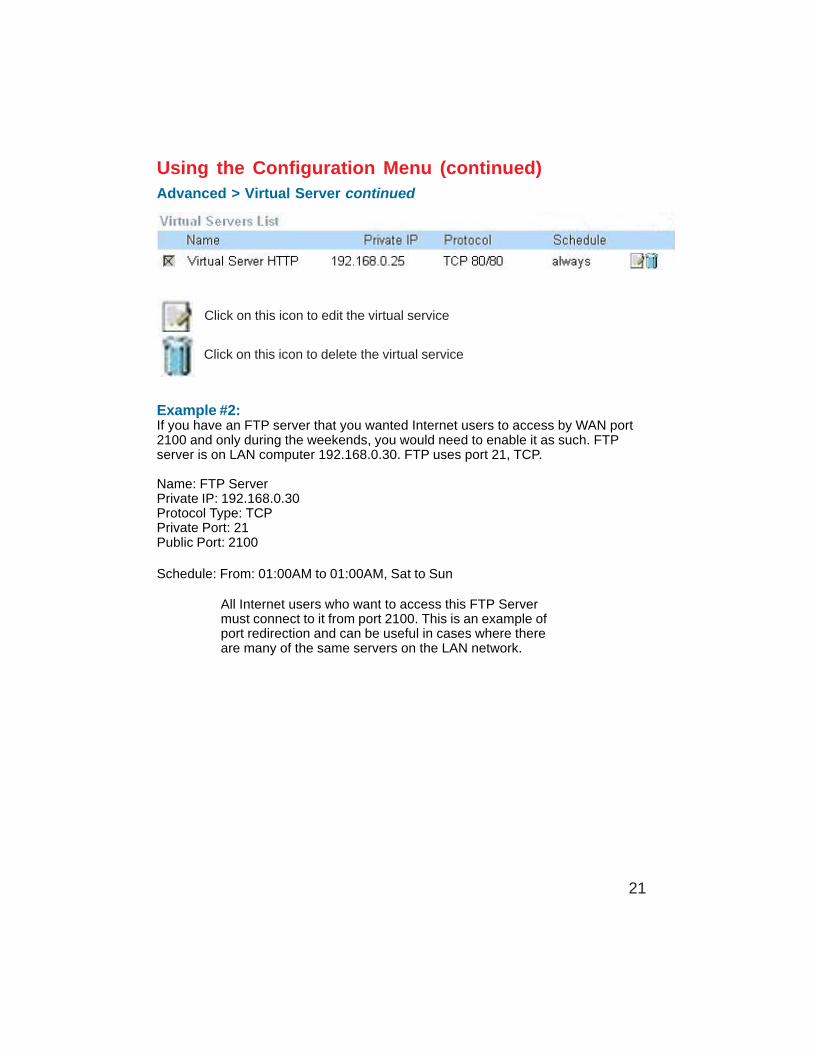
Example #2:If you have an FTP server that you wanted Internet users to access by WAN port2100 and only during the weekends, you would need to enable it as such. FTPserver is on LAN computer 192.168.0.30. FTP uses port 21, TCP.
Name: FTP ServerPrivate IP: 192.168.0.30Protocol Type: TCPPrivate Port: 21Public Port: 2100
Schedule: From: 01:00AM to 01:00AM, Sat to Sun
Using the Configuration Menu (continued)Advanced > Virtual Server continued
Click on this icon to edit the virtual service
Click on this icon to delete the virtual service
All Internet users who want to access this FTP Servermust connect to it from port 2100. This is an example ofport redirection and can be useful in cases where thereare many of the same servers on the LAN network.
22
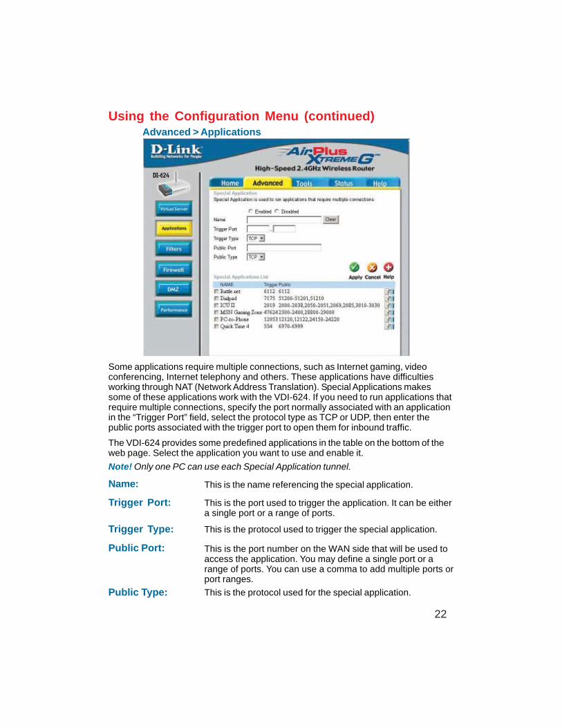
Using the Configuration Menu (continued)Advanced > Applications
Some applications require multiple connections, such as Internet gaming, videoconferencing, Internet telephony and others. These applications have difficultiesworking through NAT (Network Address Translation). Special Applications makessome of these applications work with the VDI-624. If you need to run applications thatrequire multiple connections, specify the port normally associated with an applicationin the “Trigger Port” field, select the protocol type as TCP or UDP, then enter thepublic ports associated with the trigger port to open them for inbound traffic.
The VDI-624 provides some predefined applications in the table on the bottom of theweb page. Select the application you want to use and enable it.
Note! Only one PC can use each Special Application tunnel.
Name: This is the name referencing the special application.
Trigger Port: This is the port used to trigger the application. It can be eithera single port or a range of ports.
Trigger Type: This is the protocol used to trigger the special application.
Public Port: This is the port number on the WAN side that will be used toaccess the application. You may define a single port or arange of ports. You can use a comma to add multiple ports orport ranges.
Public Type: This is the protocol used for the special application.
23
Using the Configuration Menu (continued)
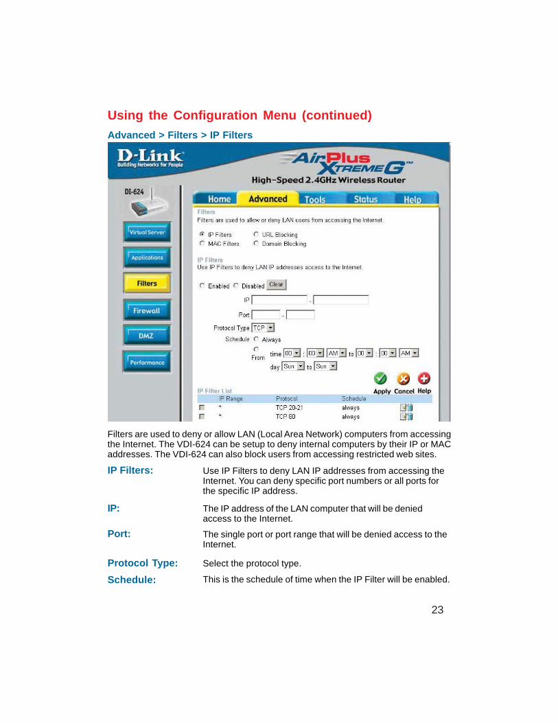
Advanced > Filters > IP Filters
Filters are used to deny or allow LAN (Local Area Network) computers from accessingthe Internet. The VDI-624 can be setup to deny internal computers by their IP or MACaddresses. The VDI-624 can also block users from accessing restricted web sites.
This is the schedule of time when the IP Filter will be enabled.Schedule:
Select the protocol type.Protocol Type:
Use IP Filters to deny LAN IP addresses from accessing theInternet. You can deny specific port numbers or all ports forthe specific IP address.
IP Filters:
The single port or port range that will be denied access to theInternet.
Port:
The IP address of the LAN computer that will be deniedaccess to the Internet.
IP:
24
Using the Configuration Menu (continued)
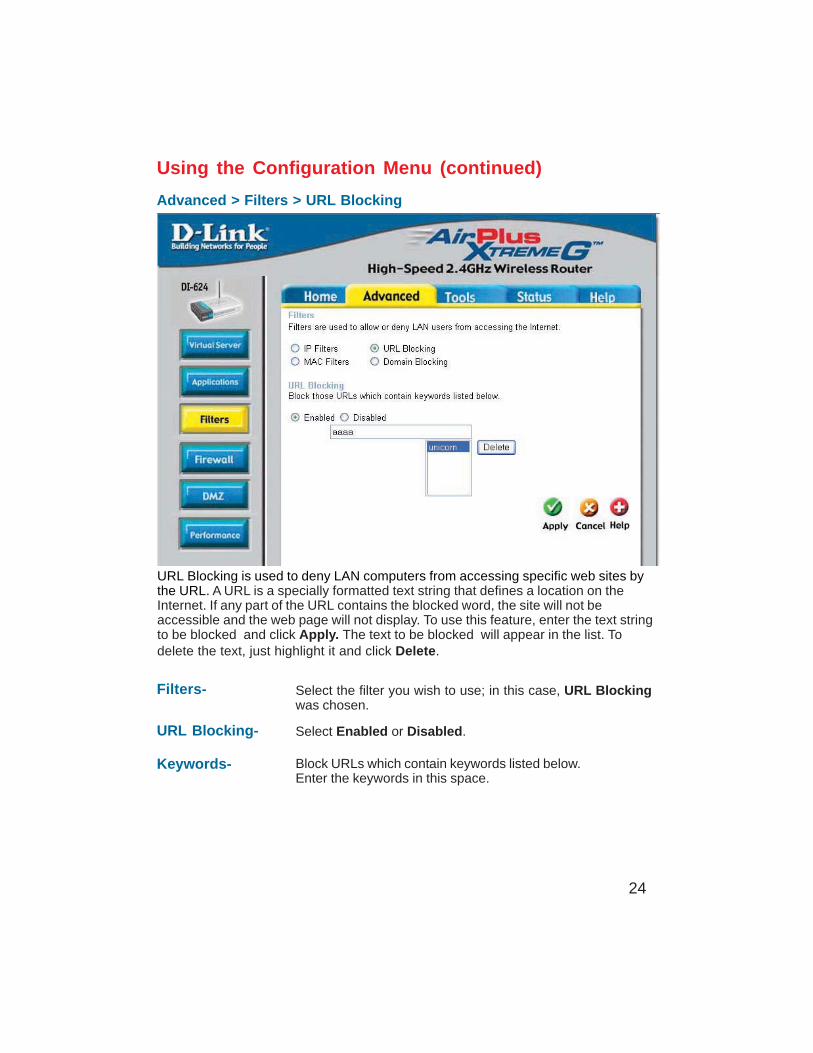
Advanced > Filters > URL Blocking
Filters-
URL Blocking is used to deny LAN computers from accessing specific web sites bythe URL. A URL is a specially formatted text string that defines a location on theInternet. If any part of the URL contains the blocked word, the site will not beaccessible and the web page will not display. To use this feature, enter the text stringto be blocked and click Apply. The text to be blocked will appear in the list. Todelete the text, just highlight it and click Delete.
Select the filter you wish to use; in this case, URL Blockingwas chosen.
Keywords- Block URLs which contain keywords listed below.Enter the keywords in this space.
URL Blocking- Select Enabled or Disabled.
25
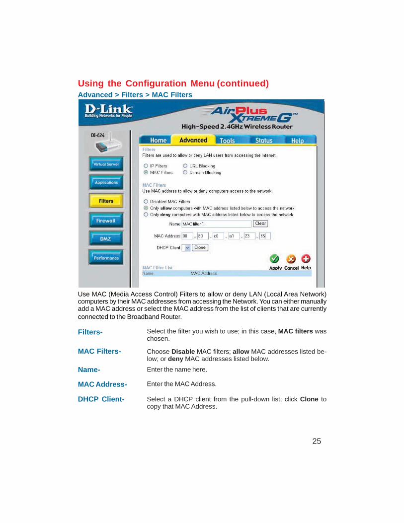
Using the Configuration MenuAdvanced > Filters > MAC Filters
Use MAC (Media Access Control) Filters to allow or deny LAN (Local Area Network)computers by their MAC addresses from accessing the Network. You can either manuallyadd a MAC address or select the MAC address from the list of clients that are currentlyconnected to the Broadband Router.
MAC Filters- Choose Disable MAC filters; allow MAC addresses listed be-low; or deny MAC addresses listed below.
Filters-
Name- Enter the name here.
MAC Address- Enter the MAC Address.
DHCP Client- Select a DHCP client from the pull-down list; click Clone tocopy that MAC Address.
Select the filter you wish to use; in this case, MAC filters waschosen.
(continued)
26
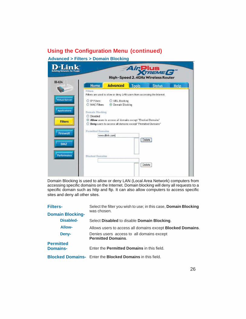
Using the Configuration MenuAdvanced > Filters > Domain Blocking
Filters-
Domain Blocking-
Blocked Domains-
PermittedDomains-
Domain Blocking is used to allow or deny LAN (Local Area Network) computers fromaccessing specific domains on the Internet. Domain blocking will deny all requests to aspecific domain such as http and ftp. It can also allow computers to access specificsites and deny all other sites.
Select the filter you wish to use; in this case, Domain Blockingwas chosen.
Disabled-
Allow-
Deny-
Enter the Permitted Domains in this field.
Enter the Blocked Domains in this field.
Select Disabled to disable Domain Blocking.
Allows users to access all domains except Blocked Domains.
Denies users access to all domains exceptPermitted Domains.
(continued)
27
Using the Configuration Menu (continued)
Advanced > Firewall
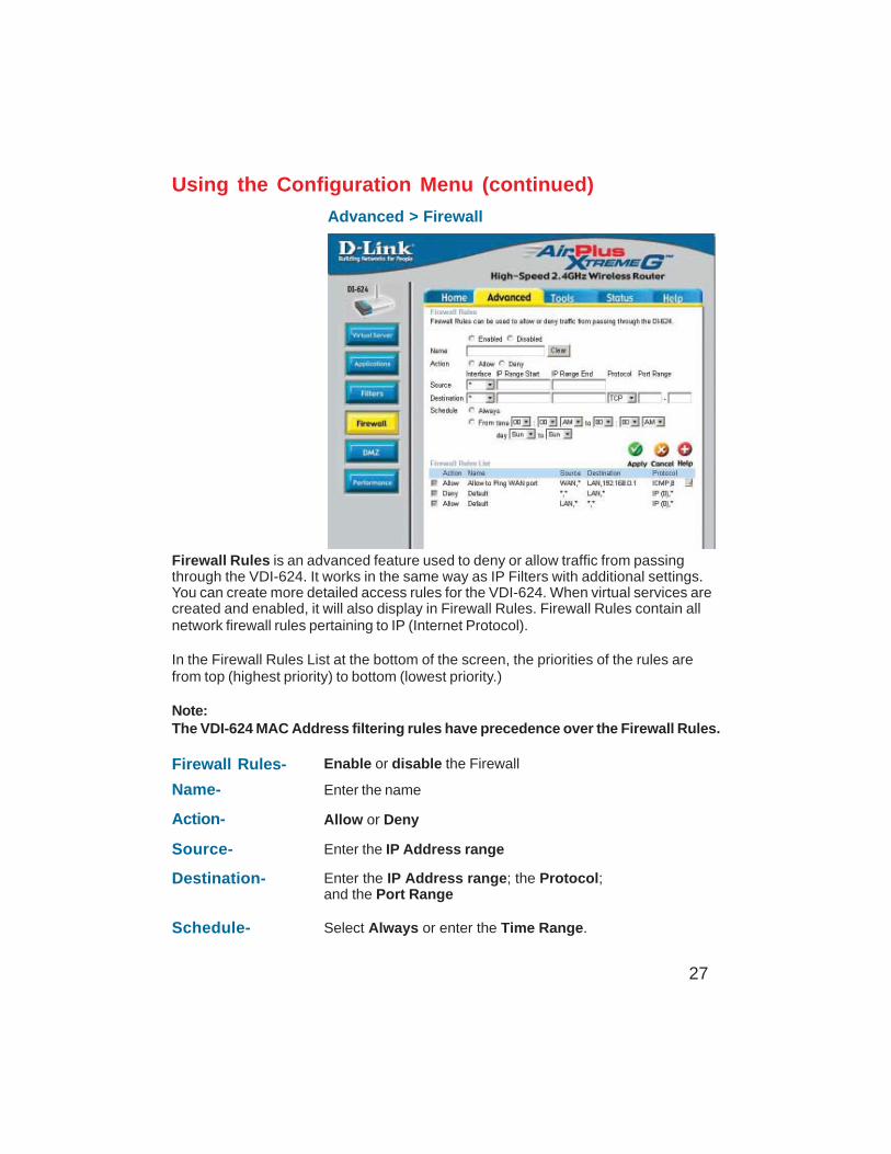
Firewall Rules is an advanced feature used to deny or allow traffic from passingthrough the VDI-624. It works in the same way as IP Filters with additional settings.You can create more detailed access rules for the VDI-624. When virtual services arecreated and enabled, it will also display in Firewall Rules. Firewall Rules contain allnetwork firewall rules pertaining to IP (Internet Protocol).
In the Firewall Rules List at the bottom of the screen, the priorities of the rules arefrom top (highest priority) to bottom (lowest priority.)
Note:The VDI-624 MAC Address filtering rules have precedence over the Firewall Rules.
Firewall Rules- Enable or disable the Firewall
Name- Enter the name
Action- Allow or Deny
Source- Enter the IP Address range
Schedule- Select Always or enter the Time Range.
Destination- Enter the IP Address range; the Protocol;and the Port Range
28
Advanced > DMZ
Using the Configuration Menu (continued)
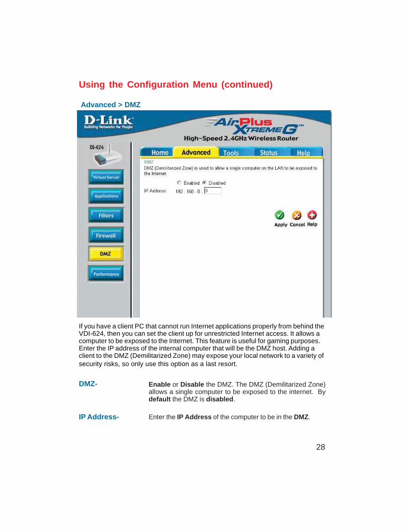
If you have a client PC that cannot run Internet applications properly from behind theVDI-624, then you can set the client up for unrestricted Internet access. It allows acomputer to be exposed to the Internet. This feature is useful for gaming purposes.Enter the IP address of the internal computer that will be the DMZ host. Adding aclient to the DMZ (Demilitarized Zone) may expose your local network to a variety ofsecurity risks, so only use this option as a last resort.
DMZ- Enable or Disable the DMZ. The DMZ (Demilitarized Zone)allows a single computer to be exposed to the internet. Bydefault the DMZ is disabled.
IP Address- Enter the IP Address of the computer to be in the DMZ.
29
Using the Configuration Menu (continued)
Advanced > Performance
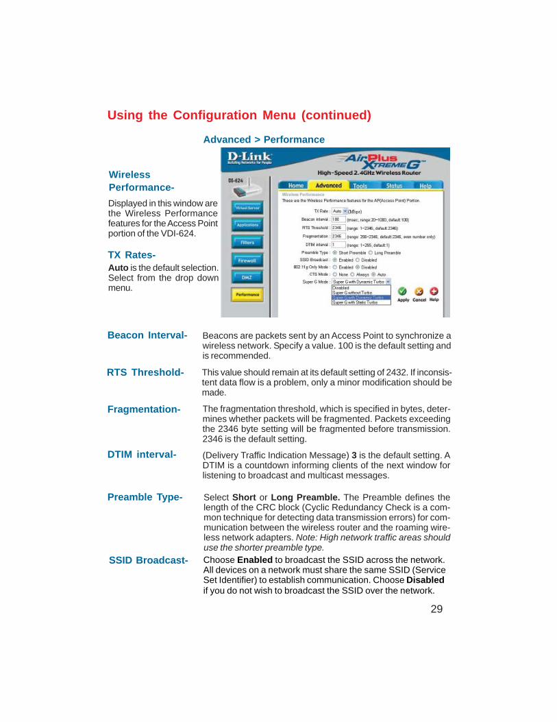
Preamble Type- Select Short or Long Preamble. The Preamble defines thelength of the CRC block (Cyclic Redundancy Check is a com-mon technique for detecting data transmission errors) for com-munication between the wireless router and the roaming wire-less network adapters. Note: High network traffic areas shoulduse the shorter preamble type.
Beacon Interval- Beacons are packets sent by an Access Point to synchronize awireless network. Specify a value. 100 is the default setting andis recommended.
RTS Threshold- This value should remain at its default setting of 2432. If inconsis-tent data flow is a problem, only a minor modification should bemade.
Fragmentation- The fragmentation threshold, which is specified in bytes, deter-mines whether packets will be fragmented. Packets exceedingthe 2346 byte setting will be fragmented before transmission.2346 is the default setting.
DTIM interval- (Delivery Traffic Indication Message) 3 is the default setting. ADTIM is a countdown informing clients of the next window forlistening to broadcast and multicast messages.
WirelessPerformance-
Displayed in this window arethe Wireless Performancefeatures for the Access Pointportion of the VDI-624.
TX Rates-Auto is the default selection.Select from the drop downmenu.
SSID Broadcast- Choose Enabled to broadcast the SSID across the network.All devices on a network must share the same SSID (ServiceSet Identifier) to establish communication. Choose Disabledif you do not wish to broadcast the SSID over the network.
30
Super G Mode- Super G is a group of performance enhancement features thatincrease end user application throughput in an 802.11g network.Super G is backwards compatible to standard 802.11g devices.For top performance, all wirelss devices on the network shouldbe Super G capable. Select either Disabled, Super G withoutTurbo, Super G with Dynamic Turbo, or Super G with Static Turbo.
Disabled- Standard 802.11g support, no enhanced capabilities.
Super G withoutTurbo-
Capable of Packet Bursting, FastFrames, Compression, and noTurbo mode.
Super G withDynamic Turbo-
Capable of Packet Bursting, FastFrames, Compression, andDynamic Turbo. This setting is backwards compatible with non-Turbo (legacy) devices. Dynamic Turbo mode is only enabledwhen all nodes on the wireless network are Super G with Dy-namic Turbo enabled.
802.11g only mode- Select this mode to restrict your network to only those devicesthat employ the 802.11g standard. Enabling this mode will en-sure that you maintain the highest connectivity rate, unhamperedby any connection to an 802.11b device.
CTS Mode- CTS (Clear To Send) is a function used to minimize collisionsamong wireless devices on a wireless local area network (LAN).CTS will make sure the wireless network is clear before a wire-less client attempts to send wireless data. Enabling CTS willadd overhead and may lower wireless throughput.
Auto- CTS will monitor the wireless network and automati-cally decide whether to implement CTS based onthe amount of traffic and collisions that occurs onthe wireless network.
Always- CTS will always be used to make sure the wirelessLAN is clear before sending data.
None- CTS is typically used in a pure 802.11g environment.If CTS is set to “None” in a mixed mode environmentpopulated by 802.11b clients, wireless collisions mayoccur frequently.
Super G withStatic Turbo-
Capable of Packet Bursting, FastFrames, Compression, andStatic Turbo. This setting is not backwards compatible with non-Turbo (legacy) devices. Static turbo mode is always on and isonly enabled when all nodes on the wireless network is Super Gwith Static Turbo enabled.
Using the Configuration Menu (continued)
Advanced > Performance (continued)
31
Using the Configuration Menu (continued)
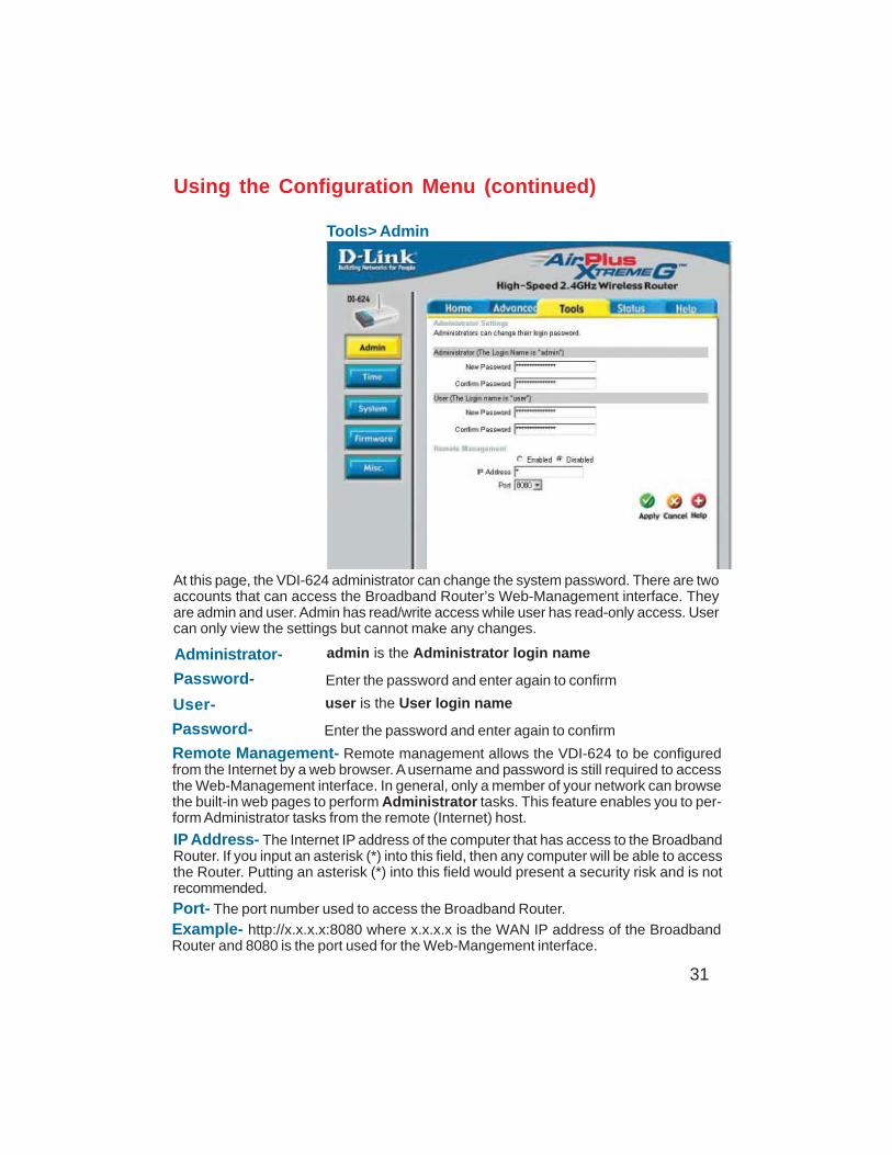
Tools> Admin
At this page, the VDI-624 administrator can change the system password. There are twoaccounts that can access the Broadband Router’s Web-Management interface. Theyare admin and user. Admin has read/write access while user has read-only access. Usercan only view the settings but cannot make any changes.
Remote Management- Remote management allows the VDI-624 to be configuredfrom the Internet by a web browser. A username and password is still required to accessthe Web-Management interface. In general, only a member of your network can browsethe built-in web pages to perform Administrator tasks. This feature enables you to per-form Administrator tasks from the remote (Internet) host.
IP Address- The Internet IP address of the computer that has access to the BroadbandRouter. If you input an asterisk (*) into this field, then any computer will be able to accessthe Router. Putting an asterisk (*) into this field would present a security risk and is notrecommended.
Port- The port number used to access the Broadband Router.
Example- http://x.x.x.x:8080 where x.x.x.x is the WAN IP address of the BroadbandRouter and 8080 is the port used for the Web-Mangement interface.
Administrator-
Password-
admin is the Administrator login name
Enter the password and enter again to confirm
User-
Password-
user is the User login name
Enter the password and enter again to confirm
32
Using the Configuration Menu (continued)
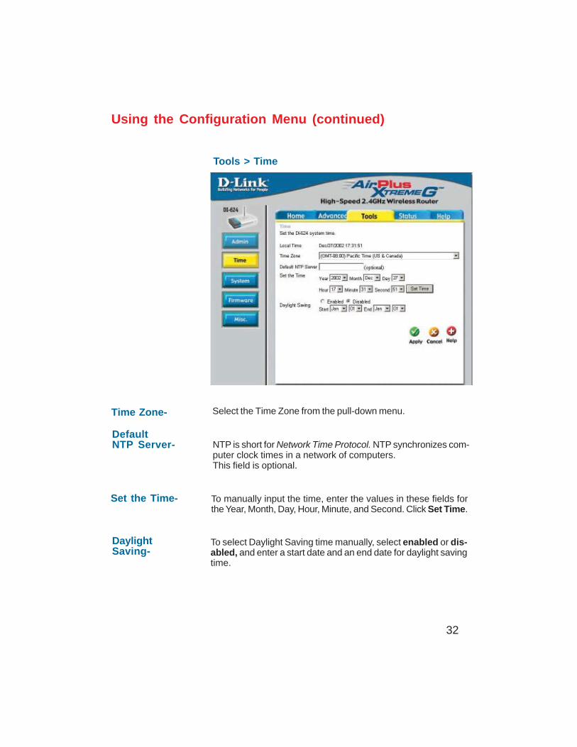
Tools > Time
Time Zone- Select the Time Zone from the pull-down menu.
DaylightSaving-
To select Daylight Saving time manually, select enabled or dis-abled, and enter a start date and an end date for daylight savingtime.
Set the Time- To manually input the time, enter the values in these fields forthe Year, Month, Day, Hour, Minute, and Second. Click Set Time.
DefaultNTP Server- NTP is short for Network Time Protocol. NTP synchronizes com-
puter clock times in a network of computers.This field is optional.
33
Using the Configuration Menu (continued)
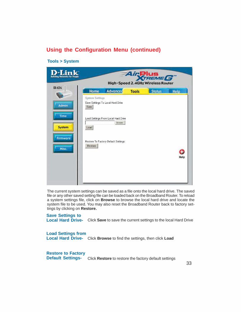
Tools > System
The current system settings can be saved as a file onto the local hard drive. The savedfile or any other saved setting file can be loaded back on the Broadband Router. To reloada system settings file, click on Browse to browse the local hard drive and locate thesystem file to be used. You may also reset the Broadband Router back to factory set-tings by clicking on Restore.
Click Save to save the current settings to the local Hard Drive
Click Browse to find the settings, then click Load
Save Settings toLocal Hard Drive-
Load Settings fromLocal Hard Drive-
Restore to FactoryDefault Settings- Click Restore to restore the factory default settings
Browse
34
Using the Configuration Menu (continued)
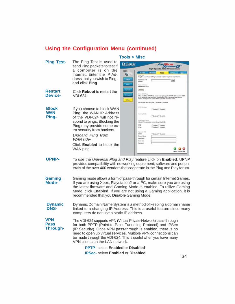
Tools > MiscPing Test-
RestartDevice-
BlockWANPing-
Discard Ping fromWAN side-
VPNPassThrough-
PPTP- select Enabled or DisabledIPSec- select Enabled or Disabled
The Ping Test is used tosend Ping packets to test ifa computer is on theInternet. Enter the IP Ad-dress that you wish to Ping,and click Ping.
If you choose to block WANPing, the WAN IP Addressof the VDI-624 will not re-spond to pings. Blocking thePing may provide some ex-tra security from hackers.
The VDI-624 supports VPN (Virtual Private Network) pass-throughfor both PPTP (Point-to-Point Tunneling Protocol) and IPSec(IP Security). Once VPN pass-through is enabled, there is noneed to open up virtual services. Multiple VPN connections canbe made through the VDI-624. This is useful when you have manyVPN clients on the LAN network.
Click Reboot to restart theVDI-624.
Click Enabled to block theWAN ping.
UPNP-
GamingMode-
DynamicDNS-
To use the Universal Plug and Play feature click on Enabled. UPNPprovides compatibility with networking equipment, software and periph-erals of the over 400 vendors that cooperate in the Plug and Play forum.
Gaming mode allows a form of pass-through for certain Internet Games.If you are using Xbox, Playstation2 or a PC, make sure you are usingthe latest firmware and Gaming Mode is enabled. To utilize GamingMode, click Enabled. If you are not using a Gaming application, it isrecommended that you Disable Gaming Mode.
Dynamic Domain Name System is a method of keeping a domain namelinked to a changing IP Address. This is a useful feature since manycomputers do not use a static IP address.
35
Using the Configuration Menu (continued)
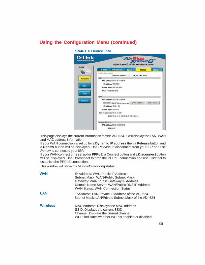
Status > Device Info
This page displays the current information for the VDI-624. It will display the LAN, WANand MAC address information.If your WAN connection is set up for a Dynamic IP address then a Release button anda Renew button will be displayed. Use Release to disconnect from your ISP and useRenew to connect to your ISP.If your WAN connection is set up for PPPoE, a Connect button and a Disconnect buttonwill be displayed. Use Disconnect to drop the PPPoE connection and use Connect toestablish the PPPoE connection.This window will show the VDI-624’s working status:
IP Address: WAN/Public IP AddressSubnet Mask: WAN/Public Subnet MaskGateway: WAN/Public Gateway IP AddressDomain Name Server: WAN/Public DNS IP AddressWAN Status: WAN Connection Status
Wireless
IP Address: LAN/Private IP Address of the VDI-624Subnet Mask: LAN/Private Subnet Mask of the VDI-624
WAN
LAN
MAC Address: Displays the MAC addressSSID: Displays the current SSIDChannel: Displays the current channelWEP: indicates whether WEP is enabled or disabled
36
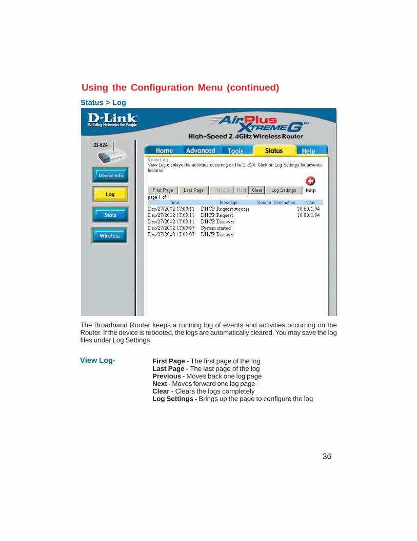
The Broadband Router keeps a running log of events and activities occurring on theRouter. If the device is rebooted, the logs are automatically cleared. You may save the logfiles under Log Settings.
Using the Configuration Menu (continued)
Status > Log
View Log-
DI-754
First Page - The first page of the logLast Page - The last page of the logPrevious - Moves back one log pageNext - Moves forward one log pageClear - Clears the logs completelyLog Settings - Brings up the page to configure the log
37
Using the Configuration Menu (continued)
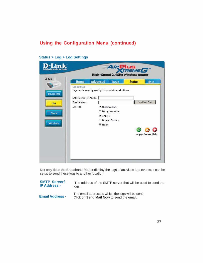
Status > Log > Log Settings
Not only does the Broadband Router display the logs of activities and events, it can besetup to send these logs to another location.
The address of the SMTP server that will be used to send thelogs.
The email address to which the logs will be sent.Click on Send Mail Now to send the email.
SMTP Server/IP Address -
Email Address -
38
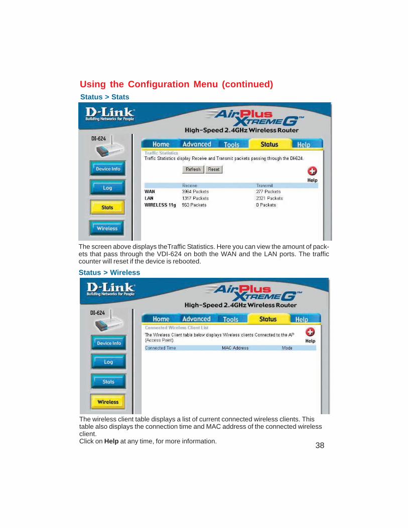
Status > Wireless
Using the Configuration Menu (continued)Status > Stats
The screen above displays theTraffic Statistics. Here you can view the amount of pack-ets that pass through the VDI-624 on both the WAN and the LAN ports. The trafficcounter will reset if the device is rebooted.
The wireless client table displays a list of current connected wireless clients. Thistable also displays the connection time and MAC address of the connected wirelessclient.Click on Help at any time, for more information.
39
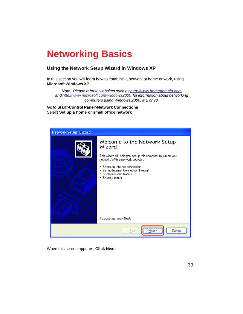
Using the Network Setup Wizard in Windows XP
In this section you will learn how to establish a network at home or work, usingMicrosoft Windows XP.
Note: Please refer to websites such as http://www.homenethelp.comand http://www.microsoft.com/windows2000 for information about networking
computers using Windows 2000, ME or 98.
Go to Start>Control Panel>Network ConnectionsSelect Set up a home or small office network
Networking Basics
When this screen appears, Click Next.
40
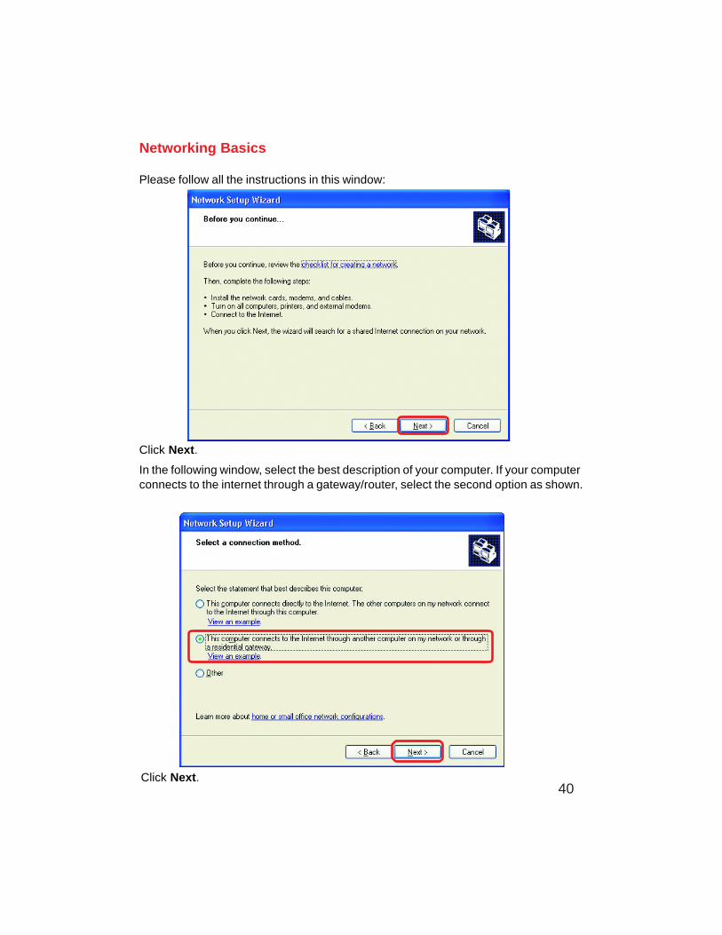
Please follow all the instructions in this window:
Networking Basics
Click Next.
In the following window, select the best description of your computer. If your computerconnects to the internet through a gateway/router, select the second option as shown.
Click Next.
41
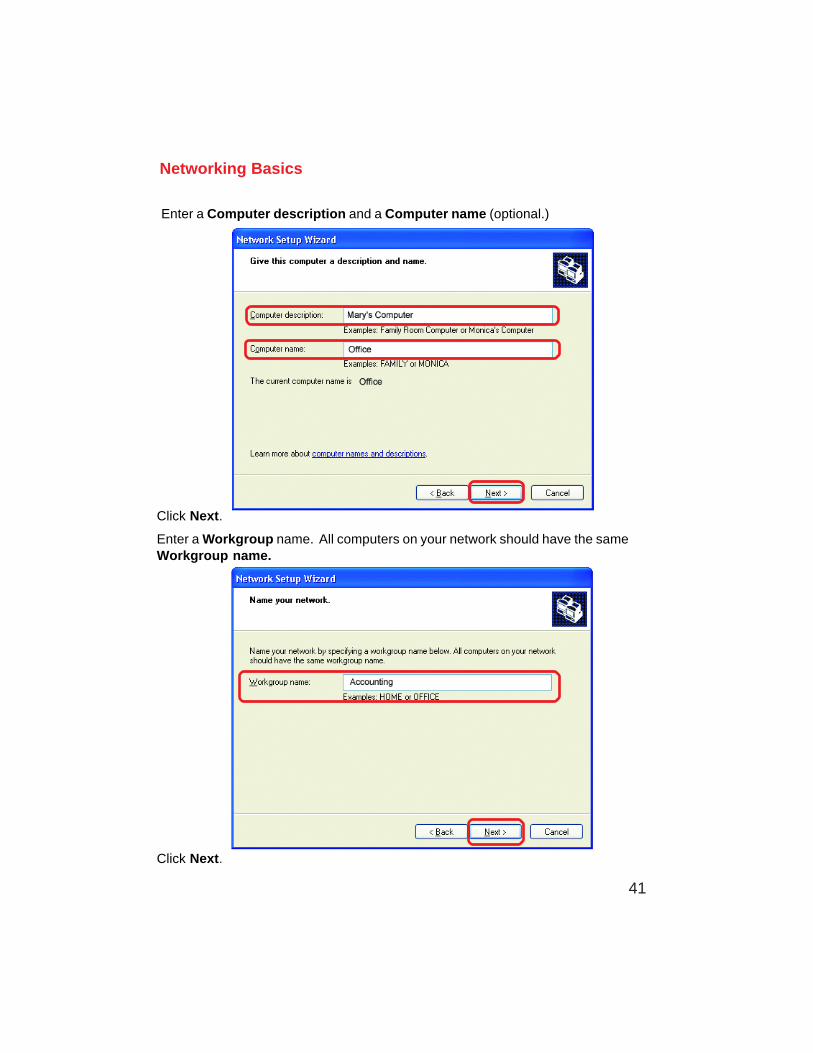
Enter a Computer description and a Computer name (optional.)
Networking Basics
Click Next.
Enter a Workgroup name. All computers on your network should have the sameWorkgroup name.
Click Next.
42
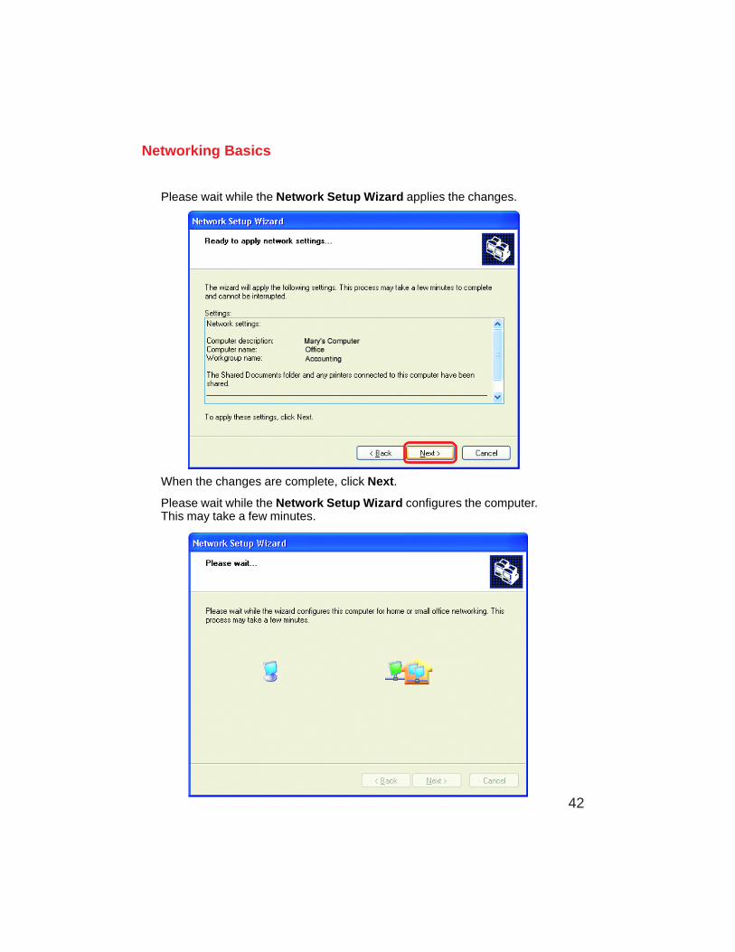
Please wait while the Network Setup Wizard applies the changes.
Networking Basics
When the changes are complete, click Next.
Please wait while the Network Setup Wizard configures the computer.This may take a few minutes.
43
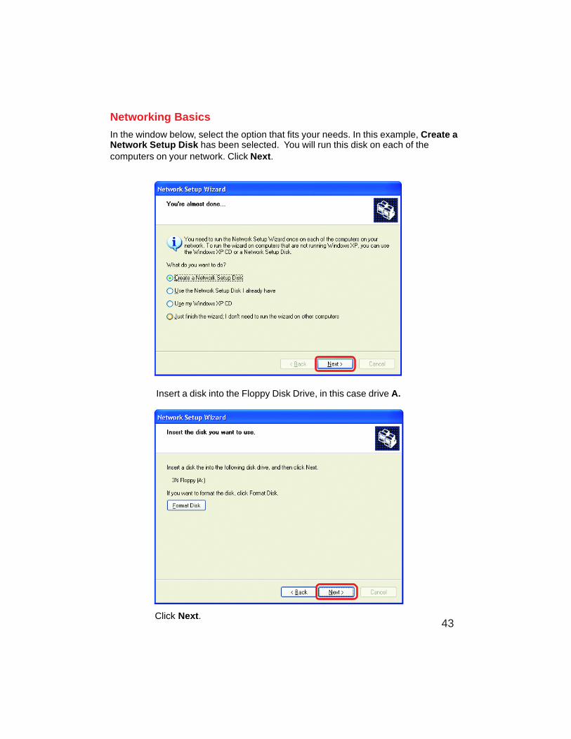
Networking Basics
In the window below, select the option that fits your needs. In this example, Create aNetwork Setup Disk has been selected. You will run this disk on each of thecomputers on your network. Click Next.
Insert a disk into the Floppy Disk Drive, in this case drive A.
Click Next.
44
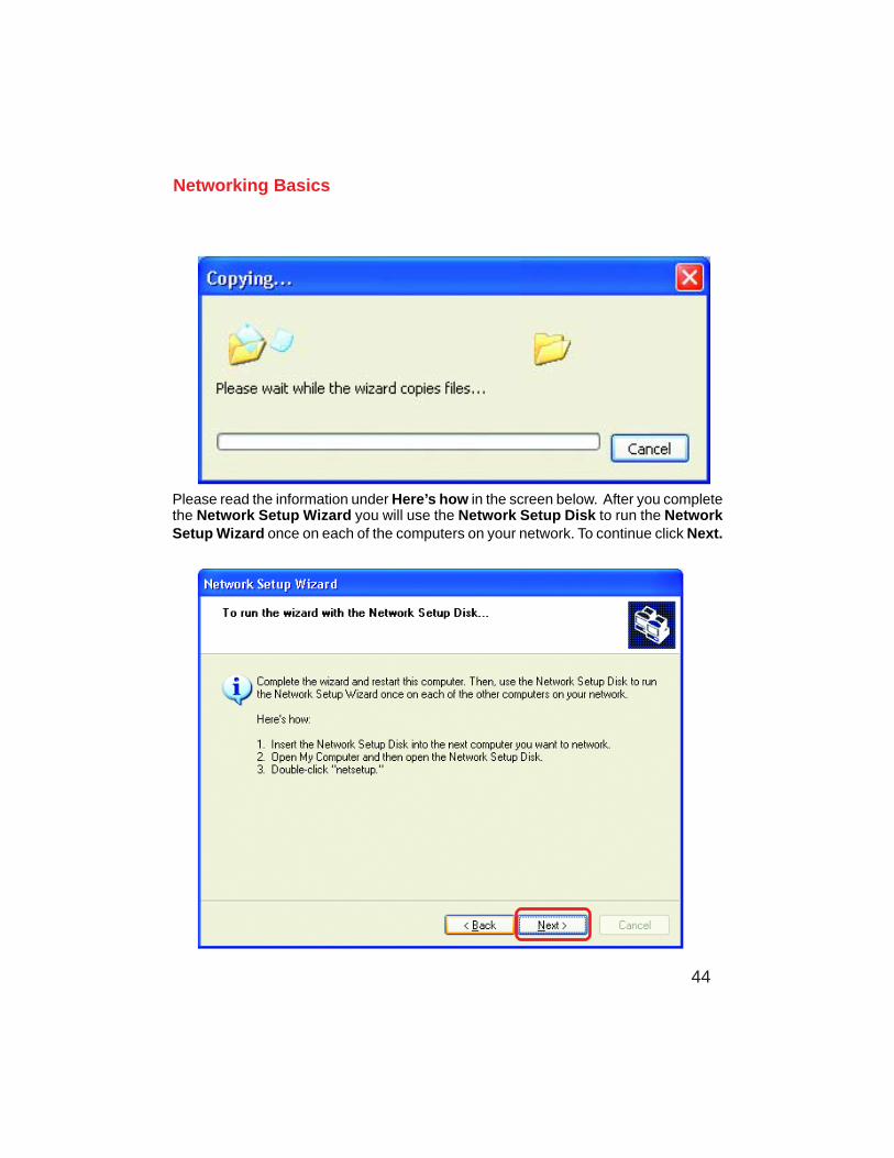
Networking Basics
Please read the information under Here’s how in the screen below. After you completethe Network Setup Wizard you will use the Network Setup Disk to run the NetworkSetup Wizard once on each of the computers on your network. To continue click Next.
45
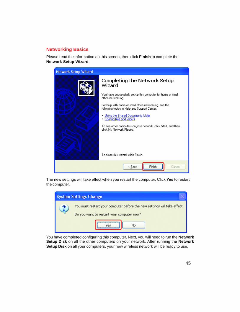
Networking Basics
Please read the information on this screen, then click Finish to complete theNetwork Setup Wizard.
The new settings will take effect when you restart the computer. Click Yes to restartthe computer.
You have completed configuring this computer. Next, you will need to run the NetworkSetup Disk on all the other computers on your network. After running the NetworkSetup Disk on all your computers, your new wireless network will be ready to use.
46
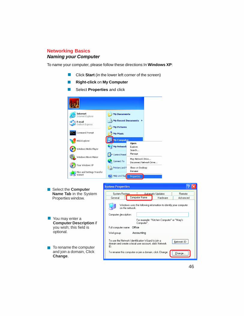
Networking BasicsNaming your Computer
To name your computer, please follow these directions:In Windows XP:
Click Start (in the lower left corner of the screen)
Right-click on My Computer
Select Properties and click
Select the ComputerName Tab in the SystemProperties window.
You may enter aComputer Description ifyou wish; this field isoptional.
To rename the computerand join a domain, ClickChange.
47
Networking BasicsNaming your Computer
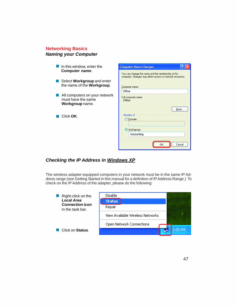
In this window, enter theComputer name.
Select Workgroup and enterthe name of the Workgroup.
All computers on your networkmust have the sameWorkgroup name.
Click OK.
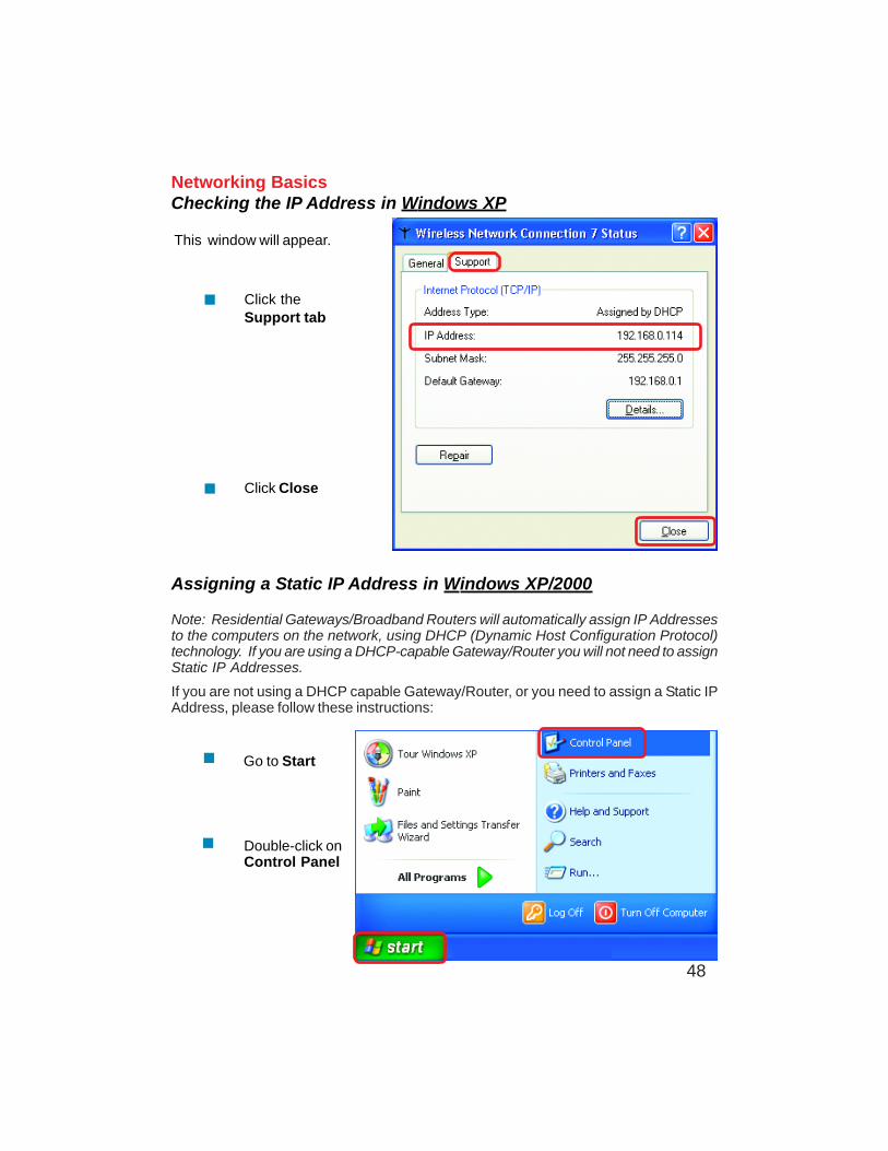
Checking the IP Address in Windows XP
The wireless adapter-equipped computers in your network must be in the same IP Ad-dress range (see Getting Started in this manual for a definition of IP Address Range.) Tocheck on the IP Address of the adapter, please do the following:
Right-click on theLocal AreaConnection iconin the task bar.
Click on Status.
48
Networking BasicsChecking the IP Address in Windows XP
This window will appear.
Click theSupport tab
Click Close
Assigning a Static IP Address in Windows XP/2000
Note: Residential Gateways/Broadband Routers will automatically assign IP Addressesto the computers on the network, using DHCP (Dynamic Host Configuration Protocol)technology. If you are using a DHCP-capable Gateway/Router you will not need to assignStatic IP Addresses.
If you are not using a DHCP capable Gateway/Router, or you need to assign a Static IPAddress, please follow these instructions:
Go to Start
Double-click onControl Panel
49
Networking BasicsAssigning a Static IP Address in Windows XP/2000
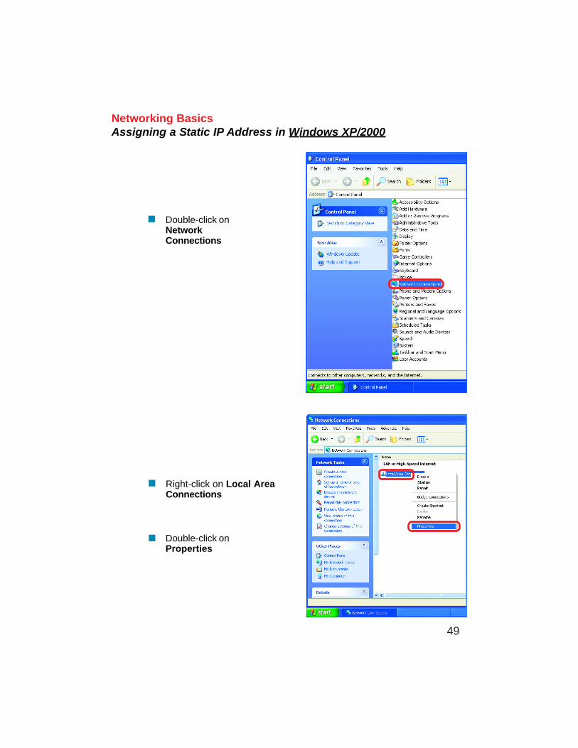
Double-click onNetworkConnections
Double-click onProperties
Right-click on Local AreaConnections
50
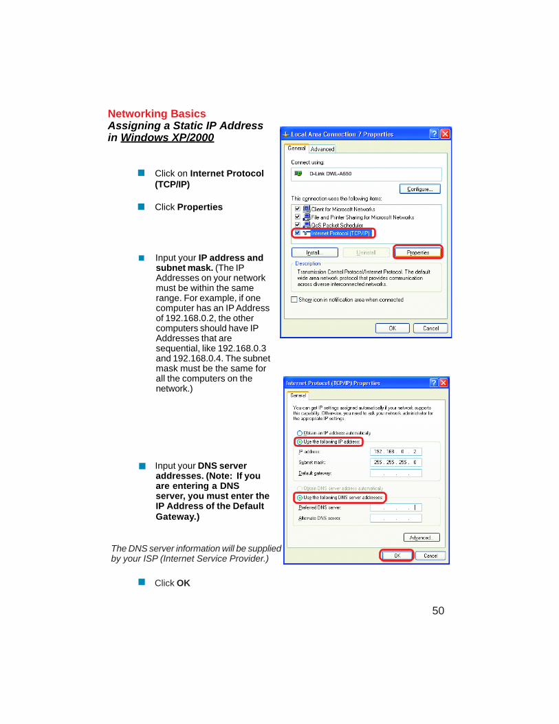
Input your IP address andsubnet mask. (The IPAddresses on your networkmust be within the samerange. For example, if onecomputer has an IP Addressof 192.168.0.2, the othercomputers should have IPAddresses that aresequential, like 192.168.0.3and 192.168.0.4. The subnetmask must be the same forall the computers on thenetwork.)
Networking BasicsAssigning a Static IP Addressin Windows XP/2000
Input your DNS serveraddresses. (Note: If youare entering a DNSserver, you must enter theIP Address of the DefaultGateway.)
The DNS server information will be suppliedby your ISP (Internet Service Provider.)
Click OK
Click on Internet Protocol(TCP/IP)
Click Properties
51
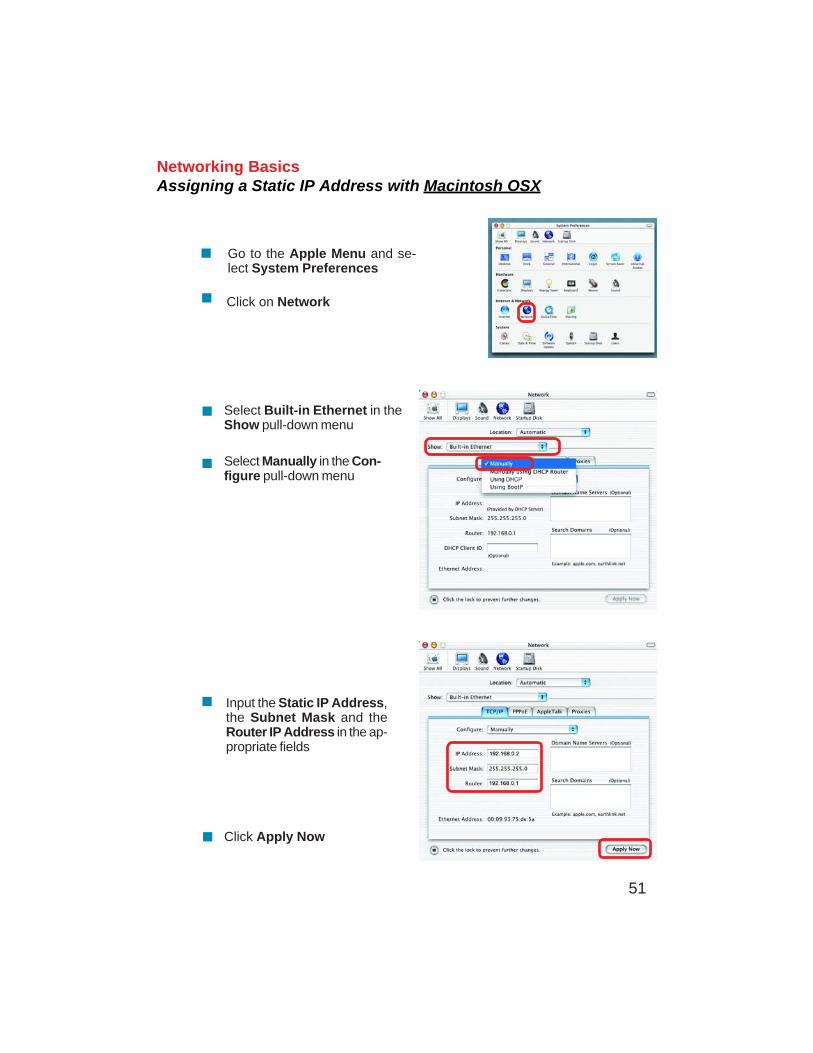
Networking BasicsAssigning a Static IP Address with Macintosh OSX
Go to the Apple Menu and se-lect System Preferences
cClick on Network
Select Built-in Ethernet in theShow pull-down menu
Select Manually in the Con-figure pull-down menu
Input the Static IP Address,the Subnet Mask and theRouter IP Address in the ap-propriate fields
Click Apply Now
52
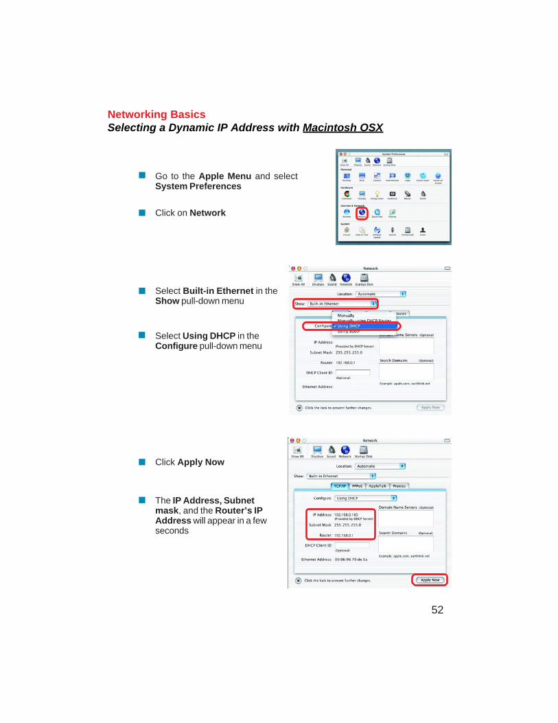
Networking BasicsSelecting a Dynamic IP Address with Macintosh OSX
Go to the Apple Menu and selectSystem Preferences
Click on Network
Select Built-in Ethernet in theShow pull-down menu
Select Using DHCP in theConfigure pull-down menu
Click Apply Now
The IP Address, Subnetmask, and the Router’s IPAddress will appear in a fewseconds
53
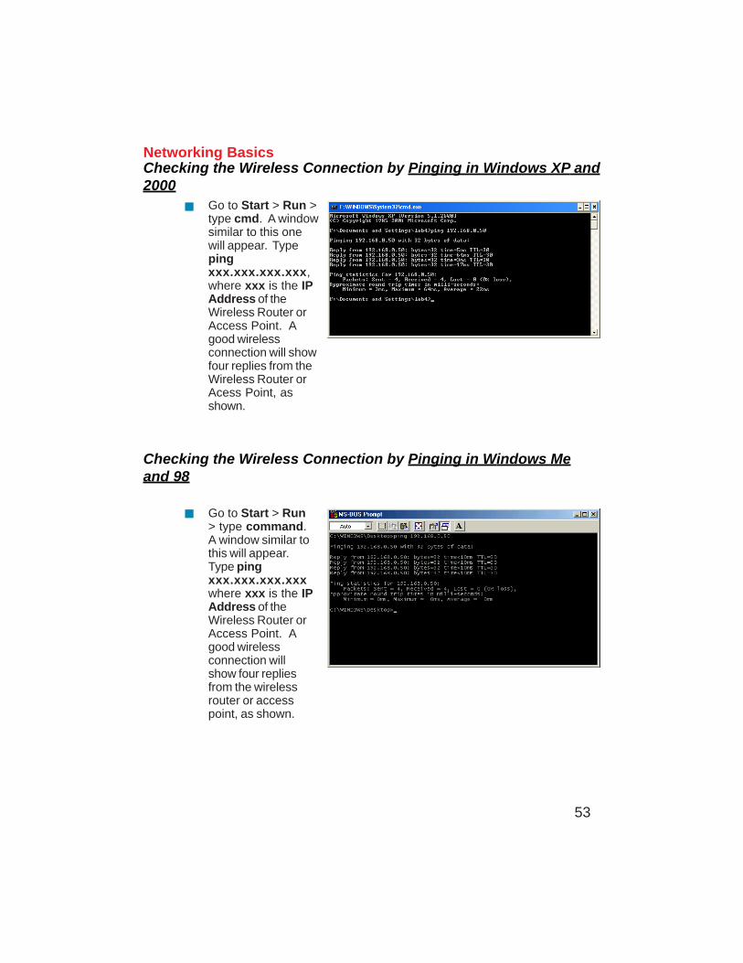
Networking BasicsChecking the Wireless Connection by Pinging in Windows XP and2000
Checking the Wireless Connection by Pinging in Windows Meand 98
Go to Start > Run >type cmd. A windowsimilar to this onewill appear. Typepingxxx.xxx.xxx.xxx,where xxx is the IPAddress of theWireless Router orAccess Point. Agood wirelessconnection will showfour replies from theWireless Router orAcess Point, asshown.
Go to Start > Run> type command.A window similar tothis will appear.Type pingxxx.xxx.xxx.xxxwhere xxx is the IPAddress of theWireless Router orAccess Point. Agood wirelessconnection willshow four repliesfrom the wirelessrouter or accesspoint, as shown.
54
TroubleshootingThis Chapter provides solutions to problems that can occur during the installation andoperation of the VDI-624 Wireless Broadband Router. We cover various aspects of thenetwork setup, including the network adapters. Please read the following if you are havingproblems.
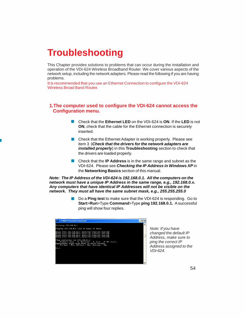
Note: If you havechanged the default IPAddress, make sure toping the correct IPAddress assigned to theVDI-624.
1.The computer used to configure the VDI-624 cannot access the Configuration menu.
Check that the Ethernet LED on the VDI-624 is ON. If the LED is notON, check that the cable for the Ethernet connection is securelyinserted.
Check that the Ethernet Adapter is working properly. Please seeitem 3 (Check that the drivers for the network adapters areinstalled properly) in this Troubleshooting section to check thatthe drivers are loaded properly.
Check that the IP Address is in the same range and subnet as theVDI-624. Please see Checking the IP Address in Windows XP inthe Networking Basics section of this manual.
Note: The IP Address of the VDI-624 is 192.168.0.1. All the computers on thenetwork must have a unique IP Address in the same range, e.g., 192.168.0.x.Any computers that have identical IP Addresses will not be visible on thenetwork. They must all have the same subnet mask, e.g., 255.255.255.0
Do a Ping test to make sure that the VDI-624 is responding. Go toStart>Run>Type Command>Type ping 192.168.0.1. A successfulping will show four replies.
It is recommended that you use an Ethernet Connection to configure the VDI-624Wireless Broad Band Router.
55
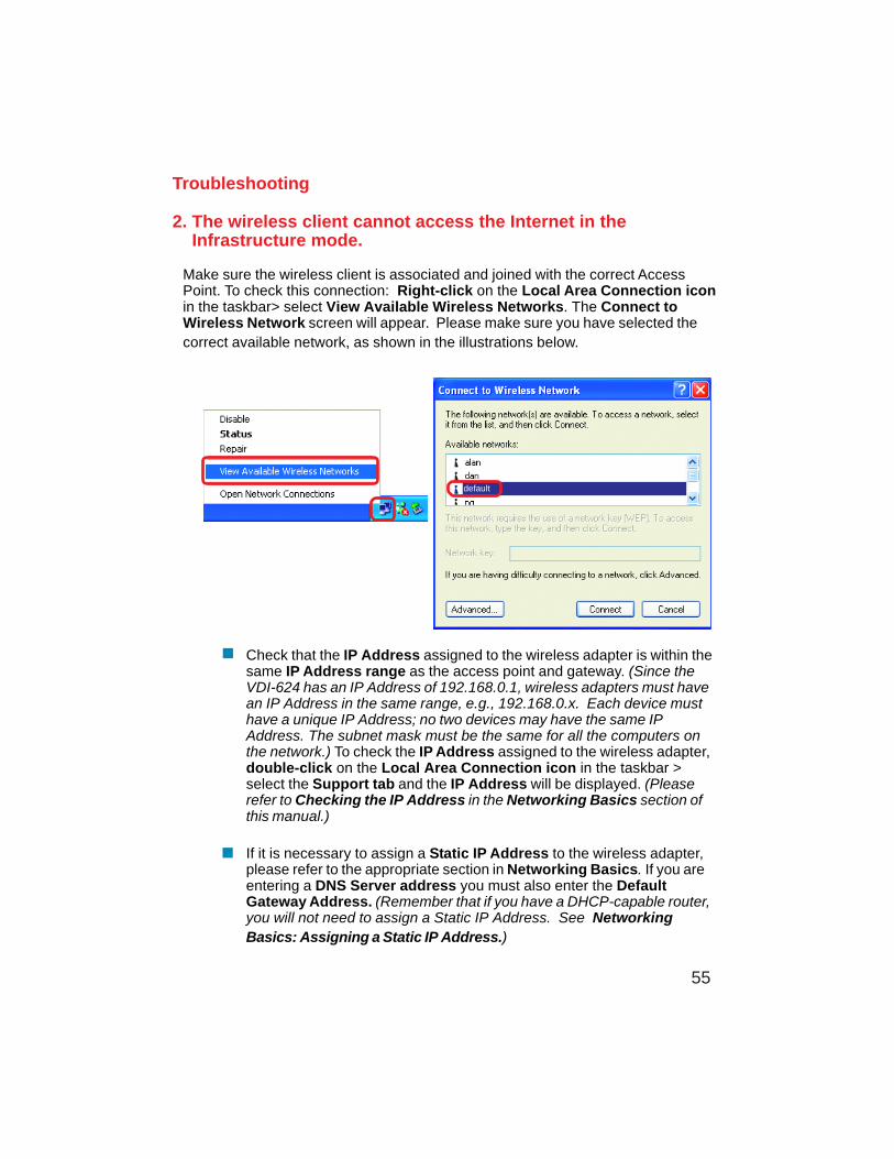
2. The wireless client cannot access the Internet in the Infrastructure mode.
Make sure the wireless client is associated and joined with the correct AccessPoint. To check this connection: Right-click on the Local Area Connection iconin the taskbar> select View Available Wireless Networks. The Connect toWireless Network screen will appear. Please make sure you have selected thecorrect available network, as shown in the illustrations below.
Troubleshooting
Check that the IP Address assigned to the wireless adapter is within thesame IP Address range as the access point and gateway. (Since theVDI-624 has an IP Address of 192.168.0.1, wireless adapters must havean IP Address in the same range, e.g., 192.168.0.x. Each device musthave a unique IP Address; no two devices may have the same IPAddress. The subnet mask must be the same for all the computers onthe network.) To check the IP Address assigned to the wireless adapter,double-click on the Local Area Connection icon in the taskbar >select the Support tab and the IP Address will be displayed. (Pleaserefer to Checking the IP Address in the Networking Basics section ofthis manual.)
If it is necessary to assign a Static IP Address to the wireless adapter,please refer to the appropriate section in Networking Basics. If you areentering a DNS Server address you must also enter the DefaultGateway Address. (Remember that if you have a DHCP-capable router,you will not need to assign a Static IP Address. See NetworkingBasics: Assigning a Static IP Address.)
default
56
Troubleshooting
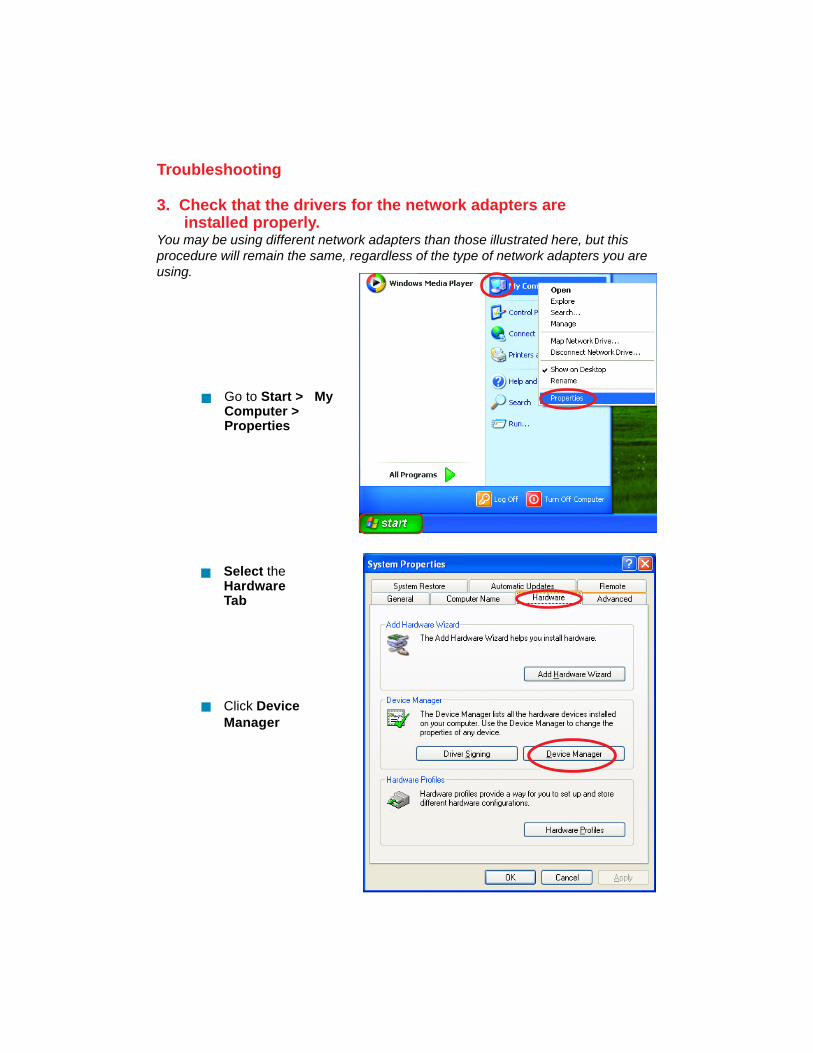
3. Check that the drivers for the network adapters are installed properly.You may be using different network adapters than those illustrated here, but thisprocedure will remain the same, regardless of the type of network adapters you areusing.
Click DeviceManager
Select theHardwareTab
Go to Start > MyComputer >Properties
57
Troubleshooting
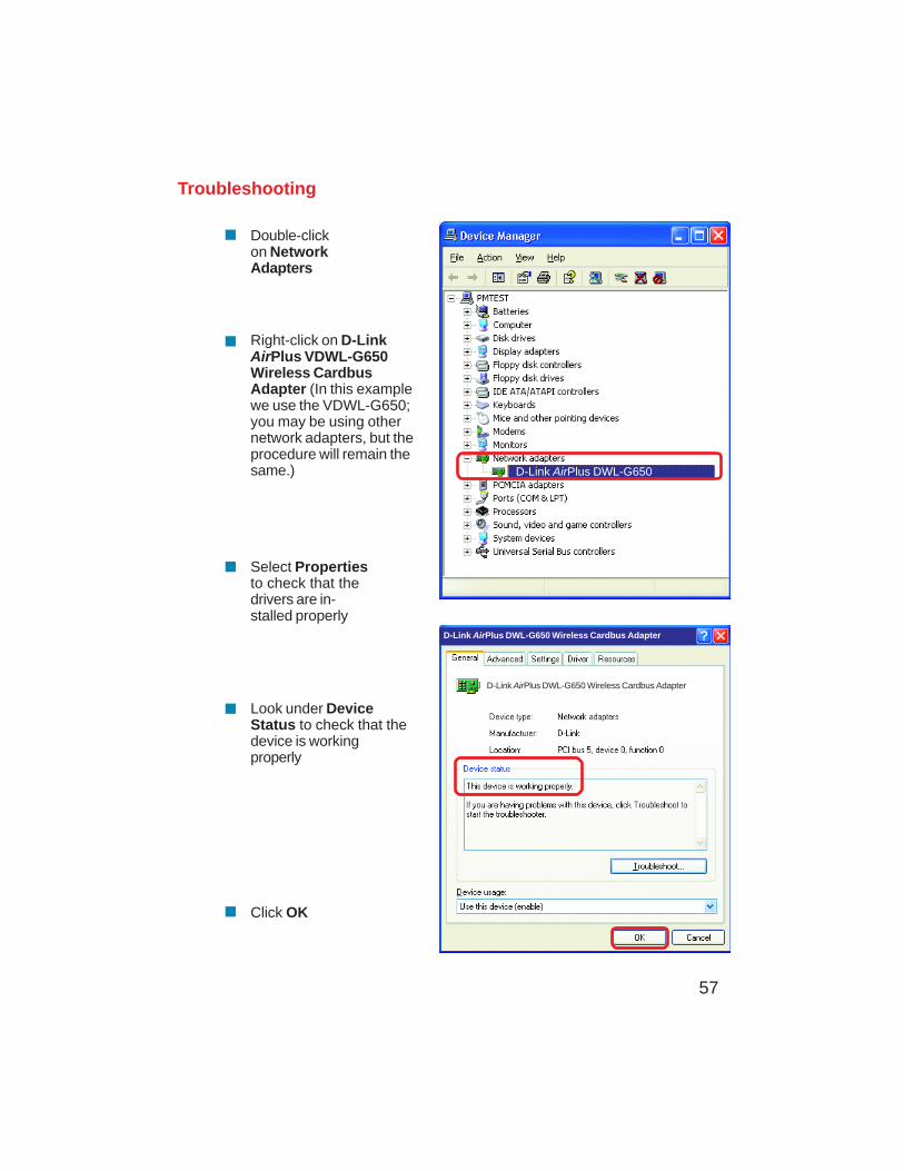
Double-clickon NetworkAdapters
Right-click on D-LinkAirPlus VDWL-G650Wireless CardbusAdapter (In this examplewe use the VDWL-G650;you may be using othernetwork adapters, but theprocedure will remain thesame.)
Select Propertiesto check that thedrivers are in-stalled properly
Look under DeviceStatus to check that thedevice is workingproperly
Click OK
D-Link AirPlus DWL-G650
D-Link AirPlus DWL-G650 Wireless Cardbus Adapter
D-Link AirPlus DWL-G650 Wireless Cardbus Adapter
58
Troubleshooting
4. What variables may cause my wireless products to lose reception?
D-Link products let you access your network from virtually anywhere you want. However,the positioning of the products within your environment will affect the wireless range.Please refer to Installation Considerations in the Wireless Basics section of this manualfor further information about the most advantageous placement of your D-Link wirelessproducts.
5. Why does my wireless connection keep dropping?
6. Why can’t I get a wireless connection?
If you have enabled Encryption on the VDI-624, you must also enable encryption on allwireless clients in order to establish a wireless connection.
Make sure that the SSID on the Router and the Wireless Client are exactly thesame. If they are not, wireless connection will not be established.
For 802.11g, the Encryption settings are: 64 or 128 bit. Make sure that theencryption bit level is the same on the Router and the Wireless Client.
Move the VDI-624 and the wireless client into the same room and then test thewireless connection.
Disable all security settings. (WEP, MAC Address Control)
Antenna Orientation- Try different antenna orientations for the VDI-624. Try tokeep the antenna at least 6 inches away from the wall or other objects.
If you are using 2.4GHz cordless phones, X-10 equipment or other home secu-rity systems, ceiling fans, and lights, your wireless connection will degrade dra-matically or drop altogether. Try changing the Channel on your Router, AccessPoint and Wireless adapter to a different Channel to avoid interference.
Keep your product away (at least 3-6 feet) from electrical devices that generateRF noise, like microwaves, monitors, electric motors, etc.
59
Troubleshooting
6. Why can’t I get a wireless connection? (continued)
Turn off your VDI-624 and the client. Turn the VDI-624 back on again, and thenturn on the client.
Check that the LED indicators are indicating normal activity. If not, check that theAC power and Ethernet cables are firmly connected.
Make sure that all devices are set to Infrastructure mode.
Check that the IP Address, subnet mask, gateway and DNS settings are cor-rectly entered for the network.
If you are using 2.4GHz cordless phones, X-10 equipment or other home securitysystems, ceiling fans, and lights, your wireless connection will degrade dramati-cally or drop altogether. Try changing the Channel on your VDI-624, and on all thedevices in your network to avoid interference.
Keep your product away (at least 3-6 feet) from electrical devices that generateRF noise, like microwaves, monitors, electric motors, etc.
7. I forgot my encryption key.
Reset the VDI-624 to its factory default settings and restore the other devices onyour network to their default settings. You may do this by pressing the Resetbutton on the back of the unit. You will lose the current configuration settings.
60
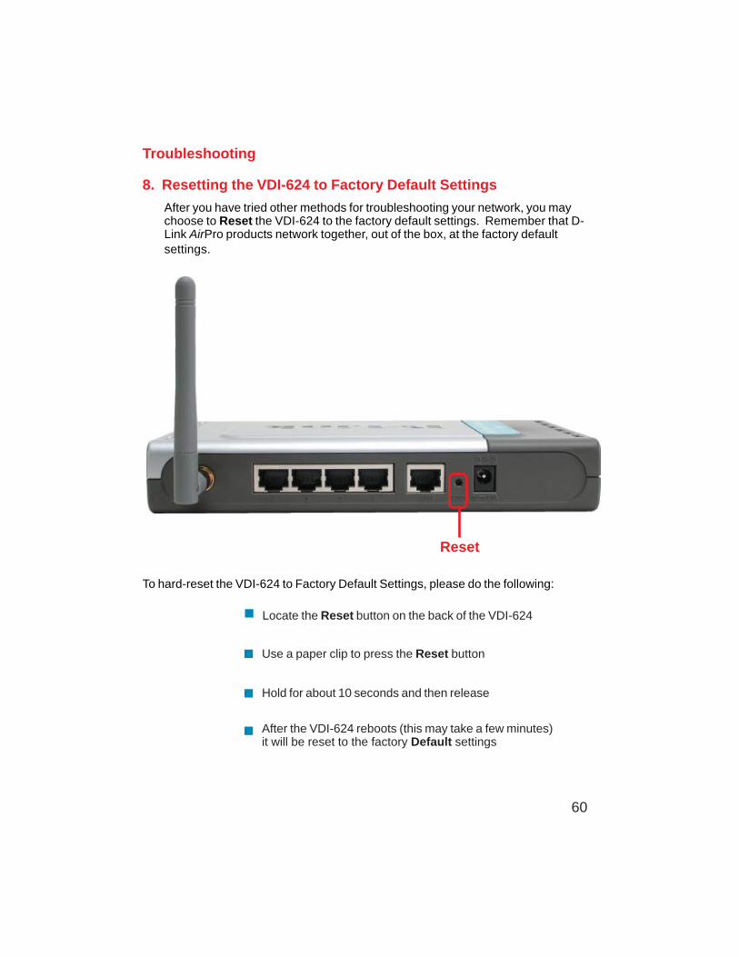
8. Resetting the VDI-624 to Factory Default Settings
After you have tried other methods for troubleshooting your network, you maychoose to Reset the VDI-624 to the factory default settings. Remember that D-Link AirPro products network together, out of the box, at the factory defaultsettings.
To hard-reset the VDI-624 to Factory Default Settings, please do the following:
Troubleshooting
After the VDI-624 reboots (this may take a few minutes)it will be reset to the factory Default settings
Use a paper clip to press the Reset button
Hold for about 10 seconds and then release
Locate the Reset button on the back of the VDI-624
Reset
61
IP FilteringURL FilteringDomain BlockingScheduling
IEEE 802.11bIEEE 802.3IEEE 802.3u
Technical Specifications
L2TP
Standards
VPN Pass Through/ Multi-SessionsPPTP
Device Management
Web-Based- Internet Explorer v6 or later; Netscape Navigator v6or later; or other Java-enabled browsers
Advanced Firewall Features
NAT with VPN Passthrough (Network Address Translation)
95% maximum (non-condensing)
Wireless Operating Range
Operating Temperature 32ºF to 131ºF (0ºC to 55ºC)
Humidity:
Indoors – up to 328 feet (100 meters)
IPSec
DHCP Server and Client
MAC Filtering
Outdoors – up to 1312 feet (400 meters)
Safety and Emissions:
FCC
IEEE 802.11g
2.4GHz to 2.462GHz
Wireless Frequency Range:
62
LEDs:PowerWAN
Physical Dimensions:
Technical Specifications
L = 7.56 inches (192mm)W = 4.65 inches (118mm)H = 1.22 inches (31mm)
Wireless Transmit Power:
15dBm ± 2dB
Security:
802.1xWPA- WiFi Protected Access(64-,128-WEP with TKIP, MIC, IV Expansion, Shared KeyAuthentication)
External Antenna Type:
Single detachable reverse SMA
Orthogonal Frequency Division Multiplexing (OFDM)
Modulation Technology:
Power Input:
Ext. Power Supply DC 5V, 2.5A
Weight:
10.8 oz. (0.3kg)
LAN (10/100)WLAN (Wireless Connection)
63
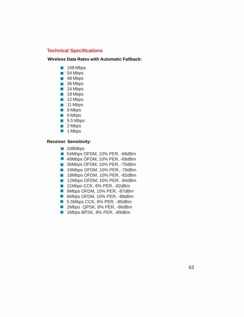
108 Mbps54 Mbps48 Mbps36 Mbps24 Mbps18 Mbps12 Mbps11 Mbps9 Mbps6 Mbps5.5 Mbps2 Mbps1 Mbps
Wireless Data Rates with Automatic Fallback:
108Mbps54Mbps OFDM, 10% PER, -68dBm48Mbps OFDM, 10% PER, -68dBm36Mbps OFDM, 10% PER, -75dBm
Receiver Sensitivity:
24Mbps OFDM, 10% PER, -79dBm18Mbps OFDM, 10% PER, -82dBm12Mbps OFDM, 10% PER, -84dBm11Mbps CCK, 8% PER, -82dBm9Mbps OFDM, 10% PER, -87dBm6Mbps OFDM, 10% PER, -88dBm5.5Mbps CCK, 8% PER, -85dBm2Mbps QPSK, 8% PER, -86dBm1Mbps BPSK, 8% PER, -89dBm
Technical Specifications
64
Frequently Asked Questions
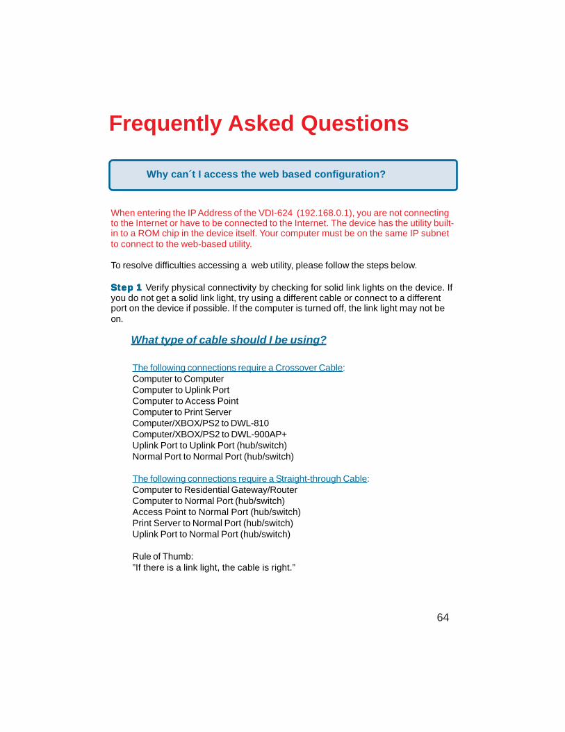
When entering the IP Address of the VDI-624 (192.168.0.1), you are not connectingto the Internet or have to be connected to the Internet. The device has the utility built-in to a ROM chip in the device itself. Your computer must be on the same IP subnetto connect to the web-based utility.
To resolve difficulties accessing a web utility, please follow the steps below.
SteSteSteSteStep 1p 1p 1p 1p 1 Verify physical connectivity by checking for solid link lights on the device. Ifyou do not get a solid link light, try using a different cable or connect to a differentport on the device if possible. If the computer is turned off, the link light may not beon.
The following connections require a Crossover Cable:Computer to ComputerComputer to Uplink PortComputer to Access PointComputer to Print ServerComputer/XBOX/PS2 to DWL-810Computer/XBOX/PS2 to DWL-900AP+Uplink Port to Uplink Port (hub/switch)Normal Port to Normal Port (hub/switch)
The following connections require a Straight-through Cable:Computer to Residential Gateway/RouterComputer to Normal Port (hub/switch)Access Point to Normal Port (hub/switch)Print Server to Normal Port (hub/switch)Uplink Port to Normal Port (hub/switch)
Rule of Thumb:”If there is a link light, the cable is right.”
What type of cable should I be using?
Why can´t I access the web based configuration?
65
Frequently Asked Questions (continued)
What type of cable should I be using? (continued)
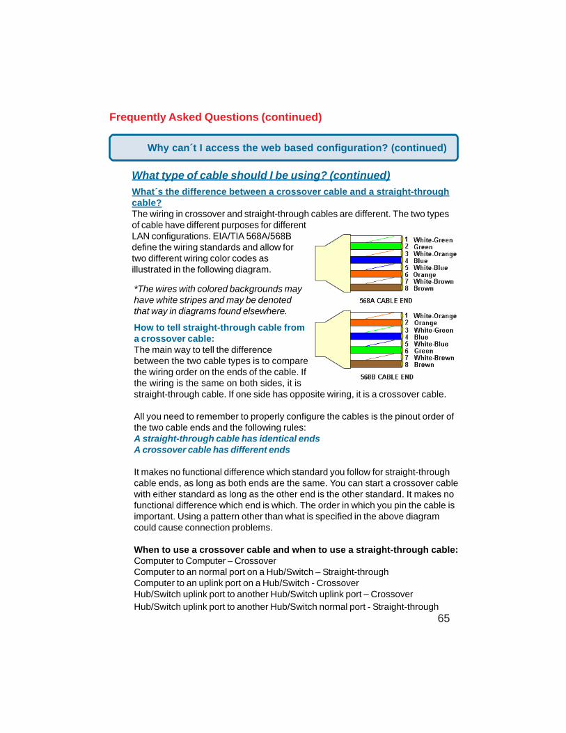
What´s the difference between a crossover cable and a straight-throughcable?The wiring in crossover and straight-through cables are different. The two typesof cable have different purposes for differentLAN configurations. EIA/TIA 568A/568Bdefine the wiring standards and allow fortwo different wiring color codes asillustrated in the following diagram.
*The wires with colored backgrounds mayhave white stripes and may be denotedthat way in diagrams found elsewhere.
How to tell straight-through cable froma crossover cable:The main way to tell the differencebetween the two cable types is to comparethe wiring order on the ends of the cable. Ifthe wiring is the same on both sides, it isstraight-through cable. If one side has opposite wiring, it is a crossover cable.
All you need to remember to properly configure the cables is the pinout order ofthe two cable ends and the following rules:A straight-through cable has identical endsA crossover cable has different ends
It makes no functional difference which standard you follow for straight-throughcable ends, as long as both ends are the same. You can start a crossover cablewith either standard as long as the other end is the other standard. It makes nofunctional difference which end is which. The order in which you pin the cable isimportant. Using a pattern other than what is specified in the above diagramcould cause connection problems.
When to use a crossover cable and when to use a straight-through cable:Computer to Computer – CrossoverComputer to an normal port on a Hub/Switch – Straight-throughComputer to an uplink port on a Hub/Switch - CrossoverHub/Switch uplink port to another Hub/Switch uplink port – CrossoverHub/Switch uplink port to another Hub/Switch normal port - Straight-through
Why can´t I access the web based configuration? (continued)
66
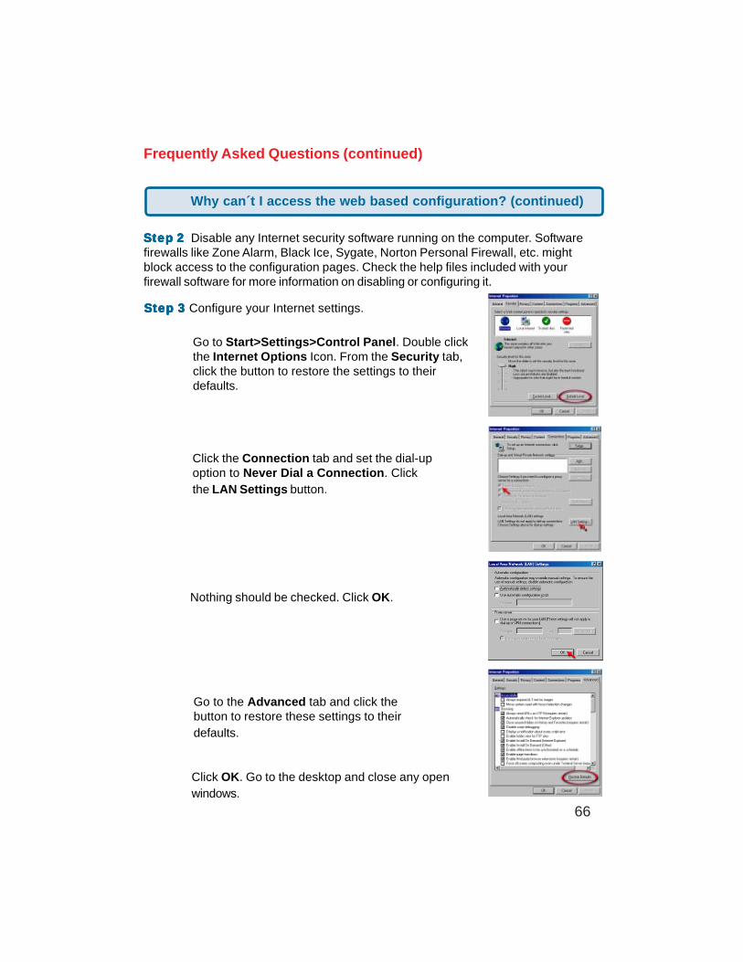
Step 3Step 3Step 3Step 3Step 3 Configure your Internet settings.
SteSteSteSteStep 2p 2p 2p 2p 2 Disable any Internet security software running on the computer. Softwarefirewalls like Zone Alarm, Black Ice, Sygate, Norton Personal Firewall, etc. mightblock access to the configuration pages. Check the help files included with yourfirewall software for more information on disabling or configuring it.
Frequently Asked Questions (continued)
Click the Connection tab and set the dial-upoption to Never Dial a Connection. Clickthe LAN Settings button.
Nothing should be checked. Click OK.
Go to the Advanced tab and click thebutton to restore these settings to theirdefaults.
Click OK. Go to the desktop and close any openwindows.
Go to Start>Settings>Control Panel. Double clickthe Internet Options Icon. From the Security tab,click the button to restore the settings to theirdefaults.
Why can´t I access the web based configuration? (continued)
67
Frequently Asked Questions (continued)
SteSteSteSteStep 4p 4p 4p 4p 4 Check your IP Address. Your computer must have an IP Address in thesame range of the device you are attempting to configure. Most D-Link devices usethe 192.168.0.X range.
How can I find my IP Address in Windows 95, 98, orME?
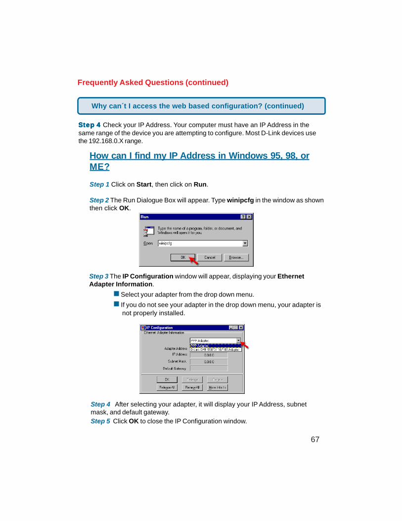
Step 1 Click on Start, then click on Run.
Step 2 The Run Dialogue Box will appear. Type winipcfg in the window as shownthen click OK.
Step 3 The IP Configuration window will appear, displaying your EthernetAdapter Information.
Select your adapter from the drop down menu.
If you do not see your adapter in the drop down menu, your adapter is not properly installed.
Step 4 After selecting your adapter, it will display your IP Address, subnetmask, and default gateway.Step 5 Click OK to close the IP Configuration window.
Why can´t I access the web based configuration? (continued)
68
Frequently Asked Questions (continued)
SteSteSteSteStep 4p 4p 4p 4p 4 (continued) Check your IP Address. Your computer must have an IP Addressin the same range of the device you are attempting to configure. Most D-Link devicesuse the 192.168.0.X range.
How can I find my IP Address in Windows 2000/XP?
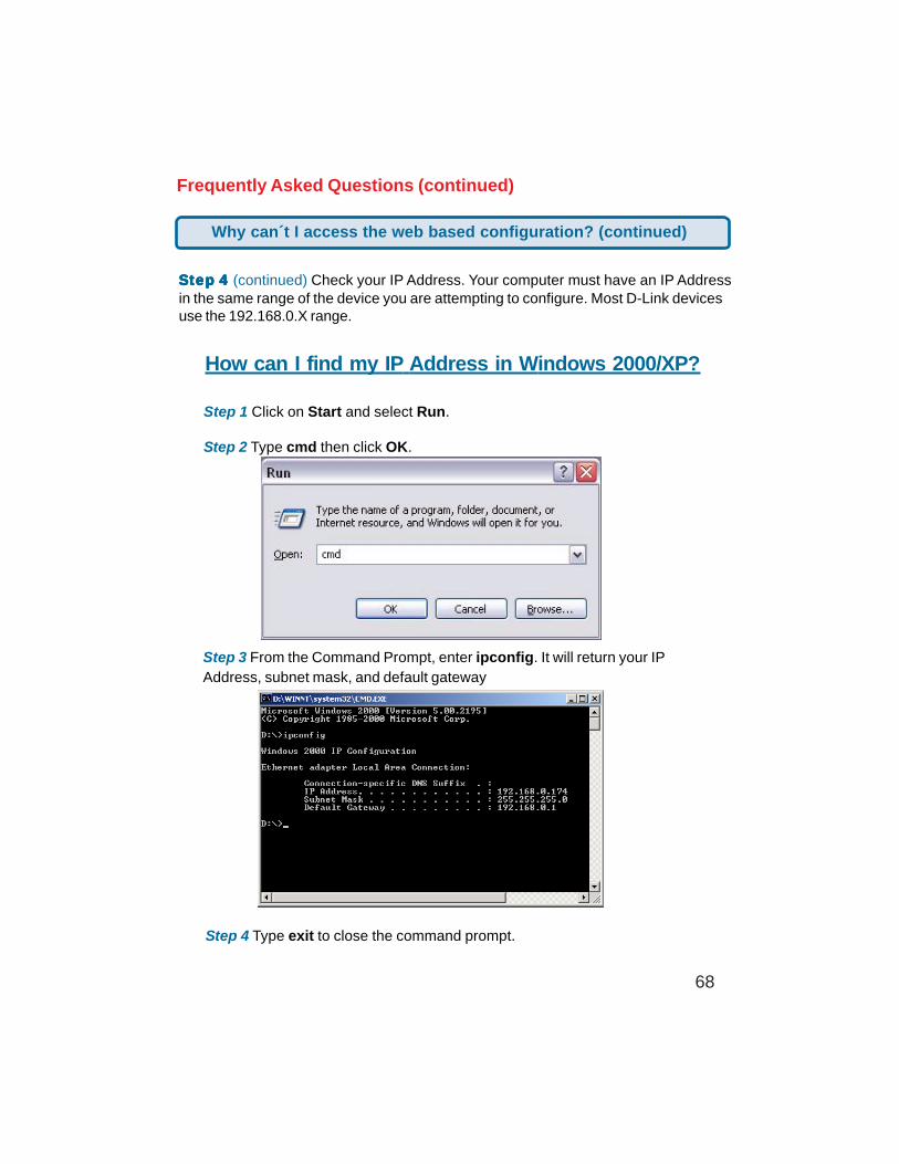
Step 1 Click on Start and select Run.
Step 2 Type cmd then click OK.
Step 3 From the Command Prompt, enter ipconfig. It will return your IPAddress, subnet mask, and default gateway
Step 4 Type exit to close the command prompt.
Why can´t I access the web based configuration? (continued)
69
Frequently Asked Questions (continued)
SteSteSteSteStep 4p 4p 4p 4p 4 (continued) Check your IP Address. Your computer must have an IPAddress in the same range of the device you are attempting to configure. Most D-Linkdevices use the 192.168.0.X range.
Make sure you take note of your computer´s Default Gateway IP Address. The DefaultGateway is the IP Address of the D-Link router. By default, it should be 192.168.0.1.
How can I assign a Static IP Address in Windows XP?Step 1Click on Start > Control Panel > Network and Internet Connections >Network connections.
Step 2 See Step 2 for Windows 2000 and continue from there.
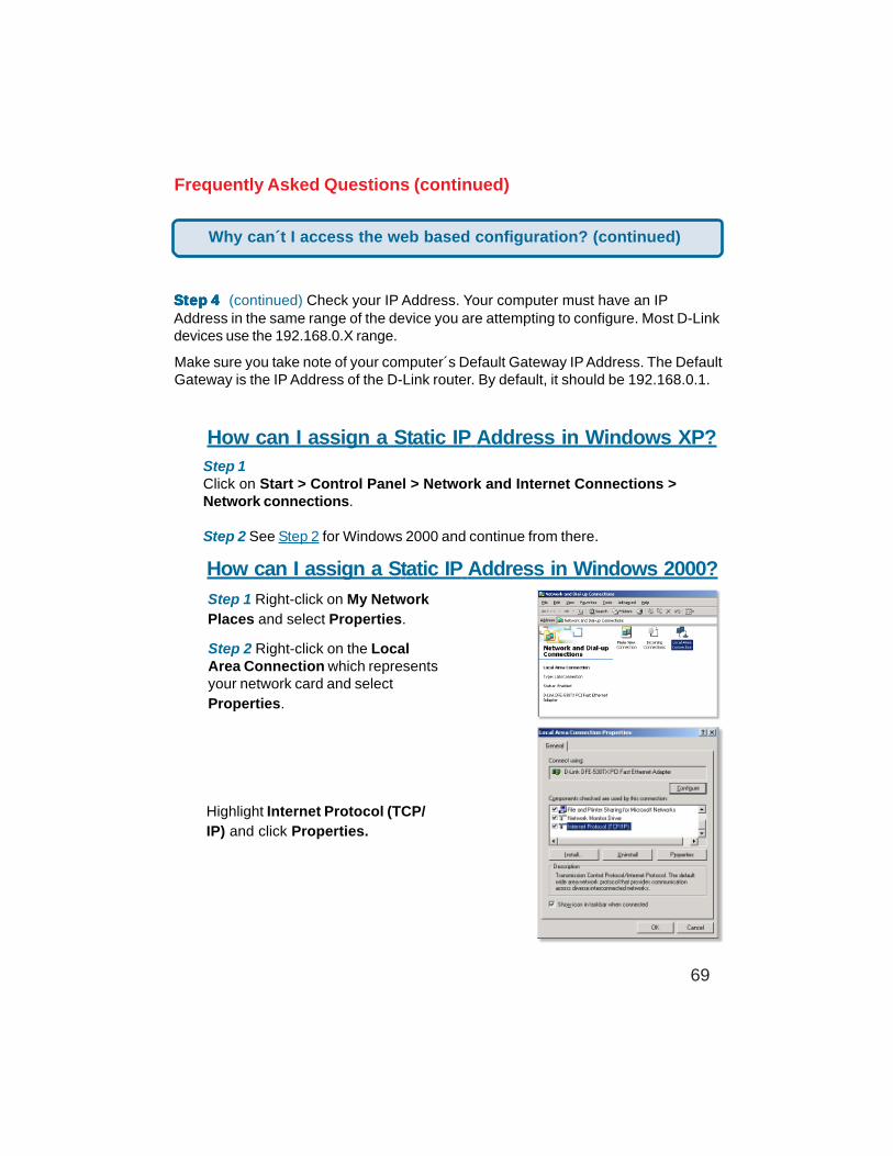
How can I assign a Static IP Address in Windows 2000?
Step 1 Right-click on My NetworkPlaces and select Properties.
Step 2 Right-click on the LocalArea Connection which representsyour network card and selectProperties.
Highlight Internet Protocol (TCP/IP) and click Properties.
Why can´t I access the web based configuration? (continued)
70
Frequently Asked Questions (continued)
How can I assign a Static IP Address in Windows 2000?(continued)
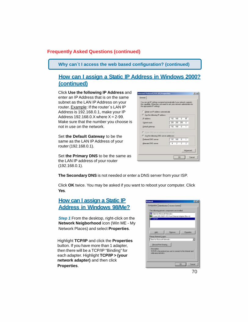
Click Use the following IP Address andenter an IP Address that is on the samesubnet as the LAN IP Address on yourrouter. Example: If the router´s LAN IPAddress is 192.168.0.1, make your IPAddress 192.168.0.X where X = 2-99.Make sure that the number you choose isnot in use on the network.
Set the Default Gateway to be thesame as the LAN IP Address of yourrouter (192.168.0.1).
Set the Primary DNS to be the same asthe LAN IP address of your router(192.168.0.1).
The Secondary DNS is not needed or enter a DNS server from your ISP.
Click OK twice. You may be asked if you want to reboot your computer. ClickYes.
How can I assign a Static IPAddress in Windows 98/Me?
Step 1 From the desktop, right-click on theNetwork Neigborhood icon (Win ME - MyNetwork Places) and select Properties.
Highlight TCP/IP and click the Propertiesbutton. If you have more than 1 adapter,then there will be a TCP/IP “Binding” foreach adapter. Highlight TCP/IP > (yournetwork adapter) and then clickProperties.
Why can´t I access the web based configuration? (continued)
71
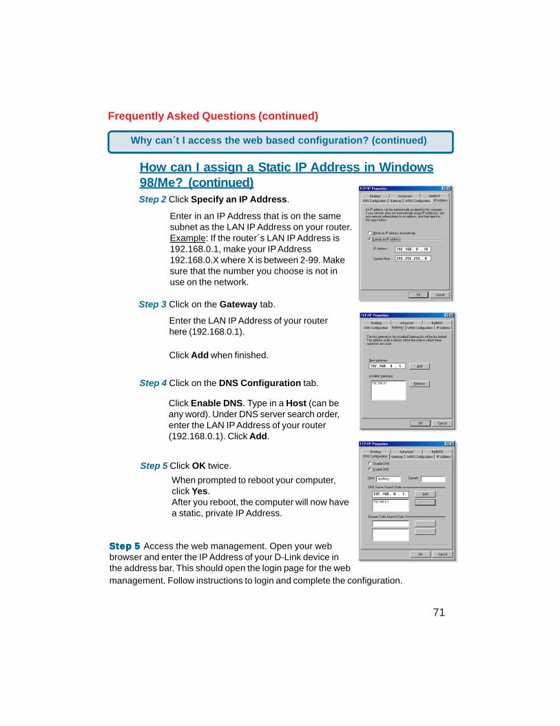
Frequently Asked Questions (continued)
How can I assign a Static IP Address in Windows98/Me? (continued)Step 2 Click Specify an IP Address.
Step 3 Click on the Gateway tab.
Enter the LAN IP Address of your routerhere (192.168.0.1).
Click Add when finished.
Step 4 Click on the DNS Configuration tab.
Enter in an IP Address that is on the samesubnet as the LAN IP Address on your router.Example: If the router´s LAN IP Address is192.168.0.1, make your IP Address192.168.0.X where X is between 2-99. Makesure that the number you choose is not inuse on the network.
Step 5 Click OK twice.
Click Enable DNS. Type in a Host (can beany word). Under DNS server search order,enter the LAN IP Address of your router(192.168.0.1). Click Add.
When prompted to reboot your computer,click Yes.After you reboot, the computer will now havea static, private IP Address.
Why can´t I access the web based configuration? (continued)
SteSteSteSteStep 5p 5p 5p 5p 5 Access the web management. Open your webbrowser and enter the IP Address of your D-Link device inthe address bar. This should open the login page for the webmanagement. Follow instructions to login and complete the configuration.
72
Frequently Asked Questions (continued)
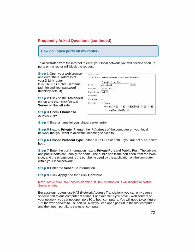
How do I open ports on my router?
To allow traffic from the internet to enter your local network, you will need to open upports or the router will block the request.
Step 1 Open your web browserand enter the IP Address ofyour D-Link router(192.168.0.1). Enter username(admin) and your password(blank by default).
Step 2 Click on the Advancedon top and then click VirtualServer on the left side.
Step 3 Check Enabled toactivate entry.
Step 4 Enter a name for your virtual server entry.
Step 5 Next to Private IP, enter the IP Address of the computer on your localnetwork that you want to allow the incoming service to.
Step 6 Choose Protocol Type - either TCP, UDP, or both. If you are not sure, selectboth.
Step 7 Enter the port information next to Private Port and Public Port. The privateand public ports are usually the same. The public port is the port seen from the WANside, and the private port is the port being used by the application on the computerwithin your local network.
Step 8 Enter the Schedule information.
Step 9 Click Apply and then click Continue.
Note: Make sure DMZ host is disabled. If DMZ is enabled, it will disable all VirtualServer entries.
Because our routers use NAT (Network Address Translation), you can only open aspecific port to one computer at a time. For example: If you have 2 web servers onyour network, you cannot open port 80 to both computers. You will need to configure1 of the web servers to use port 81. Now you can open port 80 to the first computerand then open port 81 to the other computer.
73
Frequently Asked Questions (continued)
What is DMZ?
Demilitarized Zone:In computer networks, a DMZ (demilitarized zone) is a computer host or smallnetwork inserted as a neutral zone between a company´s private network and theoutside public network. It prevents outside users from getting direct access to aserver that has company data. (The term comes from the geographic buffer zone thatwas set up between North Korea and South Korea following the UN police action inthe early 1950s.) A DMZ is an optional and more secure approach to a firewall andeffectively acts as a proxy server as well.
In a typical DMZ configuration for a small company, a separate computer (or host innetwork terms) receives requests from users within the private network for access toWeb sites or other companies accessible on the public network. The DMZ host theninitiates sessions for these requests on the public network. However, the DMZ host isnot able to initiate a session back into the private network. It can only forward packetsthat have already been requested.
Users of the public network outside the company can access only the DMZ host. TheDMZ may typically also have the company´s Web pages so these could be served tothe outside world. However, the DMZ provides access to no other company data. Inthe event that an outside user penetrated the DMZ hosts security, the Web pagesmight be corrupted but no other company information would be exposed. D-Link, aleading maker of routers, is one company that sells products designed for setting upa DMZ.
How do I configure the DMZ Host?
The DMZ feature allows you to forward all incoming ports to one computer on the localnetwork. The DMZ, or Demilitarized Zone, will allow the specified computer to beexposed to the Internet. DMZ is useful when a certain application or game does notwork through the firewall. The computer that is configured for DMZ will be completelyvulnerable on the Internet, so it is suggested that you try opening ports from theVirtual Server or Firewall settings before using DMZ.
Step 1 Find the IP address of the computer you want to use as the DMZ host.
To find out how to locate the IP Address of the computer in Windows XP/2000/ME/9xor Macintosh operating systems please refer to Step 4 of the first question in thissection (Frequently Asked Questions).
74
Frequently Asked Questions (continued)
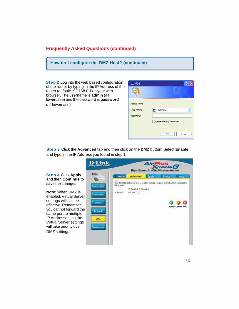
Step 2 Log into the web based configurationof the router by typing in the IP Address of therouter (default:192.168.0.1) in your webbrowser. The username is admin (alllowercase) and the password is password(all lowercase)
How do I configure the DMZ Host? (continued)
Step 3 Click the Advanced tab and then click on the DMZ button. Select Enableand type in the IP Address you found in step 1.
Step 4 Click Applyand then Continue tosave the changes.
Note: When DMZ isenabled, Virtual Serversettings will still beeffective. Remember,you cannot forward thesame port to multipleIP Addresses, so theVirtual Server settingswill take priority overDMZ settings.
DI-624
admin
75
Frequently Asked Questions (continued)
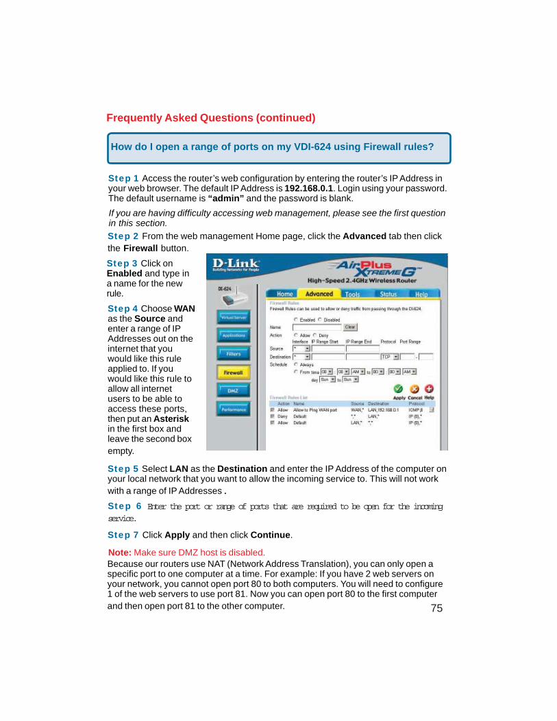
How do I open a range of ports on my VDI-624 using Firewall rules?
Step 1 Access the router’s web configuration by entering the router’s IP Address inyour web browser. The default IP Address is 192.168.0.1. Login using your password.The default username is “admin” and the password is blank.
If you are having difficulty accessing web management, please see the first questionin this section.
Step 2 From the web management Home page, click the Advanced tab then clickthe Firewall button.
Step 3 Click onEnabled and type ina name for the newrule.
Step 4 Choose WANas the Source andenter a range of IPAddresses out on theinternet that youwould like this ruleapplied to. If youwould like this rule toallow all internetusers to be able toaccess these ports,then put an Asteriskin the first box andleave the second boxempty.
Step 5 Select LAN as the Destination and enter the IP Address of the computer onyour local network that you want to allow the incoming service to. This will not workwith a range of IP Addresses.
Step 6 Enter the port or range of ports that are required to be open for the incomingservice.
Step 7 Click Apply and then click Continue.
Because our routers use NAT (Network Address Translation), you can only open aspecific port to one computer at a time. For example: If you have 2 web servers onyour network, you cannot open port 80 to both computers. You will need to configure1 of the web servers to use port 81. Now you can open port 80 to the first computerand then open port 81 to the other computer.
Note: Make sure DMZ host is disabled.
76
Frequently Asked Questions (continued)
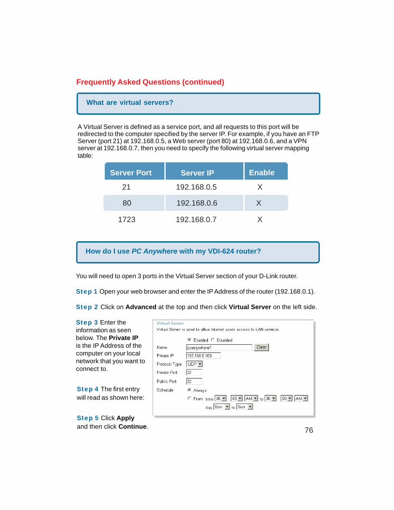
What are virtual servers?
A Virtual Server is defined as a service port, and all requests to this port will beredirected to the computer specified by the server IP. For example, if you have an FTPServer (port 21) at 192.168.0.5, a Web server (port 80) at 192.168.0.6, and a VPNserver at 192.168.0.7, then you need to specify the following virtual server mappingtable:
Server Port Server IP Enable
21 192.168.0.5 X
80 192.168.0.6 X
1723 192.168.0.7 X
How do I use PC Anywhere with my VDI-624 router?
You will need to open 3 ports in the Virtual Server section of your D-Link router.
Step 1 Open your web browser and enter the IP Address of the router (192.168.0.1).
Step 2 Click on Advanced at the top and then click Virtual Server on the left side.
Step 3 Enter theinformation as seenbelow. The Private IPis the IP Address of thecomputer on your localnetwork that you want toconnect to.
Step 4 The first entrywill read as shown here:
Step 5 Click Applyand then click Continue.
77
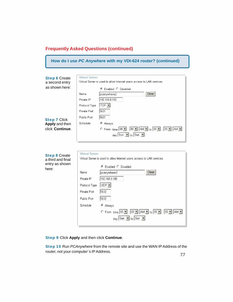
How do I use PC Anywhere with my VDI-624 router? (continued)
Frequently Asked Questions (continued)
Step 6 Createa second entryas shown here:
Step 7 ClickApply and thenclick Continue.
Step 8 Createa third and finalentry as shownhere:
Step 9 Click Apply and then click Continue.
Step 10 Run PCAnywhere from the remote site and use the WAN IP Address of therouter, not your computer´s IP Address.
78
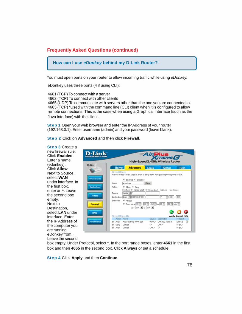
How can I use eDonkey behind my D-Link Router?
Frequently Asked Questions (continued)
You must open ports on your router to allow incoming traffic while using eDonkey.
eDonkey uses three ports (4 if using CLI):
4661 (TCP) To connect with a server4662 (TCP) To connect with other clients4665 (UDP) To communicate with servers other than the one you are connected to.4663 (TCP) *Used with the command line (CLI) client when it is configured to allowremote connections. This is the case when using a Graphical Interface (such as theJava Interface) with the client.
Step 1 Open your web browser and enter the IP Address of your router(192.168.0.1). Enter username (admin) and your password (leave blank).
Step 2 Click on Advanced and then click Firewall.
Step 3 Create anew firewall rule:Click Enabled.Enter a name(edonkey).Click Allow.Next to Source,select WANunder interface. Inthe first box,enter an *. Leavethe second boxempty.Next toDestination,select LAN underinterface. Enterthe IP Address ofthe computer youare runningeDonkey from.Leave the secondbox empty. Under Protocol, select *. In the port range boxes, enter 4661 in the firstbox and then 4665 in the second box. Click Always or set a schedule.
Step 4 Click Apply and then Continue.
79
Frequently Asked Questions (continued)
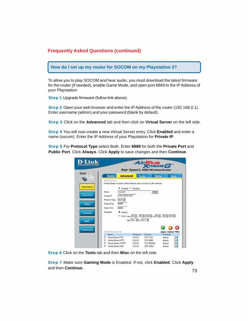
To allow you to play SOCOM and hear audio, you must download the latest firmwarefor the router (if needed), enable Game Mode, and open port 6869 to the IP Address ofyour Playstation.
Step 1 Upgrade firmware (follow link above).
Step 2 Open your web browser and enter the IP Address of the router (192.168.0.1).Enter username (admin) and your password (blank by default).
Step 3 Click on the Advanced tab and then click on Virtual Server on the left side.
Step 4 You will now create a new Virtual Server entry. Click Enabled and enter aname (socom). Enter the IP Address of your Playstation for Private IP.
Step 5 For Protocol Type select Both. Enter 6869 for both the Private Port andPublic Port. Click Always. Click Apply to save changes and then Continue.
Step 6 Click on the Tools tab and then Misc on the left side.
Step 7 Make sure Gaming Mode is Enabled. If not, click Enabled. Click Applyand then Continue.
socom
192.168.0.100
Both
6869
6869
How do I set up my router for SOCOM on my Playstation 2?
80
Frequently Asked Questions (continued)
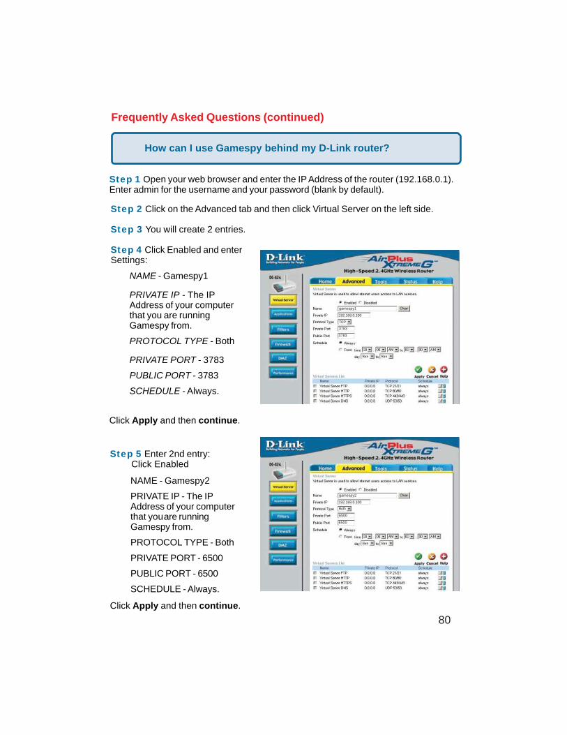
How can I use Gamespy behind my D-Link router?
Step 1 Open your web browser and enter the IP Address of the router (192.168.0.1).Enter admin for the username and your password (blank by default).
Step 2 Click on the Advanced tab and then click Virtual Server on the left side.
Step 3 You will create 2 entries.
Step 4 Click Enabled and enterSettings:
Click Apply and then continue.
Step 5 Enter 2nd entry: Click Enabled
Click Apply and then continue.
Both
192.168.0.100
gamespy1
3783
3783
192.168.0.100
gamespy2
6500
6500
Both
NAME - Gamespy1
PRIVATE IP - The IPAddress of your computerthat you are runningGamespy from.
PROTOCOL TYPE - Both
PRIVATE PORT - 3783
PUBLIC PORT - 3783
SCHEDULE - Always.
NAME - Gamespy2
PRIVATE IP - The IPAddress of your computerthat youare runningGamespy from.
PROTOCOL TYPE - Both
PRIVATE PORT - 6500
PUBLIC PORT - 6500
SCHEDULE - Always.
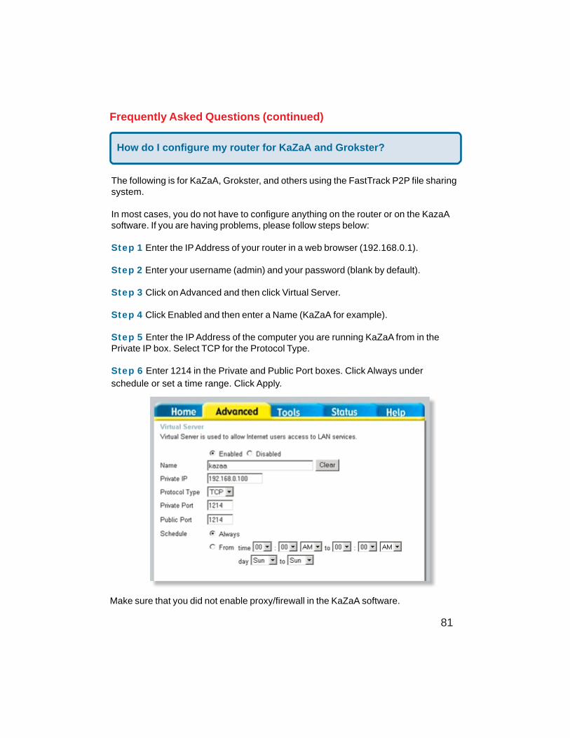
81
Frequently Asked Questions (continued)
How do I configure my router for KaZaA and Grokster?
The following is for KaZaA, Grokster, and others using the FastTrack P2P file sharingsystem.
In most cases, you do not have to configure anything on the router or on the KazaAsoftware. If you are having problems, please follow steps below:
Step 1 Enter the IP Address of your router in a web browser (192.168.0.1).
Step 2 Enter your username (admin) and your password (blank by default).
Step 3 Click on Advanced and then click Virtual Server.
Step 4 Click Enabled and then enter a Name (KaZaA for example).
Step 5 Enter the IP Address of the computer you are running KaZaA from in thePrivate IP box. Select TCP for the Protocol Type.
Step 6 Enter 1214 in the Private and Public Port boxes. Click Always underschedule or set a time range. Click Apply.
Make sure that you did not enable proxy/firewall in the KaZaA software.
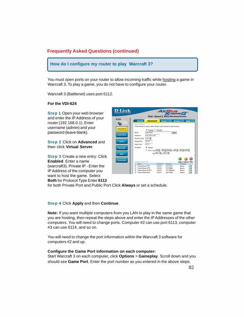
82
Frequently Asked Questions (continued)
How do I configure my router to play Warcraft 3?
You must open ports on your router to allow incoming traffic while hosting a game inWarcraft 3. To play a game, you do not have to configure your router.
Warcraft 3 (Battlenet) uses port 6112.
For the VDI-624
Step 1 Open your web browserand enter the IP Address of yourrouter (192.168.0.1). Enterusername (admin) and yourpassword (leave blank).
Step 2 Click on Advanced andthen click Virtual Server.
Step 3 Create a new entry: ClickEnabled. Enter a name(warcraft3). Private IP - Enter theIP Address of the computer youwant to host the game. SelectBoth for Protocol Type Enter 6112for both Private Port and Public Port Click Always or set a schedule.
Step 4 Click Apply and then Continue.
Note: If you want multiple computers from you LAN to play in the same game thatyou are hosting, then repeat the steps above and enter the IP Addresses of the othercomputers. You will need to change ports. Computer #2 can use port 6113, computer#3 can use 6114, and so on.
You will need to change the port information within the Warcraft 3 software forcomputers #2 and up.
Configure the Game Port information on each computer:Start Warcraft 3 on each computer, click Options > Gameplay. Scroll down and youshould see Game Port. Enter the port number as you entered in the above steps.
192.168.0.100
warcraft3
6112
6112
both
83
Frequently Asked Questions (continued)
How do I use NetMeeting with my D-Link Router?
Unlike most TCP/IP applications, NetMeeting uses DYNAMIC PORTS instead ofSTATIC PORTS. That means that each NetMeeting connection is somewhat differentthan the last. For instance, the HTTP web site application uses port 80. NetMeetingcan use any of over 60,000 different ports.
All broadband routers using (only) standard NAT and all internet sharing programs likeMicrosoft ICS that use (only) standard NAT will NOT work with NetMeeting or otherH.323 software packages.
The solution is to put the router in DMZ.
Note: A few hardware manufacturers have taken it on themselves to actually provideH.323 compatibility. This is not an easy task since the router must search eachincoming packet for signs that it might be a netmeeting packet. This is a whole lotmore work than a router normally does and may actually be a weak point in thefirewall. D-Link is not one of the manufacturers.
To read more on this visit http://www.HomenetHelp.com
How do I set up my router to use iChat? -for Macintosh users-
You must open ports on your router to allow incoming traffic while using iChat.
iChat uses the following ports: 5060 (UDP) 5190 (TCP) File Sharing 16384-16403(UDP) To video conference with other clients.
Step 1 Open your web browser and enter the IP Address of your router(192.168.0.1). Enter username (admin) and your password (leave blank).
Step 2 Click on Advanced and then click Firewall.
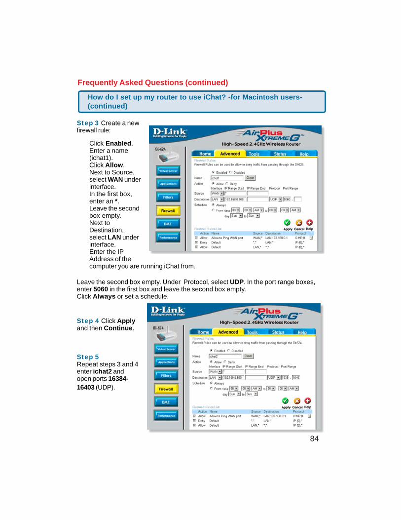
84
Frequently Asked Questions (continued)
Step 3 Create a newfirewall rule:
Leave the second box empty. Under Protocol, select UDP. In the port range boxes,enter 5060 in the first box and leave the second box empty.Click Always or set a schedule.
Step 4 Click Applyand then Continue.
Step 5Repeat steps 3 and 4enter ichat2 andopen ports 16384-16403 (UDP).
How do I set up my router to use iChat? -for Macintosh users-(continued)
Click Enabled.Enter a name(ichat1).Click Allow.Next to Source,select WAN underinterface.In the first box,enter an *.Leave the secondbox empty.Next toDestination,select LAN underinterface.Enter the IPAddress of thecomputer you are running iChat from.
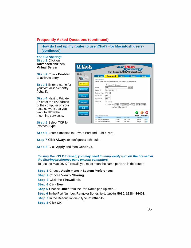
85
Frequently Asked Questions (continued)
If using Mac OS X Firewall, you may need to temporarily turn off the firewall inthe Sharing preference pane on both computers.To use the Mac OS X Firewall, you must open the same ports as in the router:
Step 1 Choose Apple menu > System Preferences.
Step 2 Choose View > Sharing.
Step 3 Click the Firewall tab.
Step 4 Click New.
Step 5 Choose Other from the Port Name pop-up menu.
Step 6 In the Port Number, Range or Series field, type in: 5060, 16384-16403.
Step 7 In the Description field type in: iChat AV.
Step 8 Click OK.
For File Sharing:Step 1 Click onAdvanced and thenVirtual Server.
Step 2 Check Enabledto activate entry.
Step 3 Enter a name foryour virtual server entry(ichat3).
Step 4 Next to PrivateIP, enter the IP Addressof the computer on yourlocal network that youwant to allow theincoming service to.
Step 5 Select TCP forProtocol Type.
Step 6 Enter 5190 next to Private Port and Public Port.
Stsp 7 Click Always or configure a schedule.
Step 8 Click Apply and then Continue.
How do I set up my router to use iChat? -for Macintosh users-(continued)
86
Frequently Asked Questions (continued)
How do I send or receive a file via iChat when the Mac OSX firewallis active? -for Macintosh users- Mac OS X 10.2 and later
“iChat cannot send or receive a file when the Mac OS X firewall is active in its defaultstate. If you have opened the AIM port, you may be able to receive a file but not sendthem.
In its default state, the Mac OS X firewall blocks file transfers using iChat or AmericaOnline AIM software. If either the sender or receiver has turned on the Mac OS X firewall,the transfer may be blocked.
The simplest workaround is to temporarily turn off the firewall in the Sharing preferencepane on both computers. This is required for the sender. However, the receiver may keepthe firewall on if the AIM port is open. To open the AIM port:
If you do not want to turn off the firewall at the sending computer, a different file sharingservice may be used instead of iChat. The types of file sharing available in Mac OS X areoutlined in technical document 106461, "Mac OS X: File Sharing" in the AppleCare Knowl-edge base online.
Note: If you use a file sharing service when the firewall is turned on, be sure to click theFirewall tab and select the service you have chosen in the "Allow" list. If you do not dothis, the firewall will also block the file sharing service. “
The following information is from the online Macintosh AppleCare knowledge base:
Step 1 Choose Apple menu > System Preferences.
Step 2 Choose View > Sharing.
Step 3 Click the Firewall tab.
Step 4 Click New.
Step 5 Choose AOL IM from the Port Name pop-up menu. The number 5190should already be filled in for you.
Step 6 Click OK.
87
What is NAT?
NAT stands for Network Address Translator. It is proposed and described in RFC-1631 and is used for solving the IP Address depletion problem. Basically, each NATbox has a table consisting of pairs of local IP Addresses and globally uniqueaddresses, by which the box can “translate” the local IP Addresses to global addressand vice versa. Simply put, it is a method of connecting multiple computers to theInternet (or any other IP network) using one IP Address.
D-Link´s broadband routers (ie: DI-604) support NAT. With proper configuration,multiple users can access the Internet using a single account via the NAT device.
For more information on RFC-1631: The IP Network Address Translator (NAT), visithttp://www.faqs.org/rfcs/rfc1631.html
Frequently Asked Questions (continued)
88
Warranty(USA only)
Subject to the terms and conditions set forth herein, GTE.Net LLC d/b/a Verizon InternetSolutions and Verizon Internet Services Inc. (collectively “Verizon Online”) provide this LimitedWarranty for the products you are obtaining through Verizon Online (“Product(s)”). ThisLimited Warranty is provided only to the person or entity (“Customer”) that originally purchasedthe Product(s) from:•Verizon Online and for• Products purchased and delivered within the fifty states of the United States and theDistrict of Columbia Limited Warranty: Verizon Online warrants that the hardware portion ofthe Product(s) will be free from material defects in workmanship and materials from thedate of original retail purchase of the Product(s) through Verizon Online for the period of oneyear (“Warranty Period”), except as otherwise stated herein. Verizon Online’s sole obligationshall be to repair or replace the defective hardware during the Warranty Period at no chargeto Customer or to refund the price at Verizon Online’s sole discretion. Such repair orreplacement will be provided by Verizon Online. The replacement hardware provided byVerizon Online may not be new or have an identical make, model or part. Verizon Online mayin its sole discretion replace the defective hardware (or any part thereof) with any reconditionedproduct that Verizon Online reasonably determines is substantially equivalent (or superior)in all material respects to defective hardware. Repaired or replacement hardware will bewarranted for the remainder of the original Warranty Period from the date of the originalpurchase from Verizon Online.If a material defect is incapable of correction or if Verizon Online determines in its solediscretion that it is not practical to repair or replace the defective hardware, the price paid byCustomer for the defective hardware will be refunded by Verizon Online upon return toVerizon Online of the defective hardware. All hardware (or part thereof) that is replaced byVerizon Online, or for which the purchase price is refunded, shall become the property ofVerizon Online upon replacement or refund. Limited Software Warranty: Verizon Onlinepasses on to Customer the warranty of the Licensor that the software portion of the Product(“Software”) will substantially conform to the Licensor’s then current functional specifications
89
for the Software, as set forth in the applicable documentation, from the date of Customer’spurchase of the Software for a period of ninety (90) days (“Software Warranty”) DIRECTLY ORINDIRECTLY, TO THE LIMITED WARRANTY. Except as otherwise required by law, includingNew York laws relating to consumer transactions, any cause of action or claim Customermay have with respect to the Product must be commenced within one (1) year after the claimor cause of action arises or such claim or cause of action is barred. Some states do not allowexclusion or limitation of incidental or consequential damages or limitations on how long animplied warrant lasts, so the foregoing limitations and exclusions may not apply. This Lim-ited Warranty provides specific legal rights and the product owner may also have other rightswhich vary from state to state.Copyright Statement: No part of this publication or document accompanying this Productmay be reproduced in any form, by any means or used to make any derivative such astranslation, transformation or adaptation without permission from Verizon Online, asstipulated by the United States Copyright Act of 1976. Contents are subject to changewithout prior notice. Copyright © 2004 by Verizon. All rights reserved. CE Mark Warning: Thisis a Class B product. In a domestic environment, this Product may cause radio interference,in which case the user may be required to take adequate measures. FCC Statement: ThisProduct has been tested and found to comply with the limits for a Class B digital device,pursuant to part 15 of the FCC Rules. These limits are designed to provide reasonableprotection against harmful interference in a residential installation. This Product generates,uses and can radiate radio frequency energy and, if not installed and used in accordancewith the instructions, may cause harmful interference to radio communication. However,there is no guarantee that interference will not occur in a particular installation. If thisProduct does cause harmful interference to radio or television reception, which can bedetermined by turning the Product off and on, the Customer is encouraged to try to correctthe interference by one or more of the following measures:• Reorient or relocate the receiving antenna.• Increase the separation between the Product and receiver.• Connect the Product into an outlet on a circuit different from that to which the receiveris connected.• Consult Verizon Online or an experienced radio/TV technician for help.• Return Product shall be packaged and shipped to Verizon Teleproducts, 400 BrandywineParkway, West Chester, PA 19380. The Customer is responsible for taking the package toa UPS Ground or a common carrier, selected by Verizon Online, with shipping chargesprepaid.
90
What Is Not Covered: This Limited Warranty provided by Verizon Online does not cover Prod-ucts, which in Verizon Online’s sole discretion, have been subjected to abuse, accident,alternation, modification, tampering, negligence, misuse, faulty installation, lack of reason-able care, repair of service in any way that is not contemplated in the documentation for theProduct or if the model or serial number has been altered, tampered with, defaced or re-moved; Initial installation, installation and removal of the Product for repair and shippingcost; Operational adjustments covered in the operating manual for the Product and normalmaintenance; Damage that occurs in shipment, due to an act of God, failures due to powersurge and cosmetic damage; Any hardware, software, firmware or other products or servicesprovided by anyone other than Verizon Online; Products that have been purchased from otherthan Verizon Online; Repair by any party other than Verizon Online or as directed by VerizonOnline will void this Limited Warranty. Limitation of Liability: TO THE MAXIMUM EXTENTPERMITTED BY LAW, VERIZON ONLINE IS NOT LIABLE UNDER ANY CONTRACT, NEGLI-GENCE, STRICT LIABILITY OR OTHER LEGAL OR EQUITABLE THEORY FOR ANY LOSS OFUSE OF THE PRODUCT, INCONVENIENCE OR DAMAGES OF ANY CHARACTER, WHETHERDIRECT, SPECIAL, INCIDENTAL OR CONSEQUENTIAL (INCLUDING, BUT NOT LIMITEDTO, DAMAGES FOR LOSS OF GOODWILL, LOSS OF REVENUE OR PROFIT, WORK STOP-PAGE, COMPUTER FAILURE OR MALFUNCTION, FAILURE OF OTHER EQUIPMENT ORCOMPUTER PROGRAMS TO WHICH THE PRODUCT IS CONNECTED WITH, LOSS OFINFORMATION OR DATA CONTAINED IN, STORED ON OR INTEGRATED WITH ANY PROD-UCT RETURNED TO VERIZON ONLINE FOR WARRANTY SERVICE) RESULTING FROMTHE USE OF THE PRODUCT RELATING TO WARRANTY SERVICE, OR ARISING OUT OFANY BREACH OF THIS LIMITED WARRANTY, EVEN IF VERIZON ONLINE HAS BEEN AD-VISED OF THE POSSIBILITY OF SUCH DAMAGES. THE SOLE REMEDY FOR A BREACH OFTHE FOREGOING LIMITED WARRANTY IS REPAIR, REPLACEMENT OR REFUND OF THEDEFECTIVE OR NON-CONFORMING PRODUCT. THE MAXIMUM LIABILITY OF VERIZONONLINE UNDER THIS WARRANTY IS LIMITED TO THE PURCHASE PRICE OF THE PROD-UCT COVERED BY THE WARRANTY.THE FOREGOING EXPRESS WRITTEN WARRANTIES AND REMEDIES ARE EXCLUSIVEAND ARE IN LIEU OF ANY OTHER WARRANTIES OR REMEDIES, EXPRESS, IMPLIED ORSTATUTORY.Governing Law: This Limited Warranty shall be governed by the laws of the State of NewYork, without reference to its principles or conflicts of laws. CUSTOMER AND VERIZONONLINE CONSENT TO THE EXCLUSIVE PERSONAL JURISDICTION OF AND VENUE IN ACOURT LOCATED IN NEW YORK COUNTY, NEW YORK, FOR ANY SUITS OR CAUSES OFACTION CONNECTED IN ANY WAY, Period”), provided that the Software is properly installedon approved hardware and operated as contemplated in its documentation. Verizon Onlinefurther passes on to Customer the warranty of the Licensor that, during the Software WarrantyPeriod, the magnetic media on which the Licensor delivers the Software will be free ofphysical defects
91
(10/11/04)
The Licensor’s sole obligation shall be to replace the non-conforming Software (or defectivemedia) with software that substantially conforms to the Licensor’s functional specificationsfor the Software or to refund the purchase price for the Software at Verizon Online’s solediscretion. The replacement Software is provided only to the original Customer and is sub-ject to the terms and conditions of the license granted by the Licensor for the Software.Software will be warranted for the Software Warranty Period set forth above from the date thereplacement Software is returned to Customer. If a material non-conformance is incapableof correction, or if Verizon Online determines in its sole discretion that it is not practical toreplace the non-conforming Software, the price paid by the Customer for the non-conformingSoftware will be refunded by Verizon Online; provided that the non-conforming Software (andall copies thereof) is returned to Verizon Online. The license granted respecting any Softwarefor which a refund is given automatically terminates. Non-Applicability of Warranty: TheLimited Warranty provided hereunder for hardware and software Product will not be appliedto and does not cover any Product not purchased directly through and from Verizon Online.Submitting a Claim: Customer may return the Product to Verizon Online based on its returnpolicy. In case the return policy period has expired and Product is within the Warranty Period,Customer shall submit a claim to Verizon Online as outlined below, provided that only Cus-tomer may submit a claim:• Customer must submit with the Product as part of the claim a written description of thehardware defect or Software non-conformance in sufficient detail to allow Verizon Online toconfirm the same.• Customer must obtain a Return Authorization (“RA”) number from Verizon Online and, ifrequested, provide written proof of purchase of Product (such as a copy of the dated purchaseinvoice of the Product) before the warranty service is provided.• Upon Customer’s request, Verizon Online will provide Customer with an RA and postage-paid package for the original Product under warranty. No Cash on Delivery (“COD”) returnsare allowed.• After an RA number is issued, the defective Product must be packaged securely in theprovided packing material, original or other suitable shipping package, to ensure that it willnot be damaged in transit, and the RA number must be prominently marked on the outsideof the package. All accessories and manuals must be included in the shipping package,such as the power cord and Ethernet cable.
VDI-624
3/17/05