
D E DAFFODIL INTERNATIONAL UNIVERSITY
73
1 STUDY ON AN IDEAL GAS REGULATING AND METERING STATION FOR GAS SUPPLY TO A 50 MW POWER PLANT (NAVANA CNG LTD.) A Project and Thesis submitted in partial fulfillment of the requirements for the Award of Degree of Bachelor of Science in Electrical and Electronic Engineering Submitted by Md. Ashraful Alam ID: 152-33-2618 Supervised by Professor Dr. M. Shamsul Alam Dean Faculty of Engineering Daffodil International University Dhaka, Bangladesh DEPARTMENT OF ELECTRICAL AND ELECTRONIC ENGINEERING FACULTY OF ENGINEERING DAFFODIL INTERNATIONAL UNIVERSITY November 2018
Transcript of D E DAFFODIL INTERNATIONAL UNIVERSITY
1
STUDY ON AN IDEAL GAS REGULATING AND METERING
STATION FOR GAS SUPPLY TO A 50 MW POWER PLANT
(NAVANA CNG LTD.)
A Project and Thesis submitted in partial fulfillment of the requirements for
the Award of Degree of Bachelor of Science in Electrical and Electronic
Engineering
Submitted by Md. Ashraful Alam
ID: 152-33-2618
Supervised by
Professor Dr. M. Shamsul Alam Dean
Faculty of Engineering
Daffodil International University Dhaka, Bangladesh
DEPARTMENT OF ELECTRICAL AND ELECTRONIC ENGINEERING FACULTY OF ENGINEERING
DAFFODIL INTERNATIONAL UNIVERSITY November 2018

2
Certification
This is to certify that this project and thesis entitled “DESIGN OF AN IDEAL GAS
REGULATING AND METERING STATION FOR GAS SUPPLY TO A 50 MW POWER
PLANT (NAVANA CNG LTD.)” is done by the following students under my direct supervision and
this work has been carried out by them in the laboratories of the Department of Electrical and Electronic
Engineering under the Faculty of Engineering of Daffodil International University in partial fulfillment of
the requirements for the degree of Bachelor of Science in Electrical and Electronic Engineering. The
presentation of the work was held on November 2018. Signature of the candidates
_____________________ Name: Md. Ashraful Alam ID #: 152-33-2618
Countersigned
_______________________ Professor Dr. M. Shamsul Alam Dean Designation Department of Electrical and Electronic Engineering Faculty of Science and Engineering Daffodil International University.

3
The project and thesis entitled “STUDY ON AN IDEAL GAS REGULATING AND
METERING STATION FOR GAS SUPPLY TO A 50 MW POWER PLANT (NAVANA
CNG LTD.,” submitted by Name: Md. Ashraful Alam, ID: 152-33-2618, Session: Fall 2015
has been accepted as satisfactory in partial fulfillment of the requirements for the degree of
Bachelor of Science in Electrical and Electronic Engineering on 01 August 2018.
BOARD OF EXAMINERS ____________________________ Dr. Engr. … Chairman Professor Department of EEE, DIU ____________________________ Dr. Engr. --- Internal Member Professor Department of EEE, DIU ____________________________ Dr. Engr. --- Internal Member Professor Department of EEE, DIU

4
ACKNOWLEDGEMENT First of all I would like to thank Engineer Atiur Rahman, General Manager (Training &
Development) Navana CNG Ltd., for allowing me to do internship and work with them.
We acknowledge my gratitude to our study supervisor, Professor Dr. M. Shamsul Alam, Dean,
Faculty of Engineering for his valuable suggestions and guidance throughout this study report
work.
We are thankful to honorable Professor Dr. Yousuf Mahbubul Islam, Vice Chancellor, Daffodil
International University for providing golden opportunity for achieving our degree of B.Sc. in
Electrical and Electronic Engineering and his best co-operation.
We are grateful to Professor Dr. M. Shamsul Alam, Dean, and Faculty of Engineering and Head
of the Department of Electrical and Electronic Engineering, Daffodil International University for
his valuable suggestions.
We are also obliged to Md. Imrul Kaish, Lecturer of the Department of Electrical and Electronic
Engineering, Daffodil International University for his Cooperation.
Finally, I would like to thank all my teachers, students and staff of Department of Electrical and
Electronic Engineering at Daffodil International University and all of my family members and
friends whose names are not mentioned here.
Thanks to all
Authors

5
ABSTRACT
In gas transmission and distribution system, the gas pressure and flow rate are controlled by
using CGS, TBS, DRS and RMS. It is important to supply uninterrupted gas at a desired
pressure and flow rate to the customer premises. The Regulating and Metering Station
(RMS) is generally used for controlling the gas pressure and measuring the gas volume for
fiscal purpose. It is apparent that proper design of RMS is very important for a customer for
supplying desired amount of gas at a required pressure as well as measuring the supplied gas
accurately which is very much crucial for gas supplier in fiscal context. A large number of
RMS’s are used for gas supply to different customers in the Titas franchise area. The major
objective of this project is to design an ideal gas Regulating and Metering Station for
uninterrupted gas supply to a 50 MW power plant. In this project work, fluid characteristics,
process data, gas safety rules, International codes and standards (ASTM, ASME ANSI, API)
have been followed for the proposed RMS design. Design considerations, selection criteria
and installation of RMS equipments are incorporated. Safety and Environmental issues have
been considered in designing the gas facilities for the power plant. The negative effects on
environment are negligible. The gas load of the power plant is calculated around 12
MMSCFD at minimum outlet pressure of 50 psig. Design has been checked allowing
variation of some related variables such as inlet pressure, specific density, specific heat,
compressibility factor and heating value. Variation of these parameters needs no change in
the design. Instrumentation and piping diagrams of the proposed RMS are also shown in the
report. Some recommendations have been made for improvement of the RMS design.
Finally, cost estimation is performed for the project. The cost estimation of the project have
been calculated on the basis of preconstruction expenditure, construction cost and material
cost. The total cost of the project is estimated as Tk. 494.463 Lakh.
6
TABLE OF CONTENT
Title Page CHAPTER 1: INTRODUCTION 01 1.1 Objectives 02 1.2 Methodology 02 CHAPTER 2: LITERATURE REVIEW 03 2.1 Typical Gas Regulating and Metering System 03 2.1.1 Conditioning 03 2.1.2 Regulating 03 2.2 Equipment of a Regulating and Metering Station 04 2.2.1 Inlet and outlet connections 05 2.2.2 Insulating joint 05 2.2.3 Emergency shut down (ESD) valve 05 2.2.4 Headers 05 2.2.5 Knock out drum (KOD)/ scrubbers and filter separators 05 2.2.6 Regulator Pilots 06 2.2.7 Set point 06 2.2.8 Spring Action 07 2.2.8.1 Overpressure protection 07 2.2.8.1.1 Pressure relief valves 07 2.2.8.1.2 Automatic Shutoffs/Slam-Shuts valves 07 2.2.8.1.3 Backpressure regulators 07 2.2.8.2 Pressure switching valves 08 2.2.9 Valve 08 2.2.9.1 Types of valve 09 2.2.10 Gas Heating System 10 2.2.10.1 Water bath heater 10 2.2.10.2 Heat Exchangers 10 2.2.10.3 Electrical Heater 11 2.2.11 Gas Metering System 11 2.2.11.1 Positive displacement Meter 12 2.2.11.1.1 Diaphragm Meter 12 2.2.11.1.2 Rotary Meter 13 2.2.11.1.3 Turbine Meters 13 2.2.11.1.4 Ultrasonic Meters 16 2.2.12 Auxiliary devices Used with Meters: 17
7
2.2.12.1 Electronic Volume Correctors 17 2.2.12.2 Flow Computers : 17 2.2.12.3 Chart Recorder 18 2.2.12.4 Pressure Gauge 19 2.2.12.5 Temperature measurement 20 2.2.12.6 Density measurement 21 2.2.13 Supervisory Control and Data Acquisition (SCADA) System 21 CHAPTER 3 : RMS DESIGN CONSIDERATIONS 22 3.1 Design Parameters 23 3.2 Regulating and Metering Station Configuration 24 3.2.1 Recommended Minimum Requirements 25 3.3 Station specifications 26 3.3.1 Volume 26 3.3.2 Pressure conditions 26 3.3.2.1 Inlet pressure 26 3.3.2.2 Outlet pressure 27 3.3.3 Type of load 27 3.3.4 Gas conditions 27 3.3.5 Ambient conditions 27 3.3.6 Site condition 28 3.4 Pipe sizing 28 3.4.1 Velocity formula 28 3.4.2 Panhandle formula 28 3.4.3 Wall thickness of pipe 29 3.4.3.1 Yield strength 29 3.4.3.2 Minimum yield strength (Y) 30 3.5 Headers 31 3.6 Filtering system 31 3.6.1 Liquid separation system 32 3.6.1.1 Criteria of a well designed separator 32 3.6.2 Filter separator design criteria 33 3.6.2.1 Gas capacity design of separator 33 3.6.2.2 Liquid capacity design of separator 34 3.6.3 Vessel design consideration 35 3.7 Regulators 36 3.7.1 Regulators installed 37 3.7.1.1 Parallel installation of regulators 37 3.7.1.2 Pressure sensing point 38
8
3.7.2 Inlet and outlet connections 39 3.7.2.1 Regulator sizing 39 3.7.2.2 Pressure setting 43 3.8 Heating capacity of gas heater 43 3.9 Meter selection 44 3.10 Optional short-coupled installation 44 3.12 Strainers or Filters 46 3.13. Over-range protection 46 3.14 By- pass 47 3.14.1 Additional installation requirements 47 3.15 Accessory installation 47 3.15.1 Temperature measurement 48 3.15.2 Pressure measurement 48 3.15.3 Density measurement 48 3.16 Flow conditions: 48 CHAPTER 4: GAS LOAD CALCULATION 49 4.1 Gas source 49 4.2 Gas based Power Plant 49 4.2.1 Gas load for 50 MW power plant 50 CHAPTER 5 : SAFETY AND ENVIRONMENTAL ASPECT OF RMS 52 5.1 Environmental impacts of proposed gas facilities for the power plant 52 5.2 Environmental Consideration 53 5.3 Safety Consideration 53 5.3.1 Gas quality 53 5.3.2 Wall thickness of pipe 53 5.3.3 Pressure rating of materials 53 5.3.4 Control of overpressure in the system 53 5.3.5 Installation of valves 54 5.3.6 Location of meters and regulators 54 5.3.7 Safety distance of pipeline 54 5.3.8 Controlling Hazards 55 5.3.9 Prevention of eddy current 55 5.3.10 Leak detector 55 5.3.11 Fire Extinguisher 55 5.3.12 Protection against corrosion 55 5.3.13 The lighting arrangement 56

9
5.3.14 Major activities of a Project 56 CHAPTER 6 : CONCLUSIONS AND RECOMMENDATIONS 57 6.1. Conclusions 57 6.2 Recommendations 58 References 59
10
LIST OF FIGURES
Figure 1.1: Pipeline Network 02
Figure 2.5: Pilot-operated regulator 06
Figure 2.2.9: Safety valve with compressore machine 09
Figure 2.2.11: Pressure Gas with Metering System 12
Figure 3.7: Regulators with comperssore machine 37
Figure. 3.7.2.1 : Regulator selection chart 41
Figure 3.10: Short coupled installation of an in-line gas turbine meter
(Minimum Length)
45
Figure 3.11. Straightening Vanes 45
Figure 4.1. Schematic diagram of 4" DN ×500 psig pipe line 49
11
LIST OF TABLES
Table 3.4.3.2 Strength of Line pipe Steel 30
Table 3.6.2.1: Values of separator coefficient, Kl (Kumar,1987) 33
Table 3.7.2.1: Cg value of regulator 40
Table 3.7.2.2: Maximum flow rates of regulator 41
Table 3.7.2.3: Maximum flow rates of regulator(cont’d) 42
Table 5.3.7 Safety distance of pipeline 54
Figure 3.11. Straightening Vanes 45
Figure 4.1. Schematic diagram of 4" DN ×500 psig pipe line 49
12
CHAPTER 1
INTRODUCTION
A network of transmission pipeline system transports natural gas from producing fields to
consumers. Gas transmission pipeline normally operates at high pressure of 1000/960/850/350
psig.The customers usually do not use gas at such high pressures. It is necessary to control the
pressure and flow rate for supplying gas to a customer at desired pressure and flow rate. In gas
transmission and distribution network, the gas pressure and flow rate are controlled at
pressure reduction stations located at suitable places. There are known as City Gate Station
(CGS), Town Bordering Station (TBS), District Regulating Station (DRS), Regulating and
Metering Station (RMS). After reducing pressure through these stations, gas is supplied to
different bulk customers like Power and Fertilizer Producer of Government Sector,
Independent power producers (IPP), Small Power Plant (SPP), Captive Power Plants (CPP)
and Non bulk customers such as industrial, commercial and domestic customers.
Regulating and Metering Station means a station comprising of Regulator, Meter and other
equipments necessary for the delivery of specification gas to a customer. Pressure Regulator
means all devices required to maintain a specified pressure at the outlet of the RMS under
variable gas flow conditions. Meter means all devices to be installed, operated and maintained
by the company for measuring, recording and computing the gas flow volumes delivered to
the customer.
This study aims to undertake and estimate of design an ideal Regulating and Metering Station
for gas supply to a 50 MW power plant in accordance with International codes and standards
(ASTM, ASME ANSI, API). The design will be carried out according to the fluid
characteristic and process data. Technical details of different equipments of the RMS will be
studied. The findings can then be incorporated in designing an improved RMS. Cost
estimation will be conducted for the proposed RMS design and construction for gas supply to
the said power plant.

13
A schematic diagram of pipeline network is shown in the following:
Gas Gathering Line Transmission
Gas Field Process TBS/
Plant CGS/DRS
Pipeline
1000 Psig
150/50 Psig
Power Plant/Industry RMS/ CMS
Figure 1.1: Pipeline Network
1.1 Objectives
The main objectives of this study are as follows
Design of an ideal gas Regulating and Metering Station to supply conditioned gas
at a desired pressure as per requirement of the power plant.
Cost estimation of the proposed RMS.
1.2 Methodology
Literature review of different equipments of the Regulating and Metering Station.
Surveying of the proposed power plant RMS area including gas source such as
CGS/TBS/DRS or any high pressure gas line.
Gas load calculation as per catalogue of gas based power station.
Consult International Standards and Codes (ASTM, ASME ANSI, API) and
there practiced by Titas Gas Transmission and Distribution Company Ltd.
Design of the proposed ideal RMS considering all criteria.
Cost estimation of the proposed RMS based on preconstruction
expenditure, construction cost and material cost etc.
14
CHAPTER 2
LITERATURE REVIEW
Regulating and Metering Station (RMS) means a station comprising of Regulator, Meter and
other equipments necessary for the delivery of specification gas to the customer. Pressure
Regulator means all devices required to maintain a specified pressure at the outlet of the RMS
under variable gas flow conditions. Meter means all devices to be installed, operated and
maintained by the company for measuring, recording and computing for fiscal purpose the gas
flow volumes delivered to the customer.
In this chapter, typical gas regulating and metering system, different types of RMS equipments
and their working principle, advantages and disadvantages will be discussed.
2.1 Typical Gas Regulating and Metering System
Typical gas regulating and metering systems are gas conditioning, regulating and metering
which described below.
2.1.1 Conditioning
Natural gas quality has a strong effect on operation of the regulating and metering station and
measurement system. The gas should be pipeline quality gas. Gas conditioning is the technique to
remove surge of liquid, condensate, water and entrained solids from gas stream by using separator
and rising up the temperature of gas at a desired level to prevent hydrate formation by using heater
to prevent the damage of regulator and meter 2.1.2 Regulating
Regulating is the technique to control the flow of gas and maintain the system pressure and
flow with certain acceptable limit of a regulating station.
2.1.3 Metering
Gas metering is the technique to measure the gas volumes for transmission system, CGS, TBS,
DRS and RMS. The metering bank consists of meter runs according to AGA report for the
computation of the gas volume. Different types of meters are used for gas metering.
15
2.2 Equipment of a Regulating and Metering Station
The Regulating and Metering Station (RMS) consists of inlet pipeline with filter separator
pressure regulator, relief valve and meter. Details of the station are given below:
(i) Insulating joint
(ii) Inlet emergency shut down (ESD) valve
(iii) Knock out drum (KOD)/ scrubbers and filter separators.
(iv) Gas heaters or heat exchanger
(v) Valves and valves actuators
(vi) Slam shut valve
(vii) Relief valves
(viii) Pressure regulators
(ix) Silencers
(x) Meters
(xi) Liquid separator.
(xii) Pressure Gauge (xiii) Temperature Gauge
(xiv) Chart recorder
(xv) Differential pressure transmitter
(xvi) Temperature transmitter
(xvii) Density and specific gravity transducer
(xviii) Gas Chromatograph
(xix) Flow Computer
(xx) Electronic Volume Corrector (EVC)
(xxi) Supervisory Control and Data Acquisition (SCADA) System
(xxii) Condensate tank
(xxiii) Weld-neck Flanges, Blind Flanges, Metallic and Asbestos Gaskets, Tees,
Elbows, End caps, Reducers, Saddle/weld-o-lets, Needle valves, Screwed gate
and ball valves, Socket welded fittings (Flange, Tee, Elbow, Reducer etc.),
Screwed Fittings, SS tubes, Compression Coupling and Stud Blots (As per
requirements), etc.
16
2.2.1 Inlet and outlet connections
The piping to and from regulator should be supported adequately to minimize pipe strains. The
piping should be designed to have adequate capacity for the expected maximum flow and the
pressure conditions. Velocities in regulator valve passages can reach sonic velocity conditions.
High velocities create noise so piping should be sized to keep gas velocities at a reasonable level.
There are specific pipeline velocity limits used by many companies to maintain a relatively quiet
pipeline system and to keep pressure losses low. Such limiting velocities range between 50 feet
per second to a maximum of approximately 400 feet per second. There are situations where higher
velocities may be required for short distances; however, the designer should calculate the pipe
velocities to be encountered and determine the steps that may be necessary to maintain
satisfactory noise levels.
2.2.2 Insulating joint
To protect eddy current producing from transmission and distribution network which damage the
pipeline of RMS, insulating joints are used at station inlet and outlet of RMS.
2.2.3 Emergency shut down (ESD) valve
To isolate the RMS from transmission network in case of emergency, ESD valve is placed at
inlet of the station.
2.2.4 Headers
A header is a way to combine multi sources or multi-outlets into a single source or outlet. Headers
need to be designed to distribute the gas symmetrically. They are typically larger sized pipe, tees,
and caps. Headers are used when more than one regulator or meter run are required. In sizing
headers it is a rule of thumb that the cross sectional area of the header be 1.5 times larger than the
sum of the inlet or outlet cross sectional area (which ever is larger).
2.2.5 Knock out drum (KOD)/ scrubbers and filter separators
Knock out drum (KOD) is one kind of liquid separator and two stage filter separator. Liquid,
Condensate are separated through the KOD.
17
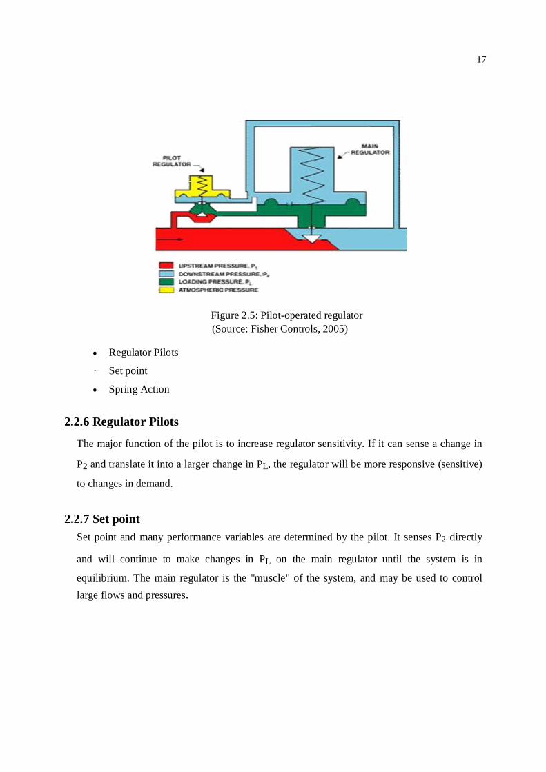
Figure 2.5: Pilot-operated regulator (Source: Fisher Controls, 2005)
Regulator Pilots
· Set point
Spring Action
2.2.6 Regulator Pilots
The major function of the pilot is to increase regulator sensitivity. If it can sense a change in
P2 and translate it into a larger change in PL, the regulator will be more responsive (sensitive)
to changes in demand.
2.2.7 Set point
Set point and many performance variables are determined by the pilot. It senses P2 directly
and will continue to make changes in PL on the main regulator until the system is in
equilibrium. The main regulator is the "muscle" of the system, and may be used to control large flows and pressures.
18
2.2.8 Spring Action
Notice that the pilot uses a spring-open action as found in direct-operated regulators. The
main regulator, shown in Figure 1, uses a spring-close action. The spring, rather than loading
pressure, is used to achieve shutoff. Increasing PL from the pilot onto the main diaphragm
opens the main regulator.
2.2.8.1 Overpressure protection
To prevent personal injury, equipment damage or leakage due to escaping gas or bursting of
pressure-containing parts, it is necessary to install adequate overpressure protection when
installing a pressure reducing regulator. Adequate overpressure protection should also be installed
to protect all downstream equipment in the event of regulator failure. Some regulators are made
with internal overpressure relief, whereas others require the installation of a separate relief valve
or an additional regulator to act as a monitor. There are also shut-off devices that are designed
specially to handle overpressure.
2.2.8.1.1 Pressure relief valves
A pressure relief valve limits pressure buildup (i.e, prevents overpressure) at its location in a
pressure system. The relief valve opens to prevent a rise of inlet pressure in excess of a
specified value. The pressure at which the relief valve begins to open pressure is the relief
pressure setting. Pressure relief valves can be direct-operated or pilot- operated.
Relief valve and backpressure regulators are the same devices. The name is determined by the
application.
2.2.8.1.2 Automatic Shutoffs/Slam-Shuts valves
A pressure shutoff or slam-Shut device Shuts off the flow whenever the sensed control
pressure violates a set limit. Depending on the capacity of the device selected, it may be able
to shut off in response to a low-pressure condition only a high- pressure condition only or
both.
2.2.8.1.3 Backpressure regulators
A backpressure regulator maintains a desired upstream pressure by varying the flow in
response to change in upstream pressure.
19
2.2.8.2 Pressure switching valves
Pressure switching valves are used in pneumatic logic systems. These valves are for either two-
way or three-way switching. Two way switching valves are used for on/off service in pneumatic
systems. Three-way switching valves direct inlet pressure from one outlet port to another
whenever the sensed pressure exceeds or drops below a preset limit.
2.2.9 Valve
A valve is a device that regulates the flow of a fluid (gases, liquids, fluidized solids, or
slurries) by opening, closing, or partially obstructing various passageways. Valves are
technically pipe fittings, but are usually discussed as a separate category. In an open valve,
fluid flows in a direction from higher pressure to lower pressure.
Valves are used in oil and gas, power generation, mining, water reticulation, sewerage and
chemical manufacturing.
Valves may be operated manually, either by a hand wheel, lever or pedal. Valves may also be
automatic, driven by changes in pressure, temperature, or flow. These changes may act upon a
diaphragm or a piston which in turn activates the valve, examples of this type of valve found
commonly are safety valves fitted to hot water systems or boilers.

20
Figure 2.2.9: Safety valve with compressore machine
2.2.9.1 Types of valve
There are different types of valves are used such as Gate valves, Globe valves, Ball valves,
Plug valves, Diaphragm valves, Butterfly valves and Check valves.
Gate valves are generally used in systems where low flow resistance for a fully open valve is
desired and there is no need to throttle the flow. Globe valves are used in systems where good
throttling characteristics and low seat leakage are desired and a relatively high head loss in an
open valve is acceptable. Ball valves allow quick, quarter turn on-off operation and have poor
throttling characteristics. Plug valves are often used to direct flow
21
between several different ports through use of a single valve. Diaphragm valves and pinch
valves are used in systems where it is desirable for the entire operating mechanism to be
completely isolated from the fluid. Butterfly valves provide significant advantages over other
valve designs in weight, space, and cost for large valve applications. Check valves
automatically open to allow flow in one direction and seat to prevent flow in the reverse
direction. A stop check valve is a combination of a lift check valve and a globe valve and
incorporates the characteristics of both. Safety/relief valves are used to provide automatic
over pressurization protection for a system.
2.2.10 Gas Heating System
The heating system is provided to prevent the possibility of gas freezing and hydrates
formation, due to the pressure drop during the reducing step in regulating system and
pipelines, caused by the Joule-Thomson effect. A convenient rule of thumb indicates that a 15
psig reduction in pressure of natural gas is associated with a 1°F decrease in temperature
(Roy,1989). Preheating of the gas is necessary for smooth operation of the gas station and
correct flow measurement. Pre heaters are installed to heat the gas after the gas has passed the
filter and before pressure reduction.
There are several types of heaters which may be used in regulating and metering station.
Water bath heater, Heat exchangers and electric heater may be used depending on the station
capacity and design. 2.2.10.1 Water bath heater
Water bath heater is one kind of indirect fired heater. Water bath heaters are often used in
regulating and metering stations. The purpose is to heat the gas so that after a pressure drop is
taken across a pressure regulator, the gas will be above the hydrate point. It consists of tubular
elements, carrying the gas immersed in a water bath, which is maintained at the required constant
temperature by the use of a burner fitted with standard controls and safety devices to maintain the
desired exit temperature in the gas stream. The capacity range of water bath heater within 15 kw
to 1170 kw according to heat required for heating gas.
2.2.10.2 Heat Exchangers
Heat exchangers are used to increase the temperature (above the dew point) of natural gas.
Their performance is based on the heat exchanger between water (or steam) and the gas to be

22
treated. Heat exchangers are designed to be suitable for an easy inspection and cleaning of all
the parts.
2.2.10.3 Electrical Heater
This may take the from of a pressure vessel located in the gas stream in which are inserted
electric immersion heaters. Such an arrangement would normally be confined to relatively
small gas flow. A form of heating suitable for low input needs, such as impulse piping is that
of heating tapes wrapped around the section of piping and thermally insulated on the outside.
2.2.11 Gas Metering System
Gas metering is very important for transmission and distribution system and metering station.
Throughout the world, gas measurement utilizes two basic principles to measure gas volumes,
positive displacement meter and inferential meters. Positive displacement meters comprise the
large majority of measurement devices in use while inferential meters are used primarily for
large volume measurement and thus fewer applications.
In RMS the metering bank consists of one metes runs design accordance to AGA report no.3
for the computation, of the gas volume flow delivered. Different types of meters are used for
gas metering which describes as follows :
Positive displacement - Diaphragm meter ,Rotary meter & Turbine meter
Differential pressure measurement – Orifice, Venturi and nozzle meter
Ultrasonic flow meter - Doppler flow meter
Fluid oscillatory – Vortex meter, Swirl meter
Electro magnetic flow meter – Magnetic flow meter
Direct mass – Coriolis mass flow meter.
Thermal - Thermal profile flow meter.
23
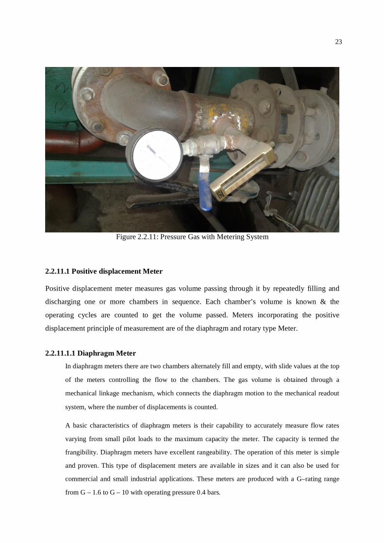
Figure 2.2.11: Pressure Gas with Metering System
2.2.11.1 Positive displacement Meter Positive displacement meter measures gas volume passing through it by repeatedly filling and
discharging one or more chambers in sequence. Each chamber’s volume is known & the
operating cycles are counted to get the volume passed. Meters incorporating the positive
displacement principle of measurement are of the diaphragm and rotary type Meter.
2.2.11.1.1 Diaphragm Meter
In diaphragm meters there are two chambers alternately fill and empty, with slide values at the top
of the meters controlling the flow to the chambers. The gas volume is obtained through a
mechanical linkage mechanism, which connects the diaphragm motion to the mechanical readout
system, where the number of displacements is counted.
A basic characteristics of diaphragm meters is their capability to accurately measure flow rates
varying from small pilot loads to the maximum capacity the meter. The capacity is termed the
frangibility. Diaphragm meters have excellent rangeability. The operation of this meter is simple
and proven. This type of displacement meters are available in sizes and it can also be used for
commercial and small industrial applications. These meters are produced with a G–rating range
from G – 1.6 to G – 10 with operating pressure 0.4 bars.
24
2.2.11.1.2 Rotary Meter
This type of meter contains two oppositely rotating impellers, which are the measuring
mechanism. The volume of gas is directly related to the number of revolutions of one of the
impeller shafts. The rotary meter’s capacity rating is much greater than the diaphragm meter.
Rotary meters are available in ranges of 800 to 102,000 CFH. It can be used in high pressure
applications with up to an ANSI 600 rating available. These meters are compact and reliable,
however since the operation depends on maintaining proper clearance between the impellers
and the case, they can be susceptible to stress and if a malfunction occurs, then the gas flow
could be stopped. The rotary meter is limited at high pressure. Therefore this meter although
an excellent performance is not regarded as appropriate for large capacity, high pressure
metering of natural gas.
2.2.11.1.3 Turbine Meters
The turbine meter is classified as a rotary inferential meter. These flow meters are used
successfully in both liquid and gas measurement. Turbine meters are velocity sensing
meters with the volume of fluid being derived from the rotations of the turbine rotor. The
speed of this rotor is proportional to flow rate. Turbine meters has been established as a
means of measuring fluid for nearly 80 years. Since the 1950s, they have been considered
favorably for the measurement of large volume gas flows. The designs have proved
receivable, accurate and repeatable. As well as being used as the primary measurement
standard, axial flow gas turbine meters are increasingly being used as calibration and
reference meters.
The turbine meter (Figure-2.6) has wide range ability (to 200:1 depending on meter size
and line pressure), greater accuracy potential and more versatility in adding mechanical
and electronic auxiliary devices. Like an orifice meter, a turbine meter does not impede
flow if there is damage or failure. This is important when maintaining gas service to a
downstream consumer is critical.
Two basic assumptions relate to the operation of the turbine meter:
1) The angular velocity of the rotor is proportional to the volumetric flow rate passing
through the meter.
25
2) The pulsed output frequency of the pick-up is proportional to angular velocity of
the rotor.
The axial flow gas turbine meter comprised of three main components: i. The body through which the gas passes. ii. A rotor with bearings and supporting structure. iii. A device to transfer the internal revolutions of the rotor to an external counter.
Gas flowing through the meter impinges on turbine blades located centrally along the axis of
the unit. Turbine blades are free to rotate, and do so in a manner directly proportional to the
velocity of the gas passing the blades.
The area of the rotor face as defined by the mean radius of the rotor can be determined.
Permanent magnets installed in the hub of the rotor, turn with the rotor to produce a magnetic
field, which passes through a coil. As each of the magnets pass the coil a separate and distinct
voltage pulse is created. The frequency of these pulses is proportional to the velocity of the
rotor is also proportional to the flow rate. Each pulse is also proportional to a small unit of
volume. The pulses, the effective flow rate and total flow are transmitted by frequency and by
counting the pulses. The output frequency has been conditioned into a square wave through a
preamplifier. This conditioning allows it to be transferred to a remote flow computer. Each
pulse represents only a small incremental volume of flow. Since the turbine meter measures
volume at line conditions, the gas laws can be applied to change the register volume to base
conditions.
3) Inferential Meters Orifice and turbine meters operate on the inferential measurement principle. Here the flow
rate is found by inferring from other measured variables.
i) Orifice Meters
Orifice Metering is the most common form of gas metering used throughout the world for the
accounting of large volumes of natural gas. It is also used for the measurement of liquids.

26
Based on the differential pressure method, the rate of flow is computed on the basis of long
established physical principles. The common equation used for determining the total flow
volume being based on the current AGA or ISO Standard.
The orifice plate meter is classified as a differential pressure (dp) meter. There are a number
of types of flow meters, with different shapes and sizes, which fit into this category of
inferring flow rate from the pressure drop across a restriction. An Orifice plate flow meter
system consists of three discrete components the meter tube, the orifice assembly, and the
differential pressure gauge. The meter tube and orifice assembly are considered to be the
primary element and the differential pressure gauge, pressure and temperature gauge or
recorder are being referred to as secondary element.
Orifice meters must be designed, fabricated and installed according to AGA Report no 3
(ANSI/API 2530). When designing an orifice meter run, differential pressure should range
between 10” and 90” of water column for a 100” chart and 20” and 180” of water column for
a 200” chart. This avoids large measurement errors at low differential pressures and
overhanging the chart. Although AGA Report no 3 does not specify upper or lower
differential pressure limits, industry standard is 10” to 200” of water column. If the
differential pressure falls below 10” of water column, it does not stabilize and measurement
errors result.

27
The orifice plate meter is classified as a differential pressure (dp) meter. There are a number of
types of flow meters, with different shapes and sizes, which fit into this category of inferring flow
rate from the pressure drop across a restriction. An orifice plate flow meter system consists of two
basic elements, namely the primary flow element, which is the orifice plate, and secondary
elements which include the differential pressure transmitter, or differential pressure indicating
device such as a manometer, and the associated pipe work and valves. The orifice plate meter
relies on the principle of when a fluid is flowing a closed medium (a pipe) and encounters a
restriction, a pressure drop is developed. This pressure drop is related to the flow rate of the fluid.
By measuring the differential pressure across the orifice plate (upstream and downstream of the
plate) and the condition at which the orifice is being used, then this pressure differential can be
translated into a volume flow rate according to a formula. Accurate measurement is definitely
possible with this type of flow meter, if malfunctions occur the flow of gas will not be stopped.
Orifice meters are not limited by high pressure or high flow so they can therefore be considered
for high flow, high pressure gas metering. Naturally the correct selection of orifice plate type is
important.
The rangeability of a single orifice meter is about 3:1, by adding further orifice meter runs in parallel,
this rangeability increases by the square. That is, a dual run meter station would have a theoretical
rangeabilitiy of approximately 9:1. Rangeability is the term used with meters to express the flow range
over which a meter operates whilst continuing to meet a given accuracy tolerance. The rangeability
can also be expressed as ‘turndown’, which is a ratio of the maximum flow divided by the minimum
flow, again over a given accuracy tolerance.
2.2.11.1.4 Ultrasonic Meters
Ultrasonic meters, as custody transfer devices, are relatively new to the gas industry. A.G.A.
Report no-9 refers to the industry accepted standard for installation of an ultrasonic meter. Report
no- 9 is vague compared to Report no-3. It leaves a lot of the design and installation up to the
manufacture of the ultrasonic. This is due to the fact that there is not a good understanding of
installation effects of Ultrasonic's yet. Choosing the appropriate meter, out of all the meters
available, a designer must choose a meter to fit the need of the station. First look at the flow rates
and pressures and decide what type of meter would best fit for the application. Positive
displacement meters are usually used for low flow applications. Orifice
28
and ultrasonic meters are usually considered for large flow applications. After choosing a
meter the regulators may be sized. 2.2.12 Auxiliary devices Used with Meters:
The following auxiliary devices can be used with meters. 2.2.12.1 Electronic Volume Correctors
The electronic volume corrector (EVC) accomplishes the same functions electronically as
its mechanical counterparts.
Because they are microprocessor based, they are more versatile (perform more tasks) and
flexible (in date retrieval, manipulation and transmission) than mechanical devices. They
are also less subject to accuracy loss due to vibration, wear and other mechanical failures.
Features include:
pressure and temperature correction
calculated super compressibility factor using fixed gas quality values
various volume outputs: uncorrected, corrected, totals
imperial or metric unit choice
built-in alarms indicating battery condition, pressure and temperature over
under ranges, etc.
telemetry capability (with data transmission devices added)
EVCs are mounted above the meter's output drive shaft. They conserve battery power by
remaining dormant between flow calculations, which are only performed on every
complete revolution of this shaft. They are used on diaphragm, rotary and most turbine
meters.
2.2.12.2 Flow Computers :
A flow computer has more program options than an EVC. Features include those listed for
EVC's with the following:
Calculated super compressibility factor using full gas composition data (if available)

29
Wide variety of alarm settings
Most are not approved for use in hazardous areas
Continuously calculated flow using AGA Report no3 or 7 equations
Reprogrammable for other applications
Performs some logic functions
Calculated flows for several meter runs simultaneously
Differential pressure (in mA) or pulse input accepted
Pulse output for an odorant injection system.
An orifice meter requires a flow computer with a differential pressure input. The unit
usually used in this case is approved for use in a Class 1, Division 1, Group D hazardous
area. All other flow computers can not be used in hazardous areas, so must be installed in
a site control building. 2.2.12.3 Chart Recorder
Chart recorder is standard for accurate, reliable measurement and recording of pressure,
differential pressure and temperature in a wide variety of applications.
Although very significant advances have been made in the direct processing of flow
measurement data by means of microprocessor based equipment, a need still exists for the
chart recorder because it is reliable. The use of the direct reading chart has the advantage
that the measurement being recorded can be read at a glance. Some organizations retire
charts as a permanent record for accounting purposes. The recording and calculation
process is the final consideration for obtaining accurate flow measurement. In the
evaluation of equipment, one significant factor tends to be overlooked in the selection
process – that of the skill and training of operators. The proper operation of complex data
processing equipment in many cases gets down to the skill.
Chart recorders are simple and fairly robust and therefore do not require highly skilled
operators or expensive diagnostic equipment, however malfunctions can occur if they are
not serviced properly or incorrect charts are used. Cost wise, the chart recorder can be an
30
attractive option. When a back correction is required or a prior event needs investigation, a
chart recording can be invaluable.
By using the concept of Bellows, Bourdon tube and thermos well mechanical recorder are
produced by the manufacturer of different ranges and sizes, which are used to measure the
differential pressure, static pressure of gas with circular chart. The accuracy of their
device is
a) Differential pressure element: 0.5% of full scale.
b) Static pressure: 1% of full scale.
Chart recorders are mainly two types one type is VPT recorder and another is flow
recorders for orifice meters.
The flow recorders are a differential flow recorder for orifice meters. They are used as the
primary record of flow through an orifice meter. The chart records static pressure, pressure
differential and flowing temperature. Chart drives are available to turn the charts faster or
slower, but in most installations 24 hour or 7 day charts are used. Chart ranges are: Static pressure : 0 to 3 450 kPa or 0 to 6900 kPa
Pressure differential : 0 to 25 kPa (o to 100” WC) or 0 to 50 kPa (0 to 200” WC)
Flowing temperature: 0 to 38oC.
Flow recorders are no longer used for backup in new installations because EVC's have proven
reliable and contain their own internal backup. Technical services, measurement and electronics'
standard is Graphic Controls disposable pens for all recorders.
2.2.12.4 Pressure Gauge
There are a number of devices and instruments available for the measurement of pressure.
The simplest pressure-measuring device is the pressure gauge, and the most
31
common of all the pressure gauges utilizes the ‘Bourdon tube’.[The principle of operation
of Bourdon tube, which is a thin metallic tube closed at one end, is that when pressure is
applied to the tube internally the tube will tend to straighten out from its normal cylindrical
form. The sealed top of the tube moves linearly with the applied internal pressure, therefore
this movement can be translated to a scale. When the pressure is removed the tube will
return to its normal state. Care must be taken not to over range a Bourdon tube type pressure
gauge otherwise damage through distortion of the tube may occur]. An accuracy of about
1% should be available for at least the upper range value of a good Bourdon tube type
pressure gauge. These are some master pressure gauge with an accuracy of
0.25%.Pressure gauges also adopt bellows as the means of translating the pressure into a
visual scale. 2.2.12.5 Temperature measurement
Two scales tend to be more commonly used these being the Celsius and the Fahrenheit
scales. For the international system of units (SI), the Kelvin (K) is the unit used and for
F. P. S. system it is Rankine (R). Among the process variables temperature is very
difficult to control. Temperature must be measured without any interference. This can
be achieved by a number of ways ad includes expansion and contraction of liquids and
metals. Changes in electrical resistance, change in intensity of emitted radiation and
changes in volume or pressure of gas the most common temperature measurement
devices are:
a) Filled thermal system
b) Thermocouples
c) Liquid in glass thermometer
d) Thermistors
e) Resistance temperature detectors (RTD’s)
f) Radiation pyrometers
g) Bimetallic devices
h) Smart temperature transmitters.

32
Selection of the best sensor for a given application can be a function of temperature range,
sensitivity, response time, initial cost, maintenance, accuracy, reliability and power
requirements. Overall control requirements are also important. This can lead to the selection
of a mechanically or pneumatically transmitted system, giving freedom from external power
sources and simple maintenance requirements. On the other hand higher accuracy and
sensitivity and multi sensing ability may make the electronic system more attractive.
Temperature measurement and its conversion have a strong effect on measurement.
Incorrectly measured temperature value can alter the actual flow quantity. Now we can
discuss some of the potential error of temperature measurement.
2.2.12.6 Density measurement
Measurement of density is necessary not only for mass flow measurement system but also
for a computerized volumetric flow measurement system.
The traditional methods for density measurement are to measure the mass of a fixed
volume of fluid or the volume of a fixed mass. This usually involves taking a sample of
the fluid from the process vessel or a pipeline to a laboratory for weighing. Although this
method can produce accurate results, it is impractical for most process and pipeline
applications. Due to the requirement for an in-site measurement device, the densitometer
was developed. Densitometer sometimes shows higher value than the actual due to
condensation of gas in the device. This may alter the value of actual gas used. So it has a
strong effect on system loss. 2.2.13 Supervisory Control and Data Acquisition (SCADA) System
The Supervisory Control and Data Acquisition (SCADA) system allows users safety and
efficiency operate RMS by providing remote monitoring and processing, control functions,
data collection and analysis and report generations.. The system consists of electronic sensors
and controls installed remotely on the pipeline system and that are linked via network to a set
of computers.
33
From a SCADA terminal authorized users can
Open and closed valves
Monitor the flow, pressure and chemical composition of the gas
View current conditions in the system
View and print detailed information about the operation of the system and the data
received by the system
SCADA makes it possible to
Quickly access accurate information
Detect and respond to problem conditions very quickly
Effectively manage the system operation
Maximize the efficient use of available human resources
Carefully oversee operations in remote areas.

34
CHAPTER 3
RMS DESIGN CONSIDERATIONS
Sustained safety, accuracy and control are the primary considerations in the design of
regulating and metering station. Many factors must be considered and assembled into
specifications and drawings to ensure safety and to provide accuracy, accessibility and work
space for operations. These factors can be combined into a piping structure with adequate
foundation and a partial or complete shelter arranged to fit the site. The station should be
designed with predicted load changes considered and to require a minimum of piping
alteration with unpredicted load change. Most regulating and metering stations are likely to be
in service for a long time.
After considering the safety, purpose and cost of a high pressure measuring and regulation
station one can follow a few steps in selection of basic components to design a reliable,
accurate, safe and cost efficient station. There are a variety of sources available for
information details on all the components of a high pressure measuring and regulation station,
including A.G.A. Report no-3, A.G.A. Report no-7, Bangladesh natural gas safety
rules,1991(Amendment 2003), National Regulations, company policy and manufacturer's
literature. Also consulting with the field operations personnel for ideas during the design will
help give practical perspective to the design of a station.
In this chapter, the basic design considerations and procedures in designing a regulation and measuring
station will be discussed. The equipment selection criteria are also elaborated here.
3.1 Design Parameters
To achieve safety, accuracy and dependability in a high pressure measuring and regulating
station the following parameters must be considered in order to design RMS.
The amount of gas that must flow through the RMS and expected future changes in
volume requirements
Inlet and outlet pressure

35
In order to ensure supply continuously, alternate system must be taken for emergency
and scheduled maintenance of important equipment (By pass system)
Provision of filter separator to protect valuable and sensitive regulators and meters
from dirt and condensate
Provision of slam shut valve to protect down stream station from unexpected high
pressure
Provision of emergency shut down (ESD) valve to isolate main station from
transmission network in case of any emergency situation
Provision of heater to prevent the possibility of gas freezing due to the pressure drop
during the reducing step and low atmospheric temperature
Use of silencer to reduce the noise level due to gas de-pressurization
Meter selection
Control device selection
The requirements for maintenance
Establish sophistical Flow computer/Supervisory Control and Data Acquisition
(SCADA) System
Safety, cost, site location, constructability, operation and maintenance, environmental impact,
government regulations. All of these will impact the design parameters.
3.2 Regulating and Metering Station Configuration
Regulating and Metering Station configuration has a strong effect on system loss if it is not
installed or built as per the internationally recognized or prescribed standard with maintaining
the entire requirement for filtering, regulating, metering and safety. At least minimum
requirement should be meet. In this regard Institution of Gas Engineers (IGE)
recommendation, IGE/TD/9 and American Petroleum Institute (API) recommendation should
be used as a guideline. The pipe and fittings should be installed in such a way that turbulence
can be avoided.
36
3.2.1 Recommended Minimum Requirements
The overall design of Regulating and Metering Station (RMS) should comply as a minimum
requirement as per Institution of Gas Engineer’s recommendation IGE TD-9.
Two or more high-pressure inlet filters with suitable valving and connections to permit
design throughput to be maintained with one unit out of action. Means to avoid the
entertainment of liquids in the gas entering a regulator assembly and, if necessary
suitable provision made for their removal. It is particularly important that the gas supply
to regulator control instruments should be fee of liquids and dust and suitable filters or
filter/separators should be installed as appropriate.
Two or more streams of pressure regulators each stream to contain at least two regulators, so
impulse that if any one fails, the remainder will maintain safe conditions. Where the installation
is not a major supply or is reinforcement off take, consideration may be given to the provision of
a single stream of regulators only. Upstream slam–shut valves should be fitted on all streams of
regulators. This requirement for the provision of slam-shut valves may be waived at the
discretion of a responsible engineer in the case of very small installations where the potential
gas release via a relief valve can be allowed.
Installations should be designed to withstand inlet pressure conditions through to the
final outlet valve. Where this is not reasonably practicable, the design should include
inter-stage relief valves in each stream where more than one stage of pressure reduction
is involved. Such relief valves should be at least of sufficient capacity to off-set the
effects of gas passing due to tail use of regulators to “lock-up” at times of no flow.
Protection may also be afforded by providing an auxiliary trip switch for the slam shut
valve.
In certain circumstances failure of a pressure reduction installation to “lock-up” at
periods of low flow may cause the normal working pressure of the system into which it
delivers to be exceeded. The use of a relief valve and vent of sufficient capacity to offset
this failure to lock-up may be considered if the operation of the slam-shut system is
unacceptable.
37
It is necessary to consider whether or not preheating of the gas is required to avoid
unacceptable low temperature in the down stream pipe work and auxiliary systems
following pressure reduction. If heater is installed then they should be controlled in such a
way as to avoid high gas temperatures, which can damage any seals, diaphragms or valve
seats in equipment such as regulators, meters, relief valves etc.
3.3 Station specifications
There are many details to assemble in the development of station specifications. These details
are basically volume and pressure data with many other considerations to ensure safe and
proper operation. 3.3.1 Volume
The gas volume passing through a station is a very important factor to design a regulating and
metering station.
The design should be based on peak load requirements and not the daily average. regulating
and metering station. The peak load conditions must be considered in sizing meters and
regulators. Peak loads will be different from average volumes determined by the average daily
load.
3.3.2 Pressure conditions
The pressure conditions for each installation are the inlet pressure to the station and the outlet
pressure of the station. Each condition influences the design of the station.
3.3.2.1 Inlet pressure
The inlet or supply pressure to a station will vary depending on the system feeding the particular
station. The minimum inlet pressure is the basic factor in sizing regulators and the metering
equipment for the maximum demand rate. The maximum pressure will be the factor determining
the shell strength of the regulation and measurement equipment and is also needed to size over-
pressure protection equipment. The pressure condition may vary between winter and summer and
these variations must be considered in the design.
38
3.3.2.2 Outlet pressure
The outlet pressure of a regulating station will be set by operational requirements. Metering
station without regulating equipment will have an outlet pressure rating equal to the inlet pressure.
The regulating station specifications should indicate the quality of outlet pressure control required
and the minimum and maximum outlet pressure acceptable to the system. The amount of pressure
reduction is a major indication of whether a single stage pressure regulator will be satisfactory or
if multiple stage reduction is required.
3.3.3 Type of load
The type of load, economics of meter selection and the variation in station inlet pressure may
dictate that the metering pressure be held constant at some value below the minimum inlet
pressure and a second cut be made to supply the proper outlet pressure level for the system. Load
characteristics also influence the type of meter selection for the installation.
3.3.4 Gas conditions
Usually the gas contract will specify the minimum BTU content of the gas and may specify
the maximum allowable amount of H2O in the gas. Other conditions concerning the gas such
as amount of H2S, CO2 , N2 etc, may also be specified in the contract. Most pipeline quality
gas is dry and clean but dust conditions could cause severe velocity erosion of regulator trim. If dust or other particular matter is present, filtering equipment should be installed upstream of the station.
3.3.5 Ambient conditions
The maximum, minimum and average ambient temperatures for the area should be known. Very
low temperatures will require special considerations to prevent freezing of the equipment.
Likewise, the station site elevation will indicate the average barometric pressure to be used in
measurement calculations. If orifice meter measurement is used, the latitude of the station should
be determined to permit the use of the location factor in the orifice meter calculation. High
relative humidity can cause external ice for motion on piping if the piping temperature reaches
320 F due to the temperature drop caused by pressure reduction.

39
3.3.6 Site condition
The characteristics of the station site or proposed area should be considered to determine the type of
external station design. A regulating station creating noise levels of greater than 85 db will not be
tolerated in a populated area, while the same station in a rural area may be satisfactory. If population
growth is in the direction of the site, then this should be considered early in the design because it will
have an influence on what protective measures must be taken to make the station satisfactory over a
long period of time. Prior to design, in addition to becoming familiar with local in ordinances and
regulating concerning site improvements, consideration should be given to flooding ease of access to
the site during adverse weather and outlet lines crossing roadways and presenting frost-heaving
problems. These and many other details should be considered when gathering facts to prepare the
station design.
3.4 Pipe sizing 3.4.1 Velocity formula
Pipe sizing is generally done by using the velocity of the gas through the pipe. Higher gas
velocities create greater pressure drops per foot and generate excessive noise. The velocity
through a pipeline should be 35-50 feet per second with above ground facilities of velocities
of 100 feet per second.
The sizing of pipe is performed by the following formula:
V = (0.75*Q)/(P*D2 ) ------------------------------------------------------------ (3.1)
Where, V = Limiting velocity of gas, feet per second
Q = Maximum flow rate, cfh
P = Minimum operating pressure, psia
D = Internal diameter, inches
3.4.2 Panhandle formula
For high pressure and long distance pipeline the Panhandle formula is suitable.
The Panhandle formula is given below.
Qmmscfd = 0.00128084 ((P1 2 – P2
2 )/L)0.51*d 2.53 ---------------------------------------- (3.2)
40
Where, Qmmscfd = Flow rate, MMSCFD
P1 = Up stream pressure, PSIA
P2 = Down stream pressure, PSIA
d = Inside diameter of pipe, Inches L
= Length of pipeline, Miles
3.4.3 Wall thickness of pipe
Now it is time to determine the pipe wall thickness. Pipe wall thickness for each nominal pipe
size commercially available, the outer diameter (OD) is specified. For each OD a variety of
wall thicknesses are available. For above ground pipe it is generally recommended that a
minimum of standard wall thickness be used.
3.4.3.1 Yield strength
Pipeline steel is available in many strengths. The designer must choose a pipe grade and wall
thickness together to meet the pressure requirements of the station. Barlow’s Formula is used
to determine steel pipe selection.
Using Barlow’s Formula one can determine the size and strength of pipe needed for the
station.
Below is Barlow’s Formula :
P = (2St/D)xFxExLxT -------------------------------------------------------------------(3.3)
Where,
P = Design pressure, PSIG
S = Yield strength, tensile strength of the metal, PSI
t = Nominal wall thickness, Inches
D = Outside diameter, Inches
F = Construction type design factor (safety factor)
E = Longitudinal joint factor
L = Location factor
T = Temperature de rating factor
41
Where,
F - above ground pipe = 0.5 or 0.4
E - seamless or electric resistance welded pipe =1
T - temperatures between 20 °F and 250 °F = 1 3.4.3.2 Minimum yield strength (Y)
The properties of steel used in the construction of pipeline are divided into two API
specification. 5L for normal quality steel and 5LX for high strength steels. These
specifications are now accepted throughout the world. Table 3.1 gives the strength properties
of most widely used steels.
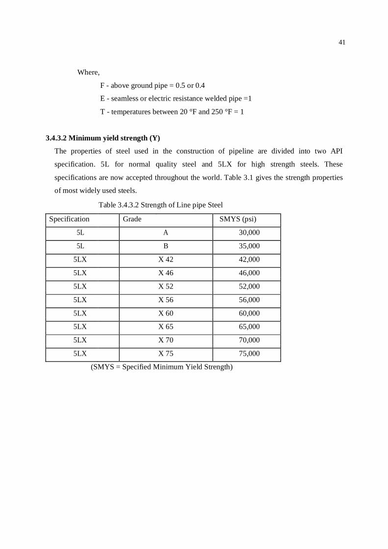
Table 3.4.3.2 Strength of Line pipe Steel
Specification Grade SMYS (psi)
5L A 30,000
5L B 35,000
5LX X 42 42,000
5LX X 46 46,000
5LX X 52 52,000
5LX X 56 56,000
5LX X 60 60,000
5LX X 65 65,000
5LX X 70 70,000
5LX X 75 75,000
(SMYS = Specified Minimum Yield Strength)

42
3.5 Headers
A header is a way to combine multi sources or multi-outlets into a single source or outlet. Headers
need to be designed to distribute the gas symmetrically. They are typically larger sized pipe, tees,
and caps. Headers are used when more than one regulator or meter run are required. In sizing
headers it is a rule of thumb that the cross sectional area of the header be 1.5 times larger than the
sum of the inlet or outlet cross sectional area (which ever is larger).
The following equation is used for header sizing
п D2/4 = [( п d12/4 + п d2
2/4+----- +п dn2/4 )*1.5] ------------------------ (3.4)
Where, п D2/4 - Cross sectional area of the header, square inches п d1
2/4 –Cross sectional area of the 1st inlet or outlet pipe line, square inches
пd22/4 - Cross sectional area of the 2nd inlet or outlet pipe line, square inches
пdn2/4 - Cross sectional area of the nth inlet or outlet pipe line, square inches
Headers may be placed above ground or below ground. One must consider noise when
placing a header above ground and liquid removal when placed below ground. A straight or
U-shaped header may be used, but it is a good idea to know the gas velocity through the
header after sizing.
3.6 Filtering system
The vessel of filters separator will be designed and manufactured in accordance with ASME
section-8, Division1 and welding the vessel with AP1-1104 Code. The followings are
important matter in order to design filter separator:
1. Permissible particle size (5 micron is allowable)
2. Filtering efficiency
3. Pressure should not be reduce with filtering operation.
Maximum gas velocity for filtering system.
Up stream filtering system : 60 feet per second
Down stream filtering system : 120 feet per second
43
3.6.1 Liquid separation system
The liquid separation system is composed by two identical filtering lines to provide separation of
liquid condensate mist from gas down stream pressure reduction . Each of them is designed for the
maximum station flow rate, so that during the normal operation of the plant one filter will be in
service and the second will be stand-by. Each filter will be put in/on of service only manually
operating through the inlet/outlet filter gear operated ball valves. The liquid separation system is
designed for the following operating condition. 3.6.1.1 Criteria of a well designed separator
To perform efficiently, a well designed separator should meet the following criteria –
Control and dissipate the energy of the well stream as it enters the separator, and
provide low enough gas and liquid velocities for proper gravity segregation and vapor-
liquid equilibrium. For this purpose, a tangential inlet to impart centrifugal motion to
the entering fluids is generally used.
Remove the bulk of the liquid from the gas in the primary separation section. It is
desirable to quickly achieve good separation at this stage.
Have a large settling section, of sufficient volume to refine the primary separation by
removing any entrained liquid from the gas, and handle any slugs of liquid (usually
known as “liquid surges”).
Minimize turbulence in the gas section of the separator to ensure proper settling.
Have a mist extractor (or eliminator) near the gas outlet to capture and coalesce the
smaller liquid particles that could not be removed by gravity settling.
Control the accumulation of froths and foams in the vessel.
Prevent re-entrainment of the separated gas and liquid.
Have proper control devices for controlling the back-pressure and the liquid level in
the separator.
Provide reliable equipment for ensuring safe and efficient operations. This includes
pressure gauges, thermometer, liquid level indicator, safety valve etc.
44
3.6.2 Filter separator design criteria
The separator sizing is depends on gas capacity, liquid capacity of separator and pressure drop
through it.
3.6.2.1 Gas capacity design of separator
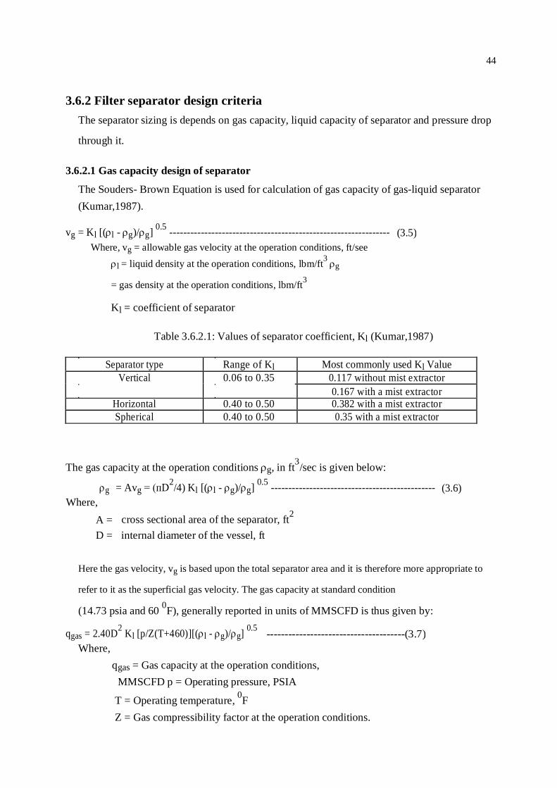
The Souders- Brown Equation is used for calculation of gas capacity of gas-liquid separator (Kumar,1987).
vg = Kl [(l - g)/g] 0.5 --------------------------------------------------------------- (3.5)Where, vg = allowable gas velocity at the operation conditions, ft/see
l = liquid density at the operation conditions, lbm/ft3 g
= gas density at the operation conditions, lbm/ft3
Kl = coefficient of separator
Table 3.6.2.1: Values of separator coefficient, Kl (Kumar,1987)
Separator type Range of Kl Most commonly used Kl Value Vertical 0.06 to 0.35 0.117 without mist extractor
0.167 with a mist extractor Horizontal 0.40 to 0.50 0.382 with a mist extractor Spherical 0.40 to 0.50 0.35 with a mist extractor
The gas capacity at the operation conditions g, in ft3/sec is given below:
g = Avg = (пD2/4) Kl [(l - g)/g] 0.5 ----------------------------------------------- (3.6)
Where,
A = cross sectional area of the separator, ft2
D = internal diameter of the vessel, ft
Here the gas velocity, vg is based upon the total separator area and it is therefore more appropriate to
refer to it as the superficial gas velocity. The gas capacity at standard condition
(14.73 psia and 60 0F), generally reported in units of MMSCFD is thus given by:
qgas = 2.40D2 Kl [p/Z(T+460)][(l - g)/g] 0.5 --------------------------------------(3.7)
Where, qgas = Gas capacity at the operation conditions,
MMSCFD p = Operating pressure, PSIA T = Operating temperature, 0F
Z = Gas compressibility factor at the operation conditions.
45
Above two Equation can be used to calculate the separator diameter required to handle a given
gas rate or to calculate the gas rate that a separator of a given size can to handle.
The area of the mist extractor Am can be obtained as follows.
Am = qg/vm --------------------------------------------------------------------------------- (3.8)Where, vm is the gas velocity through the mist extractor, determine using the first Equation
with K = 0.35 for mist extractor (wire mesh type).
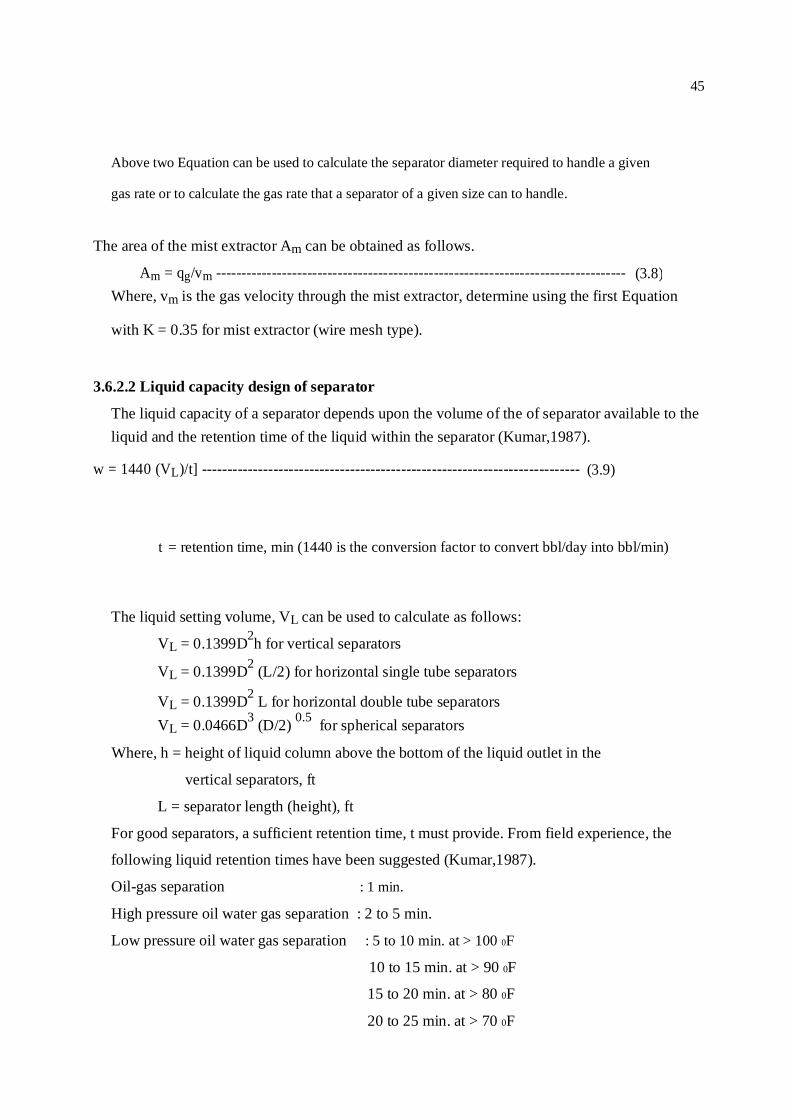
3.6.2.2 Liquid capacity design of separator
The liquid capacity of a separator depends upon the volume of the of separator available to the liquid and the retention time of the liquid within the separator (Kumar,1987).
w = 1440 (VL)/t] -------------------------------------------------------------------------- (3.9)
t = retention time, min (1440 is the conversion factor to convert bbl/day into bbl/min)
The liquid setting volume, VL can be used to calculate as follows: VL = 0.1399D2h for vertical separators
VL = 0.1399D2 (L/2) for horizontal single tube separators
VL = 0.1399D2 L for horizontal double tube separators VL = 0.0466D3 (D/2) 0.5 for spherical separators
Where, h = height of liquid column above the bottom of the liquid outlet in the
vertical separators, ft
L = separator length (height), ft
For good separators, a sufficient retention time, t must provide. From field experience, the
following liquid retention times have been suggested (Kumar,1987).
Oil-gas separation : 1 min.
High pressure oil water gas separation : 2 to 5 min.
Low pressure oil water gas separation : 5 to 10 min. at > 100 0F
10 to 15 min. at > 90 0F
15 to 20 min. at > 80 0F
20 to 25 min. at > 70 0F
46
25 to 30 min. at > 60 0F 3.6.3 Vessel design consideration
For designing separator some basic factors that must be consider are point out bellow
(Kumar,1987):
The length to diameter ratio, L/D, for a horizontal or vertical separator should be kept
between 3 and 8, due to considerations of fabrication and foundation cost.
For a vertical separator, the vapor-liquid interface (at which the feed enters) should be
at least 2 ft from the bottom and 4 ft from the top of the vessel. This implies a
minimum vertical separator length (height) of 6 ft.
For horizontal separator, the feed enters just above the vapor-liquid interface that must be
off-centered to adjust for a greater gas (or liquid) capacity as needed. The vapor-liquid
interface must be kept at 10 inch from the bottom and 16 inch from the top of the vessel.
This implies minimum horizontal separator diameter of 26 inch.

47
3.7 Regulators
The regulator is a component of the system and therefore its selection and installation should be
based on the system requirements. After these have been selected the designer must then
determine how many pressure cuts are needed to meet the design requirements. Due to large
pressure drops across the station there may be a need for multiple pressure cuts to eliminate
freezing and maintenance problems. The making of multiple pressure cuts will reduce or eliminate
noise caused by large pressure drops across a control valve. Another way to eliminate noise is to
increase the wall thickness of the piping. Next, a regulator or control valve should only be sized
for 75% of its capacity at the maximum volume and minimum inlet pressure of the station.
Properly sizing the regulator is essential to the design of the station in order to reduce
maintenance cost and operational problems.
It is recommended that regulators be installed with 5 pipe diameters upstream and 8 pipe
diameters downstream. This will allow time for the control valve or regulator to sense and
react to a change in the process.
The selection of a regulator requires some consideration of the following
• Maximum volumes
• Site location
• Operation and Maintenance
• Environmental impact
• Safety
The first step in selecting a regulator is to know what type of control is desired • Volume • Pressure
The second step is to determine what type of regulator is needed
• Spring operated
• Pilot operated
• Controller operated
In the RMS both axial flow valve (AFV) and on line maintenance type regulators are used .

48
Figure 3.7: Regulators with comperssore machine
3.7.1 Regulators installed
It is recommended that regulators be installed with 5 pipe diameters upstream and 8 pipe
diameters downstream (AGA Report 7). This will allow time for the regulator to sense and
react to a change in the process.
3.7.1.1 Parallel installation of regulators
Although many regulator designs can operate over a wide flow and pressure range often it is
necessary to consider parallel runs to provide proper control. A regulator required to operate
nearly closed over long periods of time will have more valve and seal damage than a unit that
is sized to have the valve open at least ten percent. A small regulator can be installed in the
one line to handle low flows and a large regulator installed in the parallel line to handle large
flows up to the required capacity for the station. Good practice would also dictate the use of
49
parallel regulators for the purpose of redundancy. Since there are different types and sizes of
regulators.
3.7.1.2 Pressure sensing point
All regulators have a pressure sensing point and those with an external control line should have a
sensing pressure tap several pipe diameters downstream of the regulator on a straight run of pipe.
Each regulator should have a separate sensing tap and control line. A common practice is to use
ten pipe diameters downstream for the sensing pressure tap with five pipe diameters usually
considered to be minimum. The control line may be ¼ inch, ½ inch or ¾ inch pipe or tubing,
depending on the type of regulator and the distance from the pressure sensing point to the
regulator. Long sensing lines should be adequately supported and should slope slightly toward the
point of connection to the pipe. Pressure taps should not be located on elbows, expanders or other
fitting that would introduce false or unstable pressure registration. At the pressure sensing
connection, a valve should be installed to enable isolation of the sensing line, thus permitting the
regulator to be taken out of service without shutting down the station. In addition to the sensing
line connection, another tap with a valve for checking or recording pressure should be located as
near as possible to the sensing line connection. A single tap with a tee can be used to provide the
attachments.
50
3.7.2 Inlet and outlet connections
The piping to and from regulator should be supported adequately to minimize pipe strains. The
piping should be designed to have adequate capacity for the expected maximum flow and the
pressure conditions. Velocities in regulator valve passages can reach sonic velocity conditions.
High velocities create noise so piping should be sized to keep gas velocities at a reasonable level.
There are specific pipeline velocity limits used by many companies to maintain a relatively quiet
pipeline system and to keep pressure losses low. Such limiting velocities range between 50 feet
per second to a maximum of approximately 400 feet per second. There are situations where higher
velocities may be required for short distances; however, the designer should calculate the pipe
velocities to be encountered and determine the steps that may be necessary to maintain
satisfactory noise levels.
3.7.2.1 Regulator sizing
The following must be consider in order to sizing regulator :
Inlet pressure
Outlet pressure
Gas flow rate
Over pressure protection device such as monitor, relief valve and slam shut valve
No. of pressure staging.
Two Equations are used for sizing regulator all over the world :
1.Universal gas sizing Equation and
2. ISA gas sizing equation.
ISA gas sizing equation is more precisely used for pressure control valve. But Universal gas sizing
Equation is popular in natural gas industries. This Equation is described as follows:
1. Subsonic Flow (P1- P2/ P1 0.55)
Cg = Q/ P1[ 520/GT sin [(3417/C1)(P1- P2)/P1] Degrees --------------------------- (3.10)
2. Sonic Flow (P1- P2/ P1 0.55)
Cg = Q/ (P1*1.29) ----------------------------------------------------------------------- (3.11)
51
Where,
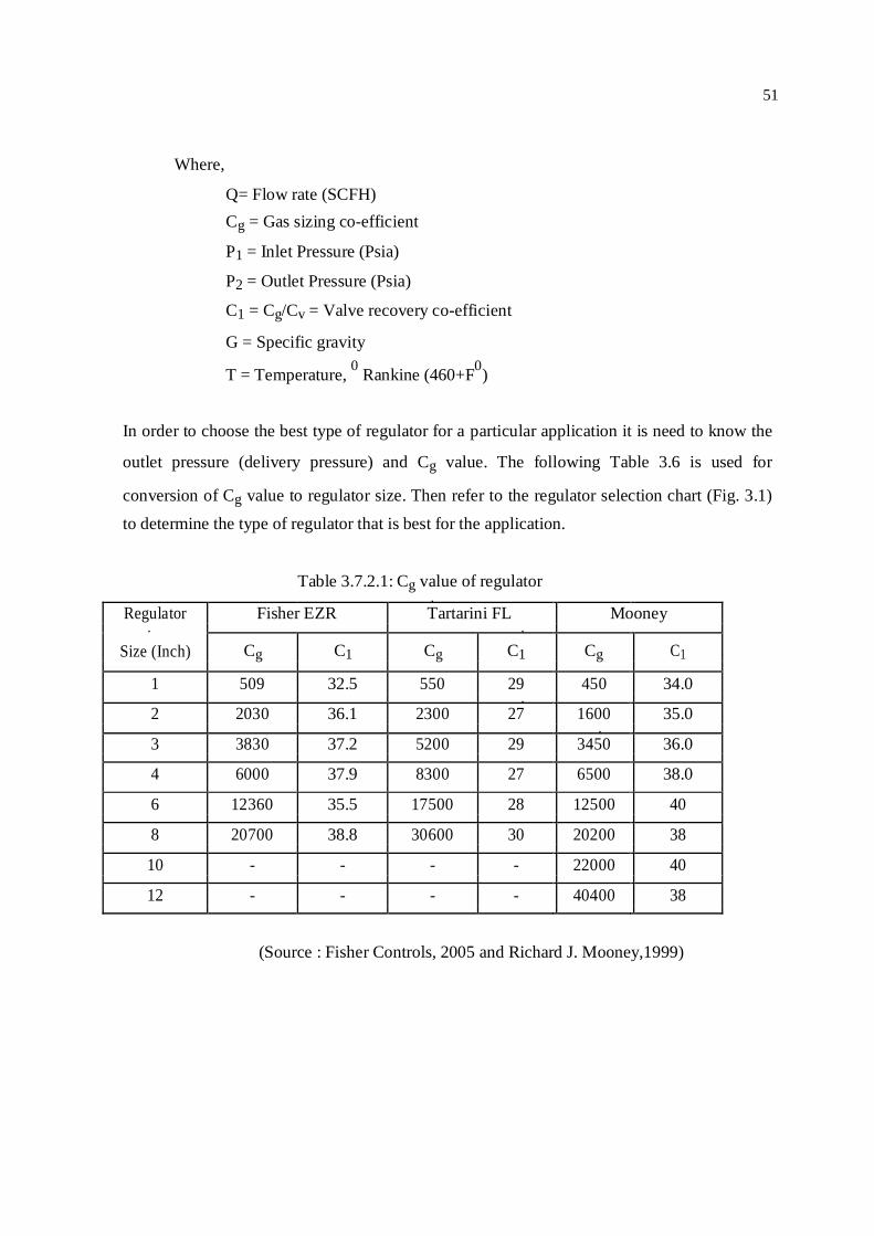
Q= Flow rate (SCFH) Cg = Gas sizing co-efficient P1 = Inlet Pressure (Psia) P2 = Outlet Pressure (Psia) C1 = Cg/Cv = Valve recovery co-efficient
G = Specific gravity
T = Temperature, 0 Rankine (460+F0)
In order to choose the best type of regulator for a particular application it is need to know the
outlet pressure (delivery pressure) and Cg value. The following Table 3.6 is used for
conversion of Cg value to regulator size. Then refer to the regulator selection chart (Fig. 3.1) to determine the type of regulator that is best for the application.
Table 3.7.2.1: Cg value of regulator
Regulator Fisher EZR Tartarini FL Mooney
Size (Inch) Cg C1 Cg C1 Cg C1
1 509 32.5 550 29 450 34.0
2 2030 36.1 2300 27 1600 35.0
3 3830 37.2 5200 29 3450 36.0
4 6000 37.9 8300 27 6500 38.0
6 12360 35.5 17500 28 12500 40
8 20700 38.8 30600 30 20200 38
10 - - - - 22000 40
12 - - - - 40400 38
(Source : Fisher Controls, 2005 and Richard J. Mooney,1999)
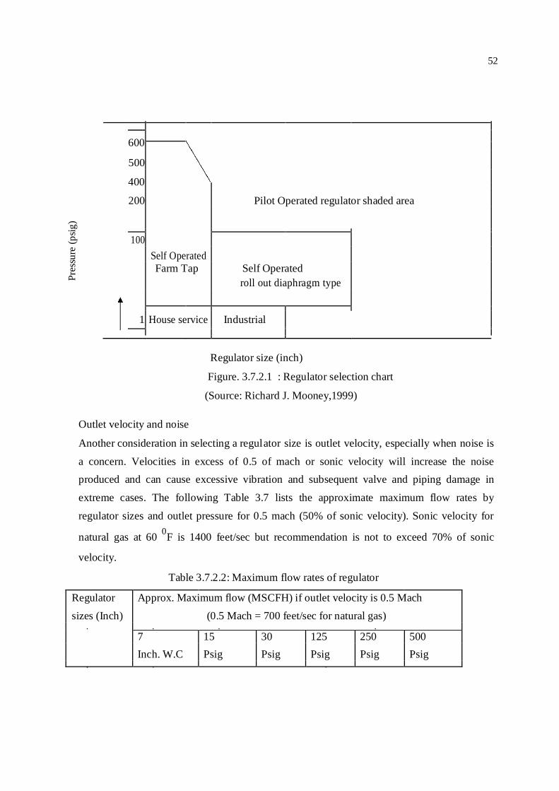
52
Pres
sure
(psig
)
600
500
400
200 Pilot Operated regulator shaded area
100
Self Operated
Farm Tap Self Operated
roll out diaphragm type
1 House service Industrial
Regulator size (inch)
Figure. 3.7.2.1 : Regulator selection chart
(Source: Richard J. Mooney,1999)
Outlet velocity and noise
Another consideration in selecting a regul ator size is outlet velocity, especially when noise is
a concern. Velocities in excess of 0.5 of mach or sonic velocity will increase the noise produced and can cause excessive vibration and subsequent valve and piping damage in
extreme cases. The following Table 3.7 lists the approximate maximum flow rates by
regulator sizes and outlet pressure for 0.5 mach (50% of sonic velocity). Sonic velocity for
natural gas at 60 0F is 1400 feet/sec but recommendation is not to exceed 70% of sonic
velocity. Table 3.7.2.2: Maximum flow rates of regulator
Regulator Approx. Maximum flow (MSCFH) if outlet velocity is 0.5 Mach
sizes (Inch) (0.5 Mach = 700 feet/sec for natural gas)
7 15 30 125 250 500
Inch. W.C Psig Psig Psig Psig Psig
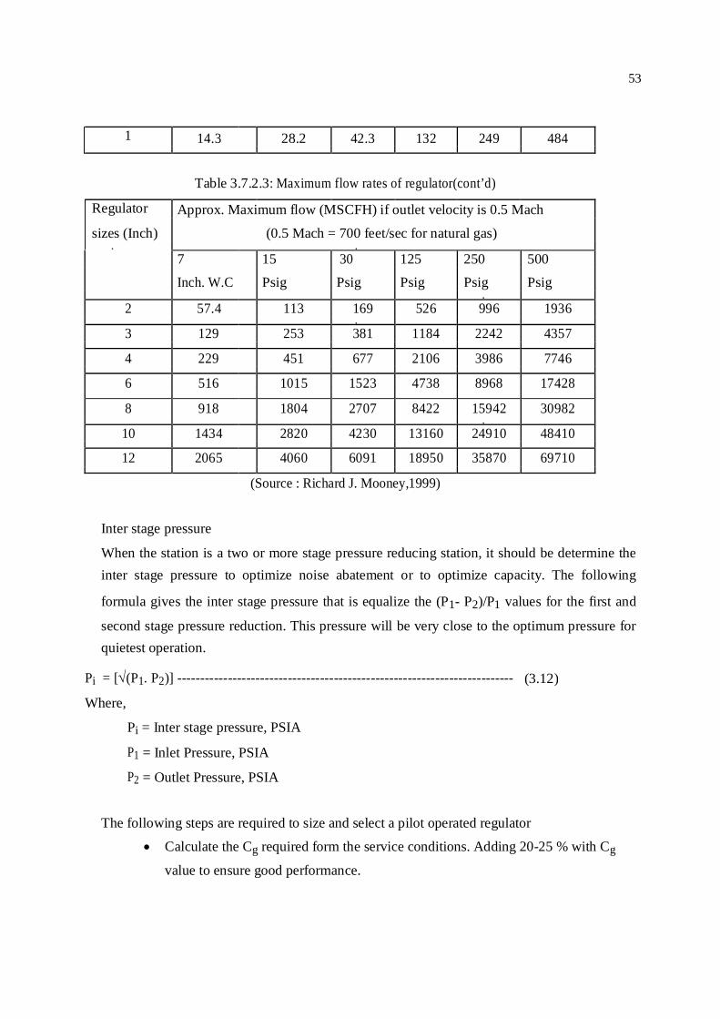
53
1 14.3 28.2 42.3 132 249 484
Table 3.7.2.3: Maximum flow rates of regulator(cont’d)
Regulator Approx. Maximum flow (MSCFH) if outlet velocity is 0.5 Mach
sizes (Inch) (0.5 Mach = 700 feet/sec for natural gas)
7 15 30 125 250 500
Inch. W.C Psig Psig Psig Psig Psig
2 57.4 113 169 526 996 1936
3 129 253 381 1184 2242 4357
4 229 451 677 2106 3986 7746
6 516 1015 1523 4738 8968 17428
8 918 1804 2707 8422 15942 30982
10 1434 2820 4230 13160 24910 48410
12 2065 4060 6091 18950 35870 69710
(Source : Richard J. Mooney,1999)
Inter stage pressure
When the station is a two or more stage pressure reducing station, it should be determine the inter stage pressure to optimize noise abatement or to optimize capacity. The following
formula gives the inter stage pressure that is equalize the (P1- P2)/P1 values for the first and
second stage pressure reduction. This pressure will be very close to the optimum pressure for quietest operation.
Pi = [(P1. P2)] ------------------------------------------------------------------------- (3.12)
Where,
Pi = Inter stage pressure, PSIA
P1 = Inlet Pressure, PSIA
P2 = Outlet Pressure, PSIA
The following steps are required to size and select a pilot operated regulator Calculate the Cg required form the service conditions. Adding 20-25 % with Cg
value to ensure good performance.

54
Dividing the Cg value by 0.70 or multiplying by 1.43 to determine the size of
monitor and active regulator. Because when two regulators are used in series their
capacity is approximately 70% of a single regulator of the same size.
Select a body class rating for the inlet pressure requirements. Select a body size based on published Cg values or sizing tables.
Select a pilot pressure range for the outlet pressure desired.
3.7.2.2 Pressure setting
Regulator can be used as a single or jointly as Active-Monitor. The relief valve is installed at
outlet portion of the regulating run. The setting pressure of relief valve is higher than regulator
pressure. The setting of Active regulator, monitor regulator, relief and shut off valve are
described as follows:
Active Regulator = X psig
Monitor Regulator = (X +5% of X) psig
Relief valve =(X +10% of X) psig
Slam shut off valve = (X +20% of X) psig
3.8 Heating capacity of gas heater
The heaters are designed on the basis of maximum inlet pressure, maximum outlet pressure,
minimum inlet temperature and maximum flow expected after ten years of installation. Heat
(Enthalpy) required to rise up the temperature of a specific density gas with different pressure
is the main criteria of heater design. For a gas of specific density , (kg/m3); flow rate, Q(m3/s) and enthalpy change, E (kJ/kg) for rise up temperature to two different pressure, rate
of heat absorption, W (kJ/s or kw) is written (Roy,1989) by.
W = E.Q. -------------------------------------------------------------------------- (3.13)
Heat required for preheating the natural gas can also be calculated by using the Joule-
Thomson effect Equation (McAllister,1998).
W = qn.t gas.n.Cp ----------------------------------------------------------------- (3.14)
Where, W = heat quantity, kJ/h qn = gas volume or flow rate, m3/h
t gas = total temperature = t1+ t2 in K
55
t1= Joule-Thomson effect = (Pi – Po) 0.5 in K
t2 = temperature different between minimum gas inlet temperature and
temperature required after gas pressure reduction in K
n = Specific density of natural gas, kg/m3
Cp = Specific heat of natural gas, kJ/kg
Pi = Inlet pressure of natural gas, bar Po= Outlet pressure of natural gas, bar
On the basis of the heat required to rise up the temperature of gas a suitable capacity heater is
designed. The vessel size of heater will be design in accordance with ASME section 8,
Devission-1.
3.9 Meter selection
For custody transfer application, it is very important to select a proper meter considering the
load nature of the RMS. In regulating & metering station design, both orifice and turbine
meters are used. The orifice meter is simple, accurate, relatively inexpensive rugged and
reliable but hence a limited rangebility (3:1) and are difficult to adapt to automation. For this
reason very low and very high quantity of volume are not measured by the same orifice plate.
Low quantity of volume is measured by small size of orifice plate. Accuracy and rangebility
(20:1) is very high for turbine meter.
3.10 Optional short-coupled installation
In those instances where the required space for the recommended installation of Figure 3.4 is not
available, a short-coupled installation may be employed as shown in Figure 3.5 This configuration
utilizes minimum of four nominal pipe diameters upstream with straightening vanes located at the
inlet of piping. The distance between the straightening vane outlet and the meter inlet should be a
minimum of two nominal pipe diameters. The meter is connected to the vertical risers using a
standard Tee or elbow. The maximum pipe reduction to the risers is one nominal pipe size,
valving, filters or strainers may be installed on the risers.

56
Figure 3.10: Short coupled installation of an in-line gas turbine meter (Minimum Length) 3.11. Straightening vanes
The purpose of a straightening vane is to eliminate swirls and cross currents set up by the pipe
fitting valves or regulators preceding the meter inlet piping. While the specifications which
follow up particularly to the type of vanes shown in figure 3.6, vanes of other designs can be
used if they meet the specifications.
In construction of vanes the maximum transverse dimension, “a” of any passage through the
vane should not exceed one- fourth the inside diameter, “D” of the pipe. Also the cross
sectional area, “A” of any passage within the assembled vanes should not exceed one-
sixteenth of the cross sectional area of the containing pipe. The length, “L” of the vanes
should be at least 10 times the maximum inside dimension, “a”.
The vanes may be built of standard weight pipe or thin- walled tubing either welded together
securely attached into the meter inlet piping or mounted into two end-rings small enough to
slip in the pipe. Square, hexagonal or other shaped tubing may be used in making the vanes. It
is not necessary that the vane passages be of the same size, but their arrangement should be
symmetrical.
Figure 3.11. Straightening Vanes
(Source : AGA Report 7)

57
3.12 Strainers or Filters
Foreign substances in a pipe line can cause serious damage to turbine meters. Strainers are
recommended when the presence of damaging foreign material in the gas stream can be
anticipated. Strainer should be sized so that at maximum flow there is a minimum pressure
drop and flow distortion.
A greater degree of meter protection can be accomplished through the use of dry-type or
separator type filter installed upstream of the meter inlet piping. It is recommended that the
differential pressure across a filter be monitored to maintain it in good condition so as to
prevent flow distortion and possible customer outage.
3.13. Over-range protection
Sudden rotor over speeding caused by extreme gas velocities encountered during pressuring m,
venting or purging can cause sever damage. Some meters and readout devices may be damaged
when they are run backwards. Therefore, the pressure blow-down valve should be located
downstream of the meter. While turbine meters can be operated up to 150% of rated capacity with
no damaging effects for short period of time, over-sized blow-down valves can cause rotational
speeds greatly in excess of this amount. Therefore, the blow-down valve should be sized as
follows (Source: AGA Report No.7):
Meter run Valve size
2 1/4
3 1/2
4 1/2
6 1
8 1
12 1
As a rule of thumb, the blow-down valve should not be larger than one-sixth of the meter size.
In those installations where adequate pressure is available, either a critical flow orifice or
sonic venture nozzle may be installed in the piping downstream of the meter and should be
sized to limit the meter to approximately 120% of its maximum rated capacity. A critical flow
orifice so designed will result in a 50% permanent pressure loss and a sonic venture nozzle
will in a 10-20% permanent pressure loss.
58
3.14 By- pass
It is good practice to provide a by-pass so the meter can be maintained and calibrated without
a service interruption. This should include proper valving relative to the type of calibrating
equipment to be used.
3.14.1 Additional installation requirements
The meter and meter piping should be installed so as to reduce strain due to pipeline
stresses.
A concentric alignment of the companion pipe flanges with the meter inlet and outlet
connections should be obtained. This concentric alignment will eliminate any
appreciable effect upon the meter accuracy that might be caused by an offset in the
internal diameters that may occur in some installations.
A gasket protrusion into the bore or flow pattern at the meter connections should not
be permitted.
Pipe interior should be of commercial roughness, and the flange I.D. should be the
same as that of the pipe. Welds on piping at the meter inlet and outlet should be
ground to the I.D of the pipe.
Installations where liquid can be encountered should be designed to prevent liquid
accumulation in the meter.
No welding should be done in the immediate area of the meter to prevent possible
internal meter damage.
3.15 Accessory installation Accessory devices used for integrating uncorrected volume to base conditions or for recording
operating parameters must be properly installed and their connections made as specified
herein.
3.15.1 Temperature measurement
59
Since upstream disturbances should be kept to a minimum, the recommended location for a
thermometer well is downstream of the meter. It should be located within five pipe diameters of the
meter outlet and upstream of any valve or flow restrictor. The thermometer well should
be installed to insure that the temperature is not influenced by heat transfer from the piping
and well attachment.
3.15.2 Pressure measurement
A pressure tap as provided by the manufacturer on the meter body should be used as the point
of pressure sensing for recording or integrating instruments.
3.15.3 Density measurement
In the use of densitometers, while it is desirable to sample the gas as close as possible to the
rotor conditions, care must be exercised not to disturb the meter inlet flow or to create an un
metered by-pass. Reference should be made to manuals on the various densitometers for
further information.
3.16 Flow conditions:
The pipe line or installation conditions, which can be made up of a number of variables can
have a major influence on the operation and accuracy of an orifice plate metering system. It is
very important to understand the influence of these variables for accurate flow measurement
through orifice or turbine meter. Before the fluid measurement process is initiated, some
fundamental characteristics of fluid to be measured and most common field conditions must
be determined. Some of these are as follows:
Velocity profile and distortion
Swirl
Reynolds number
That fluid is Newtonian in behavior
the composition
influence and/or presence of foreign material

60
CHAPTER 4
GAS LOAD CALCULATION
4.1 Gas source
The location of the proposed 50 MW Power plant is at Sreepur in Gazipur district. A
4"DN×500 psig Off take point of Dhanua TBS exists at a approximate distance of 0.5 km
from the plant site. The Dhanua TBS is presently receiving gas through Monohordi-
Elenga 24" DN ×1000 psig pipe line (Appendix O). A 0.5 km 4" DN ×500 psig pipe line
can be constructed to transmit gas to the Power plant through the RMS at a required
quantity and pressure.
A schematic line diagram of 4" DN ×500 psig pipe line network from Dhanua TBS to
power plant RMS is shown in Fig 4.1. 4" DN ×500 Psig Pipe
60 Psig Line
Pipe Line From off take Point
Power Plant Dhanua
50 MW
RMS TBS Power plant
24" DN ×1000 Psig Monohordi–Elenga
Pipe Line
Figure 4.1. Schematic diagram of 4" DN ×500 psig pipe line
4.2 Gas based Power Plant
Bulk electric power is produced by special plants known as generating stations or power plants. A
generating station essentially employs a prime mover coupled to an alternator for the production
of electric power. Depending upon the form of energy converted into electrical energy, the power
plants are classified various classes such as Steam power plants, Hydro- electric power plants,
Diesel power plants and Nuclear power plants. The
61
Power Generating Station that generate electricity by using natural gas is called gas based
Power Plants. These type of Power Plants are Gas Turbine, Steam Turbine and gas generator. 4.2.1 Gas load for 50 MW power plant
The proposed power plant considered as gas based power plant has an installed capacity
of 50 MW. The plant will produce electricity using gas generators. Six gas generators,
each having 8.425 MW capacity will be required for the power plant.
Considering Rolls-Royce generator for proposed power plant, the required data is
given as follows (Appendix D).
Engine Type- B 35 :40 V 20 AG
Generating capacity of each generator = 8425 KW or 8.425 MW (Mega watt)
Thermal overall efficiency = 42 %
Fuel type = Natural gas
Minimum gas feed pressure to engine inlet = 50 Psig
Gas feed temperature to engine inlet = 20 0C
Lower calorific value of natural gas = 915 Btu/SCF (Appendix C)
For 50 MW power generation = 50/8.425 = 6 (Six) generating sets are required
The gas load for 50 MW power plant is calculated is as follows:
Gas load calculation on the basis of electrical output :
Electrical output of each generator = 8425 KW
Heat input of each generator = 8425/0.42 KW (Thermal overall efficiency, η = 42%)
= 20060 KW
Input heat of each generator = (20060X1000)W
= (20060X1000) Joule/See
= [(20060X1000)/4.2] Cal/See
= [(20060X1000)/(4.2X252)] Btu/See
= [(20060X1000 X3600)/(4.2X252)] Btu/hr
= 6,82,31,293 Btu/hr
62
Lower calorific value of natural gas = 915 Btu/SCF (Appendix C)
Gas required for each generator = (6,82,31,293/915) SCFH
= 74,570 SCFH
= 1.8 MMSCFD
Gas required for 6 (Six) generators = 1.8 X 6 MMSCFD =11
MMSCFD
Therefore, the gas consumption for the 50 MW power plant is 11 MMSCFD.
The selected type of gas generators requires minimum 50 psig pressure for their
operation. Therefore, the total gas will be required around 11 MMSCFD at pressure of
above 50 psig for the power plant.
For designing, the gas flowing capacity of the RMS should be consider as the sum of
power plant consumption, heater RMS consumption and decreasing the efficiency of the
power plant.
From the above discussion, it is recommended 10% additional load for RMS design.
Assume, 10% additional load for RMS design
The gas flowing capacity of the RMS = 11 MMSCFD*1.1 = 12 MMSCFD
From the data, it is seen that the maximum flowing capacity of the RMS is 12 MMSCFD
and the minimum flowing capacity of the RMS is 1.8 MMSCFD. Therefore, the turn
down ratio of the RMS is 12:1.8, which should be consider for proper size selection of
the RMS equipments.
63
CHAPTER 5
SAFETY AND ENVIRONMEMTAL ASPECT OF RMS
Safety and environmental impacts are the first considerations in the design of regulating
and metering station. Many factors must be considered in the design to ensure safety of
pipeline and RMS operation.. International codes and standards (ASTM, ASME, ANSI,
API), A.G.A. Report no-7 and Bangladesh natural gas safety rules,1991(Amendment
2003) have been followed for design of gas pipelines and RMS. In this chapter, safety
and environmental aspects in designing a regulating and metering station will be
discussed.
5.1 Environmental impacts of proposed gas facilities for the power plant
The impacts of a gas facilities project can be direct, such as the effect of toxic discharge
on air, noise and water quality or indirect, such as the effect on human health from
exposure to particulates or contaminants. It increases the possibility of explosion and
leakage due to accidents, malfunction of joints or corrosion and lack of skillness and
carefulness of related persons. These negative effects on the environment will be
negligible due to implementation of the project.
Taking proper precautions, these negative effects can be mitigated. The positive impacts
of the project will out weigh the negative one.
The negative impacts of the power plant are much more compared to that of RMS and
pipeline. Running of power plant will produce more noise, vibration, wear and rear
compared to RMS, so more protection should be taken to reduce the negative impacts of
power plant. The negative impacts of RMS and pipeline are less likely.
64
5.2 Environmental Consideration
For environmental reasons in additional to the necessary reliability the station should be of the
smallest practicable size with a high degree of safety against leakage and as silent as possible in
operation. The generated sound level shall not exceed 85dBA (DoE Report,1991). In this regard,
all of the equipments and instruments have been selected as per ASTM, ASME, ANSI, API,
A.G.A. Report no-7 and Bangladesh natural gas safety rules,1991 (Amendment 2003), so
that sound level dose not exceed 85dBA .
5.3 Safety Consideration
In order to enhance the occupational health and works safety of gas pipeline and RMS
project, the following monitoring works have been done.
5.3.1 Gas quality
Gas quality should be maintained to minimize the possibility of any kind of corrosion,
wear and tear, burning quality, so gas should be dust, water and sulfur free. In this view,
liquid separator, filter separator and heater have been used to maintain the gas quality of
the proposed RMS.
5.3.2 Wall thickness of pipe
Pipe is selected with sufficient wall thickness or installed with adequate protection to
withstand anticipated external pressures and loads that will imposed on the pipe after
installation. Due consideration is given to the safety of life and property while selecting a
valve and pipe. For this purpose the American code (ASME B 31.8) has been followed.
5.3.3 Pressure rating of materials
Considering the safety and environmental aspects, the pressure rating of RMS materials have
been selected as per maximum allowable operating pressure in accordance with National
Standards Institute (ANSI) pressure class and API (Appendix H, I).
5.3.4 Control of overpressure in the system
To prevent personal injury, equipment damage or leakage due to bursting of pressure-
containing parts, it is necessary to install adequate overpressure protection when installing a
pressure reducing regulator. Overpressure protection equipment should be installed to protect
all downstream equipments in the event of regulator failure.
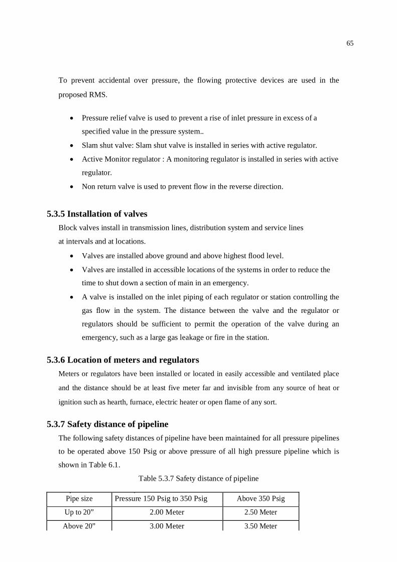
65
To prevent accidental over pressure, the flowing protective devices are used in the
proposed RMS.
Pressure relief valve is used to prevent a rise of inlet pressure in excess of a
specified value in the pressure system..
Slam shut valve: Slam shut valve is installed in series with active regulator.
Active Monitor regulator : A monitoring regulator is installed in series with active
regulator.
Non return valve is used to prevent flow in the reverse direction. 5.3.5 Installation of valves
Block valves install in transmission lines, distribution system and service lines
at intervals and at locations.
Valves are installed above ground and above highest flood level.
Valves are installed in accessible locations of the systems in order to reduce the
time to shut down a section of main in an emergency.
A valve is installed on the inlet piping of each regulator or station controlling the
gas flow in the system. The distance between the valve and the regulator or
regulators should be sufficient to permit the operation of the valve during an
emergency, such as a large gas leakage or fire in the station.
5.3.6 Location of meters and regulators
Meters or regulators have been installed or located in easily accessible and ventilated place
and the distance should be at least five meter far and invisible from any source of heat or
ignition such as hearth, furnace, electric heater or open flame of any sort.
5.3.7 Safety distance of pipeline
The following safety distances of pipeline have been maintained for all pressure pipelines
to be operated above 150 Psig or above pressure of all high pressure pipeline which is
shown in Table 6.1.
Table 5.3.7 Safety distance of pipeline
Pipe size Pressure 150 Psig to 350 Psig Above 350 Psig
Up to 20” 2.00 Meter 2.50 Meter
Above 20” 3.00 Meter 3.50 Meter

66
67
5.3.8 Controlling Hazards
Some control measures to prevent hazards are as follows:
Marking hazards with signs, flags, lights, alarms, barricades, fences, labels,
placards or other materials.
Providing personal protective and other safety equipments to workers.
Using engineering controls to reduce the impact of hazards.
Whenever possible, hazards should be eliminated. If elimination is not possible, other
control measures should be used to protect workers.
5.3.9 Prevention of eddy current
Insulating joints (IJ) have been used at station inlet and outlet of RMS to protect eddy current
producing from transmission and distribution network that may damage the RMS.
5.3.10 Leak detector
Pipe line leak detectors should be used in the gas system. Generally odorant is used to
detect the line leakage. A leak detector is suggested for the proposed RMS.
5.3.11 Fire Extinguisher
There is a provision of fire extinguisher in the RMS premises for controlling of small
fires due to leakage of gas.
5.3.12 Protection against corrosion
Natural gas pipelines are laid below the ground surface. These pipelines are susceptible to
corrosion by various subsoil environments. As the pipelines are growing old, it is becoming
more difficult to protect them from the damage caused by corrosion. Major cause of the
supply interruptions is leakage in the pipeline due to corrosion. To control corrosion of
pipeline combined system of coating and cathodic protection should be used. Within one year
of construction of pipeline, cathodic protection is applied to the pipeline in accordance with
BS CP 1021 or American National Association of corrosion Engineers code RP 01-72 as far
as practicable.
68
A safe and leak free pipeline network is essential for uninterrupted gas supply to the
power plant. For this reason a Cathodic Protection (CP) station is recommended for the
0.5 km 4" DN ×500 psig pipe line network of the power plant RMS within one year of
the construction of the pipeline.
5.3.13 The lighting arrangement
The lighting arrangement for the RMS area should be explosion proof and suitable for
hazardous area. Lighting fixtures are mounted on a pole above the suitable height for
proper illuminations.
5.3.14 Major activities of a Project
The major activities of a gas facilities project are pipeline routes survey, Clearance from
DOE, Design and Drawing, procurement of materials, construction, fabrication and
installation, testing, Tie-ins with live line and Commissioning.
Hydrostatic test
Hydrostatic test is performed after mechanical completion of the pipeline. For hydrostatic
test, water is poured into the pipeline section. Then the pipeline is pressurized by
injecting small amount of water through hand pump. As per API standard minimum
hydrostatic test pressure should be 1.5 times of design pressure.
Commissioning of pipeline and facilities
Commissioning is the flowing of natural gas through the newly constructed pipeline for
first time. Pipeline, valves, fittings, meters and regulators are checked and rectified if
necessary before Commissioning.
69
CHAPTER 6
CONCLUSIONS AND RECOMMENDATIONS
6.1. Conclusions
Based on the objectives of this project to design an ideal gas Regulating and Metering
Station and cost estimation of the project, the following conclusions are made from this
study.
Gas flow capacity, maximum inlet pressure and outlet pressure of the RMS are 12
MMSCFD, 500 psig and 60 psig respectively for uninterrupted gas supply to the
50 MW power plant.
In this project work, fluid characteristics, process data, gas safety rules,
International codes and standards (ASTM, ASME ANSI, API) have been
followed for proper design.
All the equipments of Regulating and Metering station have been selected and
arranged as per internationally recommended standards (IGE TD 9, AGA 7 and API )
maintaining the entire requirements for filtering, regulating, metering to prevent
various operational difficulties and measurement error.
The pipe and fittings have been chosen in such a way that turbulence can be
avoided or made minimum.
Meter type and size have been selected considering variation of flow rate and
pressure to measure the gas volume accurately because the revenue earning for
the company is related to measurement.
The RMS has been proposed to be well furnished with modern flow computer for gas
measurement and online gas chromatograph for continuous gas analysis for smooth,
quantitative and accurate measurement of gas flow.
Variation in different variables such as inlet pressure, specific density, specific
heat, compressibility factor and heating value within the allowable limit do not
require any change in the proposed design.
70
The cost estimation of the project has been calculated on the basis of
preconstruction expenditure, construction cost, material cost etc. The total cost of
the project is estimated as Tk. 494.463 Lakh.
71
6.2 Recommendations
A Regulating and Metering station should be designed to meet the present and
future demand under variable gas flow and pressure conditions and decreasing
efficiency of the power plant.
The RMS should be kept under a SCADA system for remote controlling of the
system such as the valves, regulators and also for monitoring the status of flow
rate and pressure for the case of operation as per international practice of the gas
industry.
After construction of the pipe line of RMS, cathodic protection (CP) system
should be installed in the pipeline network and RMS for safe and leak free
network in accordance with the requirements of British standard specification
code BS CP 1021 or American National Association of Corrosion Engineers code
RP 01-72.
RMS equipments, piping and inlet outlet direction of gas flow should be painted
as per colour coding of pipes and equipments.
Before commissioning of the pipeline and RMS, both the pipeline and RMS
should be tested by means of standard hydrostatic test for ensuring the safety and
integrity of the pipeline and RMS.

72
REFERENCES
[1] AGA Report Part Nine : ‘Design of Meter and Regulator Stations’ Operating section
American Gas Association 1515 Wilson Boulevard Arlington, Virginia 22209, U.S.A.
[2] AGA Report Number-7: Measuring of fuel gas by Turbine meters’ Operating section
American Gas Association 1515 Wilson Boulevard Arlington, Virginia 22209, U.S.A.
[3] AGA Report Number -3: Orifice Metering of Natural Gas and other related
hydrocarbon’ Operating section American Gas Association 1315 Wilson
Boulevard Arlington, Virginia 22209, U.S.A.
[4] ASME B 31.8 (1995): ‘Gas and Transmission and Distribution Piping System’.
[5] API Specification 6D (1994), ‘Specification for Pipeline Valves’, Washington,
[6] API Specification 5L(1991) ‘Specification for Line pipe’, Washington, DC 20005.
[7] C. Richard Sivalls, P.E(1987), ‘Oil and gas separator design manual’, Sivalls,
Inc. Odessa, Texas, U.S.A.
[8] DOE Report (1991), ‘Environmental Quality Standards for Bangladesh’, Published by
Department of Environment, Dhaka.
[9] DOE (1997), EIA Guide Lines for Industries, Department of Environment, Ministry of
Environmental and Forest, Government of Peoples Republic of Bangladesh.
[10] Fisher Controls, (2005), ‘Natural Gas Regulators Application Guide’,
Fisher Controls International Inc,U.S.A.
[11] GTCL (2007): ‘Report on High Pressure Transmission Lines’, Operation Division.
[12] IGE/TD/9 : ‘Recommendations on Transmission and Distribution Practice, for off take
and pressure Regulating Installations for inlet pressure between 7 and 100 bar’ The
Institution of Gas Engineers, 17 Grosvenor crescent, London SW1X7E
[13] Instromet, (2001), ‘Turbine Gas Meter Handbook’ Instromet Inc, Houston, Texas.

73
[14] ISO 14001, (2004), ‘Standard for International Environmental Management
System’, Geneva, Switzerland.
[15] ISO 5168, (2005), ‘‘Procedures for the Evaluation of Uncertainties’,Geneva, Switzerland.
[16] Kumar, S. (1987), ‘Gas Production Engineering’, Gulf Publishing
Company. Houston, Texas, U.S.A.
[17] Mc.Allister, E.W. (1998), ‘Pipe Line Rules of Thumb Handbook’ Gulf
Publishing Company, Houston, Texas, U.S.A.
[18] Natural Gas Safety Rules of Bangladesh, 1991(Amendment 2003), Published by the
Ministry of Energy and Mineral Resources, Government of Bangladesh.
[19] OHSAS 18001, (2007), ‘Standards for Occupational Health and Safety
Management Systems’.
[20] Parker, M.E, (1954) “Pipeline Corrosion and Cathodic Protection”, First Edition, Houston, Texas.
[21] Roy, K. R. (1989), ‘A survey of the processes entailed in the design of natural
gas regulating stations in United Kingdom’, Department of Mechanical and
process Engineering, University of Strathclyde, U.K.
[22] Richard J. Mooney (1999), ‘Regulator sizing and selection’ Mooney Controls Inc.
[23] RMG, (2008), ‘Turbine Gas Meter Catalogue’ RMG-GmbH, Germany.
[24] Rolls-Royce (2006),‘Gas Engine Catalogue’, Bergen, Norway.
[25] Sercks Controls (2004),’ Bangladesh Gas Infrastructure Development
Project-SCADA Component’, Sercks Controls Ltd.
[26] Shanghai Fiorentini (2008),‘ Filter Separators Catalogue’ Shanghai Fiorentini
Gas Equipment Company Ltd, Shanghai, China.
[27] TGTDCL (2003), ‘Report on Environmental Safety’, Planning Department.
[28] TGTDCL (2007-2008): ‘Annual Report’, Titas Gas Transmission and
Distribution Com. Ltd.