D-90 TYPEDE DOUBLEENVELOPING WORMGEAR SPEEDREDUCERS...
100
D - 90 ® TYPEDE ® DOUBLE ENVELOPING WORM GEAR SPEED REDUCERS HIGH EFFICIENCY–HIGH TORQUE ® CATALOG 190I
Transcript of D-90 TYPEDE DOUBLEENVELOPING WORMGEAR SPEEDREDUCERS...

D-90 ®TYPEDE ®
DOUBLE ENVELOPINGWORMGEAR SPEED REDUCERS
HIGH EFFICIENCY–HIGH TORQUE
®
CATALOG 190I

D-90 ®TYPEDE ®
WINSMITH®’S NEW DOUBLE ENVELOPINGWORM GEAR REDUCERS
HIGH POWER—HIGH EFFICIENCY—COMPACT DESIGN
WORM SHAFTHeat-treatedalloy steel worm.
DUAL CONTACTMESHTwo separate contact paths at the mesh reducescontact pressure, increasestooth contact and powerdensity.
BEARINGSTapered roller bearings on bothinput (worm) shafts and outputshafts provide maximum thrustand overhung load capacity andassure long service life.
GEARSHigh gradecentrifugallycast or chill cast bronze.
OUTPUT SHAFTHeat treated alloy steel.
OIL SEALSHigh quality seals in contact with precisionground shafts assuremaximum seal life andleakproof protection.
PLUGSFill, level and drain plugsconveniently located.
HOUSINGRugged, close grain cast iron.Mounting feet are integralwith the housing for strengthand rigidity.
LUBRICATIONAll units factory filled with synthetic hydrocarbonlubricant to the proper level...ready for service on delivery.Every unit quality certified and test run prior topackaging and shipping.
LUBRICATION FLOWIncreased flow of lubricant in the mesh creates moreefficient operation than cylindrical worm meshes.
RIBBED EXTERIORQuicker heat dissipationfor power dense design.

1
TABLE OF CONTENTSPage(s)
Index of Models . . . . . . . . . . . . . . . . . . . . . . . . . . . . . . . . . . 4How to Select . . . . . . . . . . . . . . . . . . . . . . . . . . . . . . . . . . . . 6How to Order . . . . . . . . . . . . . . . . . . . . . . . . . . . . . . . . . . . . 7Horsepower, Torque Ratings, Efficiencyand Overhung Load . . . . . . . . . . . . . . . . . . . . . . . . . . . 8-51
SINGLE REDUCTIONSize 941 . . . . . . . . . . . . . . . . . . . . . . . . . . . . . . . . . . . . 8-11Size 951 . . . . . . . . . . . . . . . . . . . . . . . . . . . . . . . . . . . . 20-23Size 961 . . . . . . . . . . . . . . . . . . . . . . . . . . . . . . . . . . . . 28-31Size 971 . . . . . . . . . . . . . . . . . . . . . . . . . . . . . . . . . . . . 36-39Size 981 . . . . . . . . . . . . . . . . . . . . . . . . . . . . . . . . . . . . 44-47
DOUBLE REDUCTIONSize 941 . . . . . . . . . . . . . . . . . . . . . . . . . . . . . . . . . . . . 12-19Size 951 . . . . . . . . . . . . . . . . . . . . . . . . . . . . . . . . . . . . 24-27Size 961 . . . . . . . . . . . . . . . . . . . . . . . . . . . . . . . . . . . . 32-35Size 971 . . . . . . . . . . . . . . . . . . . . . . . . . . . . . . . . . . . . 40-43Size 981 . . . . . . . . . . . . . . . . . . . . . . . . . . . . . . . . . . . . 48-51
NON-MOTORIZEDREDUCER DIMENSIONSSINGLE REDUCTIONDB/FDB . . . . . . . . . . . . . 52DT/FDT . . . . . . . . . . . . . 54DV/FDV . . . . . . . . . . . . . 56DSF/FDSF . . . . . . . . . . . 58DSR/FDSR . . . . . . . . . . 60DL/FDL . . . . . . . . . . . . . 62
DOUBLE REDUCTIONDBD . . . . . . . . . . . . . . . . 64DTD . . . . . . . . . . . . . . . . 66DVD . . . . . . . . . . . . . . . . 68DSFD . . . . . . . . . . . . . . . 70DSRD . . . . . . . . . . . . . . . 72DLD . . . . . . . . . . . . . . . . 74
HELICAL/WORMDTX . . . . . . . . . . . . . . . . 76
GENERAL ENGINEERING INFORMATIONShaft Arrangement and Relative Shaft Rotation . . . . . . . 77Gear Sets . . . . . . . . . . . . . . . . . . . . . . . . . . . . . . . . . . . . 78-81Standard Mounting Positions . . . . . . . . . . . . . . . . . . . . 82-83Horsepower, Torque, Efficiency . . . . . . . . . . . . . . . . . . . . . 85Self Locking Worm Gear Reducers . . . . . . . . . . . . . . . . . . 85 Backlash, Run-In . . . . . . . . . . . . . . . . . . . . . . . . . . . . . . . . . 86Service Factors . . . . . . . . . . . . . . . . . . . . . . . . . . . . . . . . . . 87Overhung Load . . . . . . . . . . . . . . . . . . . . . . . . . . . . . . . 88-89Gearing Inertia Values WK2 . . . . . . . . . . . . . . . . . . . . . . . . 90
Terms and Conditions . . . . . . . . . . . . . . . . . . . . . . . . . . . . . 96District Sales Offices andService Centers . . . . . . . . . . . . . . . . . . . . Inside Back Cover
EASYSELECTION
DIMENSIONS,PARTS LIST,SHAFTARRANGEMENTNEW!941 MDTX MODELSee page 76 for complete product specifications.
ENGINEERINGDATA
DISTRICTSALESOFFICESANDSERVICE CENTERS
WINSMITHSERVICE CENTERS
MOTORIZEDREDUCER DIMENSIONSSINGLE REDUCTIONCDB/CFDB . . . . . . . . . . 53CDT/CFDT . . . . . . . . . . 55CDV/CFDV . . . . . . . . . . 57CDSF/CFDSF . . . . . . . . 59CDSR/CFDSR . . . . . . . . 61CDL/CFDL . . . . . . . . . . 63
DOUBLE REDUCTIONCDBD/MDBD . . . . . . . . 65CDTD/MDTD . . . . . . . . . 67CDVD/MDVD . . . . . . . . . 69CDSFD/MDSFD . . . . . . 71CDSRD/MDSRD . . . . . . 73CDLD/MDLD . . . . . . . . . 75
HELICAL/WORM MDTX . . . . . . . . . . . . . . . 76

SELECTION ISSUES WINSMITH® HAS THE RIGHT CHOICE: SINGLE OR DOUBLE ENVELOPING WORM GEAR PRODUCTS
2
Single enveloping worm gear products depend on themesh of one to two gear teeth to transfer and multiplytorque. This type of mesh concentrates the work beingdone to a relatively small contact area. The worm ismade as a cylindrical component with the outer diameterthe same through the length of the threaded section. Theteeth on the gear are contoured to envelop the wormthread, thus the term single enveloping worm gear.
Double enveloping worm gear products depend on the mesh of several gear teeth, up to 1⁄8 of the gearcircumference, to transfer and multiply torque (ie. 60:1gear set with a 60 tooth gear or .125 x 60 = 7.5 teeth inmesh). This is made possible by contouring the wormthreaded section to the gear. This contouring providesthe second enveloping condition, thus the term doubleenveloping worm gear.
The additional teeth in contact in a double envelopinggear set, two to four times more than in a singleenveloping gear set, increases the total contact area inthe mesh by a similar amount. In addition, lubricationbetween the worm and gear is improved due to a morefavorable direction of contact lines in the mesh relativeto worm rotation. This results in ratings for doubleenveloping gear sets that are two to four times the ratings for single enveloping gearsets of similar size.
The wider distribution of load along with the improvedlubrication characteristics in the double envelopinggear mesh create an efficient, power dense product.
C-LINE & D-90® TYPE SE®
Cylindrical worm and envelopinggear create single envelopingproduct.
DOUBLESINGLE ENVELOPINGENVELOPINGSELECTION ISSUE
C-LINE D-90® SE® D-90® DE®REMARKS
Ratio Range 4-3600:1 4-10,000:1 5-10,000:1 D-90® DE® triple reduction Single & Double Reduction available upon request
Power Density Good Fair Very Good Better at high ratio
Max Torque Capacity Medium Low High DE up to new levels
Efficiency Fair Good Very Good Best at low ratios
Catalog Input Speed 1800 RPM 3000 RPM 1800 RPM Motion control products go up to 4000 RPM
Backlash 20-25 arc minutes 25-30 arc minutes 11-17 arc minutes Motion control products godown to 2 arc minutes
Output Shaft Overhung Fair Good Very Good As it relates to center distanceLoad Capacity
Price per in.-lbs. of Output Fair Good Very Good DE best buy at any ratioTorque
Inertia Fair Good Very Good Power dense DE low in inertia
Motorized Quill InputSingle Reduction Yes Yes No DE requires 2 input bearingsDouble Reduction Yes Yes Yes to insure proper mesh
Motorized Coupling InputSingle Reduction Yes Yes Yes Many adapted to servo motorsDouble Reduction Yes Yes Yes
SINGLE ENVELOPING VS DOUBLE ENVELOPINGSTANDARD PRODUCT SELECTION CRITERIA
D-90® TYPE DE®
Contoured worm and envelopinggear create double envelopingproduct.

WINSMITH has a long history of product developmentleadership in the enclosed gear product industry. Doubleenveloping worm gear technology represents the leadingedge in gear product development. The technology hasbeen around for awhile, but has never been easily avail-able to the Power Transmission market place. WINSMITHhas combined years of “can do” product developmentexpertise with the latest in manufacturing technology todevelop this high performance product line.
DEVELOPMENT OF A UNIQUE TECHNOLOGYEFFICIENCY—The power of the WINSMITH doubleenveloping worm gear products is more than anincreased number of teeth in mesh. WINSMITH doubleenveloping worm gear products also include a dualcontact pattern on the gear teeth to reduce contactpressure. This reduced pressure along with the widespread of the load through multiple teeth create a veryefficient method to multiply torque.
HIGH TORQUE—Center distances from 4" to 8" offer arange of torque well beyond most competitive wormgear products. This additional capacity is now packagedin a compact speed reducer.
VERSATILITY—The WINSMITH double envelopingworm product was developed to allow the highest number of models from the smallest number of parts.Each housing serves as the building block for morethan one model.
FLEXIBILITY—The extensive product development doneat WINSMITH allows for creative use of the technologyto solve problems. WINSMITH’s tradition of bringingengineered solutions to the marketplace is continuedthrough the double enveloping worm gear product.
QUALITY AND SERVICEThese are assured through WINSMITH’s commitmentto maintaining the most modern manufacturing facilitiesin the industry. The manufacture of WINSMITH’s broader, more versatile D-90® TYPE SE® speed reduceris accomplished in our modern facility in Gainesville,GA. Larger worm gear products and helical productsand our new D-90 TYPE DE are manufactured in theSpringville, NY plant, which has been expanded severaltimes in recent years to increase capacity and also toaccommodate the latest in computer controlled machinetools and machining centers. Separating the small highvolume products from the larger worm gear and helicalgear units has resulted in increased productivity and efficiency at both operations.
WHY WINSMITH®
DOUBLE ENVELOPING
3
• HIGHER LOAD CAPACITY—Double enveloping wormgear sets have more teeth in contact at any giventime than single enveloping gear sets of the sameratio. This increased tooth contact allows increasedload capacity and reduced gear teeth contact stress.
• GEAR MESH—The D-90® TYPE DE® gearing includesa dual contact pattern that decreases contact pressure.This feature was designed into our product after exten-sive analysis to insure a superior product.
• LOW TRANSMISSION ERROR—Very accurate geartooth formation and spacing create a smooth andquiet operating product. Gear components are manu-factured on equipment designed to make only precisiondouble enveloping parts.
• VERY RIGID INPUT—The combination of large diameteralloy steel worms and two bearing mounting in thehousing create a very rigid package. This insures theproper mesh is achieved for superior performance.The lack of bending or moving in the high speed alsoimproves backlash performance over other standardworm gear products.
• WIDE RANGE OF RATIOS AVAILABLE—Ratios from 5:1to 100:1 in a single reduction and 100:1 to 10,000:1 ina double reduction. Also, special triple reduction ratioscan be created as needed.
• LOW BACKLASH—D-90 TYPE DE gears and wormsneed to mesh very accurately to operate properly.Multiple meshes meeting at the same time need to beaccurately produced to properly share the load andperform. The result is a backlash that sets the standardin the marketplace.
• QUALITY THROUGHOUT—WINSMITH builds qualityproducts. D-90 TYPE DE products demand high quality to insure excellent performance. Only a gearcompany with WINSMITH’s quality tradition could besuccessful in making such a technically challengingproduct.
• MORE TORQUE PER POUND—WINSMITH D-90 TYPEDE, double enveloping worm gear reducers providehigh ratings and large load capacities. Pound forpound, you get more torque than with any other typesof gear reducers. Only with WINSMITH TYPE DE,double enveloping reducers can you be sure you’regetting the best gear reducer value.
D-90® TYPEDE®
GAINESVILLE, GA
SPRINGVILLE, NY

INDEX OF REDUCERS SIZES AND MODELSD—90®
TYPE DE®
DB FDB DSF FDSF
CDB CFDB CDSF CFDSF
DT FDT DSR FDSR
CDT CFDT CDSR CFDSR
DV FDV DL FDL
CDV CFDV CDL CFDL
4
SeePages52- 53
SeePages54- 55
SeePages56- 57
SeePages58- 59
SeePages60- 61
SeePages62- 63
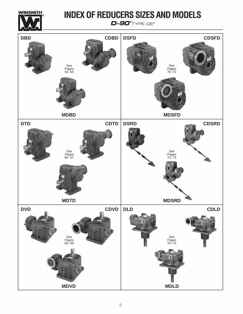
INDEX OF REDUCERS SIZES AND MODELSD—90®
TYPE DE®
DBD CDBD DSFD CDSFD
MDBD MDSFD
DTD CDTD DSRD CDSRD
MDTD MDSRD
DVD CDVD DLD CDLD
MDVD MDLD
5
SeePages64- 65
SeePages66 - 67
SeePages68 - 69
SeePages70- 71
SeePages72- 73
SeePages74 -75

HOW TO SELECT
6
WINSMITH® worm gear speed reducers can be selected in one of two ways:
1. When the INPUT HP and ratio or relative shaft speeds are known, select the unit based on the input HP capacity.2. When the OUTPUT TORQUE and ratio or relative shaft speeds are known, select the unit based on the unit torque capacity.
The following selection procedure and two examples illustrate both conditions.
SELECTION PROCEDURE
1. Select the proper SERVICE FACTOR from the table on Page 80 corresponding to the load classification, durationof service, type of prime mover, and frequency of startingand stopping.
2. Determine the RATIO or OUTPUT RPM required.
Ratio = INPUT RPMOUTPUT RPM
3. Calculate the DESIGN HP or DESIGN TORQUE by multiply-ing the required input HP or required output torque by theservice factor determined in Step One.
4. Determine the proper UNIT SIZE by referring to the ratingcharts on Pages 8-51. For the proper ratio and input RPM,select the minimum unit size where either the rated mechani-cal input HP or output torque is equal to or exceeds thedesign HP or torque from Step 3.
5. For applications involving continuous operation of at leastone hour, refer to the thermal HP or torque capacity for
the same selection and verify that the operating load is nogreater than the unit thermal capacity. If it is not, considerfan-cooling (single reduction), external cooling (heatexchanger) or a larger reducer.
6. Select the reducer model that best suits the applicationspecifications as illustrated on Pages 4-5 and check to see if the size determined in steps 4 and 5 is available inthis model.
7. Check OVERHUNG LOADS on all shafts and/or THRUSTLOAD on the output shaft. Refer to the ratings on Pages 8-51 and explanation in Engineering Section on Page 88.
8. Check dimensions, shaft arrangements, and availableframe sizes for motorized units from the information on specific model dimension pages.
9. Refer to Page 7 for instructions on “HOW TO ORDER.”
EXAMPLE A(Ouput Torque Given)
A pure liquid agitator (uniform load) operates 24 hours perday at approximately 40 RPM and a torque load of 14,000inch pounds. The reducer is to be driven by a 1160 RPMelectric motor.1. Service Factor (from Page 87)—1.25
2. Ratio = 1160 = 29:140
3. Design Torque = 14,000 x 1.25 service factor = 17,500 inch pounds.
4. Unit Selection (from Pages 8-51).A size 951 fan-cooled model is the smallest unit with amechanical output torque rating that is equal to or exceedsthe design torque of 17,500 inch pounds and a thermal outputtorque rating that is equal to or exceeds the operating torqueof 14,000 inch pounds at 1160 RPM input.
EXAMPLE B(Input HP Given)
A customer requires a reducer to direct drive the head shaftof his uniformly loaded belt conveyor at a speed of approxi-mately 30 RPM. The conveyor operates 24 hours per dayand is driven by a 10 HP motor at 1750 RPM.1. Service Factor (from Page 87)—1.25
2. Ratio = 1750 = 58.3:130
3. Design HP= 10 x 1.25 service factor = 12.5 HP. 4. Unit Selection (from Pages 8-51).A size 961 fan-cooled model is the smallest unit with amechanical input HP rating that is equal to or exceeds thedesign HP of 12.5 and a thermal input HP rating that is equalto or exceeds the operating HP of 10 at 1750 RPM input.
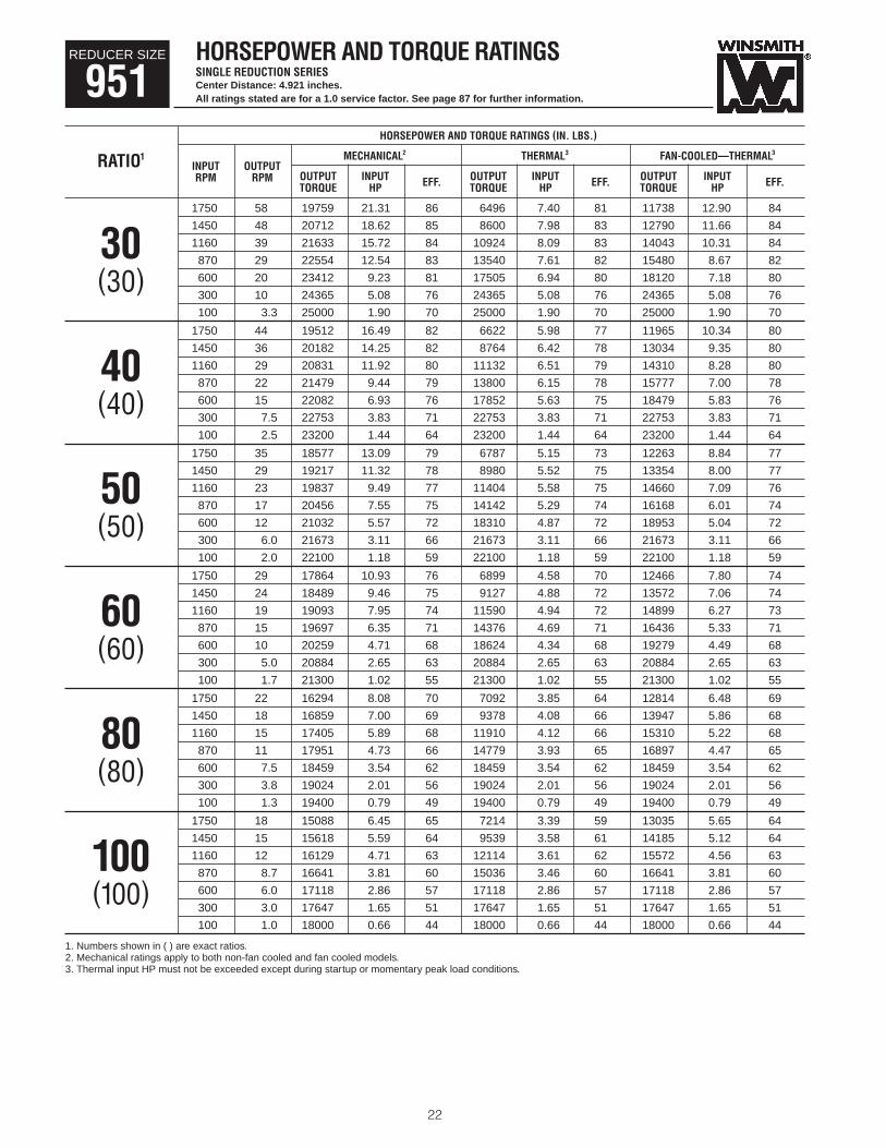
HORSEPOWER AND TORQUE RATINGSSINGLE REDUCTION SERIES
All ratings stated are for a 1.0 service factor. See page 87 for further information.
REDUCER SIZE
951HORSEPOWER AND TORQUE RATINGS
NOMINAL ACTUAL MECHANICAL2 THERMAL3 FAN-COOLED—THERMAL3
RATIO1INPUT OUTPUT OUTPUT OUTPUT INPUT OUTPUT INPUT OUTPUT INPUTRPM RPM RPM TORQUE HP EFF. TORQUE HP EFF. TORQUE HP EFF.
1750 58.30 58.30 19759 21.31 86 6496 7.40 81 11738 12.90 84
1450 48.30 48.30 20712 18.62 85 8600 7.98 83 12790 11.66 84
1160 38.70 38.70 21633 15.72 84 10924 8.09 83 14043 10.31 8430 870 29.00 29.00 22554 12.54 83 13540 7.61 82 15480 8.67 82
600 20.00 20.00 23412 9.23 81 17505 6.94 80 18120 7.18 80(30)300 10.00 10.00 24365 5.08 76 24365 5.08 76 24365 5.08 76
100 3.30 3.30 25000 1.90 70 25000 1.90 70 25000 1.90 70
CENTER DISTANCE 4.921 inches.
HORSEPOWER AND TORQUE RATINGSSINGLE REDUCTION SERIES
All ratings stated are for a 1.0 service factor. See page 87 for further information.
REDUCER SIZE
961 CENTER DISTANCE 5.906 inches.
HORSEPOWER AND TORQUE RATINGS
NOMINAL ACTUAL MECHANICAL2 THERMAL3 FAN-COOLED—THERMAL3
RATIO1INPUT OUTPUT OUTPUT OUTPUT INPUT OUTPUT INPUT OUTPUT INPUTRPM RPM RPM TORQUE HP EFF. TORQUE HP EFF. TORQUE HP EFF.
1750 29.20 29.20 25166 14.85 78 10836 6.83 73 19172 11.49 77
1450 24.20 24.20 26045 12.84 78 14280 7.29 75 21282 10.59 77
1160 19.30 19.30 26895 10.75 77 18117 7.37 75 23762 9.55 7660 870 14.50 14.50 27744 8.55 75 22505 6.99 74 26674 8.23 75
600 10.00 10.00 28535 6.31 72 28535 6.31 72 28535 6.31 72(60)300 5.00 5.00 29414 3.51 66 29414 3.51 66 29414 3.51 66
100 1.70 1.70 30000 1.34 59 30000 1.34 59 30000 1.34 59

HOW TO ORDER
7
EXAMPLE Catalog Description D-90 Series, 3.937" center distance, fan cooled, worm on top, single reduction, doubleextended slow speed shaft, 182TC frame, motorized input, 30:1 ratioCatalog Codes 941, CFDT, LR, 182TC, 30:1 End Unit Part Number 941DDTS23000EK
9 41 D DT S 2 3 00 O EKSERIES
CODE DESC EUPN9 D-90 SERIES 9
CENTER DISTANCE
CODE DESC EUPN41 3.937" 4151 4.921" 5161 5.908" 6171 6.890" 7181 7.874" 8190 9.843" 90
INPUT STYLE
CODE DESC EUPNMF C-Flange w/Quill motor adapter & fan AC C-Flange w/Coupling motor adapter CCF C-Flange w/Coupling motor adapter & fan DF Fan cooled FM C-Flange w/Quill motor adapter M
(blank) Non-Motorized X
BASIC MODEL
CODE DESC EUPND-90 SERIES
DB Worm on bottom DBDT Worm on top DTDV Vertical output shaft DVDL Drop bearing output DLDSF Flange mount hollow output SFDSR Torque arm hollow output SRDSB Foot mt.—wos bottom— SB
hollow outputDST Foot mt.—wos top— ST
hollow output
REDUCTION STAGES
CODE DESC EUPNS Single SD Double DX Helical primary X
SHAFT ARRANGEMENTHorizontal UnitsCODE DESC EUPN
LR Solid out —double ext 2R Solid out—right ext 3L Solid out—left ext 4
Vertical UnitsCODE DESC EUPNRU S.S. right—S.S. up 2RD S.S. right—S.S. down 3LU S.S. left—S.S. up 4LD S.S. left—S.S. down 5
RUD S.S. right—S.S. up & down 6LUD S.S. left—S.S. up & down 7Hollow OutputCODE DESC EUPNDR Driven machine right 3DL Driven machine left 4
DLR Symmetric hollow shaft 5
Double & Triple Reduction2-9 & A-V check with the factory*Viewing Input (Motor end) of high speed shaft.
MOTORFRAME SIZE
CODE/ DESC EUPN56C 1143-145TC 2182-184TC 3213-215TC 4254-256TC 5284-286TC A324-326TC B364-365TC CNon-motorized X
OUTPUT STYLECODE EUPNSolid Output Shaft 00
Hollow Output ShaftCODE DESC EUPN
1-1/2 1.50" Bore 241-3/4 1.75" Bore 28
6-3/16 6.1875" 99
RATIOCODE/ DESC EUPN
5:1 A810:1 B715:1 C120:1 DN25:1 D430:1 EK40:1 FA50:1 FT60:1 GC80:1 HC100:1 HO150:1 J9200:1 LC300:1 MM500:1 N4750:1 P51000:1 QO1500:1 R62000:1 S13000:1 TV4000:1 U85000:1 UE6000:1 UM8000:1 3M10000:1 U5
and others
#—increase EUPN by one for each1/16" increase in bore size
*
( )

HORSEPOWER AND TORQUE RATINGSSINGLE REDUCTION SERIESCenter Distance: 3.937 inches.All ratings stated are for a 1.0 service factor. See page 87 for further information.
8
REDUCER SIZE
941HORSEPOWER AND TORQUE RATINGS (IN. LBS.)
MECHANICAL2 THERMAL3 FAN-COOLED—THERMAL3
RATIO1INPUT OUTPUT
OUTPUT INPUT OUTPUT INPUT OUTPUT INPUTRPM RPMTORQUE HP EFF. TORQUE HP EFF. TORQUE HP EFF.
1750 350 6883 40.07 95 3050 17.97 94 5202 30.38 95
1450 290 7559 36.51 95 3934 19.13 94 5749 27.84 95
1160 232 8212 31.83 95 4895 19.05 94 6362 24.70 95*5*870 174 8865 25.93 94 6007 17.62 94 7089 20.76 94
600 120 9474 19.29 94 7667 15.63 93 8330 16.97 93(5)300 60 10149 10.55 92 10149 10.55 92 10149 10.55 92
100 20 10600 3.80 89 10600 3.80 89 10600 3.80 89
1750 219 8208 30.20 94 4009 14.95 93 6838 25.23 94
1450 181 8498 25.96 94 5147 15.83 93 7522 23.01 94
1160 145 8777 21.54 94 6390 15.73 93 8305 20.39 948 870 109 9057 16.80 93 7852 14.58 93 9057 16.80 93
600 75 9318 12.05 92 9318 12.05 92 9318 12.05 92(8)300 38 9607 6.35 90 9607 6.35 90 9607 6.35 90
100 13 9800 2.24 87 9800 2.24 87 9800 2.24 87
1750 175 9303 27.65 93 4217 12.74 92 7194 21.47 93
1450 145 9921 24.49 93 5412 13.48 92 7910 19.58 93
1160 116 10518 20.87 93 6720 13.40 92 8733 17.36 9310 870 87 11115 16.68 92 8261 12.44 92 9750 14.65 92
600 60 11671 12.23 91 10634 11.16 91 11553 12.11 91(10)300 30 12288 6.61 89 12288 6.61 89 12288 6.61 89
100 10 12700 2.37 85 12700 2.37 85 12700 2.37 85
1750 117 10636 21.79 90 4024 8.48 88 6836 14.20 90
1450 97 11029 18.81 90 5168 8.96 88 7552 12.97 89
1160 77 11410 15.69 89 6416 8.91 88 8339 11.52 8915 870 58 11790 12.32 88 7881 8.28 88 9301 9.75 88
600 40 12144 8.93 86 10119 7.45 86 10994 8.09 86(15)300 20 12538 4.79 83 12538 4.79 83 12538 4.79 83
100 6.7 12800 1.74 78 12800 1.74 78 12800 1.74 78
1750 88 11165 17.63 88 4169 6.82 85 7111 11.36 87
1450 73 11557 15.21 87 5352 7.19 85 7822 10.38 87
1160 58 11936 12.69 87 6645 7.15 85 8636 9.23 8620 870 44 12314 9.98 85 8165 6.67 85 9636 7.84 85
600 30 12667 7.26 83 10495 6.03 83 11402 6.54 83(20)300 15 13059 3.93 79 13059 3.93 79 13059 3.93 79
100 5.0 13320 1.44 74 13320 1.44 74 13320 1.44 74
1750 70 10964 13.97 87 5049 6.64 85 8612 11.06 87
1450 58 11349 12.05 87 6475 6.99 85 9463 10.09 86
1160 46 11721 10.04 86 8047 6.96 85 10458 8.98 8625 870 35 12093 7.90 85 9926 6.51 84 11715 7.66 84
600 24 12439 5.74 83 12439 5.74 83 12439 5.74 83(25)300 12 12824 3.10 79 12824 3.10 79 12824 3.10 79
100 4.0 13080 1.12 74 13080 1.12 74 13080 1.12 74
1. Numbers shown in ( ) are exact ratios.2. Mechanical ratings apply to both non-fan cooled and fan cooled models.3. Thermal input HP must not be exceeded except during startup or momentary peak load conditions.*Available in solid shaft only.

9
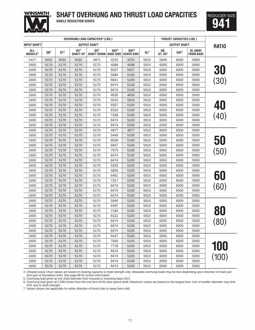
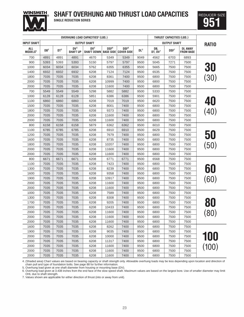
SHAFT OVERHUNG AND THRUST LOAD CAPACITIESSINGLE REDUCTION SERIES
REDUCER SIZE
941OVERHUNG LOAD CAPACITIES4 (LBS.) THRUST CAPACITIES (LBS.)
INPUT SHAFT OUTPUT SHAFT OUTPUT SHAFT
ALL DV 5 DV5 †DSF6 †DSF6 DB, DL AWAYRATIO
MODELS5 DB5 DT5SHAFT UP SHAFT DOWN BASE SIDE COVER SIDE DL5
DT, DV7 DSF7FROM BASE
1600 3045 3045 3045 3008 2685 2685 4597 2739 6000 2726
1600 3209 3209 3209 3170 2836 2836 4877 2849 6000 2834
1600 3462 3462 3462 3419 3029 3029 5267 3063 6000 3047
1600 3859 3859 3859 3812 3297 3297 5843 3441 6000 3424 51600 4431 4431 4431 4377 3701 3701 5910 4023 6000 4005
1600 5170 5170 5170 5170 4688 4688 5910 5401 6000 5000(5)
1600 5170 5170 5170 5170 6639 5100 5910 6000 6000 5000
1600 3395 3395 3395 3354 2944 2944 5093 3199 6000 3265
1600 3702 3702 3702 3656 3156 3156 5510 3527 6000 3595
1600 4083 4083 4083 4033 3414 3414 5910 3942 6000 4013
1600 4600 4600 4600 4544 3814 3814 5910 4511 6000 4584 81600 5170 5170 5170 5170 4384 4384 5910 5301 6000 5000
1600 5170 5170 5170 5170 5544 5100 5910 6000 6000 5000(8)
1600 5170 5170 5170 5170 7995 5100 5910 6000 6000 5000
1600 3555 3555 3555 3512 3064 3064 5363 3462 6000 3436
1600 3841 3841 3841 3794 3261 3261 5783 3748 6000 3720
1600 4208 4208 4208 4156 3547 3547 5910 4126 6000 4098
1600 4718 4718 4718 4660 3964 3964 5910 4668 6000 4638 101600 5170 5170 5170 5170 4544 4544 5910 5506 6000 5000
1600 5170 5170 5170 5170 5803 5100 5910 6000 6000 5000(10)
1600 5170 5170 5170 5170 8429 5100 5910 6000 6000 5000
1065 3929 3929 3929 3881 3386 3386 5910 4161 6000 4112
1319 4283 4283 4283 4230 3678 3678 5910 4555 6000 4505
1600 4725 4725 4725 4667 4040 4040 5910 5050 6000 4998
1600 5170 5170 5170 5170 4528 4528 5910 5801 6000 5000 151600 5170 5170 5170 5170 5195 5100 5910 6000 6000 5000
1600 5170 5170 5170 5170 6785 5100 5910 6000 6000 5000(15)
1600 5170 5170 5170 5170 8474 5100 5910 6000 6000 5000
859 4285 4285 4285 4232 3693 3693 5910 4685 6000 4631
1120 4670 4670 4670 4613 4010 4010 5910 5120 6000 5000
1497 5170 5170 5170 5147 4402 4402 5910 5735 6000 5000
1600 5170 5170 5170 5170 4930 4930 5910 6000 6000 5000 201600 5170 5170 5170 5170 5707 5100 5910 6000 6000 5000
1600 5170 5170 5170 5170 7491 5100 5910 6000 6000 5000(20)
1600 5170 5170 5170 5170 8474 5100 5910 6000 6000 5000
1518 4701 4701 4701 4644 3996 3996 5910 5168 6000 5000
1600 5170 5170 5170 5111 4335 4335 5910 5707 6000 5000
1600 5170 5170 5170 5170 4752 4752 5910 6000 6000 5000
1600 5170 5170 5170 5170 5318 5100 5910 6000 6000 5000 251600 5170 5170 5170 5170 6222 5100 5910 6000 6000 5000
1600 5170 5170 5170 5170 8133 5100 5910 6000 6000 5000(25)
1600 5170 5170 5170 5170 8474 5100 5910 6000 6000 5000
4. (Shaded area) Chart values are based on bearing capacity or shaft strength only. Allowable overhung loads may be less depending upon direction of chain pulland type of foundation bolts. See page 88 for further information.
5. Overhung load given at one shaft diameter from housing or mounting base (DV).6. Overhung load given at 2.938 inches from the end face of the slow speed shaft. Maximum values are based on the largest bore. Use of smaller diameter may limit
OHL due to shaft strength.7. Values shown are applicable for either direction of thrust (into or away from unit).

HORSEPOWER AND TORQUE RATINGSSINGLE REDUCTION SERIESCenter Distance: 3.937 inches.All ratings stated are for a 1.0 service factor. See page 87 for further information.
10
REDUCER SIZE
941HORSEPOWER AND TORQUE RATINGS (IN. LBS.)
MECHANICAL2 THERMAL3 FAN-COOLED—THERMAL3
RATIO1INPUT OUTPUT
OUTPUT INPUT OUTPUT INPUT OUTPUT INPUTRPM RPMTORQUE HP EFF. TORQUE HP EFF. TORQUE HP EFF.
1750 58 10994 11.99 85 4829 5.50 82 8238 9.12 84
1450 48 11327 10.35 84 6194 5.78 82 9053 8.32 83
1160 39 11697 8.65 83 7694 5.75 82 9999 7.42 8330 870 29 12067 6.83 81 9479 5.39 81 11187 6.34 81
600 20 12412 4.98 79 12256 4.92 79 12412 4.98 79(30)300 10 12795 2.72 75 12795 2.72 75 12795 2.72 75
100 3.3 13050 1.00 69 13050 1.00 69 13050 1.00 69
1750 44 10791 9.28 81 4987 4.49 78 8507 7.40 80
1450 36 11156 8.01 80 6396 4.71 78 9348 6.76 80
1160 29 11509 6.70 79 7947 4.69 78 10329 6.04 7940 870 22 11862 5.31 77 9799 4.41 77 11564 5.18 77
600 15 12191 3.90 74 12191 3.90 74 12191 3.90 74(40)300 7.5 12556 2.14 70 12556 2.14 70 12556 2.14 70
100 2.5 12800 .80 63 12800 .80 63 12800 .80 63
1750 35 10310 7.44 77 5056 3.84 74 8624 6.28 76
1450 29 10672 6.43 76 6484 4.02 74 9476 5.74 76
1160 23 11022 5.40 75 8057 4.00 74 10471 5.14 7550 870 17 11371 4.30 73 9937 3.78 73 11371 4.30 73
600 12 11697 3.17 70 11697 3.17 70 11697 3.17 70(50)300 6.0 12059 1.77 65 12059 1.77 65 12059 1.77 65
100 2.0 12300 .67 58 12300 .67 58 12300 .67 58
1750 29 9833 6.18 74 5150 3.42 70 8784 5.56 73
1450 24 10178 5.35 73 6604 3.56 71 9652 5.08 73
1160 19 10511 4.49 72 8208 3.55 71 10511 4.49 7260 870 15 10845 3.59 70 10129 3.36 69 10845 3.59 70
600 10 11155 2.66 67 11155 2.66 67 11155 2.66 67(60)300 5.0 11500 1.49 61 11500 1.49 61 11500 1.49 61
100 1.7 11730 .57 54 11730 .57 54 11730 .57 54
1750 22 8801 4.52 68 5309 2.87 64 8801 4.52 68
1450 18 9110 3.91 67 6809 2.99 65 9110 3.91 67
1160 15 9409 3.29 66 8466 2.98 65 9409 3.29 6680 870 11 9707 2.64 63 9707 2.64 63 9707 2.64 63
600 7.5 9985 1.97 60 9985 1.97 60 9985 1.97 60(80)300 3.8 10294 1.12 55 10294 1.12 55 10294 1.12 55
100 1.3 10500 .43 48 10500 .43 48 10500 .43 48
1750 18 8037 3.58 62 5392 2.53 59 8037 3.58 62
1450 15 8319 3.10 62 6916 2.62 60 8319 3.10 62
1160 12 8592 2.61 61 8592 2.61 60 8592 2.61 61100 870 8.7 8865 2.11 58 8865 2.11 58 8865 2.11 58
600 6.0 9119 1.58 55 9119 1.58 55 9119 1.58 55(100)300 3.0 9402 .91 49 9402 .91 49 9402 .91 49
100 1.0 9590 .36 43 9590 .36 43 9590 .36 43
1. Numbers shown in ( ) are exact ratios.2. Mechanical ratings apply to both non-fan cooled and fan cooled models.3. Thermal input HP must not be exceeded except during startup or momentary peak load conditions.
11
SHAFT OVERHUNG AND THRUST LOAD CAPACITIESSINGLE REDUCTION SERIES
REDUCER SIZE
941OVERHUNG LOAD CAPACITIES4 (LBS.) THRUST CAPACITIES (LBS.)
INPUT SHAFT OUTPUT SHAFT OUTPUT SHAFT
ALL DV 5 DV5 †DSF6 †DSF6 DB, DL AWAYRATIO
MODELS5 DB5 DT5SHAFT UP SHAFT DOWN BASE SIDE COVER SIDE DL5
DT, DV7 DSF7FROM BASE
1417 5032 5032 5032 4971 4232 4232 5910 5649 6000 5000
1600 5170 5170 5170 5170 4588 4588 5910 6000 6000 5000
1600 5170 5170 5170 5170 5027 5027 5910 6000 6000 5000
1600 5170 5170 5170 5170 5684 5100 5910 6000 6000 5000 301600 5170 5170 5170 5170 6641 5100 5910 6000 6000 5000
1600 5170 5170 5170 5170 8474 5100 5910 6000 6000 5000(30)
1600 5170 5170 5170 5170 8474 5100 5910 6000 6000 5000
1600 5170 5170 5170 5170 4630 4630 5910 6000 6000 5000
1600 5170 5170 5170 5170 5016 5016 5910 6000 6000 5000
1600 5170 5170 5170 5170 5557 5100 5910 6000 6000 5000
1600 5170 5170 5170 5170 6310 5100 5910 6000 6000 5000 401600 5170 5170 5170 5170 7358 5100 5910 6000 6000 5000
1600 5170 5170 5170 5170 8474 5100 5910 6000 6000 5000(40)
1600 5170 5170 5170 5170 8474 5100 5910 6000 6000 5000
1600 5170 5170 5170 5170 4977 4977 5910 6000 6000 5000
1600 5170 5170 5170 5170 5449 5100 5910 6000 6000 5000
1600 5170 5170 5170 5170 6039 5100 5910 6000 6000 5000
1600 5170 5170 5170 5170 6847 5100 5910 6000 6000 5000 501600 5170 5170 5170 5170 7970 5100 5910 6000 6000 5000
1600 5170 5170 5170 5170 8474 5100 5910 6000 6000 5000(50)
1600 5170 5170 5170 5170 8474 5100 5910 6000 6000 5000
1600 5170 5170 5170 5170 5334 5100 5910 6000 6000 5000
1600 5170 5170 5170 5170 5835 5100 5910 6000 6000 5000
1600 5170 5170 5170 5170 6461 5100 5910 6000 6000 5000
1600 5170 5170 5170 5170 7317 5100 5910 6000 6000 5000 601600 5170 5170 5170 5170 8474 5100 5910 6000 6000 5000
1600 5170 5170 5170 5170 8474 5100 5910 6000 6000 5000(60)
1600 5170 5170 5170 5170 8474 5100 5910 6000 6000 5000
1600 5170 5170 5170 5170 5946 5100 5910 6000 6000 5000
1600 5170 5170 5170 5170 6497 5100 5910 6000 6000 5000
1600 5170 5170 5170 5170 7184 5100 5910 6000 6000 5000
1600 5170 5170 5170 5170 8121 5100 5910 6000 6000 5000 801600 5170 5170 5170 5170 8474 5100 5910 6000 6000 5000
1600 5170 5170 5170 5170 8474 5100 5910 6000 6000 5000(80)
1600 5170 5170 5170 5170 8474 5100 5910 6000 6000 5000
1600 5170 5170 5170 5170 6447 5100 5910 6000 6000 5000
1600 5170 5170 5170 5170 7040 5100 5910 6000 6000 5000
1600 5170 5170 5170 5170 7778 5100 5910 6000 6000 5000
1600 5170 5170 5170 5170 8474 5100 5910 6000 6000 5000 1001600 5170 5170 5170 5170 8474 5100 5910 6000 6000 5000
1600 5170 5170 5170 5170 8474 5100 5910 6000 6000 5000(100)
1600 5170 5170 5170 5170 8474 5100 5910 6000 6000 5000
4. (Shaded area) Chart values are based on bearing capacity or shaft strength only. Allowable overhung loads may be less depending upon direction of chain pulland type of foundation bolts. See page 88 for further information.
5. Overhung load given at one shaft diameter from housing or mounting base (DV).6. Overhung load given at 2.938 inches from the end face of the slow speed shaft. Maximum values are based on the largest bore. Use of smaller diameter may limit
OHL due to shaft strength.7. Values shown are applicable for either direction of thrust (into or away from unit).

HORSEPOWER AND TORQUE RATINGSDOUBLE REDUCTION SERIES(D) Double Reduction Worm Gear(H) Double Reduction Helical/WormAll ratings stated are for a 1.0 service factor. See page 87 for further information.
12
REDUCER SIZE
941HORSEPOWER AND TORQUE RATINGS (IN. LBS.)
OVERALL MECHANICAL THERMAL3
RATIO2PRIMARY SECONDARY INPUT OUTPUT
RATIO2 RATIO2 RPM RPM HP TORQUE HP TORQUE
1750 69.13 11.33 9217 — —
5 5 1160 45.82 7.74 9378 — —25 (H)(5.06) (5) 600 23.70 4.16 9546 — —
(25.3)100 3.95 0.75 9861 — —
1750 59.03 9.94 9423 — —
6 5 1160 39.13 6.78 9573 — —30 (H)(5.93) (5) 600 20.24 3.64 9736 — —
(29.6)100 3.37 0.65 9977 — —
1750 43.21 7.48 9563 — —
5 8 1160 28.64 5.08 9675 — —40 (H)(5.06) (8) 600 14.81 2.72 9782 — —
(40.5)100 2.47 0.47 9800 — —
1750 34.56 7.75 12194 — —
5 10 1160 22.91 5.32 12434 — —50 (H)(5.06) (10) 600 11.85 2.87 12662 — —
(50.6)100 1.98 0.51 12700 — —
1750 29.52 6.71 12298 — —
6 10 1160 19.56 4.60 12503 — —60 (H)(5.93) (10) 600 10.12 2.47 12698 — —
(59.3)100 1.69 0.44 12700 — —
1750 23.04 5.62 12478 — —
5 15 1160 15.27 3.86 12631 — —75 (H)(5.06) (15) 600 7.90 2.10 12776 — —
(75.9)100 1.32 0.38 12800 — —
1750 19.68 4.87 12544 — —
6 15 1160 13.04 3.34 12675 — —90 (H)(5.93) (15) 600 6.75 1.81 12798 — —
(88.9)100 1.12 0.33 12800 — —
1750 17.50 4.77 12994 — —
5 20 1160 11.60 3.32 13148 — —100 (D)(5) (20) 600 6.00 1.84 13294 — —
(100) 100 1.00 0.35 13320 — —
1750 17.28 4.59 12999 — —
5 20 1160 11.46 3.17 13151 — —100 (H)(5.06) (20) 600 5.93 1.73 13296 — —
(101.3) 100 0.99 0.32 13320 — —
1. Center Distance = Primary/Secondary.2. Numbers shown in ( ) are actual ratios. Worm ratios are exact, helical ratios are rounded and are not exact.3. Ratings provided only if thermally limited. Thermal HP must not be exceeded except during startup or momentary peak conditions.
CENTER DISTANCE (1) 2.625/3.937 (D)CENTER DISTANCE (1) 3.200/3.937 (H)

OVERHUNG LOAD CAPACITIES4 (LBS.) THRUST CAPACITIES (LBS.)
INPUT SHAFT OUTPUT SHAFT OUTPUT SHAFT
ALL DBD5 DVD5 DVD5 †DSFD6 †DSFD6 DBD, DLD AWAYINPUT RATIO
MODELS5 DTD5 SHAFT UP SHAFT DOWN BASE SIDE COVER SIDE DLD5DTD, DVD7 DSFD7
FROM BASERPM
220 5170 5170 5170 4445 4445 5910 6000 6000 5000 1750
318 5170 5170 5170 5043 5043 5910 6000 6000 5000 1160
500 5170 5170 5170 5478 5100 5910 6000 6000 5000 60025 (H)
500 5170 5170 5170 6234 5100 5910 6000 6000 5000 100 (25.3)192 5170 5170 5170 4724 4724 5910 6000 6000 5000 1750
393 5170 5170 5170 5314 5100 5910 6000 6000 5000 1160
500 5170 5170 5170 5837 5100 5910 6000 6000 5000 60030 (H)
500 5170 5170 5170 6639 5100 5910 6000 6000 5000 100 (29.6)500 5170 5170 5170 5274 5100 5910 6000 6000 5000 1750
500 5170 5170 5170 6027 5100 5910 6000 6000 5000 1160
500 5170 5170 5170 6643 5100 5910 6000 6000 5000 60040 (H)
500 5170 5170 5170 7524 5100 5910 6000 6000 5000 100 (40.5)500 5170 5170 5170 5465 5100 5910 6000 6000 5000 1750
500 5170 5170 5170 6337 5100 5910 6000 6000 5000 1160
500 5170 5170 5170 6991 5100 5910 6000 6000 5000 60050 (H)
500 5170 5170 5170 7928 5100 5910 6000 6000 5000 100 (50.6)500 5170 5170 5170 5857 5100 5910 6000 6000 5000 1750
500 5170 5170 5170 6748 5100 5910 6000 6000 5000 1160
500 5170 5170 5170 7437 5100 5910 6000 6000 5000 60060 (H)
500 5170 5170 5170 8429 5100 5910 6000 6000 5000 100 (59.3)500 5170 5170 5170 6398 5100 5910 6000 6000 5000 1750
500 5170 5170 5170 7396 5100 5910 6000 6000 5000 1160
500 5170 5170 5170 8141 5100 5910 6000 6000 5000 60075 (H)
500 5170 5170 5170 8474 5100 5910 6000 6000 5000 100 (75.9)500 5170 5170 5170 6847 5100 5910 6000 6000 5000 1750
500 5170 5170 5170 7865 5100 5910 6000 6000 5000 1160
500 5170 5170 5170 8474 5100 5910 6000 6000 5000 60090 (H)
500 5170 5170 5170 8474 5100 5910 6000 6000 5000 100 (88.9)500 5170 5170 5170 7068 5100 5910 6000 6000 5000 1750
500 5170 5170 5170 8158 5100 5910 6000 6000 5000 1160
500 5170 5170 5170 8474 5100 5910 6000 6000 5000 600100 (D)
500 5170 5170 5170 8474 5100 5910 6000 6000 5000 100 (100)500 5170 5170 5170 8474 5100 5910 6000 6000 5000 1750
500 5170 5170 5170 8474 5100 5910 6000 6000 5000 1160
500 5170 5170 5170 8474 5100 5910 6000 6000 5000 600100 (H)
500 5170 5170 5170 8474 5100 5910 6000 6000 5000 100 (101.3)4. (Shaded area) Chart values are based on bearing capacity or shaft strength only. Allowable overhung loads may be less depending upon direction of chain pull
and type of foundation bolts. See page 88 for further information.5. Overhung load given at one shaft diameter from housing or mounting base (DV).6. Overhung load given at 2.938 inches from the end face of the slow speed shaft. Maximum values are based on the largest bore. Use of smaller diameter may limit
OHL due to shaft strength.7. Values shown are applicable for either direction of thrust (into or away from unit).
13
SHAFT OVERHUNG AND THRUST LOAD CAPACITIESDOUBLE REDUCTION SERIES(D) Double Reduction Worm Gear(H) Double Reduction Helical/Worm
REDUCER SIZE
941

14
HORSEPOWER AND TORQUE RATINGSDOUBLE REDUCTION SERIES(D) Double Reduction Worm Gear(H) Double Reduction Helical/WormAll ratings stated are for a 1.0 service factor. See page 87 for further information.
REDUCER SIZE
941HORSEPOWER AND TORQUE RATINGS (IN. LBS.)
OVERALL MECHANICAL THERMAL3
RATIO2PRIMARY SECONDARY INPUT OUTPUT
RATIO2 RATIO2 RPM RPM HP TORQUE HP TORQUE
1750 14.76 3.99 13065 — —
6 20 1160 9.78 2.75 13195 — —120 (H)(5.93) (20) 600 5.06 1.50 13318 — —
(118.6) 100 0.84 0.28 13320 — —
1750 11.67 3.32 12731 — —
5 30 1160 7.73 2.31 12882 — —150 (D)(5) (30) 600 4.00 1.29 13024 — —
(150) 100 0.67 0.25 13050 — —
1750 11.52 3.13 12736 — —
5 30 1160 7.64 2.16 12885 — —150 (H)(5.06) (30) 600 3.95 1.18 13026 — —
(151.9) 100 0.66 0.22 13050 — —
1750 9.84 2.71 12801 — —
6 30 1160 6.52 1.87 12928 — —180 (H)(5.93) (30) 600 3.37 1.02 13048 — —
(177.9) 100 0.56 0.19 13050 — —
1750 8.75 2.62 12496 — —
5 40 1160 5.80 1.84 12639 — —200 (D)(5) (40) 600 3.00 1.03 12776 — —
(200) 100 0.50 0.20 12800 — —
1750 8.64 2.50 12501 — —
5 40 1160 5.73 1.74 12643 — —200 (H)(5.06) (40) 600 2.96 0.96 12777 — —
(202.5)100 0.49 0.18 12800 — —
1750 6.91 2.06 12004 — —
5 50 1160 4.58 1.44 12144 — —250 (H)(5.06) (50) 600 2.37 0.80 12278 — —
(253.2)100 0.40 0.15 12300 — —
1750 5.83 1.83 12954 — —
10 30 1160 3.87 1.27 13030 — —300 (D)(10) (30) 600 2.00 0.69 13050 — —
(300) 100 0.33 0.13 13050 — —
1750 5.90 1.79 12065 — —
6 50 1160 3.91 1.25 12185 — —300 (H)(5.93) (50) 600 2.02 0.70 12299 — —
(296.5)100 0.34 0.13 12300 — —
1. Center Distance = Primary/Secondary.2. Numbers shown in ( ) are actual ratios. Worm ratios are exact, helical ratios are rounded and are not exact.3. Ratings provided only if thermally limited. Thermal HP must not be exceeded except during startup or momentary peak conditions.
CENTER DISTANCE (1) 2.625/3.937 (D)CENTER DISTANCE (1) 3.200/3.937 (H)

15
OVERHUNG LOAD CAPACITIES4 (LBS.) THRUST CAPACITIES (LBS.)
INPUT SHAFT OUTPUT SHAFT OUTPUT SHAFT
ALL DBD5 DVD5 DVD5 †DSFD6 †DSFD6 DBD, DLD AWAYINPUT RATIO
MODELS5 DTD5 SHAFT UP SHAFT DOWN BASE SIDE COVER SIDE DLD5DTD, DVD7 DSFD7
FROM BASERPM
500 5170 5170 5170 8474 4445 5910 6000 6000 5000 1750
500 5170 5170 5170 8474 5043 5910 6000 6000 5000 1160
500 5170 5170 5170 8474 5100 5910 6000 6000 5000 600120 (H)
500 5170 5170 5170 8474 5100 5910 6000 6000 5000 100 (118.6)500 5170 5170 5170 8184 5100 5910 6000 6000 5000 1750
500 5170 5170 5170 8474 5100 5910 6000 6000 5000 1160
500 5170 5170 5170 8474 5100 5910 6000 6000 5000 600150 (D)
500 5170 5170 5170 8474 5100 5910 6000 6000 5000 100 (150)500 5170 5170 5170 8474 5100 5910 6000 6000 5000 1750
500 5170 5170 5170 8474 5100 5910 6000 6000 5000 1160
500 5170 5170 5170 8474 5100 5910 6000 6000 5000 600150 (H)
500 5170 5170 5170 8474 5100 5910 6000 6000 5000 100 (151.9)500 5170 5170 5170 8474 5100 5910 6000 6000 5000 1750
500 5170 5170 5170 8474 5100 5910 6000 6000 5000 1160
500 5170 5170 5170 8474 5100 5910 6000 6000 5000 600180 (H)
500 5170 5170 5170 8474 5100 5910 6000 6000 5000 100 (177.9)500 5170 5170 5170 8474 5100 5910 6000 6000 5000 1750
500 5170 5170 5170 8474 5100 5910 6000 6000 5000 1160
500 5170 5170 5170 8474 5100 5910 6000 6000 5000 600200 (D)
500 5170 5170 5170 8474 5100 5910 6000 6000 5000 100 (200)500 5170 5170 5170 8474 5100 5910 6000 6000 5000 1750
500 5170 5170 5170 8474 5100 5910 6000 6000 5000 1160
500 5170 5170 5170 8474 5100 5910 6000 6000 5000 600200 (H)
500 5170 5170 5170 8474 5100 5910 6000 6000 5000 100 (202.5)500 5170 5170 5170 8474 5100 5910 6000 6000 5000 1750
500 5170 5170 5170 8474 5100 5910 6000 6000 5000 1160
500 5170 5170 5170 8474 5100 5910 6000 6000 5000 600250 (H)
500 5170 5170 5170 8474 5100 5910 6000 6000 5000 100 (253.2)250 5170 5170 5170 8474 5100 5910 6000 6000 5000 1750
250 5170 5170 5170 8474 5100 5910 6000 6000 5000 1160
250 5170 5170 5170 8474 5100 5910 6000 6000 5000 600300 (D)
250 5170 5170 5170 8474 5100 5910 6000 6000 5000 100(300)
500 5170 5170 5170 8474 5100 5910 6000 6000 5000 1750
500 5170 5170 5170 8474 5100 5910 6000 6000 5000 1160
500 5170 5170 5170 8474 5100 5910 6000 6000 5000 600300 (H)
500 5170 5170 5170 8474 5100 5910 6000 6000 5000 100 (296.5)4. (Shaded area) Chart values are based on bearing capacity or shaft strength only. Allowable overhung loads may be less depending upon direction of chain pull
and type of foundation bolts. See page 88 for further information.5. Overhung load given at one shaft diameter from housing or mounting base (DV).6. Overhung load given at 2.938 inches from the end face of the slow speed shaft. Maximum values are based on the largest bore. Use of smaller diameter may limit
OHL due to shaft strength.7. Values shown are applicable for either direction of thrust (into or away from unit).
SHAFT OVERHUNG AND THRUST LOAD CAPACITIESDOUBLE REDUCTION SERIES(D) Double Reduction Worm Gear(H) Double Reduction Helical/Worm
REDUCER SIZE
941

16
HORSEPOWER AND TORQUE RATINGSDOUBLE REDUCTION SERIES(D) Double Reduction Worm Gear(H) Double Reduction Helical/WormAll ratings stated are for a 1.0 service factor. See page 87 for further information.
REDUCER SIZE
941HORSEPOWER AND TORQUE RATINGS (IN. LBS.)
OVERALL MECHANICAL THERMAL3
RATIO2PRIMARY SECONDARY INPUT OUTPUT
RATIO2 RATIO2 RPM RPM HP TORQUE HP TORQUE
1750 4.92 1.52 11506 — —
6 60 1160 3.26 1.06 11620 — —360 (H)(5.93) (60) 600 1.69 0.59 11729 — —
(355.7) 100 0.28 0.12 11730 — —
1750 3.50 1.21 13320 — —
25 20 1160 2.32 0.83 13320 — —500 (D)(25) (20) 600 1.20 0.45 13320 — —
(500) 100 0.20 0.09 13320 — —
1750 2.33 0.86 13050 — —
25 30 1160 1.55 0.59 13050 — —750 (D)(25) (30) 600 0.80 0.32 13050 — —
(750) 100 0.13 0.06 13050 — —
1750 1.75 0.70 12800 — —
25 40 1160 1.16 0.48 12800 — —1000 (D)(25) (40) 600 0.60 0.26 12800 — —
(1000) 100 0.10 0.05 12800 — —
1750 1.17 0.52 13050 — —
50 30 1160 0.77 0.35 13050 — —1500 (D)(50) (30) 600 0.40 0.20 13050 — —
(1500)100 0.07 0.04 13050 — —
1750 0.88 0.43 12800 — —
50 40 1160 0.58 0.29 12800 — —2000 (D)(50) (40) 600 0.30 0.16 12800 — —
(2000)100 0.05 0.03 12800 — —
1750 0.58 0.33 12300 — —
60 50 1160 0.39 0.23 12300 — —3000 (D)(60) (50) 600 0.20 0.12 12300 — —
(3000)100 0.03 0.02 12300 — —
1750 0.44 0.28 12300 — —
80 50 1160 0.29 0.19 12300 — —4000 (D)(80) (50) 600 0.15 0.10 12300 — —
(4000)100 0.03 0.02 12300 — —
1750 0.35 0.24 12300 — —
100 50 1160 0.23 0.17 12300 — —5000 (D)(100) (50) 600 0.12 0.09 12300 — —
(5000)100 0.02 0.02 12300 — —
1. Center Distance = Primary/Secondary.2. Numbers shown in ( ) are actual ratios. Worm ratios are exact, helical ratios are rounded and are not exact.3. Ratings provided only if thermally limited. Thermal HP must not be exceeded except during startup or momentary peak conditions.
CENTER DISTANCE (1) 2.625/3.937 (D)CENTER DISTANCE (1) 3.200/3.937 (H)

17
OVERHUNG LOAD CAPACITIES4 (LBS.) THRUST CAPACITIES (LBS.)
INPUT SHAFT OUTPUT SHAFT OUTPUT SHAFT
ALL DBD5 DVD5 DVD5 †DSFD6 †DSFD6 DBD, DLD AWAYINPUT RATIO
MODELS5 DTD5 SHAFT UP SHAFT DOWN BASE SIDE COVER SIDE DLD5DTD, DVD7 DSFD7
FROM BASERPM
500 5170 5170 5170 8474 5100 5910 6000 6000 5000 1750
500 5170 5170 5170 8474 5100 5910 6000 6000 5000 1160
500 5170 5170 5170 8474 5100 5910 6000 6000 5000 600360 (H)
500 5170 5170 5170 8474 5100 5910 6000 6000 5000 100 (355.7)275 5170 5170 5170 8474 5100 5910 6000 6000 5000 1750
275 5170 5170 5170 8474 5100 5910 6000 6000 5000 1160
275 5170 5170 5170 8474 5100 5910 6000 6000 5000 600500 (D)
275 5170 5170 5170 8474 5100 5910 6000 6000 5000 100 (500)275 5170 5170 5170 8474 5100 5910 6000 6000 5000 1750
275 5170 5170 5170 8474 5100 5910 6000 6000 5000 1160
275 5170 5170 5170 8474 5100 5910 6000 6000 5000 600750 (D)
275 5170 5170 5170 8474 5100 5910 6000 6000 5000 100 (750)275 5170 5170 5170 8474 5100 5910 6000 6000 5000 1750
275 5170 5170 5170 8474 5100 5910 6000 6000 5000 1160
275 5170 5170 5170 8474 5100 5910 6000 6000 5000 6001000 (D)
275 5170 5170 5170 8474 5100 5910 6000 6000 5000 100 (1000)285 5170 5170 5170 8474 5100 5910 6000 6000 5000 1750
285 5170 5170 5170 8474 5100 5910 6000 6000 5000 1160
285 5170 5170 5170 8474 5100 5910 6000 6000 5000 6001500 (D)
285 5170 5170 5170 8474 5100 5910 6000 6000 5000 100 (1500)285 5170 5170 5170 8474 5100 5910 6000 6000 5000 1750
285 5170 5170 5170 8474 5100 5910 6000 6000 5000 1160
285 5170 5170 5170 8474 5100 5910 6000 6000 5000 6002000 (D)
285 5170 5170 5170 8474 5100 5910 6000 6000 5000 100 (2000)270 5170 5170 5170 8474 5100 5910 6000 6000 5000 1750
270 5170 5170 5170 8474 5100 5910 6000 6000 5000 1160
270 5170 5170 5170 8474 5100 5910 6000 6000 5000 6003000 (D)
270 5170 5170 5170 8474 5100 5910 6000 6000 5000 100 (3000)270 5170 5170 5170 8474 5100 5910 6000 6000 5000 1750
270 5170 5170 5170 8474 5100 5910 6000 6000 5000 1160
270 5170 5170 5170 8474 5100 5910 6000 6000 5000 6004000 (D)
270 5170 5170 5170 8474 5100 5910 6000 6000 5000 100(4000)
270 5170 5170 5170 8474 5100 5910 6000 6000 5000 1750
270 5170 5170 5170 8474 5100 5910 6000 6000 5000 1160
270 5170 5170 5170 8474 5100 5910 6000 6000 5000 6005000 (D)
270 5170 5170 5170 8474 5100 5910 6000 6000 5000 100(5000)
4. (Shaded area) Chart values are based on bearing capacity or shaft strength only. Allowable overhung loads may be less depending upon direction of chain pulland type of foundation bolts. See page 88 for further information.
5. Overhung load given at one shaft diameter from housing or mounting base (DV).6. Overhung load given at 2.938 inches from the end face of the slow speed shaft. Maximum values are based on the largest bore. Use of smaller diameter may limit
OHL due to shaft strength.7. Values shown are applicable for either direction of thrust (into or away from unit).
SHAFT OVERHUNG AND THRUST LOAD CAPACITIESDOUBLE REDUCTION SERIES(D) Double Reduction Worm Gear(H) Double Reduction Helical/Worm
REDUCER SIZE
941

18
HORSEPOWER AND TORQUE RATINGSDOUBLE REDUCTION SERIES(D) Double Reduction Worm Gear(H) Double Reduction Helical/WormAll ratings stated are for a 1.0 service factor. See page 87 for further information.
REDUCER SIZE
941HORSEPOWER AND TORQUE RATINGS (IN. LBS.)
OVERALL MECHANICAL THERMAL3
RATIO2PRIMARY SECONDARY INPUT OUTPUT
RATIO2 RATIO2 RPM RPM HP TORQUE HP TORQUE
1750 0.29 0.22 11730 — —
100 60 1160 0.19 0.15 11730 — —6000 (D)4
(100) (60) 600 0.10 0.08 11730 — —(6000) 100 0.02 0.01 11730 — —
1750 0.22 0.18 10500 — —
100 80 1160 0.15 0.12 10500 — —8000 (D)4
(100) (80) 600 0.08 0.06 10500 — —(8000) 100 0.01 0.01 10500 — —
1750 0.18 0.16 9590 — —
100 100 1160 0.12 0.11 9590 — —10000 (D)4
(100) (100) 600 0.06 0.06 9590 — —(10000) 100 0.01 0.01 9590 — —
1. Center Distance = Primary/Secondary.2. Numbers shown in ( ) are actual ratios. Worm ratios are exact, helical ratios are rounded and are not exact.3. Ratings provided only if thermally limited. Thermal HP must not be exceeded except during startup or momentary peak conditions.4. Triple reduction models with higher torque capacities are available, check with factory.
CENTER DISTANCE (1) 2.625/3.937 (D)CENTER DISTANCE (1) 3.200/3.937 (H)
19
OVERHUNG LOAD CAPACITIES5 (LBS.) THRUST CAPACITIES (LBS.)
INPUT SHAFT OUTPUT SHAFT OUTPUT SHAFT
ALL DBD6 DVD6 DVD6 †DSFD7 †DSFD7 DBD, DLD AWAYINPUT RATIO
MODELS5 DTD5 SHAFT UP SHAFT DOWN BASE SIDE COVER SIDE DLD6DTD, DVD8 DSFD8
FROM BASERPM
270 5170 5170 5170 8474 5100 5910 6000 6000 5000 1750
270 5170 5170 5170 8474 5100 5910 6000 6000 5000 1160
270 5170 5170 5170 8474 5100 5910 6000 6000 5000 6006000 (D)4
270 5170 5170 5170 8474 5100 5910 6000 6000 5000 100 (6000)270 5170 5170 5170 8474 5100 5910 6000 6000 5000 1750
270 5170 5170 5170 8474 5100 5910 6000 6000 5000 1160
270 5170 5170 5170 8474 5100 5910 6000 6000 5000 6008000 (D)4
270 5170 5170 5170 8474 5100 5910 6000 6000 5000 100 (8000)270 5170 5170 5170 8474 5100 5910 6000 6000 5000 1750
270 5170 5170 5170 8474 5100 5910 6000 6000 5000 1160
270 5170 5170 5170 8474 5100 5910 6000 6000 5000 60010000(D)4
270 5170 5170 5170 8474 5100 5910 6000 6000 5000 100(10000)
5. (Shaded area) Chart values are based on bearing capacity or shaft strength only. Allowable overhung loads may be less depending upon direction of chain pulland type of foundation bolts. See page 88 for further information.
6. Overhung load given at one shaft diameter from housing or mounting base (DV).7. Overhung load given at 2.938 inches from the end face of the slow speed shaft. Maximum values are based on the largest bore. Use of smaller diameter may limit
OHL due to shaft strength.8. Values shown are applicable for either direction of thrust (into or away from unit).
SHAFT OVERHUNG AND THRUST LOAD CAPACITIESDOUBLE REDUCTION SERIES(D) Double Reduction Worm Gear(H) Double Reduction Helical/Worm
REDUCER SIZE
941

HORSEPOWER AND TORQUE RATINGSSINGLE REDUCTION SERIES
All ratings stated are for a 1.0 service factor. See page 87 for further information.
20
REDUCER SIZE
951HORSEPOWER AND TORQUE RATINGS (IN. LBS.)
MECHANICAL2 THERMAL3 FAN-COOLED—THERMAL3
RATIO1INPUT OUTPUT
OUTPUT INPUT OUTPUT INPUT OUTPUT INPUTRPM RPMTORQUE HP EFF. TORQUE HP EFF. TORQUE HP EFF.
1750 350 12165 70.59 96 3987 23.52 94 7204 42.04 95
1450 290 13753 66.18 96 5339 25.95 95 7940 38.39 95
1160 232 15288 59.01 95 6838 26.55 95 8790 34.05 955 870 174 16824 48.97 95 8496 24.84 94 9713 28.37 95
600 120 18253 36.97 94 10902 22.14 94 11285 22.91 94(5)300 60 19841 20.50 92 16868 17.44 92 16868 17.44 92
100 20 20900 7.46 89 20900 7.46 89 20900 7.46 89
1750 219 13100 48.31 94 4300 16.25 92 7719 28.70 93
1450 181 14900 45.58 94 5814 18.04 93 8707 26.81 93
1160 145 16640 40.87 94 7478 18.53 93 9822 24.24 938 870 109 18380 34.11 93 9307 17.38 92 11038 20.57 93
600 75 20000 25.90 92 11989 15.59 92 13047 16.95 92(8)300 38 21800 14.50 90 18750 12.48 89 18750 12.48 89
100 13 23000 5.33 86 23000 5.33 86 23000 5.33 86
1750 175 16721 49.59 94 5205 15.84 91 9406 28.15 93
1450 145 18226 44.89 93 6921 17.31 92 10292 25.53 93
1160 116 19681 38.95 93 8813 17.60 92 11329 22.55 9210 870 87 21136 31.65 92 10917 16.45 92 12482 18.78 92
600 60 22491 23.54 91 14040 14.75 91 14534 15.26 91(10)300 30 23996 12.92 88 22050 11.88 88 22050 11.88 88
100 10 25000 4.71 84 25000 4.71 84 25000 4.71 84
1750 117 18982 38.66 91 5188 10.99 87 9347 19.38 90
1450 97 20076 34.02 91 6901 11.97 88 10262 17.59 90
1160 77 21134 28.85 90 8789 12.17 89 11298 15.56 8915 870 58 22192 23.01 89 10889 11.40 88 12449 13.01 88
600 40 23176 16.90 87 14000 10.27 87 14492 10.62 87(15)300 20 24271 9.22 84 21962 8.35 83 21962 8.35 83
100 6.7 25000 3.39 78 25000 3.39 78 25000 3.39 78
1750 88 20108 31.48 89 5414 8.90 85 9782 15.61 87
1450 73 20998 27.39 88 7194 9.66 86 10698 14.16 87
1160 58 21857 23.01 87 9156 9.81 86 11770 12.53 8720 870 44 22717 18.23 86 11342 9.21 85 12967 10.50 85
600 30 23518 13.33 84 14592 8.33 83 15105 8.62 83(20)300 15 24407 7.28 80 22957 6.85 80 22957 6.85 80
100 5.0 25000 2.69 74 25000 2.69 74 25000 2.69 74
1750 70 19798 24.95 88 6163 8.17 84 11062 14.20 87
1450 58 20744 21.77 88 8268 8.93 85 12383 13.17 87
1160 46 21658 18.34 87 10585 9.11 86 13901 11.88 8625 870 35 22572 14.57 86 13174 8.60 85 15624 10.15 85
600 24 23424 10.68 84 17102 7.83 83 18611 8.51 83(25)300 12 24369 5.82 80 24369 5.82 80 24369 5.82 80
100 4.0 25000 2.14 74 25000 2.14 74 25000 2.14 74
1. Numbers shown in ( ) are exact ratios.2. Mechanical ratings apply to both non-fan cooled and fan cooled models.3. Thermal input HP must not be exceeded except during startup or momentary peak load conditions.
Center Distance: 4.921 inches.

21
SHAFT OVERHUNG AND THRUST LOAD CAPACITIESSINGLE REDUCTION SERIES
REDUCER SIZE
951OVERHUNG LOAD CAPACITIES4 (LBS.) THRUST CAPACITIES (LBS.)
INPUT SHAFT OUTPUT SHAFT OUTPUT SHAFT
ALL DV 5 DV5 †DSF6 †DSF6 DB, DL AWAYRATIO
MODELS5 DB5 DT5SHAFT UP SHAFT DOWN BASE SIDE COVER SIDE DL5
DT, DV7 DSF7FROM BASE
700 2934 2934 2934 2801 3430 3430 4485 1822 3434 3438
800 3027 3027 3027 2891 3579 3579 4303 1769 3489 3487
900 3181 3181 3181 3037 3787 3787 4285 1778 3624 3617
1000 3516 3516 3516 3357 4096 4096 4727 1961 3883 3929 51300 4052 4052 4052 3869 4526 4526 5708 2348 4304 4573
2000 5276 5276 5276 5038 5784 5784 8385 3379 5768 6125(5)
2000 7035 7035 7035 6208 8245 7400 9500 6034 7500 7500
700 3385 3385 3385 3232 3904 3904 6514 2602 4374 4345
800 3560 3560 3560 3399 4081 4081 6697 2668 4502 4492
900 3820 3820 3820 3647 4322 4322 7056 2819 4715 4799
1050 4225 4225 4225 4034 4691 4691 7781 3109 5088 5300 81300 4845 4845 4845 4626 5349 5349 9072 3613 5841 6091
2000 6451 6451 6451 6160 6781 6781 9500 5065 7500 7500(8)
2000 7035 7035 7035 6208 9855 7400 9500 6800 7500 7500
700 3351 3351 3351 3199 3891 3891 6204 2485 4281 4265
800 3586 3586 3586 3424 4111 4111 6579 2639 4492 4555
900 3909 3909 3909 3733 4391 4391 7187 2882 4783 4965
1100 4386 4386 4386 4188 4902 4902 8182 3271 5369 5579 101400 5087 5087 5087 4857 5632 5632 9500 3880 6239 6493
2000 6947 6947 6947 6208 7177 7177 9500 5614 7500 7500(10)
2000 7035 7035 7035 6208 10600 7400 9500 6800 7500 7500
700 3732 3732 3732 3563 4216 4216 7439 3154 4979 5100
800 4055 4055 4055 3872 4567 4567 8029 3441 5403 5539
900 4474 4474 4474 4272 5011 5011 8760 3821 5949 6106
1200 5064 5064 5064 4835 5624 5624 9500 4365 6710 6901 151600 6067 6067 6067 5793 6476 6476 9500 5319 7500 7500
2000 7035 7035 7035 6208 8457 7400 9500 6800 7500 7500(15)
2000 7035 7035 7035 6208 11600 7400 9500 6800 7500 7500
700 4095 4095 4095 3910 4603 4603 8028 3655 5616 5743
800 4472 4472 4472 4270 5001 5001 8677 4009 6117 6263
900 4952 4952 4952 4729 5500 5500 9475 4464 6747 6920
1200 5742 5742 5742 5483 6181 6181 9500 5222 7500 7500 201600 6861 6861 6861 6208 7112 7112 9500 6303 7500 7500
2000 7035 7035 7035 6208 9439 7400 9500 6800 7500 7500(20)
2000 7035 7035 7035 6208 11600 7400 9500 6800 7500 7500
700 4584 4584 4584 4377 5037 5037 8607 4137 6183 6365
900 4988 4988 4988 4763 5461 5461 9295 4517 6716 6919
1000 5595 5595 5595 5343 5991 5991 9500 5097 7386 7500
1400 6441 6441 6441 6150 6713 6713 9500 5909 7500 7500 251800 7035 7035 7035 6208 7811 7400 9500 6800 7500 7500
2000 7035 7035 7035 6208 10303 7400 9500 6800 7500 7500(25)
2000 7035 7035 7035 6208 11600 7400 9500 6800 7500 7500
4. (Shaded area) Chart values are based on bearing capacity or shaft strength only. Allowable overhung loads may be less depending upon location and direction ofchain pull and type of foundation bolts. See page 88 for further information.
5. Overhung load given at one shaft diameter from housing or mounting base (DV).6. Overhung load given at 3.438 inches from the end face of the slow speed shaft. Maximum values are based on the largest bore. Use of smaller diameter may limit
OHL due to shaft strength.7. Values shown are applicable for either direction of thrust (into or away from unit).
HORSEPOWER AND TORQUE RATINGSSINGLE REDUCTION SERIES
All ratings stated are for a 1.0 service factor. See page 87 for further information.
22
REDUCER SIZE
951HORSEPOWER AND TORQUE RATINGS (IN. LBS.)
MECHANICAL2 THERMAL3 FAN-COOLED—THERMAL3
RATIO1INPUT OUTPUT
OUTPUT INPUT OUTPUT INPUT OUTPUT INPUTRPM RPMTORQUE HP EFF. TORQUE HP EFF. TORQUE HP EFF.
1750 58 19759 21.31 86 6496 7.40 81 11738 12.90 84
1450 48 20712 18.62 85 8600 7.98 83 12790 11.66 84
1160 39 21633 15.72 84 10924 8.09 83 14043 10.31 8430 870 29 22554 12.54 83 13540 7.61 82 15480 8.67 82
600 20 23412 9.23 81 17505 6.94 80 18120 7.18 80(30)300 10 24365 5.08 76 24365 5.08 76 24365 5.08 76
100 3.3 25000 1.90 70 25000 1.90 70 25000 1.90 70
1750 44 19512 16.49 82 6622 5.98 77 11965 10.34 80
1450 36 20182 14.25 82 8764 6.42 78 13034 9.35 80
1160 29 20831 11.92 80 11132 6.51 79 14310 8.28 8040 870 22 21479 9.44 79 13800 6.15 78 15777 7.00 78
600 15 22082 6.93 76 17852 5.63 75 18479 5.83 76(40)300 7.5 22753 3.83 71 22753 3.83 71 22753 3.83 71
100 2.5 23200 1.44 64 23200 1.44 64 23200 1.44 64
1750 35 18577 13.09 79 6787 5.15 73 12263 8.84 77
1450 29 19217 11.32 78 8980 5.52 75 13354 8.00 77
1160 23 19837 9.49 77 11404 5.58 75 14660 7.09 7650 870 17 20456 7.55 75 14142 5.29 74 16168 6.01 74
600 12 21032 5.57 72 18310 4.87 72 18953 5.04 72(50)300 6.0 21673 3.11 66 21673 3.11 66 21673 3.11 66
100 2.0 22100 1.18 59 22100 1.18 59 22100 1.18 59
1750 29 17864 10.93 76 6899 4.58 70 12466 7.80 74
1450 24 18489 9.46 75 9127 4.88 72 13572 7.06 74
1160 19 19093 7.95 74 11590 4.94 72 14899 6.27 7360 870 15 19697 6.35 71 14376 4.69 71 16436 5.33 71
600 10 20259 4.71 68 18624 4.34 68 19279 4.49 68(60)300 5.0 20884 2.65 63 20884 2.65 63 20884 2.65 63
100 1.7 21300 1.02 55 21300 1.02 55 21300 1.02 55
1750 22 16294 8.08 70 7092 3.85 64 12814 6.48 69
1450 18 16859 7.00 69 9378 4.08 66 13947 5.86 68
1160 15 17405 5.89 68 11910 4.12 66 15310 5.22 6880 870 11 17951 4.73 66 14779 3.93 65 16897 4.47 65
600 7.5 18459 3.54 62 18459 3.54 62 18459 3.54 62(80)300 3.8 19024 2.01 56 19024 2.01 56 19024 2.01 56
100 1.3 19400 0.79 49 19400 0.79 49 19400 0.79 49
1750 18 15088 6.45 65 7214 3.39 59 13035 5.65 64
1450 15 15618 5.59 64 9539 3.58 61 14185 5.12 64
1160 12 16129 4.71 63 12114 3.61 62 15572 4.56 63100 870 8.7 16641 3.81 60 15036 3.46 60 16641 3.81 60
600 6.0 17118 2.86 57 17118 2.86 57 17118 2.86 57(100)300 3.0 17647 1.65 51 17647 1.65 51 17647 1.65 51
100 1.0 18000 0.66 44 18000 0.66 44 18000 0.66 44
1. Numbers shown in ( ) are exact ratios.2. Mechanical ratings apply to both non-fan cooled and fan cooled models.3. Thermal input HP must not be exceeded except during startup or momentary peak load conditions.
Center Distance: 4.921 inches.
OVERHUNG LOAD CAPACITIES4 (LBS.) THRUST CAPACITIES (LBS.)
INPUT SHAFT OUTPUT SHAFT OUTPUT SHAFT
ALL DV 5 DV5 †DSF6 †DSF6 DB, DL AWAYRATIO
MODELS5 DB5 DT5SHAFT UP SHAFT DOWN BASE SIDE COVER SIDE DL5
DT, DV7 DSF7FROM BASE
700 4891 4891 4891 4670 5349 5349 9049 4562 6703 6893
900 5393 5393 5393 5150 5797 5797 9500 5045 7271 7500
1000 6034 6034 6034 5762 6355 6355 9500 5665 7500 7500
1400 6932 6932 6932 6208 7124 7124 9500 6535 7500 7500 301800 7035 7035 7035 6208 8361 7400 9500 6800 7500 7500
2000 7035 7035 7035 6208 10999 7400 9500 6800 7500 7500(30)
2000 7035 7035 7035 6208 11600 7400 9500 6800 7500 7500
700 5549 5549 5549 5298 5882 5882 9500 5333 7500 7500
1000 6128 6128 6128 5851 6386 6386 9500 5901 7500 7500
1100 6860 6860 6860 6208 7019 7019 9500 6620 7500 7500
1500 7035 7035 7035 6208 8001 7400 9500 6800 7500 7500 401800 7035 7035 7035 6208 9373 7400 9500 6800 7500 7500
2000 7035 7035 7035 6208 11600 7400 9500 6800 7500 7500(40)
2000 7035 7035 7035 6208 11600 7400 9500 6800 7500 7500
800 6158 6158 6158 5879 6362 6362 9500 6010 7500 7500
1100 6785 6785 6785 6208 6910 6910 9500 6629 7500 7500
1200 7035 7035 7035 6208 7679 7400 9500 6800 7500 7500
1600 7035 7035 7035 6208 8735 7400 9500 6800 7500 7500 501800 7035 7035 7035 6208 10207 7400 9500 6800 7500 7500
2000 7035 7035 7035 6208 11600 7400 9500 6800 7500 7500(50)
2000 7035 7035 7035 6208 11600 7400 9500 6800 7500 7500
800 6671 6671 6671 6208 6771 6771 9500 6568 7500 7500
1100 7035 7035 7035 6208 7423 7400 9500 6800 7500 7500
1300 7035 7035 7035 6208 8239 7400 9500 6800 7500 7500
1600 7035 7035 7035 6208 9358 7400 9500 6800 7500 7500 601900 7035 7035 7035 6208 10917 7400 9500 6800 7500 7500
2000 7035 7035 7035 6208 11600 7400 9500 6800 7500 7500(60)
2000 7035 7035 7035 6208 11600 7400 9500 6800 7500 7500
1000 7035 7035 7035 6208 7589 7400 9500 6800 7500 7500
1300 7035 7035 7035 6208 8308 7400 9500 6800 7500 7500
1700 7035 7035 7035 6208 9205 7400 9500 6800 7500 7500
2000 7035 7035 7035 6208 10433 7400 9500 6800 7500 7500 802000 7035 7035 7035 6208 11600 7400 9500 6800 7500 7500
2000 7035 7035 7035 6208 11600 7400 9500 6800 7500 7500(80)
2000 7035 7035 7035 6208 11600 7400 9500 6800 7500 7500
1600 7035 7035 7035 6208 8262 7400 9500 6800 7500 7500
1900 7035 7035 7035 6208 9035 7400 9500 6800 7500 7500
2000 7035 7035 7035 6208 10000 7400 9500 6800 7500 7500
2000 7035 7035 7035 6208 11317 7400 9500 6800 7500 7500 1002000 7035 7035 7035 6208 11600 7400 9500 6800 7500 7500
2000 7035 7035 7035 6208 11600 7400 9500 6800 7500 7500(100)
2000 7035 7035 7035 6208 11600 7400 9500 6800 7500 7500
4. (Shaded area) Chart values are based on bearing capacity or shaft strength only. Allowable overhung loads may be less depending upon location and direction ofchain pull and type of foundation bolts. See page 88 for further information.
5. Overhung load given at one shaft diameter from housing or mounting base (DV).6. Overhung load given at 3.438 inches from the end face of the slow speed shaft. Maximum values are based on the largest bore. Use of smaller diameter may limit
OHL due to shaft strength.7. Values shown are applicable for either direction of thrust (into or away from unit).
23
SHAFT OVERHUNG AND THRUST LOAD CAPACITIESSINGLE REDUCTION SERIES
REDUCER SIZE
951

24
REDUCER SIZE
951HORSEPOWER AND TORQUE RATINGS (IN. LBS.)
OVERALL SECOND- MECHANICAL THERMAL2
RATIO1 PRIMARY ARY INPUT OUTPUTRATIO1
RATIO1 RPM RPM HP TORQUE HP TORQUE
1750 11.67 5.63 22145 — —
5 30 1160 7.73 4.31 24581 — —150(5) (30) 600 4.00 2.42 24936 — —(150)
100 0.67 0.47 25000 — —
1750 8.75 4.63 22641 — —
5 40 1160 5.80 3.26 22905 — —200(5) (40) 600 3.00 1.84 23155 — —(200)
100 0.50 0.37 23200 — —
1750 5.83 3.40 24762 — —
10 30 1160 3.87 2.36 24949 — —300(10) (30) 600 2.00 1.30 25000 — —(300)
100 0.33 0.25 25000 — —
1750 3.50 2.12 21940 — —
10 50 1160 2.32 1.49 22066 — —500(10) (50) 600 1.20 0.83 22100 — —(500)
100 0.20 0.17 22100 — —
1750 2.33 1.59 25000 — —
25 30 1160 1.55 1.10 25000 — —750(25) (30) 600 0.80 0.60 25000 — —(750)
100 0.13 0.12 25000 — —
1750 1.75 1.23 23200 — —
25 40 1160 1.16 0.85 23200 — —1000(25) (40) 600 0.60 0.47 23200 — —(1000)
100 0.10 0.09 23200 — —
1750 1.17 0.92 24797 — —
50 30 1160 0.77 0.64 25000 — —1500(50) (30) 600 0.40 0.36 25000 — —(1500)
100 0.07 0.07 25000 — —
1750 0.88 0.73 23200 — —
50 40 1160 0.58 0.51 23200 — —2000(50) (40) 600 0.30 0.29 23200 — —(2000)
100 0.05 0.06 23200 — —
1. Numbers shown in ( ) are exact ratios.2. Ratings provided only if thermally limited. Actual input HP must not exceed the thermal input HP capacity on a continuous basis.
HORSEPOWER AND TORQUE RATINGSDOUBLE REDUCTION SERIESPrimary Center Distance: 2.625 inches, single enveloping.Secondary Center Distance: 4.921 inches, double enveloping.All ratings stated are for a 1.0 service factor. See page 87 for further information.

OVERHUNG LOAD CAPACITIES3 (LBS.) THRUST CAPACITIES (LBS.)
INPUT SHAFT OUTPUT SHAFT OUTPUT SHAFT
ALL DBD4 DVD4 DVD4 †DSFD5 †DSFD5 DBD, DLD AWAYINPUT RATIO
MODELS4 DTD5 SHAFT UP SHAFT DOWN BASE SIDE COVER SIDE DLD4DTD, DVD6 DSFD6
FROM BASERPM
500 7035 7035 6208 10373 7400 9500 6800 7500 7500 1750
500 7035 7035 6208 11600 7400 9500 6800 7500 7500 1160
500 7035 7035 6208 11600 7400 9500 6800 7500 7500 600150
500 7035 7035 6208 11600 7400 9500 6800 7500 7500 100(150)
500 7035 7035 6208 11587 7400 9500 6800 7500 7500 1750
500 7035 7035 6208 11600 7400 9500 6800 7500 7500 1160
500 7035 7035 6208 11600 7400 9500 6800 7500 7500 600200
500 7035 7035 6208 11600 7400 9500 6800 7500 7500 100(200)
250 7035 7035 6208 11600 7400 9500 6800 7500 7500 1750
250 7035 7035 6208 11600 7400 9500 6800 7500 7500 1160
250 7035 7035 6208 11600 7400 9500 6800 7500 7500 600300
250 7035 7035 6208 11600 7400 9500 6800 7500 7500 100(300)
250 7035 7035 6208 11600 7400 9500 6800 7500 7500 1750
250 7035 7035 6208 11600 7400 9500 6800 7500 7500 1160
250 7035 7035 6208 11600 7400 9500 6800 7500 7500 600500
250 7035 7035 6208 11600 7400 9500 6800 7500 7500 100(500)
275 7035 7035 6208 11600 7400 9500 6800 7500 7500 1750
275 7035 7035 6208 11600 7400 9500 6800 7500 7500 1160
275 7035 7035 6208 11600 7400 9500 6800 7500 7500 600750
275 7035 7035 6208 11600 7400 9500 6800 7500 7500 100(750)
275 7035 7035 6208 11600 7400 9500 6800 7500 7500 1750
275 7035 7035 6208 11600 7400 9500 6800 7500 7500 1160
275 7035 7035 6208 11600 7400 9500 6800 7500 7500 6001000
275 7035 7035 6208 11600 7400 9500 6800 7500 7500 100(1000)
285 7035 7035 6208 11600 7400 9500 6800 7500 7500 1750
285 7035 7035 6208 11600 7400 9500 6800 7500 7500 1160
285 7035 7035 6208 11600 7400 9500 6800 7500 7500 6001500
285 7035 7035 6208 11600 7400 9500 6800 7500 7500 100(1500)
285 7035 7035 6208 11600 7400 9500 6800 7500 7500 1750
285 7035 7035 6208 11600 7400 9500 6800 7500 7500 1160
285 7035 7035 6208 11600 7400 9500 6800 7500 7500 6002000
285 7035 7035 6208 11600 7400 9500 6800 7500 7500 100(2000)
3. (Shaded area) Chart values are based on bearing capacity or shaft strength only. Allowable overhung loads may be less depending upon location and direction ofchain pull and type of foundation bolts. See page 88 for further information.
4. Overhung load given at one shaft diameter from housing or mounting base (DV).5. Overhung load given at 3.438 inches from the end face of the slow speed shaft. Maximum values are based on the largest bore. Use of smaller diameter may limit
OHL due to shaft strength.6. Values shown are applicable for either direction of thrust (into or away from unit).
25
SHAFT OVERHUNG AND THRUST LOAD CAPACITIESDOUBLE REDUCTION SERIES
REDUCER SIZE
951

26
REDUCER SIZE
951HORSEPOWER AND TORQUE RATINGS (IN. LBS.)
OVERALL SECOND- MECHANICAL THERMAL2
RATIO1 PRIMARY ARY INPUT OUTPUTRATIO1
RATIO1 RPM RPM HP TORQUE HP TORQUE
1750 0.58 0.54 22100 — —
60 50 1160 0.39 0.37 22100 — —30003
(60) (50) 600 0.20 0.21 22100 — —(3000)100 0.03 0.04 22100 — —
1750 0.44 0.44 22100 — —
80 50 1160 0.29 0.31 22100 — —40003
(80) (50) 600 0.15 0.17 22100 — —(4000)100 0.02 0.03 22100 — —
1750 0.35 0.35 19677 — —
100 50 1160 0.23 0.27 21812 — —50003
(100) (50) 600 0.12 0.15 22100 — —(5000)100 0.02 0.03 22100 — —
1750 0.29 0.35 21300 — —
100 60 1160 0.19 0.24 21300 — —60003
(100) (60) 600 0.10 0.13 21300 — —(6000)100 0.02 0.03 21300 — —
1750 0.22 0.29 19400 — —
100 80 1160 0.15 0.20 19400 — —80003
(100) (80) 600 0.08 0.11 19400 — —(8000)100 0.01 0.02 19400 — —
1750 0.18 0.25 18000 — —
100 100 1160 0.12 0.17 18000 — —100003
(100) (100) 600 0.06 0.09 18000 — —(10000)100 0.01 0.02 18000 — —
1. Numbers shown in ( ) are exact ratios.2. Ratings provided only if thermally limited. Actual input HP must not exceed the thermal input HP capacity on a continuous basis.3. Triple reduction models with higher torque capacities are available, check with factory.
HORSEPOWER AND TORQUE RATINGSDOUBLE REDUCTION SERIESPrimary Center Distance: 2.625 inches, single enveloping.Secondary Center Distance: 4.921 inches, double enveloping.All ratings stated are for a 1.0 service factor. See page 87 for further information.

OVERHUNG LOAD CAPACITIES4 (LBS.) THRUST CAPACITIES (LBS.)
INPUT SHAFT OUTPUT SHAFT OUTPUT SHAFT
ALL DBD5 DVD5 DVD5 †DSFD6 †DSFD6 DBD, DLD AWAYINPUT RATIO
MODELS5 DTD5 SHAFT UP SHAFT DOWN BASE SIDE COVER SIDE DLD5DTD, DVD7 DSFD7
FROM BASERPM
270 7035 7035 6208 11600 7400 9500 6800 7500 7500 1750
270 7035 7035 6208 11600 7400 9500 6800 7500 7500 1160
270 7035 7035 6208 11600 7400 9500 6800 7500 7500 60030003
270 7035 7035 6208 11600 7400 9500 6800 7500 7500 100(3000)
270 7035 7035 6208 11600 7400 9500 6800 7500 7500 1750
270 7035 7035 6208 11600 7400 9500 6800 7500 7500 1160
270 7035 7035 6208 11600 7400 9500 6800 7500 7500 60040003
270 7035 7035 6208 11600 7400 9500 6800 7500 7500 100(4000)
270 7035 7035 6208 11600 7400 9500 6800 7500 7500 1750
270 7035 7035 6208 11600 7400 9500 6800 7500 7500 1160
270 7035 7035 6208 11600 7400 9500 6800 7500 7500 60050003
270 7035 7035 6208 11600 7400 9500 6800 7500 7500 100(5000)
270 7035 7035 6208 11600 7400 9500 6800 7500 7500 1750
270 7035 7035 6208 11600 7400 9500 6800 7500 7500 1160
270 7035 7035 6208 11600 7400 9500 6800 7500 7500 60060003
270 7035 7035 6208 11600 7400 9500 6800 7500 7500 100(6000)
270 7035 7035 6208 11600 7400 9500 6800 7500 7500 1750
270 7035 7035 6208 11600 7400 9500 6800 7500 7500 1160
270 7035 7035 6208 11600 7400 9500 6800 7500 7500 60080003
270 7035 7035 6208 11600 7400 9500 6800 7500 7500 100(8000)
270 7035 7035 6208 11600 7400 9500 6800 7500 7500 1750
270 7035 7035 6208 11600 7400 9500 6800 7500 7500 1160
270 7035 7035 6208 11600 7400 9500 6800 7500 7500 600100003
270 7035 7035 6208 11600 7400 9500 6800 7500 7500 100(10000)
4. (Shaded area) Chart values are based on bearing capacity or shaft strength only. Allowable overhung loads may be less depending upon location and direction ofchain pull and type of foundation bolts. See page 88 for further information.
5. Overhung load given at one shaft diameter from housing or mounting base (DV).6. Overhung load given at 3.438 inches from the end face of the slow speed shaft. Maximum values are based on the largest bore. Use of smaller diameter may limit
OHL due to shaft strength.7. Values shown are applicable for either direction of thrust (into or away from unit).
27
SHAFT OVERHUNG AND THRUST LOAD CAPACITIESDOUBLE REDUCTION SERIES
REDUCER SIZE
951

28
HORSEPOWER AND TORQUE RATINGS (IN. LBS.)
MECHANICAL2 THERMAL3 FAN-COOLED—THERMAL3
RATIO1INPUT OUTPUT
OUTPUT INPUT OUTPUT INPUT OUTPUT INPUTRPM RPMTORQUE HP EFF. TORQUE HP EFF. TORQUE HP EFF.
1750 350 17447 100.90 96 5657 33.23 95 10009 58.21 96
1450 290 20129 96.51 96 7593 36.75 95 11316 54.50 96
1160 232 22722 87.34 96 9772 37.79 95 12817 49.44 955 870 174 25315 73.33 95 12223 35.56 95 14487 42.09 95
600 120 27729 55.84 95 15726 31.76 94 17110 34.53 94(5)300 60 30412 31.21 93 24174 24.83 93 24174 24.83 93
100 20 32220 11.41 90 32200 11.41 90 32200 11.41 90
1750 219 18591 68.24 95 6626 24.81 93 11722 43.31 94
1450 181 21538 65.56 95 8848 27.26 93 13186 40.35 94
1160 145 24387 59.56 94 11333 27.89 93 14864 36.45 948 870 109 27236 50.22 94 14124 26.18 93 16740 30.98 93
600 75 29888 38.42 93 18155 23.42 92 19753 25.46 92(8)300 38 32835 21.64 90 28074 18.52 90 28074 18.52 90
100 13 34800 8.00 86 34800 8.00 86 34800 8.00 86
1750 175 23404 69.16 94 7212 21.84 92 12760 38.05 93
1450 145 26131 64.09 94 9604 23.91 92 14313 35.36 93
1160 116 28766 56.67 93 12272 24.40 93 16096 31.88 9310 870 87 31402 46.77 93 15269 22.89 92 18098 27.08 92
600 60 33856 35.21 92 19628 20.50 91 21356 22.29 91(10)300 30 36582 19.57 89 30482 16.32 89 30482 16.32 89
100 10 38400 7.19 85 38400 7.19 85 38400 7.19 85
1750 117 26904 54.05 92 8107 16.82 89 14343 29.17 91
1450 97 29031 48.47 92 10757 18.31 90 16031 27.02 91
1160 77 31086 41.76 91 13705 18.63 90 17976 24.31 9115 870 58 33142 33.75 90 17025 17.48 90 20179 20.67 90
600 40 35056 25.03 89 21904 15.72 89 23832 17.08 89(15)300 20 37182 13.76 86 34253 12.68 86 34253 12.68 86
100 6.7 38600 5.06 81 38600 5.06 81 38600 5.06 81
1750 88 27964 43.08 90 8405 13.48 87 14870 23.27 89
1450 73 29971 38.41 90 11142 14.63 87 16605 21.53 89
1160 58 31910 32.95 89 14185 14.87 88 18606 19.38 8820 870 44 33850 26.58 88 17616 13.97 87 20879 16.51 87
600 30 35656 19.71 86 22674 12.61 86 24670 13.70 86(20)300 15 37662 10.88 82 35537 10.27 82 35537 10.27 82
100 5.0 39000 4.04 77 39000 4.04 77 39000 4.04 77
1750 70 27964 35.24 88 8612 11.38 84 15236 19.54 87
1450 58 29971 31.44 88 11409 12.31 85 17002 18.08 87
1160 46 31910 27.01 87 14518 12.50 85 19042 16.28 8625 870 35 33850 21.84 86 18026 11.77 85 21365 13.89 85
600 24 35656 16.26 84 23210 10.65 83 25253 11.57 83(25)300 12 37662 9.04 79 36436 8.75 79 36436 8.75 79
100 4.0 39000 3.04 73 39000 3.40 73 39000 3.40 77
1. Numbers shown in ( ) are exact ratios.2. Mechanical ratings apply to both non-fan cooled and fan cooled models.3. Thermal input HP must not be exceeded except during startup or momentary peak load conditions.
HORSEPOWER AND TORQUE RATINGSSINGLE REDUCTION SERIES
All ratings stated are for a 1.0 service factor. See page 87 for further information.
REDUCER SIZE
961 Center Distance: 5.906 inches.

OVERHUNG LOAD CAPACITIES4 (LBS.) THRUST CAPACITIES (LBS.)
INPUT SHAFT OUTPUT SHAFT OUTPUT SHAFT
ALL DV 5 DV5 †DSF6 †DSF6 DB, DL AWAYRATIO
MODELS5 DB5 DT5SHAFT UP SHAFT DOWN BASE SIDE COVER SIDE DL5
DT, DV7 DSF7FROM BASE
1131 3415 3415 3415 3286 2719 2719 7727 2921 1996 2904
1043 3485 3485 3485 3353 2747 2747 8150 2812 1836 2810
1004 3625 3625 3625 3488 2836 2836 8681 2793 1752 2802
1042 3898 3898 3898 3750 3021 3021 9405 2928 1775 2944 51214 4476 4476 4476 4307 3348 3348 10612 3440 1972 3451
1827 5841 5841 5841 5620 4360 4360 11500 4860 2931 4841(5)
2300 8940 8940 8940 8531 6551 6551 11500 7500 5309 8000
1249 3780 3780 3780 3637 3208 3208 8552 3765 2973 3921
1172 3876 3876 3876 3729 3268 3268 9027 3745 2908 3926
1144 4125 4125 4125 3969 3394 3394 9701 3915 2923 4119
1193 4537 4537 4537 4365 3625 3625 10716 4275 3056 4504 81376 5190 5190 5190 4994 4118 4118 11500 4931 3502 5183
2002 6830 6830 6830 6571 5373 5373 11500 6745 4810 7026(8)
2300 9300 9300 9300 8500 8144 8144 11500 7500 7922 8000
1059 3955 3955 3955 3805 3096 3096 8777 3947 2806 3810
1019 4181 4181 4181 4023 3199 3199 9371 4118 2822 3977
1027 4512 4512 4512 4341 3369 3369 10169 4416 2919 4267
1114 5023 5023 5023 4832 3695 3695 11264 4927 3195 4759 101335 5796 5796 5796 5577 4292 4292 11500 5756 3791 5555
2016 7797 7797 7797 7502 5662 5662 11500 7500 5264 7743(10)
2300 9300 9300 9300 8500 8761 8761 11500 7500 8786 8000
1024 4575 4575 4575 4402 3362 3362 9688 4906 3318 4566
1045 4923 4923 4923 4736 3558 3558 10431 5273 3494 4907
1113 5386 5386 5386 5182 3900 3900 11356 5779 3843 5379
1262 6051 6051 6051 5822 4403 4403 11500 6526 4376 6076 151543 7103 7103 7103 6834 5140 5140 11500 7500 5183 7208
2297 9300 9300 9300 8500 6870 6870 11500 7500 7137 8000(15)
2300 9300 9300 9300 8500 10520 9500 11500 7500 10000 8000
1058 4951 4951 4951 4764 3700 3700 10474 5555 3907 5302
1094 5343 5343 5343 5140 3994 3994 11286 5995 4219 5721
1178 5856 5856 5856 5634 4388 4388 11500 6581 4647 6279
1343 6630 6630 6630 6379 4954 4954 11500 7479 5273 7133 201642 7882 7882 7882 7584 5770 5770 11500 7500 6190 8000
2300 9300 9300 9300 8500 7817 7817 11500 7500 8543 8000(20)
2300 9300 9300 9300 8500 10600 9500 11500 7500 10000 8000
1098 5343 5343 5343 5141 4072 4072 11151 6167 4482 5948
1137 5764 5764 5764 5546 4395 4395 11500 6653 4837 6416
1224 6327 6327 6327 6088 4822 4822 11500 7309 5314 7627
1393 7254 7254 7254 6979 5432 5432 11500 7500 6001 8000 251695 8595 8595 8595 8269 6337 6337 11500 7500 7033 8000
2300 9300 9300 9300 8500 8617 8617 11500 7500 9674 8000(25)
2300 9300 9300 9300 8500 10600 9500 11500 7500 10000 8000
4. (Shaded area) Chart values are based on bearing capacity or shaft strength only. Allowable overhung loads may be less depending upon direction of chain pulland type of foundation bolts. See page 88 for further information.
5. Overhung load given at one shaft diameter from housing or mounting base (DV).6. Overhung load given at 3.000 inches from the end face of the slow speed shaft. Maximum values are based on the largest bore. Use of smaller diameter may limit
OHL due to shaft strength.7. Values shown are applicable for either direction of thrust (into or away from unit).
29
SHAFT OVERHUNG AND THRUST LOAD CAPACITIESSINGLE REDUCTION SERIES
REDUCER SIZE
961

30
HORSEPOWER AND TORQUE RATINGSSINGLE REDUCTION SERIES
All ratings stated are for a 1.0 service factor. See page 87 for further information.
REDUCER SIZE
961 Center Distance: 5.906 inches.
HORSEPOWER AND TORQUE RATINGS (IN. LBS.)
MECHANICAL2 THERMAL3 FAN-COOLED—THERMAL3
RATIO1INPUT OUTPUT
OUTPUT INPUT OUTPUT INPUT OUTPUT INPUTRPM RPMTORQUE HP EFF. TORQUE HP EFF. TORQUE HP EFF.
1750 58 27732 29.36 87 9967 11.04 84 17634 18.94 86
1450 48 29962 26.40 87 13155 11.90 85 19605 17.46 86
1160 39 32119 22.83 86 16700 12.06 85 21904 15.69 8630 870 29 34275 18.58 85 20731 11.35 84 24571 13.40 84
600 20 36282 13.90 83 26785 10.31 82 29142 11.20 83(30)300 10 38513 7.76 79 38513 7.76 79 38513 7.76 79
100 3.3 40000 2.91 73 40000 2.91 73 40000 2.91 73
1750 44 27178 22.39 84 10358 9.00 80 18325 15.34 83
1450 36 29328 20.12 84 13660 9.67 81 20357 14.14 83
1160 29 31405 17.42 83 17335 9.79 81 22736 12.72 8240 870 22 33483 14.21 81 21524 9.24 80 25511 10.90 81
600 15 35418 10.68 79 27842 8.44 79 30292 9.17 79(40)300 7.5 37567 6.02 74 37567 6.02 74 37567 6.02 74
100 2.5 39000 2.29 68 39000 2.29 68 39000 2.29 68
1750 35 26187 17.90 81 10599 7.70 76 18752 13.04 80
1450 29 27789 15.84 81 13972 8.24 78 20823 12.01 80
1160 23 29338 13.54 80 17729 8.34 78 23253 10.82 7950 870 17 30887 10.95 78 22017 7.89 77 26096 9.30 78
600 12 32329 8.19 75 28501 7.24 75 31009 7.86 75(50)300 6.0 33932 4.61 70 33932 4.61 70 33932 4.61 70
100 2.0 35000 1.76 63 35000 1.76 63 35000 1.76 63
1750 29 25166 14.85 78 10836 6.83 73 19172 11.49 77
1450 24 26045 12.84 78 14280 7.29 75 21282 10.59 77
1160 19 26895 10.75 77 18117 7.37 75 23762 9.55 7660 870 15 27744 8.55 75 22505 6.99 74 26674 8.23 75
600 10 28535 6.31 72 28535 6.31 72 28535 6.31 72(60)300 5.0 29414 3.51 66 29414 3.51 66 29414 3.51 66
100 1.7 30000 1.34 59 30000 1.34 59 30000 1.34 59
1750 22 23135 10.98 73 11124 5.68 68 19680 9.45 72
1450 18 23947 9.50 73 14653 6.03 70 21838 8.71 72
1160 15 24732 7.97 71 18588 6.09 70 24380 7.87 7180 870 11 25516 6.38 69 23098 5.80 69 25516 6.38 69
600 7.5 26247 4.74 66 26247 4.74 66 26247 4.74 66(80)300 3.8 27059 2.68 60 27059 2.68 60 27059 2.68 60
100 1.3 27600 1.04 53 27600 1.04 53 27600 1.04 53
1750 18 22129 8.96 69 11333 4.96 63 20050 8.19 68
1450 15 22906 7.76 68 14925 5.25 65 22243 7.55 68
1160 12 23656 6.52 67 18932 5.30 66 23656 6.52 67100 870 8.7 24407 5.24 64 23532 5.06 64 24407 5.24 64
600 6.0 25106 3.92 61 25106 3.92 61 25106 3.92 61(100)300 3.0 25882 2.24 55 25882 2.24 55 25882 2.24 55
100 1.0 26400 0.88 48 26400 0.88 48 26400 0.88 48
1. Numbers shown in ( ) are exact ratios.2. Mechanical ratings apply to both non-fan cooled and fan cooled models.3. Thermal input HP must not be exceeded except during startup or momentary peak load conditions.

OVERHUNG LOAD CAPACITIES4 (LBS.) THRUST CAPACITIES (LBS.)
INPUT SHAFT OUTPUT SHAFT OUTPUT SHAFT
ALL DV 5 DV5 †DSF6 †DSF6 DB, DL AWAYRATIO
MODELS5 DB5 DT5SHAFT UP SHAFT DOWN BASE SIDE COVER SIDE DL5
DT, DV7 DSF7FROM BASE
1135 5683 5683 5683 5467 4445 4445 11500 6588 4935 6470
1164 6113 6113 6113 5881 4780 4780 11500 7082 5301 6955
1240 6777 6777 6777 6521 5224 5224 11500 7500 5796 7716
1393 7739 7739 7739 7446 5859 5859 11500 7500 6511 8000 301672 9133 9133 9133 8500 6894 6894 11500 7500 7696 8000
2300 9300 9300 9300 8500 9301 9301 11500 7500 10000 8000(30)
2300 9300 9300 9300 8500 10600 9500 11500 7500 10000 8000
1215 6265 6265 6265 6027 4999 4999 11500 7426 5719 7408
1253 6832 6832 6832 6573 5379 5379 11500 7500 6151 8000
1337 7574 7574 7574 7287 5876 5876 11500 7500 6719 8000
1498 8630 8630 8630 8303 6657 6657 11500 7500 7618 8000 401786 9300 9300 9300 8500 7866 7866 11500 7500 9021 8000
2300 9300 9300 9300 8500 10516 9500 11500 7500 10000 8000(40)
2300 9300 9300 9300 8500 10600 9500 11500 7500 10000 8000
1297 6872 6872 6872 6611 5478 5478 11500 7500 6371 8000
1367 7524 7524 7524 7239 5926 5926 11500 7500 6893 8000
1482 8360 8360 8360 8043 6541 6541 11500 7500 7611 8000
1675 9300 9300 9300 8500 7478 7478 11500 7500 8707 8000 501992 9300 9300 9300 8500 8815 8815 11500 7500 10000 8000
2300 9300 9300 9300 8500 10600 9500 11500 7500 10000 8000(50)
2300 9300 9300 9300 8500 10600 9500 11500 7500 10000 8000
1375 7338 7338 7338 7060 5895 5895 11500 7500 6919 8000
1486 8073 8073 8073 7768 6442 6442 11500 7500 7565 8000
1640 8999 8999 8999 8500 7197 7197 11500 7500 8457 8000
1873 9300 9300 9300 8500 8239 8239 11500 7500 9685 8000 602226 9300 9300 9300 8500 9701 9500 11500 7500 10000 8000
2300 9300 9300 9300 8500 10600 9500 11500 7500 10000 8000(60)
2300 9300 9300 9300 8500 10600 9500 11500 7500 10000 8000
1509 8314 8314 8314 7999 6669 6669 11500 7500 7905 8000
1624 9126 9126 9126 8500 7332 7332 11500 7500 8692 8000
1783 9300 9300 9300 8500 8166 8166 11500 7500 9681 8000
2019 9300 9300 9300 8500 9313 9313 11500 7500 10000 8000 802300 9300 9300 9300 8500 10600 9500 11500 7500 10000 8000
2300 9300 9300 9300 8500 10600 9500 11500 7500 10000 8000(80)
2300 9300 9300 9300 8500 10600 9500 11500 7500 10000 8000
1577 9077 9077 9077 8500 7310 7310 11500 7500 8704 8000
1695 9300 9300 9300 8500 8025 8025 11500 7500 9554 8000
1865 9300 9300 9300 8500 8923 8923 11500 7500 10000 8000
2095 9300 9300 9300 8500 10156 9500 11500 7500 10000 8000 1002300 9300 9300 9300 8500 10600 9500 11500 7500 10000 8000
2300 9300 9300 9300 8500 10600 9500 11500 7500 10000 8000(100)
2300 9300 9300 9300 8500 10600 9500 11500 7500 10000 8000
4. (Shaded area) Chart values are based on bearing capacity or shaft strength only. Allowable overhung loads may be less depending upon direction of chain pulland type of foundation bolts. See page 88 for further information.
5. Overhung load given at one shaft diameter from housing or mounting base (DV).6. Overhung load given at 3.000 inches from the end face of the slow speed shaft. Maximum values are based on the largest bore. Use of smaller diameter may limit
OHL due to shaft strength.7. Values shown are applicable for either direction of thrust (into or away from unit).
31
SHAFT OVERHUNG AND THRUST LOAD CAPACITIESSINGLE REDUCTION SERIES
REDUCER SIZE
961

32
HORSEPOWER AND TORQUE RATINGSDOUBLE REDUCTION SERIESPrimary Center Distance: 3.000 inches, single enveloping.Secondary Center Distance: 5.906 inches, double enveloping.All ratings stated are for a 1.0 service factor. See page 87 for further information.
REDUCER SIZE
961HORSEPOWER AND TORQUE RATINGS (IN. LBS.)
OVERALL SECOND- MECHANICAL THERMAL2
RATIO1 PRIMARY ARY INPUT OUTPUTRATIO1
RATIO1 RPM RPM HP TORQUE HP TORQUE
1750 11.67 8.31 33957 — —
5 30 1160 7.73 6.57 39019 — —150(5) (30) 600 4.00 3.70 39851 — —(150)
100 0.67 0.72 40000 — —
1750 8.75 7.23 37209 — —
5 40 1160 5.80 5.12 38054 — —200(5) (40) 600 3.00 2.91 38857 — —(200)
100 0.50 0.57 39000 — —
1750 5.83 5.17 39442 — —
10 30 1160 3.87 3.61 39881 — —300(10) (30) 600 2.00 1.99 40000 — —(300)
100 0.33 0.39 40000 — —
1750 3.50 3.06 35333 — —
20 25 1160 2.32 2.33 39000 — —500(20) (25) 600 1.20 1.29 39000 — —(500)
100 0.20 0.25 39000 — —
1750 2.33 2.39 40000 — —
25 30 1160 1.55 1.65 40000 — —750(25) (30) 600 0.80 0.91 40000 — —(750)
100 0.13 0.18 40000 — —
1750 1.75 1.90 39000 — —
25 40 1160 1.16 1.32 39000 — —1000(25) (40) 600 0.60 0.73 39000 — —(1000)
100 0.10 0.14 39000 — —
1750 1.17 1.35 38919 — —
50 30 1160 0.77 0.96 40000 — —1500(50) (30) 600 0.40 0.54 40000 — —(1500)
100 0.07 0.11 40000 — —
1. Numbers shown in ( ) are exact ratios.2. Ratings provided only if thermally limited. Thermal input HP must not be exceeded except during startup or momentary peak load conditions.

OVERHUNG LOAD CAPACITIES3 (LBS.) THRUST CAPACITIES (LBS.)
INPUT SHAFT OUTPUT SHAFT OUTPUT SHAFT
ALL DBD4 DVD4 DVD4 †DSFD5 †DSFD5 DBD, DLD AWAYINPUT RATIO
MODELS4 DTD5 SHAFT UP SHAFT DOWN BASE SIDE COVER SIDE DLD4DTD, DVD6 DSFD6
FROM BASERPM
560 9300 9300 8500 8723 8723 11500 7500 9813 7500 1750
560 9300 9300 8500 10218 9500 11500 7500 10000 7500 1160
560 9300 9300 8500 10600 9500 11500 7500 10000 7500 600150
560 9300 9300 8500 10600 9500 11500 7500 10000 7500 100(150)
560 9300 9300 8500 9880 9500 11500 7500 10000 7500 1750
560 9300 9300 8500 10600 9500 11500 7500 10000 7500 1160
560 9300 9300 8500 10600 9500 11500 7500 10000 7500 600200
560 9300 9300 8500 10600 9500 11500 7500 10000 7500 100(200)
400 9300 9300 8500 10600 9500 11500 7500 10000 7500 1750
400 9300 9300 8500 10600 9500 11500 7500 10000 7500 1160
400 9300 9300 8500 10600 9500 11500 7500 10000 7500 600300
400 9300 9300 8500 10600 9500 11500 7500 10000 7500 100(300)
500 9300 9300 8500 10600 9500 11500 7500 10000 7500 1750
500 9300 9300 8500 10600 9500 11500 7500 10000 7500 1160
500 9300 9300 8500 10600 9500 11500 7500 10000 7500 600500
500 9300 9300 8500 10600 9500 11500 7500 10000 7500 100(500)
500 9300 9300 8500 10600 9500 11500 7500 10000 7500 1750
500 9300 9300 8500 10600 9500 11500 7500 10000 7500 1160
500 9300 9300 8500 10600 9500 11500 7500 10000 7500 600750
500 9300 9300 8500 10600 9500 11500 7500 10000 7500 100(750)
500 9300 9300 8500 10600 9500 11500 7500 10000 7500 1750
500 9300 9300 8500 10600 9500 11500 7500 10000 7500 1160
500 9300 9300 8500 10600 9500 11500 7500 10000 7500 6001000
500 9300 9300 8500 10600 9500 11500 7500 10000 7500 100(1000)
500 9300 9300 8500 10600 9500 11500 7500 10000 7500 1750
500 9300 9300 8500 10600 9500 11500 7500 10000 7500 1160
500 9300 9300 8500 10600 9500 11500 7500 10000 7500 6001500
500 9300 9300 8500 10600 9500 11500 7500 10000 7500 100(1500)
3. (Shaded area) Chart values are based on bearing capacity or shaft strength only. Allowable overhung loads may be less depending upon location and direction ofchain pull and type of foundation bolts. See page 88 for further information.
4. Overhung load given at one shaft diameter from housing or mounting base (DV).5. Overhung load given at 3.000 inches from the end face of the slow speed shaft. Maximum values are based on the largest bore. Use of smaller diameter may limit
OHL due to shaft strength.6. Values shown are applicable for either direction of thrust (into or away from unit).
33
SHAFT OVERHUNG AND THRUST LOAD CAPACITIESDOUBLE REDUCTION SERIES
REDUCER SIZE
961

34
HORSEPOWER AND TORQUE RATINGSDOUBLE REDUCTION SERIESPrimary Center Distance: 3.000 inches, single enveloping.Secondary Center Distance: 5.906 inches, double enveloping.All ratings stated are for a 1.0 service factor. See page 87 for further information.
REDUCER SIZE
961HORSEPOWER AND TORQUE RATINGS (IN. LBS.)
OVERALL SECOND- MECHANICAL THERMAL2
RATIO1 PRIMARY ARY INPUT OUTPUTRATIO1
RATIO1 RPM RPM HP TORQUE HP TORQUE
1750 0.88 1.11 39000 — —
50 40 1160 0.58 0.77 39000 — —2000(50) (40) 600 0.30 0.44 39000 — —(2000)
100 0.05 0.09 39000 — —
1750 0.58 0.77 35000 — —
60 50 1160 0.39 0.53 35000 — —30003
(60) (50) 600 0.20 0.30 35000 — —(3000)100 0.03 0.06 35000 — —
1750 0.44 0.63 35000 — —
80 50 1160 0.29 0.44 35000 — —40003
(80) (50) 600 0.15 0.25 35000 — —(4000)100 0.02 0.05 35000 — —
1750 0.35 0.50 32332 — —
100 50 1160 0.23 0.38 35000 — —50003
(100) (50) 600 0.12 0.22 35000 — —(5000)100 0.02 0.04 35000 — —
1750 0.29 0.43 30000 — —
100 60 1160 0.19 0.30 30000 — —60003
(100) (60) 600 0.10 0.17 30000 — —(6000)100 0.02 0.03 30000 — —
1750 0.22 0.35 27600 — —
100 80 1160 0.15 0.25 27600 — —80003
(100) (80) 600 0.08 0.14 27600 — —(8000)100 0.01 0.03 27600 — —
1750 0.18 0.31 26400 — —
100 100 1160 0.12 0.22 26400 — —100003
(100) (100) 600 0.06 0.12 26400 — —(10000)100 0.01 0.02 26400 — —
1. Numbers shown in ( ) are exact ratios.2. Ratings provided only if thermally limited. Thermal input HP must not be exceeded except during startup or momentary peak load conditions.3. Triple reduction models with higher torque capacities are available, check with factory.

OVERHUNG LOAD CAPACITIES4 (LBS.) THRUST CAPACITIES (LBS.)
INPUT SHAFT OUTPUT SHAFT OUTPUT SHAFT
ALL DBD5 DVD5 DVD5 †DSFD6 †DSFD6 DBD, DLD AWAYINPUT RATIO
MODELS5 DTD5 SHAFT UP SHAFT DOWN BASE SIDE COVER SIDE DLD5DTD, DVD7 DSFD7
FROM BASERPM
500 9300 9300 8500 10600 9500 11500 7500 10000 7500 1750
500 9300 9300 8500 10600 9500 11500 7500 10000 7500 1160
500 9300 9300 8500 10600 9500 11500 7500 10000 7500 60020003
500 9300 9300 8500 10600 9500 11500 7500 10000 7500 100(2000)
500 9300 9300 8500 10600 9500 11500 7500 10000 7500 1750
500 9300 9300 8500 10600 9500 11500 7500 10000 7500 1160
500 9300 9300 8500 10600 9500 11500 7500 10000 7500 60030003
500 9300 9300 8500 10600 9500 11500 7500 10000 7500 100(3000)
500 9300 9300 8500 10600 9500 11500 7500 10000 7500 1750
500 9300 9300 8500 10600 9500 11500 7500 10000 7500 1160
500 9300 9300 8500 10600 9500 11500 7500 10000 7500 60040003
500 9300 9300 8500 10600 9500 11500 7500 10000 7500 100(4000)
500 9300 9300 8500 10600 9500 11500 7500 10000 7500 1750
500 9300 9300 8500 10600 9500 11500 7500 10000 7500 1160
500 9300 9300 8500 10600 9500 11500 7500 10000 7500 60050003
500 9300 9300 8500 10600 9500 11500 7500 10000 7500 100(5000)
500 9300 9300 8500 10600 9500 11500 7500 10000 7500 1750
500 9300 9300 8500 10600 9500 11500 7500 10000 7500 1160
500 9300 9300 8500 10600 9500 11500 7500 10000 7500 60060003
500 9300 9300 8500 10600 9500 11500 7500 10000 7500 100(6000)
500 9300 9300 8500 10600 9500 11500 7500 10000 7500 1750
500 9300 9300 8500 10600 9500 11500 7500 10000 7500 1160
500 9300 9300 8500 10600 9500 11500 7500 10000 7500 60080003
500 9300 9300 8500 10600 9500 11500 7500 10000 7500 100(8000)
500 9300 9300 8500 10600 9500 11500 7500 10000 7500 1750
500 9300 9300 8500 10600 9500 11500 7500 10000 7500 1160
500 9300 9300 8500 10600 9500 11500 7500 10000 7500 600100003
500 9300 9300 8500 10600 9500 11500 7500 10000 7500 100(10000)
4. (Shaded area) Chart values are based on bearing capacity or shaft strength only. Allowable overhung loads may be less depending upon location and direction ofchain pull and type of foundation bolts. See page 88 for further information.
5. Overhung load given at one shaft diameter from housing or mounting base (DV).6. Overhung load given at 3.000 inches from the end face of the slow speed shaft. Maximum values are based on the largest bore. Use of smaller diameter may limit
OHL due to shaft strength.7. Values shown are applicable for either direction of thrust (into or away from unit).
35
SHAFT OVERHUNG AND THRUST LOAD CAPACITIESDOUBLE REDUCTION SERIES
REDUCER SIZE
961

HORSEPOWER AND TORQUE RATINGSSINGLE REDUCTION SERIESCenter Distance: 6.890 inches.All ratings stated are for a 1.0 service factor. See page 87 for further information.
36
REDUCER SIZE
971HORSEPOWER AND TORQUE RATINGS (IN. LBS.)
MECHANICAL2 THERMAL3 FAN-COOLED—THERMAL3
RATIO1INPUT OUTPUT
OUTPUT INPUT OUTPUT INPUT OUTPUT INPUTRPM RPMTORQUE HP EFF. TORQUE HP EFF. TORQUE HP EFF.
1750 350 25336 146.2 96 8571 50.17 95 15151 87.85 96
1450 290 29929 143.1 96 11597 55.93 95 17262 82.87 96
1160 232 34370 131.7 96 15034 57.91 95 19695 75.69 965 870 174 38810 112.0 96 18878 54.69 95 22364 64.71 95
600 120 42944 86.08 95 24324 48.88 95 26460 53.15 95(5)300 60 47538 48.50 93 37166 37.95 93 37166 37.95 93
100 20 50600 17.81 90 50600 17.81 90 50600 17.81 90
1750 219 28706 104.6 95 11035 40.87 94 19506 71.42 95
1450 181 32941 99.49 95 14786 45.09 94 22009 66.73 95
1160 145 37035 89.69 95 18990 46.26 94 24879 60.43 958 870 109 41129 75.13 95 23659 43.39 94 28027 51.33 94
600 75 44941 57.14 94 30381 38.72 93 33049 42.10 93(8)300 38 49176 31.95 92 46821 30.43 92 46821 30.43 92
100 13 52000 11.71 88 52000 11.71 88 52000 11.71 88
1750 175 34715 102.0 95 11289 33.91 93 19955 59.12 94
1450 145 38403 93.67 94 15121 37.36 93 22507 55.22 94
1160 116 41968 82.16 94 19413 38.30 93 25433 50.00 9410 870 87 45534 67.33 93 24180 35.95 93 28643 42.50 93
600 60 48853 50.39 92 31048 32.13 92 33774 34.92 92(10)300 30 52541 27.81 90 47871 25.35 90 47871 25.35 90
100 10 55000 10.17 86 55000 10.17 86 55000 10.17 86
1750 117 37774 75.00 93 14073 28.62 91 24877 49.76 93
1450 97 41815 68.91 93 18700 31.25 92 27835 46.13 93
1160 77 45721 60.52 93 23849 31.83 92 31244 41.53 9215 870 58 49628 49.70 92 29579 29.79 91 35040 35.21 92
600 40 53265 37.29 91 38016 26.70 90 41354 29.01 91(15)300 20 57306 20.67 88 57306 20.67 88 57306 20.67 88
100 6.7 60000 7.59 84 60000 7.59 84 60000 7.59 84
1750 88 37803 57.55 91 14129 22.18 88 24976 38.39 90
1450 73 42021 53.11 91 18779 24.17 89 27952 35.59 90
1160 58 46098 46.86 91 23952 24.61 90 31380 32.07 9020 870 44 50175 38.68 90 29710 23.07 89 35195 27.26 89
600 30 53971 29.20 88 38181 20.74 88 41533 22.54 88(20)300 15 58188 16.36 85 58188 16.36 85 58188 16.36 85
100 5.0 61000 6.10 79 61000 6.10 79 61000 6.10 79
1750 70 38706 47.73 90 15741 20.05 87 27825 34.62 89
1450 58 42941 43.97 90 20852 21.76 88 31039 32.00 89
1160 46 47035 38.76 89 26534 22.10 88 34762 28.79 8925 870 35 51129 32.00 88 32888 20.73 88 38959 24.48 88
600 24 54941 24.17 87 42348 18.69 86 46067 20.31 86(25)300 12 59176 13.56 83 59176 13.56 83 59176 13.56 83
100 4.0 62000 5.06 78 62000 5.06 78 62000 5.06 78
1. Numbers shown in ( ) are exact ratios.2. Mechanical ratings apply to both non-fan cooled and fan cooled models.3. Thermal input HP must not be exceeded except during startup or momentary peak load conditions.

OVERHUNG LOAD CAPACITIES4 (LBS.) THRUST CAPACITIES (LBS.)
INPUT SHAFT OUTPUT SHAFT OUTPUT SHAFT
ALL DV 5 DV5 †DSF6 †DSF6 DB, DL AWAYRATIO
MODELS5 DB5 DT5SHAFT UP SHAFT DOWN BASE SIDE COVER SIDE DL5
DT, DV7 DSF7FROM BASE
1582 4594 4594 4594 4497 4537 4537 8399 2762 6389 5825
1427 4636 4636 4636 4538 4624 4624 7649 2493 6285 5748
1338 4774 4774 4774 4673 4797 4797 7189 2323 6333 5808
1349 5061 5061 5061 4953 5109 5109 7133 2289 6612 6075 51539 5745 5745 5745 5624 5624 5624 8241 2649 7243 6781
2303 7490 7490 7490 7331 7001 7001 12178 3962 9285 9054(5)
2500 11437 11437 11437 11195 9996 9996 17500 7446 13000 10000
1707 5187 5187 5187 5077 5106 5106 10918 3634 7649 6967
1638 5339 5339 5339 5226 5289 5289 10978 3573 7799 7117
1632 5655 5655 5655 5535 5564 5564 11126 3673 8107 7382
1727 6238 6238 6238 6105 5991 5991 12197 4024 8667 8127 81994 7148 7148 7148 6996 6671 6671 14210 4695 9662 9331
2500 9319 9319 9319 9122 8550 8550 17500 6530 12660 10000(8)
2500 12500 12500 12500 11900 12000 12000 17500 8500 13000 10000
1393 5149 5149 5149 5040 5147 5147 11112 3699 7833 7137
1368 5437 5437 5437 5322 5396 5396 11542 3838 8152 7409
1405 5891 5891 5891 5766 5739 5739 12449 4138 8632 8019
1543 6578 6578 6578 6438 6240 6240 13999 4656 9375 8952 101850 7605 7605 7605 7444 7136 7136 16253 5502 10791 10000
2500 10143 10143 10143 9928 9186 9186 17500 7761 13000 10000(10)
2500 12500 12500 12500 11900 12000 12000 17500 8500 13000 10000
1544 5914 5914 5914 5788 5705 5705 12375 4611 8953 8286
1533 6291 6291 6291 6157 5988 5988 13287 4853 9348 8807
1583 6817 6817 6817 6672 6392 6392 14431 5239 9947 9537
1735 7600 7600 7600 7439 7116 7116 15993 5865 11088 10000 152055 8802 8802 8802 8615 8172 8172 17500 6894 12793 10000
2500 11932 11932 11932 11679 10487 10487 17500 8500 13000 10000(15)
2500 12500 12500 12500 11900 12000 12000 17500 8500 13000 10000
1585 6628 6628 6628 6487 6232 6232 13429 5656 10156 9592
1570 7051 7051 7051 6901 6599 6599 14418 5977 10723 10000
1616 7634 7634 7634 7472 7148 7148 15656 6452 11602 10000
1764 8493 8493 8493 8313 7944 7944 17342 7185 12894 10000 202081 10011 10011 10011 9799 9095 9095 17500 8500 13000 10000
2500 12500 12500 12500 11900 11830 11830 17500 8500 13000 10000(20)
2500 12500 12500 12500 11900 12000 12000 17500 8500 13000 10000
1683 7174 7174 7174 7022 6676 6676 14278 6265 10988 10000
1682 7646 7646 7646 7484 7128 7128 15335 6644 11709 10000
1743 8286 8286 8286 8110 7727 7727 16655 7183 12682 10000
1905 9357 9357 9357 9158 8586 8586 17500 8131 13000 10000 252236 11017 11017 11017 10784 9820 9820 17500 8500 13000 10000
2500 12500 12500 12500 11900 12000 12000 17500 8500 13000 10000(25)
2500 12500 12500 12500 11900 12000 12000 17500 8500 13000 10000
4. (Shaded area) Chart values are based on bearing capacity or shaft strength only. Allowable overhung loads may be less depending upon direction of chain pulland type of foundation bolts. See page 88 for further information.
5. Overhung load given at one shaft diameter from housing or mounting base (DV).6. Overhung load given at 4.438 inches from the end face of the slow speed shaft. Maximum values are based on the largest bore. Use of smaller diameter may limit
OHL due to shaft strength.7. Values shown are applicable for either direction of thrust (into or away from unit).
37
SHAFT OVERHUNG AND THRUST LOAD CAPACITIESSINGLE REDUCTION SERIES
REDUCER SIZE
971

HORSEPOWER AND TORQUE RATINGSSINGLE REDUCTION SERIESCenter Distance: 6.890 inches.All ratings stated are for a 1.0 service factor. See page 87 for further information.
38
REDUCER SIZE
971HORSEPOWER AND TORQUE RATINGS (IN. LBS.)
MECHANICAL2 THERMAL3 FAN-COOLED—THERMAL3
RATIO1INPUT OUTPUT
OUTPUT INPUT OUTPUT INPUT OUTPUT INPUTRPM RPMTORQUE HP EFF. TORQUE HP EFF. TORQUE HP EFF.
1750 58 40259 42.05 89 16167 17.53 85 28578 30.16 88
1450 48 44212 38.37 88 21403 18.98 86 31858 27.87 88
1160 39 48033 33.58 88 27223 19.27 87 35665 25.07 8730 870 29 51854 27.59 87 33741 18.09 86 39970 21.36 86
600 20 55412 20.78 85 43473 16.36 84 47290 17.77 84(30)300 10 59365 11.66 81 59365 11.66 81 59365 11.66 81
100 3.3 62000 4.37 75 62000 4.37 75 62000 4.37 75
1750 44 39326 32.18 85 15407 13.26 81 27234 22.62 84
1450 36 43085 29.33 85 20426 14.32 82 30404 20.93 84
1160 29 46719 25.67 84 26006 14.53 82 34070 18.87 8340 870 22 50352 21.16 82 32236 13.69 81 38187 16.14 82
600 15 53735 16.03 80 41483 12.44 79 45125 13.51 80(40)300 7.5 57494 9.12 75 57494 9.12 75 57494 9.12 75
100 2.5 60000 3.50 68 60000 3.50 68 60000 3.50 68
1750 35 38791 26.23 82 16000 11.45 79 28283 19.42 81
1450 29 41738 23.50 82 21191 12.32 79 31542 17.95 81
1160 23 44587 20.30 81 26961 12.49 79 35321 16.19 8050 870 17 47436 16.57 79 33415 11.79 78 39584 13.89 79
600 12 50088 12.48 76 43037 10.76 76 46816 11.68 76(50)300 6.0 53035 7.09 71 53035 7.09 71 53035 7.09 71
100 2.0 55000 2.73 64 55000 2.73 64 55000 2.73 64
1750 29 37285 21.74 79 16316 10.12 76 28841 17.06 78
1450 24 39597 19.24 79 21597 10.85 76 32148 15.76 78
1160 19 41832 16.46 78 27470 10.99 76 35988 14.23 7860 870 15 44066 13.34 76 34046 10.40 75 40331 12.24 76
600 10 46147 10.01 73 43870 9.53 73 46147 10.01 73(60)300 5.0 48459 5.68 68 48459 5.68 68 48459 5.68 68
100 1.7 50000 2.20 60 50000 2.20 60 50000 2.20 60
1750 22 36265 16.89 75 16745 8.38 71 29600 13.99 74
1450 18 37853 14.72 74 22152 8.94 71 32973 12.92 73
1160 15 39388 12.43 73 28164 9.05 71 36897 11.68 7380 870 11 40924 10.00 71 34908 8.59 70 40924 10.00 71
600 7.5 42353 7.47 67 42353 7.47 67 42353 7.47 67(80)300 3.8 43941 4.25 62 43941 4.25 62 43941 4.25 62
100 1.3 45000 1.67 54 45000 1.67 54 45000 1.67 54
1750 18 35206 13.94 70 17019 7.29 66 30085 12.06 69
1450 15 36441 12.06 70 22506 7.75 66 33500 11.15 69
1160 12 37635 10.13 68 28608 7.83 66 37479 10.09 68100 870 8.7 38829 8.13 66 35460 7.46 66 38829 8.13 66
600 6.0 39941 6.08 63 39941 6.08 63 39941 6.08 63(100)300 3.0 41176 3.48 56 41176 3.48 56 41176 3.48 56
100 1.0 42000 1.38 48 42000 1.38 48 42000 1.38 48
1. Numbers shown in ( ) are exact ratios.2. Mechanical ratings apply to both non-fan cooled and fan cooled models.3. Thermal input HP must not be exceeded except during startup or momentary peak load conditions.

OVERHUNG LOAD CAPACITIES4 (LBS.) THRUST CAPACITIES (LBS.)
INPUT SHAFT OUTPUT SHAFT OUTPUT SHAFT
ALL DV 5 DV5 †DSF6 †DSF6 DB, DL AWAYRATIO
MODELS5 DB5 DT5SHAFT UP SHAFT DOWN BASE SIDE COVER SIDE DL5
DT, DV7 DSF7FROM BASE
1652 7568 7568 7568 7408 7043 7043 14967 6756 11713 10000
1670 8097 8097 8097 7925 7544 7544 16092 7208 12533 10000
1748 8864 8864 8864 8676 8198 8198 17490 7889 13000 10000
1928 10085 10085 10085 9871 9125 9125 17500 8500 13000 10000 302275 11875 11875 11875 11623 10470 10470 17500 8500 13000 10000
2500 12500 12500 12500 11900 12000 12000 17500 8500 13000 10000(30)
2500 12500 12500 12500 11900 12000 12000 17500 8500 13000 10000
1655 8392 8392 8392 8214 7787 7787 16206 7806 13000 10000
1678 9096 9096 9096 8903 8352 8352 17434 8454 13000 10000
1762 10047 10047 10047 9834 9081 9081 17500 8500 13000 10000
1948 11415 11415 11415 11173 10103 10103 17500 8500 13000 10000 402301 12500 12500 12500 11900 11795 11795 17500 8500 13000 10000
2500 12500 12500 12500 11900 12000 12000 17500 8500 13000 10000(40)
2500 12500 12500 12500 11900 12000 12000 17500 8500 13000 10000
1733 9204 9204 9204 9009 8397 8397 17272 8500 13000 10000
1800 10042 10042 10042 9829 9045 9045 17500 8500 13000 10000
1926 11126 11126 11126 10890 9866 9866 17500 8500 13000 10000
2154 12500 12500 12500 11900 11125 11125 17500 8500 13000 10000 502500 12500 12500 12500 11900 12000 12000 17500 8500 13000 10000
2500 12500 12500 12500 11900 12000 12000 17500 8500 13000 10000(50)
2500 12500 12500 12500 11900 12000 12000 17500 8500 13000 10000
1830 9971 9971 9971 9760 8959 8959 17500 8500 13000 10000
1930 10907 10907 10907 10675 9674 9674 17500 8500 13000 10000
2087 12101 12101 12101 11844 10619 10619 17500 8500 13000 10000
2346 12500 12500 12500 11900 12000 12000 17500 8500 13000 10000 602500 12500 12500 12500 11900 12000 12000 17500 8500 13000 10000
2500 12500 12500 12500 11900 12000 12000 17500 8500 13000 10000(60)
2500 12500 12500 12500 11900 12000 12000 17500 8500 13000 10000
1911 11166 11166 11166 10929 9818 9818 17500 8500 13000 10000
2045 12243 12243 12243 11900 10721 10721 17500 8500 13000 10000
2237 12500 12500 12500 11900 11894 11894 17500 8500 13000 10000
2500 12500 12500 12500 11900 12000 12000 17500 8500 13000 10000 802500 12500 12500 12500 11900 12000 12000 17500 8500 13000 10000
2500 12500 12500 12500 11900 12000 12000 17500 8500 13000 10000(80)
2500 12500 12500 12500 11900 12000 12000 17500 8500 13000 10000
1978 12170 12170 12170 11900 10644 10644 17500 8500 13000 10000
2130 12500 12500 12500 11900 11663 11663 17500 8500 13000 10000
2338 12500 12500 12500 11900 12000 12000 17500 8500 13000 10000
2500 12500 12500 12500 11900 12000 12000 17500 8500 13000 10000 1002500 12500 12500 12500 11900 12000 12000 17500 8500 13000 10000
2500 12500 12500 12500 11900 12000 12000 17500 8500 13000 10000(100)
2500 12500 12500 12500 11900 12000 12000 17500 8500 13000 10000
4. (Shaded area) Chart values are based on bearing capacity or shaft strength only. Allowable overhung loads may be less depending upon direction of chain pulland type of foundation bolts. See page 88 for further information.
5. Overhung load given at one shaft diameter from housing or mounting base (DV).6. Overhung load given at 4.438 inches from the end face of the slow speed shaft. Maximum values are based on the largest bore. Use of smaller diameter may limit
OHL due to shaft strength.7. Values shown are applicable for either direction of thrust (into or away from unit).
39
SHAFT OVERHUNG AND THRUST LOAD CAPACITIESSINGLE REDUCTION SERIES
REDUCER SIZE
971

HORSEPOWER AND TORQUE RATINGSDOUBLE REDUCTION SERIESPrimary Center Distance: 3.500 inches, single enveloping.Secondary Center Distance: 6.890 inches, double enveloping.All ratings stated are for a 1.0 service factor. See page 87 for further information.
40
REDUCER SIZE
971HORSEPOWER AND TORQUE RATINGS (IN. LBS.)
OVERALL SECOND- MECHANICAL THERMAL2
RATIO1 PRIMARY ARY INPUT OUTPUTRATIO1
RATIO1 RPM RPM HP TORQUE HP TORQUE
1750 11.70 11.67 49049 — —
5 30 1160 7.73 9.82 60261 — —150(5) (30) 600 4.00 5.53 61736 — —(150)
100 0.67 1.07 62000 — —
1750 8.75 10.87 56868 — —
5 40 1160 5.80 7.74 58346 — —200(5) (40) 600 3.00 4.42 59749 — —(200)
100 0.50 0.88 60000 — —
1750 5.83 7.45 58588 — —
10 30 1160 3.87 5.40 61789 — —300(10) (30) 600 2.00 2.98 62000 — —(300)
100 0.33 0.58 62000 — —
1750 3.50 4.24 52556 — —
20 25 1160 2.32 3.43 62000 — —500(20) (25) 600 1.20 1.89 62000 — —(500)
100 0.20 0.37 62000 — —
1750 2.33 3.51 61053 — —
25 30 1160 1.55 2.46 62000 — —750(25) (30) 600 0.80 1.36 62000 — —(750)
100 0.13 0.27 62000 — —
1750 1.75 2.89 60000 — —
25 40 1160 1.16 2.01 60000 — —1000(25) (40) 600 0.60 1.12 60000 — —(1000)
100 0.10 0.23 60000 — —
1750 1.17 1.88 56783 — —
50 30 1160 0.77 1.42 62000 — —1500(50) (30) 600 0.40 0.80 62000 — —(1500)
100 0.07 0.16 62000 — —
1. Numbers shown in ( ) are exact ratios.2. Ratings provided only if thermally limited. Thermal input HP must not be exceeded except during startup or momentary peak load conditions.

OVERHUNG LOAD CAPACITIES3 (LBS.) THRUST CAPACITIES (LBS.)
INPUT SHAFT OUTPUT SHAFT OUTPUT SHAFT OVERALLALL DBD4 DVD4 DVD4 †DSFD5 †DSFD5 DBD, DLD AWAY
INPUT RATIOMODELS4 DTD5 SHAFT UP SHAFT DOWN BASE SIDE COVER SIDE DLD4
DTD, DVD6 DSFD6FROM BASE
RPM
560 12500 12500 12500 12000 12000 17500 8500 13000 10000 1750
560 12500 12500 12500 12000 12000 17500 8500 13000 10000 1160
560 12500 12500 12500 12000 12000 17500 8500 13000 10000 600150
560 12500 12500 12500 12000 12000 17500 8500 13000 10000 100(150)
560 12500 12500 12500 12000 12000 17500 8500 13000 10000 1750
560 12500 12500 12500 12000 12000 17500 8500 13000 10000 1160
560 12500 12500 12500 12000 12000 17500 8500 13000 10000 600200
560 12500 12500 12500 12000 12000 17500 8500 13000 10000 100(200)
400 12500 12500 12500 12000 12000 17500 8500 13000 10000 1750
400 12500 12500 12500 12000 12000 17500 8500 13000 10000 1160
400 12500 12500 12500 12000 12000 17500 8500 13000 10000 600300
400 12500 12500 12500 12000 12000 17500 8500 13000 10000 100(300)
500 12500 12500 12500 12000 12000 17500 8500 13000 10000 1750
500 12500 12500 12500 12000 12000 17500 8500 13000 10000 1160
500 12500 12500 12500 12000 12000 17500 8500 13000 10000 600500
500 12500 12500 12500 12000 12000 17500 8500 13000 10000 100(500)
500 12500 12500 12500 12000 12000 17500 8500 13000 10000 1750
500 12500 12500 12500 12000 12000 17500 8500 13000 10000 1160
500 12500 12500 12500 12000 12000 17500 8500 13000 10000 600750
500 12500 12500 12500 12000 12000 17500 8500 13000 10000 100(750)
500 12500 12500 12500 12000 12000 17500 8500 13000 10000 1750
500 12500 12500 12500 12000 12000 17500 8500 13000 10000 1160
500 12500 12500 12500 12000 12000 17500 8500 13000 10000 6001000
500 12500 12500 12500 12000 12000 17500 8500 13000 10000 100(1000)
500 12500 12500 12500 12000 12000 17500 8500 13000 10000 1750
500 12500 12500 12500 12000 12000 17500 8500 13000 10000 1160
500 12500 12500 12500 12000 12000 17500 8500 13000 10000 6001500
500 12500 12500 12500 12000 12000 17500 8500 13000 10000 100(1500)
3. (Shaded area) Chart values are based on bearing capacity or shaft strength only. Allowable overhung loads may be less depending upon direction of chain pulland type of foundation bolts. See page 88 for further information.
4. Overhung load given at one shaft diameter from housing or mounting base (DV).5. Overhung load given at 4.438 inches from the end face of the slow speed shaft. Maximum values are based on the largest bore. Use of smaller diameter may limit
OHL due to shaft strength.6. Values shown are applicable for either direction of thrust (into or away from unit).
41
SHAFT OVERHUNG AND THRUST LOAD CAPACITIESDOUBLE REDUCTION SERIES
REDUCER SIZE
971
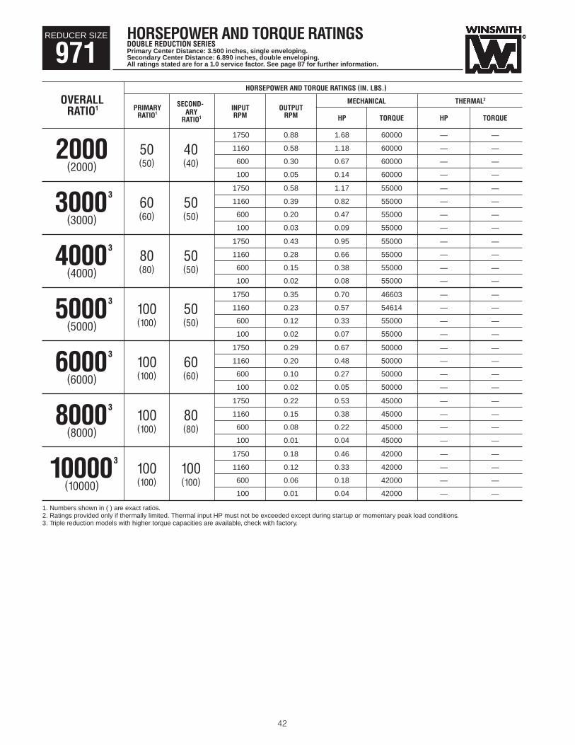
HORSEPOWER AND TORQUE RATINGSDOUBLE REDUCTION SERIESPrimary Center Distance: 3.500 inches, single enveloping.Secondary Center Distance: 6.890 inches, double enveloping.All ratings stated are for a 1.0 service factor. See page 87 for further information.
42
REDUCER SIZE
971HORSEPOWER AND TORQUE RATINGS (IN. LBS.)
OVERALL SECOND- MECHANICAL THERMAL2
RATIO1 PRIMARY ARY INPUT OUTPUTRATIO1
RATIO1 RPM RPM HP TORQUE HP TORQUE
1750 0.88 1.68 60000 — —
50 40 1160 0.58 1.18 60000 — —2000(50) (40) 600 0.30 0.67 60000 — —(2000)
100 0.05 0.14 60000 — —
1750 0.58 1.17 55000 — —
60 50 1160 0.39 0.82 55000 — —330003
(60) (50) 600 0.20 0.47 55000 — —(3000)100 0.03 0.09 55000 — —
1750 0.43 0.95 55000 — —
80 50 1160 0.28 0.66 55000 — —340003
(80) (50) 600 0.15 0.38 55000 — —(4000)100 0.02 0.08 55000 — —
1750 0.35 0.70 46603 — —
100 50 1160 0.23 0.57 54614 — —350003
(100) (50) 600 0.12 0.33 55000 — —(5000)100 0.02 0.07 55000 — —
1750 0.29 0.67 50000 — —
100 60 1160 0.20 0.48 50000 — —360003
(100) (60) 600 0.10 0.27 50000 — —(6000)100 0.02 0.05 50000 — —
1750 0.22 0.53 45000 — —
100 80 1160 0.15 0.38 45000 — —380003
(100) (80) 600 0.08 0.22 45000 — —(8000)100 0.01 0.04 45000 — —
1750 0.18 0.46 42000 — —
100 100 1160 0.12 0.33 42000 — —3100003
(100) (100) 600 0.06 0.18 42000 — —(10000)100 0.01 0.04 42000 — —
1. Numbers shown in ( ) are exact ratios.2. Ratings provided only if thermally limited. Thermal input HP must not be exceeded except during startup or momentary peak load conditions.3. Triple reduction models with higher torque capacities are available, check with factory.

OVERHUNG LOAD CAPACITIES4 (LBS.) THRUST CAPACITIES (LBS.)
INPUT SHAFT OUTPUT SHAFT OUTPUT SHAFT OVERALLALL DBD5 DVD5 DVD5 †DSFD6 †DSFD6 DBD, DLD AWAY
INPUT RATIOMODELS5 DTD5 SHAFT UP SHAFT DOWN BASE SIDE COVER SIDE DLD5
DTD, DVD7 DSFD7FROM BASE
RPM
500 12500 12500 12500 12000 12000 17500 8500 13000 10000 1750
500 12500 12500 12500 12000 12000 17500 8500 13000 10000 1160
500 12500 12500 12500 12000 12000 17500 8500 13000 10000 6002000
500 12500 12500 12500 12000 12000 17500 8500 13000 10000 100(2000)
500 12500 12500 12500 12000 12000 17500 8500 13000 10000 1750
500 12500 12500 12500 12000 12000 17500 8500 13000 10000 1160
500 12500 12500 12500 12000 12000 17500 8500 13000 10000 600
330003
500 12500 12500 12500 12000 12000 17500 8500 13000 10000 100(3000)
500 12500 12500 12500 12000 12000 17500 8500 13000 10000 1750
500 12500 12500 12500 12000 12000 17500 8500 13000 10000 1160
500 12500 12500 12500 12000 12000 17500 8500 13000 10000 600
340003
500 12500 12500 12500 12000 12000 17500 8500 13000 10000 100(4000)
500 12500 12500 12500 12000 12000 17500 8500 13000 10000 1750
500 12500 12500 12500 12000 12000 17500 8500 13000 10000 1160
500 12500 12500 12500 12000 12000 17500 8500 13000 10000 600
350003
500 12500 12500 12500 12000 12000 17500 8500 13000 10000 100(5000)
500 12500 12500 12500 12000 12000 17500 8500 13000 10000 1750
500 12500 12500 12500 12000 12000 17500 8500 13000 10000 1160
500 12500 12500 12500 12000 12000 17500 8500 13000 10000 600
360003
500 12500 12500 12500 12000 12000 17500 8500 13000 10000 100(6000)
500 12500 12500 12500 12000 12000 17500 8500 13000 10000 1750
500 12500 12500 12500 12000 12000 17500 8500 13000 10000 1160
500 12500 12500 12500 12000 12000 17500 8500 13000 10000 600
380003
500 12500 12500 12500 12000 12000 17500 8500 13000 10000 100(8000)
500 12500 12500 12500 12000 12000 17500 8500 13000 10000 1750
500 12500 12500 12500 12000 12000 17500 8500 13000 10000 1160
500 12500 12500 12500 12000 12000 17500 8500 13000 10000 600100003
500 12500 12500 12500 12000 12000 17500 8500 13000 10000 100(10000)
4. (Shaded area) Chart values are based on bearing capacity or shaft strength only. Allowable overhung loads may be less depending upon direction of chain pulland type of foundation bolts. See page 88 for further information.
5. Overhung load given at one shaft diameter from housing or mounting base (DV).6. Overhung load given at 4.438 inches from the end face of the slow speed shaft. Maximum values are based on the largest bore. Use of smaller diameter may limit
OHL due to shaft strength.7. Values shown are applicable for either direction of thrust (into or away from unit).
43
SHAFT OVERHUNG AND THRUST LOAD CAPACITIESDOUBLE REDUCTION SERIES
REDUCER SIZE
971

HORSEPOWER AND TORQUE RATINGSSINGLE REDUCTION SERIESCenter Distance: 7.874 inches.All ratings stated are for a 1.0 service factor. See page 87 for further information.
44
REDUCER SIZE
981HORSEPOWER AND TORQUE RATINGS (IN. LBS.)
MECHANICAL2 THERMAL3 FAN-COOLED—THERMAL3
RATIO1INPUT OUTPUT
OUTPUT INPUT OUTPUT INPUT OUTPUT INPUTRPM RPMTORQUE HP EFF. TORQUE HP EFF. TORQUE HP EFF.
1750 350 34429 198.5 96 9715 57.07 95 17926 104.1 96
1450 290 41806 199.7 96 13788 66.57 95 20908 100.4 96
1160 232 48936 187.2 96 18388 70.81 96 24291 93.30 965 870 174 56067 161.5 96 23502 68.01 95 27948 80.77 96
600 120 62706 125.4 95 30685 61.55 95 33422 67.00 95(5)300 60 70082 71.27 94 47148 48.01 94 47148 48.01 94
100 20 75000 26.31 91 75000 26.31 91 75000 26.31 91
1750 219 39779 144.7 95 12655 47.05 93 23352 85.57 95
1450 181 47456 143.0 95 17769 54.22 94 26945 81.67 95
1160 145 54876 132.6 95 23437 57.04 95 30961 75.12 958 870 109 62297 113.4 95 29646 54.28 94 35253 64.44 94
600 75 69206 87.67 94 38460 48.89 94 41890 53.22 94(8)300 38 76882 49.73 92 59405 38.47 92 59405 38.47 92
100 13 82000 18.39 88 82000 18.39 88 82000 18.39 88
1750 175 50253 147.1 95 13712 41.20 92 25302 74.77 94
1450 145 56571 137.3 95 19193 47.28 93 29105 71.14 94
1160 116 62678 122.0 95 25240 49.58 93 33343 65.25 9410 870 87 68785 101.0 94 31846 47.08 93 37870 55.88 94
600 60 74471 76.22 93 41271 42.41 93 44953 46.16 93(10)300 30 80788 42.35 91 63924 33.55 91 63924 33.55 91
100 10 85000 15.52 87 85000 15.52 87 85000 15.52 87
1750 117 53844 106.9 93 15357 31.55 90 28337 56.97 92
1450 97 59509 98.05 93 21404 35.95 91 32458 53.97 92
1160 77 64985 85.99 93 28037 37.53 92 37038 49.33 9215 870 58 70461 70.52 92 35268 35.58 91 41939 42.20 92
600 40 75559 52.87 91 45670 32.11 90 49744 34.94 90(15)300 20 81224 29.32 88 71090 25.68 88 71090 25.68 88
100 6.7 85000 10.81 83 85000 10.81 83 85000 10.81 83
1750 88 54515 82.99 91 15394 24.50 87 28405 43.95 90
1450 73 60603 76.58 91 21460 27.81 89 32543 41.62 90
1160 58 66488 67.55 91 28116 29.00 89 37142 38.06 9020 870 44 72374 55.75 90 35372 27.54 89 42062 32.64 89
600 30 77853 42.10 88 45805 24.93 88 49891 27.12 88(20)300 15 83941 23.62 85 71280 20.09 85 71280 20.09 85
100 5.0 88000 8.86 79 88000 8.86 79 88000 8.86 79
1750 70 57076 69.81 91 19039 24.27 87 35132 43.54 90
1450 58 62335 63.29 91 26327 27.35 89 39923 40.92 90
1160 46 67419 55.05 90 34261 28.35 89 45260 37.21 9025 870 35 72502 44.92 89 42930 26.83 88 51050 31.79 89
600 24 77235 33.60 88 55669 24.32 87 60634 26.46 87(25)300 12 82494 18.65 84 82494 18.65 84 82494 18.65 84
100 4.0 86000 6.91 79 86000 6.91 79 86000 6.91 79
1. Numbers shown in ( ) are exact ratios.2. Mechanical ratings apply to both non-fan cooled and fan cooled models.3. Thermal input HP must not be exceeded except during startup or momentary peak load conditions.

OVERHUNG LOAD CAPACITIES4 (LBS.) THRUST CAPACITIES (LBS.)
INPUT SHAFT OUTPUT SHAFT OUTPUT SHAFT
ALL DV 5 DV5 †DSF6 †DSF6 DB, DL AWAYRATIO
MODELS5 DB5 DT5SHAFT UP SHAFT DOWN BASE SIDE COVER SIDE DL5
DT, DV7 DSF7FROM BASE
1810 5981 5981 5981 5824 4600 4600 10035 4882 7458 6105
1762 5977 5977 5977 5820 4585 4585 10467 4475 7125 5771
1786 6096 6096 6096 5935 4665 4665 11049 4216 6981 5601
1928 6404 6404 6404 6236 4891 4891 11887 4161 7109 5663 52269 7129 7129 7129 6942 5337 5337 13139 4587 7668 6154
2800 9263 9263 9263 9019 6679 6679 16418 6508 9875 8448(5)
2800 14050 14050 14050 13680 9755 9755 21000 9500 15000 10000
1873 6683 6683 6683 6507 5178 5178 11039 5981 8875 7302
1671 6770 6770 6770 6592 5241 5241 11561 5776 8780 7174
1546 6985 6985 6985 6801 5405 5405 12246 5720 8882 7217
1539 7612 7612 7612 7411 5728 5728 13360 6118 9282 7657 81740 8657 8657 8657 8429 6326 6326 15115 6994 10213 8735
2610 11164 11164 11164 10870 8172 8172 18858 9435 13484 10000(8)
2800 16000 16000 16000 15100 12112 12112 21000 9500 15000 10000
1451 6525 6525 6525 6353 5099 5099 11259 5749 8730 7093
1351 6746 6746 6746 6569 5276 5276 11879 5793 8930 7221
1324 7253 7253 7253 7062 5554 5554 12751 6161 9326 7601
1415 8053 8053 8053 7841 5999 5999 14120 6848 10032 8443 101709 9285 9285 9285 9040 6864 6864 16046 8022 11548 9830
2682 12287 12287 12287 11964 8934 8934 20207 9500 15000 10000(10)
2800 16000 16000 16000 15100 13393 13393 21000 9500 15000 10000
1520 7436 7436 7436 7240 5786 5786 12365 7231 10442 8572
1483 7916 7916 7916 7708 6063 6063 13265 7648 10897 9089
1517 8584 8584 8584 8357 6467 6467 14407 8275 11598 9841
1670 9575 9575 9575 9323 7210 7210 15980 9257 12942 10000 152022 11038 11038 11038 10747 8305 8305 18165 9500 14959 10000
2800 14901 14901 14901 14509 10724 10724 21000 9500 15000 10000(15)
2800 16000 16000 16000 15100 16132 16132 21000 9500 15000 10000
1529 8281 8281 8281 8063 6356 6356 13439 8565 11840 9992
1475 8807 8807 8807 8575 6716 6716 14412 9069 12485 10000
1484 9534 9534 9534 9283 7271 7271 15643 9500 13503 10000
1632 10610 10610 10610 10330 8086 8086 17338 9500 15000 10000 201970 12397 12397 12397 12070 9277 9277 19811 9500 15000 10000
2800 16000 16000 16000 15100 12138 12138 21000 9500 15000 10000(20)
2800 16000 16000 16000 15100 16500 16500 21000 9500 15000 10000
1749 8945 8945 8945 8709 6776 6776 14308 9256 12625 10000
1767 9585 9585 9585 9332 7262 7262 15382 9500 13518 10000
1856 10434 10434 10434 10159 7903 7903 16728 9500 14709 10000
2063 11717 11717 11717 11408 8818 8818 18564 9500 15000 10000 252465 13832 13832 13832 13467 10128 10128 21000 9500 15000 10000
2800 16000 16000 16000 15100 13410 13410 21000 9500 15000 10000(25)
2800 16000 16000 16000 15100 16500 16500 21000 9500 15000 10000
4. (Shaded area) Chart values are based on bearing capacity or shaft strength only. Allowable overhung loads may be less depending upon direction of chain pulland type of foundation bolts. See page 88 for further information.
5. Overhung load given at one shaft diameter from housing or mounting base (DV).6. Overhung load given at 4.438 inches from the end face of the slow speed shaft. Maximum values are based on the largest bore. Use of smaller diameter may limit
OHL due to shaft strength.7. Values shown are applicable for either direction of thrust (into or away from unit).
45
SHAFT OVERHUNG AND THRUST LOAD CAPACITIESSINGLE REDUCTION SERIES
REDUCER SIZE
981

HORSEPOWER AND TORQUE RATINGSSINGLE REDUCTION SERIESCenter Distance: 7.874 inches.All ratings stated are for a 1.0 service factor. See page 87 for further information.
46
REDUCER SIZE
981HORSEPOWER AND TORQUE RATINGS (IN. LBS.)
MECHANICAL2 THERMAL3 FAN-COOLED—THERMAL3
RATIO1INPUT OUTPUT
OUTPUT INPUT OUTPUT INPUT OUTPUT INPUTRPM RPMTORQUE HP EFF. TORQUE HP EFF. TORQUE HP EFF.
1750 58 56300 58.36 89 19425 21.10 85 35844 37.69 88
1450 48 61700 53.10 89 26845 23.71 87 40708 35.40 88
1160 39 66920 46.35 89 34920 24.55 87 46132 32.19 8830 870 29 72140 37.98 87 43750 23.25 87 52025 27.55 87
600 20 77000 28.53 86 56750 21.13 85 61812 22.98 85(30)300 10 82400 15.96 82 82400 15.96 82 82400 15.96 82
100 3.3 86000 5.97 76 86000 5.97 76 86000 5.97 76
1750 44 55397 44.82 86 18664 16.08 81 34439 28.42 84
1450 36 60779 40.86 86 25832 17.98 83 39172 26.71 84
1160 29 65982 35.76 85 33640 18.60 83 44440 24.33 8440 870 22 71185 29.45 83 42165 17.67 82 50140 20.91 83
600 15 76029 22.29 81 54653 16.13 81 59528 17.53 81(40)300 7.5 81412 12.65 77 81412 12.65 77 81412 12.65 77
100 2.5 85000 4.84 70 85000 4.84 70 85000 4.84 70
1750 35 54659 36.51 83 19227 13.80 77 35479 24.22 81
1450 29 59812 33.21 83 26586 15.36 80 40315 22.73 82
1160 23 64793 29.04 82 34597 15.86 80 45704 20.71 8150 870 17 69774 23.95 80 43350 15.09 79 51550 17.84 80
600 12 74412 18.18 78 56215 13.83 77 61229 15.03 78(50)300 6.0 79565 10.39 73 79565 10.39 73 79565 10.39 73
100 2.0 83000 4.03 65 83000 4.03 65 83000 4.03 65
1750 29 54085 31.03 81 19685 12.23 75 36323 21.32 79
1450 24 58797 28.05 80 27198 13.55 77 41244 20.00 79
1160 19 63352 24.43 80 35374 13.97 78 46731 18.22 7960 870 15 67906 20.11 78 44316 13.32 77 52698 15.73 77
600 10 72147 15.27 75 57492 12.25 75 62620 13.30 75(60)300 5.0 76859 8.77 70 76859 8.77 70 76859 8.77 70
100 1.7 80000 3.42 62 80000 3.42 62 80000 3.42 62
1750 22 52044 23.47 77 21810 10.69 71 40244 18.48 76
1450 18 55309 20.75 77 30046 11.76 73 45562 17.29 76
1160 15 58465 17.76 76 39003 12.10 74 51525 15.74 7580 870 11 61621 14.43 74 48852 11.55 73 58092 13.63 74
600 7.5 64559 10.85 71 63542 10.68 71 64559 10.85 71(80)300 3.8 67824 6.19 65 67824 6.19 65 67824 6.19 65
100 1.3 70000 2.41 58 70000 2.41 58 70000 2.41 58
1750 18 50441 19.19 73 22386 9.34 67 41307 15.98 72
1450 15 53088 16.82 73 30820 10.21 69 46736 14.93 72
1160 12 55647 14.29 72 39995 10.48 70 52835 13.61 72100 870 8.7 58206 11.57 69 50100 10.04 69 58206 11.57 69
600 6.0 60588 8.70 66 60588 8.70 66 60588 8.70 66(100)300 3.0 63235 4.98 61 63235 4.98 61 63235 4.98 61
100 1.0 65000 1.96 53 65000 1.96 53 65000 1.96 53
1. Numbers shown in ( ) are exact ratios.2. Mechanical ratings apply to both non-fan cooled and fan cooled models.3. Thermal input HP must not be exceeded except during startup or momentary peak load conditions.
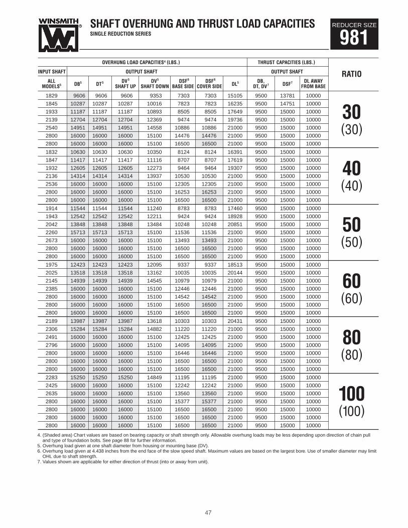
OVERHUNG LOAD CAPACITIES4 (LBS.) THRUST CAPACITIES (LBS.)
INPUT SHAFT OUTPUT SHAFT OUTPUT SHAFT
ALL DV 5 DV5 †DSF6 †DSF6 DB, DL AWAYRATIO
MODELS5 DB5 DT5SHAFT UP SHAFT DOWN BASE SIDE COVER SIDE DL5
DT, DV7 DSF7FROM BASE
1829 9606 9606 9606 9353 7303 7303 15105 9500 13781 10000
1845 10287 10287 10287 10016 7823 7823 16235 9500 14751 10000
1933 11187 11187 11187 10893 8505 8505 17649 9500 15000 10000
2139 12704 12704 12704 12369 9474 9474 19736 9500 15000 10000 302540 14951 14951 14951 14558 10886 10886 21000 9500 15000 10000
2800 16000 16000 16000 15100 14476 14476 21000 9500 15000 10000(30)
2800 16000 16000 16000 15100 16500 16500 21000 9500 15000 10000
1832 10630 10630 10630 10350 8124 8124 16391 9500 15000 10000
1847 11417 11417 11417 11116 8707 8707 17619 9500 15000 10000
1932 12605 12605 12605 12273 9464 9464 19307 9500 15000 10000
2136 14314 14314 14314 13937 10530 10530 21000 9500 15000 10000 402536 16000 16000 16000 15100 12305 12305 21000 9500 15000 10000
2800 16000 16000 16000 15100 16253 16253 21000 9500 15000 10000(40)
2800 16000 16000 16000 15100 16500 16500 21000 9500 15000 10000
1914 11544 11544 11544 11240 8783 8783 17460 9500 15000 10000
1943 12542 12542 12542 12211 9424 9424 18928 9500 15000 10000
2042 13848 13848 13848 13484 10248 10248 20851 9500 15000 10000
2260 15713 15713 15713 15100 11536 11536 21000 9500 15000 10000 502673 16000 16000 16000 15100 13493 13493 21000 9500 15000 10000
2800 16000 16000 16000 15100 16500 16500 21000 9500 15000 10000(50)
2800 16000 16000 16000 15100 16500 16500 21000 9500 15000 10000
1975 12423 12423 12423 12095 9337 9337 18513 9500 15000 10000
2025 13518 13518 13518 13162 10035 10035 20144 9500 15000 10000
2145 14939 14939 14939 14545 10979 10979 21000 9500 15000 10000
2385 16000 16000 16000 15100 12446 12446 21000 9500 15000 10000 602800 16000 16000 16000 15100 14542 14542 21000 9500 15000 10000
2800 16000 16000 16000 15100 16500 16500 21000 9500 15000 10000(60)
2800 16000 16000 16000 15100 16500 16500 21000 9500 15000 10000
2189 13987 13987 13987 13618 10303 10303 20431 9500 15000 10000
2306 15284 15284 15284 14882 11220 11220 21000 9500 15000 10000
2491 16000 16000 16000 15100 12425 12425 21000 9500 15000 10000
2796 16000 16000 16000 15100 14095 14095 21000 9500 15000 10000 802800 16000 16000 16000 15100 16446 16446 21000 9500 15000 10000
2800 16000 16000 16000 15100 16500 16500 21000 9500 15000 10000(80)
2800 16000 16000 16000 15100 16500 16500 21000 9500 15000 10000
2283 15250 15250 15250 14849 11195 11195 21000 9500 15000 10000
2425 16000 16000 16000 15100 12242 12242 21000 9500 15000 10000
2635 16000 16000 16000 15100 13560 13560 21000 9500 15000 10000
2800 16000 16000 16000 15100 15377 15377 21000 9500 15000 10000 1002800 16000 16000 16000 15100 16500 16500 21000 9500 15000 10000
2800 16000 16000 16000 15100 16500 16500 21000 9500 15000 10000(100)
2800 16000 16000 16000 15100 16500 16500 21000 9500 15000 10000
4. (Shaded area) Chart values are based on bearing capacity or shaft strength only. Allowable overhung loads may be less depending upon direction of chain pulland type of foundation bolts. See page 88 for further information.
5. Overhung load given at one shaft diameter from housing or mounting base (DV).6. Overhung load given at 4.438 inches from the end face of the slow speed shaft. Maximum values are based on the largest bore. Use of smaller diameter may limit
OHL due to shaft strength.7. Values shown are applicable for either direction of thrust (into or away from unit).
47
SHAFT OVERHUNG AND THRUST LOAD CAPACITIESSINGLE REDUCTION SERIES
REDUCER SIZE
981

HORSEPOWER AND TORQUE RATINGSDOUBLE REDUCTION SERIESPrimary Center Distance: 2.625 inches, single enveloping.Secondary Center Distance: 3.937 inches, double enveloping.All ratings stated are for a 1.0 service factor. See page 87 for further information.
48
REDUCER SIZE
981HORSEPOWER AND TORQUE RATINGS (IN. LBS.)
SECOND- MECHANICAL THERMAL2
RATIO1PRIMARY ARY INPUT OUTPUT
RATIO1
RATIO1 RPM RPM HP TORQUE HP TORQUE
1750 11.70 17.97 77667 — —
5 30 1160 7.73 13.24 83624 — —150(5) (30) 600 4.00 7.41 85640 — —(150)
100 0.67 1.42 86000 — —
1750 8.75 14.90 80515 — —
5 40 1160 5.80 10.57 82632 — —200(5) (40) 600 3.00 6.00 84641 — —(200)
100 0.50 1.18 85000 — —
1750 5.83 10.48 84650 — —
10 30 1160 3.87 7.29 85712 — —300(10) (30) 600 2.00 4.01 86000 — —(300)
100 0.33 0.77 86000 — —
1750 3.50 6.54 84058 — —
20 25 1160 2.32 4.60 86000 — —500(20) (25) 600 1.20 2.52 86000 — —(500)
100 0.20 0.49 86000 — —
1750 2.33 4.83 86000 — —
25 30 1160 1.55 3.34 86000 — —750(25) (30) 600 0.80 1.84 86000 — —(750)
100 0.13 0.37 86000 — —
1750 1.75 3.96 85000 — —
25 40 1160 1.16 2.75 85000 — —1000(25) (40) 600 0.60 1.54 85000 — —(1000)
100 0.10 0.31 85000 — —
1750 1.17 2.71 86000 — —
50 30 1160 0.77 1.88 86000 — —1500(50) (30) 600 0.40 1.05 86000 — —(1500)
100 0.07 0.21 86000 — —
1. Numbers shown in ( ) are exact ratios.2. Ratings provided only if thermally limited. Thermal input HP must not be exceeded except during startup or momentary peak load conditions.
Primary Center Distance: 4.250 inches single enveloping. Secondary Center Distance: 7.874 inches double enveloping.

OVERHUNG LOAD CAPACITIES3(LBS.) THRUST CAPACITIES (LBS.)
INPUT SHAFT OUTPUT SHAFT OUTPUT SHAFT
ALL DBD4 DVD4 DVD4 †DSFD5 †DSFD5 DBD, DLD AWAYINPUT RATIO
MODELS4 DTD5 SHAFT UP SHAFT DOWN BASE SIDE COVER SIDE DLD4DTD, DVD6 DSFD6
FROM BASERPM
1000 16000 16000 15100 13614 13614 21000 9500 15000 10000 1750
1000 16000 16000 15100 15841 15841 21000 9500 15000 10000 1160
1000 16000 16000 15100 16500 16500 21000 9500 15000 10000 600150
1000 16000 16000 15100 16500 16500 21000 9500 15000 10000 100(150)
1000 16000 16000 15100 15307 15307 21000 9500 15000 10000 1750
1000 16000 16000 15100 16500 16500 21000 9500 15000 10000 1160
1000 16000 16000 15100 16500 16500 21000 9500 15000 10000 600200
1000 16000 16000 15100 16500 16500 21000 9500 15000 10000 100(200)
1000 16000 16000 15100 16500 16500 21000 9500 15000 10000 1750
1000 16000 16000 15100 16500 16500 21000 9500 15000 10000 1160
1000 16000 16000 15100 16500 16500 21000 9500 15000 10000 600300
1000 16000 16000 15100 16500 16500 21000 9500 15000 10000 100(300)
1000 16000 16000 15100 16500 16500 21000 9500 15000 10000 1750
1000 16000 16000 15100 16500 16500 21000 9500 15000 10000 1160
879 16000 16000 15100 16500 16500 21000 9500 15000 10000 600500
1000 16000 16000 15100 16500 16500 21000 9500 15000 10000 100(500)
1000 16000 16000 15100 16500 16500 21000 9500 15000 10000 1750
1000 16000 16000 15100 16500 16500 21000 9500 15000 10000 1160
697 16000 16000 15100 16500 16500 21000 9500 15000 10000 600750
1000 16000 16000 15100 16500 16500 21000 9500 15000 10000 100(750)
1000 16000 16000 15100 16500 16500 21000 9500 15000 10000 1750
1000 16000 16000 15100 16500 16500 21000 9500 15000 10000 1160
697 16000 16000 15100 16500 16500 21000 9500 15000 10000 6001000
1000 16000 16000 15100 16500 16500 21000 9500 15000 10000 100(1000)
1000 16000 16000 15100 16500 16500 21000 9500 15000 10000 1750
1000 16000 16000 15100 16500 16500 21000 9500 15000 10000 1160
1000 16000 16000 15100 16500 16500 21000 9500 15000 10000 6001500
1000 16000 16000 15100 16500 16500 21000 9500 15000 10000 100(1500)
3. (Shaded area) Chart values are based on bearing capacity or shaft strength only. Allowable overhung loads may be less depending upon location and direction ofchain pull and type of foundation bolts. See page 88 for further information.
4. Overhung load given at one shaft diameter from housing or mounting base (DV).5. Overhung load given at 4.438 inches from the end face of the slow speed shaft. Maximum values are based on the largest bore. Use of smaller diameter may limit
OHL due to shaft strength.6. Values shown are applicable for either direction of thrust (into or away from unit).
49
SHAFT OVERHUNG AND THRUST LOAD CAPACITIESDOUBLE REDUCTION SERIES
REDUCER SIZE
981

HORSEPOWER AND TORQUE RATINGSDOUBLE REDUCTION SERIESPrimary Center Distance: 2.625 inches, single enveloping.Secondary Center Distance: 3.937 inches, double enveloping.All ratings stated are for a 1.0 service factor. See page 87 for further information.
50
REDUCER SIZE
981HORSEPOWER AND TORQUE RATINGS (IN. LBS.)
SECOND- MECHANICAL THERMAL2
RATIO1PRIMARY ARY INPUT OUTPUT
RATIO1
RATIO1 RPM RPM HP TORQUE HP TORQUE
1750 0.88 2.25 85000 — —
50 40 1160 0.58 1.57 85000 — —2000(50) (40) 600 0.30 0.89 85000 — —(2000)
100 0.05 0.18 85000 — —
1750 0.58 1.65 83000 — —
60 50 1160 0.39 1.15 83000 — —3000(60) (50) 600 0.20 0.66 83000 — —(3000)
100 0.03 0.13 83000 — —
1750 0.43 1.33 83000 — —
80 50 1160 0.28 0.93 83000 — —4000(80) (50) 600 0.15 0.53 83000 — —(4000)
100 0.02 0.11 83000 — —
1750 0.35 1.02 74644 — —
100 50 1160 0.23 0.80 83000 — —350003
(100) (50) 600 0.12 0.46 83000 — —(5000)100 0.02 0.09 83000 — —
1750 0.29 0.98 80000 — —
100 60 1160 0.20 0.70 80000 — —360003
(100) (60) 600 0.10 0.40 80000 — —(6000)100 0.02 0.08 80000 — —
1750 0.22 0.72 70000 — —
100 80 1160 0.15 0.51 70000 — —380003
(100) (80) 600 0.08 0.29 70000 — —(8000)100 0.01 0.06 70000 — —
1750 0.18 0.60 65000 — —
100 100 1160 0.12 0.43 65000 — —3100003
(100) (100) 600 0.06 0.24 65000 — —(10000)100 0.01 0.05 65000 — —
1. Numbers shown in ( ) are exact ratios.2. Ratings provided only if thermally limited. Thermal input HP must not be exceeded except during startup or momentary peak load conditions.3. Triple reduction models with higher torque capacities are available, check with factory.
Primary Center Distance: 4.250 inches single enveloping. Secondary Center Distance: 7.874 inches double enveloping.

OVERHUNG LOAD CAPACITIES4 (LBS.) THRUST CAPACITIES (LBS.)
INPUT SHAFT OUTPUT SHAFT OUTPUT SHAFT
ALL DBD5 DVD5 DVD5 †DSFD6 †DSFD6 DBD, DLD AWAYINPUT RATIO
MODELS5 DTD5 SHAFT UP SHAFT DOWN BASE SIDE COVER SIDE DLD5DTD, DVD7 DSFD7
FROM BASERPM
1000 16000 16000 15100 16500 16500 21000 9500 15000 10000 1750
1000 16000 16000 15100 16500 16500 21000 9500 15000 10000 1160
1000 16000 16000 15100 16500 16500 21000 9500 15000 10000 6002000
1000 16000 16000 15100 16500 16500 21000 9500 15000 10000 100(2000)
1000 16000 16000 15100 16500 16500 21000 9500 15000 10000 1750
1000 16000 16000 15100 16500 16500 21000 9500 15000 10000 1160
1000 16000 16000 15100 16500 16500 21000 9500 15000 10000 6003000
1000 16000 16000 15100 16500 16500 21000 9500 15000 10000 100(3000)
1000 16000 16000 15100 16500 16500 21000 9500 15000 10000 1750
1000 16000 16000 15100 16500 16500 21000 9500 15000 10000 1160
1000 16000 16000 15100 16500 16500 21000 9500 15000 10000 6004000
1000 16000 16000 15100 16500 16500 21000 9500 15000 10000 100(4000)
1000 16000 16000 15100 16500 16500 21000 9500 15000 10000 1750
1000 16000 16000 15100 16500 16500 21000 9500 15000 10000 1160
1000 16000 16000 15100 16500 16500 21000 9500 15000 10000 600
350003
1000 16000 16000 15100 16500 16500 21000 9500 15000 10000 100(5000)
1000 16000 16000 15100 16500 16500 21000 9500 15000 10000 1750
1000 16000 16000 15100 16500 16500 21000 9500 15000 10000 1160
1000 16000 16000 15100 16500 16500 21000 9500 15000 10000 600
360003
1000 16000 16000 15100 16500 16500 21000 9500 15000 10000 100(6000)
1000 16000 16000 15100 16500 16500 21000 9500 15000 10000 1750
1000 16000 16000 15100 16500 16500 21000 9500 15000 10000 1160
1000 16000 16000 15100 16500 16500 21000 9500 15000 10000 600
380003
1000 16000 16000 15100 16500 16500 21000 9500 15000 10000 100(8000)
1000 16000 16000 15100 16500 16500 21000 9500 15000 10000 1750
1000 16000 16000 15100 16500 16500 21000 9500 15000 10000 1160
1000 16000 16000 15100 16500 16500 21000 9500 15000 10000 600100003
1000 16000 16000 15100 16500 16500 21000 9500 15000 10000 100(10000)
4. (Shaded area) Chart values are based on bearing capacity or shaft strength only. Allowable overhung loads may be less depending upon location and direction ofchain pull and type of foundation bolts. See page 88 for further information.
5. Overhung load given at one shaft diameter from housing or mounting base (DV).6. Overhung load given at 4.438 inches from the end face of the slow speed shaft. Maximum values are based on the largest bore. Use of smaller diameter may limit
OHL due to shaft strength.7. Values shown are applicable for either direction of thrust (into or away from unit).
51
SHAFT OVERHUNG AND THRUST LOAD CAPACITIESDOUBLE REDUCTION SERIES
REDUCER SIZE
981

DB/FDB
52
SIZE A B C1 D E F G H J K K3 L° L1 M O PHIGH SPEED SHAFT SLOW SPEED SHAFT
DIA.
941 10.00 12.76 3.937 5.75 4.13 5.25 1.38 .69 9.69 9.74 7.88 5.78 7.81 9.00 15.69 9.25
951 11.25 15.29 4.921 5.75 4.50 6.38 1.50 .81 10.67 10.00 7.88 6.77 8.56 9.73 17.56 9.38
961 12.75 16.58 5.906 6.25 5.13 6.88 1.69 .94 12.16 12.00 9.63 8.47 10.69 11.10 19.91 11.50
971 15.25 19.40 6.890 7.88 6.25 8.13 2.00 1.06 14.77 13.38 10.75 9.39 12.22 13.25 23.88 13.50
981 16.75 22.19 7.874 8.50 6.75 9.25 2.13 1.19 16.37 15.13 11.50 10.45 12.69 15.50 26.50 15.50
U* N V KEYWAY W* S T KEYWAY
1.500 3.22 3.25 3⁄8 x 3⁄16 2.250 4.38 4.19 1⁄ 2 x 1⁄4
1.500 3.00 3.06 3⁄8 x 3⁄16 2.500 4.38 4.13 5⁄ 8 x 5⁄16
1.750 3.17 3.12 3⁄8 x 3⁄16 3.125 5.50 5.25 3⁄ 4 x 3⁄8
1.750 4.25 4.25 3⁄8 x 3⁄16 3.500 6.81 6.56 7⁄8 x 7⁄16
2.000 5.60 5.47 1⁄2 x 1⁄4 3.875 7.94 7.69 1 x 1⁄2
GEAR RATIO RANGE 5:1 THRU 100:1DOUBLE REDUCTION VERSION . . . . . . . . . . . . . . . . . . . . PAGE 64††Weights are approximate and include shipping container.††Add 20 pounds if adapter ring is furnished with motor adapter.
GENERAL INFORMATION
*Shaft diameter tolerance +.000, -.001. °Distance to high speed cap on units without a fan. (DB)
SHAFT ARRANGEMENTS AND RELATIVE SHAFT ROTATIONS
D-90® TYPEDE®
The input shaft may be driven in either direction.
MODEL DB MODEL FDB
MODEL† 941 951 961 971 981
DB SHIPPING WEIGHT 179 285 440 660 860
FDB SHIPPING WEIGHT 183 290 445 666 868
CDB SHIPPING WEIGHT†† 206 320 476 696 898
CFDB SHIPPING WEIGHT†† 210 325 481 702 906
APPROX. OIL CAPACITY (QUARTS) 2.1 2.5 3.5 8 10
DB/FDB Models CDB/CFDB Models
ASSEMBLY LROPTIONAL
ASSEMBLY RSTANDARD
ASSEMBLY LSTANDARD
ASSEMBLY LROPTIONAL
ASSEMBLY RSTANDARD
ASSEMBLY LSTANDARD

CDB/CFDB
53
D-90® TYPEDE®
The input shaft may be driven in either direction.
UNIT SIZE N.E.M.A. AB AJ AK BB BD BE BF U N V M M1 KEYWAY CONFIGURATIONSINGLE REDUCTION FRAME SIZE
182TC - 184TC 213C - 215C 5.00 7.25 8.5005 / 8.5025 .19 9.00 .50 .53 1.500 2.63 3.25 9.00 13.00 3⁄8 x 3⁄16 FIGURE 1*
941 213TC - 215TC 5.00 7.25 8.5005 / 8.5025 .19 9.00 .50 .53 1.500 2.63 3.25 9.00 13.00 3⁄8 x 3⁄16 FIGURE 1*
254TC - 256TC 254UC - 256UC 5.00 7.25 8.5005 / 8.5025 .19 9.00 1.44 .53 1.500 2.63 3.25 9.00 13.94 3⁄8 x 3⁄16 FIGURE 2*
182TC - 184TC 213C - 215C 5.00 7.25 8.5005 / 8.5025 .19 9.00 .50 .53 1.500 2.93 3.06 9.73 13.75 3⁄8 x 3⁄16 FIGURE 1*
951213TC - 215TC 5.00 7.25 8.5005 / 8.5025 .19 9.00 .50 .53 1.500 2.93 3.06 9.73 13.75 3⁄8 x 3⁄16 FIGURE 1*
254TC - 256TC 254UC - 256UC 5.00 7.25 8.5005 / 8.5025 .19 9.00 1.44 .53 1.500 2.93 3.06 9.73 14.69 3⁄8 x 3⁄16 FIGURE 2*
284TC - 286TC 284UC - 286UC 5.00 9.00 10.5005 / 10.5025 .19 11.00 .81 .53 1.500 2.93 3.06 9.73 15.44 3⁄8 x 3⁄16 FIGURE 3*
213TC - 215TC 5.00 7.25 8.5005 / 8.5025 .19 9.00 .50 .53 1.750 3.05 3.12 11.10 15.88 3⁄8 x 3⁄16 FIGURE 1*
961 254TC - 256TC 254UC - 256UC 5.00 7.25 8.5005 / 8.5025 .19 9.00 .50 .53 1.750 3.05 3.12 11.10 15.88 3⁄8 x 3⁄16 FIGURE 1*
284TC - 286TC 284UC - 286UC 5.00 9.00 10.5005 / 10.5025 .19 11.00 .25 .53 1.750 3.05 3.12 11.10 17.00 3⁄8 x 3⁄16 FIGURE 3*
213TC - 215TC 5.00 7.25 8.5005 / 8.5025 .19 9.00 .50 .53 1.750 3.77 3.63 12.63 16.88 3⁄8 x 3⁄16 FIGURE 1*
971254TC - 256TC 254UC - 256UC 5.00 7.25 8.5005 / 8.5025 .19 9.00 .50 .53 1.750 3.27 3.13 12.13 16.88 3⁄8 x 3⁄16 FIGURE 1*
284UC - 286UC 5.00 9.00 10.5005 / 10.5025 .19 11.00 .81 .53 1.750 3.77 3.63 12.63 18.56 3⁄8 x 3⁄16 FIGURE 3*
284TC - 286TC 5.00 9.00 10.5005 / 10.5025 .19 11.00 .25 .53 1.750 3.77 3.63 12.63 18.00 3⁄8 x 3⁄16 FIGURE 3*
213TC - 215TC 5.00 7.25 8.5005 / 8.5025 .19 9.00 .50 .53 2.000 3.66 3.47 13.50 17.88 1⁄2 x 1⁄4 FIGURE 1*
981254TC - 256TC 254UC - 256UC 5.00 7.25 8.5005 / 8.5025 .19 9.00 .50 .53 2.000 3.29 3.09 13.13 17.88 1⁄2 x 1⁄4 FIGURE 1*
284UC - 286UC 5.00 9.00 10.5005 / 10.5025 .19 11.00 .50 .53 2.000 3.29 3.09 13.13 19.00 1⁄2 x 1⁄4 FIGURE 3*
284TC - 286TC 5.00 9.00 10.5005 / 10.5025 .19 11.00 .50 .53 2.000 3.66 3.47 13.50 19.00 1⁄2 x 1⁄4 FIGURE 3*
*Adapter ring furnished with motor adapter.
If coupling selection differs from chart, input and/or motor shaft may need alteration.
L-SERIES LOVEJOY COUPLING SELECTION VS. FRAME SIZE (Coupling not provided with unit.)
FRAMEUNIT SIZE
182TC - 184TC 213C - 215C 213TC - 215TC 254UC - 256UC 254TC - 256TC 284UC - 286UC 284TC - 286TC
941 L-110 L-110 L-110 L-110 L-150 — —
951 L-110 L-110 L-110 L-110 L-150 L-150 L-190
961 L-150 L-150 L-150 L-150 L-150 L-190 L-190
971 — L-150 L-150 L-150 L-150 L-190 L-190
981 — L-190 L-190 L-190 L-190 L-190 L-190
MODEL CDB MODEL CFDB
FIG. 1 FIG. 2FIG. 3
OBSOLETEN.E.M.A.
FRAME SIZE
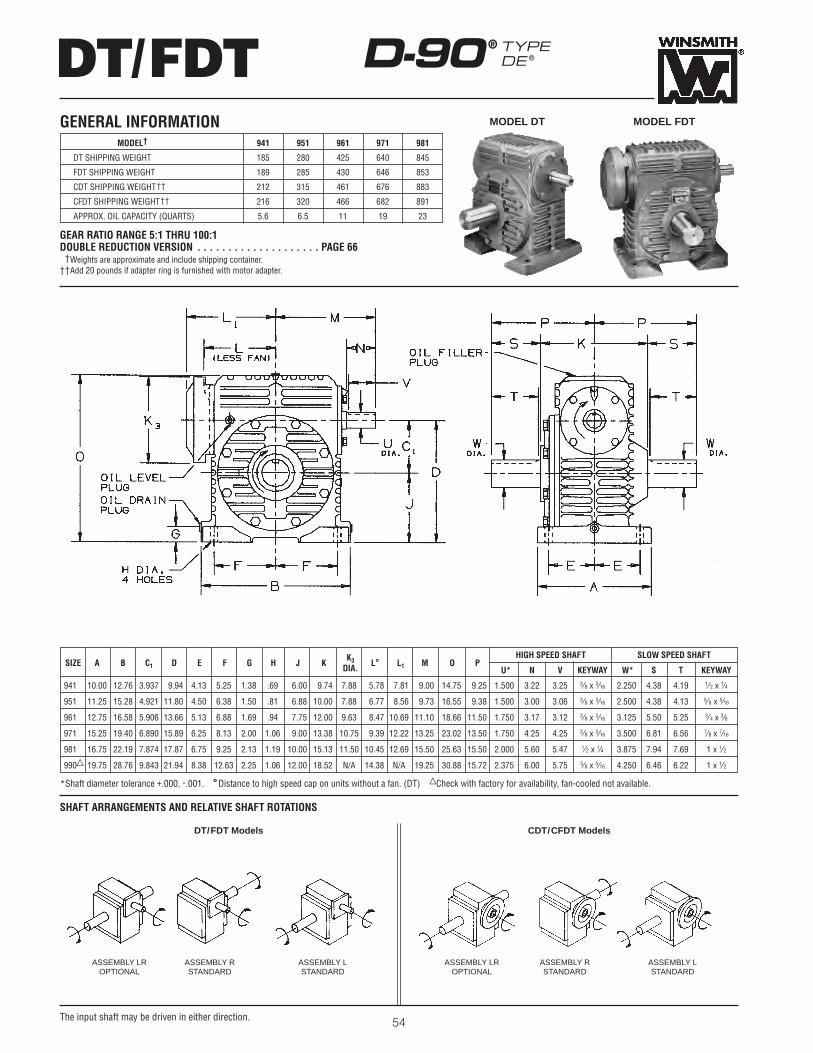
DT/FDT
54
D-90® TYPEDE®
SHAFT ARRANGEMENTS AND RELATIVE SHAFT ROTATIONS
SIZE A B C1 D E F G H J K K3 L° L1 M O PHIGH SPEED SHAFT SLOW SPEED SHAFT
DIA.
941 10.00 12.76 3.937 9.94 4.13 5.25 1.38 .69 6.00 9.74 7.88 5.78 7.81 9.00 14.75 9.25
951 11.25 15.28 4.921 11.80 4.50 6.38 1.50 .81 6.88 10.00 7.88 6.77 8.56 9.73 16.55 9.38
961 12.75 16.58 5.906 13.66 5.13 6.88 1.69 .94 7.75 12.00 9.63 8.47 10.69 11.10 18.66 11.50
971 15.25 19.40 6.890 15.89 6.25 8.13 2.00 1.06 9.00 13.38 10.75 9.39 12.22 13.25 23.02 13.50
981 16.75 22.19 7.874 17.87 6.75 9.25 2.13 1.19 10.00 15.13 11.50 10.45 12.69 15.50 25.63 15.50
990∑ 19.75 28.76 9.843 21.94 8.38 12.63 2.25 1.06 12.00 18.52 N/A 14.38 N/A 19.25 30.88 15.72
U* N V KEYWAY W* S T KEYWAY
1.500 3.22 3.25 3⁄8 x 3⁄16 2.250 4.38 4.19 1⁄ 2 x 1⁄4
1.500 3.00 3.06 3⁄8 x 3⁄16 2.500 4.38 4.13 5⁄ 8 x 5⁄16
1.750 3.17 3.12 3⁄8 x 3⁄16 3.125 5.50 5.25 3⁄ 4 x 3⁄8
1.750 4.25 4.25 3⁄8 x 3⁄16 3.500 6.81 6.56 7⁄8 x 7⁄16
2.000 5.60 5.47 1⁄2 x 1⁄4 3.875 7.94 7.69 1 x 1⁄2
2.375 6.00 5.75 5⁄8 x 5⁄16 4.250 6.46 6.22 1 x 1⁄2
*Shaft diameter tolerance +.000, -.001. °Distance to high speed cap on units without a fan. (DT) ∑Check with factory for availability, fan-cooled not available.
GENERAL INFORMATION
The input shaft may be driven in either direction.
GEAR RATIO RANGE 5:1 THRU 100:1DOUBLE REDUCTION VERSION . . . . . . . . . . . . . . . . . . . . PAGE 66††Weights are approximate and include shipping container.††Add 20 pounds if adapter ring is furnished with motor adapter.
MODEL† 941 951 961 971 981
DT SHIPPING WEIGHT 185 280 425 640 845
FDT SHIPPING WEIGHT 189 285 430 646 853
CDT SHIPPING WEIGHT†† 212 315 461 676 883
CFDT SHIPPING WEIGHT†† 216 320 466 682 891
APPROX. OIL CAPACITY (QUARTS) 5.6 6.5 11 19 23
MODEL DT MODEL FDT
DT/FDT Models CDT/CFDT Models
ASSEMBLY LROPTIONAL
ASSEMBLY RSTANDARD
ASSEMBLY LSTANDARD
ASSEMBLY LROPTIONAL
ASSEMBLY RSTANDARD
ASSEMBLY LSTANDARD

The input shaft may be driven in either direction. 55
CDT/CFDTD-90® TYPEDE®
MODEL CDT MODEL CFDT
FIG. 1 FIG. 2 FIG. 3
*Adapter ring furnished with motor adapter.
If coupling selection differs from chart, input and/or motor shaft may need alteration.
L-SERIES LOVEJOY COUPLING SELECTION VS. FRAME SIZE (Coupling not provided with unit.)
FRAMEUNIT SIZE
182TC - 184TC 213C - 215C 213TC - 215TC 254UC - 256UC 254TC - 256TC 284UC - 286UC 284TC - 286TC
941 L-110 L-110 L-110 L-110 L-150 — —
951 L-110 L-110 L-110 L-110 L-150 L-150 L-190
961 L-150 L-150 L-150 L-150 L-150 L-190 L-190
971 — L-150 L-150 L-150 L-150 L-190 L-190
981 — L-190 L-190 L-190 L-190 L-190 L-190
UNIT SIZE N.E.M.A. AB AJ AK BB BD BE BF U N V M M1 KEYWAY CONFIGURATIONSINGLE REDUCTION FRAME SIZE
182TC - 184TC 213C - 215C 5.00 7.25 8.5005 / 8.5025 .19 9.00 .50 .53 1.500 2.63 3.25 9.00 13.00 3⁄8 x 3⁄16 FIGURE 1*
941 213TC - 215TC 5.00 7.25 8.5005 / 8.5025 .19 9.00 .50 .53 1.500 2.63 3.25 9.00 13.00 3⁄8 x 3⁄16 FIGURE 1*
254TC - 256TC 254UC - 256UC 5.00 7.25 8.5005 / 8.5025 .19 9.00 1.44 .53 1.500 2.63 3.25 9.00 13.94 3⁄8 x 3⁄16 FIGURE 2*
182TC - 184TC 213C - 215C 5.00 7.25 8.5005 / 8.5025 .19 9.00 .50 .53 1.500 2.93 3.06 9.73 13.75 3⁄8 x 3⁄16 FIGURE 1*
951213TC - 215TC 5.00 7.25 8.5005 / 8.5025 .19 9.00 .50 .53 1.500 2.93 3.06 9.73 13.75 3⁄8 x 3⁄16 FIGURE 1*
254TC - 256TC 254UC - 256UC 5.00 7.25 8.5005 / 8.5025 .19 9.00 1.44 .53 1.500 2.93 3.06 9.73 14.69 3⁄8 x 3⁄16 FIGURE 2*
284TC - 286TC 284UC - 286UC 5.00 9.00 10.5005 / 10.5025 .19 11.00 .81 .53 1.500 2.93 3.06 9.73 15.44 3⁄8 x 3⁄16 FIGURE 3*
213TC - 215TC 5.00 7.25 8.5005 / 8.5025 .19 9.00 .50 .53 1.750 3.05 3.12 11.10 15.88 3⁄8 x 3⁄16 FIGURE 1*
961 254TC - 256TC 254UC - 256UC 5.00 7.25 8.5005 / 8.5025 .19 9.00 .50 .53 1.750 3.05 3.12 11.10 15.88 3⁄8 x 3⁄16 FIGURE 1*
284TC - 286TC 284UC - 286UC 5.00 9.00 10.5005 / 10.5025 .19 11.00 .25 .53 1.750 3.05 3.12 11.10 17.00 3⁄8 x 3⁄16 FIGURE 3*
213TC - 215TC 5.00 7.25 8.5005 / 8.5025 .19 9.00 .50 .53 1.750 3.77 3.63 12.63 16.88 3⁄8 x 3⁄16 FIGURE 1*
971254TC - 256TC 254UC - 256UC 5.00 7.25 8.5005 / 8.5025 .19 9.00 .50 .53 1.750 3.27 3.13 12.13 16.88 3⁄8 x 3⁄16 FIGURE 1*
284UC - 286UC 5.00 9.00 10.5005 / 10.5025 .19 11.00 .81 .53 1.750 3.77 3.63 12.63 18.56 3⁄8 x 3⁄16 FIGURE 3*
284TC - 286TC 5.00 9.00 10.5005 / 10.5025 .19 11.00 .25 .53 1.750 3.77 3.63 12.63 18.00 3⁄8 x 3⁄16 FIGURE 3*
213TC - 215TC 5.00 7.25 8.5005 / 8.5025 .19 9.00 .50 .53 2.000 3.66 3.47 13.50 17.88 1⁄2 x 1⁄4 FIGURE 1*
981254TC - 256TC 254UC - 256UC 5.00 7.25 8.5005 / 8.5025 .19 9.00 .50 .53 2.000 3.29 3.09 13.13 17.88 1⁄2 x 1⁄4 FIGURE 1*
284UC - 286UC 5.00 9.00 10.5005 / 10.5025 .19 11.00 .50 .53 2.000 3.29 3.09 13.13 19.00 1⁄2 x 1⁄4 FIGURE 3*
284TC - 286TC 5.00 9.00 10.5005 / 10.5025 .19 11.00 .50 .53 2.000 3.66 3.47 13.50 19.00 1⁄2 x 1⁄4 FIGURE 3*
*Adapter ring furnished with motor adapter.
OBSOLETEN.E.M.A.
FRAME SIZE

DV/FDV
56
D-90® TYPEDE®
SIZE A B B1 C D E F1 F2 G H J K K1 K2K3 L° L1 M ODIA.
941 10.00 15.06 6.06 3.937 5.00 4.25 8.19 4.94 1.38 .69 .25 8.88 4.94 4.81 7.88 5.78 7.81 9.00 9.87
951 11.00 17.27 6.58 4.921 5.50 4.38 9.44 5.31 1.50 .81 .25 10.88 6.00 4.88 7.88 6.77 8.56 9.73 10.50
961 13.13 19.98 7.06 5.906 6.50 5.13 11.50 5.63 1.69 .94 .25 13.00 7.06 5.18 9.63 8.47 10.69 11.10 12.50
971 15.38 23.31 8.45 6.890 7.00 6.31 13.25 6.88 2.00 1.06 .25 15.25 8.31 7.13 10.75 9.39 12.22 13.25 13.69
981 17.13 25.54 9.19 7.874 8.00 6.88 14.44 7.31 2.13 1.19 .25 17.00 9.19 7.75 11.50 10.45 12.69 15.50 15.56
P1 P2
9.25 9.25
9.38 9.38
11.50 11.50
13.50 13.50
15.50 15.50
*Shaft diameter tolerance +.000, -.001.°Distance to high speed cap on units without a fan. (DV)
SHAFT ARRANGEMENTS AND RELATIVE SHAFT ROTATIONS
GEAR RATIO RANGE 5:1 THRU 100:1DOUBLE REDUCTION VERSION . . . . . . . . . . . . . . . . . . . . PAGE 68 ††Weights are approximate and include shipping container.††Add 20 pounds if adapter ring is furnished with motor adapter.
GENERAL INFORMATIONMODEL† 941 951 961 971 981
DV SHIPPING WEIGHT 161 250 500 625 780
FDV SHIPPING WEIGHT 165 255 505 631 788
CDV SHIPPING WEIGHT†† 188 285 536 661 826
CFDV SHIPPING WEIGHT†† 192 290 541 667 834
APPROX. OIL CAPACITY (QUARTS) 2.5 4.5 8 11 13.5
MODEL DV MODEL FDV
The input shaft may be driven in either direction.
HIGH SPEED SHAFT SLOW SPEED SHAFTSIZE
U* N V KEYWAY W* S1 S2 T KEYWAY
941 1.500 3.22 3.25 3⁄8 x 3⁄16 2.250 4.38 4.25 4.19 1⁄2 x 1⁄4
951 1.500 3.00 3.06 3⁄8 x 3⁄16 2.500 4.38 3.88 4.13 5⁄8 x 5⁄16
961 1.750 3.17 3.12 3⁄8 x 3⁄16 3.125 5.50 5.00 5.25 3⁄4 x 3⁄8
971 1.750 4.25 4.25 3⁄8 x 3⁄16 3.500 6.81 6.50 6.56 7⁄8 x 7⁄16
981 2.000 5.60 5.47 1⁄2 x 1⁄4 3.875 7.94 7.50 7.69 1 x 1⁄2
DV/FDV Models CDV/CFDV Models
ASSEMBLY RUSTANDARD
ASSEMBLY LUSTANDARD
ASSEMBLY RDSTANDARD
ASSEMBLY LDSTANDARD
ASSEMBLY RUSTANDARD
ASSEMBLY LUSTANDARD
ASSEMBLY RDSTANDARD
ASSEMBLY LDSTANDARD
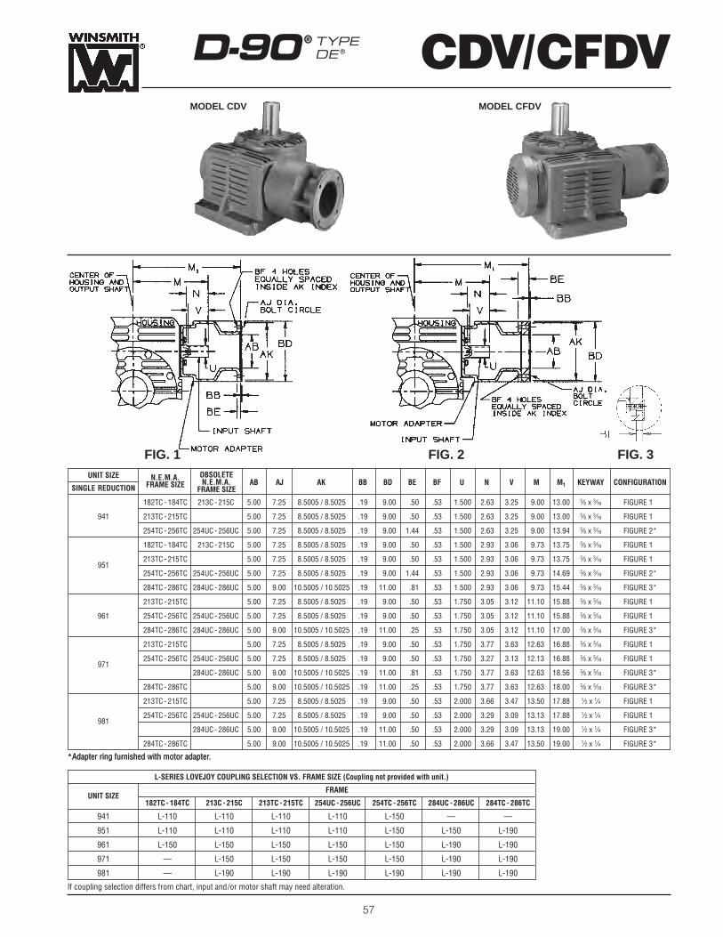
The input shaft may be driven in either direction. 57
CDV/CFDVD-90® TYPEDE®
MODEL CDV MODEL CFDV
FIG. 1 FIG. 2 FIG. 3
*Adapter ring furnished with motor adapter.
If coupling selection differs from chart, input and/or motor shaft may need alteration.
L-SERIES LOVEJOY COUPLING SELECTION VS. FRAME SIZE (Coupling not provided with unit.)
FRAMEUNIT SIZE
182TC - 184TC 213C - 215C 213TC - 215TC 254UC - 256UC 254TC - 256TC 284UC - 286UC 284TC - 286TC
941 L-110 L-110 L-110 L-110 L-150 — —
951 L-110 L-110 L-110 L-110 L-150 L-150 L-190
961 L-150 L-150 L-150 L-150 L-150 L-190 L-190
971 — L-150 L-150 L-150 L-150 L-190 L-190
981 — L-190 L-190 L-190 L-190 L-190 L-190
UNIT SIZE N.E.M.A. AB AJ AK BB BD BE BF U N V M M1 KEYWAY CONFIGURATIONSINGLE REDUCTION FRAME SIZE
182TC - 184TC 213C - 215C 5.00 7.25 8.5005 / 8.5025 .19 9.00 .50 .53 1.500 2.63 3.25 9.00 13.00 3⁄8 x 3⁄16 FIGURE 1*
941 213TC - 215TC 5.00 7.25 8.5005 / 8.5025 .19 9.00 .50 .53 1.500 2.63 3.25 9.00 13.00 3⁄8 x 3⁄16 FIGURE 1*
254TC - 256TC 254UC - 256UC 5.00 7.25 8.5005 / 8.5025 .19 9.00 1.44 .53 1.500 2.63 3.25 9.00 13.94 3⁄8 x 3⁄16 FIGURE 2*
182TC - 184TC 213C - 215C 5.00 7.25 8.5005 / 8.5025 .19 9.00 .50 .53 1.500 2.93 3.06 9.73 13.75 3⁄8 x 3⁄16 FIGURE 1*
951213TC - 215TC 5.00 7.25 8.5005 / 8.5025 .19 9.00 .50 .53 1.500 2.93 3.06 9.73 13.75 3⁄8 x 3⁄16 FIGURE 1*
254TC - 256TC 254UC - 256UC 5.00 7.25 8.5005 / 8.5025 .19 9.00 1.44 .53 1.500 2.93 3.06 9.73 14.69 3⁄8 x 3⁄16 FIGURE 2*
284TC - 286TC 284UC - 286UC 5.00 9.00 10.5005 / 10.5025 .19 11.00 .81 .53 1.500 2.93 3.06 9.73 15.44 3⁄8 x 3⁄16 FIGURE 3*
213TC - 215TC 5.00 7.25 8.5005 / 8.5025 .19 9.00 .50 .53 1.750 3.05 3.12 11.10 15.88 3⁄8 x 3⁄16 FIGURE 1*
961 254TC - 256TC 254UC - 256UC 5.00 7.25 8.5005 / 8.5025 .19 9.00 .50 .53 1.750 3.05 3.12 11.10 15.88 3⁄8 x 3⁄16 FIGURE 1*
284TC - 286TC 284UC - 286UC 5.00 9.00 10.5005 / 10.5025 .19 11.00 .25 .53 1.750 3.05 3.12 11.10 17.00 3⁄8 x 3⁄16 FIGURE 3*
213TC - 215TC 5.00 7.25 8.5005 / 8.5025 .19 9.00 .50 .53 1.750 3.77 3.63 12.63 16.88 3⁄8 x 3⁄16 FIGURE 1*
971254TC - 256TC 254UC - 256UC 5.00 7.25 8.5005 / 8.5025 .19 9.00 .50 .53 1.750 3.27 3.13 12.13 16.88 3⁄8 x 3⁄16 FIGURE 1*
284UC - 286UC 5.00 9.00 10.5005 / 10.5025 .19 11.00 .81 .53 1.750 3.77 3.63 12.63 18.56 3⁄8 x 3⁄16 FIGURE 3*
284TC - 286TC 5.00 9.00 10.5005 / 10.5025 .19 11.00 .25 .53 1.750 3.77 3.63 12.63 18.00 3⁄8 x 3⁄16 FIGURE 3*
213TC - 215TC 5.00 7.25 8.5005 / 8.5025 .19 9.00 .50 .53 2.000 3.66 3.47 13.50 17.88 1⁄2 x 1⁄4 FIGURE 1*
981254TC - 256TC 254UC - 256UC 5.00 7.25 8.5005 / 8.5025 .19 9.00 .50 .53 2.000 3.29 3.09 13.13 17.88 1⁄2 x 1⁄4 FIGURE 1*
284UC - 286UC 5.00 9.00 10.5005 / 10.5025 .19 11.00 .50 .53 2.000 3.29 3.09 13.13 19.00 1⁄2 x 1⁄4 FIGURE 3*
284TC - 286TC 5.00 9.00 10.5005 / 10.5025 .19 11.00 .50 .53 2.000 3.66 3.47 13.50 19.00 1⁄2 x 1⁄4 FIGURE 3*
*Adapter ring furnished with motor adapter.
OBSOLETEN.E.M.A.
FRAME SIZE

DSF/FDSF
58
D-90® TYPEDE®
SIZE A B B1 C1 D E F1 F2 G H K K1K3 L° L1 M O P1 P2DIA.
941 10.00 15.06 6.06 3.937 8.88 4.25 8.19 4.94 1.38 .69 4.44 4.94 7.88 5.78 7.81 9.00 13.69 4.25 4.25
951 11.00 17.27 6.58 4.921 10.92 4.38 9.44 5.31 1.50 .81 4.81 6.00 7.88 6.77 8.56 9.73 15.80 5.06 5.06
961 13.13 19.98 7.06 5.906 12.97 5.13 11.50 5.63 1.69 .94 5.70 7.06 9.63 8.47 10.69 11.10 18.15 5.31 5.31
971 15.38 23.31 8.45 6.890 15.20 6.31 13.25 6.88 2.00 1.06 6.56 8.31 10.75 9.39 12.22 13.25 22.33 6.69 6.69
981 17.13 25.54 9.19 7.874 17.06 6.88 14.44 7.31 2.13 1.19 6.88 9.19 11.50 10.45 12.69 15.50 24.82 6.30 6.30
• Shaft diameter tolerance +.000, -.001.�Bore tolerance +.000, +.002.° Distance to high speed cap on units without a fan. (DSF)N Check with factory for other bore sizes.
Y Y1 Z
5.00 .75 4.13
5.50 .44 4.88
6.50 1.19 5.75
7.00 .31 6.75
8.00 1.70 6.75
SHAFT ARRANGEMENTS AND RELATIVE SHAFT ROTATIONS
GEAR RATIO RANGE 5:1 THRU 100:1DOUBLE REDUCTION VERSION . . . . . . . . . . . . . . . . . . . . PAGE 70††Weights are approximate and include shipping container.††Add 20 pounds if adapter ring is furnished with motor adapter.
MODEL† 941 951 961 971 981
DSF SHIPPING WEIGHT 171 255 350 560 750
FDSF SHIPPING WEIGHT 175 260 355 566 758
CFDSF SHIPPING WEIGHT†† 202 290 386 596 788
CDSF SHIPPING WEIGHT†† 198 295 391 602 796
APPROX. OIL CAPACITY (QUARTS) 5.3 4 7.5 12 15
MODEL DSF MODEL FDSF
The input shaft may be driven in either direction.
HIGH SPEED SHAFT SLOW SPEED SHAFT BORESN
SIZEU• N V KEYWAY W� KEYWAY W� KEYWAY
941 1.500 3.22 3.25 3⁄8 x 3⁄16 27⁄16 5⁄8 x 5⁄16 215⁄16 5⁄8 x 5⁄16
951 1.500 3.00 3.06 3⁄8 x 3⁄16 25⁄8 5⁄8 x 5⁄16 37⁄16 7⁄8 x 7⁄16
961 1.750 3.17 3.12 3⁄8 x 3⁄16 3 3⁄4 x 3⁄8 315⁄16 1 x 3⁄8
971 1.750 4.25 4.25 3⁄8 x 3⁄16 31⁄4 3⁄4 x 3⁄8 47⁄16 1 x 1⁄2
981 2.000 5.60 5.47 1⁄2 x 1⁄4 33⁄4 7⁄8 x 7⁄16 47⁄16 1 x 1⁄2
DSF/FDSF Models CDSF/CFDSF Models
ASSEMBLY DRSTANDARD
CUSTOMER’S MACHINE
ASSEMBLY DLSTANDARD
ASSEMBLY DRSTANDARD
CUSTOMER’S MACHINE
ASSEMBLY DLSTANDARD
GENERAL INFORMATION

The input shaft may be driven in either direction. 59
CDSF/CFDSFD-90® TYPEDE®
MODEL CDSF MODEL CFDSF
FIG. 1 FIG. 2 FIG. 3
*Adapter ring furnished with motor adapter.
If coupling selection differs from chart, input and/or motor shaft may need alteration.
L-SERIES LOVEJOY COUPLING SELECTION VS. FRAME SIZE (Coupling not provided with unit.)
FRAMEUNIT SIZE
182TC - 184TC 213C - 215C 213TC - 215TC 254UC - 256UC 254TC - 256TC 284UC - 286UC 284TC - 286TC
941 L-110 L-110 L-110 L-110 L-150 — —
951 L-110 L-110 L-110 L-110 L-150 L-150 L-190
961 L-150 L-150 L-150 L-150 L-150 L-190 L-190
971 — L-150 L-150 L-150 L-150 L-190 L-190
981 — L-190 L-190 L-190 L-190 L-190 L-190
UNIT SIZE N.E.M.A. AB AJ AK BB BD BE BF U N V M M1 KEYWAY CONFIGURATIONSINGLE REDUCTION FRAME SIZE
182TC - 184TC 213C - 215C 5.00 7.25 8.5005 / 8.5025 .19 9.00 .50 .53 1.500 2.63 3.25 9.00 13.00 3⁄8 x 3⁄16 FIGURE 1*
941 213TC - 215TC 5.00 7.25 8.5005 / 8.5025 .19 9.00 .50 .53 1.500 2.63 3.25 9.00 13.00 3⁄8 x 3⁄16 FIGURE 1*
254TC - 256TC 254UC - 256UC 5.00 7.25 8.5005 / 8.5025 .19 9.00 1.44 .53 1.500 2.63 3.25 9.00 13.94 3⁄8 x 3⁄16 FIGURE 2*
182TC - 184TC 213C - 215C 5.00 7.25 8.5005 / 8.5025 .19 9.00 .50 .53 1.500 2.93 3.06 9.73 13.75 3⁄8 x 3⁄16 FIGURE 1*
951213TC - 215TC 5.00 7.25 8.5005 / 8.5025 .19 9.00 .50 .53 1.500 2.93 3.06 9.73 13.75 3⁄8 x 3⁄16 FIGURE 1*
254TC - 256TC 254UC - 256UC 5.00 7.25 8.5005 / 8.5025 .19 9.00 1.44 .53 1.500 2.93 3.06 9.73 14.69 3⁄8 x 3⁄16 FIGURE 2*
284TC - 286TC 284UC - 286UC 5.00 9.00 10.5005 / 10.5025 .19 11.00 .81 .53 1.500 2.93 3.06 9.73 15.44 3⁄8 x 3⁄16 FIGURE 3*
213TC - 215TC 5.00 7.25 8.5005 / 8.5025 .19 9.00 .50 .53 1.750 3.05 3.12 11.10 15.88 3⁄8 x 3⁄16 FIGURE 1*
961 254TC - 256TC 254UC - 256UC 5.00 7.25 8.5005 / 8.5025 .19 9.00 .50 .53 1.750 3.05 3.12 11.10 15.88 3⁄8 x 3⁄16 FIGURE 1*
284TC - 286TC 284UC - 286UC 5.00 9.00 10.5005 / 10.5025 .19 11.00 .25 .53 1.750 3.05 3.12 11.10 17.00 3⁄8 x 3⁄16 FIGURE 3*
213TC - 215TC 5.00 7.25 8.5005 / 8.5025 .19 9.00 .50 .53 1.750 3.77 3.63 12.63 16.88 3⁄8 x 3⁄16 FIGURE 1*
971254TC - 256TC 254UC - 256UC 5.00 7.25 8.5005 / 8.5025 .19 9.00 .50 .53 1.750 3.27 3.13 12.13 16.88 3⁄8 x 3⁄16 FIGURE 1*
284UC - 286UC 5.00 9.00 10.5005 / 10.5025 .19 11.00 .81 .53 1.750 3.77 3.63 12.63 18.56 3⁄8 x 3⁄16 FIGURE 3*
284TC - 286TC 5.00 9.00 10.5005 / 10.5025 .19 11.00 .25 .53 1.750 3.77 3.63 12.63 18.00 3⁄8 x 3⁄16 FIGURE 3*
213TC - 215TC 5.00 7.25 8.5005 / 8.5025 .19 9.00 .50 .53 2.000 3.66 3.47 13.50 17.88 1⁄2 x 1⁄4 FIGURE 1*
981254TC - 256TC 254UC - 256UC 5.00 7.25 8.5005 / 8.5025 .19 9.00 .50 .53 2.000 3.29 3.09 13.13 17.88 1⁄2 x 1⁄4 FIGURE 1*
284UC - 286UC 5.00 9.00 10.5005 / 10.5025 .19 11.00 .50 .53 2.000 3.29 3.09 13.13 19.00 1⁄2 x 1⁄4 FIGURE 3*
284TC - 286TC 5.00 9.00 10.5005 / 10.5025 .19 11.00 .50 .53 2.000 3.66 3.47 13.50 19.00 1⁄2 x 1⁄4 FIGURE 3*
*Adapter ring furnished with motor adapter.
OBSOLETEN.E.M.A.
FRAME SIZE

P2 Q1 S X Y Y1 Z
4.25 12.94 2.13 1.63 2.25 1.44 4.13
5.06 14.30 2.06 1.94 2.88 1.94 4.88
5.31 16.41 2.69 2.38 3.25 2.19 5.75
6.69 20.02 2.69 2.38 3.88 2.44 6.75
6.30 23.00 2.69 2.38 4.25 2.63 6.75
DSR/FDSR
60
• Shaft diameter tolerance +.000, -.001.�Bore tolerance +.000, +.002.° Distance to high speed cap on units without a fan. (DSF)N Check with factory for other bore sizes.
SHAFT ARRANGEMENTS AND RELATIVE SHAFT ROTATIONS
D-90® TYPEDE®
SIZE BB B1 C1 D E F G H IMAX IMIN J K K3 KK L° L1 M O P1DIA.
941 12.76 13.94 3.937 9.69 3.50 4.75 .56 .53 29.00 21.00 5.75 4.44 7.88 4.00 5.78 7.81 9.00 15.69 4.25
951 15.29 15.43 4.921 10.67 5.00 6.75 .75 .81 31.00 22.00 5.75 4.81 7.88 4.81 6.77 8.56 9.73 17.56 5.06
961 16.58 17.66 5.906 12.16 5.75 7.75 .88 .94 37.50 26.50 6.25 5.70 9.63 5.06 8.47 10.69 11.10 19.91 5.31
971 19.40 21.27 6.890 14.77 5.75 7.75 .88 .94 37.50 26.50 7.88 6.56 10.75 6.44 9.39 12.22 13.25 23.88 6.69
981 22.19 24.25 7.874 16.37 5.75 7.75 .88 .94 37.50 26.50 8.50 6.88 11.50 6.13 10.45 12.69 15.50 26.50 6.30
GEAR RATIO RANGE 5:1 THRU 100:1DOUBLE REDUCTION VERSION . . . . . . . . . . . . . . . . . . . . PAGE 72††Weights are approximate and include shipping container.††Add 20 pounds if adapter ring is furnished with motor adapter.
GENERAL INFORMATIONMODEL† 941 951 961 971 981
DSR SHIPPING WEIGHT 207 320 440 700 900
FDSR SHIPPING WEIGHT 211 325 445 706 908
CFDSR SHIPPING WEIGHT†† 238 355 476 736 938
CDSR SHIPPING WEIGHT†† 234 360 481 742 946
APPROX. OIL CAPACITY (QUARTS) 2.1 2.5 3.5 8 10
MODEL DSR MODEL FDSR
The input shaft may be driven in either direction.
ASSEMBLY DRSTANDARD
ASSEMBLY DLSTANDARD
ASSEMBLY DRSTANDARD
ASSEMBLY DLSTANDARD
DSR /FDSR Models CDSR/CFDSR Models
HIGH SPEED SHAFT SLOW SPEED SHAFT BORESN
SIZEU• N V KEYWAY W� KEYWAY W� KEYWAY
941 1.500 3.22 3.25 3⁄8 x 3⁄16 27⁄16 5⁄8 x 5⁄16 215⁄16 5⁄8 x 5⁄16
951 1.500 3.00 3.06 3⁄8 x 3⁄16 25⁄8 5⁄8 x 5⁄16 37⁄16 7⁄8 x 7⁄16
961 1.750 3.17 3.12 3⁄8 x 3⁄16 3 3⁄4 x 3⁄8 315⁄16 1 x 3⁄8
971 1.750 4.25 4.25 3⁄8 x 3⁄16 31⁄4 3⁄4 x 3⁄8 47⁄16 1 x 1⁄2
981 2.000 5.60 5.47 1⁄2 x 1⁄4 33⁄4 7⁄8 x 7⁄16 47⁄16 1 x 1⁄2

The input shaft may be driven in either direction. 61
CDSR/CFDSRD-90® TYPEDE®
MODEL CDSR MODEL CFDSR
FIG. 1 FIG. 2 FIG. 3
*Adapter ring furnished with motor adapter.
If coupling selection differs from chart, input and/or motor shaft may need alteration.
L-SERIES LOVEJOY COUPLING SELECTION VS. FRAME SIZE (Coupling not provided with unit.)
FRAMEUNIT SIZE
182TC - 184TC 213C - 215C 213TC - 215TC 254UC - 256UC 254TC - 256TC 284UC - 286UC 284TC - 286TC
941 L-110 L-110 L-110 L-110 L-150 — —
951 L-110 L-110 L-110 L-110 L-150 L-150 L-190
961 L-150 L-150 L-150 L-150 L-150 L-190 L-190
971 — L-150 L-150 L-150 L-150 L-190 L-190
981 — L-190 L-190 L-190 L-190 L-190 L-190
UNIT SIZE N.E.M.A. AB AJ AK BB BD BE BF U N V M M1 KEYWAY CONFIGURATIONSINGLE REDUCTION FRAME SIZE
182TC - 184TC 213C - 215C 5.00 7.25 8.5005 / 8.5025 .19 9.00 .50 .53 1.500 2.63 3.25 9.00 13.00 3⁄8 x 3⁄16 FIGURE 1*
941 213TC - 215TC 5.00 7.25 8.5005 / 8.5025 .19 9.00 .50 .53 1.500 2.63 3.25 9.00 13.00 3⁄8 x 3⁄16 FIGURE 1*
254TC - 256TC 254UC - 256UC 5.00 7.25 8.5005 / 8.5025 .19 9.00 1.44 .53 1.500 2.63 3.25 9.00 13.94 3⁄8 x 3⁄16 FIGURE 2*
182TC - 184TC 213C - 215C 5.00 7.25 8.5005 / 8.5025 .19 9.00 .50 .53 1.500 2.93 3.06 9.73 13.75 3⁄8 x 3⁄16 FIGURE 1*
951213TC - 215TC 5.00 7.25 8.5005 / 8.5025 .19 9.00 .50 .53 1.500 2.93 3.06 9.73 13.75 3⁄8 x 3⁄16 FIGURE 1*
254TC - 256TC 254UC - 256UC 5.00 7.25 8.5005 / 8.5025 .19 9.00 1.44 .53 1.500 2.93 3.06 9.73 14.69 3⁄8 x 3⁄16 FIGURE 2*
284TC - 286TC 284UC - 286UC 5.00 9.00 10.5005 / 10.5025 .19 11.00 .81 .53 1.500 2.93 3.06 9.73 15.44 3⁄8 x 3⁄16 FIGURE 3*
213TC - 215TC 5.00 7.25 8.5005 / 8.5025 .19 9.00 .50 .53 1.750 3.05 3.12 11.10 15.88 3⁄8 x 3⁄16 FIGURE 1*
961 254TC - 256TC 254UC - 256UC 5.00 7.25 8.5005 / 8.5025 .19 9.00 .50 .53 1.750 3.05 3.12 11.10 15.88 3⁄8 x 3⁄16 FIGURE 1*
284TC - 286TC 284UC - 286UC 5.00 9.00 10.5005 / 10.5025 .19 11.00 .25 .53 1.750 3.05 3.12 11.10 17.00 3⁄8 x 3⁄16 FIGURE 3*
213TC - 215TC 5.00 7.25 8.5005 / 8.5025 .19 9.00 .50 .53 1.750 3.77 3.63 12.63 16.88 3⁄8 x 3⁄16 FIGURE 1*
971254TC - 256TC 254UC - 256UC 5.00 7.25 8.5005 / 8.5025 .19 9.00 .50 .53 1.750 3.27 3.13 12.13 16.88 3⁄8 x 3⁄16 FIGURE 1*
284UC - 286UC 5.00 9.00 10.5005 / 10.5025 .19 11.00 .81 .53 1.750 3.77 3.63 12.63 18.56 3⁄8 x 3⁄16 FIGURE 3*
284TC - 286TC 5.00 9.00 10.5005 / 10.5025 .19 11.00 .25 .53 1.750 3.77 3.63 12.63 18.00 3⁄8 x 3⁄16 FIGURE 3*
213TC - 215TC 5.00 7.25 8.5005 / 8.5025 .19 9.00 .50 .53 2.000 3.66 3.47 13.50 17.88 1⁄2 x 1⁄4 FIGURE 1*
981254TC - 256TC 254UC - 256UC 5.00 7.25 8.5005 / 8.5025 .19 9.00 .50 .53 2.000 3.29 3.09 13.13 17.88 1⁄2 x 1⁄4 FIGURE 1*
284UC - 286UC 5.00 9.00 10.5005 / 10.5025 .19 11.00 .50 .53 2.000 3.29 3.09 13.13 19.00 1⁄2 x 1⁄4 FIGURE 3*
284TC - 286TC 5.00 9.00 10.5005 / 10.5025 .19 11.00 .50 .53 2.000 3.66 3.47 13.50 19.00 1⁄2 x 1⁄4 FIGURE 3*
*Adapter ring furnished with motor adapter.
OBSOLETEN.E.M.A.
FRAME SIZE

DL/FDL
62
D-90® TYPEDE®
*Shaft diameter tolerance +.000, -.001.°Distance to high speed cap on units without a fan. (DL)
∑For information on sizes 941, 971 and 981, contact the factory.
SHAFT ARRANGEMENTS AND RELATIVE SHAFT ROTATIONS
SIZE∑ A C1 D E G H J K K1 K2K3 L° L1 M O P
Y DIMENSIONSDIA. TAP DEPTH
951 17.50 4.921 8.00 7.63 1.50 .81 .25 8.11 6.88 4.75 7.88 6.77 8.56 9.73 13.63 23.50 3⁄8 - 16 1.00 2.00
961 19.38 5.906 9.50 8.44 1.75 .94 .38 9.06 7.75 5.00 9.63 8.47 10.69 11.10 15.88 26.00 5⁄8 - 11 1.50 2.25
BOLTCIRCLE
GEAR RATIO RANGE 5:1 THRU 100:1DOUBLE REDUCTION VERSION . . . . . . . . . . . . . . . . . . . . PAGE 74††Weights are approximate and include shipping container.††Add 20 pounds if adapter ring is furnished with motor adapter.
GENERAL INFORMATIONMODEL† 951 961
DL SHIPPING WEIGHT 470 650
FDL SHIPPING WEIGHT 475 655
CFDL SHIPPING WEIGHT†† 505 686
CDL SHIPPING WEIGHT†† 510 691
APPROX. OIL CAPACITY (QUARTS) 8 14
MODEL DL MODEL FDL
The input shaft may be driven in either direction.
HIGH SPEED SHAFT SLOW SPEED SHAFTSIZE
U* N V KEYWAY W* S S2 T KEYWAY
951 1.500 3.00 3.06 3⁄8 x 3⁄16 2.938 7.81 15.50 7.56 3⁄4 x 3⁄8
961 1.750 3.17 3.12 3⁄8 x 3⁄16 3.500 8.80 16.50 8.75 7⁄8 x 7⁄16
DL /FDL Models CDL /CFDL Models
ASSEMBLY RDSTANDARD
ASSEMBLY LDSTANDARD
ASSEMBLY RDSTANDARD
ASSEMBLY LDSTANDARD

The input shaft may be driven in either direction.
CDL/CFDLD-90® TYPEDE®
UNIT SIZE N.E.M.A. AB AJ AK BB BD BE BF U N V M M1 KEYWAY CONFIGURATIONSINGLE REDUCTION FRAME SIZE
182TC - 184TC 213C - 215C 5.00 7.25 8.5005 / 8.5025 .19 9.00 .50 .53 1.500 2.93 3.06 9.73 13.75 3⁄8 x 3⁄16 FIGURE 1*
951213TC - 215TC 5.00 7.25 8.5005 / 8.5025 .19 9.00 .50 .53 1.500 2.93 3.06 9.73 13.75 3⁄8 x 3⁄16 FIGURE 1*
254TC - 256TC 254UC - 256UC 5.00 7.25 8.5005 / 8.5025 .19 9.00 1.44 .53 1.500 2.93 3.06 9.73 14.69 3⁄8 x 3⁄16 FIGURE 2*
284TC - 286TC 284UC - 286UC 5.00 9.00 10.5005 / 10.5025 .19 11.00 .81 .53 1.500 2.93 3.06 9.73 15.44 3⁄8 x 3⁄16 FIGURE 3*
213TC - 215TC 5.00 7.25 8.5005 / 8.5025 .19 9.00 .50 .53 1.750 3.05 3.12 11.10 15.88 3⁄8 x 3⁄16 FIGURE 1*
961 254TC - 256TC 254UC - 256UC 5.00 7.25 8.5005 / 8.5025 .19 9.00 .50 .53 1.750 3.05 3.12 11.10 15.88 3⁄8 x 3⁄16 FIGURE 1*
284TC - 286TC 284UC - 286UC 5.00 9.00 10.5005 / 10.5025 .19 11.00 .25 .53 1.750 3.05 3.12 11.10 17.00 3⁄8 x 3⁄16 FIGURE 3*
*Adapter ring furnished with motor adapter.
If coupling selection differs from chart, input and/or motor shaft may need alteration.
L-SERIES LOVEJOY COUPLING SELECTION VS. FRAME SIZE (Coupling not provided with unit.)
FRAMEUNIT SIZE
182TC - 184TC 213C - 215C 213TC - 215TC 254UC - 256UC 254TC - 256TC 284UC - 286UC 284TC - 286TC
951 L-110 L-110 L-110 L-110 L-150 L-150 L-190
961 L-150 L-150 L-150 L-150 L-150 L-190 L-190
MODEL CDL MODEL CFDL
63
FIG. 1 FIG. 2
FIG. 3OBSOLETEN.E.M.A.
FRAME SIZE

ASSEMBLY LSTANDARD
ASSEMBLY RSTANDARD
64The input shaft may be driven in either direction.
DBD
††L3 dimension equals 5.46 on MDBD models.††L3 dimension equals 6.28 on MDBD models.*Shaft diameter tolerance +.000, -.001.
SHAFT ARRANGEMENTS AND RELATIVE SHAFT ROTATIONS
D-90® TYPEDE®
SIZE A B C1 C2 D E F G H J K L1 L2 L3 M O O1 P R
941 10.00 12.76 3.937 2.625 5.75 4.13 5.25 1.38 .69 9.69 9.74 5.78 10.90 4.50†† 6.50 15.69 11.31 9.25 8.44
951 11.25 15.29 4.921 2.625 5.75 4.50 6.38 1.50 .81 10.67 10.00 6.77 11.59 4.50†† 6.50 17.56 11.31 9.38 9.13
961 12.75 16.58 5.906 3.000 6.25 5.13 6.88 1.69 .94 12.16 12.00 8.47 13.26 4.63†† 7.00 19.91 12.63 11.50 10.44
971 15.25 19.40 6.890 3.500 7.88 6.25 8.13 2.00 1.06 14.77 13.38 9.39 15.45 5.06†† 7.38 23.88 14.92 13.50 12.63
981 16.75 22.19 7.874 4.250 8.50 6.75 9.25 2.13 1.19 16.37 15.13 10.45 17.54 5.88†† 8.19 26.50 15.63 15.50 14.63
GEAR RATIO RANGE 100:1 THRU 10,000:1SINGLE REDUCTION VERSION . . . . . . . . . . . . . . . . . . . . PAGE 52††Weights are approximate and include shipping container.††Weights given for 56C-145TC, for larger frames add 5 pounds.
GENERAL INFORMATIONMODEL† 941 951 961 971 981
DBD SHIPPING WEIGHT 217 323 490 740 990
CDBD SHIPPING WEIGHT†† 226 327 494 750 995
MDBD SHIPPING WEIGHT†† 221 332 500 744 1000
APPROX. OIL CAPACITY (QUARTS) 2.7 3.5 4.5 9 12
MODEL DBD
The input shaft may be driven in either direction.
HIGH SPEED SHAFT SLOW SPEED SHAFTSIZE
U* N V KEYWAY W* S T KEYWAY
941 1.000 2.75 2.38 .25 x .13 2.250 4.38 4.19 .50 x .25
951 1.000 2.75 2.38 .25 x .13 2.500 4.38 4.13 .63 x .31
961 1.000 3.06 2.38 .25 x .13 3.125 5.50 5.25 .75 x .38
971 1.000 2.31 2.50 .25 x .13 3.500 6.81 6.56 .88 x .44
981 1.250 2.31 2.50 .25 x .13 3.875 7.94 7.69 1.00 x .50
NOTE:To identify double reduction unit assemblies, first list the letters designating the primary (smaller) housing shaftarrangements followed by a hyphen. After the hyphen, listthe letter(s) designating the secondary (larger) housingshaft arrangements. These combined arrangements describethe double reduction assembly. (See examples below)
ASSEMBLY RSTANDARD
ASSEMBLY LROPTIONAL
ASSEMBLY LSTANDARD
ASSEMBLY LU-L
LULU
RULD
RU
RD ASSEMBLY LU-L
ASSEMBLY LROPTIONAL

CDBD/MDBDD-90® TYPEDE®
MODEL CDBD MODEL MDBD
65
QUILL STYLEFRAME MOTOR ADAPTER
SIZE SIZE M1 M1 M1RANGE 56C 182TC 213TC145TC 184TC 215TC
941 56C-184TC 5.38 5.38 NA
951 56C-184TC 5.38 5.38 NA
961 56C-184TC 5.56 5.56 NA
971 56C-184TC 5.81 5.81 NA
981 56C-215TC 6.63 6.63 6.63
L-SERIES LOVEJOY COUPLING SELECTION VS. FRAME SIZE (Coupling not provided with unit.)
FRAMEUNIT SIZE
56C 143TC-145TC 182TC-184TC 213TC-215TC
941 L-090 L-095 L-100 —
951 L-090 L-095 L-100 —
961 L-090 L-095 L-100 —
971 L-090 L-095 L-100 —
981 L-100 L-100 L-100 L-150
COUPLING STYLE MOTOR ADAPTER
56C-145TC 182TC-184TC 213TC-215TC**
AB M3 BE1 AB M3 BE1 AB M3 BE1M2 U1* KEYWAY
4.13 9.13 .38 4.25 10.19 .50 NA 6.50 1.000 .25 x .13
4.13 9.13 .38 4.25 10.19 .50 NA 6.50 1.000 .25 x .13
4.13 9.75 .38 4.75 10.88 .50 NA 7.00 1.000 .25 x .13
4.13 10.00 .38 4.75 11.13 .50 NA 7.38 1.000 .25 x .13
4.13 10.81 .38 4.75 11.94 .50 4.75 12.88 1.44 8.19 1.250 .25 x .13
FRAME 143TC 182TC 213TCNO. 56C 145TC 184TC 215TC
AJ 5.88 5.88 7.25 7.25
AK 4.50 4.50 8.50 8.50
BB .19 .19 .19 .19
BD 6.50 6.50 9.00 9.00
BD1 6.63 6.63 9.00 9.00
BE .31 .31 .38 .38
BF .406 .406 .531 .531
KEYWAY .19 x .09 .25 x .13 .31 x .16
Bore+.001 .6255 .8755 1.1255 1.3755-.000
**Shaft diameter tolerance +.000, -.001.**Adapter ring furnished with motor adapter.
If coupling selection differs from chart, input and/or motor shaft may need alteration.
The input shaft may be driven in either direction.
56C-145TC
182TC-184TC213TC-215TC
213TC-215TC**182TC-184TC
56C-145TC

66
††L3 dimension equals 5.46 on MDTD models.††L3 dimension equals 6.28 on MDTD models.*Shaft diameter tolerance +.000, -.001.
SHAFT ARRANGEMENTS AND RELATIVE SHAFT ROTATIONS
SIZE A B C1 C2 D E F G H J K L1 L2 L3 M O O1 P R
941 10.00 12.76 3.937 2.625 9.94 4.13 5.25 1.38 .69 6.00 9.74 5.78 10.90 4.50†† 6.50 14.75 15.50 9.25 8.44
951 11.25 15.28 4.921 2.625 11.80 4.50 6.38 1.50 .81 6.88 10.00 6.77 11.59 4.50†† 6.50 16.55 17.36 9.38 9.13
961 12.75 16.58 5.906 3.000 13.66 5.13 6.88 1.69 .94 7.75 12.00 8.47 13.26 4.63†† 7.00 18.66 20.04 11.50 10.44
971 15.25 19.40 6.890 3.500 15.89 6.25 8.13 2.00 1.06 9.00 13.38 9.39 15.45 5.06†† 7.38 23.02 22.93 13.50 12.63
981 16.75 22.19 7.874 4.250 17.87 6.75 9.25 2.13 1.19 10.00 15.13 10.45 17.54 5.88†† 8.19 25.63 25.00 15.50 14.63
GEAR RATIO RANGE 100:1 THRU 10,000:1SINGLE REDUCTION VERSION . . . . . . . . . . . . . . . . . . . . PAGE 54††Weights are approximate and include shipping container.††Weights given for 56C-145TC, for larger frames add 5 pounds.
MODEL† 941 951 961 971 981
DTD SHIPPING WEIGHT 223 318 475 720 975
CDTD SHIPPING WEIGHT†† 232 322 479 730 980
MDTD SHIPPING WEIGHT†† 227 327 485 724 985
APPROX. OIL CAPACITY (QUARTS) 6.2 7.5 12 20 25
GENERAL INFORMATION MODEL DTD
The input shaft may be driven in either direction.
HIGH SPEED SHAFT SLOW SPEED SHAFTSIZE
U* N V KEYWAY W* S T KEYWAY
941 1.000 2.75 2.38 .25 x .13 2.250 4.38 4.19 .50 x .25
951 1.000 2.75 2.38 .25 x .13 2.500 4.38 4.13 .63 x .31
961 1.000 3.06 2.38 .25 x .13 3.125 5.50 5.25 .75 x .38
971 1.000 2.31 2.50 .25 x .13 3.500 6.81 6.56 .88 x .44
981 1.250 2.31 2.50 .25 x .13 3.875 7.94 7.69 1.00 x .50
ASSEMBLY LROPTIONAL
ASSEMBLY LSTANDARD
ASSEMBLY RSTANDARD
ASSEMBLY LU-L
DTD D-90® TYPEDE®
LU
LD
RU
RD
ASSEMBLY RU-L
LULD
RU RD
UL
UR
NOTE:To identify double reduction unit assemblies, first list the lettersdesignating the primary (smaller) housing shaft arrangementsfollowed by a hyphen. After the hyphen, list the letter(s) designating the secondary (larger) housing shaft arrangements.These combined arrangements describe the double reduction assembly.
(See examples below)
ASSEMBLY LSTANDARD
ASSEMBLY RSTANDARD
ASSEMBLY LROPTIONAL

CDTD/MDTDD-90® TYPEDE®
MODEL CDTD MODEL MDTD
67The input shaft may be driven in either direction.
QUILL STYLEFRAME MOTOR ADAPTER
SIZE SIZE M1 M1 M1RANGE 56C 182TC 213TC145TC 184TC 215TC
941 56C-184TC 5.38 5.38 NA
951 56C-184TC 5.38 5.38 NA
961 56C-184TC 5.56 5.56 NA
971 56C-184TC 5.81 5.81 NA
981 56C-215TC 6.63 6.63 6.63
L-SERIES LOVEJOY COUPLING SELECTION VS. FRAME SIZE (Coupling not provided with unit.)
FRAMEUNIT SIZE
56C 143TC-145TC 182TC-184TC 213TC-215TC
941 L-090 L-095 L-100 —
951 L-090 L-095 L-100 —
961 L-090 L-095 L-100 —
971 L-090 L-095 L-100 —
981 L-100 L-100 L-100 L-150
COUPLING STYLE MOTOR ADAPTER
56C-145TC 182TC-184TC 213TC-215TC**
AB M3 BE1 AB M3 BE1 AB M3 BE1M2 U1* KEYWAY
4.13 9.13 .38 4.25 10.19 .50 NA 6.50 1.000 .25 x .13
4.13 9.13 .38 4.25 10.19 .50 NA 6.50 1.000 .25 x .13
4.13 9.75 .38 4.75 10.88 .50 NA 7.00 1.000 .25 x .13
4.13 10.00 .38 4.75 11.13 .50 NA 7.38 1.000 .25 x .13
4.13 10.81 .38 4.75 11.94 .50 4.75 12.88 1.44 8.19 1.250 .25 x .13
FRAME 143TC 182TC 213TCNO. 56C 145TC 184TC 215TC
AJ 5.88 5.88 7.25 7.25
AK 4.50 4.50 8.50 8.50
BB .19 .19 .19 .19
BD 6.50 6.50 9.00 9.00
BD1 6.63 6.63 9.00 9.00
BE .31 .31 .38 .38
BF .406 .406 .531 .531
KEYWAY .19 x .09 .25 x .13 .31 x .16
Bore+.001 .6255 .8755 1.1255 1.3755-.000
**Shaft diameter tolerance +.000, -.001.**Adapter ring furnished with motor adapter.
If coupling selection differs from chart, input and/or motor shaft may need alteration.
56C-145TC
182TC-184TC213TC-215TC
213TC-215TC**182TC-184TC
56C-145TC

ASSEMBLY LU-RU
P1 P2 R X
9.25 9.25 8.44 6.50
9.38 9.38 9.13 6.50
11.50 11.50 10.44 7.00
13.50 13.50 12.63 7.38
15.50 15.50 14.63 8.19
DVD
68
††L3 dimension equals 5.46 on MDVD models.††L3 dimension equals 6.28 on MDVD models.*Shaft diameter tolerance +.000, -.001.
SHAFT ARRANGEMENTS AND RELATIVE SHAFT ROTATIONS
D-90® TYPEDE®
SIZE A B B1 C1 C2 D E F1 F2 G H J K1 L1 L2 L3 M O O1
941 10.00 15.06 6.06 3.937 2.625 5.00 4.25 8.19 4.94 1.38 .69 .25 4.94 5.78 10.90 4.50†† 10.44 9.87 10.56
951 11.00 17.27 6.58 4.921 2.625 5.50 4.38 9.44 5.31 1.50 .81 .25 6.00 6.77 11.59 4.50†† 11.42 10.50 11.06
961 13.13 19.98 7.06 5.906 3.000 6.50 5.13 11.50 5.63 1.69 .94 .25 7.06 8.47 13.26 4.63†† 12.91 12.50 12.88
971 15.38 23.31 8.45 6.890 3.500 7.00 6.31 13.25 6.88 2.00 1.06 .25 8.31 9.39 15.45 5.06†† 14.27 13.69 14.04
981 17.13 25.54 9.19 7.874 4.250 8.00 6.88 14.44 7.31 2.13 1.19 .25 9.19 10.45 17.54 5.88†† 16.06 15.56 15.13
GENERAL INFORMATION MODEL DVD
GEAR RATIO RANGE 100:1 THRU 10,000:1SINGLE REDUCTION VERSION . . . . . . . . . . . . . . . . . . . . PAGE 56††Weights are approximate and include shipping container.††Weight given for 56C -145TC, for larger frames add 5 pounds.
MODEL† 941 951 961 971 981
DVD SHIPPING WEIGHT 199 288 550 705 910
MDVD SHIPPING WEIGHT†† 203 292 554 709 915
CDVD SHIPPING WEIGHT†† 208 297 560 715 920
APPROX. OIL CAPACITY (QUARTS) 3.1 5.5 9 12 15.5
NOTE:To identify double reduction unit assemblies, first list the letters designating the primary (smaller) housing shaft arrangements followed by a hyphen. After the hyphen, list the letter(s) designating the secondary (larger) housing shaft arrangements. These combined arrangements describe the double reduction
assembly. (See examples below)
ASSEMBLY LDSTANDARD
ASSEMBLY RDSTANDARD
ASSEMBLYRU
STANDARD
ASSEMBLY LUSTANDARD
ASSEMBLY LU-RU
HIGH SPEED SHAFT SLOW SPEED SHAFTSIZE
U* N V KEYWAY W* S1 S2 T KEYWAY
941 1.000 2.75 2.38 .25 x .13 2.250 4.38 4.25 4.19 .50 x .25
951 1.000 2.75 2.38 .25 x .13 2.500 4.38 3.88 4.13 .63 x .31
961 1.000 3.06 2.38 .25 x .13 3.125 5.50 5.00 5.25 .75 x .38
971 1.000 2.31 2.50 .25 x .13 3.500 6.81 6.50 6.56 .88 x .44
981 1.250 2.31 2.50 .25 x .13 3.875 7.94 7.50 7.69 1.00 x .50
LU
LD
RU
RD
LU
LD
RU
RD
ULUR
The input shaft may be driven in either direction.
ASSEMBLY RDSTANDARD
ASSEMBLY RUSTANDARD
ASSEMBLY LUSTANDARD ASSEMBLY LD
STANDARD
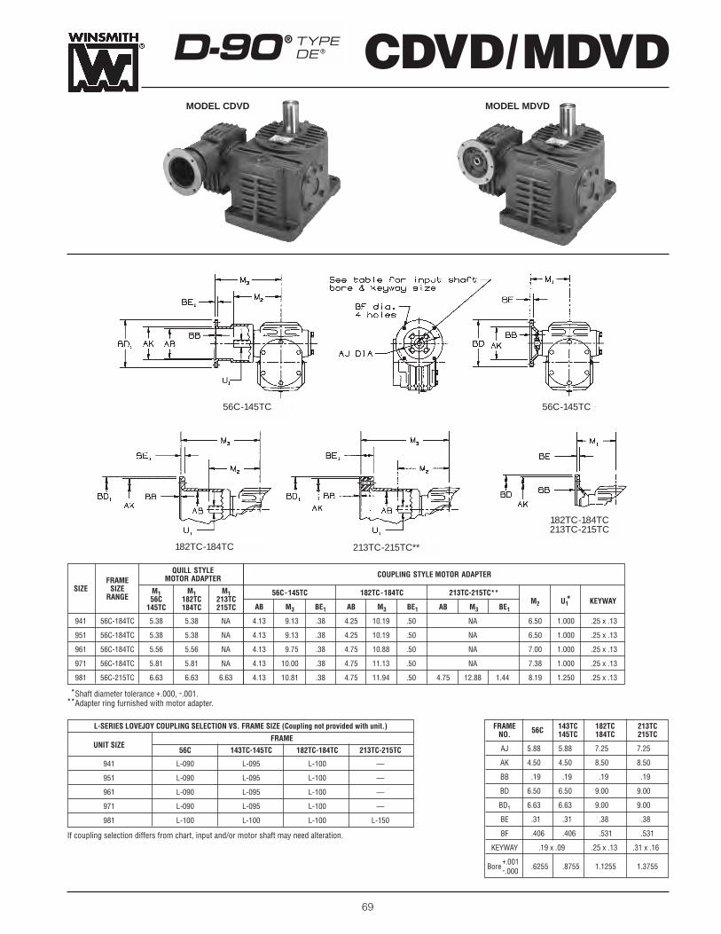
CDVD/MDVDD-90® TYPEDE®
MODEL CDVD MODEL MDVD
69The input shaft may be driven in either direction.
QUILL STYLEFRAME MOTOR ADAPTER
SIZE SIZE M1 M1 M1RANGE 56C 182TC 213TC145TC 184TC 215TC
941 56C-184TC 5.38 5.38 NA
951 56C-184TC 5.38 5.38 NA
961 56C-184TC 5.56 5.56 NA
971 56C-184TC 5.81 5.81 NA
981 56C-215TC 6.63 6.63 6.63
L-SERIES LOVEJOY COUPLING SELECTION VS. FRAME SIZE (Coupling not provided with unit.)
FRAMEUNIT SIZE
56C 143TC-145TC 182TC-184TC 213TC-215TC
941 L-090 L-095 L-100 —
951 L-090 L-095 L-100 —
961 L-090 L-095 L-100 —
971 L-090 L-095 L-100 —
981 L-100 L-100 L-100 L-150
COUPLING STYLE MOTOR ADAPTER
56C-145TC 182TC-184TC 213TC-215TC**
AB M3 BE1 AB M3 BE1 AB M3 BE1M2 U1* KEYWAY
4.13 9.13 .38 4.25 10.19 .50 NA 6.50 1.000 .25 x .13
4.13 9.13 .38 4.25 10.19 .50 NA 6.50 1.000 .25 x .13
4.13 9.75 .38 4.75 10.88 .50 NA 7.00 1.000 .25 x .13
4.13 10.00 .38 4.75 11.13 .50 NA 7.38 1.000 .25 x .13
4.13 10.81 .38 4.75 11.94 .50 4.75 12.88 1.44 8.19 1.250 .25 x .13
FRAME 143TC 182TC 213TCNO. 56C 145TC 184TC 215TC
AJ 5.88 5.88 7.25 7.25
AK 4.50 4.50 8.50 8.50
BB .19 .19 .19 .19
BD 6.50 6.50 9.00 9.00
BD1 6.63 6.63 9.00 9.00
BE .31 .31 .38 .38
BF .406 .406 .531 .531
KEYWAY .19 x .09 .25 x .13 .31 x .16
Bore+.001 .6255 .8755 1.1255 1.3755-.000
**Shaft diameter tolerance +.000, -.001.**Adapter ring furnished with motor adapter.
If coupling selection differs from chart, input and/or motor shaft may need alteration.
56C-145TC
182TC-184TC213TC-215TC
213TC-215TC**182TC-184TC
56C-145TC

SHAFT ARRANGEMENTS AND RELATIVE SHAFT ROTATIONS
††L3 dimension equals 5.46 on MDSFDmodels.
††L3 dimension equals 6.28 on MDSFDmodels.
*Shaft diameter tolerance +.000, -.001.�Bore tolerance +.000, +.002.▫ Check with factory for other bore sizes.
SIZE A B B1 C1 C2 D D1 E F1 F2 G H K1 K L1 L2 L3 M O
941 10.00 15.06 6.06 3.937 2.625 8.88 11.50 4.25 8.19 4.94 1.38 .69 4.94 4.44 5.78 10.90 4.50†† 6.50 13.69
951 11.00 17.27 6.58 4.921 2.625 10.92 13.55 4.38 9.44 5.31 1.50 .81 6.00 4.81 6.77 11.59 4.50†† 6.50 15.80
961 13.13 19.98 7.06 5.906 3.000 12.97 15.97 5.13 11.50 5.63 1.69 .94 7.06 5.70 8.47 13.26 4.63†† 7.00 18.15
971 15.38 23.31 8.45 6.890 3.500 15.20 18.70 6.31 13.25 6.88 2.00 1.06 8.31 6.56 9.39 15.45 5.06†† 7.38 22.33
981 17.13 25.54 9.19 7.874 4.250 17.06 21.31 6.88 14.44 7.31 2.13 1.19 9.19 6.88 10.45 17.54 5.88†† 8.19 24.82
GENERAL INFORMATION MODEL DSFD
The input shaft may be driven in either direction.
GEAR RATIO RANGE 100:1 THRU 10,000:1SINGLE REDUCTION VERSION . . . . . . . . . . . . . . . . . . . . PAGE 58††Weights are approximate and include shipping container.††Weight given for 56C -145TC, for larger frames add 5 pounds.
MODEL† 941 951 961 971 981
DSFD SHIPPING WEIGHT 209 293 400 640 880
MDSFD SHIPPING WEIGHT†† 213 297 404 644 885
CDSFD SHIPPING WEIGHT†† 218 302 410 650 890
APPROX. OIL CAPACITY (QUARTS) 5.9 5 8.5 13 17
HIGH SPEED SHAFT SLOW SPEED SHAFT BORES▫SIZE O1 P1 P2 R Y Y1 Z
U* N V KEYWAY W� KEYWAY W� KEYWAY
941 14.44 4.25 4.25 8.44 5.00 .75 4.13 1.000 2.75 2.38 .25 x .13 27⁄16 5⁄8 x 5⁄16 215⁄16 5⁄8 x 5⁄16
951 16.49 5.06 5.06 9.13 5.50 .44 4.88 1.000 2.75 2.38 .25 x .13 25⁄8 5⁄8 x 5⁄16 37⁄16 7⁄8 x 7⁄16
961 19.35 5.31 5.31 10.44 6.50 1.19 5.75 1.000 3.06 2.38 .25 x .13 3 3⁄4 x 3⁄8 315⁄16 1 x 3⁄8
971 22.24 6.69 6.69 12.63 7.00 .31 6.75 1.000 2.31 2.50 .25 x .13 31⁄4 3⁄4 x 3⁄8 47⁄16 1 x 1⁄2
981 24.19 6.30 6.30 14.63 8.00 1.70 6.75 1.250 2.31 2.50 25 x .13 33⁄4 7⁄8 x 7⁄16 47⁄16 1 x 1⁄2
ASSEMBLY DLSTANDARD
ASSEMBLY DRSTANDARD
CUSTOMER’SMACHINE
ASSEMBLY LD-DR
DSFD D-90® TYPEDE®
70
LU
LD
RU
RDASSEMBLY LU-DR
LU
LD
RU
UL
UR
RD
CUSTOMER’SMACHINE
NOTE:To identify double reduction unit assemblies, first list theletters designating the primary (smaller) housing shaftarrangements followed by a hyphen. After the hyphen, list the letter(s) designating the secondary (larger) housing shaft arrangements. These combined arrangements describe the double reduction
assembly. (See examples below)
ASSEMBLY DLSTANDARD
ASSEMBLY DRSTANDARD

CDSFD/MDSFDD-90® TYPEDE®
MODEL CDSFD MODEL MDSFD
71The input shaft may be driven in either direction.
QUILL STYLEFRAME MOTOR ADAPTER
SIZE SIZE M1 M1 M1RANGE 56C 182TC 213TC145TC 184TC 215TC
941 56C-184TC 5.38 5.38 NA
951 56C-184TC 5.38 5.38 NA
961 56C-184TC 5.56 5.56 NA
971 56C-184TC 5.81 5.81 NA
981 56C-215TC 6.63 6.63 6.63
L-SERIES LOVEJOY COUPLING SELECTION VS. FRAME SIZE (Coupling not provided with unit.)
FRAMEUNIT SIZE
56C 143TC-145TC 182TC-184TC 213TC-215TC
941 L-090 L-095 L-100 —
951 L-090 L-095 L-100 —
961 L-090 L-095 L-100 —
971 L-090 L-095 L-100 —
981 L-100 L-100 L-100 L-150
COUPLING STYLE MOTOR ADAPTER
56C-145TC 182TC-184TC 213TC-215TC**
AB M3 BE1 AB M3 BE1 AB M3 BE1M2 U1* KEYWAY
4.13 9.13 .38 4.25 10.19 .50 NA 6.50 1.000 .25 x .13
4.13 9.13 .38 4.25 10.19 .50 NA 6.50 1.000 .25 x .13
4.13 9.75 .38 4.75 10.88 .50 NA 7.00 1.000 .25 x .13
4.13 10.00 .38 4.75 11.13 .50 NA 7.38 1.000 .25 x .13
4.13 10.81 .38 4.75 11.94 .50 4.75 12.88 1.44 8.19 1.250 .25 x .13
FRAME 143TC 182TC 213TCNO. 56C 145TC 184TC 215TC
AJ 5.88 5.88 7.25 7.25
AK 4.50 4.50 8.50 8.50
BB .19 .19 .19 .19
BD 6.50 6.50 9.00 9.00
BD1 6.63 6.63 9.00 9.00
BE .31 .31 .38 .38
BF .406 .406 .531 .531
KEYWAY .19 x .09 .25 x .13 .31 x .16
Bore+.001 .6255 .8755 1.1255 1.3755-.000
**Shaft diameter tolerance +.000, -.001.**Adapter ring furnished with motor adapter.
If coupling selection differs from chart, input and/or motor shaft may need alteration.
56C-145TC
182TC-184TC213TC-215TC
213TC-215TC**182TC-184TC
56C-145TC

DSRD
72
*Shaft diameter tolerance +.000, -.001. �Bore tolerance +.000,+.002. ▫ Check with factory for other bore sizes. †L3 dimension=5.46 on MDSRD models. ††L3 dimension=6.28 on MDSRD models.
SHAFT ARRANGEMENTS AND RELATIVE SHAFT ROTATIONS
D-90® TYPEDE®
SIZE BB B1 C1 C2 D E F G H IMAX IMIN J K KK L1 L2 L3 M O
941 12.76 13.94 3.937 2.625 9.69 3.50 4.75 .56 .53 29.00 21.00 5.75 4.44 4.00 5.78 10.90 4.50†† 6.50 15.69
951 15.29 15.43 4.921 2.625 10.67 5.00 6.75 .75 .81 31.00 22.00 5.75 4.81 4.81 6.77 11.59 4.50†† 6.50 17.56
961 16.58 17.66 5.906 3.000 12.16 5.75 7.75 .88 .94 37.50 26.50 6.25 5.70 5.06 8.47 13.26 4.63†† 7.00 19.91
971 19.40 21.27 6.890 3.500 14.77 5.75 7.75 .88 .94 37.50 26.50 7.88 6.56 6.44 9.39 15.45 5.06†† 7.38 23.88
981 22.19 24.25 7.874 4.250 16.37 5.75 7.75 .88 .94 37.50 26.50 8.50 6.88 6.13 10.45 17.54 5.88†† 8.19 26.50
GENERAL INFORMATION MODEL DSRD
The input shaft may be driven in either direction.
GEAR RATIO RANGE 100:1 THRU 10,000:1SINGLE REDUCTION VERSION . . . . . . . . . . . . . . . . . . . . PAGE 60††Weights are approximate and include shipping container.††Weight given for 56C -145TC, for larger frames add 5 pounds.
MODEL† 941 951 961 971 981
DSRD SHIPPING WEIGHT 245 358 490 780 1030
MDSRD SHIPPING WEIGHT†† 249 362 494 784 1035
CDSRD SHIPPING WEIGHT†† 254 367 500 790 1040
APPROX. OIL CAPACITY (QUARTS) 2.7 3.5 4.5 9 12
NOTE:
To identify double reduction unit assemblies, first list the letters designatingthe primary (smaller) housing shaft arrangements followed by a hyphen. Afterthe hyphen, list the letter(s) designating the secondary (larger) housing shaft arrangements. These combined arrangements describe the double reduction assembly. (See examples below)
SIZE O1 P1 P2 Q1 R S X Y Y1 Z
941 11.31 4.25 4.25 12.94 8.44 2.13 1.63 2.25 1.44 4.13
951 11.31 5.06 5.06 14.30 9.14 2.06 1.94 2.88 1.94 4.88
961 12.63 5.31 5.31 16.41 10.44 2.69 2.38 3.25 2.19 5.75
971 14.92 6.69 6.69 20.02 12.63 2.69 2.38 3.88 2.44 6.75
981 15.63 6.30 6.30 23.00 14.63 2.69 2.38 4.25 2.63 6.75
HIGH SPEED SHAFT SLOW SPEED SHAFT BORES▫
U* N V KEYWAY W� KEYWAY W� KEYWAY
1.000 2.75 2.38 .25 x .13 27⁄16 5⁄8 x 5⁄16 215⁄16 5⁄8 x 5⁄16
1.000 2.75 2.38 .25 x .13 25⁄8 5⁄8 x 5⁄16 37⁄16 7⁄8 x 7⁄16
1.000 3.06 2.38 .25 x .13 3 3⁄4 x 3⁄8 315⁄16 1 x 3⁄8
1.000 2.31 2.50 .25 x .13 31⁄4 3⁄4 x 3⁄8 47⁄16 1 x 1⁄2
1.250 2.31 2.50 .25 x .13 33⁄4 7⁄8 x 7⁄16 47⁄16 1 x 1⁄2
ASSEMBLY DLSTANDARD
ASSEMBLY DRSTANDARD
ASSEMBLY LD-DR
LU
LD
RU
RD
ASSEMBLY DLSTANDARD
ASSEMBLY LU-DR
LULD
RU RD
ASSEMBLY DRSTANDARD

D-90® TYPEDE® CDSRD/MDSRD
MODEL CDSRD MODEL MDSRD
73The input shaft may be driven in either direction.
QUILL STYLEFRAME MOTOR ADAPTER
SIZE SIZE M1 M1 M1RANGE 56C 182TC 213TC145TC 184TC 215TC
941 56C-184TC 5.38 5.38 NA
951 56C-184TC 5.38 5.38 NA
961 56C-184TC 5.56 5.56 NA
971 56C-184TC 5.81 5.81 NA
981 56C-215TC 6.63 6.63 6.63
L-SERIES LOVEJOY COUPLING SELECTION VS. FRAME SIZE (Coupling not provided with unit.)
FRAMEUNIT SIZE
56C 143TC-145TC 182TC-184TC 213TC-215TC
941 L-090 L-095 L-100 —
951 L-090 L-095 L-100 —
961 L-090 L-095 L-100 —
971 L-090 L-095 L-100 —
981 L-100 L-100 L-100 L-150
COUPLING STYLE MOTOR ADAPTER
56C-145TC 182TC -184TC 213TC-215TC**
AB M3 BE1 AB M3 BE1 AB M3 BE1M2 U1* KEYWAY
4.13 9.13 .38 4.25 10.19 .50 NA 6.50 1.000 .25 x .13
4.13 9.13 .38 4.25 10.19 .50 NA 6.50 1.000 .25 x .13
4.13 9.75 .38 4.75 10.88 .50 NA 7.00 1.000 .25 x .13
4.13 10.00 .38 4.75 11.13 .50 NA 7.38 1.000 .25 x .13
4.13 10.81 .38 4.75 11.94 .50 4.75 12.88 1.44 8.19 1.250 .25 x .13
FRAME 143TC 182TC 213TCNO. 56C 145TC 184TC 215TC
AJ 5.88 5.88 7.25 7.25
AK 4.50 4.50 8.50 8.50
BB .19 .19 .19 .19
BD 6.50 6.50 9.00 9.00
BD1 6.63 6.63 9.00 9.00
BE .31 .31 .38 .38
BF .406 .406 .531 .531
KEYWAY .19 x .09 .25 x .13 .31 x .16
Bore+.001 .6255 .8755 1.1255 1.3755-.000
**Shaft diameter tolerance +.000, -.001.**Adapter ring furnished with motor adapter.
If coupling selection differs from chart, input and/or motor shaft may need alteration.
56C-145TC
182TC-184TC213TC-215TC
213TC-215TC**182TC-184TC
56C-145TC

74
D-90® TYPEDE®
*Shaft diameter tolerance +.000, -.001.
SHAFT ARRANGEMENTS AND RELATIVE SHAFT ROTATIONS
SIZE∑ A C1 C2 D E G H J K K1 L1 L2 L3 M O O1 P R X
951 17.50 4.921 2.625 8.00 7.63 1.50 .81 .25 8.11 6.88 6.77 11.59 4.50 11.42 13.63 13.56 23.50 9.13 6.50
961 19.38 5.906 3.000 9.50 8.44 1.75 .94 .38 9.06 7.75 8.47 13.26 4.63 12.91 15.88 15.88 26.00 10.44 7.00
GENERAL INFORMATION MODEL DLD
The input shaft may be driven in either direction.
GEAR RATIO RANGE 100:1 THRU 10,000:1SINGLE REDUCTION VERSION . . . . . . . . . . . . . . . . . . . . PAGE 62†Weights are approximate and include shipping container.††Weight given for 56C -145TC, for larger frames add 5 pounds.
MODEL† 951 961
DLD SHIPPING WEIGHT 508 700
MDLD SHIPPING WEIGHT†† 512 704
CDLD SHIPPING WEIGHT†† 517 710
APPROX. OIL CAPACITY (QUARTS) 9 15
BOLTCIRCLE
HIGH SPEED SHAFT SLOW SPEED SHAFT Y DIMENSIONSSIZE
U* N V KEYWAY W* S S2 T KEYWAY TAP DEPTH
951 1.000 2.75 2.38 .25 x .13 2.938 7.81 15.50 7.56 3⁄4 x 3⁄8 3⁄8 - 16 1.00 2.00
961 1.000 3.06 2.38 .25 x .13 3.500 8.80 16.50 8.75 7⁄8 x 7⁄16 5⁄8 - 11 1.50 2.25
ASSEMBLY RDSTANDARD
ASSEMBLY RU-LD
ASSEMBLY LDSTANDARD
LU
RU
DLD
∑For information on sizes 941, 971 and 981, contact factory.
ULASSEMBLY RU-LD
ASSEMBLY LDSTANDARD
ASSEMBLY RDSTANDARD
RU
UR
LU
NOTE:To identify double reduction unit assemblies, first listthe letters designating the primary (smaller) housingshaft arrangements followed by a hyphen. After thehyphen, list the letter(s) designating the secondary(larger) housing shaft arrangements. These combined arrangements describe the double reduction assembly. (See examples below)

CDLD/MDLDD-90® TYPEDE®
MODEL CDLD MODEL MDLD
75The input shaft may be driven in either direction.
QUILL STYLEFRAME MOTOR ADAPTER
SIZE SIZE M1 M1 M1RANGE 56C 182TC 213TC145TC 184TC 215TC
951 56C-184TC 5.38 5.38 NA
961 56C-184TC 5.56 5.56 NA
L-SERIES LOVEJOY COUPLING SELECTION VS. FRAME SIZE (Coupling not provided with unit.)
FRAMEUNIT SIZE
56C 143TC-145TC 182TC-184TC 213TC-215TC
951 L-090 L-095 L-100 —
961 L-090 L-095 L-100 —
COUPLING STYLE MOTOR ADAPTER
56C-145TC 182TC-184TC 213TC-215TC**
AB M3 BE1 AB M3 BE1 AB M3 BE1M2 U1* KEYWAY
4.13 9.13 .38 4.25 10.19 .50 NA 6.50 1.000 .25 x .13
4.13 9.75 .38 4.75 10.88 .50 NA 7.00 1.000 .25 x .13
FRAME 143TC 182TC 213TCNO. 56C 145TC 184TC 215TC
AJ 5.88 5.88 7.25 7.25
AK 4.50 4.50 8.50 8.50
BB .19 .19 .19 .19
BD 6.50 6.50 9.00 9.00
BD1 6.63 6.63 9.00 9.00
BE .31 .31 .38 .38
BF .406 .406 .531 .531
KEYWAY .19 x .09 .25 x .13 .31 x .16
Bore+.001 .6255 .8755 1.1255 1.3755-.000
**Shaft diameter tolerance +.000, -.001.**Adapter ring furnished with motor adapter.
If coupling selection differs from chart, input and/or motor shaft may need alteration.
56C-145TC
182TC-184TC213TC-215TC
213TC-215TC**182TC-184TC
56C-145TC
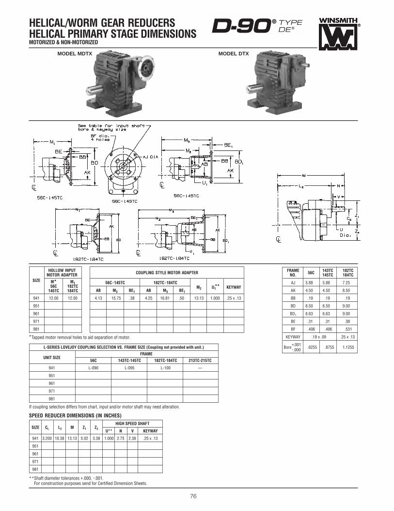
COUPLING STYLE MOTOR ADAPTER
56C-145TC 182TC-184TC
AB M3 BE1 AB M3 BE1M2 U1** KEYWAY
4.13 15.75 .38 4.25 16.81 .50 13.13 1.000 .25 x .13
SPEED REDUCER DIMENSIONS (IN INCHES)
HELICAL/WORM GEAR REDUCERSHELICAL PRIMARY STAGE DIMENSIONSMOTORIZED & NON-MOTORIZED
D-90® TYPEDE®
76
HOLLOW INPUTMOTOR ADAPTER
SIZE M* M156C 182TC
145TC 184TC
941 12.00 12.00
951
961
971
981
*Tapped motor removal holes to aid separation of motor.
FRAME 143TC 182TCNO. 56C 145TC 184TC
AJ 5.88 5.88 7.25
AK 4.50 4.50 8.50
BB .19 .19 .19
BD 6.50 6.50 9.00
BD1 6.63 6.63 9.00
BE .31 .31 .38
BF .406 .406 .531
KEYWAY .19 x .09 .25 x .13
Bore+.001 .6255 .8755 1.1255-.000
L-SERIES LOVEJOY COUPLING SELECTION VS. FRAME SIZE (Coupling not provided with unit.)
FRAMEUNIT SIZE
56C 143TC-145TC 182TC-184TC 213TC-215TC
941 L-090 L-095 L-100 —
951
961
971
981
If coupling selection differs from chart, input and/or motor shaft may need alteration.
SIZE CL L2 M Z1 Z2
HIGH SPEED SHAFT
U** N V KEYWAY
941 3.200 10.38 13.13 5.02 3.38 1.000 2.75 2.38 .25 x .13
951
961
971
981
**Shaft diameter tolerances +.000, -.001. For construction purposes send for Certified Dimension Sheets.
MODEL MDTX MODEL DTX
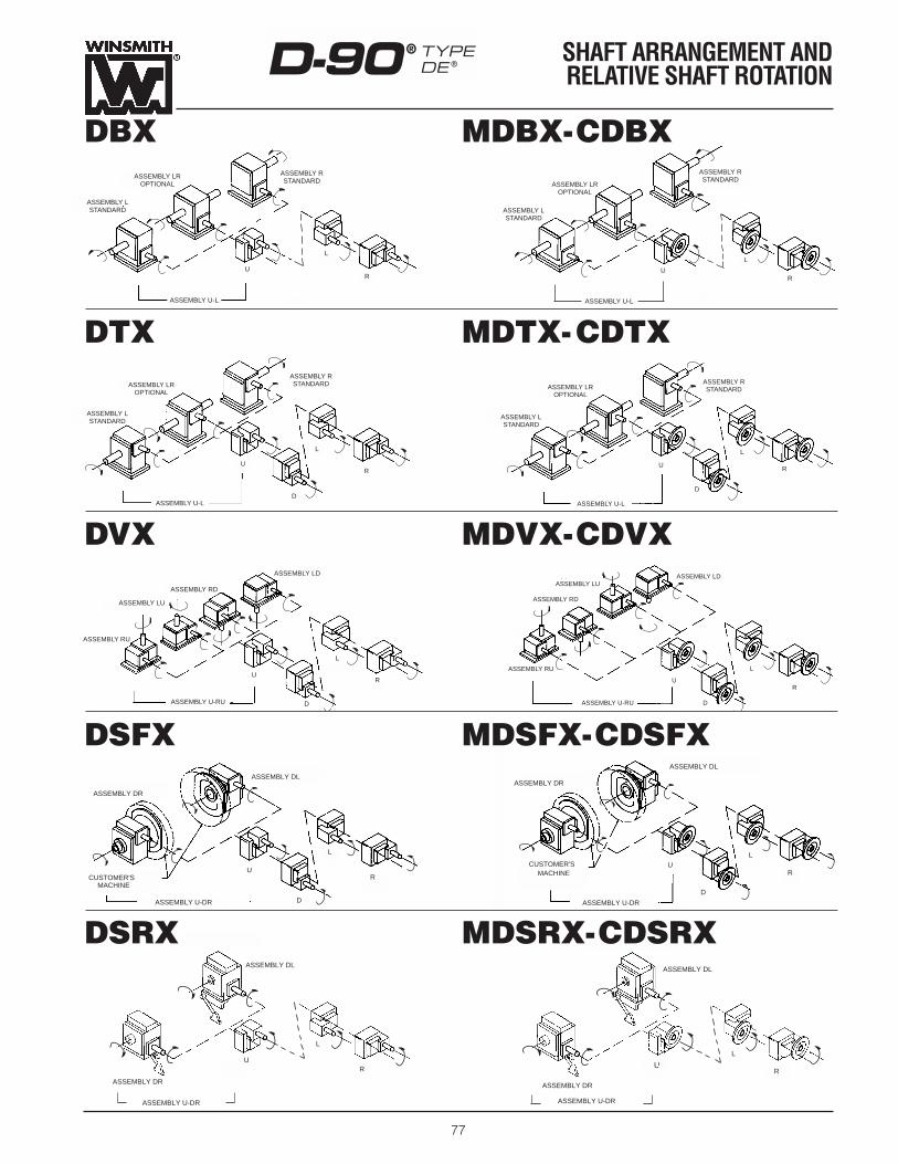
ASSEMBLY DL
ASSEMBLY DR
CUSTOMER'SMACHINE
ASSEMBLY U-DR
U
D
L
R
ASSEMBLY DL
CUSTOMER’SMACHINE
ASSEMBLY DR
ASSEMBLY U-DR
U
D
L
RU
D
L
R
ASSEMBLY DL
ASSEMBLY DR
CUSTOMER'SMACHINE
ASSEMBLY U-DR
ASSEMBLY RU
ASSEMBLY RD
ASSEMBLY LUASSEMBLY LD
ASSEMBLY U-RU
U
D
L
R
ASSEMBLY RD
ASSEMBLY LU
ASSEMBLY U-RU
U
D
L
R
ASSEMBLY LD
ASSEMBLY RU
77
D-90® TYPEDE®
SHAFT ARRANGEMENT AND RELATIVE SHAFT ROTATION
ASSEMBLY LROPTIONAL
ASSEMBLY LSTANDARD
ASSEMBLY U-L
U
L
R
ASSEMBLY RSTANDARD
ASSEMBLY LSTANDARD
ASSEMBLY U-L
U
L
R
ASSEMBLY RSTANDARD
ASSEMBLY LROPTIONAL
ASSEMBLY LROPTIONAL
ASSEMBLY LSTANDARD
ASSEMBLY U-L
U
D
L
R
ASSEMBLY RSTANDARD ASSEMBLY LR
OPTIONAL
ASSEMBLY LSTANDARD
ASSEMBLY U-L
U
D
L
R
ASSEMBLY RSTANDARD
MDBX-CDBXDBX
DTX MDTX-CDTX
DVX MDVX-CDVX
DSFX MDSFX-CDSFX
U
L
R
ASSEMBLY DL
ASSEMBLY DR
ASSEMBLY U-DR
ASSEMBLY DL
ASSEMBLY DR
U
L
R
ASSEMBLY U-DR
DSRX MDSRX-CDSRX

D-90® TYPEDE®
STANDARD SINGLE EXTENDED DOUBLE ENVELOPING WORMS
78
SIZE J K L1 L2 L3 M N S S1 T U V KEYWAY FAN EXTKEYWAY
941 5.768 NA 15.69 13.28 2.41 9.00 .75 2.561 2.561 NA 1.500 3.25 3/8 x 3/16 1/4 x 1/8
951 5.524 NA 17.82 14.98 2.84 9.73 .79 2.800 2.800 1.772 1.500 3.06 3/8 x 3/16 5MM x 3MM
961 5.834 .64 21.22 18.85 2.37 11.10 .98 2.652 2.502 1.969 1.750 3.12 3/8 x 3/16 7MM x 4MM
971 7.932 .75 24.98 21.94 3.04 13.25 1.15 3.250 3.250 2.165 1.750 4.25 3/8 x 3/16 7MM x 4MM
981 9.575 .75 27.90 25.17 2.73 15.50 1.38 3.250 3.250 2.362 2.000 5.47 1/2 x 1/4 10MM x 4MM4
SIZE B1 B2 BRG1 BRG2 CD D E F F1 F2 F3 G
941 3.2352 NA 1.7515 1.7515 3.937 6.465 .25 2.179 1.000 NA 1.500 1.05
951 4.2007 NA 2.0007 2.0007 4.921 8.403 .38 2.321 .7091 .986 1.772 1.05
961 4.634 NA 2.2507 1.9697 5.906 9.902 .50 2.604 1.102 1.772 NA 1.48
971 NA 5.318 2.3634 2.3634 6.890 10.303 .75 3.539 1.299 2.165 NA 1.18
981 NA 5.925 2.7507 2.5603 7.874 11.850 1.00 3.914 1.674 2.362 NA 1.38
Dashed line indicates fanextension.
Double extended availableupon request.
Worms and gears sold asmatched set only.
The mechanical rating canbe found in the unit ratingsection of this catalog.
SIZE 941 SIZE 951 SIZE 961 SIZE 971 SIZE 981
RATIOWORM
RATIOWORM
RATIOWORM
RATIOWORM
RATIOWORM
OD L OD L OD L OD L OD L
5 2.877 1.322 5 3.870 1.992 5 4.422 2.010 5 5.257 3.076 5 5.992 2.882
8 2.326 1.420 8 3.700 2.266 8 4.286 2.680 8 4.494 3.162 8 5.371 4.014
10 2.254 1.532 10 3.319 2.294 10 4.022 2.686 10 4.640 3.340 10 5.137 4.014
15 2.673 1.888 15 3.571 2.392 15 3.839 2.852 15 3.808 3.358 15 4.743 4.032
20 2.518 1.814 20 3.366 2.430 20 3.679 2.880 20 3.935 3.340 20 4.879 4.012
25 2.021 1.834 25 2.734 2.438 25 3.561 2.902 25 3.462 3.372 25 3.918 4.048
30 2.090 2.192 30 2.658 2.658 30 3.386 3.120 30 3.311 3.394 30 3.778 4.074
40 2.233 2.140 40 2.846 2.422 40 3.207 3.252 40 3.787 3.524 40 4.162 4.012
50 2.155 2.058 50 2.776 2.598 50 3.056 3.178 50 3.558 3.564 50 3.887 4.046
60 2.065 2.034 60 2.657 2.516 60 2.906 3.102 60 3.460 3.682 60 3.807 4.172
70 1.986 2.048 70 2.569 2.490 70 2.834 3.116 70 3.373 3.700 70 3.377 4.192
80 1.918 1.956 80 2.495 2.440 80 2.769 3.126 80 3.286 3.614 80 3.363 4.204
100 1.850 1.966 100 2.454 2.552 100 2.647 3.044 100 3.185 3.630 100 3.203 4.232
RATIO CHART
Check with factory for other dimensions.Dimensions could be changed by WINSMITH without notice.

79
SIZERATIO
5 8 10 15 20 25 30 40 50 60 70 80 100
941 5.684 6.404 6.404 6.189 6.189 6.609 6.609 6.609 6.609 6.609 6.609 6.609 6.609
951 6.944 7.324 7.544 7.544 7.544 8.204 8.204 8.204 8.204 8.204 8.204 8.204 8.204
961 8.364 8.744 9.004 9.404 9.404 9.404 10.044 10.044 10.044 10.044 10.044 10.044 10.044
971 9.804 10.664 10.664 11.504 11.504 11.764 11.764 11.764 11.764 11.764 11.764 11.764 11.764
981 11.104 12.184 12.404 12.684 12.684 13.504 13.504 13.504 13.504 13.504 13.724 13.724 13.724
SIZE CD BORE DIA KEYWAY HUB FACEWIDTH WIDTH
941 3.937 2.2492 / 2.2506 1/2 x 1/4 2.502 / 2.498 1.230
951 4.921 2.6242 / 2.6256 3/4 x 3/8 3.152 / 3.148 1.450
961 5.906 3.1871 / 3.1844 3/4 x 3/8 4.333 / 4.329 1.731
971 6.890 3.6606 / 3.6622 1 x 1/2 5.120 / 5.119 2.060
981 7.874 3.9996 / 4.0009 1 x 1/2 6.302 / 6.298 2.305
SIZE CD BORE DIA KEYWAY HUB FACEWIDTH WIDTH
941 3.937 4.2496 / 4.2509 1/2 x 1/4 3.002 / 2.998 1.230
951 4.921 4.9990 / 5.0006 5/8 x 5/16 4.127 / 4.123 1.450
961 5.906 5.7490 / 5.7506 3/4 x 3/8 3.627 / 3.623 1.731
971 6.890 6.9990 / 7.0006 1 x 1/2 5.002 / 4.998 2.060
981 7.874 6.9990 / 7.0000 1 x 1/2 5.574 / 5.570 2.305
CAST IRONINSERT USED SOLID
BRONZE CONSULT FACTORY
MADE TO CUSTOMER SPECIFICATIONS
DIMENSION CHART SOLID SHAFT GEAR HOLLOW SHAFT AND FLANGE GEAR
GEAR OD (ALL 3 STYLES)
Check with factory for other dimensions.Dimensions could be changed by WINSMITH without notice.
STANDARD AND OPTIONAL GEARSFOR DOUBLE ENVELOPING GEAR SETSD-90® TYPE
DE®

8080
STANDARD SOLID GEARSHAFTS D-90® TYPEDE®
SOLID SLOW SPEED SHAFTS
CENTER EXTENSION GEAR B W W2SIZE DISTANCE KEYWAY KEYWAY FULL C D E F G P T -.001- W1 -.0005-DEPTH
941 3.937 1/2 x 1/47 1/2 x 1/4 2.50 8.00 4.00 1.00 NA NA 9.25 4.19 2.250 NA 2.2515
951 4.921 5/8 x 5/16 3/4 x 3/8 3.15 8.00 4.00 1.13 NA NA 9.38 4.13 2.500 NA 2.6265
961 5.906 3/4 x 3/87 3/4 x 3/8 4.33 9.55 4.80 1.38 NA NA 11.50 5.25 3.125 NA *3.190*0∑971∑ 6.890 7/8 x 7/16 3/1 x 1/2 5.13 7.62 3.81 1.38 1.63 3.01 13.50 6.56 3.500 3.545 *3.6635*
981 7.874 7/1 x 1/27 3/1 x 1/2 6.19 12.56 6.31 1.44 NA NA 15.50 7.69 3.875 NA 4.0025
Material—Steel ∑See alternate view.*Use these shafts with solid shaft gears.*Check with factory for other dimensions.*Dimensions could be changed by WINSMITH without notice.*Tolerance W2 size 961 is 3.190/3.189.*Tolerance W2 size 971 is 3.6635/3.6628.
GEAR KEYWAY
SECTION A-A W
P P
C
B
AE
E
T
D
W
WW2
F
W1
GASEAL AREA SEAL AREA
EXTENSIONKEYWAY
SEALAREA971
T
W2
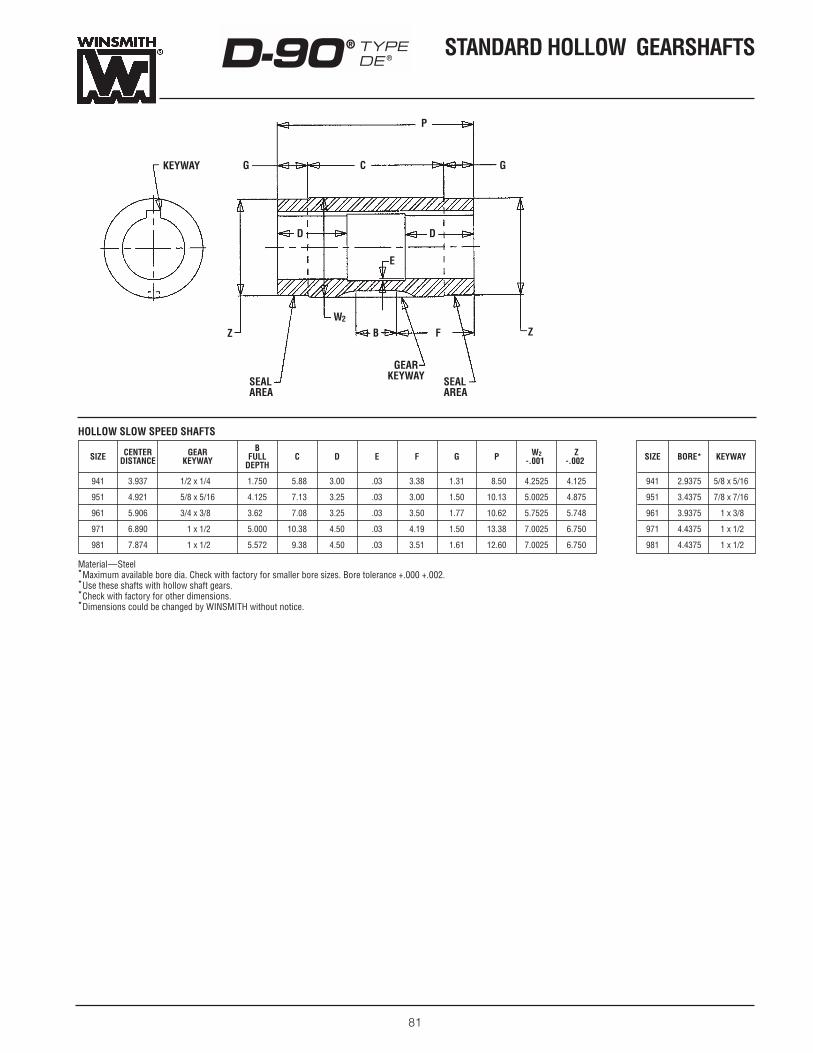
81
HOLLOW SLOW SPEED SHAFTS
CENTER GEAR B W2 ZSIZE DISTANCE KEYWAY FULL C D E F G P -.001- -.002-DEPTH
941 3.937 1/2 x 1/47 1.750 25.88 3.00 .03 3.38 1.31 28.50 4.2525 4.125
951 4.921 5/8 x 5/16 4.125 27.13 3.25 .03 3.00 1.50 10.13 5.0025 4.875
961 5.906 3/4 x 3/87 3.622 27.08 3.25 .03 3.50 1.77 10.62 5.7525 5.748
971 6.890 7/1 x 1/27 5.000 10.38 4.50 .03 4.19 1.50 13.38 7.0025 6.750
981 7.874 7/1 x 1/27 5.572 29.38 4.50 .03 3.51 1.61 12.60 7.0025 6.750
SIZE BORE* KEYWAY
941 2.9375 5/8 x 5/16
951 3.4375 7/8 x 7/16
961 3.9375 7/1 x 3/86
971 4.4375 7/1 x 1/26
981 4.4375 7/1 x 1/26
Material—Steel *Maximum available bore dia. Check with factory for smaller bore sizes. Bore tolerance +.000 +.002.*Use these shafts with hollow shaft gears.*Check with factory for other dimensions.*Dimensions could be changed by WINSMITH without notice.
STANDARD HOLLOW GEARSHAFTSD-90® TYPEDE®
GEAR KEYWAY
E
W2
Z ZB F
SEALAREA
SEALAREA
KEYWAY G GC
P
D D

82
STANDARD MOUNTING POSITIONS D-90® TYPE
DE®
Filler
Vent
Level
Drain
Grease Fitting
*Contact the factorywhen input speedsare less than 1160RPM.
DBD DTD DVD
DSFD DSRD DLD
Figure 2. Double Reduction Models
MAIN HOUSING
ATTACHMENT HOUSING—NON-MOTORIZED* ATTACHMENT HOUSING—MOTORIZED*
F
V
L
D
GF
SIZES 941- 961
SIZES 971- 981
DB DT DV
DSF DSR DL
Figure 1. Single Reduction Models

D-90® TYPEDE® STANDARD MOUNTING
POSITIONS
83
DBX DTX DVX
DSFX DSRX DLX
Figure 3. Helical/Worm Gear Double Reduction Models
F
L
D
D
D
D
F
F
F
L
L
L
F F
L L
L
D D
D
F F
L
D
Filler
Vent
Level
Drain
Grease Fitting
*Contact the factorywhen input speedsare less than 1160RPM.
MAIN HOUSING
ATTACHMENT HOUSING—NON-MOTORIZED* ATTACHMENT HOUSING—MOTORIZED*
F
V
L
D
GF

84
NOTES WINSMITH
-----lIir

HORSEPOWER AND TORQUEOne (1) Horsepower (HP)—33,000 foot pounds of workdone in one (1) minute. Note that three (3) factors areinvolved:
Distance —FeetForce—(Push or Pull) —PoundsTime —Minutes
Putting it another way, one (1) HP is equivalent to raising33,000 pounds, one foot in one minute. Any amount of horse-power can be determined by the following formula:
HP = L (Load in pounds) x Feet per minute33,000
To determine the relationship between horsepower andtorque let
HP= HorsepowerT = Torque, in foot-poundst = Torque, in inch-poundsN = R.P.M. (Revolutions
per minute)
Then, one (1) HP = A Torque Load (Twisting force) of 63,025inch pounds, turning 1 revolution in1 minute.
therefore,
HP = t X N or T X N ; t = 63,025 x HP or T = 5250 x HP63,025 5250. N N
EFFICIENCY OF SPEED REDUCERSThe efficiency of a Worm Gear Speed Reducer is dependenton many factors including; input HP, input speed, lead angleof the worm, lubricant and operating temperature.
Efficiencies at rated conditions are listed in the catalog, andwere calculated in the following manner:
Efficiency = Horsepower OutputHorsepower Input
In order to establish the efficiencies of reducers where only theoutput torque and input horsepower are given, the outputtorque is converted to output horsepower by the following for-mula:
Horsepower Output = Output Torque x RPM Output63,025
To determine efficiency of the unit, the horsepower output isdivided by horsepower input as previously shown.
SELF-LOCKING SPEED REDUCERSWORM GEAR REDUCERSA worm gear is said to be self-locking, or irreversible whenthe gear cannot drive the worm. This condition is obtained, ifthe lead angle of the worm is less than the friction angle, andas a consequence the efficiency for reversed driving is zero.The friction angle for static conditions will vary with such factorsas surface finish and lubrication. Based upon the generallyaccepted value of static coefficient of friction equal to 0.15,the friction angle would be approximately 8°. However, thefriction angle decreases rapidly with the start of motion, also,vibrations from nearby sources quite often upset the staticcondition of a locked set of gearing a sufficient amount toreduce the friction angle to a point where motion occurs.These unpredictable factors make it advisable to resort to abrake rather than to rely on the self-locking characteristics ofthe gearing. A worm gear set has the following SELF-Lockingqualities “at rest” or “in motion”.
CASE 1—Self-locking of the worm and gear when the load isat rest may occur with the helix angle as great as 6°. However
vibrations from an outside source, or the slightest start of theworm often upsets the static condition of a locked set of gear-ing a sufficient amount to start motion.
CASE 2—Self-locking of the worm and gear when the loadis in motion downward requires that the load being loweredstops after the power is shut off. Worms with a helix angle of2° or less may be required for this service.
OVERDRIVESIn the overdriving of a reducer, the slow speed shaft is the driver, and the high speed shaft is increased in speed. Forthis type of service there must not be the slightest tendencyof the reducer to be self-locking. All applications regardingself-locking or overdrives should be referred to our engineeringdepartment for recommendations.
AGMA RECOMMENDS the following with regard to self-lock-ing. “For complete assurance of irreversibility, it is advisableto resort to the use of a brake rather than to rely on self-lock-ing characteristics of the gearing.”
ENGINEERING DATA
85

ENGINEERING DATA
86
BACKLASHBacklash is defined as the rotational arc clearance between a pair of mounted gears. In any gearset, some amount ofbacklash (clearance) is necessary to prevent damage broughtabout by gear tooth interference. Lack of backlash may causenoise, overloading, overheating of gears and bearings andeven seizing and failure.
Backlash is measured by restricting the rotation of onemember, usually the pinion, and measuring the rotationalmovement of the other component at some reference radius.WINSMITH® has historically used three inches as a referenceradius, but any convenient distance is applicable, rememberingthat greater distances will result in more accurate measure-ments. Backlash is usually stated in arc degrees (minutes/seconds). The resulting arc movement measurement can beconverted to degrees using the following equation:
Backlash (degrees) = Arc Movement (inches) x 57.296Radius (inches)
The resulting decimal can be converted to minutes andseconds by multiplying by 60 (minutes/degree). The integervalue is the arc minutes. The arc seconds are obtained bymultiplying the decimal remainder again by 60.
Example:.18 degrees x 60 = 10.8 minutes.8 remainder x 60 = 48 seconds
so .18 degrees = 10 minutes and 48 seconds
When measuring the backlash in worm gear units, the arcmovement of the slow speed shaft (gear) is measured whilerestricting the rotation of the input shaft (worm). It is not correct to measure the worm arc movement while restrictingthe gear rotation as this result will be much greater and is notindicative of tooth clearance (backlash). Axial clearances inthe high speed worm bearings will add to the arc movementof the gear and “appear” to be backlash. This clearance isminimal and for most applications, is of no consequence.However, when close backlash is required, bearing endplaymust be considered and reduced if necessary.
Tolerance variations in the related components will affectbacklash. These include housing center distance variations,gear geometry tolerances and bearing runout. These andother issues must be considered when establishing a designspecification for backlash. Closer tolerances in the housingand gear geometry along with higher precision bearings combine to provide closer backlash control, enabling tighterbacklash when needed but at a greater cost. Therefore, themaximum allowable backlash for the application should bespecified.
WINSMITH double enveloping reducers have a maximumstandard backlash of between .010 and .015 inches on a 3 inch radius, depending on unit size and ratio.
RUN-INThe running-in of double enveloping wormgearing immediatelyafter start-up may not always be necessary, but doing so is certainly advantageous. No matter how well finished worm-gearing surfaces may be, they do require some time to run-in to conform and obtain a work hardened surface on the bronzeand achieve rated efficiency. The gearing has a better chanceof providing maximum performance if the initial working can bedone gradually.
Experience indicates that the initial friction is 10 to 15 percent higher than that which will be obtained after run-in iscompleted. The first few hours of operation at graduallyincreasing loads reduces the friction and the efficiency settlesdown to a steady value after about 10-100 hours of operation,
depending on the size and speed of the gearing and the oper-ating load. A reasonable run-in procedure is to apply one-halfload for a few hours and then increase to the operating loadin at least two stages.
An immediate application of full load concentrates highcontact pressures on small areas which may cause sometemporary damage to the surfaces and may cause high localsurface temperatures. The temporary damage to the bronzegear surfaces will often “heal” after continued running at fullor less than full load. The run-in of wormgearing at graduallyincreasing loads can prevent the occurance of such surfacedamage.

ENGINEERING DATA
87
All catalog ratings are based on 10 hours per day operationwith uniform loading equating to a service factor of 1.0. Whenoperating conditions differ, the following chart can be used to determine the appropriate service factor. For applications
SERVICE FACTORS
Hours/Day Uniform Moderate Heavy ExtremeShock Shock Shock
1⁄2 .8 .8 .9 1.1
1 .8 .9 1.0 1.2
2 .9 1.0 1.2 1.3
10 1.0 1.2 1.3 1.5
24 1.2 1.3 1.5 1.75
SERVICE FACTORS FOR FREQUENT START AND STOP APPLICATIONS
Hours/Day Uniform Moderate Heavy ExtremeShock Shock Shock
1⁄2 .9 .9 1.0 1.2
1 .9 1.0 1.2 1.3
2 1.0 1.2 1.3 1.5
10 1.2 1.3 1.5 1.75
24 1.3 1.5 1.75 2.0
SYNTHETIC LUBRICANT RECOMMENDATIONS
Ambient Temperature -30°F to 15°F 16°F to 165°F
Max. Operating Temperature 185°F 200°F
Mobil SHC 629 Mobil SHC 634*Recommended Lubricant or or
Equivalent Equivalent
involving more than 10 starts per hour, refer to the servicefactor chart entitled, “Service Factors For Frequent Start and Stop Applications”.
Normal starting or occasional peak loads up to 300% of catalog ratings at 1800 RPM are permissible. The appliedloads should not exceed two seconds duration and the numberof applied loads should not exceed a total of 25,000 occur-rences over the life of the unit. If any of these conditions areexceeded, consult the factory.
Reversing drives and those subjected to quickly repeatedshock loads of unusual or unpredictable intensity; stallingloads and drives that are overrunning, or that “wind up’’ due to
quick power stoppage and storage of energy are not coveredby service factors above. A service factor of three may beapplicable, however, each is a problem in itself and should bereferred to the factory.
Service factors should be calculated using the prime moverhorsepower as applied to the unit mechanical ratings.However, the unit thermal capacity must not be exceeded ona continuous basis. Refer to the rating charts for mechanicaland thermal capacities.
SERVICE FACTORS
The HP and torque ratings in this catalog have been estab-lished using a synthetic hydrocarbon lubricant which providesoptimum performance in both torque transmission and efficiency. All units are shipped with the proper amount ofsynthetic lubricant for the stated mounting position. When
adding or changing oil, the replacement lubricant should be of this type. Mixing mineral oil with the synthetic may have aserious detrimental effect on performance and could result indamage to the internal components. Refer to the DE ProductMaintenance Bulletin for further information.
LUBRICATION
*Furnished unless otherwise specified.

88
ENGINEERING DATA
EXAMPLE:Assume that a 951 FDT Reducer with a reduction of 50 to 1, operating at 1750 RPM input, is subjected to a torque of13,500 inch pounds on the slow speed shaft. This torque istransmitted through a double chain sprocket of 1.50" pitch 13 teeth. The centerline of the sprocket is 8.00 inches fromthe center of the Reducer and the chain pull is directed towardthe base. The service is 24 hours per day, uniform loading.
DATA:Service Factor = 1.25
Chain Overhung Load Factor = 1 (from Table I)
Radius of 13 Tooth 1.50" Pitch Chain= 6.268"/2 = 3.134"
Catalog Overhung Load = Lc = 6158
CL Reducer to a point one shaftdiameter from the housing or mounting flange. = 7.500
� l = 8.0"- 7.5" = 0.50"l = 4.428" (from Table II)
DesignOverhung = TORQUE x SERVICE x OHL = 13,500 x 1.25 x 1.00 = 5384#
Load RADIUS FACTOR FACTOR 3.134"
AllowableOverhung = La = Lc l = 6158 4.428 = 5533#
Load l + � l 4.428"+ 0.50
Thus the use of a 13 tooth 1.50" pitch sprocket with the center of the sprocket 8.00" from the center of the Reducer is satisfactory.
OVERHUNG LOADCATALOG OVERHUNG LOAD RATINGSThe OHL ratings given in this catalog denote the maximumallowable radial pull on the reducer shaft. They are specifiedfor a particular location on the reducer shaft as defined infootnotes on the rating pages. When the center of the actualOHL changes from this location, the allowable OHL will also change as explained in the following paragraph titledLOCATION OF OVERHUNG LOADS.
Catalog OHL ratings are subject to the same service factors that apply to reducer power ratings and in addition aresubject to OHL factors as explained in the next paragraph.
RELATION OF OVERHUNG LOAD TO TORQUEWith a chain drive the overhung load is equal to the torquedivided by the radius of the sprocket. This is because there ispractically no pull on the loose side of the chain.
If an overhung gear is used, the load is along the line ofaction and is greater than that computed from the torque andpitch radius. In this case AGMA recommends that the netoverhung load derived from the torque and pitch radius of thegear be multiplied by the factor 11⁄4 to obtain the actual over-hung load.
When an overhung “V” belt sheave is specified, there is apull on the loose side of the belt. In this case the sum of thepull on the tight side and on the loose side is the overhungload. To allow for this loose side tension AGMA recommendsthat the net overhung load derived from the torque be multi-plied by 11⁄2.
A flat belt pulley requires a tension on the loose side to keepit tight. AGMA therefore recommends that the net overhungload derived from the torque be multiplied by 21⁄2.
Variable speed drives with a flat faced pulley on the Reducerand used with a “V” belt derive their variability by changingthe tension in the belt. In this case it is well to use a factor over21⁄2, possible as much as 31⁄2. These factors are expressed in Table I.
LOCATION OF OVERHUNG LOADSIn many cases, the center of the pulley, gear, or sprocket,which determines the location of the overhung load does notcoincide with the position one shaft diameter from the housingor mounting flange. In this case, if the location of the overhungload is outside this position, then the allowable overhung load is determined by:
La = Lc x ll + � l
Where
La = Allowable overhung load in pounds.Lc = Catalog rating of overhung load in pounds. l = A factor given in Table II (This is the actual distance from
= the center of the bearing to a point one shaft diameter= from the housing or mounting flange.
� l= Distance from location of the actual overhung load to a = point one shaft diameter from the housing or mounting= flange.
TYPE OF LOAD Multiply the actual(calculated) OHL by
For Overhung Chain Sprocket 1For Overhung Gear 11⁄4For Overhung “V” Belt 11⁄2For Overhung Flat Belt 21⁄2For Overhung Variable Speed Drive 31⁄2
INPUT SHAFT OUTPUT SHAFT
DB, DT BottomDB, DT, DVExt. for:
DSF,DLDSF, DSR, DL
Top Ext. DVDSR
for: DV
941 3.551 4.133 4.258 5.768 4.500
951 3.290 4.428 4.928 6.215 5.415
961 3.303 5.540 6.040 5.337 6.297
971 4.256 5.985 6.297 8.003 6.742
981 4.900 6.701 7.139 8.142 7.315
TABLE I—OVERHUNG LOAD FACTORS
TABLE II—VALUES OF “l ” FOR WINSMITH SPEED REDUCERS
RE
DU
CE
R S
IZE
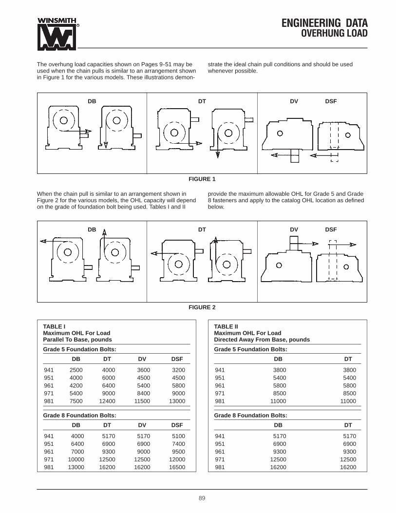
ENGINEERING DATAOVERHUNG LOAD
89
The overhung load capacities shown on Pages 9-51 may beused when the chain pulls is similar to an arrangement shownin Figure 1 for the various models. These illustrations demon-
strate the ideal chain pull conditions and should be usedwhenever possible.
DB DT DV DSF
FIGURE 1
When the chain pull is similar to an arrangement shown inFigure 2 for the various models, the OHL capacity will dependon the grade of foundation bolt being used. Tables I and II
provide the maximum allowable OHL for Grade 5 and Grade8 fasteners and apply to the catalog OHL location as definedbelow.
TABLE IMaximum OHL For Load Parallel To Base, pounds
Grade 5 Foundation Bolts:
DB DT DV DSF
941 2500 4000 3600 3200951 4000 6000 4500 4500961 4200 6400 5400 5800971 5400 9000 8400 9000981 7500 12400 11500 13000
Grade 8 Foundation Bolts:
DB DT DV DSF
941 4000 5170 5170 5100951 6400 6900 6900 7400961 7000 9300 9000 9500971 10000 12500 12500 12000981 13000 16200 16200 16500
TABLE IIMaximum OHL For Load Directed Away From Base, pounds
Grade 5 Foundation Bolts:
DB DT
941 3800 3800951 5400 5400961 5800 5800971 8500 8500981 11000 11000
Grade 8 Foundation Bolts:
DB DT
941 5170 5170951 6900 6900961 9300 9300971 12500 12500981 16200 16200
DB DT DV DSF
FIGURE 2

90
ENGINEERING DATA
GEARING INERTIA VALUES WK2 (lb in2)1
(RELATIVE TO INPUT SHAFT)
941 951 961
RATIO DB, FDB, DSF, FDSF, DB, FDB, DSF, FDSF, DB, FDB, DSF, FDSF,DT, DV FDT, FDV DSR FDSR DT, DV FDT, FDV DSR FDSR DT, DV FDT, FDV DSR FDSR
5 12.88 14.39 14.39 15.90 30.87 32.94 40.80 42.87 50.62 55.70 67.18 72.26
8 8.66 10.17 10.34 11.85 25.54 27.61 29.45 31.52 41.57 46.65 48.03 53.11
10 8.27 9.78 9.35 10.86 20.65 22.72 23.17 25.24 36.14 41.22 40.28 45.36
15 8.92 10.43 9.39 10.90 21.11 23.18 22.23 24.30 30.96 36.03 32.80 37.88
20 8.50 10.01 8.77 10.28 19.74 21.81 20.37 22.44 29.19 34.27 30.23 35.31
25 7.17 8.68 7.35 8.86 13.02 15.09 13.43 15.50 28.15 33.23 28.81 33.89
30 7.50 9.01 7.62 9.13 13.74 15.81 14.03 16.10 25.03 30.11 25.49 30.57
40 7.31 8.82 7.38 8.89 13.12 15.19 13.28 15.35 24.11 29.18 24.36 29.44
50 7.24 8.75 7.28 8.79 12.98 15.05 13.08 15.15 23.62 28.69 23.78 28.86
60 7.13 8.64 7.16 8.67 12.77 14.84 12.84 14.91 22.77 27.85 22.89 27.97
80 7.02 8.53 7.04 8.55 12.33 14.40 12.37 14.44 22.70 27.78 22.77 27.85
100 6.99 8.50 7.00 8.51 12.33 14.40 12.36 14.43 22.11 27.19 22.15 27.23
971 981
RATIO DB, FDB, DSF, FDSF, DB, FDB, DSF, FDSF,DT, DV FDT, FDV DSR FDSR DT, DV FDT, FDV DSR FDSR
5 122.33 135.13 166.23 178.93 182.43 187.93 222.83 228.33
8 85.34 98.09 102.53 115.23 118.03 123.53 133.83 139.33
10 81.27 94.03 92.23 105.03 99.70 105.23 109.83 115.33
15 61.53 74.29 66.41 79.17 79.37 84.84 83.86 89.36
20 58.11 70.87 60.85 73.61 76.67 82.14 79.20 84.70
25 52.67 65.43 54.43 67.19 57.19 62.66 58.81 64.31
30 51.52 64.28 52.74 65.50 55.04 60.51 56.16 61.66
40 52.25 65.01 52.93 65.69 55.78 61.25 56.41 61.91
50 51.72 64.48 52.16 64.92 54.16 59.63 54.56 60.06
60 51.35 64.11 51.65 64.41 56.42 61.89 56.70 62.20
80 50.33 63.09 50.50 63.26 46.13 51.60 46.29 51.79
100 49.98 62.74 50.09 62.85 45.36 50.83 45.46 50.96
1. To convert to lb-in-sec2, divide by 386.1.

91
NOTESWINSMITH
11(1'-----

NOTES
92
WINSMITH
-----lIir

NOTES
93
WINSMITH
11(1'-----

NOTES
94
WINSMITH
-----lIir

NOTES
95
WINSMITH
11(1'-----
96
TERMS AND CONDITIONS
GENERAL TERMS AND CONDITIONS OF SALESFor construction purposes be sure to obtain certified dimension sheets or drawings. Although wetake every precaution to include accurate data in our catalog, we cannot guarantee such accuracy. If performance guarantees are required, they should be obtained in writing from the home office.Full consideration will be given to such requests by the Winsmith Engineering Department whencomplete details are given of the proposed installation.
The recipient of this offer is herein called buyer and Peerless-Winsmith, Inc. is herein called seller.The term product shall include, without limitation, goods, services, work and data, expressly orimpliedly delivered hereunder and any part thereof.
1. CONTROLLING TERMSThe parties agree that there are no understandings, agreements or representations, express orimplied, not specified herein, respecting this offer or sale, and that this instrument contains theentire agreement between Seller and Buyer. No course of prior dealing and no usage of the tradeshall be relevant to supplement or to explain terms used in this agreement. All sales are expresslylimited to, and the rights and liabilities of the parties shall be governed exclusively by, the termsand conditions herein. In the event any purchase order or offer from Buyer states terms additionalto or different from those set forth herein, this document shall be deemed a notice of objection tosuch additional or different terms and a rejection thereof. Any acknowledgement or shipment ofproduct by Seller to Buyer subsequent to Seller’s receipt of a purchase order or offer from Buyershall not be deemed to be an acceptance by Seller of an offer to contract on the basis of anyBuyer’s terms and conditions. Issuance of a purchase order or acceptance by Buyer of productsshall be conclusive evidence of Buyer’s acceptance of terms and conditions set forth herein as thesole controlling terms and conditions of the contract between Seller and Buyer.
2. FORCE MAJEURThis order is accepted subject to delays due to conditions or forces beyond Seller’s control including, but not limited to strikes, work stoppages, break down, fires, accidents, contingenciesof transportation, storage or delivery, civil disturbances, shortage of labor and acts of God.
3. CREDITBuyer agrees to comply with the credit terms and accept deliveries as indicated; upon violation ordefault by Buyer, or upon bankruptcy or insolvency of Buyer, or by reason of the insecurity ofSeller as to the ultimate collectibility of the purchase price as determined by Seller in its sole andunfettered discretion, Seller may, without notice to Buyer, delay or postpone the delivery of theProducts; and Seller, at its option, is authorized to change the terms of payment to payment in fullin advance of shipment of the entire undelivered balance of said Products. In the event of defaultby Buyer in the payment of the purchase price or otherwise, Seller after demand, may sell anyundelivered Products on hand for the account of Buyer and apply such proceeds as a creditagainst the contract purchase price, and Buyer agrees to pay balance then due to Seller on demand.Such balance shall bear interest at the highest legal contract rate from the date of demand. Buyeragrees to pay all expenses, including but not limited to, storage and shipment costs, court costs,attorney’s fees and other expenses of litigation or preparation therefore, resulting from any defaultby Buyer in any of the terms thereof. Should Buyer default hereunder prior to the manufacture of allProducts ordered hereunder, Buyer agrees to pay as liquidated damages the contract price for suchunproduced or partially produced Products, less Seller’s then unexpended standard costs for mate-rials, direct labor and variable overhead with respect to the Products as in effect at the time ofdefault. Certification of such standard costs by Seller’s independent public accountants shall beconclusive on the parties hereto.
4. CHANGESOrders arising hereunder may be amended by written Change Order signed by the parties, settingforth the particular changes to be made and the effect of such changes on the price and time ofdelivery. A charge will be made for changes in drawings and/or specifications after Buyer andSeller have previously agreed upon same. The total charge for such change will include orderrepossessing costs, additional material and labor costs. Seller will advise the total charge for suchchanges after receipt of written authorization or direction for such changes. In the event thechanges are required as a result of an error on the part of the Seller, no charge will be made.
5. FAIR LABOR STANDARDS ACTSeller hereby certifies that the Products covered by this order were produced in compliance with theFair Labor Standards Act of 1938, as amended, and of regulations and orders issued thereunder.
6. TAXESAll applicable taxes of every kind or nature now or hereafter assessed which are or may becomeeffective before this order is completed may be added to the invoice price.
7. BUYER’S REPRESENTATIONS AND INDEMNITYBuyer represents and warrants that all trademarks, copyright materials, and patents submitted inconnection with this order and that the use thereof in accordance with this order will not violateany federal, state or municipal law or regulation, and Buyer agrees to indemnify and hold harmlessSeller, its agents, successors and assigns against any suits, loss, claim, demand, liabilities, costsand expenses (including attorneys’ fees) arising out of any breach or alleged breach hereof.
8. TERMSAll Sales are made F.O.B. Seller’s plant, unless otherwise specified on the face of the Seller’sacknowledgement. Payment terms are net 30 days unless otherwise specified on the face of theSeller’s acknowledgement. Delivery of all or any part of the Products to a carrier for shipment toBuyer or to a consignee designated by Buyer shall constitute delivery to Buyer and shall pass andvest title to and risk of loss of such goods to Buyer in the event of loss or damage to Products afterdelivery to a carrier. Seller will, upon request of Buyer, assist in filing claims against the carrier.
REV. 12/99
9. CANCELLATION-SUSPENSIONOrders for Products received by Seller are accepted subject to the understanding that orders maybe cancelled by Seller because of Seller’s inability to obtain all or part of the materials necessary tocomplete the order at prices in effect on the date hereof or by reason of other causes beyond itsreasonable control. Cancellation or suspension of orders may be made only upon Sellers writtenapproval. A charge will be made for cancellations and/or suspensions after Buyer and Seller havepreviously agreed upon same. Seller will advise the total charge for such cancellations and/or suspensions. Buyer agrees to pay such charges, including but not limited to, storage and ship-ment costs, costs of producing non-standard components, costs of purchasing non-returnablematerials, cancellation costs imposed on the Seller by its suppliers, engineering costs and anyother costs resulting from cancellation and/or suspension of orders by the Buyer. Certification ofsuch costs by Seller’s independent public accountants shall be conclusive on the parties hereto.
10. TOOLS, DIES AND MOLDSAny and all equipment, including tools, jigs, dies, plates, molds, fixtures, materials, equipment,drawings, designs and other information, which Seller uses, constructs or acquires for Buyer forthe purpose of filling this order shall be and remain Seller’s property.
11. DELIVERYBuyer agrees to accept delivery of all goods included in this order within the time specified on theface hereof. No extension of the delivery period shall relieve Buyer from the obligation to acceptthe goods included in this order. Partial shipment of goods will be made by Seller when ready andinvoiced.
12. CLAIMS OR RETURNSAll claims must be made in writing and delivered to Seller within ten (10) days after receipt of thegoods and must be accompanied by Seller’s packing list and freight bill. Failure of Buyer to makesuch claims within ten (10) days will constitute a waiver by Buyer or such claims.
In the event of the receipt of notice of such claims, Seller agrees to forward definitive shippinginstructions to Buyer or to send a representative of Seller to Buyer’s facilities to review shipmentand make any necessary adjustments. No return of the goods pursuant to this paragraph shall bemade for any purpose without the prior written consent of Seller. Transportation charges on allgoods returned after receipt of Seller’s Authorization must be prepaid. Any goods returned byBuyer without Seller’s consent shall be held for the account of Buyer.
13. CHARGESPast due accounts are subject to late payment charges of 11⁄2% per month or such lesseramounts are legally permissible.
14. SOLVENCYBuyer, by these presents and the acceptance of the Products, represents and warrants that Buyeris solvent and able to pay for the Products in accordance with the terms of sale.
15. WARRANTIESThe Products manufactured by Seller are warranted by Seller as follows: (a) Seller has the right tosell the Products, (b) Buyer and its customers shall have the right to enjoy the Products free ofclaims of third persons against the Seller, and (c) the Products shall be free from manufacturingdefects in material and workmanship under normal use and service for a period of twenty-four (24)months from date of shipment. This warranty does not apply to any Products which have been tam-pered with, improperly stored, exposed to heat or moisture or otherwise subject to misuse or abuse.
THE FOREGOING WARRANTIES ARE IN LIEU OF ALL OTHER WARRANTIES EXPRESS OR IMPLIED INCLUDING, WITHOUT LIMITATION, WARRANTIES OR MERCHANTABILITY ANDFITNESS FOR ANY PARTICULAR PURPOSE.
Except as otherwise agreed in writing in each specific instance, the obligation of Seller is limited:(i) in the case of any material breach of the warranties set forth in subparagraphs (a) and (b)above, to the reimbursement of the price paid by Buyer or its customer for such Products: and (ii)in the case of any breach of the warranty set forth in subparagraph (c) above, to any of the follow-ing (at Seller’s option): refund of the purchase price or repair or replacement of any such defectiveProduct without charge other than for transportation.
SELLER SHALL NOT IN ANY EVENT BE LIABLE FOR INCIDENTAL, CONSEQUENTIAL OR SPECIALDAMAGES resulting from any use or failure of the Products, including, without limitation, liabilityfor loss of time to, profits or products of, Buyer or the user for any labor or any other expense,damage or loss occasioned by any such defect.
Simultaneously with the delivery by Dealer to its customer of any Products purchased by Buyerfrom Seller, Buyer shall deliver therewith such printed warranties and disclaimers of warranties inrespect to said merchandise as shall be furnished by Seller to Buyer or packed with said merchandise for that purpose. Buyer further agrees that the obligations of Seller to Buyer withrespect to all Products purchased by Buyer from Seller shall be as hereinabove set forth. In noevent shall Seller’s obligation for breach of warranty exceed the purchase price of product.
16. ARBITRATIONAny controversy arising under, or in any way related to this order or the subject matter hereof shallbe settled by arbitration by three disinterested arbitrators in the City and State of New York, andunder the laws of said State, in accordance with rules of the American Arbitration Association thenobtaining. All costs of such arbitration, and any proceedings directly or indirectly related thereto,including reasonable attorney’s fees, shall be paid by the party against whom the arbitrators shallrender their award or as otherwise directed by the arbitrators.
17. LAWThe contract shall be governed and construed under the State where the products are manufactured.

WINSMITH®’s Regional Service Centers, shownon the map, can provide prompt solutions toyour unique delivery requirements. EachService Center is fully stocked with the necessary components and assemblies to provide a wide variety of finished units with the same high quality that you expect fromWINSMITH’s manufacturing plants.
6/03
WINSMITH DISTRICT OFFICES
®
ALABAMASee Georgia
CALIFORNIALos Angeles (Buena Park)� Service Center
562/404-0304FAX 562/404-8060
San Francisco(Brentwood)
925/634-2818FAX 925/634-4314
COLORADOLakewood
303/205-1922FAX 303/205-1477
FLORIDAClermont
352/243-7517FAX 352/243-3518
GEORGIAAtlanta (Alpharetta)
770/772-7270FAX 770/772-7277
ILLINOISChicago (Downers Grove)� Service Center
630/629-3434FAX 630/629-1010
INDIANASee Cincinnati, OH
KANSASKansas City
816/524-2010FAX 816/524-2944
KENTUCKYSee Cincinnati, OH
MASSACHUSETTSSee Rhode Island
MICHIGANDetroit
734/878-9050FAX 734/878-9051
MINNESOTAPlymouth
763/559-1021FAX 763/559-6552
MISSOURIKansas City
816/524-2010FAX 816/524-2944
St. Louis314/576-1488FAX 314/576-0433
NEW JERSEYSee Philadelphia, PA
NEW YORKSpringville (Factory)
Peerless-Winsmith716/592-9310FAX 716/592-9546
NEW YORK (cont.)New York CitySee Philadelphia, PA
NORTH CAROLINASee Georgia
OHIOCleveland (Wickliffe)
440/585-2121FAX 440/585-2122
Cincinnati513/791-5009FAX 513/791-4717
OKLAHOMASee Texas
OREGONPortland� Service Center
503/227-6638FAX 503/227-5413
PENNSYLVANIAHarrisburg/Philadelphia
Sales Office315/684-3553FAX 315/684-3562
Western PASales Office716/751-0134FAX 716/751-4051
RHODE ISLANDWarwick
401/732-4570FAX 401/732-4583
SOUTH CAROLINASee Georgia
TENNESSEESee Georgia
TEXASDallas/Houston
1-800/383-5918FAX 877/867-5386
UTAH See Colorado
VIRGINIAVinton
540/890-7756FAX 540/890-7855
WISCONSINCedarburg
414/375-4465FAX 414/375-4175
BRITISH COLUMBIASee Springville, NY
ONTARIOToronto (Mississauga)� Service Center
905/828-1222FAX 905/828-1225
WINSMITH SERVICE CENTERS
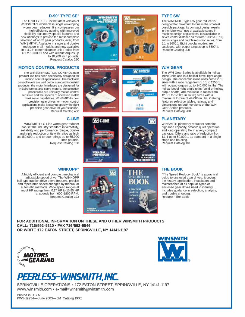
FOR ADDITIONAL INFORMATION ON THESE AND OTHER WINSMITH PRODUCTS CALL: 716/592-9310 • FAX 716/592-9546OR WRITE 172 EATON STREET, SPRINGVILLE, NY 14141-1197
SPRINGVILLE OPERATIONS • 172 EATON STREET, SPRINGVILLE, NY 14141-1197www.winsmith.com • [email protected] in U.S.A.PWS-19234—June 2003—5M Catalog 190I
®
D-90® TYPE SE®
The D-90 TYPE SE is the latest version ofWINSMITH’s world class single enveloping
worm gear reducers. It encompasses our high efficiency gearing with improved
flexibility plus many special features and new offerings to provide the most completeselection of worm gear products, ever, fromWINSMITH®. Available in single and double
reduction in all models and now available in a 4.25" center distance unit. Ratios from4:1 to 10,000:1 and with output torques up
to 10,700 inch pounds.Request Catalog 290
MOTION CONTROL PRODUCTSThe WINSMITH MOTION CONTROL gear
product line has been specifically designed formotion control applications. The backlash
control levels are well below standard industrialproducts, the motor interfaces are designed forNEMA frames and servo motors, the selection
procedures are uniquely motion controlsensitive and the speeds of operation match
most servo capabilities. WINSMITH’s newprecision gear drives for motion control
applications make it easy to specify the rightprecision gear drive for your situation.
Request Catalog 400
C-LINEWINSMITH’s C-Line worm gear reducer
has set the industry standard in versatility,reliability and performance. Single, double
and triple reduction units with ratios as highas 180,000:1 and torque ratings up to 65,000
inch pounds.Request Catalog 100
WINKOPP®
A highly efficient and compact mechanicaladjustable speed drive. The WINKOPP
ball-type traction drive offers frequent, preciseand repeatable speed changes by manual or
automatic methods. Wide speed ranges atinput HP ratings from 0.17 HP to 16.85 HP
at speeds from 600-1800 RPM. Request Catalog 323
TYPE SWThe WINSMITH Type SW gear reducer isdesigned for maximum torque in the smallestpossible package. Its compact design results in the “size wise” use of available space inmachine design applications. It is available inseven center distance sizes from 1.33" to 3.75",and in single and double reduction ratios, from5:1 to 3600:1. Eight popular models arecataloged, with output torques up to 6500"#. Request Catalog 300
W/H GEAR The W/H Gear Series is available in helicalinline units and in a helical-bevel right angledesign. The concentric inline units come in 10sizes with a ratio range from 1.6:1 to 1250:1with output torques up to 140,000 in. lbs. Thehelical-bevel right angle units (solid or hollowoutput shafts) are available in ratios from12.5:1 to 1250:1 in six (6) sizes with amaximum torque of 49,000 in. lbs. Catalogfeatures selection tables, ratings, anddimensions on both versions of the W/HGear Series products. Request Catalog 200
PLANETARYWINSMITH planetary reducers combine high load capacity, smooth quiet operationand long operating life in a very compactpackage. Offers any ratio of reduction from1.1:1 up to 50,000:1 as standard in a singlestage and housing.Request Catalog 110
THE BOOK‘‘The Speed Reducer Book’’ is a practicalguide to enclosed gear drives. It covers the history, application, installation andmaintenance of all popular types of enclosed gear drives used in industry.Includes guidance in selection, analysis, and trouble shooting.Request ‘‘The Book’’