
CZM Soc Trang, Vietnam Design of Breakwaters - … · Detailed Design of Breakwaters 47 Pages, 14...
61
August 2011 CZM Soc Trang, Vietnam Design of Breakwaters
-
Upload
nguyentuyen -
Category
Documents
-
view
214 -
download
0
Transcript of CZM Soc Trang, Vietnam Design of Breakwaters - … · Detailed Design of Breakwaters 47 Pages, 14...

Au
gu
st
2011
CZM Soc Trang, Vietnam Design of Breakwaters

Page 2
Management of Natural Resources in the Coastal Zone of Soc Trang Province, Vietnam
Detailed Design of Breakwaters
47 Pages, 14 Attachments Project: Management of Natural Resources in the Coastal Zone
of Soc Trang Province, Vietnam 134 Tran Hung Dao Street Soc Trang City, Viet Nam
Client: Deutsche Gesellschaft für Internationale Zusammenarbeit (GIZ) GmbH
Dag-Hammarskjöld-Weg 1-5 65760 Eschborn, Germany
Design: von Lieberman GmbH Ruhrstraße 57 22761 Hamburg, Germany Tel.: 040 / 500 993-0 Fax: 040 / 500 993-33
Contact Person: Dipl.-Ing. Thorsten Albers (Expert River and Coastal Engineering)
Project Number: 13713-01 Hamburg, 23.08.2011
DAP-PL-3797.00
Die Anfertigung von Kopien und die Publikation von Textauszügen sind nur mit der ausdrücklichen Zustimmung des Auftraggebers erlaubt.

Page 3
TABLE OF CONTENTS Page
1 INTRODUCTION ................................................................................................ 8
1.1 Background ......................................................................................................... 8 1.2 Scope of work ..................................................................................................... 9
2 BOUNDARY CONDITIONS ............................................................................. 11
2.1 Waves ............................................................................................................... 11 2.2 Current velocities .............................................................................................. 12 2.3 Wind ................................................................................................................. 12 2.4 Soil.................................................................................................................... 12
3 PRELIMINARY DESGIN .................................................................................. 14
4 MATERIAL CHARACTERISTICS OF BAMBOO ............................................. 16
4.1 Literature review ............................................................................................... 16 4.2 Material parameters .......................................................................................... 17 4.3 Fracture behaviour ............................................................................................ 18
5 STATIC DESIGN .............................................................................................. 19
5.1 Current- and wave-induced loads ..................................................................... 19 5.1.1 Single piles ....................................................................................................... 19 5.1.2 Wall .................................................................................................................. 20 5.2 Breaking waves................................................................................................. 21 5.3 Impacts ............................................................................................................. 22 5.4 Man weight ....................................................................................................... 22 5.5 Wind load .......................................................................................................... 22
6 GEOTECHNICAL DESIGN AND PROOF OF STRUCTURAL SAFETY .......... 24
6.1 Vertical forces ................................................................................................... 24 6.2 Horizontal forces ............................................................................................... 26
7 PLANS ............................................................................................................. 32
7.1 Site maps and description ................................................................................. 32 7.2 Front views, cross sections and top views......................................................... 32 7.3 Details ............................................................................................................... 33
8 CONSTRUCTION PROGRESS ....................................................................... 34
8.1 Preparation and site facilities ............................................................................ 34 8.2 Installation ......................................................................................................... 34 8.3 Construction sequence ..................................................................................... 37 8.4 Drainage system ............................................................................................... 37
9 AMOUNT OF MATERIAL ................................................................................ 39
10 CONSTRUCTION SUPERVISION ................................................................... 41
10.1 Tensile tests ...................................................................................................... 41

Page 4
11 OUTLOOK ....................................................................................................... 44
12 REFERENCES ................................................................................................. 45
13 ATTACHMENTS .............................................................................................. 47

Page 5
LIST OF FIGURES
Figure 1: Grain size distribution at the coast of Vinh Tan ................................................. 13
Figure 2: Recommended combination of bamboo breakwater and bamboo fences ......... 15
Figure 3: Lateral view of the bamboo fences and the bamboo breakwater (scheme);
viewing direction: north-east ............................................................................ 15
Figure 4: Calculational cross section of a bamboo pile .................................................... 18
Figure 5: Computed non-breaking wave forces on vertical walls ..................................... 21
Figure 6: Illustration of the subgrade reaction method incl. static system, bending
line, horizontal soil pressure and bending moment .......................................... 26
Figure 7: Distribution of the momentum into a force couple ............................................. 29
Figure 8: Joint made with rattan strips (DUNKELBERG, 2000)............................................ 33
Figure 9: Sharpened round timber with a handle bar for the preparation of the instal-
lation (left), head ram for the installation of the vertical piles ............................ 35
Figure 10: Installation of vertical piles using a pile-driving machine or a dredger bucket.. 35
Figure 11: Steel lance for the installation of the vertical piles with water pressure ........... 36
Figure 12: Drainage network in a main field ..................................................................... 38
Figure 13: Cross-section of main and minor ditches of the drainage system ................... 38
Figure 14: Setup of the tensile tests (2 options of abutment) ........................................... 42
Figure 15: Tension belt including belt spanner (left), crane weigher (right) ...................... 43

Page 6
LIST OF TABLES
Table 1: Simulated waves at Vinh Tan during southwest and northeast monsoon ........... 11
Table 2: Comparison of test results ................................................................................. 17
Table 3: Material parameters applied in the design process ............................................ 17
Table 4: Calculation of Mmax, zM, max σ, and zσ for the different loading cases ................ 28
Table 5: Estimated amount of material for the breakwater and the bamboo fence ........... 39

Page 7
LIST OF ATTACHMENTS
Attachment 1: Site map with background
Attachment 2: Site map without background
Attachment 3: Site map with control points
Attachment 4: Cross-section breakwater/longshore fence
Attachment 5: Side view breakwater/longshore fence
Attachment 6: Top view breakwater/longshore fence
Attachment 7: Cross-section cross-shore fence
Attachment 8: Side view cross-shore fence
Attachment 9: Top view cross-shore fence
Attachment 10: Top view connection longshore/cross-shore fence
Attachment 11: Top view connection cross-shore fence/revetment
Attachment 12: Side view cross-shore fence incl. connection to revetment
Attachment 13: Details cross-section breakwater/longshore fence and side view breakwa-ter/longshore fence
Attachment 14: Details cross-section cross-shore fence and side view cross-shore fence

Page 8
1 INTRODUCTION
1.1 Background
Along the coastline of Soc Trang Province, Viet Nam, dynamic processes of accretion and
erosion occur influenced by interactions between:
the discharge regime of the Mekong Delta,
the tidal regime of the South China Sea and
the monsoon weather patterns of Southeast Asia.
Coastal erosion and accretion are complex processes depending on various influences. Key
elements are the sediment transport under the influence of currents and waves, the overall
dynamics of beaches in a coastal section and anthropogenic impacts.
Due to its vectorial character, the sediment transport at the coast may be divided into:
cross-shore sediment transport (on-/offshore transport)
longshore sediment transport.
Coastal cross-shore sediment transport induces short-term morphologic changes of sedi-
ments, e.g. during storm events. Coastal longshore transport causes long-term morphologic
changes of a coastal section.
In some areas, such as the focus area of Vinh Tan Commune, severe erosion endangers the
dyke and consequently the people and farmland located behind the dyke.
The morphodynamics in the focus area of Vinh Tan have been investigated and analysed in a
study executed by the Hamburg University of Technology in 2009 and 2010 (ALBERS & VON
LIEBERMAN, 2011).
In collaboration with the Southern Institute of Water Resources Research (SIWRR), available
data with relevance to the coast of Soc Trang were researched and analysed. Although data
on the bathymetry, water levels, river discharges and sediment freights were available, essen-
tial data about the erosion site, especially about the wave climate, were missing. Therefore,
measurement campaigns were carried out to close this gap and build the foundation for so-
phisticated and effective erosion protection measures. Over the course of three measurement
campaigns, information about currents, waves, sediment concentrations and the bathymetry

Page 9
were recorded. The field measurements covered different seasons including the northeast and
southwest monsoons.
The wave measurements showed a clear dependency on the monsoon season. Recorded
currents show a long-shore component due to the approach of the tidal wave along the South
Vietnamese coast. These currents are increased by the northeast monsoon.
The available and generated databases were used to set-up, calibrate and verify different nu-
merical models. Shoreline changes were computed considering various erosion protection
measures. Besides conventional techniques, an alternative approach using local materials
was investigated.
Along the southeast coast of Viet Nam, natural erosion and accretion alternate across different
sections. The exposed coastline is affected by long-shore flood currents, off-shore directed
ebb currents and waves. Periods with increased wave activity will increase the erosion rate,
whereas periods with decreased wave activity may even lead to accretion. During the north-
east monsoon, lower sediment supply from the Mekong, stronger currents and higher waves
increase erosion. In places where the overgrown foreland disappeared, severe erosion can
endanger the stability of the dykes over time, even after periods of temporary accretion.
1.2 Scope of work
All coastal protection or erosion protection measures – except from beach nourishment –
cause downdrift erosion. Hard coastal protection measures should only be applied if human
lives or larger monetary values are endangered. In general additional nourishment is neces-
sary to reduce the negative effects of the installed structures. Coastal erosion protection has to
be designed carefully to secure the desired effects and minimize downdrift erosion. A close to
nature solution is worthwhile.
In the current and erosion modelling survey, different arrangements and designs of erosion
protection measures were investigated by means of numerical and physical modelling. In addi-
tion to the application of conventional breakwaters, adapted approaches using local materials
were investigated. In conclusion, recommendations for erosion protection measures were giv-
en based on the model results, the field measurements and a cost analysis.
The use of local materials like bamboo has many advantages based on its strength, availability
and costs. Using a breakwater made of bamboo the desired wave transmission can be

Page 10
achieved. Therefore, the construction of bamboo breakwaters is recommended. Furthermore,
the costs of this solution are low, compared to the other options.
All constructions designed in this report (breakwater, longshore and cross-shore fences) have
to be made from bamboo.
Before constructing the recommended and agreed upon solution, a practical plan has to be
provided. This document provides detailed plans of the construction containing all accurate
positions, dimensions and construction details in the form of site maps, cross sections and top
views. All static and geotechnical verifications are done. For the construction phase, several
measures of quality control, e.g. experimental identification of the breaking force of the bam-
boo and verification of a sound installation of the bamboo piles, are proposed.
This document provides the product specifications for the construction. Mass and cost calcula-
tions included in the submitted quotations must be verified based on local prices. During the
construction, supervision of the tensile tests of the bamboo piles must be carried out to quanti-
fy the breaking forces of single piles and pile groups. The depth of embedment of the piles
must be controlled as well as the construction materials. A detailed documentation of the con-
struction phase is essential.
The construction of the bamboo breakwater and bamboo fences in Vinh Tan serves as a pilot
project for erosion protection and mangrove rehabilitation in erosion sites, which will also be
used to gain knowledge for future application and optimisation through detailed documentation
and monitoring.

Page 11
2 BOUNDARY CONDITIONS
ALBERS & VON LIEBERMAN (2011) provide a detailed description of the investigation area, its
hydrology and morphodynamics. Here, only the relevant loads are summarised. The values
were derived from available data and time series, field measurements and numerical model-
ling. For details see ALBERS & VON LIEBERMAN (2011).
2.1 Waves
The wave model was calibrated and verified using wind data, data from available gauges and
data from field measurements. Different scenarios were simulated. In one scenario, storm
conditions during the southwest monsoon were simulated with peak wind velocities of 16 m/s.
In that scenario, significant wave heights of 0.58 m were predicted at Vinh Tan. The average
wave direction at Vinh Tan is from south-southwest during that event.
Another model run simulated waves during the northeast monsoon season with peak wind
velocities of 25 m/s. For the coast at Vinh Tan, significant wave heights of 0.63 m were com-
puted. Although the wind velocity is higher than in the southwest monsoon scenario, the
waves are not significantly higher, because Vinh Tan is located in the wave shadow of the
Mekong Delta with its sandbanks.
The wave parameters for different scenarios are summarised in Table 1.
Table 1: Simulated waves at Vinh Tan during the southwest and northeast monsoon
Simulated
Scenario Wind direction [°]
Wind speed [m/s]
Peak peri-od TP [s]
Sign. wave height HS [m]
1a SW 16.28 6.04 0.58
1b WSW 18.90 6.04 0.58
1c W 15.75 9.70 0.54
2a NNE 20.53 5.50 0.52
2b NE 25.24 5.50 0.63
For the design of the breakwaters, a significant wave height of 0.65 m and a peak period of
5.5 s can be taken as a basis. Waves may approach from different angles. The maximum
wave height is calculated as
Page 12
based on the theory of LONGUET-HIGGINS (cf. EAK, 2002) assuming an event with 1000
waves.
The maximum wave height can only be achieved at respective water depths, taking wave
breaking into account.
2.2 Current velocities
The current velocities in the investigation area are mainly influenced by tides. The tidal range
is 3.50 m leading to water depths up to 1.50 m at tidal high water at the position of the project-
ed breakwater. The results of both the field measurements and the numerical modelling were
used to define the current parameters.
During the northeast monsoon season in January 2010 the stationary installed AWAC record-
ed current velocities between 0.10 m/s and 0.60 m/s during floods. The peaks in current veloc-
ity during ebb tide were less pronounced, between 0.10 m/s and 0.40 m/s.
The mobile ADCP surveys showed seaward currents during ebb tide of around 0.40 m/s and
maximum long-shore currents during flood tide of approximately 1.00 m/s, whereas the largest
values were measured further offshore.
The hydrodynamic model computed current velocities between 0.20 and 0.50 m/s in the near-
shore area. Therefore, the model results and the current measurements in the focus area
show a good correlation.
For the design of the breakwaters a current velocity of 0.50 m/s is assumed.
2.3 Wind
One possible loading case for the design of the bamboo breakwater is when high wind veloci-
ties occur during low water and full exposure of the breakwater. For this case a design wind
velocity of 25 m/s according to scenario 2b (cf. chapter 2.1) based on available data sets is
assumed.
2.4 Soil
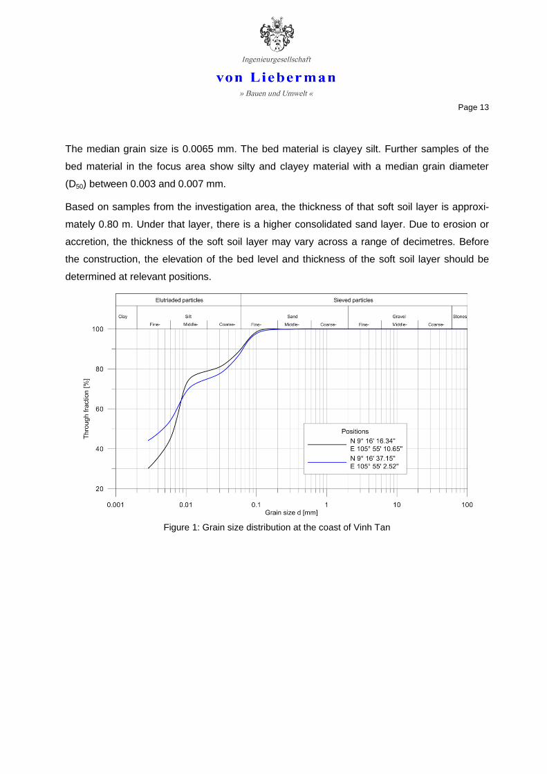
Samples of bed material were analysed in a geotechnical laboratory. Figure 1 shows the grain
size distribution of two bed samples on the coast of Vinh Tan.
Page 13
The median grain size is 0.0065 mm. The bed material is clayey silt. Further samples of the
bed material in the focus area show silty and clayey material with a median grain diameter
(D50) between 0.003 and 0.007 mm.
Based on samples from the investigation area, the thickness of that soft soil layer is approxi-
mately 0.80 m. Under that layer, there is a higher consolidated sand layer. Due to erosion or
accretion, the thickness of the soft soil layer may vary across a range of decimetres. Before
the construction, the elevation of the bed level and thickness of the soft soil layer should be
determined at relevant positions.
Figure 1: Grain size distribution at the coast of Vinh Tan

Page 14
3 PRELIMINARY DESGIN
The aim of the structural measures is to reduce erosion and to increase accretion. Negative
effects like downdrift erosion must be avoided as much as possible.
At the endangered dyke in the focus area, a section of approximately 200 m has to be protect-
ed. Different arrangements of breakwaters were tested based on various simulations (ALBERS
& VON LIEBERMAN, 2011).
The construction of breakwaters always leads to downdrift erosion. This effect is minimized if
one breakwater is installed with a length of 100 m at a distance of 50 m from the idealized
shoreline. The transmission coefficient should be around 0.50. The desired wave transmission
can be achieved with a breakwater made of bamboo. The results of the respective physical
modelling can be found in ALBERS & VON LIEBERMAN (2011). The application of local materials
like bamboo has many advantages due to its strength, availability and costs. Therefore, the
construction of the bamboo fence is recommended. Furthermore, the costs of this solution are
low compared to the other options.
If the gaps between the eroded floodplains at the endangered dyke are closed, the wave en-
ergy will dissipate on the newly developed floodplain and the dyke will be protected from ero-
sion. Closing the gaps will create a close to nature situation, with no significant resulting
downdrift erosion. Therefore, a chequered arrangement of bamboo fences at the dyke is rec-
ommended in combination with a bamboo breakwater parallel to the coast.
Figure 2 shows the accordant arrangement. A sound monitoring will lead to detailed infor-
mation about the effectiveness of both measures.
The length of the bamboo fences indicated in Figure 2 adds up to approximately 400 m. The
length of the bamboo breakwater is 100 m.
Figure 3 shows diagrams of the lateral views of the bamboo fences and the bamboo breakwa-
ter.

Page 15
Figure 2: Recommended combination of bamboo breakwater and bamboo fences
Figure 3: Lateral view of the bamboo fences and the bamboo breakwater (scheme); viewing direc-
tion: north-east

Page 16
4 MATERIAL CHARACTERISTICS OF BAMBOO
It is known that the mechanical properties of solid timber are affected by climatic and soil con-
ditions, location, age, time of felling, moisture content etc. Furthermore, there are considerable
variations over the length of the trunk or its cross-section. The strength of the timber also de-
pends on the directions of the forces (parallel or perpendicular to the direction of the fibres).
The variation in strength values of bamboo as a hollow cylinder with different material thick-
nesses within the cane wall and the nodal diaphragms perpendicular to this wall, is almost
even larger. A precise picture of these values may only be obtained through data from bamboo
strips and bamboo canes. Several sources were compiled and compared before the detailed
design of the breakwaters, in the context of a literature review.
The space in between the two rows of bamboo piles is filled with available brushwood. The
brushwood must calm the currents and dissipate wave energy and has to be permeable
enough to let fine sediment particles enter the fence fields.
4.1 Literature review
To evaluate and compare the material characteristics of bamboo, its origin, age, humidity con-
tent and the diameter of the tube are of high importance. Comparing results of various investi-
gations on the properties of bamboo, a certain fluctuation in results is evident, although all
tests were conducted with the same species of bamboo (guadua angustifolia).
The results of different studies can be found in relevant literature:
ATROPS, 1969
HIDALGO, 1974
JANSSEN, 1981
JANSSEN, 1990
LINDEMANN & STEFFENS, 2000
AICHER, 2000
DUNKELBERG, 2000
Page 17
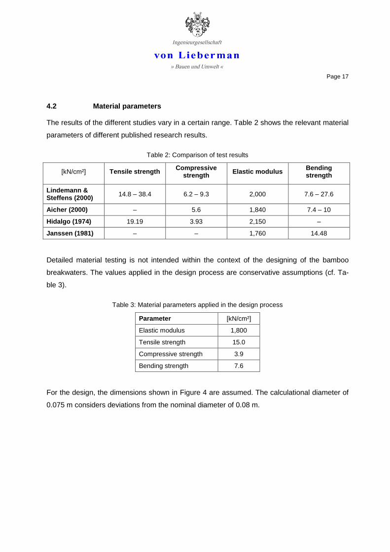
4.2 Material parameters
The results of the different studies vary in a certain range. Table 2 shows the relevant material
parameters of different published research results.
Table 2: Comparison of test results
[kN/cm²] Tensile strength Compressive
strength Elastic modulus
Bending strength
Lindemann & Steffens (2000)
14.8 – 38.4 6.2 – 9.3 2,000 7.6 – 27.6
Aicher (2000) – 5.6 1,840 7.4 – 10
Hidalgo (1974) 19.19 3.93 2,150 –
Janssen (1981) – – 1,760 14.48
Detailed material testing is not intended within the context of the designing of the bamboo
breakwaters. The values applied in the design process are conservative assumptions (cf. Ta-
ble 3).
Table 3: Material parameters applied in the design process
Parameter [kN/cm²]
Elastic modulus 1,800
Tensile strength 15.0
Compressive strength 3.9
Bending strength 7.6
For the design, the dimensions shown in Figure 4 are assumed. The calculational diameter of
0.075 m considers deviations from the nominal diameter of 0.08 m.
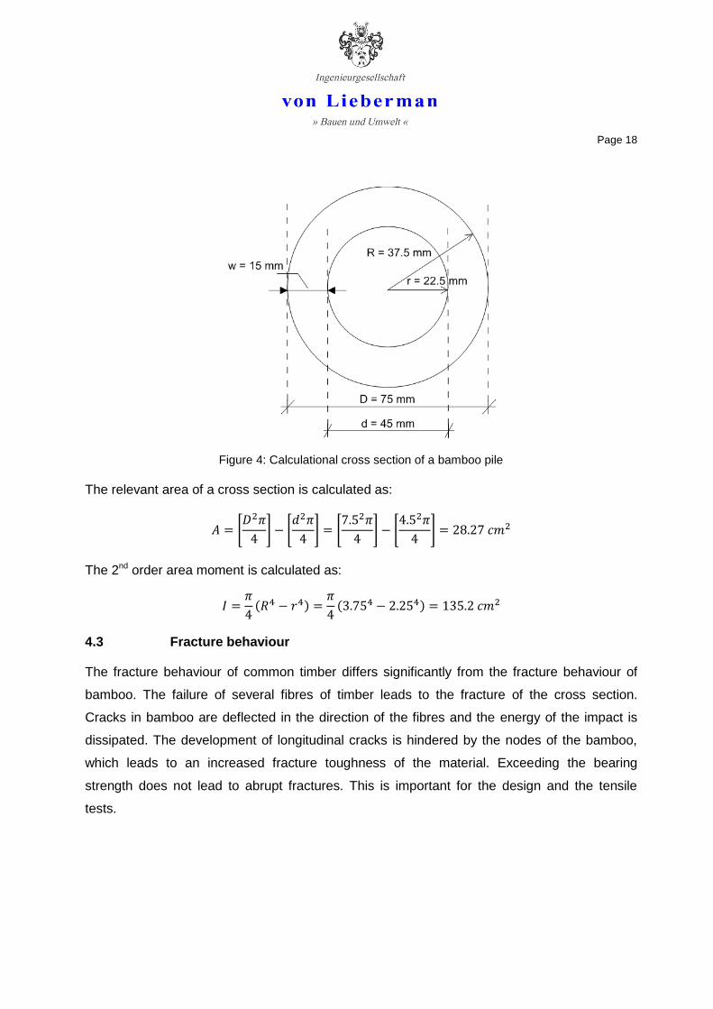
Page 18
Figure 4: Calculational cross section of a bamboo pile
The relevant area of a cross section is calculated as:
[
] [
] [
] [
]
The 2nd order area moment is calculated as:
( )
( )
4.3 Fracture behaviour
The fracture behaviour of common timber differs significantly from the fracture behaviour of
bamboo. The failure of several fibres of timber leads to the fracture of the cross section.
Cracks in bamboo are deflected in the direction of the fibres and the energy of the impact is
dissipated. The development of longitudinal cracks is hindered by the nodes of the bamboo,
which leads to an increased fracture toughness of the material. Exceeding the bearing
strength does not lead to abrupt fractures. This is important for the design and the tensile
tests.

Page 19
5 STATIC DESIGN
The design of the bamboo breakwater and bamboo fences is done based on available design
approaches. The breaking force is estimated based on relevant literature (cf. chapter 4). In
addition, during the construction the breaking force of several bamboo piles should be deter-
mined experimentally to confirm the assumed values. A sound installation of the piles into the
ground is essential.
5.1 Current- and wave-induced loads
5.1.1 Single piles
The front row of bamboo piles is directly loaded by currents and waves. The calculation of the
loads resulting from currents and waves is done based on the superposition method by Mori-
son, O’Brian, Johnson and Schaaf (MOJS). The current forces and acceleration forces of the
tidal current and the waves result from the following formula (EAK, 2002):
| |
Sum of current force and acceleration force [kN/m]
Current force on the pile [kN/m]
Acceleration force on the pile [kN/m]
Current resistance coefficient [-]
Inertia resistant coefficient [-]
Density of water [t/m³]
Diameter of the pile [m]
Horizontal component of current/orbital velocity [m/s]
Horizontal component of current/orbital acceleration [m/s²]
The total load on the pile is determined by solving the integral of the calculated line forces. The
different parts of the wave load are dephased. Different phases of the wave passage have to
be considered.

Page 20
Based on physical tests, the coefficients CD and CM were determined by CERC (1984) for dif-
ferent Reynolds-Numbers:
1.8
Tidal currents:
( ) ⁄
Waves:
1. Loading case: Maximum orbital velocity
⁄
2. Loading case: Maximum orbital acceleration
⁄
3. Loading case: Combination
⁄
The design load results from the tide and first loading case of the wave load and adds up to
0.03 kN/m. For a bamboo pile 1.30 m in length, the resulting force is 0.04 kN.
5.1.2 Wall
The rear row of bamboo piles is loaded by the horizontal current- and tide-induced forces
transmitted by the brushwood wall. The calculation of the resulting loads is done using the
Coastal Engineering Design and Analysis System (CEDAS) based on the approaches of
Miche-Rundgren and Sainflou. The results of the calculation are summarized in Figure 5.

Page 21
Figure 5: Computed non-breaking wave forces on vertical walls
Applying the Sainflou approach, the resulting integrated horizontal force is 20 kN per metre
width. This maximum load occurs at the crests of the waves. With a distance of 0.10 m be-
tween the vertical bamboo piles, this results in a horizontal force on each bamboo pile of 2 kN.
5.2 Breaking waves
Breaking waves can induce high compression stresses on piles in the front row above the stat-
ic water level. These “slaps” or “slams” appear for very short times (in the range of millisec-
onds) and therefore are not important for the total design. For local loads in the area of the
static water level the slamming forces need to be considered.
The slamming force results to:
= Slamming force [kN]
= Slamming coefficient [-]
= Density of the water [t/m³]
= Diameter of the pile [m]
= curling factor [-]
= maximum water level of the breaker above the static water level (app. 0.7 · Hs) [m]
= maximum horizontal component of the orbital velocity [m/s]
Page 22
The structure of the brushwood absorbs the energy resulting from slams. Therefore, the influ-
ence of breaking waves on the brushwood is neglected.
5.3 Impacts
Abnormal forces can result from the impact of floating items like flotsam or vessels. Interna-
tional standards for the certification of mobile flood protection walls assume the impact of a
300 kg item for the approval of the systems. This value is also considered as sufficient for the
static design of the bamboo constructions taking into account the boundary conditions like
water depth and external circumstances.
The maximum impact is calculated as:
A maximum velocity of the floating items of 0.3 m/s (cf. 2.2) is assumed. The flexible structure
of the construction allows for assuming a dwell time of the impact of 2 s.
5.4 Man weight
The consideration of forms of vandalism is covered with 5.3.
Additionally a man weight of 1 kN as a vertical load is assumed for each bamboo pile based
on German Standards (DIN 1055, Part 3).
5.5 Wind load
On the North Sea Coast, long and slender tree trunks are used to mark navigation channels in
the Wadden Sea. There are reported cases in which the trunks failed during storm conditions
and low water. Although these trunks are much more exposed to the wind due to their length
above ground, this loading case is proofed here.
The front row of bamboo piles is directly loaded by the dynamic wind pressure. The force on a
single bamboo pile is calculated as:
| |
If the bamboo fence is regarded as a permeable wall, the rear row of bamboo piles is loaded
by the dynamic pressure based on German Standards (DIN 1055, Part 4) and calculated as:

Page 23
⁄ ⁄
The values and are estimated based on German Standards. The result has to be divided
by the number of piles per metre to get the force on one pile per metre height. The difference
to the calculation for a single pile above results from the influence of the brushwood. With a
distance of 0.10 m between the vertical piles the resulting force on a single pile is approxi-
mately 0.04 kN.

Page 24
6 GEOTECHNICAL DESIGN AND PROOF OF STRUCTURAL SAFETY
In constructional engineering, piles with small diameters usually are designed as piles with
axial applied loads. The piles of the bamboo breakwaters are also designed to absorb momen-
tum. Therefore, horizontal loads are transferred to the ground by an elastic clamping of the
pile. Thus, the static system is a bending resistant pile backed by the surrounding soil. In prac-
tice the subgrade reaction method is accepted. It is assumed that the horizontal pressure be-
tween the pile and the soil is proportional to the horizontal displacement of the pile. The pro-
portionality factor ks (bedding modulus) can vary with the depth, whereas the well known para-
ble of Titze offers a good description of the distribution of ks (cf. ARZ ET AL., 1991).
The load bearing behaviour in the axial and horizontal directions is calculated first of all for
detached single piles. If the piles are arranged in groups they influence each other in terms of
load transmission. If the piles are arranged very close to each other, the soil between them is
distorted. Due to the lack of sustainable calculation methods for the present case, the load
bearing behaviour of those piles has to be determined by tests.
For the geotechnical design, the characteristics of the sand layer are applied. The depth of
embedment refers to the depth in the sand layer. The mud layer is assumed to be a buffer
layer that can grow and shrink due to external circumstances like increased or decreased in-
coming wave energy and that does not have load-bearing attributes. Furthermore, the mathe-
matical description of the mud layer is very uncertain.
The geotechnical design and the proof of structural safety are primarily carried out for the
bamboo breakwaters and the longshore bamboo fences. These structures dissipate the main
wave and flow energy as well as possible impacts of floating items. The diameter of the bam-
boo piles of the cross-shore fences can be chosen one size smaller due to the reduced loads.
Therefore, the most visible parts of the erosion protection will appear less massive. Further-
more, this adjustment will reduce costs.
6.1 Vertical forces
The compressive force parallel to the bamboo fibres resulting from man weight is:
Page 25
Therefore, the proof of the compressive strength of a bamboo pile due to the man load is giv-
en.
Vertical forces occur due to man weight. The jacket friction must be large enough to carry that
man weight. It is dependent on the depth of embedment. The man weight is assumed to occur
during low water, while no lift forces are effective in the opposite direction.
The depth of embedment is calculated as:
⁄
= coefficient for sand with fine grains, undrained, cohesion
= Perimeter of the bamboo pile
The loading case vertical forces due to the man weight are not significant for the depth of em-
bedment.
The lift force of a single bamboo pile during high water is 168 N and therefore significantly
smaller than the man weight.
( ) ( )
= density of water
= gravitational acceleration
(
) = volume of the displaced water
= density of bamboo
= volume of the displaced water
Thus, the depth of embedment resulting from the man weight is large enough to activate the
jacket friction effective in the opposite direction of the lift force. The lift forces of the horizontal
bamboo bars and the brushwood are distributed over several vertical piles and can be ne-
glected because the depth of embedment will have to be significantly larger than 0.18 m due
to the horizontal forces.

Page 26
6.2 Horizontal forces
It is assumed that a standard bamboo pile with a length of 4.70 m is used. The crest of the
breakwater should be on the level of the daily tidal mean high water level. Based on the latest
existing data, that means an above ground height of 1.30 m. A mud depth of 0.80 m is as-
sumed. The resulting depth of embedment in the sand layer is 2.60 m. The geotechnical and
static calculation is done assuming a depth of embedment of 3.40 m (in mud and sand) for the
calculation of the momentum in the pile and a depth of embedment of 3.00 m (2.60 m in sand
and a computational value of 0.5 · 0.80 m in mud) for the calculation of the horizontal soil
pressure.
The bedding modulus ks depends on the depth and varies for different kinds of soil. Relevant
literature provides reference values. These should be determined by test loads during the con-
struction.
The bedding modulus can be derived from the following expression of the horizontal soil pres-
sure:
Figure 6 shows an illustration of the subgrade reaction method including the static system, the
bending line, the horizontal soil pressure and the bending moment.
Figure 6: Illustration of the subgrade reaction method including static system, bending line, horizontal soil pressure and bending moment

Page 27
The maximum momentum in the bamboo pile is calculated as:
whereas the position of the maximum momentum is:
The maximum horizontal soil pressure is calculated as:
whereas the position of the maximum horizontal soil pressure is:
The following coefficients and values are applied:
= horizontal forces
= diameter and length of the pile
= maximum bending moment and largest horizontal soil pressure
= depth of Mmax and max σ
√
√
⁄
= “characteristic” pile length
= cf. 0
= cf. 0
√
√
= slenderness ratio
dislocation of the pile head
= bedding modulus at the pile foot for slender piles
Page 28
The horizontal design force resulting from current and wave induced loads is 2 kN. The hori-
zontal design force resulting from wind is 0.04 kN. Combinations of wind, tide and waves dur-
ing intermediate water levels are not considered due to the overbalancing value of current and
wave loads. The horizontal design force results from current and wave induced loads on the
wall.
The impact of a floating item will affect several bamboo piles depending on the angle of the
impact and the diameter of the floating item (e.g. tree trunk, vessel). It is assumed that the
impact force of 45 kN will hit 3 bamboo piles and will be equally distributed over those piles.
The horizontal bamboo bars distribute the forces on the surrounding vertical piles (2/3 on the
three hit piles, 1/6 each on the neighbouring piles). Nevertheless the impact force on a single
hit pile will be 10 kN.
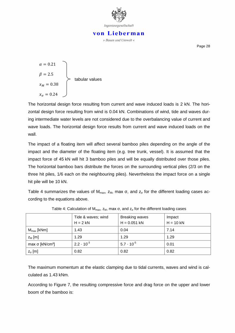
Table 4 summarizes the values of Mmax, zM, max σ, and zσ for the different loading cases ac-
cording to the equations above.
Table 4: Calculation of Mmax, zM, max σ, and zσ for the different loading cases
Tide & waves; wind
H = 2 kN
Breaking waves
H = 0.051 kN
Impact
H = 10 kN
Mmax [kNm] 1.43 0.04 7.14
zM [m] 1.29 1.29 1.29
max σ [kN/cm²] 2.2 · 10-3
5.7 · 10-5
0.01
zσ [m] 0.82 0.82 0.82
The maximum momentum at the elastic clamping due to tidal currents, waves and wind is cal-
culated as 1.43 kNm.
According to Figure 7, the resulting compressive force and drag force on the upper and lower
boom of the bamboo is:
tabular values

Page 29
Figure 7: Distribution of the momentum into a force couple
The bending strength is calculated as:
⁄
Therefore, the proof of the bending strength of single bamboo piles due to current- and wave-
induced loads and wind loads is given.
The maximum horizontal soil pressure due to tidal currents, waves and wind is 2.2 · 10-3
kN/cm². The limit value of the jacket friction can be estimated as 2.5 · 10-3 kN/cm² according to
international standards. Therefore the proof of shear failure is given in this loading case.
The connection of the bamboo piles with horizontal bars distributes the forces and increases
stability. Thus, the proof of the bamboo fence is fulfilled.
Temporary slamming forces caused by breaking waves may increase the momentum on the
bamboo pile for a short period to 0.04 kNm and the maximum horizontal soil pressure to
5.7 · 10-5 kN/cm².
The resulting compressive force and drag force in the upper and lower boom of the bamboo is:
The bending strength is calculated as:
⁄
Therefore, the proof of the bending strength of single bamboo piles due to forces caused by
breaking waves is given.
Page 30
The limit value of the jacket friction can be estimated as 2.5 · 10-3 kN/cm² according to interna-
tional standards. Therefore the proof of shear failure in case of breaking waves is given.
The resulting maximum momentum at the clamping due to an impact is 7.14 kNm and the
maximum horizontal soil pressure 0.01 kN/cm².
The resulting compressive force and drag force in the upper and lower boom of the bamboo is:
Bending strength:
⁄
Therefore, the proof of stability of the construction due to an impact of a floating item of 300 kg
is given.
The maximum possible impact assuming the boundary conditions mentioned above (and fail-
ure of the bamboo piles) is 50.8 kN, which corresponds to the impact of a floating item weigh-
ing 338 kg with a velocity of 0.30 m/s.
The limit value of the jacket friction can be estimated as 2.5 · 10-3 kN/cm² according to interna-
tional standards. Therefore, the proof of shear failure in the case of an impact on the assumed
order of magnitude is not given.
In the case of a larger impact on a single pile, the breakwater will be deformed in the proxi-
mate area of the impact due to the exceeded maximum horizontal soil pressure. If the floating
item hits a larger area of the breakwater, the impact forces will be distributed over more bam-
boo piles and the construction will be stable.
In consideration of risk management, it is not advisable to strengthen the entire construction
due to the relatively low effort to maintain deformed parts of the breakwater in the case of a
significant impact. Reinforcement of the structure would increase costs significantly, while the
risk for damage due to an impact or vandalism is very low.
The calculations above assume an elastic clamping of the bamboo piles into the ground. In the
case of a severe impact, the embedment of affected bamboo piles will be relocated due to
shear failure. It is most likely that the affected piles will not break even in the case of a strong-

Page 31
er impact and can be easily returned to the original position. Even in the case of a major im-
pact on a single pile resulting in the failure of that pile, it can be exchanged quickly and easily.
Estimations concerning geotechnical parameters are especially prone to large uncertainties.
The calculations above are based on conservative assumptions. In natural settings, it is most
likely that the limit value of the jacket friction will be significantly larger. The effective values
can only be determined with on-site tests and measurements. For this reason, the construction
supervision and the tensile tests are of high importance.

Page 32
7 PLANS
7.1 Site maps and description
Detailed planning has been carried out based on the preliminary design. Attachment 1 shows
the site map of the construction including the positions of the breakwater and the fences, the
dimensions and the distances. Attachment 2 shows the site map without the background, and
Attachment 3 shows the locations of the control points. Furthermore, the positions of the sec-
tions are marked on the site map.
In the eastern part of the focus area at Vinh Tan, a bamboo breakwater with a length of 100 m
will be constructed parallel to the shoreline. The heading of the breakwaters’ axis from west to
east is 71.5°. The distance from the revetment at the dyke is 113.08 m, which corresponds
with the distance to the idealized shoreline in the numerical model of 50 m. The basis for the
site map is a GPS survey from 26.01.2011.
In the lee area of the breakwater (relative to the main wave direction) bamboo fences will be
constructed. The heading of the cross-shore fences is 161°; the heading of the longshore
fences is 71°. The cross-shore fences start at the revetment of the dyke and form three main
fields. The connection to the existing flood plain west of the focus area is done with a fourth
smaller field. The area east of the fences lies in the influence of the accretion area of the
breakwater. The four main cross-shore bamboo fences have a length between 50.00 m and
56.70 m. The short fence has a length of 14.20 m. The width of the main fields is 50.00 m; the
width of the smaller field in the west is 40.00 m.
The longshore fences are constructed at the tip of the cross-shore fences. They have a length
of 30.00 m in the main fields; the cross-shore fence is attached in the middle of the longshore
fence. The length of the western longshore fence is 20.00 m. The opening width of the main
fields is 20.00 m; the opening width of the small field is 15.00 m.
On the site map, 13 GPS points are marked, which are used for the placement of the construc-
tion.
7.2 Front views, cross sections and top views
Front views, cross-sections and top views of the bamboo breakwater and the bamboo fences
as well as the connections can be found in Attachments 4 to 12.

Page 33
7.3 Details
Additional details of the constructions can be found in Attachments 13 and 14.
In addition, Figure 8 shows a lashed joint, the most frequently used method of joining bamboo
piles. The tie material is also organic and thus ensures optimal compatibility between the ele-
ments of the structure.
Figure 8: Joint made with rattan strips (DUNKELBERG, 2000)
Page 34
8 CONSTRUCTION PROGRESS
8.1 Preparation and site facilities
Before construction starts, the GPS positions on the crest of the dyke, on the revetment and at
the construction location have to be located and marked. Taking into account the accuracy of
the available data, a horizontal execution accuracy of approximately 1 m is proposed. There-
fore, a standard GPS receiver may be used. To control the positions the headings from one
position to another and the headings of the breakwater and the fences must be controlled by
compass. The dimensions and distances must be controlled by chain or laser measurement.
Due to morphologic changes in the months after the last survey, the elevation of the mud in
the area of the breakwater and the fences has to be determined to calculate the clear height of
the vertical piles above the ground.
No area-consuming site facilities are needed. A place for the storage of the bamboo, the
brushwood, the connection material and the needed tools for the installation has to be installed
behind the dyke, for the construction phase of the bamboo fences. For the construction of the
breakwater, the storage of materials on a pontoon or on a vessel is recommended.
The brushwood has to be roped up into bundles before being brought to the installation loca-
tion.
8.2 Installation
The cross-shore fences near the dyke will mainly be installed manually. The breakwater and
the longshore fences should be installed by means of technical devices from a vessel. There-
fore, different installation methods are necessary.
If the piles are installed manually, a pile hole should be prepared using a sharpened round
timber with a handle bar (cf. Figure 9). The timber is pushed into the mud with a stirring
movement to pre-drill a hole.
Then, if available, the piles can be installed with a pile-driving machine or pressed into the
mud and sand with a dredger bucket (Figure 10). Alternatively a head ram can be used that is
handled by two men. It is also possible to use two men’s weight to press the piles into the soil
with a rope being used to exert force on the pile. If a pile driving machine is used, the head of
the pile has to be protected.

Page 35
Figure 9: Sharpened round timber with a handle bar for the preparation of the installation (left), head ram for the installation of the vertical piles
Figure 10: Installation of vertical piles using a pile-driving machine or a dredger bucket
The best way to install the bamboo piles of the breakwater and the longshore fences is to use
water pressure. Therefore a vessel with electricity, a pump and water is needed. The installa-
tion has to be done during calm weather conditions and when there are adequate water levels
to move the vessel along the breakwater or fence. An immersion pump with a delivery height
of 35 m or more should be used. A hose is attached to the pump; the end section of the hose
is a hollow steel lance. One man holds the pole while another worker controls the lance and
leads it parallel to the bamboo pile. Due to liquefaction of the surrounding soil at the head of

Page 36
the lance, the bamboo pile can be installed into the soil with little pressure. Then the lance can
be pulled out. The lance should be as long as the desired anchoring depth of the pole. The
connection of the hose to the lance can be done using commercial hose connections and a
winding on the lance. A diminution at the head of the lance is advisable to increase pressure at
the head. A movement of the lance (up and down) increases the grade of liquefaction and
makes it easier to plunge the pile.
Figure 11: Steel lance for the installation of the vertical piles with water pressure
If the weather does not allow for the described installation, or if a suitable vessel or equipment
is not available, the piles of the breakwater and the longshore fences can be installed in the
same way as the cross-shore fences near the dyke.
After installation of the vertical bamboo piles, the horizontal bars are attached to the vertical
piles with bamboo strips or jute rope. For both materials, there are different values for tensile
strength. An average value 7 kN/cm² can be assumed. For a rope with a diameter of 1 cm, this
results in a tensile strength of approximately 5.5 kN. The real tensile strength of the connection
material has to be assessed with several on-site tests.
After fitting the brushwood bundles between the bamboo piles and compressing them by man
weight, the piles are connected crosswise with bamboo strips or jute rope. That results in a
mutual reinforcement and avoids leafing of the bundles. The compressing must not be done by
means of machines, e.g. dredger bucket. The smaller branches of the bundles, which are im-

Page 37
portant for the gearing, could be broken. Therefore, the bundles should be handled with care
and by hand as much as possible. Due to their permeability, elastic force and very fine
branches, the bundles dissipate the wave forces very well and reduce the currents significant-
ly. The compression and crosswise connection of the bundles has to be done for each layer of
bundles. Depending on the compressibility of the brushwood, an average 4 layers of bundles
will be installed.
The crest of the breakwater and the longshore fences is at the same elevation as the daily
mean high water level. At the connection to the longshore fences, the cross-shore elements
have the same elevation. Due to the dyke, the elevation of the crest decreases so that a plain
connection to the revetment of the dyke can be realized. This means a gradient of the cross-
shore fences of approximately 1 %. At the dyke, a connection of the cross-shore fences to the
piles of the revetment is done.
The bundles should be approximately 2.00 m long with a diameter of maximum 50 cm. The
branches should be fresh and not brashly. The ends of the trunks should not be thicker than
2.50 cm. The branches should be slender, straight and densely grown.
8.3 Construction sequence
First the construction of the breakwater will be done from west to east. Afterwards the bamboo
fences will be constructed beginning with the westernmost main cross-shore fence (length 50
m) followed by the accordant longshore part. Then the three T-shaped fences to the east will
be constructed in accordance with the described plans. The last structures to be installed will
be the westernmost fences (length of cross-shore fence, 14.20 m).
8.4 Drainage system
An artificial drainage system in the fields accelerates the sedimentation rate. The drainage
system is a network of ditches, which improves the seaward drainage of the areas near the
dyke. Furthermore, the network controls the inflowing water and its sediment load. These sed-
iments are deposited in the ditches. During the maintenance of the ditches, the deposited ma-
terial will be distributed in the fields and increase the elevation there. The ditches are created
either with a dredger or manually.

Page 38
Figure 12 shows the network in the three main fields. Due to its size, the smaller field in the
west of the focus area does not need a drainage system. Figure 13 shows the cross-sections
of the main and the minor ditches.
The installation and maintenance of the drainage system costs money. The creation of a
drainage system depends on the morphologic situation at the time of construction. If the
breakwater and the fences are installed during a period of increased sedimentation, the drain-
age system can be neglected. If the installation is done during a period of increased erosion,
the drainage system should be applied.
Figure 12: Drainage network in a main field
Figure 13: Cross-section of main and minor ditches of the drainage system
Page 39
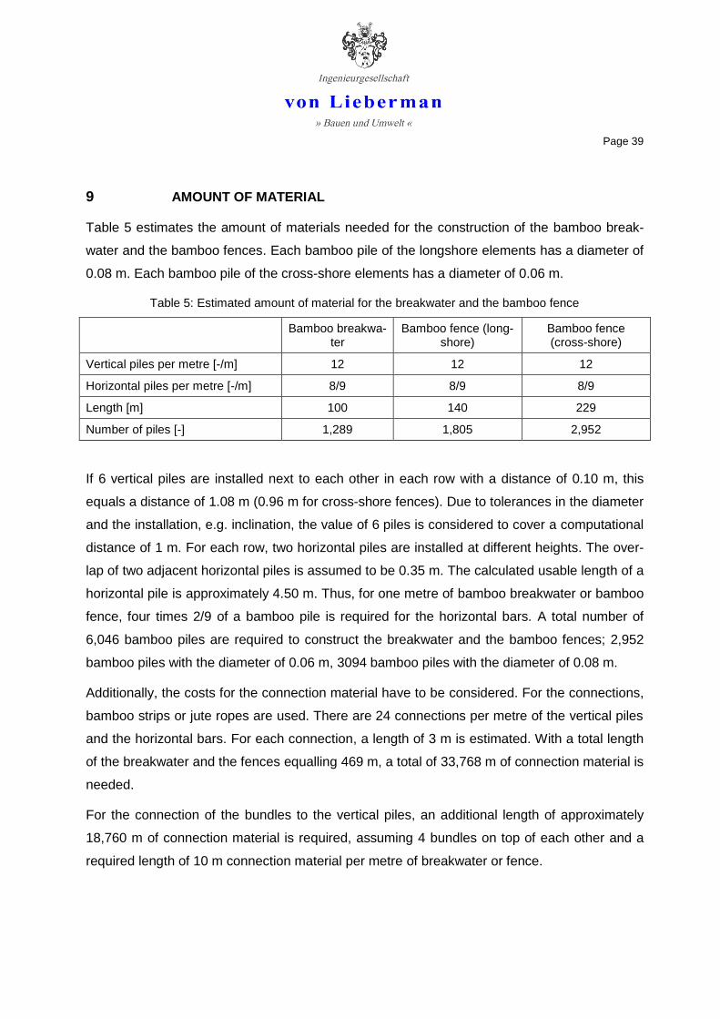
9 AMOUNT OF MATERIAL
Table 5 estimates the amount of materials needed for the construction of the bamboo break-
water and the bamboo fences. Each bamboo pile of the longshore elements has a diameter of
0.08 m. Each bamboo pile of the cross-shore elements has a diameter of 0.06 m.
Table 5: Estimated amount of material for the breakwater and the bamboo fence
Bamboo breakwa-ter
Bamboo fence (long-shore)
Bamboo fence (cross-shore)
Vertical piles per metre [-/m] 12 12 12
Horizontal piles per metre [-/m] 8/9 8/9 8/9
Length [m] 100 140 229
Number of piles [-] 1,289 1,805 2,952
If 6 vertical piles are installed next to each other in each row with a distance of 0.10 m, this
equals a distance of 1.08 m (0.96 m for cross-shore fences). Due to tolerances in the diameter
and the installation, e.g. inclination, the value of 6 piles is considered to cover a computational
distance of 1 m. For each row, two horizontal piles are installed at different heights. The over-
lap of two adjacent horizontal piles is assumed to be 0.35 m. The calculated usable length of a
horizontal pile is approximately 4.50 m. Thus, for one metre of bamboo breakwater or bamboo
fence, four times 2/9 of a bamboo pile is required for the horizontal bars. A total number of
6,046 bamboo piles are required to construct the breakwater and the bamboo fences; 2,952
bamboo piles with the diameter of 0.06 m, 3094 bamboo piles with the diameter of 0.08 m.
Additionally, the costs for the connection material have to be considered. For the connections,
bamboo strips or jute ropes are used. There are 24 connections per metre of the vertical piles
and the horizontal bars. For each connection, a length of 3 m is estimated. With a total length
of the breakwater and the fences equalling 469 m, a total of 33,768 m of connection material is
needed.
For the connection of the bundles to the vertical piles, an additional length of approximately
18,760 m of connection material is required, assuming 4 bundles on top of each other and a
required length of 10 m connection material per metre of breakwater or fence.

Page 40
With the length of a bundle of 2.00 m and an average of 4 bundles on top of each other, ap-
proximately 940 bundles are needed. The brushwood should be bonded at three positions on
each bundle, which results in approximately 15 m rope per bundle. A total length of 14,100 m
rope is also required for the bundles.

Page 41
10 CONSTRUCTION SUPERVISION
A detailed documentation and monitoring of the construction phase is essential to gain infor-
mation for future construction.
The construction supervision must include:
- Visual material control of the bamboo piles, the brushwood and the connection material
including photo documentation
- Random measurements of the length and diameter of the bamboo piles (approximately
every 20th pile) including documentation and analysis
- Random control of the bundles (length, diameter, quality, connections) including docu-
mentation; measurement of approx. every 30th bundle
- Random control of the connection material; approximately 30 breaking tests
- Documentation of the installation method of the vertical piles and additional infor-
mation, e.g. the number of hits
- Documentation of the thickness of the mud layer
- Control and documentation of the depth of embedment
- Control and documentation of the distances between the vertical piles
- Control and documentation of the inclination of the piles
- Visual control of the connections (vertical piles – horizontal bars, vertical piles - bun-
dles) including photo documentation
- Random tensile tests of the vertical bamboo piles; approx. 20 to 30 tests depending on
the soil characteristics
10.1 Tensile tests
Due to uncertainties in the bedding modulus, the maximum horizontal load of the vertical piles
and the breakwater/bamboo fences respectively can only be assessed by means of existing
calculation methods (cf. Chapter 6.2). To get resilient values for the maximum horizontal forc-
es and information about the failure mechanism (soil or bamboo), tensile tests have to be car-
ried out. That will offer valuable information for further installation of bamboo constructions.
Page 42
It is recommended that between 20 and 30 tensile tests be carried out during the installation.
The selection depends on the soil characteristics and the tests should be carried out in differ-
ent locations to get a good sample of the installation.
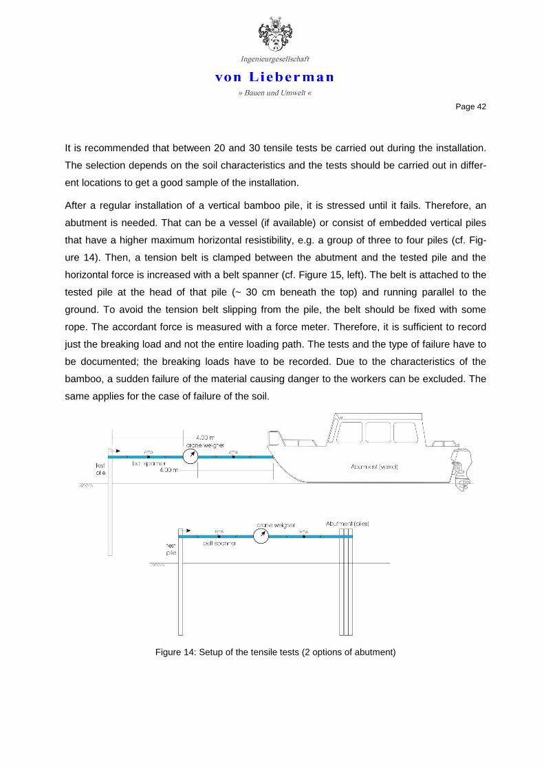
After a regular installation of a vertical bamboo pile, it is stressed until it fails. Therefore, an
abutment is needed. That can be a vessel (if available) or consist of embedded vertical piles
that have a higher maximum horizontal resistibility, e.g. a group of three to four piles (cf. Fig-
ure 14). Then, a tension belt is clamped between the abutment and the tested pile and the
horizontal force is increased with a belt spanner (cf. Figure 15, left). The belt is attached to the
tested pile at the head of that pile (~ 30 cm beneath the top) and running parallel to the
ground. To avoid the tension belt slipping from the pile, the belt should be fixed with some
rope. The accordant force is measured with a force meter. Therefore, it is sufficient to record
just the breaking load and not the entire loading path. The tests and the type of failure have to
be documented; the breaking loads have to be recorded. Due to the characteristics of the
bamboo, a sudden failure of the material causing danger to the workers can be excluded. The
same applies for the case of failure of the soil.
Figure 14: Setup of the tensile tests (2 options of abutment)

Page 43
A standard crane weigher can be used as a force meter (cf. Figure 15, right). The maximum
load should be 600 kg with a resolution of 0.2 kg. The tension belt should have a width of 50
mm, which results in a tensile strength of 40 kN. The length of the tension belt should be 10 m.
Figure 15: Tension belt including belt spanner (left), crane weigher (right)
It is strictly recommended to carry out two or three tensile tests before the construction, to test
and optimize the installation method, to assess the quality of embedment and – if necessary –
to be able to react to changed circumstances, e.g. increased or decrease elevation of the mud
level. Depending on the actual soil characteristics a reduction of the depth of embedment may
be possible.

Page 44
11 OUTLOOK
The construction of the bamboo breakwater and the bamboo fences at Vinh Tan has to be
considered as a pilot project. Detailed documentation and broad monitoring is essential to gain
knowledge for future applications.
In the context of the monitoring program, the development of the shoreline, the floodplains and
the tidal flats between the dyke and the bamboo structures must be recorded. Due to the shal-
low water depths there, soundings by boat are not sufficient. The bottom elevation should be
measured manually using Differential GPS in a 10 m grid. After the first measurement just be-
fore the construction, monthly measurements should initially be carried out; after six months
this interval should be reduced to quarterly measurements.
To assess the effect of the structures compared to other locations where no measures were
applied, one other location must also be monitored regularly parallel to the focus area. This will
help to identify morphodynamic processes that are related to superior trends.
The change of the grain size distribution and the consolidation grade in the area surrounding
of the measurements should be analyzed by means of quarterly sediment sampling in a 25 m
grid.
Measurements of suspended sediment concentrations, waves and currents should be carried
out through campaigns covering different seasons starting immediately after the construction
and continued semi-yearly.
Monthly georeferenced photos should be taken in the focus area. The camera position on the
dyke, the height, the angle and the direction of every photo must be the same to observe the
development of the floodplains.
Aerial views – or better – orthophotos in an annual cycle are helpful to follow and quantify the
morphologic development.
Based on monitoring, the appropriate time for planting mangroves on the tidal flats can be
identified.
All recorded data should be analyzed to provide detailed verification of the success of the
measures.
Page 45
12 REFERENCES
AICHER, S. (2000): Untersuchungen zur Tragfähigkeit der Bambusart ''Guadua Angustfolia''. Otto Graf Institut, Stuttgart
ALBERS, T., LIEBERMAN, N. VON (2011): Management of Natural Resources in the Coastal Zone of Soc Trang Province – Current and Erosion Modelling Survey. Final Report. Published by Deutsche Gesellschaft für Internationale Zusammenarbeit (GIZ) GmbH
ARZ, P., SCHMIDT, H.G., SEITZ, J., SEMPRICH, S. (1991): Grundbau – Sonderdruck aus dem Betonkalender 1991. Grund- und Pfahlbau GmbH, Frankfurt am Main
ATROPS, J. L. (1969): Elastizität und Festigkeit von Bambusrohren. In: Der Bauingenieur 44, Heft 6
DUNKELBERG, K. (2000): Bambus als Baustoff. In: Mitteilungen des Instituts für leichte Flächentragwerke IL Nr. 31, 4. Unveränderte Auflage, Karl Krämer Verlag, Stuttgart
EAK (2002): Empfehlungen des Ausschusses für Küstenschutzwerke – Empfehlungen für Küstenschutzwerke. In: Kuratorium für Forschung im Küsteningenieurwesen (Hrsg.): Die Küste, Heft 65. Heide in Holstein : Boyens, Germany
HALIDE, H., BRINKMANN, R., RIDD, P. (2004): Designing bamboo wave attenuators for mangrove plantations. In: Indian Journal of Marine Science, Vol. 33(3), pp. 220-225
JANSSEN, J. A. (1981): Bamboo in Building Structures. Dissertatie Drukkerij Wibro, Helmond, The Netherlands
JANSSEN, J. A. (1990): Bamboo Research at the Eindhoven University of Technology. Eindhoven, The Netherlands
LINDEMANN, J., STEFFENS, K. (2000): Der Bambus-Pavillion zur EXPO 2000 in Hannover. In: Bautechnik 77, Heft 6+7, Verlag Ernst & Sohn

Page 46
von Lieberman GmbH >> Bauen und Umwelt <<
Dipl.-Ing. Thorsten Albers (Expert River and Coastal Engineering)
DAP-PL-3797.00
Die Akkreditierung gilt für die in der Urkunde aufgeführten Verfahren.

Attachments

N 9°16'44.73''E 105°55'01.45''
100.00
N 9°16'45.79''E 105°55'04.57''
N 9°16'48.24''E 105°55'00.27''
N 9°16'49.28''E 105°55'03.38''
113.08
N 9°16'46.00''E 105°54'53.51''
50.00
N 9°16'46.29''E 105°54'53.41''
N 9°16'44.47''E 105°54'54.06''
N 9°16'48.59''E 105°55'00.15''
N 9°16'49.59''E 105°55'03.25''
Heading 161.5°
Heading 71.5°
11.22
40.00
20.00
30.00
50.00
14.20
20.00
15.00
30.00 m
30.00
30.00
20.00
20.00
50.00
50.00
56.70
53.23
54.30
Site mapBamboo breakwater and fencesCoastal protection Vinh TanDate: 01.07.2011Dipl.-Ing. Thorsten Albers
Heading 161°
Heading 71°
15.0010.00
9.32
Shoreline 26.01.2011 (GPS survey)
Bamboo breakwater/fence

N 9°16'44.73''E 105°55'01.45''
N 9°16'45.79''E 105°55'04.57''
N 9°16'48.24''E 105°55'00.27''
N 9°16'49.28''E 105°55'03.38''
N 9°16'46.00''E 105°54'53.51''
N 9°16'46.29''E 105°54'53.41''
N 9°16'44.47''E 105°54'54.06''
N 9°16'48.59''E 105°55'00.15''
N 9°16'49.59''E 105°55'03.25''
Heading 161.5°
Heading 71.5°
Control pointsBamboo breakwater and fencesCoastal protection Vinh TanDate: 01.07.2011Dipl.-Ing. Thorsten Albers
Heading 161°Heading 71°
Bamboo breakwater/fence
100 m
N 9°16'46.68''E 105°54'54.96''
N 9°16'47.41''E 105°54'56.51''
N 9°16'47.90''E 105°54'58.06''
Heading 161°
N 9°16'44.38''E 105°54'52.67''

N 9°16'44.73''E 105°55'01.45''
100.00
N 9°16'45.79''E 105°55'04.57''
N 9°16'48.24''E 105°55'00.27''
N 9°16'49.28''E 105°55'03.38''
113.08
N 9°16'46.00''E 105°54'53.51''
50.00
N 9°16'46.29''E 105°54'53.41''
N 9°16'44.47''E 105°54'54.06''
N 9°16'48.59''E 105°55'00.15''
N 9°16'49.59''E 105°55'03.25''
Heading 161.5°
Heading 71.5°
11.22
40.00
20.00
30.00
50.00
14.20
20.00
15.00
30.00 m
30.00
30.00
20.00
20.00
50.00
50.00
56.70
53.23
54.30
Site map (without background)Bamboo breakwater and fencesCoastal protection Vinh TanDate: 01.07.2011Dipl.-Ing. Thorsten Albers
Heading 161°
Heading 71°
15.0010.00
9.32
Shoreline 26.01.2011 (GPS survey)
Bamboo breakwater/fence
100 m
A
AB
B
A
A
B
B
F
F
E
E
J
I
K
K

2.6
0
0.1
6
0.08
4.7
0
2.1
0
Mud
Sand
1.3
00.8
0
0.10
0.6
21.1
4
0.0
8
1.08
A
A
Vietnamese National Datum
1.10 Detail 2
-0.20
von Lieberman GmbH does not assume liability for mistakes in this plan.
Name Date Client:
Drawn: T. Albers 01.08.2011 GIZ Soc Trang
Checked:
Project no.:
13713-01
Scale:
1:20
Attachment:
5
Content:
von Lieberman GmbH
Ruhrstr. 57, 22761 Hamburg
Tel.: 040 / 500 99 3 -0
Fax.: 040 / 500 99 3 -33File: bambus_110330.dwg
Bamboo breakwater /
longshore fence
Section B-B

2.6
0
MHHW
MLHW
0.50
0.1
6
0.08
Detail 1
B
Mud
Sand
B
1.3
0
Width 0.50
Height 0.30 - 0.35
Length 2.000.8
0
0.3
0
2.1
0
4.7
0
0.3
5
0.6
2
1.1
4
3.4
0
0.6
8
0.0
8
C C
-0.20
1.10
D D
von Lieberman GmbH does not assume liability for mistakes in this plan.
Name Date Client:
Drawn: T. Albers 01.08.2011 GIZ Soc Trang
Checked:
Project no.:
13713-01
Scale:
1:20
Attachment:
4
Content:
von Lieberman GmbH
Ruhrstr. 57, 22761 Hamburg
Tel.: 040 / 500 99 3 -0
Fax.: 040 / 500 99 3 -33File: bambus_110330.dwg
Bamboo breakwater /
longshore fence
Section A-A

2.6
0
MHHW
MLHW
0.40
0.1
2
0.06
Detail 3
Mud
Sand
1.3
0
Width 0.40
Height 0.25 - 0.35
Length 2.00
0.8
0
0.2
8
2.1
0
4.7
0
0.3
3
0.6
21.1
3
3.4
0
0.6
8
0.0
6
G G
-0.20
1.10
H H
F
F
von Lieberman GmbH does not assume liability for mistakes in this plan.
Name Date Client:
Drawn: T. Albers 01.08.2011 GIZ Soc Trang
Checked:
Project no.:
13713-01
Scale:
1:20
Attachment:
7
Content:
von Lieberman GmbH
Ruhrstr. 57, 22761 Hamburg
Tel.: 040 / 500 99 3 -0
Fax.: 040 / 500 99 3 -33File: bambus_110330.dwg
Bamboo fence
cross-shore
Section E-E

0.50
0.08
0.3
5
0.3
50
.08
0.1
0
Ove
rla
pp
ing
of
the
ho
rizo
nta
l b
ars
Pe
rpe
nt
join
t o
f th
e
fag
go
ts s
tag
ge
red
in la
ye
rs,
D >
0.5
0
0.5
6
Sta
gg
ere
d o
f th
e
ove
rla
pp
ing
of
the
ho
rizo
nta
l b
ars
D >
0.5
0
0.50
0.0
8
0.1
0
Pe
rpe
nt
join
t o
f th
e
fag
go
ts s
tag
ge
red
in la
ye
rs,
D >
0.5
0
von Lieberman GmbH does not assume liability for mistakes in this plan.
Name Date Client:
Drawn: T. Albers 02.08.2011 GIZ Soc Trang
Checked:
Project no.:
13713-01
Scale:
1:12.5
Attachment:
6
Content:
von Lieberman GmbH
Ruhrstr. 57, 22761 Hamburg
Tel.: 040 / 500 99 3 -0
Fax.: 040 / 500 99 3 -33File: bambus_110330.dwg
Bamboo breakwater /
longshore fence
Section C-C and D-D
Section C-C Section D-D

2.6
0
0.1
2
0.06
4.7
0
2.1
0
Mud
Sand
1.3
00.8
0
0.10
0.6
21.1
3
0.0
6
0.96
Vietnamese National Datum
1.10Detail 4
0.0
6
-0.20
E
E
von Lieberman GmbH does not assume liability for mistakes in this plan.
Name Date Client:
Drawn: T. Albers 01.08.2011 GIZ Soc Trang
Checked:
Project no.:
13713-01
Scale:
1:20
Attachment:
8
Content:
von Lieberman GmbH
Ruhrstr. 57, 22761 Hamburg
Tel.: 040 / 500 99 3 -0
Fax.: 040 / 500 99 3 -33File: bambus_110330.dwg
Bamboo fence
cross-shore
Section F-F

0.40
0.06
0.3
5
0.3
50
.06
0.1
0
Ove
rla
pp
ing
of
the
ho
rizo
nta
l b
ars
Pe
rpe
nt
join
t o
f th
e
fag
go
ts s
tag
ge
red
in la
ye
rs D
> 0
.50
0.5
6
Sta
gg
ere
d o
f th
e
ove
rla
pp
ing
of
the
ho
rizo
nta
l b
ars
D >
0.5
0
0.40
0.0
6
0.1
0
Pe
rpe
nt
join
t o
f th
e
fag
go
ts s
tag
ge
red
in la
ye
rs D
> 0
.50
von Lieberman GmbH does not assume liability for mistakes in this plan.
Name Date Client:
Drawn: T. Albers 02.08.2011 GIZ Soc Trang
Checked:
Project no.:
13713-01
Scale:
1:12.5
Attachment:
9
Content:
von Lieberman GmbH
Ruhrstr. 57, 22761 Hamburg
Tel.: 040 / 500 99 3 -0
Fax.: 040 / 500 99 3 -33File: bambus_110330.dwg
Bamboo fence
cross-shore
Section G-G and H-H
Section G-G Section H-H

0.50
0.08
0.0
8
Perpent joint of the
faggots staggered
in layers, D > 0.500.4
0
0.06
0.10
0.0
6
0.1
0
2.000
.28
von Lieberman GmbH does not assume liability for mistakes in this plan.
Name Date Client:
Drawn: T. Albers 23.08.2011 GIZ Soc Trang
Checked:
Project no.:
13713-01
Scale:
1:12.5
Attachment:
10
Content:
von Lieberman GmbH
Ruhrstr. 57, 22761 Hamburg
Tel.: 040 / 500 99 3 -0
Fax.: 040 / 500 99 3 -33File: bambus_110330.dwg
Bamboo longshore /
cross-shore fence
Connection
Section I

0.4
0
0.06
0.10
0.0
6
2.00
0.2
8
0.3
6
Distance of existing
piles variable
Set new pile if
necessary,
diameter 0.08
Revetment
von Lieberman GmbH does not assume liability for mistakes in this plan.
Name Date Client:
Drawn: T. Albers 23.08.2011 GIZ Soc Trang
Checked:
Project no.:
13713-01
Scale:
1:10
Attachment:
11
Content:
von Lieberman GmbH
Ruhrstr. 57, 22761 Hamburg
Tel.: 040 / 500 99 3 -0
Fax.: 040 / 500 99 3 -33File: bambus_110330.dwg
Bamboo cross-shore fence
Connection to revetment
Section J

53.23
1.100.50 1.13 %
3.2
0
54.30
1.100.50 1.11 %
-0.20
4.7
0
3.2
0
56.70
1.100.50 1.06 %
-0.20
4.7
0
3.2
0
-0.20
4.7
0
50.00
1.100.50 1.20 %
3.2
0
-0.20
4.7
0
14.20
1.101.10
4.7
0
-0.20
4.7
0
von Lieberman GmbH does not assume liability for mistakes in this plan.
Name Date Client:
Drawn: T. Albers 02.08.2011 GIZ Soc Trang
Checked:
Project no.:
13713-01
Scale:
1:200
Attachment:
12
Content:
von Lieberman GmbH
Ruhrstr. 57, 22761 Hamburg
Tel.: 040 / 500 99 3 -0
Fax.: 040 / 500 99 3 -33File: bambus_110330.dwg
Bamboo fences
Side view
Section K-K

0.08 0.50 0.08
0.0
8
0.3
0
Bundles:
Width 0.50
Compressed height 0.30 - 0.35
Length 2.00
Lashed joint
0.0
1
Horizontal bar
Vertical pile
0.3
5
0.08
0.0
8
0.10
Horizontal bar
Lashed joint
Vertical pile
Crosswise
bracing of the
bundles
von Lieberman GmbH does not assume liability for mistakes in this plan.
Name Date Client:
Drawn: T. Albers 15.10.2011 GIZ Soc Trang
Checked:
Project no.:
13713-01
Scale:
1:5
Attachment:
13
Content:
von Lieberman GmbH
Ruhrstr. 57, 22761 Hamburg
Tel.: 040 / 500 99 3 -0
Fax.: 040 / 500 99 3 -33File: bambus_110330.dwg
Bamboo breakwater /
longshore fence
Details 1 and 2
Detail 1 Detail 2

Bundles:
Width 0.40
Height 0.25 - 0.35
Length 2.00
0.06 0.40 0.06
0.0
6 0.0
1
Lashed joint
Horizontal bar
Vertical pile
0.3
1
0.3
5
0.06
0.0
6
0.10
Horizontal bar
Lashed joint
Vertical pile
Crosswise
bracing of the
bundles
von Lieberman GmbH does not assume liability for mistakes in this plan.
Name Date Client:
Drawn: T. Albers 15.10.2011 GIZ Soc Trang
Checked:
Project no.:
13713-01
Scale:
1:5
Attachment:
14
Content:
von Lieberman GmbH
Ruhrstr. 57, 22761 Hamburg
Tel.: 040 / 500 99 3 -0
Fax.: 040 / 500 99 3 -33File: bambus_110330.dwg
Bamboo fence
cross-shore
Details 3 and 4
Detail 3 Detail 4


![Stability of Low Crested and Submerged Breakwaters with ...€¦ · breakwaters has been extensively studied [15], and the stability on low crested and submerged breakwaters was addressed](https://static.fdocuments.in/doc/165x107/5fc2e4ed58734d00807b1cc4/stability-of-low-crested-and-submerged-breakwaters-with-breakwaters-has-been.jpg)


