Czesław Rybicki Well TeSTIng In Shale gaS ReSeRVoIR – neW...
13
Czesław Rybicki* Well TeSTIng In Shale gaS ReSeRVoIR – neW IDea** 1. InTRoDuCTIon Countries around the world are focusing efforts on developing more natural gas resour- ces to improve their economies. Today, unconventional gas resources are targets for develop- ment in order to contribute to a national energy mix. Better recognition of the unconventional gas reservoirs allow us to obtain good results after discovering them. Generally all hydrocar- bons reservoirs can be divided into two types: – conventional reservoirs, – unconventional reservoirs. Conventional reservoirs belong these reservoirs which can be used directly after the dis- covering process. Unconventional reservoirs – reservoirs which after the discovery process have to be prepared to be effective. The main subject of this paper is giving some details about the testing methods of unconventional reservoirs and their properties and characteristics. 2. ChaRaCTeRISTICS of unConVenTIonal ReSeRVoIRS The unconventional reservoirs including: tight gas reservoirs, coalbed methane and shale gas reservoirs have specific properties. There are: – low permeability, – very poor inner transport systems, – reservoir fluid (gas) is in two or three states – as a free gas in pores, free gas in naturally fractures, adsorbed gas and/or probably as a condensated phase. The reality for unconventional gas reservoirs including low-permeability ones is that flu- id storage and transport mechanisms are poorly understood, and often special in Poland we are at an early stage for some reservoir types in the development of such methods. Further, it is not just necessary to characterize the reservoir in unconventional plays but also the induced hydraulic fracture(s) or fracture network, that have a large influence on well performance, and further production process. http://dx.doi.org/10.7494/drill.2014.31.3.441 * AGH University of Science and Technology, Faculty of Drilling, Oil and Gas, Krakow, Poland ** Paper prepared within statutory research program AGH DRILLING, OIL, GAS • Vol. 31 • No. 3 • 2014 441
Transcript of Czesław Rybicki Well TeSTIng In Shale gaS ReSeRVoIR – neW...

Czesław Rybicki*
Well TeSTIng In Shale gaS ReSeRVoIR – neW IDea**
1. InTRoDuCTIon
Countries around the world are focusing efforts on developing more natural gas resour-ces to improve their economies. Today, unconventional gas resources are targets for develop-ment in order to contribute to a national energy mix. Better recognition of the unconventional gas reservoirs allow us to obtain good results after discovering them. Generally all hydrocar-bons reservoirs can be divided into two types:
– conventional reservoirs,– unconventional reservoirs.
Conventional reservoirs belong these reservoirs which can be used directly after the dis-covering process. Unconventional reservoirs – reservoirs which after the discovery process have to be prepared to be effective. The main subject of this paper is giving some details about the testing methods of unconventional reservoirs and their properties and characteristics.
2. ChaRaCTeRISTICS of unConVenTIonal ReSeRVoIRS
The unconventional reservoirs including: tight gas reservoirs, coalbed methane and shale gas reservoirs have specific properties. There are:
– low permeability,– very poor inner transport systems,– reservoir fluid (gas) is in two or three states – as a free gas in pores, free gas in naturally
fractures, adsorbed gas and/or probably as a condensated phase.
The reality for unconventional gas reservoirs including low-permeability ones is that flu-id storage and transport mechanisms are poorly understood, and often special in Poland we are at an early stage for some reservoir types in the development of such methods. Further, it is not just necessary to characterize the reservoir in unconventional plays but also the induced hydraulic fracture(s) or fracture network, that have a large influence on well performance, and further production process.
http://dx.doi.org/10.7494/drill.2014.31.3.441
* AGH University of Science and Technology, Faculty of Drilling, Oil and Gas, Krakow, Poland** Paper prepared within statutory research program
AGH DRILLING, OIL, GAS • Vol. 31 • No. 3 • 2014
441
442
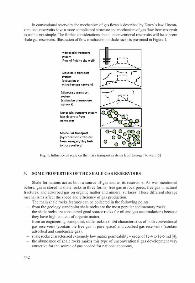
In conventional reservoirs the mechanism of gas flows is described by Darcy’s law. Uncon-ventional reservoirs have a more complicated structure and mechanism of gas flow from reservoir to well is not simple. The further considerations about unconventional reservoirs will be concern shale gas reservoirs. Illustration of flow mechanism in shale rocks is presented in Figure 1.
fig. 1. Influence of scale on the mass transport systems from kerogen to well [5]
3. SoMe pRopeRTIeS of The Shale gaS ReSeRVoIRS
Shale formations act as both a source of gas and as its reservoirs. As was mentioned before, gas is stored in shale rocks in three forms: free gas in rock pores, free gas in natural fractures, and adsorbed gas on organic matter and mineral surfaces. These different storage mechanisms affect the speed and efficiency of gas production.
The main shale rocks features can be collected in the following points:– from the geology standpoint shale rocks are the most popular sedimentary rocks,– the shale rocks are considered good source rocks for oil and gas accumulations because
they have high content of organic matter,– from an engineering standpoint, shale rocks exhibit characteristics of both conventional
gas reservoirs (contain the free gas in pore space) and coalbed gas reservoirs (contain adsorbed and condensate gas),
– shale rocks characterized extremely low matrix permeability – order of 1e-4 to 1e-5 md [4],– the abundance of shale rocks makes this type of unconventional gas development very
attractive for the source of gas needed for national economy,

443
– shale rocks may be characterized by their organic content,– the organic matter in shale rocks results from geological digenesis process in which
mainly plant and animal material is deposited with other sediments,– the organic matter is composed of two components: bitumen (characterized by smaller
molecules, soluble in organic solvents) and kerogen (characterized by larger molecules, insoluble in organic solvents),
– under high pressure and high temperature conditions, hydrocarbon fluids can be re-leased from organic matter and stored within the porosity of the shale or they can mi-grate to other formations,
– the maturity of the organic matter is defined by the maximum temperature level reached during the catagenesis processes, thus transforming the matter into hydrocarbon fluids (cracking processes),
– the remaining organic matter usually has an affinity for hydrocarbon molecules, so some hydrocarbons (in particular gases) can be adsorbed at their surfaces in shale matrix,
– in very narrow pore fracture space there are acting very high capillary forces, which cause, that the hydrocarbons can be in a liquid phase (capillary condensation),
– beside of hydrocarbons non-hydrocarbon gases as carbon dioxide or nitrogen are also known to adsorb in shales.
Structure of shale rocks in comparison to conventional one is presented in Figure 2.
fig. 2. Comparison of conventional and unconventional gas reservoirs: a) conventional gas reservoir; b) unconventional gas reservoir [8]
In order to activate the unconventional reservoirs to start the production of gas one should make hydraulic fracturing horizontal wells. The main goal of hydraulic fracturing is connecting possible great quantities of micropores shown in Figure 2 and create the transport system to flow of gas towards wells. The hydraulic fracturing of shale rocks is not a simple process because they have very big compressibility in comparison to conventional rocks. Rock compressibility coef-ficient of conventional rocks is about cp = 4 – 6 ∙ 10−10 1/Pa and rock compressibility coefficient
a) b)

444
of shale rocks is about cp = 2 – 4 ∙ 10−8 1/Pa [7]. The great difference causes that during the hy-draulic fracturing of shale one should appropriate propant selected. If the propant will be not good fitted, after hydraulic fracturing created fractures will crash. Analysing of shale rocks behaviour as reservoir of the natural gas, it is possible to treat them as heterogeneous media about the double porosity. The next part of this paper will explain the types of rock heterogeneousness.
4. RoCK heTeRogeneouSneSS
Generally in reservoir engineering all rocks creating reservoirs in respect of their homo-geneity are divided into two groups:
– homogeneous,– heterogeneous.
Practically homogeneous rocks are only in assumptions which are taken for simplifica-tions of calculations. From a practical point of view mostly rocks are heterogeneous:
In reservoir engineering there are mainly three types heterogeneousness:– double porosity,– double permeability,– composite.
As it is known that in double porosity reservoirs there are two systems with different po-rosity and one of them has very big permeability and it has contact with the well. In the case of double permeability reservoirs there are two systems with different porosity and permea-bility but both have contact with wells. In composite reservoirs there are a few zones which differ the porosity and permeability located theoretically concentrically around the well. Generally in reservoir engineering of shale rocks is taken that structure of them dual porosity model gives goo description. As is known the shale rocks have very low permeability, then to activate the flow of fluid it should be carried out hydraulic fracturing. This process leads to creation of fracture systems which can be simple or more advance.
Two conceptual dual porosity models are presented in Figure 3 [1].
fig. 3. Models of double porosity structure: a) simple systems of fractures dividing the massive on the long blocks; b) advanced systems of fractures [1]
a) b)HydraulicFracture
Spacing, L1
Drainage area length, Xc
horizontal Well horizontal Well
Drainage area length, Xc
Frac
ture
Hal
f len
gth,
Yc
HydraulicFractures Natural Fracture
NetworkUnknown
L2
MatrixMatrix

445
5. Well TeSTIng
For recognise rock properties as gas reservoirs it is necessary to carried out well tests. In reservoir engineering there is many well tests.
Among the well test which used to give information about the reservoir properties are the following [9, 10, 3]:
– buildup tests,– drawdown tests,– injection/falloff tests.
Buildup tests relay on the well head closing and observation of character pressure increas-ing during the time. Drawdown tests relay on observation pressure change during the normal production process. Injection/Falloff tests relay on injection some fluid (for example Nitrogen) to the pore – fracture systems and after end of this, observation pressure decreasing. Most pop-ular method interpretation of well test results is “log – log diagnostic method”. In this method diagnostic and specialize graphs are constructed. Log – log diagnostic method relay on the con-struction two graphs. One of them is plot of change pressure during the build up time for build up test or difference pressure change during the drawdown test or injection/falloff tests. Second graph that is a plot of logarithmic derivative of pressure or pressure difference p′ as a function on time t. Derivative is calculated numerically according to the following relationship.
′ = =p dpd t
t dpdt(ln )
(1)
Example of such graphs for horizontal well is presented on Figure 4.
fig. 4. Diagnostic graph presenting the comprehensive reservoir characterization of tested layers in horizontal wells [11]
Mathematical description of both tests is supported on the following relationships de-rived by van Everdingen and Hust [6] as a constant rate solution of mathematical model of fluid filtration process.

446
pD = 0,5 (lntD + 0.809) (2)
where:
(3)
The full equation for describing gas flow from reservoir to well or inversely has follow-ing form [6, 1]:
(4)
At equation (3) cg is gas compressibility coefficient. It is assumed that gas is in free stage as only one phase in the reservoirs. This is true for conventional reservoir. Regarding the be-havior of shale gas reservoirs as dual porosity system it assumed that the gas is in free states inside the matrix blocks and main gas transport is by fractures. As it was mentioned above gas in shales is not only in free state. In the author’s opinion the gas in shale is in adsorbed stage and in a condensed state. The author have tried to introduce new concept describing of test by taking into account the gas sorption and desorption process in mathematical de-scription of shale gas production process compressibility of rock and water. In a further part of paper there will be presented details.
6. SoMe eleMenTS of gaS fIlTRaTIon TheoRy In RoCKS
The mathematical model of the fluid flow in porous media constitute the following equations:
– the mass conservation equation,– the filtration equation,– the state equation,– the energy conservation equation.
The mass conservation equationThe continuity equation expresses comparison of substantional and local changes dur-
ing the fluid flow in porous media. This equation can written in following form:
(5)
The equation (1) may be express in the differential form:
(6)

447
It is possible to save this equation in the shorter form:
(7)
The left hand of this equation is substantional changes (difference between outflow and inflow), left side are local changes (resulting from the change of the fluid density).
Classification of reservoir fluidsReservoir fluids on account of their compressibility it is possible to divide on:
– incompressible,– compressible.
Compressible fluids are divided into low compressible (liquids) and high compressible (gases).
The compressibility coefficient of fluid is expressed by the relation:
(8)
It is possible to write this equation with the fluid density as:
(9)
For the low compressible fluid c << 1 and const. For the gas as a high compressible fluid compressibility coefficient may be expressed by following relation:
(10)
For ideal gas it is possible to write:
cpg =1 (11)
The filtration equationThe base filtration equation used in reservoir engineering is Darcy’s law. Darcy intro-
duce the idea of filtration velocity defined by:
w qA
def
= (12)
For the laminar flows Darcy has derived following equation:
(13)

448
From this relation it results that the filtration velocity is proportional to a gradient of the pressure, and proportionality constant is the rate of rock permeability and fluid visco-sity. As was mentioned above equation (13) is valid only for laminar flows. Character of flow depends on Reynolds number Re. In reservoir engineering it is taken:
– for Re < 1 – range of laminar flow,– for 1 < Re < 10 – transient range,– for Re > 10 – range of turbulence flow.
In real cases of fluid flow in porous media flows of fluids are sometimes laminar and some-times turbulence.
In engineering the is equation which is a development of the Darcy equation. That is a For-chheimer equation written in following form:
(14)
equation of stateFor the low compressible fluid (liquid) equation of state may be written in the following
form:
(15)
Or in converted form:
(16)
For the high compressible fluid (gas) equation of state may be written in the following form:
(17)
energy conservation equation
During the production process of hydrocarbon reservoirs it is an observed phenomenon that reservoir temperature is almost constant. This observation gives us to assume that the pro-duction process is isothermal one. From thermodynamics it is known that for the isothermal process changes of energy are equal zero. And so it is possible to omit taking into account the energy conservation equation Based on three equations of the continuity, the filtration and the state, after transforming them it can derived differential equation being a mathemat-ical description of the flow of low compressible fluids in porous media. This equation has a form:
(18)

449
For the gas equation (14) takes form:
(19)
Equation (19) is valid for gas reservoir where there is only gas and there is volumetric reservoir.
7. IMpaCT of Shale gaS ReSeRVoIR pRopeRTy on MaTheMaTICal DeSCRIpTIon of gaS fIlTRaTIon pRoCeSS
In case of shale gas reservoir it is necessary to take the following conditions:– in shale there is free gas in macropores,– shale rock is compressible one,– in rock there is water which is also compressible,– during the gas production process of gas from shale it will the gas desorption pro-
cess from micropores.
Taken these conditions one can equation (19) write in following form:
(20)
In reservoir engineering to describe volume of gas adsorption and desorption is used Langmuir’s isotherm expressed by following equation:
VV pp pad
L g
L g
=+
(21)
One may assume that shale compressibility coefficient cm and water compressibility co-
efficient cw are constant. Gas density one may calculate from equation (17).With regards to equations (17) and (21) with the assumption that permeability k and po-
rosity f are constant equation (20) takes the following form:
(22)
Expression in the brackets on the right hand one may to name as a complex compressi-bility coefficient for reservoir fluids. The value of this coefficient depends on the pressure pg. This pressure during the production process is changeable. To simplify this problem it is pos-sible to take the value of this coefficient according to some value of pressure. This pressure is defined as average pressure.

450
McKee, Bumb and Koenig [7] have proposed to calculate average pressure for com-pressible rocks from following relation:
pav = 0,9pi + 0,1pg (23)
Taken the value of average pressure one may write the following equation for the calcu-lation of the complex compressibility coefficient of shale reservoir fluid:
(24)
With taking into account equation (24), equation (22) it can write in following form:
(25)
To solve equation (25) one may use Boltzmann transformation [6] defined by following relationship:
(26)
Because the gas on the way between reservoir and well changes its viscosity μg and com-pressibility coefficient zg is purposeful the use the pseudo pressure function m(p) [2] instead of pressure in following form:
(27)
Finishing solution of equation (25) with using equation (27) will have following form:
(28)
where:
(29)
When the value of dimensionless time tD defined by equation (3) greater than 100 (in practice this condition is accomplished very quickly after the start of the production) equa-tion (28) can be written in the following form:
(30)

451
where:
The author proposes equation (30) to use to interpretation of well tests carried out in shale rocks.
8. ConClUsIons
Analysing the problem of the description of results of hydrodynamic tests carried out on shale gas it is possible to formulate following conclusions:
1. At present it grows interest of unconventional gas reservoirs specially shale gas.2. Shales have very low permeability, very poor inner transport systems and reservoir
fluid (gas) is in two or three stages – as a free gas in pores, free gas in naturally frac-tures, adsorbed gas and/or probably as a condensate phase.
3. Shale have big compressibility in comparison to conventional rocks.4. During the results interpretation of well tests can use traditional methods but it need
to introduce some corrections due to compressibility and the gas sorption and deso-rption process.
5. It needs to carry out laboratory research to find answers to questions: Is only gas (meth-ane) adsorbed in shales?, Is it in liquid form?, Is some similarity shale gas to coalbed methane?
noMenClAtURe
A – surface of rock [m2],
c – isothermal compressibility coefficient [1/Pa],
cg – gas compressibility coefficient [1/Pa],
cm – rock compressibility coefficient [1/Pa],
cw – water compressibility coefficient [1/Pa],
h – thickness [m],
k – permeability [m2],
m(p) – pseudo pressure function [Pa/s],
p – pressure [Pa],
pi – initial pressure [Pa],
p′ – pressure derivative [Pa],
pL – Langmuir pressure [Pa],
pg – gas pressure [Pa],
po – some chosen value of pressure [Pa],

452
pn – standard pressure = 101,325 Pa,
pD – dimensionless pressure function [–],
R – individual gas constant [J/kg K],
r – radius [m],
s – Boltzmann transformation [–],
Sw – water saturation [–],
T – temperature [K],
Tn – standard temperature = 273.15 K,
t – time [s],
tD – dimensionless time defined by eg. (3),
Vad – adsorbed gas volume [m3]
VL – Langmuir volume [m3],
w – filtration velocity [m/s],
x, y, z – coordinates [m],
zg – gas compressibility factor [–],
α – specific rock parameter defined by McKee, Bumb, Koenig [7],
β – rock turbulence coefficient [1/m],
ϕ – rock porosity [–],
μg – gas viscosity [Pas],
ρ – density [kg/m3],
ρg – gas density [kg/m3],
ρgn – gas density at standard conditions [kg/m3].
RefeRenCes
[1] Al-Ahmadi H.A., Almarzooq A.M., Wattenbarger R.A.: Application of Linear Flow Analysis to Shale Gas Well – Field Cases. SPE 130370, 2010.
[2] Al-Hussainy R., Ramey R., Crawford H.J.: The Flow of Real Gases Through Porous Media. JPT, SPE 1243A, 1966.
[3] Ambrose Ray J., Clarkson C.R.: Youngblood Jerry, Life-Cycle Decline Curve Estima-tion for Tight/Shale Gas Reservoirs. SPE 140519, 2011.
[4] Cipolla C.L., Lolon E.P.: Modelling Well Performance in Shale-Gas Reservoirs. SPE 125532, 2009.

[5] Clarkson C.R., Jensen J.L., Blasingame T.A.: Reservoir Engineering for Unconvention-al; Gas Reservoirs: What do We Have to Consider?. SPE 145080, 2011.
[6] Dake L.P.: Fundamentals of reservoir Engineering. Elsevier S.P. 1978. [7] McKee C.R., Bumb A.C., Koenig R.A., Stress Dependent Permeability and porosity
of Coal and Other Geologic Formations. SPE Formation Evaluation, March 1988. [8] Poprawa P.: Potencjał dla poszukiwań złóż gazu ziemnego w łupkach dolnego paleo-
zoiku (shale gas) w Polsce. Materiały z konferencji: „Niekonwencjonalne złoża gazu ziemnego w Polsce – gaz w łupkach (shale gas) i gaz zamknięty (tight gas)”. Warszawa, 27.01.2010.
[9] Rybicki C.: Hydrodynamiczne i gazodynamiczne metody badania, otworów i złóż węglowodorów. Technika Naftowa i Gazownicza, part 3, 1989.
[10] Umberto J., Borges A.: Well Test Analysis in Tight Gas reservoirs. SPE 121113, 2009. [11] Well Test Interpretation. Schlumberger 2002.