
Cylinder Lubrication Update (SL2013-571-JAP)
17
Service Letter SL2013-571/JAP Action code: WHEN CONVENIENT Head office (& postal address) MAN Diesel & Turbo Teglholmsgade 41 2450 Copenhagen SV Denmark Phone: +45 33 85 11 00 Fax: +45 33 85 10 30 [email protected] www.mandieselturbo.com PrimeServ Teglholmsgade 41 2450 Copenhagen SV Denmark Phone: +45 33 85 11 00 Fax: +45 33 85 10 49 [email protected] Production Teglholmsgade 35 2450 Copenhagen SV Denmark Phone: +45 33 85 11 00 Fax: +45 33 85 10 17 [email protected] Forwarding & Receiving Teglholmsgade 35 2450 Copenhagen SV Denmark Phone: +45 33 85 11 00 Fax: +45 33 85 10 16 [email protected] MAN Diesel & Turbo Branch of MAN Diesel & Turbo SE, Germany CVR No.: 31611792 Head office: Teglholmsgade 41 2450 Copenhagen SV, Denmark German Reg.No.: HRB 22056 Amtsgericht Augsburg Cylinder Lubrication Update Adjusting the ACC factor in service Replaces SL07-479 and SL09-507 SL2013-571/JAP May 2013 Concerns All ME/ME-C/ME-B/ME/MC/MC-C and ME-GI engines with electronically con- trolled lubricators. Summary New cylinder oil lubrication recommen- dation. Guiding ACC values for all engines: ACC range 0.20-0.34 g/kWh x S%, minimum 0.60 g/kWh. Dear Sirs Our guidelines on cylinder lubrication of MAN B&W low speed engines have called for an update in response to the below development: ■ recent changes in operational patterns towards lower-load operation ■ development of new cylinder oils aiming at being better able to cater for a larger variation of fuel oil sulphur contents ■ the general development of engines towards larger stroke-to-bore ratios and changed process parameters triggered by environmental compliance rules. In conclusion of the above, MAN Diesel & Turbo recommends the following: ■ lubrication with cylinder oils with at least the same acid neutralisa- tion ability as the traditional BN 70 cylinder lube oils, i.e. BN 70-100 and SAE 50, on our newest engine designs (Mk 9 type and newer engines) when operating on high sulphur heavy fuel oil. ■ increased lube oil feed rate or lubrication with higher-BN oils on part- load and low-load fuel-optimised engines requiring increased neu- tralisation ability. ■ Lubricator part load control break point set at 50% for Mk 8 and newer. This service letter replaces the previous service letters SL2007-479 and SL2009-507. Guidelines for mechanical lubrication are found in SL2000-385 and SL2012-553. Yours faithfully Stig B Jakobsen Senior Manager Operation Mikael C Jensen Vice President Engineering Scavenge Drain Oil Fe mg/kg 50-150 BN mg KOH/kg 200-300 > 300 > 25 15 < 10
Transcript of Cylinder Lubrication Update (SL2013-571-JAP)

Service Letter SL2013-571/JAP
Action code: WHEN CONVENIENT
Head office (& postal address)MAN Diesel & TurboTeglholmsgade 412450 Copenhagen SVDenmarkPhone: +45 33 85 11 00Fax: +45 33 85 10 [email protected]
PrimeServTeglholmsgade 412450 Copenhagen SVDenmarkPhone: +45 33 85 11 00Fax: +45 33 85 10 [email protected]
ProductionTeglholmsgade 352450 Copenhagen SVDenmarkPhone: +45 33 85 11 00Fax: +45 33 85 10 [email protected]
Forwarding & ReceivingTeglholmsgade 35 2450 Copenhagen SVDenmarkPhone: +45 33 85 11 00Fax: +45 33 85 10 [email protected]
MAN Diesel & TurboBranch of MAN Diesel & Turbo SE, GermanyCVR No.: 31611792Head office: Teglholmsgade 412450 Copenhagen SV, DenmarkGerman Reg.No.: HRB 22056Amtsgericht Augsburg
Cylinder Lubrication Update Adjusting the ACC factor in serviceReplaces SL07-479 and SL09-507
SL2013-571/JAPMay 2013
ConcernsAll ME/ME-C/ME-B/ME/MC/MC-C and ME-GI engines with electronically con-trolled lubricators.
SummaryNew cylinder oil lubrication recommen-dation.
Guiding ACC values for all engines: ACC range 0.20-0.34 g/kWh x S%, minimum 0.60 g/kWh.
Dear Sirs
Our guidelines on cylinder lubrication of MAN B&W low speed engines have called for an update in response to the below development: ■ recent changes in operational patterns towards lower-load operation■ development of new cylinder oils aiming at being better able to
cater for a larger variation of fuel oil sulphur contents■ the general development of engines towards larger stroke-to-bore
ratios and changed process parameters triggered by environmental compliance rules.
In conclusion of the above, MAN Diesel & Turbo recommends the following:■ lubrication with cylinder oils with at least the same acid neutralisa-
tion ability as the traditional BN 70 cylinder lube oils, i.e. BN 70-100 and SAE 50, on our newest engine designs (Mk 9 type and newer engines) when operating on high sulphur heavy fuel oil.
■ increased lube oil feed rate or lubrication with higher-BN oils on part-load and low-load fuel-optimised engines requiring increased neu-tralisation ability.
■ Lubricator part load control break point set at 50% for Mk 8 and newer.
This service letter replaces the previous service letters SL2007-479 and SL2009-507.
Guidelines for mechanical lubrication are found in SL2000-385 and SL2012-553.
Yours faithfully
Stig B JakobsenSenior Manager Operation
Mikael C Jensen Vice President Engineering
Scavenge Drain OilFe
mg/kg
50-150
BNmg KOH/kg
200-300
> 300
> 25
15
< 10

Service Letter SL2013-571/JAP
Cylinder Lubrication Update. Page 2 of 9 pages
ContentsIntroduction .......................................................................... 2Cylinder lubrication .............................................................. 2Optimising the ACC factor .................................................... 2Drain oil analysis .................................................................. 3Cylinder oils with different BN levels ..................................... 4Low-sulphur HFO and distillates ........................................... 4Part-load operation (slow steaming) ..................................... 4New guiding values .............................................................. 4Familiarization of the ACC factor ......................................... 4Running-in operation ............................................................ 5Breaking-in (0-500 rh) .......................................................... 5Guidelines ............................................................................ 6
IntroductionLately, MAN Diesel & Turbo has concentrated on further enhancing the fuel efficiency while at the same time fulfill-ing Tier I and Tier II. In order to improve the specific fuel oil consumption, the pressure in the combustion chamber has been increased on the newest engine designs, espe-cially at low load. This pressure increase, together with the increased operating time at low load, has led to increased water and acid condensation on the cylinder walls, which leads to cold corrosion in the combustion chamber.
Also the most recently developed part-load and low-load tuning options utilise increased combustion chamber pres-sure as the main tool to ensure a low SFOC (Specific Fuel Oil Consumption) at part load, and the same result may be experienced.
Appropriate cylinder oil feed rates and ACC (Adaptable Cylinder oil Control) values must be obtained on the basis of service inspections, measurements and wear data from combustion chamber parts (piston rings, liner, and crown), and can with benefit be supplemented with scavenge drain oil analyses.
Cylinder lubricationCylinder oil is essential for the two-stroke engine. Today’s cylinder oils are made with a complex chemistry, and the individual feed rate must therefore be assessed for each oil brand, viscosity class and BN level.
A cylinder oil is mixed to achieve the necessary level of detergency and dispersancy to keep the piston rings and crown clean, and the necessary base number (BN) to neu-tralise the acids formed during combustion.
The cylinder oil not only serves to lubricate the moving parts, but is also designed to control the degree of corro-sion on the liner surface.
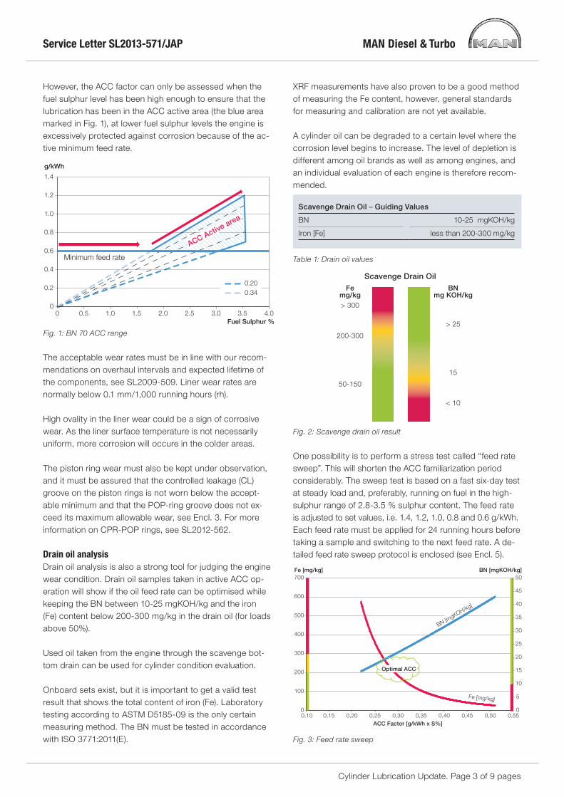
This is illustrated by our feed rate guide, which sets the minimum feed rate to the level needed to keep the parts moving within a safe margin. However, so as to ensure the necessary lubrication effect, an increased formation of acid would call for a higher BN level than specified at the minimum feed rate. This is compensated for by calculating a feed rate on the basis of an ACC factor within the guide shown in Fig. 1.
In order to simplify the lubrication process onboard the ships, as well the logistics of supply, the oil companies have started the process of developing a single-cylinder lube oil that can lubricate the cylinders regardless of the sulphur content in the fuel.
■ Such oils have BN levels that are lower than the tradi-tional BN 70 cylinder lube oils.
■ Such oils have performed acceptably in the service tests carried out.
■ Such oils can very well be used on the vast majority of earlier-type MAN B&W engines that are not affected by cold corrosion, but may not be applicable on newer en-gine designs with higher levels of cold corrosion
MAN Diesel & Turbo recommends using cylinder lube oils characterised primarily by its BN number and SAE viscosity and to use a feed rate according to the BN in the cylinder oil and sulphur content of the fuel. MAN Diesel & Turbo is aware that some engines may be operated satisfactorily at even lower feed rates. Hence, feed rates are, just as before, based on practical experience rather than pre-calculated figures.
The above mirrors the importance of the fact that the crew should challenge the cylinder oil feed rate ACC factor, so as to find the correct ACC value that suits the actual engine configuration and engine load.
Optimising the ACC factorThe best way to establish the optimum ACC factor is to measure the engine wear. If the wear rate of the liner and piston rings is too high, because of corrosion, the ACC fac-tor must be increased to reduce the wear.
We recommend to start out with an ACC factor in the upper end of the range, and then slowly reduce it when the engine wear response has been confirmed by mea-surements.
For more information on condition-based monitoring, we refer to our service letter SL2007-483.
Service Letter SL2013-571/JAP
Cylinder Lubrication Update. Page 3 of 9 pages
However, the ACC factor can only be assessed when the fuel sulphur level has been high enough to ensure that the lubrication has been in the ACC active area (the blue area marked in Fig. 1), at lower fuel sulphur levels the engine is excessively protected against corrosion because of the ac-tive minimum feed rate.
The acceptable wear rates must be in line with our recom-mendations on overhaul intervals and expected lifetime of the components, see SL2009-509. Liner wear rates are normally below 0.1 mm/1,000 running hours (rh).
High ovality in the liner wear could be a sign of corrosive wear. As the liner surface temperature is not necessarily uniform, more corrosion will occure in the colder areas.
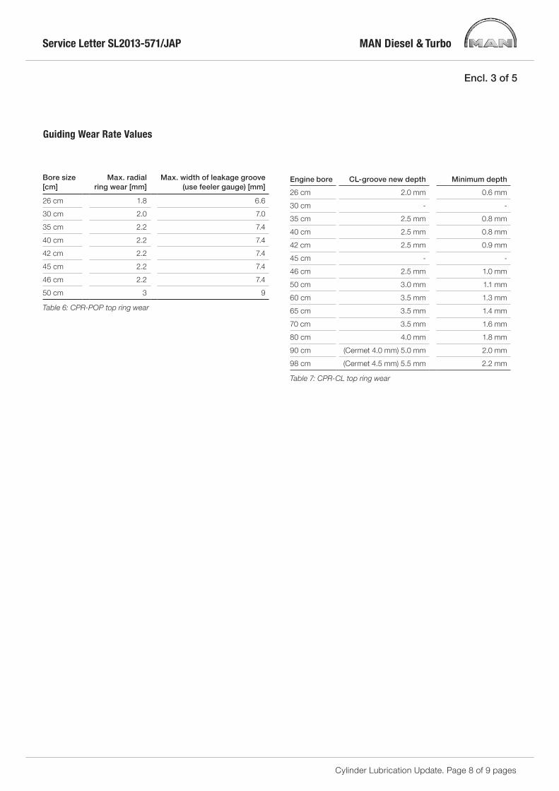
The piston ring wear must also be kept under observation, and it must be assured that the controlled leakage (CL) groove on the piston rings is not worn below the accept-able minimum and that the POP-ring groove does not ex-ceed its maximum allowable wear, see Encl. 3. For more information on CPR-POP rings, see SL2012-562.
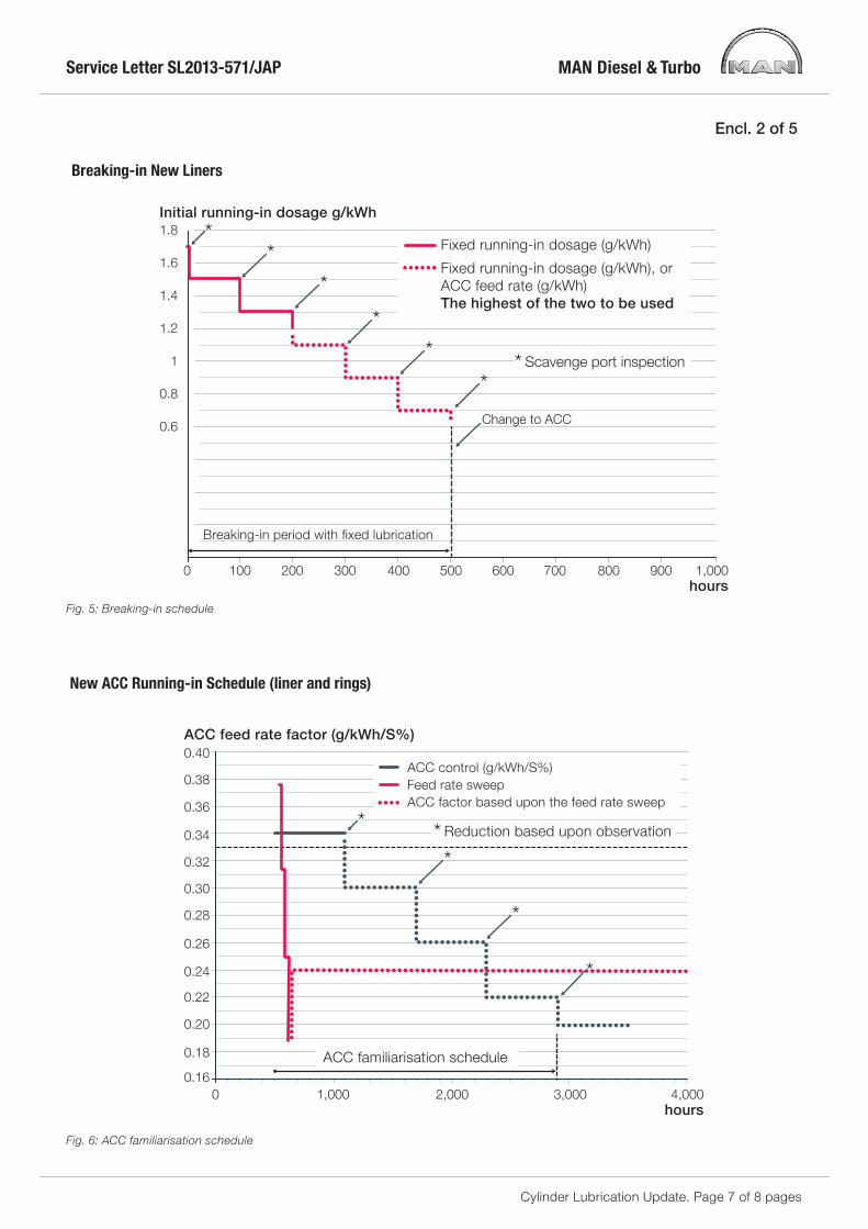
Drain oil analysisDrain oil analysis is also a strong tool for judging the engine wear condition. Drain oil samples taken in active ACC op-eration will show if the oil feed rate can be optimised while keeping the BN between 10-25 mgKOH/kg and the iron (Fe) content below 200-300 mg/kg in the drain oil (for loads above 50%).
Used oil taken from the engine through the scavenge bot-tom drain can be used for cylinder condition evaluation.
Onboard sets exist, but it is important to get a valid test result that shows the total content of iron (Fe). Laboratory testing according to ASTM D5185-09 is the only certain measuring method. The BN must be tested in accordance with ISO 3771:2011(E).
XRF measurements have also proven to be a good method of measuring the Fe content, however, general standards for measuring and calibration are not yet available.
A cylinder oil can be degraded to a certain level where the corrosion level begins to increase. The level of depletion is different among oil brands as well as among engines, and an individual evaluation of each engine is therefore recom-mended.
Scavenge Drain Oil – Guiding Values
BN 10-25 mgKOH/kg
Iron [Fe] less than 200-300 mg/kg
Table 1: Drain oil values
0
0.2
0.4
0.6
0.8
1.0
1.2
1.4
g/kWh
0 0.5 1.0 1.5 2.0 2.5 3.0 3.5 4.0Fuel Sulphur %
ACC Active area
0.20
0.34
Minimum feed rate
Fig. 1: BN 70 ACC range
Scavenge Drain OilFe
mg/kg
50-150
BNmg KOH/kg
200-300
> 300
> 25
15
< 10
Fig. 2: Scavenge drain oil result
Fig. 3: Feed rate sweep
One possibility is to perform a stress test called “feed rate sweep”. This will shorten the ACC familiarization period considerably. The sweep test is based on a fast six-day test at steady load and, preferably, running on fuel in the high-sulphur range of 2.8-3.5 % sulphur content. The feed rate is adjusted to set values, i.e. 1.4, 1.2, 1.0, 0.8 and 0.6 g/kWh. Each feed rate must be applied for 24 running hours before taking a sample and switching to the next feed rate. A de-tailed feed rate sweep protocol is enclosed (see Encl. 5).
BN [mgKOH/kg]
BN [mgKOH/kg]
Optimal ACC
0,10 0,15 0,20 0,25 0,30 0,35 0,40 0,45 0,50 0,55ACC Factor [g/kWh x S%]
0
100
200
300
400
500
600
700Fe [mg/kg]
0
5
10
15
20
25
30
35
40
45
50
Fe [mg/kg]

Service Letter SL2013-571/JAP
Cylinder Lubrication Update. Page 4 of 9 pages
TC cut-out, variable turbine area (VTA) turbocharger, and exhaust gas bypass (EGB), may call for a re-assessment of the ACC factor to accomodate the new corrosion level.
New guiding values New recommendations for standard operation with stan-dard 70 BN cylinder oil. Viscosity range: SAE 40-SAE 50 (SAE 50 for Mk 9 and newer engines).
Guiding values
Base number (BN) 70
SAE 40-50 (50 for Mk 9 and newer)
Guiding minimum feed rate 0.60 g/kWh
ACC range 0.20–0.34 g/kWh x S%
Table 3: Guiding values
Familiarization of the ACC factorAfter the breaking-in period, the engine ACC factor should be assessed over a period of steps of 600 hours (see Fig. 6, Encl. 2).
To be able to asses the engine wear, the steps must be completed with a fuel sulphur content that is high enough to assure that the cylinder oil feed rate is in the ACC active range. This means that the feed rate must be above the minimum 0.60 g/kWh.
Before moving to the next step, the cylinder condition and wear must be assessed through a scavenge port inspection.
In some cases, this familiarization period extends substan-tially. However, the period can be substantially shortened by means of scavenge drain analyses, where the laboratory results will show the remaining BN and Fe (iron) content. If the samples taken during the ACC active feed rates repeat-edly show high BN and acceptable (Fe) levels, the ACC factor can be lowered.
Cylinder oils with different BN levelsThe various oil suppliers offer cylinder oils with a broad range of BN levels. Our MAN B&W engine design is based on the 70 BN oil traditionally used, however, as new oil products have been introduced, BN levels have changed.
When switching to a different BN level, we recommend to start out with scaling the ACC factor from 70 to the new BN level by multiplying the ACC factor with the fraction of 70/BN oil.
Example:Using a BN 45 and ACC (BN 70) = 0.26ACC (BN 45) = 0.26 × 70/45 = 0.40
When changing to a new oil brand or type, the ACC factor may need to be reassessed as described above, starting with an ACC factor in the upper range. After this, a gradual reduction can be carried out based on actual observed conditions or the sweep test.
Low-sulphur HFO and distillatesWhen running on low-sulphur residual fuel (HFO), the feed rate will be set at the minimum feed rate. High-BN cylinder oils will lead to over-additivation in the aspect of controlling the corrosion as well as lead to increased build-up of piston crown deposits.
We therefore recommend switching to a low-BN cylinder oil at the same time as switching to a low-sulphur heavy fuel. Continuous running on high-BN cylinder oils can only be recommended in special cases, and not for more than 1 to 2 weeks.
Also when switching to distillate fuels (MGO/MDO), we rec-ommend switching to a low-BN cylinder oil at the same time as the switching of the fuel. We do not recommend the use of a high-BN cylinder oil when running on distillate fuels.
Table 2: Cylinder oil guide
Part-load operation (slow steaming)When operating the engine at part load, the cold corro-sion behavior may deviate from operation at normal load. When the vessel is slow steaming, the engine is operated at low load, and the liner surface will become cooler and, therefore, increase the risk of corrosion. Waste heat recov-ery and various part-load optimisation possibilities, e.g.
Application BN
Distillate and LNG < = 40
Low-sulphur residual fuel 40-60
High-sulphur residual fuel (70-100 for Mk 9 and newer) 55-100
Fig. 4: Drain oil BN vs. iron (Fe)
500
400
300
200
100
00 10 20 30 40 50 60 70
BN [mgKOH/g]
Danger – Do not operate in this area
Alert area – Adjustment of feed rate may be needed
Safe area
Cat fines
Liner polish
Iron (Fe) total [mg/kg]

Service Letter SL2013-571/JAP
Cylinder Lubrication Update. Page 5 of 9 pages
A feed rate sweep can also be performed to quickly find the correct ACC range for the given engine configuration and load, see Encl. 5.
Running-in operationMAN B&W two-stroke engines require extra attention and lubrication during their first running hours.
The first 500 running hours are the most demanding. This is the period where the liners are run in, which is also re-ferred to as the breaking-in period.
The purpose of the breaking-in period is to flush away wear particles and facilitate running-in of the liner surface and rings.
The breaking-in period is followed by a familiarization pe-riod, where the crew must asses the engine wear and cyl-inder condition to select the right ACC factor for the engine application.
Breaking-in (0-500 rh)Cylinder liner and piston ring breaking-in takes 500 running hours maximum (see Fig. 5, Encl. 2).
During this breaking-in period, the running-in coating on the piston rings will gradually wear off, and the wave cut shape on the cylinder liner surface will smoothen. During this process, extra lubrication oil is required to flush away wear particles and assure a satisfactory oil film between the relatively rough sliding surfaces.
During breaking-in, we recommend checking piston rings and cylinder liners through scavenge air port inspections for every 100 hours. Do not proceed to the next lubrication step if the scavenge air port inspection reveals seizures or other irregularities.
When the steps in the breaking-in reaches 1.20 g/kWh, the feed rate depending on the fuel sulphur content must also be taken into account. The set feed rate is to be the high-est of the two.
Hours g/kWh
0-5 hours 1.70 g/kWh
5-100 hours 1.50 g/kWh
100-200 hours 1.30 g/kWh
200-300 hours 1.10 g/kWh*
300-400 hours 0.90 g/kWh*
400-500 hours 0.70 g/kWh*
* Only if the ACC dependent (fuel sulphur x ACC factor) feed rate is lower than the step, if not then the ACC dependent feed rates are to be used.
Table 4: Breaking-in
Please direct any inquiries and questions regarding tables or condition-based overhaul to our Operation Department at [email protected] or to our Service Department at [email protected].

Service Letter SL2013-571/JAP
Cylinder Lubrication Update. Page 6 of 9 pages
Encl. 1 of 5Guiding cylinder oil feed ratesAll ME/ME-C/ME-B/ME/MC/MC-C and ME-GI enginesWith electronically controlled lubrication system
Standard BN 70
Cylinder oil
Viscosity range SAE 40-50 (SAE 50 for Mk 9 and newer)
ACC setting 0.34 - 0.20
g/kWh x S%
Guiding minimum feed rate 0.60 g/kWh
Maximum feed rate during running-in 1.7 g/kWh
Part-load control Proportional with the load, at lower loads, control is automatically changed to proportional with
rpm.
On Mk 8 and newer, the break point is set at 50% load as default. The break point may be
changed based on actual service experience.
Running-in new or reconditioned liners
and new piston rings
Feed rate:
First 5 hours: 1.7 g/kWh
From 5 to 500 hours: Stepwise reduction from 1.5 - 0.6 g/kWh or ACC factor x fuel
sulphur (using the highest feed rate)
Engine load:
Test bed: Stepwise increase to max. load over 5 hours
In service: 50% to max. load in 16 hours
Familiarizing
ACC Factor
Starting at 0.34 g/kWh x S%
Reducing in steps of 0.04 g/kWh x S% after minimum 600 hours where the feed rate has been
sulphur dependent (above minimum feed rate) or using feed rate sweep or continuous drain oil
analysis
Running-in new rings in already run-in and
well running liners
From 50% to max. load in 5 hours
Feed rate 0.9 g/kWh for 24 hours.
If the fuel sulphur and applied ACC factor combination results in a specific feed rate higher than
0.9 g/kWh (use the calculation feed rate), no extra lubrication is needed.
Manoeuvring and load change
situations
During starting, manoeuvring and load changes, increase feed rate by means of the “LCD” by
25% of the actual figure and kept at this level for ½ hour after the load has stabilised.
Lubrication of cylinders that show
abnormal conditions
Frequent scavenge port inspections of piston rings and cylinder liners are very important for
maintaining a safe cylinder condition.
If irregularities are observed, adjustments of the lube oil feed rate should be considered.
In case of scuffing, sticking piston rings or high liner temperature fluctuations, raise the feed
rate to 1.20 g/kWh and lower the pmax and mep. As soon as the situation has been stabilised,
set the lubrication feed rate and pressures back to normal.
In case of high corrosive wear, the part-load break point from power to rpm is to be set at 50%
load, and the ACC factor is to be increased to the highest ACC factor (0.34 for BN 70) and be
reduced in steps of only 0.02 g/kWh x S% when the wear has been confirmed as normal.
Table 5: Guiding cylinder oil feed rates
Service Letter SL2013-571/JAP
Cylinder Lubrication Update. Page 7 of 8 pages
New ACC Running-in Schedule (liner and rings)
Fig. 6: ACC familiarisation schedule
Fig. 5: Breaking-in schedule
0.16
0.18
0.20
0.22
0.24
0.26
0.28
0.30
0.32
0.34
0.36
0.38
0.40
0 1,000 2,000 3,000 4,000
ACC feed rate factor (g/kWh/S%)
hours
ACC control (g/kWh/S%)Feed rate sweepACC factor based upon the feed rate sweep
* Reduction based upon observation
ACC familiarisation schedule
*
*
*
*
hours
Initial running-in dosage g/kWh
0.6
0.8
1
1.2
1.4
1.6
1.8
0 100 200 300 400 500 600 700 800 900 1,000
Breaking-in period with fixed lubrication
* Scavenge port inspection
Change to ACC
Fixed running-in dosage (g/kWh)
Fixed running-in dosage (g/kWh), or ACC feed rate (g/kWh)The highest of the two to be used
**
*
**
*
Encl. 2 of 5
Breaking-in New Liners
Service Letter SL2013-571/JAP
Cylinder Lubrication Update. Page 8 of 9 pages
Engine bore CL-groove new depth Minimum depth
26 cm 2.0 mm 0.6 mm
30 cm - -
35 cm 2.5 mm 0.8 mm
40 cm 2.5 mm 0.8 mm
42 cm 2.5 mm 0.9 mm
45 cm - -
46 cm 2.5 mm 1.0 mm
50 cm 3.0 mm 1.1 mm
60 cm 3.5 mm 1.3 mm
65 cm 3.5 mm 1.4 mm
70 cm 3.5 mm 1.6 mm
80 cm 4.0 mm 1.8 mm
90 cm (Cermet 4.0 mm) 5.0 mm 2.0 mm
98 cm (Cermet 4.5 mm) 5.5 mm 2.2 mm
Table 7: CPR-CL top ring wear
Bore size [cm]
Max. radial ring wear [mm]
Max. width of leakage groove (use feeler gauge) [mm]
26 cm 1.8 6.6
30 cm 2.0 7.0
35 cm 2.2 7.4
40 cm 2.2 7.4
42 cm 2.2 7.4
45 cm 2.2 7.4
46 cm 2.2 7.4
50 cm 3 9
Table 6: CPR-POP top ring wear
Encl. 3 of 5
Guiding Wear Rate Values
Service Letter SL2013-571/JAP
Cylinder Lubrication Update. Page 9 of 9 pages
Encl. 4 of 5
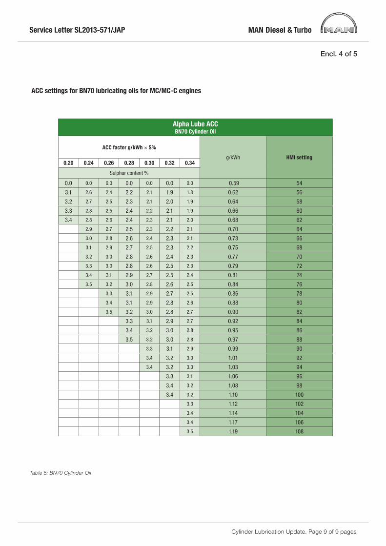
ACC settings for BN70 lubricating oils for MC/MC-C engines
Alpha Lube ACCBN70 Cylinder Oil
ACC factor g/kWh × S%
g/kWh HMI setting0.20 0.24 0.26 0.28 0.30 0.32 0.34
Sulphur content %
0.0 0.0 0.0 0.0 0.0 0.0 0.0 0.59 54
3.1 2.6 2.4 2.2 2.1 1.9 1.8 0.62 56
3.2 2.7 2.5 2.3 2.1 2.0 1.9 0.64 58
3.3 2.8 2.5 2.4 2.2 2.1 1.9 0.66 60
3.4 2.8 2.6 2.4 2.3 2.1 2.0 0.68 62
2.9 2.7 2.5 2.3 2.2 2.1 0.70 64
3.0 2.8 2.6 2.4 2.3 2.1 0.73 66
3.1 2.9 2.7 2.5 2.3 2.2 0.75 68
3.2 3.0 2.8 2.6 2.4 2.3 0.77 70
3.3 3.0 2.8 2.6 2.5 2.3 0.79 72
3.4 3.1 2.9 2.7 2.5 2.4 0.81 74
3.5 3.2 3.0 2.8 2.6 2.5 0.84 76
3.3 3.1 2.9 2.7 2.5 0.86 78
3.4 3.1 2.9 2.8 2.6 0.88 80
3.5 3.2 3.0 2.8 2.7 0.90 82
3.3 3.1 2.9 2.7 0.92 84
3.4 3.2 3.0 2.8 0.95 86
3.5 3.2 3.0 2.8 0.97 88
3.3 3.1 2.9 0.99 90
3.4 3.2 3.0 1.01 92
3.4 3.2 3.0 1.03 94
3.3 3.1 1.06 96
3.4 3.2 1.08 98
3.4 3.2 1.10 100
3.3 1.12 102
3.4 1.14 104
3.4 1.17 106
3.5 1.19 108
Table 5: BN70 Cylinder Oil

MAN Diesel & Turbo
Encl. 5 of 5
HEAD OFFICE (& postal address) MAN Diesel & Turbo Teglholmsgade 41 2450 Copenhagen SV Denmark Phone: +45 33 85 11 00 Fax: +45 33 85 10 30 [email protected] www.mandieselturbo.com
PrimeServ Teglholmsgade 41 2450 Copenhagen SV Denmark Phone: +45 33 85 11 00 Fax: +45 33 85 10 49 [email protected]
PRODUCTION Teglholmsgade 35 2450 Copenhagen SV Denmark Phone: +45 33 85 11 00 Fax: +45 33 85 10 17 [email protected]
FORWARDING & RECEIVING Teglholmsgade 35 2450 Copenhagen SV Denmark Phone: +45 33 85 11 00 Fax: +45 33 85 10 16 [email protected]
MAN Diesel & Turbo Branch of MAN Diesel & Turbo SE, Germany CVR No.: 31611792 Head office: Teglholmsgade 41 2450 Copenhagen SV, Denmark German Reg.No.: HRB 22056 Amtsgericht Augsburg
MAN Diesel & Turbo – a member of the MAN Group
To whom it may concern
LDF1/ JUSV
8 May 2013
The fastest way to evaluate the corrosive behaviour of an engine is to do a stress test, a so called Feed Rate Sweep. It can also be used in the ACC familiarization period in order to find the suitable lube oil feed rate for your particular engine, operating pattern and lube oil used.
During the Sweep-Test, the vessel should be running on fuel with sulphur content above 2.7%. The Sweep-Test takes 6 days and should be performed during a longer voyage were the engine load remains constant and above 25% load under that period. The feed rate of the cylinder oil is set to fixed steps and drain oil samples are taken after 24 hours, before lowering to the next step (Fig. 1).
Fig. 1. Overview of the sweep test procedure
0,4
0,6
0,8
1
1,2
1,4
1,6
0 24 48 72 96 120
Fe
ed
Ra
te (g
/kW
h)
time (hours)
Sweep Test
Drain oil sample
Lube oil sample
Feed Rate Sweep-Test Procedure for Cylinder Oil in MAN B&W Two Stroke Diesel Engines

MAN Diesel & Turbo
- 2 -
Before the test starts a port inspection should be done and samples of the fuel, system oil in use and fresh (unused) cylinder oil should be taken. After the test is finished, all samples should be sent ashore to a certified laboratory. The iron (Fe) content and the BN value should be analyzed. The Fe concentration should be analyzed using the ASTM D5185-09 and the BN should be analyzed using the ISO 3771:2011(E) method. The Fe concentration will be the measurement of corrosion and wear condition. The BN level in the drain oil is an evaluation of the performance of the oil and the need for neutralization in the engine. When the results of the drain oil samples come back you will be able to see if there is any correlation between the ACC factor and Fe and BN.
Test Procedure Day 1(at least 24 hours after departure) Be sure that the correct cylinder oil is bunkered. Adjust the feed rate of the
cylinder oil to 1.4 g/kWh. Write down the following information in the Sweep-test protocol:
a. Name of ship and type of engine b. Date and time of starting the test. c. Name and Brand of the Cylinder oil, BN and SAE viscosity numbers d. Engine load
Day 2 After running 24 h on cylinder oil feed rate of 1.4 g/kWh, drain oil samples to
be taken from all cylinders.
Important: Make sure to flush the drain valve into a bucket before taking the sample. Only use clean bottles, and make sure not to mix drain oil form one unit with another. Mark the bottles with the following information:
a. Cylinder no. b. Date and time c. The name and BN number of the cylinder oil d. Feed rate of cylinder oil e. Engine load Also write down the information in the test protocol. After this, the cylinder oil feed rate should be adjusted to 1.2 g/kWh

MAN Diesel & Turbo
- 3 -
Day 3 After running 24 h on cylinder oil feed rate of 1.2 g/kWh, drain oil samples to
be taken from all cylinders. Sample-procedure same as Day 2. After this, the cylinder oil feed rate should be adjusted to 1.0 g/kWh
Day 4 After running 24 h on cylinder oil feed rate of 1.0 g/kWh, drain oil samples to
be taken from all cylinders. Sample-procedure same as Day 2. After this, the cylinder oil feed rate should be adjusted to 0.8 g/kWh
Day 5 After running 24 h on cylinder oil feed rate of 0.8 g/kWh, drain oil samples to
be taken from all cylinders. Sample procedure same as Day 2. After this, the cylinder oil feed rate should be adjusted to 0.6 g/kWh
Day 6 After running 24 h on cylinder oil feed rate of 0.6 g/kWh, drain oil samples to
be taken from all cylinders. Sample-procedure same as Day 2. After this, the cylinder oil feed rate should be adjusted to the normal ACC factor.

MAN Diesel & Turbo
- 4 -
Sweep-Test Protocol Please fill in the information. After the test, the samples should be sent to a certified laboratory for analysis. Before the test starts a port inspection should be done and samples of the fuel and system oil in use and fresh (unused) cylinder oil should be taken. Use clean bottle and mark them with the information stated on page 2.
Name of Ship:........................................
Engine type:.............................. Load:........
Total running hours:..............................
Name of cylinder oil:....................... BN: ........ SAE Viscosity:................................
Sulphur content in fuel:...............%
Start date and time:....................... End date and time:...............................
Please fill in the Running Hours for the following Cylinder 1 2 3 4 5 6 7 8 9 10 11 12
Cylinder liners
Piston crowns
Piston rings
Fuel valves
Cylinder oil Day 1 Day 2 Day 3 Day 4 Day 5 Day 6Feed rate (g/kWh)
1.4 1.2 1.0 0.8 0.6 Back to normal
Drain oil samples: Use clean bottles and mark them with cylinder nr, date and time, feed rate, engine load, cylinder oil name, BN
Please fill in this table when taking the samples Cylinder 1 2 3 4 5 6 7 8 9 10 11 12
Day 2 Date
Feed rate
Engine load
Day 3 Date
Feed rate
Engine load
Day 4 Date
Feed rate
Engine load
Day 5 Date
Feed rate
Engine load
Day 6 Date
Feed rate
Engine load
MAN Diesel & Turbo
- 5 -
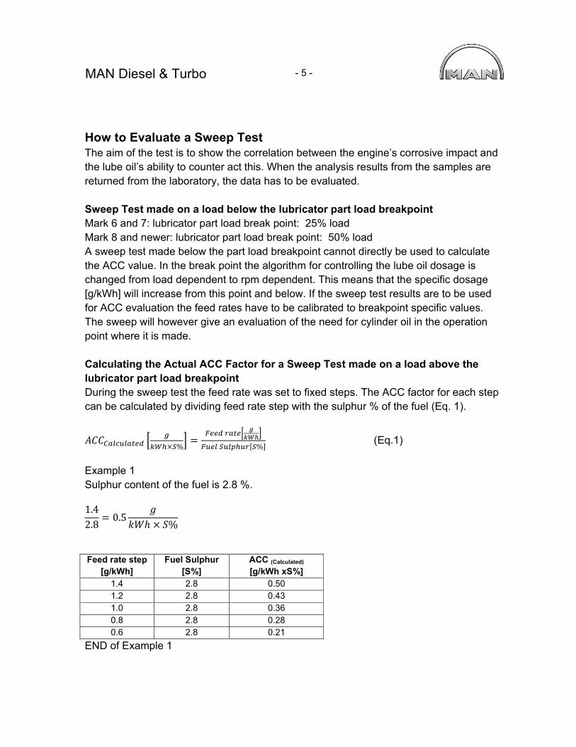
How to Evaluate a Sweep Test The aim of the test is to show the correlation between the engine’s corrosive impact and the lube oil’s ability to counter act this. When the analysis results from the samples are returned from the laboratory, the data has to be evaluated. Sweep Test made on a load below the lubricator part load breakpoint Mark 6 and 7: lubricator part load break point: 25% load Mark 8 and newer: lubricator part load break point: 50% load A sweep test made below the part load breakpoint cannot directly be used to calculate the ACC value. In the break point the algorithm for controlling the lube oil dosage is changed from load dependent to rpm dependent. This means that the specific dosage [g/kWh] will increase from this point and below. If the sweep test results are to be used for ACC evaluation the feed rates have to be calibrated to breakpoint specific values. The sweep will however give an evaluation of the need for cylinder oil in the operation point where it is made. Calculating the Actual ACC Factor for a Sweep Test made on a load above the lubricator part load breakpoint During the sweep test the feed rate was set to fixed steps. The ACC factor for each step can be calculated by dividing feed rate step with the sulphur % of the fuel (Eq. 1).
%
% (Eq.1)
Example 1 Sulphur content of the fuel is 2.8 %. 1.42.8
0.5%
Feed rate step
[g/kWh] Fuel Sulphur
[S%] ACC (Calculated)
[g/kWh xS%] 1.4 2.8 0.50 1.2 2.8 0.43 1.0 2.8 0.36 0.8 2.8 0.28 0.6 2.8 0.21
END of Example 1
MAN Diesel & Turbo
- 6 -
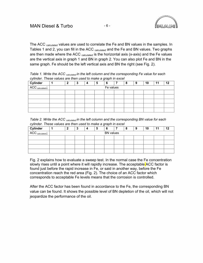
The ACC calculated values are used to correlate the Fe and BN values in the samples. In Tables 1 and 2, you can fill in the ACC calculated and the Fe and BN values. Two graphs are then made where the ACC calculated is the horizontal axis (x-axis) and the Fe values are the vertical axis in graph 1 and BN in graph 2. You can also plot Fe and BN in the same graph. Fe should be the left vertical axis and BN the right (see Fig. 2). Table 1. Write the ACC calculated in the left column and the corresponding Fe value for each cylinder. These values are then used to make a graph in excel Cylinder 1 2 3 4 5 6 7 8 9 10 11 12
ACC calculated↓ Fe values
Table 2. Write the ACC calculated in the left column and the corresponding BN value for each cylinder. These values are then used to make a graph in excel Cylinder 1 2 3 4 5 6 7 8 9 10 11 12
ACC calculated↓ BN values
Fig. 2 explains how to evaluate a sweep test. In the normal case the Fe concentration slowly rises until a point where it will rapidly increase. The acceptable ACC factor is found just before the rapid increase in Fe, or said in another way, before the Fe concentration reach the red area (Fig. 2). The choice of an ACC factor which corresponds to acceptable Fe levels means that the corrosion is controlled. After the ACC factor has been found in accordance to the Fe, the corresponding BN value can be found. It shows the possible level of BN depletion of the oil, which will not jeopardize the performance of the oil.

MAN Diesel & Turbo
- 7 -
Fig. 2. The ACC factor (g/kWhxS%) is shown on the x-axis. The Fe concentration (mg/kg) is depicted with red lines and the result is read on the left y-axis. The axis is divided into three parts. The green bar is showing safe operation condition, 0 - 200 Fe (mg/kg) and the orange bar is the “be alert area”, 200-300 Fe (mg/kg), which means that the cylinder liner and lube oil have started to reach their limits. When the Fe concentration reach above 300 mg/kg (the red bar), the wear or corrosion have started to increase greatly and the lube oil feed rate should be increased.
The rest BN concentration (mg KOH/kg) is depicted with blue lines and the results is read on the right y-axis. The axis is dived into two parts. The red bar (0-10 BN) means that the neutralization ability of lube oil has started to be depleted and the risk of corrosion is increased. The green bar (10 - 50 BN) is showing safe operation.

MAN Diesel & Turbo
- 8 -
The thick blue line and the thick red line are the BN and Fe values from the same sweep. In order to find the correct ACC factor and possible level of BN depletion of the cylinder oil the procedure is as follows: Follow the thick red line and find the Fe concentration for safe operation. In this example it would be 200, because after this the slope of the thick red line is increasing rapidly. The corresponding ACC factor is found on the x-axis and is in this case 0.30 g/kWhxS%. The rest BN value, which corresponds to this safe operation, is found by using BN curve (in this graph, the blue thick line) and read the result of the right x-axis. In this case the ACC factor 0.3 corresponds to 22 BN. The dashed lines are examples of how other sweep tests with other lube oils can look like.