Cygnus M5 ROV Operation Manual
65
Cygnus MINI ROV Mountable and Topside Repeater Systems Operation Manual and Accessories List Doc No. M4-CYGMINI-TSR-M-ENG_Iss 5 August 2019 (Mk4 Cygnus MINI ROV Gauges)
Transcript of Cygnus M5 ROV Operation Manual

Cygnus MINI ROV Mountable and
Topside Repeater Systems
Operation Manual and
Accessories List
Doc No. M4-CYGMINI-TSR-M-ENG_Iss 5 August 2019
(Mk4 Cygnus MINI ROV Gauges)

Cygnus MINI ROV Operation Manual M4-CYGMINI-TSR-M-ENG_Iss 5.docx
Page 2 of 65
Contents
1. Introduction ...................................................................... 6
CYGNUS MINI ROV Mountable Ultrasonic Thickness Gauge ...........6
Multiple Echo Measurements ...................................................7
Triple Echo Verification ........................................................7
Cygnus Instruments ...............................................................8
2. Gauge Kit Contents ........................................................... 9
Data Conversion Items ......................................................... 10
Top Side Repeater (TSR) Remote Display Unit with Video On-
Screen-Display (OSD) .......................................................... 11
3. Gauge Preparation .......................................................... 12
Fitting the Probe-module ...................................................... 12
Underwater Cable connection to the Gauge .............................. 13
Electrical connections to the Gauge ........................................ 14
Power Supply ................................................................... 14
Data Output ..................................................................... 14
Electrical connections to the Surface ....................................... 15
Connection to a Computer .................................................. 15
Connection to the ROV Craft ............................................... 15
Custom Connection ........................................................... 15
Custom Display Software ................................................... 15
Measuring Through a Water Gap ............................................ 16
4. Displaying the Thickness Measurements ......................... 17
Data Logging ...................................................................... 17
Video Overlay ..................................................................... 17
5. Calibration ...................................................................... 18
6. Using the TSR Remote Display Unit ................................. 19
Turning the Unit On ............................................................. 19
Changing the Displayed Units ................................................ 19
Setting the Velocity of Sound ................................................ 19
Calibrating to a Known Thickness using a TSR .......................... 20
Display Hold Function ........................................................... 20
Automatic Display Backlight .................................................. 20
Video Overlay Facility ........................................................... 20
Connecting the Video Signal ............................................... 21
Positioning the On-Screen Display (OSD) .............................. 21
Testing the Link ................................................................... 22

M4-CYGMINI-TSR-M-ENG_Iss 5.docx Cygnus MINI ROV Operation Manual
Page 3 of 65
Troubleshooting - Error Messages .......................................... 22
7. CygLink Surface Display and Control Kit ......................... 23
Kit Contents ........................................................................ 23
Connection Diagram ............................................................. 24
Connector Details and Signals ............................................... 24
Installing CygLink ................................................................ 24
COM Port Numbers .............................................................. 25
Setting the COM Port Manually ............................................ 25
Finding your COM Port Number ........................................... 25
To Change the COM Port number assigned by Windows® ........... 26
Opening Device Manager .................................................... 26
Running CygLink Application .................................................. 28
Connecting to the ROV Gauge ................................................ 28
Changing Gauge Settings ...................................................... 29
Material Velocity List ......................................................... 29
Calibrating to a Known Thickness using CygLink ....................... 30
CygLink Surveys and Data Logging ......................................... 31
Editing the Survey Details .................................................. 32
Editing the Survey Group Details ......................................... 32
Reference and Minimum Thickness Criteria ........................... 33
Producing a Survey Report Document .................................. 33
Logging Measurements Directly in CygLink .............................. 33
Pre-Set Measurement Comments List ................................... 33
Adding Comments or Notes to a Measurement....................... 34
CygLink Trouble Shooting ..................................................... 35
Connection Problems – USB Drivers ..................................... 35
Wiring Problems ............................................................... 35
8. Probes & Membranes ...................................................... 36
Probe Selection ................................................................... 36
Changing the Membrane ....................................................... 37
Probe Selection & Specifications ............................................. 38
Probe Frequency Identification ............................................... 38
Mounting the Ultrasonic Probe ............................................... 39
9. O-Ring Seals ................................................................... 40
Correct fitting of O-ring seals ................................................ 40
Removing the Nosecone ....................................................... 41
Replacing the O-Ring Seals ................................................... 42
Checking the O-rings ............................................................ 42
10. General Points on Thickness Gauging .......................... 44

Cygnus MINI ROV Operation Manual M4-CYGMINI-TSR-M-ENG_Iss 5.docx
Page 4 of 65
11. Troubleshooting ........................................................... 45
Difficulty obtaining a Reading ................................................ 45
If Readings are Erratic or Unstable ......................................... 45
12. The 3 Point Check ........................................................ 46
13. Care and Servicing ....................................................... 47
Cleaning the Gauge .............................................................. 47
Use of O-Rings .................................................................... 47
Data-link connector.............................................................. 47
Environmental ..................................................................... 48
Repairs .............................................................................. 48
Returning the Gauge for Servicing .......................................... 48
14. Information ................................................................. 49
Technical Specifications ........................................................ 49
15. Serial Data Format ....................................................... 50
Protocol ............................................................................. 50
Valid Thickness Measurement Packet Arrangement ................. 50
No Thickness Measurement Packet Arrangement .................... 50
Status-byte Structure ........................................................ 51
Data-bytes Arrangement .................................................... 51
Interpreting the Readings sent from the Gauge ..................... 52
16. Table of Sound Velocities ............................................. 53
Reading Conversions ......................................................... 54
17. Part Number & Accessories List ................................... 55
Software ............................................................................ 55
Underwater Probes with 1 Metre Lead ..................................... 55
Probe Spares and Membranes ................................................ 56
Knurled Rings ..................................................................... 57
Cables and Leads ................................................................. 57
Electronic Bodies Only .......................................................... 57
Miscellaneous Spares ........................................................... 57
18. Recycling and Disposal (EC Countries)......................... 59
19. Warranty Information .................................................. 60
20. Pressure Test Statement .............................................. 61
21. Independent Cable Connection .................................... 62
Recommended cable connection for direct cabling from Cygnus MINI ROV Gauge to surface computer ..................................... 62
22. ROV-Local Termination Connection .............................. 63

M4-CYGMINI-TSR-M-ENG_Iss 5.docx Cygnus MINI ROV Operation Manual
Page 5 of 65
Recommended cable connection from Cygnus MINI ROV Gauge to
ROV craft ........................................................................... 63
Recommended connection at surface, taken from ROV cabling to computer ........................................................................... 64
23. Index ........................................................................... 65

Cygnus MINI ROV Operation Manual M4-CYGMINI-TSR-M-ENG_Iss 5.docx
Page 6 of 65
1. Introduction
CYGNUS MINI ROV Mountable Ultrasonic Thickness
Gauge
The Cygnus MINI ROV Mountable Ultrasonic Thickness Gauge (Cygnus MINI ROV Gauge) is designed for high-reliability thickness measurement using the Multiple-Echo technique. The Gauge is a lightweight gauge designed to be mounted on smaller submersible ROV craft.
Fully-waterproof, the Cygnus MINI ROV Gauge can be used both underwater and in air and is pressure tested to 500 metres’ water depth. It is supplied with dedicated PC-software for displaying and logging thickness readings at the surface. The Gauge is supplied with one ultrasonic Probe. The Probe type must be specified at the time of purchase of the Gauge. Probes are not freely interchangeable – please consult with Cygnus if you wish to use a different Probe with the Gauge.
The Gauge is a solid-state electronic instrument which, under normal operating conditions, will give many years of active service. Although designed for ease of operation, first time users should carefully read this manual to familiarise themselves with the features of the Gauge.
M4-CYGMINI-TSR-M-ENG_Iss 5.docx Cygnus MINI ROV Operation Manual
Page 7 of 65
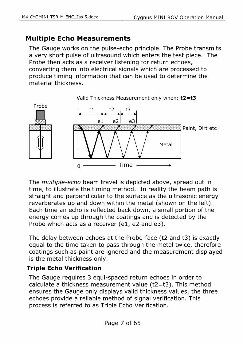
Multiple Echo Measurements
The Gauge works on the pulse-echo principle. The Probe transmits a very short pulse of ultrasound which enters the test piece. The Probe then acts as a receiver listening for return echoes, converting them into electrical signals which are processed to produce timing information that can be used to determine the material thickness.
The multiple-echo beam travel is depicted above, spread out in time, to illustrate the timing method. In reality the beam path is straight and perpendicular to the surface as the ultrasonic energy reverberates up and down within the metal (shown on the left). Each time an echo is reflected back down, a small portion of the energy comes up through the coatings and is detected by the Probe which acts as a receiver (e1, e2 and e3). The delay between echoes at the Probe-face (t2 and t3) is exactly equal to the time taken to pass through the metal twice, therefore coatings such as paint are ignored and the measurement displayed
is the metal thickness only.
Triple Echo Verification
The Gauge requires 3 equi-spaced return echoes in order to calculate a thickness measurement value (t2=t3). This method ensures the Gauge only displays valid thickness values, the three echoes provide a reliable method of signal verification. This process is referred to as Triple Echo Verification.
e1 e2 e3
t2 t3
Valid Thickness Measurement only when: t2=t3
Time
Paint, Dirt etc
Metal
0
t1 Probe

Cygnus MINI ROV Operation Manual M4-CYGMINI-TSR-M-ENG_Iss 5.docx
Page 8 of 65
CYGNUS Singapore (S) Pty. Ltd. 63 Jalan Pemimpin #05-01,
Pemimpin Industrial Building. 577219 Singapore.
Tel : (+65) 6252 5909
Fax : (+65) 6251 1318 www.cygnus-instruments.sg
Cygnus UAE
Cygnus Instruments Middle East P.O. Box 127267
Jebel Ali Free Zone (JAFZA)
Dubai UAE
Website: www.cygnus-instruments.com Telephone: +971 50 3459305
E-mail: [email protected]
Cygnus Instruments
Cygnus Instruments Limited, founded in 1983, pioneered the development of the Digital Ultrasonic Multiple-Echo Technique used for measurement through coatings. This has long since been the standard required to ensure that accurate measurements are taken without the need to zero the Gauge or remove any coatings first. Our philosophy is to work closely our customers to provide high quality products, engineered to serve heavy industry & harsh
environments. Cygnus Ultrasonic thickness gauges are designed to be reliable and simple to use. We have an unrivalled reputation in over 45 countries around the world.
CYGNUS Instruments Inc. Phillips Hwy Commerce Park
6900 Phillips Hwy, Suite 8 Jacksonville, FL 32216
Tel: 00 1 410 267 9771 Fax: 00 1 410 268 2013
www.cygnusinstruments.com
CYGNUS Instruments Ltd.
Cygnus House, 30 Prince of Wales Road, Dorchester, Dorset, DT1 1PW England.
Website: www.cygnus-instruments.com Tel: 00 44 (0) 1305 265533
Fax: 00 44 (0) 1305 269960

M4-CYGMINI-TSR-M-ENG_Iss 5.docx Cygnus MINI ROV Operation Manual
Page 9 of 65
2. Gauge Kit Contents
1. Cygnus MINI ROV Gauge Body
2. Nose Cone Torque Bar
3. Operation Manual & CygLink Software on USB Flash Drive (Not Shown)
4. Bottle of Membrane Couplant
5. Carry Case
6. Test Lead
7. 9 Way D-Type Connector
8. Impulse Plug to Fly Leads
9. Impulse Blanking Plug
16/17

Cygnus MINI ROV Operation Manual M4-CYGMINI-TSR-M-ENG_Iss 5.docx
Page 10 of 65
10. 10 x ‘B/D’ O Rings
11. 10 x ‘A’ O Rings
12. Silicone Grease
13. K3 RS-422/485 to RS-232 Converter
14. RS-232 to USB Converter
15. K3 Manual, Documents and Warranty Letter
16. Probe Assembly, including:
17. Spare Membranes and Membrane Key
18. Sample Test Block
Data Conversion Items
Connection to USB is an RS232-to-USB Adaptor, as included in the main kit contents. This USB-to-Serial Adaptor is used together with the RS422-to-RS232 Converter as shown:
1. RS-232 to USB Converter Module & Cable
2. ‘K3’ RS-422/485 to RS-232 Converter Module
3. Connection from ROV subsea link
1 2
3

M4-CYGMINI-TSR-M-ENG_Iss 5.docx Cygnus MINI ROV Operation Manual
Page 11 of 65
Top Side Repeater (TSR) Remote Display Unit with
Video On-Screen-Display (OSD)
The Cygnus TSR Display unit with OSD is an Optional Accessory to the main Gauge Kit.
It is supplied with:
1. Protective silicone sleeve
2. 12V DC power supply UK/EU/US
3. BNC to BNC cable x 2
4. BNC Jack to Phono plug
5. BNC Plug to Phono socket
6. 9-way D to Lemo link lead
Cygnus MINI ROV Operation Manual M4-CYGMINI-TSR-M-ENG_Iss 5.docx
Page 12 of 65
3. Gauge Preparation The Gauge is supplied ready to use, once the probe-module has been attached to it. All that is required is to make the necessary electrical connections between the Gauge and the ROV Craft and the chosen topside display. There are no controls or display on the gauge. Calibration is performed at the surface using the top side display.
Fitting the Probe-module
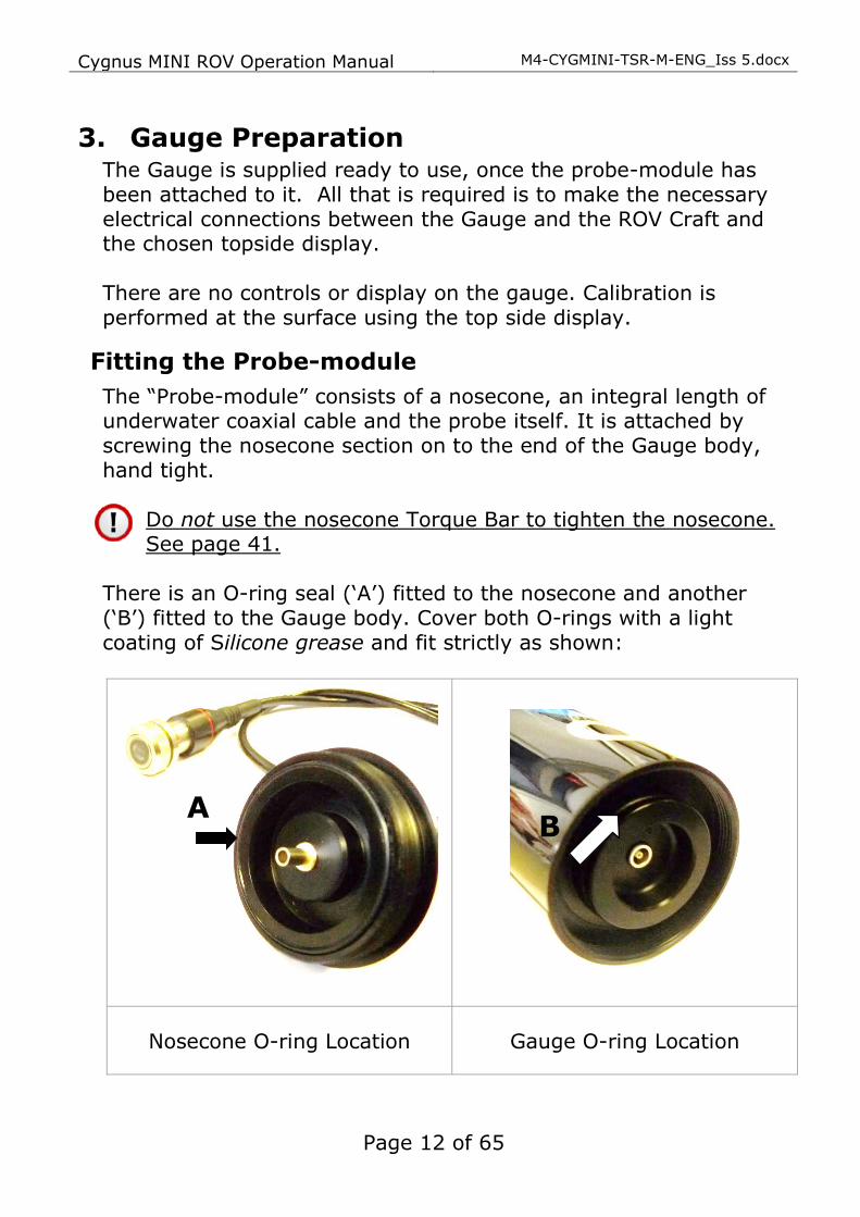
The “Probe-module” consists of a nosecone, an integral length of underwater coaxial cable and the probe itself. It is attached by screwing the nosecone section on to the end of the Gauge body, hand tight.
Do not use the nosecone Torque Bar to tighten the nosecone. See page 41.
There is an O-ring seal (‘A’) fitted to the nosecone and another (‘B’) fitted to the Gauge body. Cover both O-rings with a light
coating of Silicone grease and fit strictly as shown:
Nosecone O-ring Location Gauge O-ring Location
B A

M4-CYGMINI-TSR-M-ENG_Iss 5.docx Cygnus MINI ROV Operation Manual
Page 13 of 65
It is important to ensure that the O-Rings are properly
located. Incorrect fitting of O-rings, as shown below, will result in the instrument leaking.
Incorrect Location of Nosecone ‘A’ O-ring
Both O-Rings must be replaced after every job or submersion. See page 42.
Underwater Cable connection to the Gauge
The Cygnus MINI ROV Gauge is provided with a fully-waterproof
external (“Impulse”) cable connection. To maintain the integrity of the electrical operation and watertight-seal it is essential that these precautions are observed: Cable connection should only ever be made in dry, ambient
conditions at the surface. Connections must never be made, or broken, underwater
Both the male underwater cable Connector and the Blanking-
plug should have Silicone grease smeared on the pins before inserting into the female socket-connector on the Gauge
The male plug-connector should be pushed fully into the female
socket-connector, and then the rubber retaining-loop should be pushed into the groove on the male-connector to complete the fully-waterproof connection
Wrong

Cygnus MINI ROV Operation Manual M4-CYGMINI-TSR-M-ENG_Iss 5.docx
Page 14 of 65
A Blanking-plug is supplied for use: For safety we recommend that the Blanking Plug is fitted at all times when there is no cable attached to the Gauge body
Electrical connections to the Gauge
See pages 62, 63 & 64 for schematic connection details.
Power Supply
The Gauge requires a DC supply voltage between 7.5 and 30 volts. There is an internal 1 amp fuse and crowbar circuit to protect the instrument from over-voltage surges. The supply input is also protected against accidental reverse polarity connection. There is no ON/OFF switch. The Gauge will operate continuously whilst power is connected. There will be an initial delay of about 2 seconds, and then the instrument will begin continuously transmitting thickness-measurement data. A “Test-Cable” is supplied in the main Gauge Kit, which can be
used to verify the Gauge operation. If you are using the Test-Cable, connect Red to positive and Black to negative.
Data Output
The Gauge outputs its status and thickness measurements as RS-422 serial data. The RS-422 output option can transmit the serial data up to 1200 m (4,000 ft) along a twisted pair cable. The serial
Cygnus MINI ROV Gauge Body
Blanking Plug

M4-CYGMINI-TSR-M-ENG_Iss 5.docx Cygnus MINI ROV Operation Manual
Page 15 of 65
output drivers have ESD protection to ±15 kV. See Serial Data
Format on Page 50.
Electrical connections to the Surface
Connection to a Computer
A single “umbilical” cable can connect the Gauge to the surface, independent of the ROV craft’s own cabling. See page 62. This has a maximum length of 1000 metres. This cable can be supplied, on request, by Cygnus.
As shown on page 9, assemble the data conversion items:
9-way D-connector (on the umbilical cable) to the K3 interface adapter (at the end marked RS422)
the other end of the K3 (marked RS232) can either connect to a free RS-232 serial port on your computer or to the Serial-to-USB adaptor, which can connect to a spare USB port on your computer.
Connection to the ROV Craft
In this method the connection from the Gauge is taken to the ROV craft itself and is merged with the ROV’s own cabling to connect to the surface. See pages 63 and 64. Power for the Gauge can be taken from the ROV’s own power supply, if suitable. It is essential that the data connections from the Gauge are maintained throughout as twisted-pair.
If the distance from the Gauge to the surface is greater than 1000 metres the Data-output from the Gauge must be electronically buffered within the ROV.
Custom Connection
If you intend to convert the serial data sent from the Cygnus MINI ROV Gauge using your own electronics: the TX+ / TX- data-pair may be connected directly to any RS-422 compatible receiving equipment.
Custom Display Software
For Users who wish to develop their own display software: the format of the data sent from the Gauge is detailed in Serial Data Format, page 50.

Cygnus MINI ROV Operation Manual M4-CYGMINI-TSR-M-ENG_Iss 5.docx
Page 16 of 65
Measuring Through a Water Gap
In ROV applications the water can be considered to be a coating. Thus it is possible to measure steel thickness through a small water gap between the probe and the material under inspection. As the Velocity of Sound for seawater is approximately 1500m/s this equates to a maximum seawater gap of 1.3mm.

M4-CYGMINI-TSR-M-ENG_Iss 5.docx Cygnus MINI ROV Operation Manual
Page 17 of 65
4. Displaying the Thickness Measurements The Gauge transmits thickness measurement data to the surface as serial data. To display the thickness value and provide a means of calibration, two options are provided:
1. Using a Cygnus Top-Side Repeater (TSR) unit
2. Using a computer with CygLink software
It is also possible for a third party application to read the serial data and process the thickness measurement data. For more information on the Serial Data Format, to enable use of your own software, see page 50.
Data Logging
The CygLink software also provides the facility to Data Log the thickness measurements as they are taken and to generate a report document for the survey.
Video Overlay
The optional TSR unit has a Video Overlay or On-Screen Display facility where the thickness measurements can be superimposed
on to a video signal feed before the monitor and/or video recorder. The video overlay will work with PAL or NTSC video signals.

Cygnus MINI ROV Operation Manual M4-CYGMINI-TSR-M-ENG_Iss 5.docx
Page 18 of 65
5. Calibration The Gauge is supplied tested and calibrated. The Gauge will have been calibrated to measure thickness through steel (grade S355JO). Either a 15mm or ½” test block is supplied with the kit so the Gauge can be quickly checked for correct operation. Note, this test block is not intended to be used for calibration of the Gauge and may not indicate an exact 15.00 mm.
The best way to calibrate the Gauge is to calibrate using a Known Thickness of a sample piece of the material you intend to measure. This method determines the velocity of sound for the material sample, which will always be more accurate than using a ‘general’ velocity value.
For calibration instructions using CygLink see Calibrating to a Known Thickness using CygLink on page 30, or with the TSR see Calibrating to a Known Thickness using a TSR on page 20.
If there is no test sample available the Gauge can be calibrated by setting the Velocity of Sound directly. A table on page 53 lists common materials and their velocity of sound values. For instructions on setting the velocity of sound using CygLink see page 30, or with the TSR see page 19. A third method is to leave the Gauge set to its factory-preset value for Steel [5920 m/s or 0.2332 in/us], and then use a Conversion Factor from the table of velocities on page 53.

M4-CYGMINI-TSR-M-ENG_Iss 5.docx Cygnus MINI ROV Operation Manual
Page 19 of 65
6. Using the TSR Remote Display Unit The Cygnus Top Side Repeater (TSR) is a small handheld display unit that can display the thickness measurement values from the Gauge on its LCD display. It provides the ability to calibrate the Gauge’s output to suit the material or to a specific velocity of sound. A video overlay facility is also included, which allows the thickness measurements to be superimposed on to a video signal before the monitor or video recording device.
Turning the Unit On
1. Press the red ON key
2. The Cygnus Logo screen appears
3. If not connected to a Gauge the display shows “NO CONNECTION” This is normal – it just means no data has being received yet
Changing the Displayed Units
1. Press the MENU key to display the MENU
2. Press the DOWN ARROW key to scroll down to UNITS the current units are displayed
3. Press the EDIT key to toggle between mm and Inch
Setting the Velocity of Sound
The velocity of sound value is displayed at the top of the screen in either m/s or inch/us.
1. Press the MENU key to display the MENU
2. The VELOCITY menu option should be selected at the top
3. Press the EDIT key to adjust the velocity of sound value Press the OK key to save and exit

Cygnus MINI ROV Operation Manual M4-CYGMINI-TSR-M-ENG_Iss 5.docx
Page 20 of 65
Calibrating to a Known Thickness using a TSR
The TSR display can be calibrated to a known thickness by using the Gauge to measure a sample of the material that will be measured. This method ensures the velocity of sound is set for the actual material being measured rather than using a “generic” value.
1. Place and hold the Gauge’s ultrasonic probe on the material sample, using couplant if out of the water
You should have a stable thickness measurement on the display
2. Press the MENU key to display the MENU
3. The CALIBRATE menu option should be selected at the top
4. Press the EDIT key to adjust the measurement value to the known thickness of the sample being measured Press the OK key to save and exit
5. Repeat from step 1 to check the calibration is stable.
Display Hold Function
The middle key HOLD can be used to freeze the display and hold the current thickness measurement.
1. Press the HOLD key to freeze the display
2. Press the HOLD key again to un-freeze the display
Automatic Display Backlight
The display backlight automatically turns off in bright light conditions, it will automatically turn on when the ambient light level drops.
Video Overlay Facility
The TSR can superimpose the thickness measurement on to a video signal to display it on the monitor screen, and also on the

M4-CYGMINI-TSR-M-ENG_Iss 5.docx Cygnus MINI ROV Operation Manual
Page 21 of 65
video recording of the survey. This provides a thickness
measurement that can be linked to a position or place in the video.
Connecting the Video Signal
The TSR has two BNC sockets on its top panel; Video In and Video Out. The video feeds to the monitor and video recorder is fed through the TSR. The TSR will automatically detect and adjust for PAL or NTSC video signals, it will work with colour or monochrome images.
Positioning the On-Screen Display (OSD)
Because there is usually other information displayed on the video screen the TSR has the facility to move the thickness measurement display ‘box’ anywhere on the screen using X, Y coordinates. The position selected will be stored in the TSR memory during power off.
Sub-sea Camera feed
28.10 mm
5920 m/s
Video
In Video
Out
Monitor &
Video Recorder
28.10 mm
5920 m/s
28.10 mm
5920 m/s

Cygnus MINI ROV Operation Manual M4-CYGMINI-TSR-M-ENG_Iss 5.docx
Page 22 of 65
1. Press the MENU key to display the MENU
2. Press the DOWN ARROW key to scroll down to
OSD X POS
3. Press EDIT to adjust the X screen position Press EXIT to save and exit
4. Press the DOWN ARROW key to scroll down to OSD Y POS
5. Press EDIT to adjust the Y screen position Press EXIT to save and exit
6. Press EXIT again to exit the menu screen
Testing the Link
Before use on a job it is recommended to test the link between the Gauge and the TSR. To do this simply power on both the TSR display and the gauge then measure the test block – the TSR should display the correct test block thickness.
Troubleshooting - Error Messages
1. NO CONNECTION
The TSR has not received any valid data since power-up
Check that the Gauge is turned-on and displaying either a measurement or the echo strength bar-chart Check all cable connections are secure
28.10 mm
5920 m/s
X
Y

M4-CYGMINI-TSR-M-ENG_Iss 5.docx Cygnus MINI ROV Operation Manual
Page 23 of 65
7. CygLink Surface Display and Control Kit
CygLink is a Windows® application for PCs that allows remote viewing, control and data logging for the Cygnus MINI ROV gauge. The software can provide the following functionality:
1. Surface display of thickness measurements
2. Remote setting of the velocity of sound
3. Remote setting of the units
4. Data Logging of thickness measurements into a Survey report
It should be noted that although Cyglink supports A-Scan, the Cygnus MINI ROV Gauge does not.
Kit Contents
The CygLink kit comprises the following items:
1. USB-RS485/RS422 Converter Cable
2. CygLink Software Installer on USB Flash Drive
You will also need an Umbilical cable and connectors to connect the Cygnus MINI ROV Gauge to the top side. Cygnus can supply the complete umbilical cable with connectors fitted, or the customer can make their own umbilical cable using connectors supplied with cable tails/flying leads.

Cygnus MINI ROV Operation Manual M4-CYGMINI-TSR-M-ENG_Iss 5.docx
Page 24 of 65
Connection Diagram
Connector Details and Signals
See page 62 for wiring details.
Installing CygLink
CygLink is supplied on a USB Flash Drive or can be downloaded from a web link emailed from Cygnus Instruments. Installation of CygLink follows normal software installation conventions after running the setup.exe program and following instructions. To install from a flash drive, connect it to a free USB port on your computer. Navigate to the flash drive in Windows® Explorer and open the folder present in the root of the drive. Run the
application named setup.exe to begin the installation process. You will need to accept the End User Licence Agreement in order to complete the installation and a summary of its terms is provided at the start. We advise opting for the Typical setup option for the smoothest installation experience.
MINI ROV
Gauge
Umbilical Cable 1 twisted pair + screen
(1000m max length)
USB-RS422
Converter
Computer with
CygLink

M4-CYGMINI-TSR-M-ENG_Iss 5.docx Cygnus MINI ROV Operation Manual
Page 25 of 65
COM Port Numbers
CygLink should automatically find the COM port number assigned to the USB converter when you click “Connect”, “Discover New Gauge and Connect” so you don’t need to search for the port number Windows has assigned.
Setting the COM Port Manually
If CygLink fails to locate the correct COM port number you can set in manually from the File -> Communications Options menu item. Just tick the Manual Setup box and select the correct COM
port number.
Finding your COM Port Number
With the USB-RS485 Converter plugged into your computer, open Windows Device Manager – to do this press the Windows® key and the ‘R’ key together, then type “devmgmt.msc” into the prompt followed by enter key. In the Ports section, look for the USB Serial Port entry. Remember the COM number listed, as this will need to be selected within CygLink’s settings menu.
Windows® Device Manager
Cygnus MINI ROV Operation Manual M4-CYGMINI-TSR-M-ENG_Iss 5.docx
Page 26 of 65
To Change the COM Port number
assigned by Windows®
Depending on a variety of factors, Windows® may sometimes assign a COM Port number that is too high or unusual to be easily remembered. You may change the number assigned to the port by following these steps:
Opening Device Manager
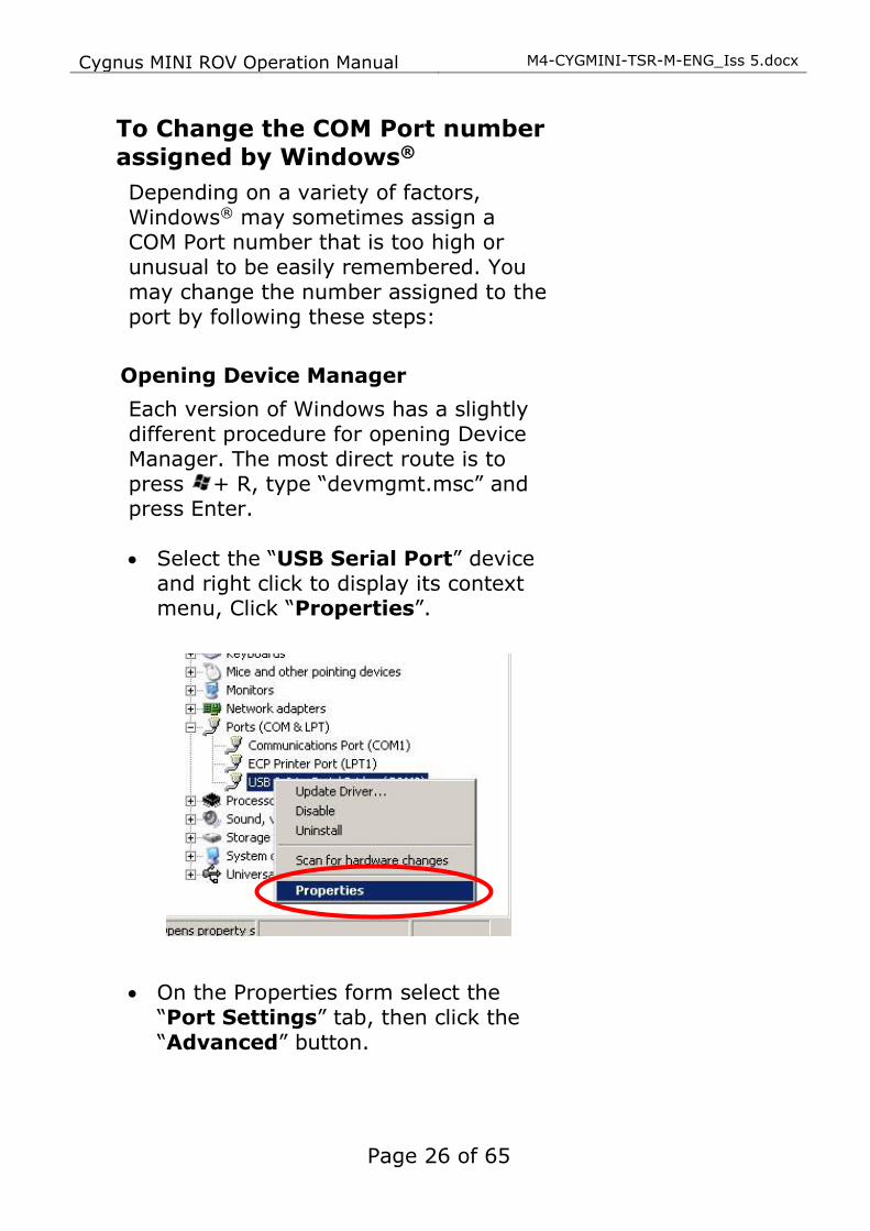
Each version of Windows has a slightly different procedure for opening Device Manager. The most direct route is to press + R, type “devmgmt.msc” and press Enter. • Select the “USB Serial Port” device
and right click to display its context menu, Click “Properties”.
• On the Properties form select the “Port Settings” tab, then click the “Advanced” button.

M4-CYGMINI-TSR-M-ENG_Iss 5.docx Cygnus MINI ROV Operation Manual
Page 27 of 65
• On the “Advanced Settings” form you can change the COM Port number. Finish by clicking the “OK” button.
Cygnus MINI ROV Operation Manual M4-CYGMINI-TSR-M-ENG_Iss 5.docx
Page 28 of 65
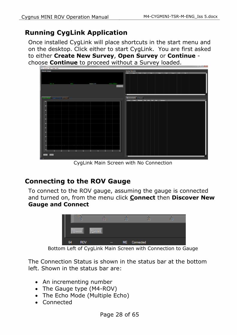
Running CygLink Application
Once installed CygLink will place shortcuts in the start menu and on the desktop. Click either to start CygLink. You are first asked to either Create New Survey, Open Survey or Continue - choose Continue to proceed without a Survey loaded.
CygLink Main Screen with No Connection
Connecting to the ROV Gauge
To connect to the ROV gauge, assuming the gauge is connected and turned on, from the menu click Connect then Discover New Gauge and Connect
Bottom Left of CygLink Main Screen with Connection to Gauge
The Connection Status is shown in the status bar at the bottom left. Shown in the status bar are:
• An incrementing number • The Gauge type (M4-ROV) • The Echo Mode (Multiple Echo) • Connected
M4-CYGMINI-TSR-M-ENG_Iss 5.docx Cygnus MINI ROV Operation Manual
Page 29 of 65
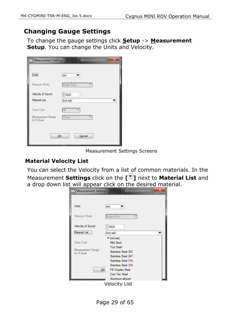
Changing Gauge Settings
To change the gauge settings click Setup -> Measurement Setup. You can change the Units and Velocity.
Measurement Settings Screens
Material Velocity List
You can select the Velocity from a list of common materials. In the
Measurement Settings click on the [ ] next to Material List and a drop down list will appear click on the desired material.
Velocity List

Cygnus MINI ROV Operation Manual M4-CYGMINI-TSR-M-ENG_Iss 5.docx
Page 30 of 65
Calibrating to a Known Thickness using CygLink
The CygLink display can be calibrated to a known thickness by using the Gauge to measure a sample of the material that will be measured. This method ensures the velocity of sound is set for the actual material being measured rather than using a “generic” value.
1. Place and hold the Gauge’s ultrasonic probe on the material sample using couplant if out of the water
You should have a stable thickness measurement on the display
2. Click Setup -> Calibrate Thickness Measurement. With the probe still held on the material sample.
Calibration Menu
3. Select the value in the Thickness box and enter the known thickness of the sample being measured Press the Set and then Save
4. Repeat from step 1 to check the calibration is stable.
M4-CYGMINI-TSR-M-ENG_Iss 5.docx Cygnus MINI ROV Operation Manual
Page 31 of 65
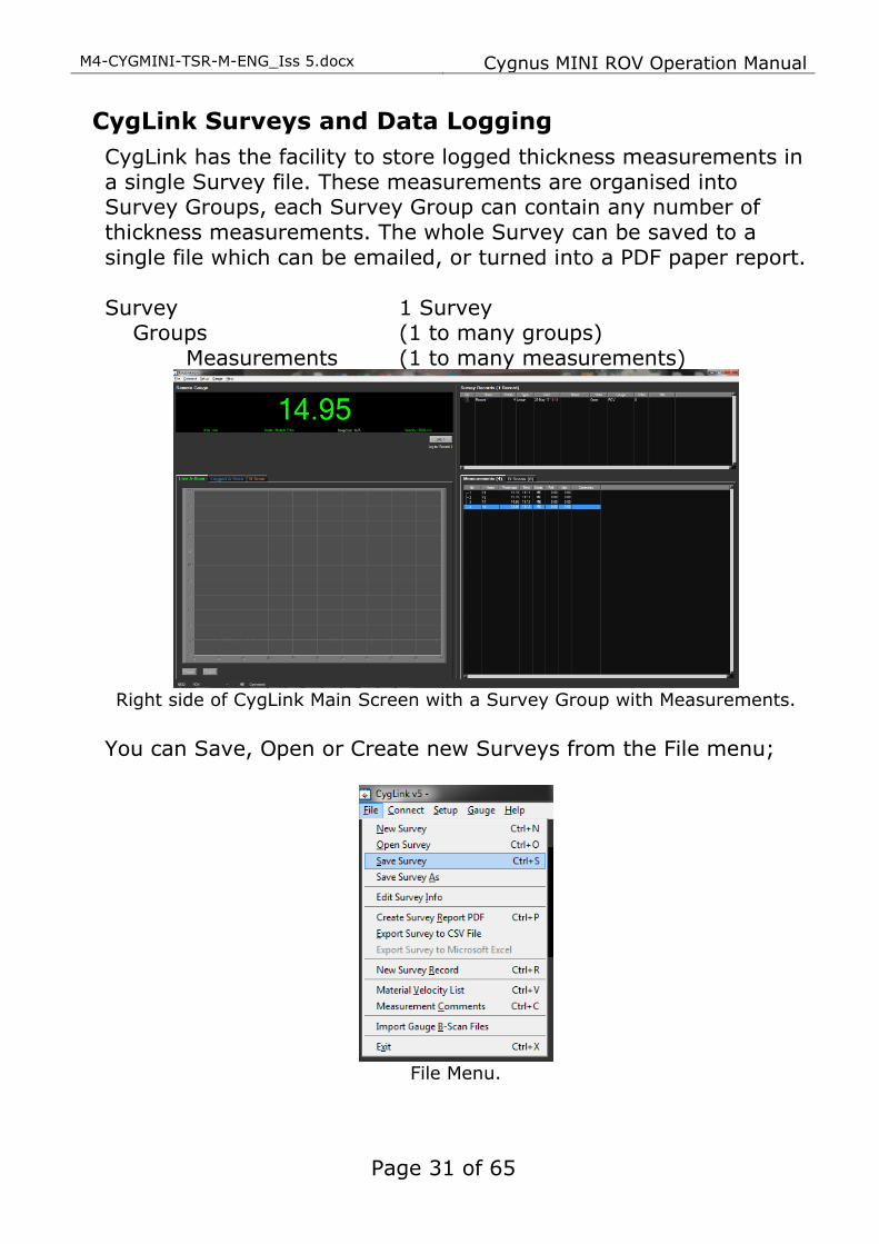
CygLink Surveys and Data Logging
CygLink has the facility to store logged thickness measurements in a single Survey file. These measurements are organised into Survey Groups, each Survey Group can contain any number of thickness measurements. The whole Survey can be saved to a single file which can be emailed, or turned into a PDF paper report. Survey 1 Survey
Groups (1 to many groups) Measurements (1 to many measurements)
Right side of CygLink Main Screen with a Survey Group with Measurements.
You can Save, Open or Create new Surveys from the File menu;
File Menu.

Cygnus MINI ROV Operation Manual M4-CYGMINI-TSR-M-ENG_Iss 5.docx
Page 32 of 65
Editing the Survey Details
The Survey contains all the Groups and is used to save all the data. You can also add details to the Survey that will be printed at the beginning of the PDF report. To create or edit the Survey details click File -> Edit Survey Details.
Survey Details Screen.
Editing the Survey Group Details
To view and edit the survey Group details right click the Survey Group and select properties.
To create a new survey record click File and select New Survey Record. Here you can set and related information such as a Reference Thickness and Minimum Thickness.

M4-CYGMINI-TSR-M-ENG_Iss 5.docx Cygnus MINI ROV Operation Manual
Page 33 of 65
Reference and Minimum Thickness Criteria
You can set a Reference Thickness and Minimum Thickness for each survey Group in the Survey Group Details screen. This will be applied to all measurements in the Group. The Reference Thickness is the thickness of metal when new. The Minimum Thickness is the minimum thickness – any measurement below this will be highlighted Red on the screen and in the survey report.
Producing a Survey Report Document
A PDF report can be produced containing all the Groups and thickness measurements in the Survey, grouped by each Survey Group. From the File menu select Create Survey Report PDF. You will be prompted for a filename first for the report first. Once the export process is complete, your report will automatically be displayed in your installed PDF viewer. The export may take a few seconds, depending on the number of logged measurements.
Logging Measurements Directly in CygLink
You can use CygLink to log the displayed topside thickness measurements into a Survey so they can be presented in the Survey report. To do this click the Log button below the thickness measurement.
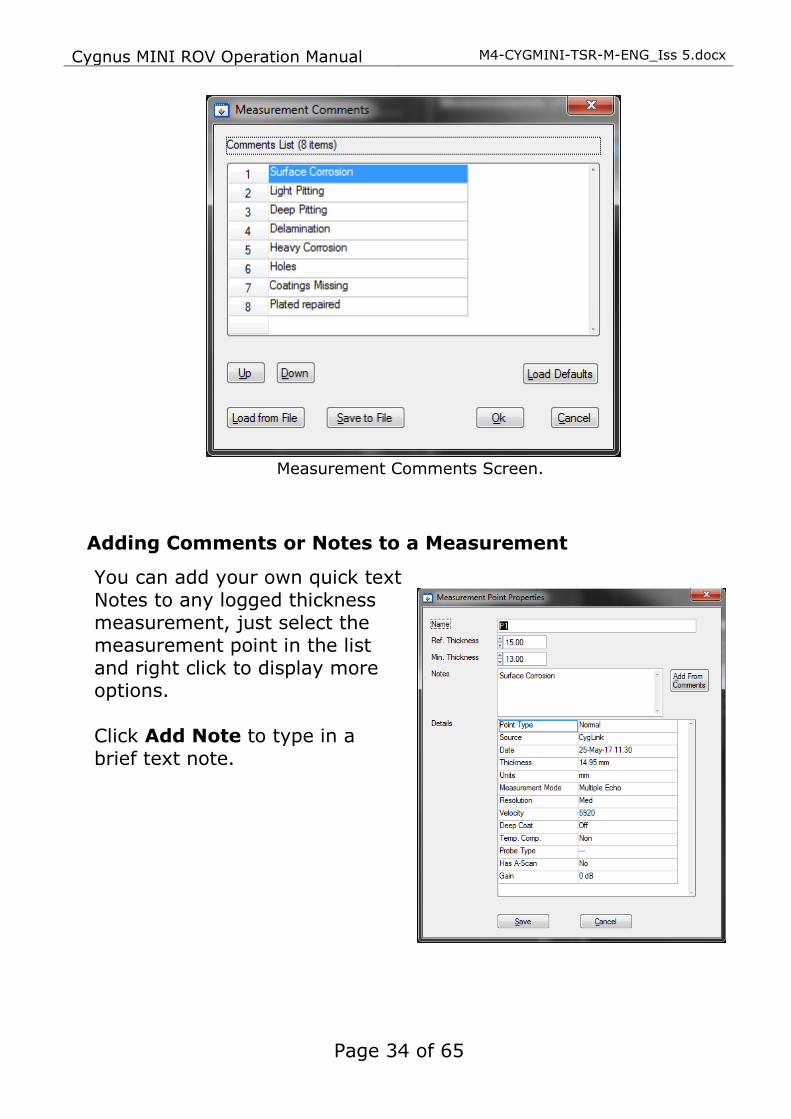
Pre-Set Measurement Comments List
You can add up to 8 short text comments that can then be used to append to a thickness measurement. To setup your comments
click File -> Measurement Comments.
Cygnus MINI ROV Operation Manual M4-CYGMINI-TSR-M-ENG_Iss 5.docx
Page 34 of 65
Measurement Comments Screen.
Adding Comments or Notes to a Measurement
You can add your own quick text
Notes to any logged thickness measurement, just select the measurement point in the list and right click to display more options. Click Add Note to type in a brief text note.
M4-CYGMINI-TSR-M-ENG_Iss 5.docx Cygnus MINI ROV Operation Manual
Page 35 of 65
CygLink Trouble Shooting
Connection Problems – USB Drivers
If you are unable to get a connection the first thing to try is updating the USB drivers for the Serial to USB converter. Windows is constantly being updated and as a result drivers also need to be updated to keep track of changes. The Serial to USB converter used for the ROV gauge is manufactured by KK Systems and uses Prolific drivers. You can search the web for the latest drivers from Prolific;
Type this into Google search “KK SYSTEMS USB232” Or follow this link directly to the KK Systems website; http://www.kksystems.com/english/html_files/software.htm Follow the instructions for USB232 Windows Drivers;
Wiring Problems
Sometimes the cable between the ROV gauge and the USB
converter is damaged, or has been repaired incorrectly. Although there are only 2 data wires they must be connected the correct way around. Double check the connections from the gauge’s connector to the serial converter connection. If you have the short serial to USB interface cable – check the gauge can connect to CygLink using this cable – if it works then the USB driver must be ok, the problem may lie in the long umbilical cable.
Cygnus MINI ROV Operation Manual M4-CYGMINI-TSR-M-ENG_Iss 5.docx
Page 36 of 65
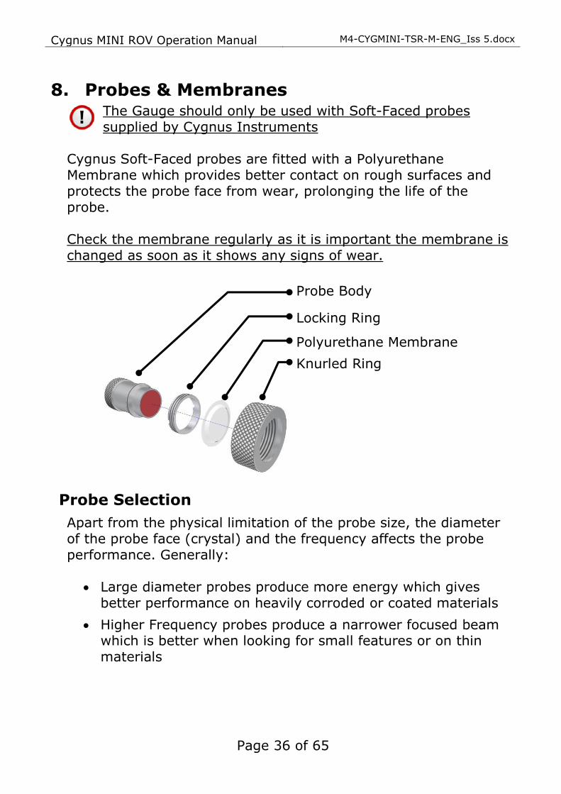
8. Probes & Membranes The Gauge should only be used with Soft-Faced probes supplied by Cygnus Instruments
Cygnus Soft-Faced probes are fitted with a Polyurethane Membrane which provides better contact on rough surfaces and protects the probe face from wear, prolonging the life of the probe. Check the membrane regularly as it is important the membrane is
changed as soon as it shows any signs of wear.
Probe Selection
Apart from the physical limitation of the probe size, the diameter of the probe face (crystal) and the frequency affects the probe performance. Generally:
• Large diameter probes produce more energy which gives better performance on heavily corroded or coated materials
• Higher Frequency probes produce a narrower focused beam which is better when looking for small features or on thin materials
Probe Body
Locking Ring
Polyurethane Membrane
Knurled Ring

M4-CYGMINI-TSR-M-ENG_Iss 5.docx Cygnus MINI ROV Operation Manual
Page 37 of 65
Changing the Membrane
1. Unscrew the Knurled Ring from the end of the Probe
2. Use the Locking Ring Key to unscrew the Locking Ring from inside the Knurled Ring. The old membrane can then be removed and discarded
3. Place a new membrane into the end of the Knurled Ring ensuring it locates in the groove
4. Screw the Locking Ring back inside the Knurled Ring and tighten with the Locking Ring Key
5. Place a few drops of Membrane Couplant on to the probe face
6. Screw the Knurled Ring back onto the probe. Use your thumb to squeeze the couplant from under the membrane as you
tighten the Knurled Ring down
7. You should see the membrane has a very thin film of couplant between itself and the probe face with no air bubbles

Cygnus MINI ROV Operation Manual M4-CYGMINI-TSR-M-ENG_Iss 5.docx
Page 38 of 65
Probe Selection & Specifications
Crystal
Diameter
Frequency Measurement
Range
Application
13 mm ½ inch
2¼ MHz
3.0 – 250 mm1 0.12 – 10 inch
This is the standard probe – suitable for most
applications
13 mm ½ inch
3½ MHz
2.0 – 150 mm 0.08 – 6 inch
Suitable for measurement on thinner sections where
surfaces are relatively rough
6 mm
¼ inch
5 MHz
1.0 – 50 mm
0.04 – 2 inch
The higher frequency and
narrower beam makes this probe ideal for measuring
small-bore tubing, thin section plate and other areas where
access is limited
13 mm
½ inch
5 MHz
1.0 – 50 mm
0.04 – 2 inch
Ideal for thin sections without
heavy corrosion
Lower frequency probes offer better penetration on heavy corrosion or coatings.
Probe Frequency Identification
The frequency of Cygnus probes is indicated by colour;
Red = 2.25 MHz Orange = 3.5 MHz Black = 5.0 MHz
ROV Probes
Coloured Probe Face
1 To measure thicknesses on tall thin cylinders or columns the height-width ratio should be no
less than 1.0:0.6 (Height: Width) otherwise side reflections prevent measurement.

M4-CYGMINI-TSR-M-ENG_Iss 5.docx Cygnus MINI ROV Operation Manual
Page 39 of 65
Mounting the Ultrasonic Probe
The Ultrasonic Probe is responsible for generating then transmitting and receiving the ultrasonic signal through the material being measured. To ensure the ultrasonic probe has the best chance of detecting the return echoes there are some basic rules that need to be considered when designing the probe holding tooling:
1. The probe face must be presented
flat/perpendicular to the surface being measured
2. Apply gentle pressure to the probe while measuring to maintain contact with the surface

Cygnus MINI ROV Operation Manual M4-CYGMINI-TSR-M-ENG_Iss 5.docx
Page 40 of 65
9. O-Ring Seals
Correct fitting of O-ring seals
There is one O-ring seal (‘A’) fitted to the nosecone and one O-ring seal (‘B’) fitted to the Gauge body.
Nosecone O-ring Location Gauge (Nosecone-End) O-ring
Location
Cover both O-Rings with a light coating of Silicone grease, then fit as shown in the diagram above, where:
• ‘A’ is fitted into the O-Ring groove in the nosecone housing
• ‘B’ is to be fitted in the O-Ring groove at the front of the instrument
It is important to ensure that the O-Rings are properly located. There is no need to stretch or force the O-Rings into their
locations. All parts are designed to ensure a good water-tight fit: Incorrect fitting will result in the instrument leaking.
• Be careful not to fit the ‘A’ O-ring in the wrong position, this is a common mistake that will cause incorrect gauge operation
B A

M4-CYGMINI-TSR-M-ENG_Iss 5.docx Cygnus MINI ROV Operation Manual
Page 41 of 65
Incorrect Location of Nosecone ‘A’ O-ring
• Only use the Torque Bar to undo the nosecone after each submersion.
Removing the Nosecone
The nosecone can be difficult to remove when the O-rings have been compressed so a Tommy Bar is supplied with the kit to allow extra leverage to be applied to ‘break’ the seal. Fit the Tommy Bar into the hole in the nosecone then unscrew using the Tommy Bar
as a lever.
Wrong
Torque or “Tommy”
Bar
Nosecone Gauge Body
Cygnus MINI ROV Operation Manual M4-CYGMINI-TSR-M-ENG_Iss 5.docx
Page 42 of 65
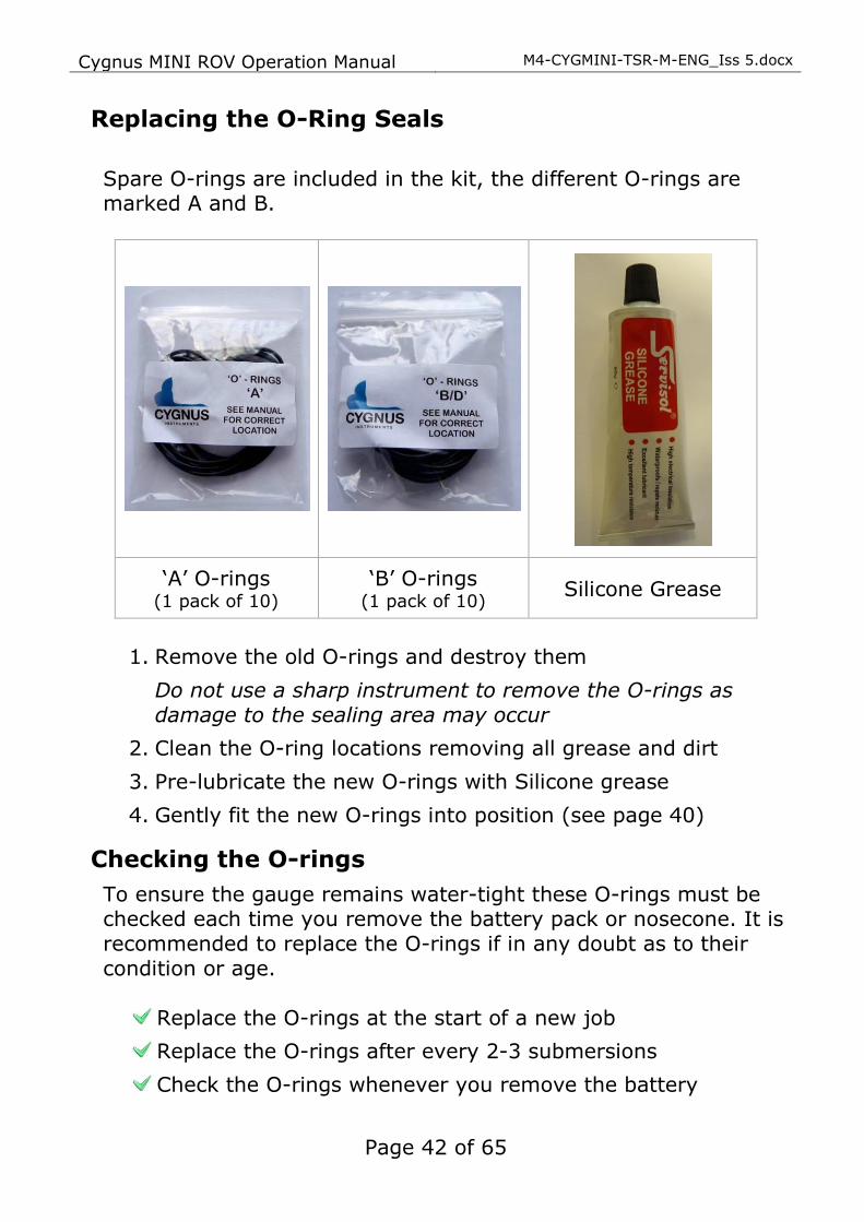
Replacing the O-Ring Seals
Spare O-rings are included in the kit, the different O-rings are marked A and B.
‘A’ O-rings (1 pack of 10)
‘B’ O-rings (1 pack of 10)
Silicone Grease
1. Remove the old O-rings and destroy them
Do not use a sharp instrument to remove the O-rings as damage to the sealing area may occur
2. Clean the O-ring locations removing all grease and dirt
3. Pre-lubricate the new O-rings with Silicone grease
4. Gently fit the new O-rings into position (see page 40)
Checking the O-rings
To ensure the gauge remains water-tight these O-rings must be checked each time you remove the battery pack or nosecone. It is recommended to replace the O-rings if in any doubt as to their condition or age.
Replace the O-rings at the start of a new job
Replace the O-rings after every 2-3 submersions
Check the O-rings whenever you remove the battery

M4-CYGMINI-TSR-M-ENG_Iss 5.docx Cygnus MINI ROV Operation Manual
Page 43 of 65
Check the O-rings whenever you remove the nosecone
Always lubricate the O-rings with Silicone grease
Do not use old or damaged O-rings
Never use the Gauge without any O-rings fitted
Spare O-rings are included in the Kit and can be ordered from Cygnus Instruments (see page 8 for contact details). Things to look for when inspecting the O-rings are:
• Any flats or signs of wear
• Any signs of pinching or trapping
• Any sand or dirt in the Silicone grease
• Any cuts or cracks

Cygnus MINI ROV Operation Manual M4-CYGMINI-TSR-M-ENG_Iss 5.docx
Page 44 of 65
10. General Points on Thickness Gauging On very rough surfaces and especially if both sides are badly corroded, it is often necessary to move the Probe around to locate a back wall reflector. Sometimes a slight rocking movement can help find reflectors which are otherwise impossible. Beware that in extreme conditions or if the plate is of poor quality and contains many inclusions the ultrasound will be scattered to such an extent that measurement may not be possible.
Beware that the multiple-echo technique will not work if the front and back surfaces of the material being measured are not close to parallel. Also note that long narrow bars cannot be gauged along their length with the multiple-echo method. The Gauge should not be used near arc-welding equipment, as this affects its performance.

M4-CYGMINI-TSR-M-ENG_Iss 5.docx Cygnus MINI ROV Operation Manual
Page 45 of 65
11. Troubleshooting
Difficulty obtaining a Reading
If there is 1 single flashing bar on the display – this means the Gauge is not receiving any echoes:
• Check that the Probe-lead is properly connected to both Probe and Gauge
• Check the condition of the lead and replace if necessary
If there is mostly 1 fixed bar plus 1 flashing bar this means that the Gauge is having difficulty obtaining more than one echo:
• Check the Probe and its membrane are properly assembled. If there are up to 3 fixed bars plus 1 flashing bar, but never any reading – this means the Gauge is receiving unrelated echoes from more than one reflector:
• On heavily corroded areas this is often a problem, try and
take measurements in adjacent areas of the same material
• Check the Gauge and Probe together on a test block, if there is still no reading the Gauge may require servicing
If Readings are Erratic or Unstable
• Check that the Probe-lead is properly connected to both Probe and Gauge
• Check that the Probe and its membrane are correctly assembled with sufficient couplant between the probe face and membrane
• Check the Probe-frequency is suitable for the probable minimum thickness of the material being measured. Probe frequencies which are too low cause doubling and tripling of the actual thickness

Cygnus MINI ROV Operation Manual M4-CYGMINI-TSR-M-ENG_Iss 5.docx
Page 46 of 65
12. The 3 Point Check The most frequent reasons found to cause difficulty getting readings are:
1. Is the Probe-membrane fitted correctly?
• Check that there is a thin layer of oil between the membrane and Probe-face, and with no air-bubbles trapped. See Changing the Membrane on Page 37
2. Is the Probe-lead OK?
• Check the probe lead is in good condition and is correctly attached to the Gauge. See page 12
3. Is the material measurable at all?
• Are the front and back faces of the material parallel? • Is the material too heavily corroded? • Is the material too thin for the Probe being used? (See page
38) It is often worth confirming that the Gauge is operating OK using a test sample, and also to confirm that the material can actually be measured by ultrasonic multiple-echo thickness measurement.

M4-CYGMINI-TSR-M-ENG_Iss 5.docx Cygnus MINI ROV Operation Manual
Page 47 of 65
13. Care and Servicing
Cleaning the Gauge
After each submersion, and while the instrument is still assembled, wash the unit in fresh water and allow to dry
To maintain the water-tight integrity of the assembly : the Gauge should be disassembled after every submersion, and the O-Rings should be replaced with new
Clean the O-Ring grooves, and ensure that there are no
particles remaining - a mild detergent may be necessary to remove grease from the O-Ring grooves
Care should be taken not to allow water into the instrument body whilst cleaning
Do not use solvents for cleaning
Do not use any abrasive cleaner
Use of O-Rings
When reassembling before a submersion: always replace both O-Rings with new, first ensuring that they are lubricated with Silicone grease
To avoid the risk of a leak: prevent accidental re-use by destroying all used O-Rings after each submersion
Data-link connector
Always apply a coating of Silicone grease to the pins of the data-link connector before insertion into the socket on the Gauge
If the Gauge is to be stored without the cable assembly connected, it is essential that the Blanking plug is inserted in the socket instead
The pins of the Blanking Plug should also be lubricated with Silicone grease

Cygnus MINI ROV Operation Manual M4-CYGMINI-TSR-M-ENG_Iss 5.docx
Page 48 of 65
Environmental
Do not subject the Gauge to temperatures greater than 60˚C (140˚F)
Do not store the Gauge and its kit for long periods in conditions of high humidity
Repairs
Apart from the fuse there are no user serviceable parts inside the Gauge. Therefore all repair work should be carried out by Cygnus Instruments or by an Authorised Cygnus Service
dealer
Returning the Gauge for Servicing
A full Manufacturer’s Factory Service is available from Cygnus Instruments.
The Complete Kit should always be returned for Service or Repair, including all Probes and Leads.
Cygnus Gauges are renowned for their reliability, very often
problems with getting measurements are simply due to the way the Gauge is being used. See Troubleshooting on Page 45. However, if you do need to return your Gauge for Repair please let us know the details of the problem, to help us guarantee the best possible service:
• Is the problem of an Intermittent Nature?
• Is there a problem turning the Gauge On? Or a problem with the Gauge turning itself off?
• Does the Gauge consistently give Incorrect or Unsteady Readings?
• Is it not possible to calibrate the Gauge?

M4-CYGMINI-TSR-M-ENG_Iss 5.docx Cygnus MINI ROV Operation Manual
Page 49 of 65
14. Information
Technical Specifications
General Attributes
Size Gauge Body dimensions, excluding cabling:
Length 160mm x Diameter 62mm (6.3 x 2.4 in.)
Probe Cable length: 1m (39.4 in.)
Weight In Air With Remote Probe 550 grams (19.4 ounce)
Power Supply External 7.5 to 30 V DC 150mA Supply
Operating Temperature Range -10°C to +50°C (14°F to 122°F)
Monitor Outputs N/A
Through Coating
Measurements.
Coatings up to 3 mm thick as standard.
Materials Sound Velocity from 1000 m/s to 9995 m/s
[0.0400 in/uS to 0.3998 in/uS]
Measurement Range Measurement Ranges in Steel:
2¼ MHz probe 3 mm to 250 mm [0.120 in. to 10.00 in.]
3½ MHz probe 2 mm to 150 mm [0.080 in. to 6.000 in.]
Accuracy ±0.05 mm (±0.002”)
High Resolution Mode and
measurement <100.0 mm
±0.1 mm (±0.005”)
Low Resolution Mode or
measurement >99.95 mm
Resolution 0.05 mm (0.002”) High Resolution Mode and
measurement <100.0 mm
0.1 mm (0.005”) Selectable. Low Resolution Mode or
measurement >99.95 mm
Display
Type of Display Remote Display Unit
Display Size N/A
Other Information
Data Output. RS-422 serial data output, 2400 Baud
Calibration setting storage. Calibration performed at Remote Display Unit
Calibration Mechanisms. N/A (Multiple Echo Gauge)
Environmental Rating. IP68 Rated to 500m (1640 ft) continuous immersion in sea
water
Compliance. RoHS Compliant.
Designed for BS EN 15317

Cygnus MINI ROV Operation Manual M4-CYGMINI-TSR-M-ENG_Iss 5.docx
Page 50 of 65
15. Serial Data Format The CygLink program and TSR are provided to automatically decode the measurement data sent from the Gauge, and to provide a calibrated display of the results. For users who want to display and log the data using their own software such as StarFix®, this section describes the arrangement of the data sent from the Gauge. Note the Cygnus MINI ROV Gauge has a fixed Velocity of Sound value of 6400 m/s, you must re-scale the received thickness value
for the velocity of sound required. For example when measuring carbon steel with a velocity of 5920 m/s you will need to apply the following conversion factor:
True Thickness = Received Thickness * 5920/6400
Protocol
1. Unidirectional - Gauge transmits only 2. Eight Data bits, 1 Start bit, 1 Stop bit, No Parity; 2400
baud 3. Four packets per second 4. Valid-Reading packet-length : 7 bytes 5. No-Reading packet-length : 3 bytes
Valid Thickness Measurement Packet Arrangement
Byte 1 2 3 4 5 6 7
Name SOH Status Data1 Data2 Data3 Data4 ETB
Type 1h ASCII ASCII ASCII ASCII 17h
No Thickness Measurement Packet Arrangement
Byte 1 2 3
Name SOH Status ETB
Type 1h 17h

M4-CYGMINI-TSR-M-ENG_Iss 5.docx Cygnus MINI ROV Operation Manual
Page 51 of 65
Status-byte Structure
Bit Name Details
7 Gauge Type =1 (always)
6 Resolution 1 = High Resolution 0 = Low resolution
5 Units 0 = Metric mm 1 = Imperial Inch
4 Reading Range 1 = High Range 0 = Low Range
3, 2 Echo Count Number of echoes found (0..3)
1 Calibration 1 = Remote (always)
0 No-Reading 1 = No Thickness Reading 0 = Valid Thickness Reading
Data-bytes Arrangement
The four data bytes are ASCII-encoded, decimal thickness value. Data byte 0 is most-significant. Leading-zeroes are replaced by ASCII Space [hex 20]. Decimal points are implied from the Status-byte – Units, Resolution and Range bits:
Reading-type Hi-Range Lo-Range
Imperial, Lo-Resolution x x . x x x . x x x
Metric, Lo-Resolution x x x . x x x x . x
Imperial, Hi-Resolution x x . x x x . x x x
Metric, Hi-Resolution x x x . x x x . x x

Cygnus MINI ROV Operation Manual M4-CYGMINI-TSR-M-ENG_Iss 5.docx
Page 52 of 65
Interpreting the Readings sent from the Gauge
Decimal Point position
Decimal Point position is implied from the combination of Range, Resolution, and Units bits in the Status byte of each Reading [see table above]
Range
The Gauge returns all Readings in a 4-byte decimal string Readings which require 5-bytes [e.g. 100.00+mm, or 10.000+inch] are auto-ranged to the 4 most significant bytes Range bit for every Reading must be read from the
Status-byte
Resolution
The Gauge is factory set to Lo-Resolution setting: 0.1 mm, or 0.005 inch but may be changed by the user to Hi-Resolution setting : 0.05 mm, or 0.002 inch as required
Units
The Gauge has a default Metric Units-setting. The Units bit must be read from the Status-byte

M4-CYGMINI-TSR-M-ENG_Iss 5.docx Cygnus MINI ROV Operation Manual
Page 53 of 65
16. Table of Sound Velocities Velocities will vary according to the precise grade and processing conditions of the material being measured.
This table is included as a guide only. Wherever possible, the Gauge should always be calibrated on the material under test.
These Velocities are given in good faith and are believed to be accurate within the limits described above.
No liability is accepted for errors. Velocities given are the compression wave velocity cl.
Material Velocity of Sound (V)
Conversion Factor (f)
m/s in/us
Aluminium (alloyed) 6380 0.2512 1.078
Aluminium (2014) 6320 0.2488 1.068
Aluminium (2024 T4) 6370 0.2508 1.076
Aluminium (2117 T4) 6500 0.2559 1.098
Brass (CuZn40) 4400 0.1732 0.743
Brass (Naval) 4330 0.1705 0.731
Brass (CuZn30) 4700 0.1850 0.794
Copper 4700 - 5000 0.1850 – 0.1969 0.794 – 0.845
Grey Cast Iron 4600 0.1811 0.777
Inconel 5700 0.2244 0.963
Lead 2150 0.0846 0.363
Monel 5400 0.2126 0.912
Nickel 5630 0.2217 0.951
Phosphor Bronze 3530 0.1390 0.596
Mild Steel 5920 0.2331 1.000
Tool Steel 5870 0.2311 0.992
Stainless Steel 302 5660 0.2228 0.956
Stainless Steel 347 5790 0.2279 0.978
Stainless Steel 314 5715 0.2250 0.965
Stainless Steel 316 5750 0.2264 0.971

Cygnus MINI ROV Operation Manual M4-CYGMINI-TSR-M-ENG_Iss 5.docx
Page 54 of 65
Material Velocity of Sound (V)
Conversion
Factor (f) m/s in/us
F51 Duplex Steel
UNS S31803 5715 - 5750 0.225 – 0.2264
0.956 –
0.971
Core Ten Steel EN12223 S355-J0
5920 0.2331 1.00
Tin 3320 0.1307 0.561
Titanium 6100 - 6230 0.2402 – 0.2453 1.030 – 1.052
Tungsten Carbide 6660 0.2622 1.125
Epoxy Resin 2500 0.0986 0.422
Acrylic 2730 0.1076 0.461
Nylon (Polyamide) 2620 0.1032 0.443
Reading Conversions
If only a few measurements are to be taken on a material other than Steel, it may be easier to leave the calibration set for Steel and merely convert the readings by multiplying by the Conversion Factor for the material being measured. This method avoids unnecessary recalibration.
Example: The Gauge is calibrated for Steel [5920 m/s], but the reading is being taken on Copper [4700 m/s] :
T = t x VCOPPER / VSTEEL = t x 4700 / 5920
= t x 0.794 thus: T = t x f [ where: f = VCOPPER / VSTEEL ] where : T = true thickness of Copper being measured
t = actual reading obtained f = Conversion Factor (from table) VCOPPER = Sound Velocity in Copper : 4700 m/s VSTEEL = Sound Velocity in Steel : 5920 m/s The Conversion Factor f: is given for various materials in the Table of Sound Velocities

M4-CYGMINI-TSR-M-ENG_Iss 5.docx Cygnus MINI ROV Operation Manual
Page 55 of 65
17. Part Number & Accessories List
Gauges
Part No. Description
001-7144/4 MINI ROV 500m ROV UTG Kit with 2.25MHz 13mm Probe
001-9944/4 MINI ROV 500m UTG Kit, without Probe
Surface/Topside Display
Part No. Description
001-7153/4 TOPSIDE REPEATER Kit with Video On Screen Display for Cygnus MINI ROV
Software
Part No. Description
001-8212 Cygnus CygLink v4 Topside Software on USB Flash Drive
Underwater Probes with 1 Metre Lead
All probes are fully assembled and include a spare membrane pack and knurled ring locking key.
Part No. Description
001-8334 Probe 2.25MHz 13mm for MINI ROV (1m cable)
003-9410 Probe 2.25MHz 19mm for Cygnus MINI ROV
Lower frequency probes offer better penetration on heavy corrosion/coatings. Please refer to page 38 for correct probe selection.

Cygnus MINI ROV Operation Manual M4-CYGMINI-TSR-M-ENG_Iss 5.docx
Page 56 of 65
Probe Spares and Membranes
Polyurethane Membranes are for normal use on surface
temperatures up to 75°C. Teflon Membranes are for use on surface temperatures up to 150°C
Part No. Description
001-3702 Pack of 20 Polyurethane Membranes for 6mm (¼”) Probes
001-3701 Pack of 20 Polyurethane Membranes for 13mm (½”) Probes
001-3700 Pack of 20 Polyurethane Membranes for 19mm
(¾”) Probes
001-4873 Pack of 10 Teflon Membranes for 6mm (¼”) Probes
001-4874 Pack of 10 Teflon Membranes for 13mm (½”) Probes
001-4875 Pack of 10 Teflon Membranes for 19mm (¾”) Probes

M4-CYGMINI-TSR-M-ENG_Iss 5.docx Cygnus MINI ROV Operation Manual
Page 57 of 65
Part No. Description
001-3706 Membrane Couplant (25ml)
001-3708 UCA-2M Ultrasonic Couplant Gel (100ml)
Knurled Rings
Part No. Description
001-3703 Knurled Ring Assembly for 6mm (¼”) Probes
001-3709 Knurled Ring Assembly for 13mm (½”) INOX Probes
001-3704 Knurled Ring Assembly for 13mm (½”) Probes
001-3705 Knurled Ring Assembly for 19mm (¾”) Probes
001-2612 Membrane Key for 6mm (¼”) Probes
001-2611 Membrane Key for 13mm (½”) Probes
001-2610 Membrane Key for 19mm (¾”) Probes
Cables and Leads
Part No. Description
001-0418 Impulse Connector 4-Way with Flying Lead
001-0432 Test Cable Impulse with DC Power for Mk3/4 ROV Gauges
Electronic Bodies Only
Part No. Description
001-7190/4 Cygnus MINI ROV Mountable UTG Gauge Body
001-7181/4 Cygnus Topside Repeater (Instrument Body)
Miscellaneous Spares
Part No. Description
001-4850 Steel Test Block 15 mm
001-4851 Steel Test Block 1/2"

Cygnus MINI ROV Operation Manual M4-CYGMINI-TSR-M-ENG_Iss 5.docx
Page 58 of 65
Part No. Description
01-4856 Carbon Steel Step Block 5-25mm in 5mm steps set in Perspex supplied with material type and dimensional accuracy traceable certificate.
001-8308 Isolated Data Converter RS422 to RS232 Model ‘K3’
003-0422 RS232 to USB Serial interface cable
001-3712 ‘O’ Ring Pack for Cygnus MINI ROV Mountable Gauge Kit contents: 20 x ‘O’-ring type A and 20 x ‘O’ Ring type B
001-4813-ROV Pelican Carry Case for Cygnus MINI ROV Gauge Kit

M4-CYGMINI-TSR-M-ENG_Iss 5.docx Cygnus MINI ROV Operation Manual
Page 59 of 65
18. Recycling and Disposal (EC Countries) The WEEE Directive (Waste Electrical and Electronic Equipment 2002/96.EC) has been put into place to ensure that products are recycled using best available treatment, recovery and recycling techniques to ensure human health and high environmental protection. The Gauge has been designed and manufactured with high quality materials and components which can be recycled and reused. It may contain hazardous substances that could impact health and
the environment. In order to avoid the dissemination of those substances in our environment and to diminish the pressure on natural resources we encourage you to dispose of this product correctly.
DO NOT dispose of this product with general household waste. DO dispose of the complete product including cables,
plugs and accessories in the designed WEEE collection facilities.
This product may also be returned to the agent or manufacturer who supplied it for safe end-of-life disposal.

Cygnus MINI ROV Operation Manual M4-CYGMINI-TSR-M-ENG_Iss 5.docx
Page 60 of 65
19. Warranty Information
LIMITED THREE YEAR WARRANTY
FOR CYGNUS ULTRASONIC THICKNESS GAUGES 1. Cygnus Instruments Limited (“CYGNUS”) warrants that, subject as set out below,
the Products manufactured by it (excluding consumables, batteries, probes, leads, microphones and telescopic extensions) will be free from defects in materials and
workmanship for a period of three years from the date of purchase either from CYGNUS or from an Authorised CYGNUS Distributor. Batteries, probes, leads, microphones and telescopic extensions are warranted for 6 months. This warranty is
limited to the original Purchaser of the Product and is not transferable. During the warranty period, CYGNUS will repair, replace or refund, at its option, any defective Products at no additional charge, provided that the product is returned by the
original Purchaser, shipping prepaid, to CYGNUS or an Authorised CYGNUS Distributor. If shipped by mail or any common carrier, the Purchaser must insure and accept all liability for loss or damage to the Product and must use shipping
containers equivalent to the original packaging. Replacement products or parts will be furnished on an exchange basis only. All replaced products or parts become the property of CYGNUS.
2. Any defects in materials or workmanship must be notified to CYGNUS by the
Purchaser within seven days after the discovery of the defect or failure.
3. Dated proof of purchase must be provided by the Purchaser when requesting
warranty work to be performed or making any other claim under this warranty.
CYGNUS will not be liable under this warranty unless the total price for the Product was paid by the due date for payment.
4. This warranty does not extend to any products which have been damaged as a result of, accident, misuse or abuse, natural or personal disaster, service, modification or repair by anyone other than CYGNUS or an Authorised CYGNUS
Service Centre, failure to properly store or maintain the Product, negligence, abnormal working conditions, fair wear and tear, or failure to follow the instructions issued by CYGNUS in relation to the Product.
5. Except as expressly set forth above or in the CYGNUS Terms of Sale, subject to
which the Products were purchased, all warranties, conditions or other terms implied
by Statute or Common Law are extended to the fullest extent permitted by law. 6. Except in respect of death or personal injury caused by the negligence of Cygnus,
Cygnus shall not be liable to the Purchaser or to any other person by reason of any representation (unless fraudulent), or any implied warranty, condition or other term, or any duty at common law, or under the express terms of the contract for purchase
of the Products, for loss of profit or for any indirect, special or consequential loss or damage, costs, expenses or other claims for compensation whatsoever (whether
caused by the negligence of Cygnus, its employees or agents or otherwise) which arise out of or in connection with the supply of the Products or their use or resale by the Purchaser or by any other person. The entire liability of Cygnus under or in
connection with the Products shall not exceed the price paid for the Products, except as expressly provided in this warranty.

M4-CYGMINI-TSR-M-ENG_Iss 5.docx Cygnus MINI ROV Operation Manual
Page 61 of 65
20. Pressure Test Statement
All MINI ROV gauges are pressure tested in water as part of our test procedures. Please refer to the environmental rating section for further information.

Cygnus MINI ROV Operation Manual M4-CYGMINI-TSR-M-ENG_Iss 5.docx
Page 62 of 65
K3
ISO
LA
TE
D I
NT
ER
FA
CE
CO
NV
ER
TE
R
RS
23
2
RS
23
2/R
S4
85
WW
W.K
KS
YS
TE
MS
.CO
M
RS
23
2
RS
42
2/R
S4
85
SY
ST
EM
SK
21. Independent Cable Connection
Recommended cable connection for direct cabling
from Cygnus MINI ROV Gauge to surface computer
Cable-termination: for long cables it may help to fit a 120 Ω
resistor, in series with a 1nF capacitor, between the TX+ and TX- connections inside the 9-way D-type plug. See datasheets on the supplied USB Flash Drive for the K3 receiver, and MAX483 line driver.

M4-CYGMINI-TSR-M-ENG_Iss 5.docx Cygnus MINI ROV Operation Manual
Page 63 of 65
22. ROV-Local Termination Connection
Recommended cable connection from Cygnus MINI
ROV Gauge to ROV craft
Cygnus MINI ROV Operation Manual M4-CYGMINI-TSR-M-ENG_Iss 5.docx
Page 64 of 65
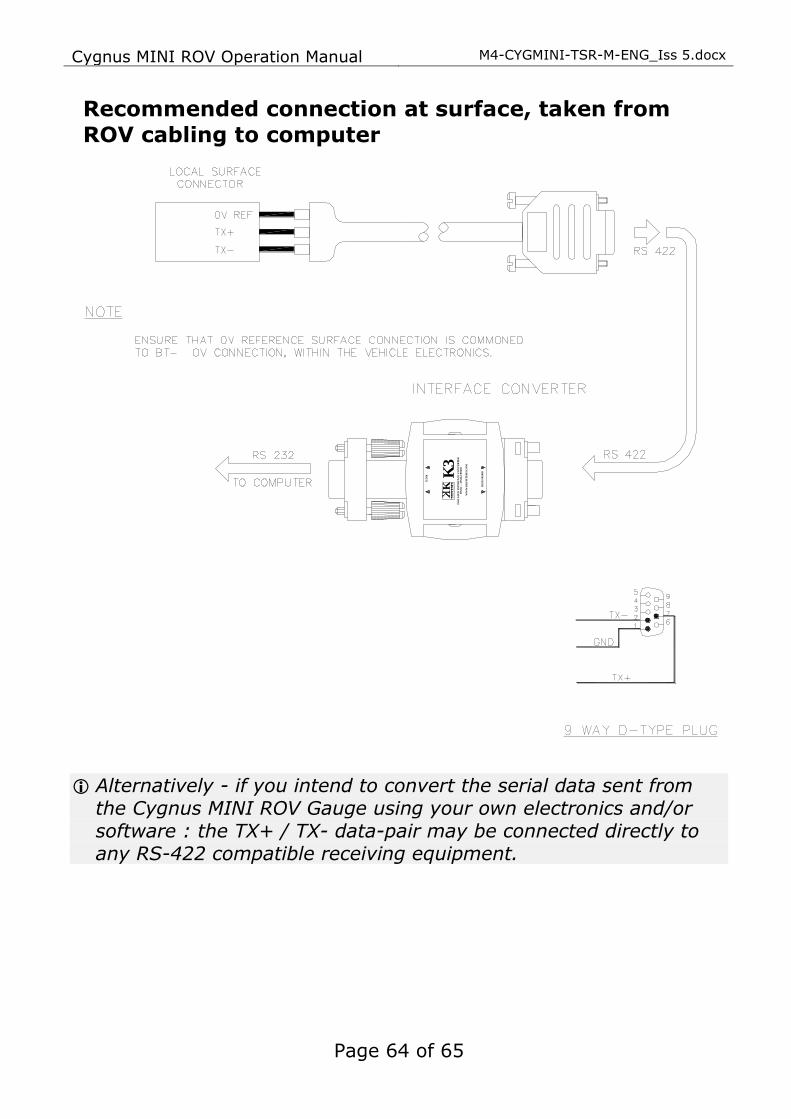
Recommended connection at surface, taken from
ROV cabling to computer
Alternatively - if you intend to convert the serial data sent from
the Cygnus MINI ROV Gauge using your own electronics and/or
software : the TX+ / TX- data-pair may be connected directly to any RS-422 compatible receiving equipment.
K3
KS
YS
TE
MS
RS
23
2
RS
42
2/R
S4
85
WW
W.K
KS
YS
TE
MS
.CO
M
RS
23
2/R
S4
85
RS
23
2
ISO
LA
TE
D I
NT
ER
FA
CE
CO
NV
ER
TE
R

M4-CYGMINI-TSR-M-ENG_Iss 5.docx Cygnus MINI ROV Operation Manual
Page 65 of 65
23. Index Accessories
Cables and Leads, 57 Electronic Bodies, 57 Knurled Rings, 57 Membrane Couplant, 57 Miscellaneous Spares, 57 Probe spares and
mambranes, 56 Software, 55
Calibration Conversion Factor, 54 Known Thickness, 18
Cleaning, 47 CygLink
COM Port, 25 Comment List, 33 Comments, 34 Connection to Gauge, 28 Gauge Settings, 29
Installation, 24 Logging, 33 Material Table, 29 PDF, 33
Data Output, 14 Disposal, 59 Measuring Through Water, 16 Nosecone
Removing, 41 O-Rings
Checking, 42
Molykote, 42 Replacing, 41
Power Supply, 14 Probes
Knurled Ring, 37 Locking Ring Key, 37 Membrane Couplant, 37 Polyurethane Membrane
Membrane, 36 Selection, 36 Specifications, 38
Problems, 48 Pulse-echo, 7 Recycling, 59 Repair, 48 Rough surfaces, 44 Serial Data Format, 50 Service, 48 Sound Velocities, 53 Specifications, 53 Test block, 18
Tommy Bar, 41 Top Side Repeater, 19 Topside Repeater
Automatic Display Backlight, 20
Display Units, 19, 20, 30 HOLD, 20
Triple Echo Verification, 7 Troubleshooting, 45 Unrelated echoes, 45 Video Overlay, 20
Warranty, 60 WEEE Directive, 59