Seeding High Redshift QSOs by Collisional Runaway in Primordial Star Clusters

Instruction Manual Cyclone 40
40 Meter Transceiver
Revision 0 Copyright 2013
David Cripe NM0S &
Four State QRP Group

Introduction Thank you for purchasing a Cyclone 40 transceiver kit. We hope you will enjoy building it and have many QSOs with it to the 40-Meter band. This kit is comprised of high-quality components, a silkscreened, solder-masked, double-sided PC board, and pre-drilled, silkscreened enclosure Theory of Operation The Cyclone is 40M QRP CW transceiver, designed to maximize performance with a minimum of components, cost and assembly effort. To achieve this, a number of very unusual circuits have been employed. The heart of the Cyclone is the 4 MHz variable-frequency oscillator, made up of transistor Q6, inductor L5, capacitors C14 and C15, and resistor R5. This frequency of the oscillator is tuned by changing the inductance of L5, which is done by moving a brass screw inside the center of L5. The conductivity of this screw essentially blocks the inductor's magnetic field, effectively changing the area inside the inductor, reducing its inductance. Such a circuit is called a Permittivity-Tuned-Oscillator, or PTO. The frequency range of this oscillator is nominally 3.85 to 4.00 MHz. A second oscillator operates at a fixed frequency of 11.00 MHz. This is the Local Oscillator, comprised of crystal X5, resistors R4, R13, capacitors C16 and C17, and transistor Q11. The output of this oscillator is mixed against the IF signal to demodulate the received audio, and also mixed with the PTO frequency to generate the transmit frequency of the radio. The IC U2, a 74HC240 performs many functions within the transceiver. This device contains eight inverting logic gates, in two banks of four. These gates are controllable into a 'Tri-State' output, where the output voltage is neither high nor low, but instead a high impedance. One bank of four gates is used for transmit functions (U2, pins 2, 4, 6, 8, 12, 14, 16, and 18), while the second bank of four gates is used for receive functions (U2, pins 3, 5, 7, 11, 13, 15, and 17). These two banks are enabled by a logic-low input at pins 1 and 19, respectively. When in the transmit mode, the 4 MHz PTO and 11 MHz LO signals are mixed in Q8 to create the 7 MHz transmit frequency. This is filtered by T3 and T4, and amplified by U2-2 and -4. The output of U2-16 is fed to U2-6 there it is inverted. The outputs at U2-18 and -14, respectively, comprise a complimentary, push-pull signal at the transmit frequency, driving the gates of PA transistors Q3 and Q4.

The transmit power amplifier utilizes power amplifier transistors Q3 and Q4 in push-pull Class-E mode to generate 4W nominally from 12v, at 85% efficiency. When the transmitter is keyed, transistor Q7 is driven on, applying DC power to the PA drain choke L4, allowing Q3 and Q4 to make power. When in the receive mode, the PTO output is fed to U2, pins 15 and 17, buffering and amplifying the sine-wave oscillator signal to create a logic-level square wave signal. The output of U2-5 is fed to U2-13 to create a logically-inverted signal at U2-7. The signals at U2-3 and -7, respectively, comprise a complimentary, push-pull signal at the PTO frequency, driving the gates of PA transistors Q3 and Q4. The received signal is switched by these transistors, converting the 7 MHz received signals to 11 MHz for the IF filter. The IF filter, comprised of X1-X4, is a four-pole, 11 MHz crystal filter with a Gaussian shape, filtering the CW signal with minimal ringing. The filter is fed directly from the center tap of the PA output transformer, consequently, no transmit/receive switching of the antenna is required. The output of the IF filter is amplified by Q5, and fed to the active mixer circuit of Q1 and Q2. The 11 MHz LO signal is fed into the emitters of Q1 and Q2, mixing against the IF signal, producing demodulated audio at the primary of transformer T2. The secondary of transformer T2 feeds the audio signal into the emitter of Q10, the first audio amplifier. This feeds the first stage of U3, a TL072 op amp. This is configured as a high-gain bandpass filter, adding further selectivity to the audio signal. Audio peaks cause current conduction by Q9, the AGC detector. This charges C33, and provides current to base of Q12, the AGC attenuator. Transistor Q12 is operated as a variable attenuator, controlled by its base current. This audio-derived AGC loop is effective at attenuating and limiting large audio signals. The audio signal is then fed through the volume control potentiometer R6, to the second stage of U3, a unity-gain amplifier with an output buffered by complimentary audio amplifier transistors Q13 and Q14. These transistors feed the headphone though J2. The amplifier feeds the tip and ring connections of the headphone jack, placing both headphone elements of a stereo headset in series, reducing the current consumption of the amplifier. When the transmitter is keyed, the mute switch transistor Q15 is closed, and limits the passage of audio transients through the audio amplifier.

A PIC microcontroller U4 serves both as a frequency counter, as well as the sidetone oscillator. Pressing the FREQ counter at the side of the enclosure activates the counter, which counts the VFO frequency, and sends four digits of the count (excluding the megahertz digit) as CW characters to the headphone jack. The counter works both on transmit and receive. Coding for the counter was provided by Adrien Hill, KC0YOI.
First Steps Before getting started with building the receiver, take some time to organize and familiarize yourself with the parts provided and check them against the Bill of Material. Building over a cookie sheet is recommended to minimize parts being lost. If parts are missing in your kit, send an email to Terry Fletcher, WA0ITP at [email protected]. He will promptly provide replacements. Schematic files are provided as part of documentation package. It is highly recommended to print a couple of copies at 11 X 17 inch format at your local UPS Store, Staples, etc. As you build, use a highlighter to mark off parts that have been soldered onto the PCB on one copy. When you think you are done, you can check that copy to verify that all of the parts have been installed. Build section schematics are also provided for convenience that match up with the build steps with their parts call-outs. It is helpful to acquire the necessary tools and supplies before beginning. These include: *Soldering iron – Preferably thermostatically controlled. *Fine 60/40 rosin core solder *Wire strippers *X-Acto knife *Diagonal cutters *Needle-nose pliers *Phillips screwdriver *Non-metallic alignment tool *Electrical tape *Clear fingernail polish *Magnifier *Rubber Bands *Digital volt-ohm-meter Soldering is not hard if the proper procedure is followed. The soldering iron is to be used to heat up the PC pad and component lead, and the solder applied to

the pad, where it melts and flows into the hole. Do not melt the solder onto the tip of the iron and then attempt to dab it onto the joint – a defective connection will result! After soldering, check the top (component side) of the board, to be sure the solder has filed the hole completely, and wicked up around the component lead. Re-heat and apply more solder if necessary. The PC boards used for the circuit and for enclosure are contained in two panels, with the individual boards separated by V-groves. To begin assembling the kit, the boards must be separated. Placing a panel on a table or workbench so that the v-groove rests over the edge, the boards may be cleanly separated by pressing down firmly on each section. CAPACITORS The ceramic monolythic capacitors used throughout the kit are small and their markings not always easy to read. Use a magnifier to verify their values before installing. Electrolytic capacitors must be installed in the correct polarity. The cases are marked to indicate the negative terminal, which goes into the round pad on the board. Install the capacitors, solder and trim the leads. Check off each part as you install it. After C15, the dipped silver mica capacitor is installed, save the leads you trim off of it. Set them aside – you'll need them later!
√ Ref Value Marking Type
C14 0.0047 472 or 4N7 Plastic
C19 0.01 103 Ceramic Monolythic
C25 0.01 103 Ceramic Monolythic
C30 0.01 103 Ceramic Monolythic
C32 0.01 103 Ceramic Monolythic
C1 0.1 104 Ceramic Monolythic
C2 0.1 104 Ceramic Monolythic
C21 0.1 104 Ceramic Monolythic
C22 0.1 104 Ceramic Monolythic
C23 0.1 104 Ceramic Monolythic
C29 0.1 104 Ceramic Monolythic

C31 0.1 104 Ceramic Monolythic
C26 10 10u or 106 Aluminum Electrolytic
C33 10 10u or 106 Aluminum Electrolytic
C37 10 10u or 106 Aluminum Electrolytic
C28 100 100u or 107 Aluminum Electrolytic
C34 100 100u or 107 Aluminum Electrolytic
C35 100 100u or 107 Aluminum Electrolytic
C24 470 470u or 477 Aluminum Electrolytic
C6 1000p 102 or 1N0 Ceramic monolythic
C7 1000p 102 or 1N0 Ceramic monolythic
C8 120p 121 Ceramic monolythic
C11 120p 121 Ceramic monolythic
C10 180p 181 Ceramic monolythic
C5 220p 221 Ceramic monolythic
C13 270p 271 Ceramic monolythic
C12 300p 301 Ceramic monolythic
C15 330p 331 Dipped Silver Mica SAVE THE LEADS!
C9 470p 471 Ceramic monolythic
C36 470p 471 Ceramic monolythic
C18 56p 560 or 56j Ceramic monolythic
C27 680p 681 Ceramic monolythic
C20 68p 680 or 68j Ceramic monolythic
C3 82p 820 or 82j Ceramic monolythic
C4 82p 820 or 82j Ceramic monolythic
C16 82p 820 or 82j Ceramic monolythic
C17 82p 820 or 82j Ceramic monolythic

RESISTORS Next, install the resistors.
√ Ref Value Marking Description
R10 330 Orange-Orange-Brown 1/4W
R24 330 Orange-Orange-Brown 1/4W
R9 470 Yellow-Violet-Brown 1/4W
R3 680 Blue-Grey-Brown 1/4W
R4 1.0k Brown-Black-Red 1/4W
R7 1.0k Brown-Black-Red 1/4W
R8 1.0M Brown-Black-Green 1/4W
R13 1.0M Brown-Black-Green 1/4W
R20 1.0M Brown-Black-Green 1/4W
R21 1.0M Brown-Black-Green 1/4W
R23 1.0M Brown-Black-Green 1/4W
R26 1.0M Brown-Black-Green 1/4W
R2 1.5k Brown-Green-Red 1/4W
R1 100k Brown-Black-Yellow 1/4W
R11 100k, 10t 104 Blue Pot
R5 10k Brown-Black-Orange 1/4W
R15 10k Brown-Black-Orange 1/4W
R22 10k Brown-Black-Orange 1/4W
R6 10k - Volume Control
R16 10k, 10t 103 Blue pot
R12 18k Brown-Grey-Orange 1/4W
R17 3.3k Orange-Orange-Red 1/4W
R19 3.3k Orange-Orange-Red 1/4W
R25 3.3k Orange-Orange-Red 1/4W
R14 330k Orange-Orange-Yellow 1/4W
R18 470k Yellow-Violet-Yellow 1/4W
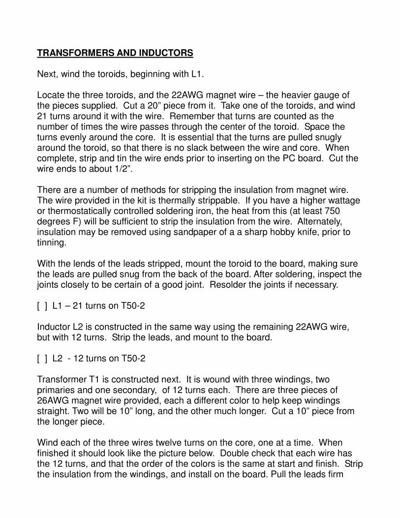
TRANSFORMERS AND INDUCTORS Next, wind the toroids, beginning with L1. Locate the three toroids, and the 22AWG magnet wire – the heavier gauge of the pieces supplied. Cut a 20” piece from it. Take one of the toroids, and wind 21 turns around it with the wire. Remember that turns are counted as the number of times the wire passes through the center of the toroid. Space the turns evenly around the core. It is essential that the turns are pulled snugly around the toroid, so that there is no slack between the wire and core. When complete, strip and tin the wire ends prior to inserting on the PC board. Cut the wire ends to about 1/2”. There are a number of methods for stripping the insulation from magnet wire. The wire provided in the kit is thermally strippable. If you have a higher wattage or thermostatically controlled soldering iron, the heat from this (at least 750 degrees F) will be sufficient to strip the insulation from the wire. Alternately, insulation may be removed using sandpaper of a a sharp hobby knife, prior to tinning. With the lends of the leads stripped, mount the toroid to the board, making sure the leads are pulled snug from the back of the board. After soldering, inspect the joints closely to be certain of a good joint. Resolder the joints if necessary. [ ] L1 – 21 turns on T50-2 Inductor L2 is constructed in the same way using the remaining 22AWG wire, but with 12 turns. Strip the leads, and mount to the board. [ ] L2 - 12 turns on T50-2 Transformer T1 is constructed next. It is wound with three windings, two primaries and one secondary, of 12 turns each. There are three pieces of 26AWG magnet wire provided, each a different color to help keep windings straight. Two will be 10” long, and the other much longer. Cut a 10” piece from the longer piece. Wind each of the three wires twelve turns on the core, one at a time. When finished it should look like the picture below. Double check that each wire has the 12 turns, and that the order of the colors is the same at start and finish. Strip the insulation from the windings, and install on the board. Pull the leads firm

from the rear of the board to assure the winds are snug on the toroid. [ ] T1 Toroidal Transformer
Figure 1: Winding of T1
Install the remaining transformers at this time. Transformer T2 is a blue audio transformer. Notice there is a letter 'P' printed on one side of T2, designating the primary terminals. Be certain that that this transformer is installed with the primary corresponding to the pads marked 'P' on the board. Bend the mounting tabs over to provide mechanical strength, and solder them too. [ ] T2 Audio Transformer Transformers T3 and T4 are shielded IF transformers. Locate and install these also. [ ] T3 - IF Transformer [ ] T4 - IF Transformer Locate and install L3, the 100uH molded choke. It will be marked '100uH'. [ ] L3 100uH Do not install L4 or L5 at this time.

CRYSTALS Install all five 11.000 MHz crystals, X1 through X5
[ ] X1 [ } X2 [ ] X3 [ ] X4 [ ] X5 SEMICONDUCTORS Locate the 8-pin DIP IC socket. Install it in the U4 position, making certain to align the polarity notch of the socket with the mark on the PC board, facing the left side of the board. [ ] 8-pin DIP socket U4 Identify and install the following components. Be certain that their polarity is correct, and that they match the board silkscreen symbols.
MODIFICATION NOTE 1: Purchasers of the original version boards (no revision notice marked on the PC board) must make the following modifications during installation of U1 and U4: Prior to installation, trim the legs of U4-5, U1-6 and U1-16 just short enough so they do not extend below the plastic body of the IC Solder a jumper connecting U1-6 to U1-16 over the top of the IC prior to installation. A resistor lead will work. Cut a 1 3/4” length of 26 AWG magnet wire, and strip the insulation 1/16” back from each end. Solder one end to U4-5 prior to its installation. Install U4 and solder the other end of this wire to TP-1.
√ Ref Value Description
D1 1N914 Glass diode
D2 SA15 Surge suppressor

U1 78M05 5v regulator, TO-220
U2 74HC240 Octal Inverter, DIP-20
U3 TL072 Dual OpAmp, DIP-8
U4 PIC12F609 Counter IC
Q1 2N3904 TO-92
Q2 2N3904 “
Q5 2N3904 “
Q10 2N3904 “
Q12 2N3904 “
Q13 2N3904 “
Q9 2N3906 “
Q14 2N3906 “
Q6 2N7000 “
Q15 2N7000 “
Q8 MPF102 “
Q11 MPF102 “
Q7 ZTX749 “
Q3 ZVN4206A “
Q4 ZVN4206A “
HARDWARE, SWITCHES AND CONNECTORS Take the T-nut and the front panel. The T-nut inserts through the front of the front panel. The front panel location for the T-nut has mounting holes for either the three-prong or four-prong versions of the T-nut. The mounting prongs of the T-nut may not exactly align with the holes in the board, so you may need to re-align them with your needle-nose pliers. Locate the brass screw provided in the kit. Notice one end has been cut, and one end is finished. Screw the finished end into the T-nut to verify that its threading is clean and smooth, then remove. Place the T-nut flat on your workbench, placing the enclosure front panel front-

side down over it, so the mounting prongs pass through the appropriate holes in the board. It may be a snug fit. Press the board down over the prongs until the board bottoms out on the T-nut. The prongs should be soldered at the back side of the board. You may need a higher wattage iron to heat the T-nut sufficiently to melt the solder. Do not attempt to solder the center pedestal of the T-nut. [ ] T-nut Solder SW2, the 'FREQ' pushbutton switch, to the board. Be certain it is flush to the board before soldering. [ ] SW2 FREQ pushbutton Solder J1 and J2, the Key and Headphone jacks to the board. These are 1/8” stereo connectors. Be certain that they are pressed flush to the board before soldering, and re-solder while pressing down if necessary to assure they are as close as possible too the board. [ ] J1 – 1/8” Stereo Jack – Key [ ] J2 – 1/8” Stereo Jack – Headphones Adjacent to the KEY jack are three pads connecting to the jack tip and ring, and to the transmitter keying line. This is to facilitate addition of an optional keyer circuit. If one is not to be used, jumper the TIP pad to the adjacent key pad at JP1 using a snipped-off component lead.
Install the J3, the BNC antenna jack. It will require some time to heat the ground pins in order to solder them. [ ] J3 – BNC Cut two, three-inch lengths of 22 gauge insulated, stranded wire. Strip 1/4” of insulation from both ends of each piece. Solder them on to the terminals of the coaxial power connector. The shell of the connector is the negative terminal, and the center pin is positive. Solder the other ends of the wires to the corresponding '+' and '-' pads at the left edge of the board. Verify that the shell of the connector is connected to the '-' pad, the ground plane of the board. The mating connector for this is a standard 2.5mm/5.5mm coaxial power connector, wired so that the center conductor is positive.

ENCLOSURE Take the finished circuit board, and, using the 3/8” screws inserted through the bottom of the board, install the 1.5" aluminum spacers on the top side. Invert the board, so that it rests on the spacers. Rest the front panel against the front edge of the circuit board. Be sure that the key and headphone jacks fit through the holes on the front panel, and the edge of the front panel rests evenly against the workbench surface. Assemble the four side panel pieces around the main board, and use rubber bands to temporarily hold them in place, making sure that the edges are perfectly flush. Be sure that the horizontal silver stripes on the side panels rest against the edge of the circuit board, and that the vertical slots are toward the rear of the unit. Using a soldering iron (30W to 40W would help supply sufficient heat) place a small, pea-sized, solder fillet at the upper corner of the juncture of each of the four side panels. Flip the assembly over so that it is right-side-up, and remove the aluminum spacers. Add small solder fillets on the upper corners of the four side panel junctures. Inspect to assure that each joint is flush and square, and re-adjust the solder joints if necessary. Re-invert the assembly, and attach the circuit board to the side panels using solder fillets about 1/2" inside from each corner. It is NOT recommended to solder the entire length of the joints. If it would be necessary to disassemble the enclosure at a future it would be nearly impossible to do so. PTO Locate the threaded nylon PTO coil form, the remaining 26 AWG magnet wire, the brass screw, and the two leads from C15. Using an indelible marker or hobby knife, mark the nylon coil form 1/8” (3.5 mm) from each end. Screw the brass screw entirely into the nylon spacer, finished end first.. Fix the nylon spacer horizontally into a bench vise, clamp, or 'third hand', so that the marks are at the top. Take the leads saved from C15. Straighten them as much as possible. Take one lead, and hold it vertically, near the top with your needle nose pliers. Position the bottom of the lead on one of the marks on the nylon spacer. Touch your soldering iron to the lead about 1/4” from the bottom of the lead to heat it. As the plastic of the spacer melts from the heat of the lead, firmly and quickly force the hot lead straight down into the plastic until you feel it bottom out on the screw inside. Immediately remove the iron, while holding the lead in position until the plastic cools and sets. Check with your ohm meter that there is NO continuity between the lead and the brass screw, while rotating the screw

through a complete turn. Repeat with the second lead. Leave the assembly in the clamp for the time being. Take the 22AWG magnet wire. Strip and tin 1/4” of one end. Bend the end in the middle of the tinned section into a sharp 'v'. Place this over one of the newly inserted leads, so that the end of the 'v' points away from the center of the coil form. Hold the wire about 1/16” (1.5 mm) from the surface of the plastic, and crimp in place with the needle nose pliers. Solder into place quickly, and promptly remove the iron before the lead loosens from the plastic spacer. Remove the spacer from the vise or clamp, and remove the screw from the center. Wrap the 26AWG magnet wire 22 turns around the spacer. Strip a ¼” section of the wire where it touches the second PTO lead. Pulling the wire snug around the spacer, bend the magnet wire where it touches the PTO lead, and solder it into place. Trim off the excess wire. Trim the length of the PTO leads extending from the spacer to 1” (25mm). Using needle nose pliers to support the lead at the body of the spacer, bend it into a ‘knee’ shape as per the illustration below. Insert the leads into the PTO position on the board (labeled L6), and solder into place. The PTO coil should be directly above its mounting pads.
Figure 2: Wound PTO Coil

Figure 3: PTO Coil with ‘knees’
Insert the screw through the front panel T-nut until it touches the end of the PTO coil form. Gently bend the PTO leads until the end of the screw lines up with the threaded hole in the PTO coil form. Continue screwing the brass screw into the PTO coil form until the end of the screw is approximately 1/8” from the end of coil form, directly even with the end of the coil winding. Next, we shim the screw so that it fits the tuning knob. Take a 4” strip of black electrical tape and wrap it around the exposed end of the PTO screw, flush with the T-nut. Cut off any tape that extends past the end of the screw. Test fit with the large knob to insure a reasonably close fit. Remove or add tape as necessary. Install the knob flush with the front panel. Install the small knob over the volume control shaft. With the switch in the OFF position, make sure the marker on the knob is aligned with the line on the front panel. Take time now to give the board a close visual inspection. Hold the board up to light to make certain that all holes have been soldered. Using a magnifier,

inspect all solder joints for quality, and touch-up any needing it. Inspect for solder blobs or other possible shorts. Double check that all polarized components have been installed properly. Install the bottom cover to the enclosure, using the 1/2” screws and 1/4” spacers at the bottom of the board, and the 1.5” threaded spacers at the top of the board. Locate a regulated 12v supply. Assemble a power cable using a 2.5x5.5mm coaxial power plug, center positive. Fuse the line with a 1A fast-blow fuse. Make up a cable for the key. Obtain an 1/8” audio plug, and wire your key to the tip and shell. The shell is grounded, and the connector tip is the keying line. ALIGNMENT With the Cyclone power switch OFF, plug a pair of headphones or ear buds into the headphone connector. Turn on the 12v supply, and the power switch of the Cyclone. Advance the volume control fully. You should hear a slight hiss of the audio amplifier circuitry. If you hear hiss in the headphones, and the power supply fuse has not blown, we may proceed with alignment. The first task is alignment of the PTO coil. It is necessary to set the PTO frequency at 4.000 MHz when the PTO screw is fully inserted. Press the FREQ button at the side of the enclosure. You should hear a sequence of four CW numerals played in the headphones. These four digits represent the count in hundreds of kilohertz, tens of kilohertz, kilohertz, and hundred hertz. This represents the transmit frequency, which is calculated in the counter IC by subtracting the PTO frequency from the 11 MHz LO frequency. If the PTO is aligned, the count should be 0 – 0 – 0 – 0. If the number begins with a 9, then the PTO frequency is too high, and the PTO turns should be spread. If the number is greater than zero, than the PTO frequency is too low, and the coil turns should be pinched together toward the center of the coil form. You will also notice a birdie in the headphones around a PTO frequency of 4.000 MHz. This serves as an audible band edge marker, and is a helpful tool to assist in alignment of the PTO coil. Once the PTO is within a kilohertz or two of 4.000 MHz, coat the PTO coil winding with a thin coat of clear fingernail polish to fix the turns in place.
Next, the IF transformers must be peaked. Unscrew the PTO screw until a second birdie is heard in the headphones. This occurs at approximately 3.930 MHz PTO frequency, and serves as a mid-band indicator. Key the rig. With L4 not installed, the rig may be keyed continuously with no risk of damage to any component. With your digital voltmeter, observe the voltage on TP1 and TP2, which are the final amp drive signals. They should both be in the 2 to 3 volt range. If the reading is erratic, it may be due to RF from the drive signal entering the meter. You may add a 10k resistor between the test probe of the meter and the test points to reduce the effects of RF. While monitoring TP1, adjust the R11 BALANCE pot until the TP1 reading is 2.0 volts. Then, using your non-metallic alignment tool, alternately adjust T3 and T4 several times until the DC voltage at TP1 is maximized. The peak is fairly sharp, and may require patience to find. When the voltage at TP1 is maximized, re-adjust the BALANCE pot until the voltage at TP1 matches that at TP2. Unkey the transmitter. Next, the transmit/receive frequency offset is adjusted. This is done by adjusting the OFFSET pot R16 until the four digit frequency count matches on transmit and receive.
MODIFICATION NOTE 2: Purchasers of the original version boards (no revision notice marked on the PC board) may find that there is insufficient adjustment range in OFFSET pot R16 to line up the transmit and receive frequencies. The following modification may be used to correct this: Twist two 2" pieces of #26 enameled wire (~ 5-8 tpi) to make a gimmick capacitor and solder it to pins 14 and 15 of U1. It will be trimmed to the proper length so as to facilitate adjusting the receiver offset. Set the offset pot in mid-range BEFORE you prune the gimmick cap. Also, attach the bottom cover BEFORE you trim the gimmick to length. This will bring the PTO transmit/receive offset into a range where the OFFSET pot is useful.
If you prefer to only hear a three-digit frequency count, it is possible to disable

the final, hundred-count digit by installing a wire jumper at JP2 With this complete, remove the bottom cover, install L4, and then install top and bottom covers. You are done and ready to put your Cyclone on the air! TROUBLESHOOTING If your Cyclone does not operate after assembly, repeat the visual inspection of solder joints. Compare the component placement diagram with the instructions to be certain that all component were installed in their correct locations. A check of voltages at strategic locations on the board while under power can serve to isolate problems to a particular circuit. The following table lists nominal voltages on the unit on transmit and receive. If an entry is marked 'xxx' do not attempt to measure it during transmission.
Component Pin Rx Voltage Tx Voltage
Q1 E 4.3 4.3
Q1 B 5 5
Q1 C 12 12
Q2 E 4.3 4.3
Q2 B 5 5
Q2 C 12 12
Q3 S 0 XXX
Q3 G 2.5 XXX
Q3 D 0 XXX
Q4 S 0 XXX
Q4 G 2.5 XXX
Q4 D 0 XXX
Q5 E 4.3 4.3
Q5 B 5 5
Q5 C 5 5
Q6 S 0 XXX
Q6 G 2.5 XXX
Q6 D 2.5 XXX
Q7 E 12 12
Q7 B 12 11.3

Q7 C 0 11.5
Q8 D 12 XXX
Q8 S 2.5 XXX
Q8 G 5 XXX
Q9 E 5 5
Q9 B 5 5
Q9 C 0 0
Q10 E 0 0
Q10 B 0.6 0.6
Q10 C 2 - 3 2 - 3
Q11 S 2.5 XXX
Q11 D 4.3 XXX
Q11 G 0 XXX
Q12 E 0 0
Q12 B 0 0
Q12 C 0 0
Q13 E 5 5
Q13 B 5 5
Q13 C 12 12
Q14 E 5 5
Q14 B 5 5
Q14 C 0 0
Q15 S 0 0
Q15 G 0 12
Q15 D 0 0
U1 1 5.0 0
U1 19 0 5.3
U1 20 5.0 5.0
U3 1 5.0 5.0
U3 7 5.0 5.0

Figure 4: Component Placement