Cyber-physical security of an electric microgrid
74
Scholars' Mine Scholars' Mine Masters Theses Student Theses and Dissertations Spring 2018 Cyber-physical security of an electric microgrid Cyber-physical security of an electric microgrid Prashanth Palaniswamy Follow this and additional works at: https://scholarsmine.mst.edu/masters_theses Part of the Computer Sciences Commons Department: Department: Recommended Citation Recommended Citation Palaniswamy, Prashanth, "Cyber-physical security of an electric microgrid" (2018). Masters Theses. 7776. https://scholarsmine.mst.edu/masters_theses/7776 This thesis is brought to you by Scholars' Mine, a service of the Missouri S&T Library and Learning Resources. This work is protected by U. S. Copyright Law. Unauthorized use including reproduction for redistribution requires the permission of the copyright holder. For more information, please contact [email protected].
Transcript of Cyber-physical security of an electric microgrid

Scholars' Mine Scholars' Mine
Masters Theses Student Theses and Dissertations
Spring 2018
Cyber-physical security of an electric microgrid Cyber-physical security of an electric microgrid
Prashanth Palaniswamy
Follow this and additional works at: https://scholarsmine.mst.edu/masters_theses
Part of the Computer Sciences Commons
Department: Department:
Recommended Citation Recommended Citation Palaniswamy, Prashanth, "Cyber-physical security of an electric microgrid" (2018). Masters Theses. 7776. https://scholarsmine.mst.edu/masters_theses/7776
This thesis is brought to you by Scholars' Mine, a service of the Missouri S&T Library and Learning Resources. This work is protected by U. S. Copyright Law. Unauthorized use including reproduction for redistribution requires the permission of the copyright holder. For more information, please contact [email protected].

CYBER-PHYSICAL SECURITY OF AN ELECTRIC MICROGRID
by
PRASHANTH PALANISWAMY
A THESIS
Presented to the Graduate Faculty of the
MISSOURI UNIVERSITY OF SCIENCE AND TECHNOLOGY
In Partial Fulfillment of the Requirements for the Degree
MASTER OF SCIENCE
in
COMPUTER SCIENCE
2018
Approved by
Dr. Bruce McMillin, AdvisorDr. Jonathan KimballDr. Daniel Tauritz

Copyright 2018
PRASHANTH PALANISWAMY
All Rights Reserved

iii
ABSTRACT
Cyber-physical systems (CPSs) are physical systems that are controlled or moni-
tored by computer-based systems. CPSs are a combination of computation, networking,
and physical processes. As CPSs are a combination of various diverse components, they are
vulnerable to several security threats. Moreover, there are many different security domains
(not just high/low, nor necessarily hierarchical). This paper utilizes previously developed
multiple security domain nondeducibility (MSDND) to uncover potential integrity vulner-
abilities in an electric microgrid. Invariants are manually generated using the insights
obtained through MSDND analysis and use linear regression to automate the generation
of invariants. The vulnerabilities are then mitigated, to the extent possible, by adding
executable invariants on system operation. Implementation on the Electric Power and In-
telligent Control (EPIC) testbed at the Singapore University of Technology and Design is
reported. Limitations of the design and successes/shortcomings of attack mitigation are
reported.

iv
ACKNOWLEDGMENTS
First and foremost, I would like to express my reverence and gratitude to my advisor
and professional role model Dr. BruceMcMillin for his guidance, motivation, patience, and
support throughout my research work. I was having a hard time during the initial phase of
my research work but his trust and encouragement kept me going. Next, I wish to thank Dr.
Aditya Mathur from the Singapore University of Technology and Design for giving me the
opportunity to do a research internship at Singapore, that helped me gain more insights for
my research work and also gave me a chance to meet some great people like Mark, Sridhar,
and Zhaffi who helped me both professionally and personally.
Secondly, I would like to thank Dr. Sanjay Madria, and my thesis committee: Dr.
Jonathan Kimball and Dr. Daniel Tauritz for their time, inputs and encouragement. I am
grateful to my parents Mr. Palaniswamy and Mrs. Maheswari, my brother Praveen and my
late grandfather Mr. Pappanan for their love, support, and trust.
I also owe a great deal to many friends, colleagues, and teachers that I met along the
way: Sireesha, my best friend in Rolla and who cooked for me whenever I got busy; Mr.
Nelson, who was my math teacher in ninth grade and made me start liking mathematics; Dr.
Anuradha,Mrs. Brighty, Dr. Madhumathi andDr. Perumal, whowere all my undergraduate
teachers and instilled the love in me for computers; and my lab mates who are like one big
family and provided a fun working environment.
Finally, I would like to extend a special thanks to the National Institute of Standards
and Technology, theMissouri S&T Intelligent Systems Center, and the US National Science
Foundation for providing the funding for my work.

v
TABLE OF CONTENTS
Page
ABSTRACT . . . . . . . . . . . . . . . . . . . . . . . . . . . . . . . . . . . . . . . . . . . . . . . . . . . . . . . . . . . . . . . . . . iii
ACKNOWLEDGMENTS . . . . . . . . . . . . . . . . . . . . . . . . . . . . . . . . . . . . . . . . . . . . . . . . . . . . . . iv
LIST OF ILLUSTRATIONS . . . . . . . . . . . . . . . . . . . . . . . . . . . . . . . . . . . . . . . . . . . . . . . . . . . . vii
LIST OF TABLES . . . . . . . . . . . . . . . . . . . . . . . . . . . . . . . . . . . . . . . . . . . . . . . . . . . . . . . . . . . . . ix
NOMENCLATURE . . . . . . . . . . . . . . . . . . . . . . . . . . . . . . . . . . . . . . . . . . . . . . . . . . . . . . . . . . . x
SECTION
1. INTRODUCTION. . . . . . . . . . . . . . . . . . . . . . . . . . . . . . . . . . . . . . . . . . . . . . . . . . . . . . . . . . 1
2. BACKGROUND . . . . . . . . . . . . . . . . . . . . . . . . . . . . . . . . . . . . . . . . . . . . . . . . . . . . . . . . . . . 4
2.1. APPROACHES . . . . . . . . . . . . . . . . . . . . . . . . . . . . . . . . . . . . . . . . . . . . . . . . . . . . . . . . . . . . . . . . . . 4
2.1.1. Design-centric Approach (DeC). . . . . . . . . . . . . . . . . . . . . . . . . . . . . . . . . . . . . . . . 4
2.1.1.1. Nondeducibility (ND) (Sutherland, 1986) . . . . . . . . . . . . . . . . . . 4
2.1.1.2. Valuation function . . . . . . . . . . . . . . . . . . . . . . . . . . . . . . . . . . . . . . . . . . . 4
2.1.1.3. Security domain (SDi) (Howser and McMillin, 2013) . . . . . 4
2.1.1.4. Multiple security domain nondeducibility . . . . . . . . . . . . . . . . . 5
2.1.1.5. BIT logic . . . . . . . . . . . . . . . . . . . . . . . . . . . . . . . . . . . . . . . . . . . . . . . . . . . . . 5
2.1.2. Data-centric Approach (DaC) . . . . . . . . . . . . . . . . . . . . . . . . . . . . . . . . . . . . . . . . . . 6
2.2. APPLICATION: ELECTRIC SMART GRID . . . . . . . . . . . . . . . . . . . . . . . . . . . . . . . . . . 7
3. PROBLEM STATEMENT . . . . . . . . . . . . . . . . . . . . . . . . . . . . . . . . . . . . . . . . . . . . . . . . . . 11

vi
4. VULNERABILITY ANALYSIS . . . . . . . . . . . . . . . . . . . . . . . . . . . . . . . . . . . . . . . . . . . . . 12
4.1. ATTACK MODEL. . . . . . . . . . . . . . . . . . . . . . . . . . . . . . . . . . . . . . . . . . . . . . . . . . . . . . . . . . . . . . . 12
4.2. INVARIANTS . . . . . . . . . . . . . . . . . . . . . . . . . . . . . . . . . . . . . . . . . . . . . . . . . . . . . . . . . . . . . . . . . . . 12
5. RELATED WORK . . . . . . . . . . . . . . . . . . . . . . . . . . . . . . . . . . . . . . . . . . . . . . . . . . . . . . . . . 14
6. SECURITY ANALYSIS AND INVARIANT GENERATION. . . . . . . . . . . . . . . . . . . 15
6.1. DESIGN-CENTRIC APPROACH . . . . . . . . . . . . . . . . . . . . . . . . . . . . . . . . . . . . . . . . . . . . . . 15
6.2. DATA-CENTRIC APPROACH . . . . . . . . . . . . . . . . . . . . . . . . . . . . . . . . . . . . . . . . . . . . . . . . . 46
6.2.1. Data . . . . . . . . . . . . . . . . . . . . . . . . . . . . . . . . . . . . . . . . . . . . . . . . . . . . . . . . . . . . . . . . . . . . . . 46
6.2.2. Invariant Generation using Linear Regression . . . . . . . . . . . . . . . . . . . . . . . . . 47
7. RESULTS . . . . . . . . . . . . . . . . . . . . . . . . . . . . . . . . . . . . . . . . . . . . . . . . . . . . . . . . . . . . . . . . . 53
7.1. DESIGN-CENTRIC APPROACH . . . . . . . . . . . . . . . . . . . . . . . . . . . . . . . . . . . . . . . . . . . . . . 53
7.2. DATA-CENTRIC APPROACH . . . . . . . . . . . . . . . . . . . . . . . . . . . . . . . . . . . . . . . . . . . . . . . . . 54
7.3. COMPARISON BETWEEN DeC AND DaC GENERATED INVARIANTS 55
8. CONCLUSION . . . . . . . . . . . . . . . . . . . . . . . . . . . . . . . . . . . . . . . . . . . . . . . . . . . . . . . . . . . . 58
9. FUTURE WORK . . . . . . . . . . . . . . . . . . . . . . . . . . . . . . . . . . . . . . . . . . . . . . . . . . . . . . . . . . 59
REFERENCES . . . . . . . . . . . . . . . . . . . . . . . . . . . . . . . . . . . . . . . . . . . . . . . . . . . . . . . . . . . . . . . . 60
VITA . . . . . . . . . . . . . . . . . . . . . . . . . . . . . . . . . . . . . . . . . . . . . . . . . . . . . . . . . . . . . . . . . . . . . . . . . 62

vii
LIST OF ILLUSTRATIONS
Figure Page
1.1. Electric Distribution System Architecture (FitzPatrick and Wollman, 2010) . . . . . 2
1.2. Biba Model of an Electric Power System (McMillin and Roth, 2017) . . . . . . . . . . . . 3
2.1. EPIC- Single Line Diagram . . . . . . . . . . . . . . . . . . . . . . . . . . . . . . . . . . . . . . . . . . . . . . . . . . . . . . . . . 9
2.2. EPIC- Network Diagram (iTrust, 2016). Examples for interpreting the devicesfrom diagram: i) MAMI2 - Microgrid stage Smart meter, device 2, ii) TIED4- Transmission stage Relay, device 4. . . . . . . . . . . . . . . . . . . . . . . . . . . . . . . . . . . . . . . . . . . . . . . 10
6.1. Security domains of ‘RPM’ information path . . . . . . . . . . . . . . . . . . . . . . . . . . . . . . . . . . . . . . 15
6.2. Security domains of ‘RR and CBS’ information path . . . . . . . . . . . . . . . . . . . . . . . . . . . . . . 16
6.3. Security domains of ‘CD’ information path . . . . . . . . . . . . . . . . . . . . . . . . . . . . . . . . . . . . . . . . 16
6.4. Security domains of ‘CBC’ information path. . . . . . . . . . . . . . . . . . . . . . . . . . . . . . . . . . . . . . . 17
6.5. Information flow when RPM is abnormal and invariant is used. Attack modelfor this is explained in Theorem 1 and attack detection is explained in Theorem 2. 20
6.6. Information flow when CD is abnormal. Attack model for this is explained inTheorem 3. . . . . . . . . . . . . . . . . . . . . . . . . . . . . . . . . . . . . . . . . . . . . . . . . . . . . . . . . . . . . . . . . . . . . . . . . . . . 21
6.7. Information flow when RR is normal but the CB trips, and invariant is con-sidered. Attack model for this is explained in Theorem 4 and attack detectionis explained in Theorem 5.. . . . . . . . . . . . . . . . . . . . . . . . . . . . . . . . . . . . . . . . . . . . . . . . . . . . . . . . . . . 25
6.8. Information flow when RR is abnormal but CB does not trip, and invariantis considered. Attack model for this is explained in Theorem 6 and attackdetection is explained in Theorem 7. . . . . . . . . . . . . . . . . . . . . . . . . . . . . . . . . . . . . . . . . . . . . . . . . 30
6.9. Information flow when CBS is abnormal but SCADA shows the inverse of it,and invariant is considered. Attack model for this is explained in Theorem 8,attack detection when CB is originally open is explained in Theorem 9, andattack detection when CB is originally closed is explained in Theorem 10. . . . . . . 35
6.10. Information flowwhenCBS and RR are abnormal, and invariant is considered.Attack model for this is explained in Theorem 11, attack detection when CBis originally closed is explained in Theorem 12, and attack detection when CBis originally open is explained in Theorem 13. . . . . . . . . . . . . . . . . . . . . . . . . . . . . . . . . . . . . . 42

viii
6.11. Information flow when RPM and RR are actually abnormal and invariantis considered. Attack model for this is explained in Theorem 14. Attackdetection is explained in Theorem 15. . . . . . . . . . . . . . . . . . . . . . . . . . . . . . . . . . . . . . . . . . . . . . . 47
6.12. Reading from the Relay GIED1 . . . . . . . . . . . . . . . . . . . . . . . . . . . . . . . . . . . . . . . . . . . . . . . . . . . . . 48
6.13. Variation of the Relay GIED1 Variables over Six Hours . . . . . . . . . . . . . . . . . . . . . . . . . . 49
6.14. The Power Triangle Relating Apparent Power to Active (Real) Power andReactive Power . . . . . . . . . . . . . . . . . . . . . . . . . . . . . . . . . . . . . . . . . . . . . . . . . . . . . . . . . . . . . . . . . . . . . . . 50
7.1. CBS flow from the circuit breaker to Historian . . . . . . . . . . . . . . . . . . . . . . . . . . . . . . . . . . . . . 54
7.2. Success rates of the invariants of type 1 to 8 . . . . . . . . . . . . . . . . . . . . . . . . . . . . . . . . . . . . . . . 56
7.3. Success rate of the type 9 invariant . . . . . . . . . . . . . . . . . . . . . . . . . . . . . . . . . . . . . . . . . . . . . . . . . 57

ix
LIST OF TABLES
Table Page
6.1. Summary of MSDND analysis for RPM information path. . . . . . . . . . . . . . . . . . . . . . . . . 19
6.2. Relay association with previous closest relays . . . . . . . . . . . . . . . . . . . . . . . . . . . . . . . . . . . . . . 23
6.3. Summary of MSDND analysis for RR information path . . . . . . . . . . . . . . . . . . . . . . . . . . . 29
6.4. Summary of MSDND analysis for CBS information path . . . . . . . . . . . . . . . . . . . . . . . . . 33
6.5. Summary of MSDND analysis for RPM and RR information path. . . . . . . . . . . . . . . . 44
7.1. Result summary of MSDND analysis . . . . . . . . . . . . . . . . . . . . . . . . . . . . . . . . . . . . . . . . . . . . . . . 54
7.2. Summary of DeC and DaC generated invariants . . . . . . . . . . . . . . . . . . . . . . . . . . . . . . . . . . . 57

x
NOMENCLATURE
Greek
⊕ Exclusive OR (xor)
ε random error or residual in linear regression
φ A boolean statement that can be evaluated
Subscripts
W The set of all possible worlds of the system
SDi Represents the security domain with respect to i
w A world of interest
sx A boolean state variable, x is true or false
Bi φ Modal BELIEF operator
Ii, j φ Modal INFORMATION TRANSFER operator
Ti, j φ Modal TRUST operator
RPM revolutions per minute of AC motor
RR Relay readings
CD Batteries charging/discharging percentage
CBS Circuit breaker status
CBC Circuit breaker command

xi
V Voltage reading from Relay
i Current reading from Relay
f Frequency reading from smart meter
f R Frequency reading from Relay
P Power reading from Relay
V yx valuation function of boolean x in domain y

1. INTRODUCTION
Cyber-physical systems (CPS) are smart systems that include engineered interacting
networks of physical and computational components. One of the significant requirements
of a CPS is to be resilient (NIS, 2017). The next generation CPS must be resilient to
correlated threats (threats in which more than one attacker acts on an entity) where simple
perimeter protections are not sufficient. As such, CPSs need to be looked at in a different
light, one in which multiple components exist and sometimes overlap containing entities
that interact with each other. Figure 1.1 shows the basic architecture of an electric smart
grid with multiple interacting components (FitzPatrick and Wollman, 2010).
In such architectures, transmission must interact with distribution, markets, ser-
vice providers, operations, and, increasingly, customers through information exchange and
computation in addition to the transfer of the commodity - power.
Classical models do not capture this well; within the context of an electric power
system, a subset of domains can be categorized into two primary types of entities, control
centers and business networks activities. Within the control centers, energy management
and Supervisory control and data acquisition (SCADA) systems control/read from remote
terminal units (RTUs) which, in turn, control/read from sensors and actuators. The control
center must also interact with peer control centers, potentially not in the same organization.
The classical hierarchical model of Biba (Bishop, 2003) forces the arrangement of security
partitions into just the two (McMillin and Roth, 2017) seen in a modern electric utility,
essentially that the business enterprise of a utility cannot write up into the control system,
by placing the control system at a higher security level; this prevents a potential virus
that has compromised the business enterprise from impacting with the control system as

2
Figure 1.1. Electric Distribution System Architecture (FitzPatrick and Wollman, 2010)
shown in Figure 1.2. Unfortunately, it does not prevent attacks coming from cyber or
physical components within the security domain and perimeter defenses cannot secure
these components as it would disrupt the normal information flow within the power grid.
In this document, we examine the general security concerns of an electric grid
through a testbed instantiation using Design-centric approach (DeC) and Data-centric ap-
proach (DaC). The DeC approach uses Multiple Security Domains Nondeducibility (MS-
DND) (Howser and McMillin, 2014) (Howser and McMillin, 2013) models and Belief,
Information transfer and Trust (BIT) logic (Liau, 2003) (Liau, 2005) to address the issues of
vulnerabilities within this multi-domain environment by making use of manually designed
invariants. The DaC approach makes use of the machine learning algorithm- Linear re-
gression (Lin, 1997) to automate invariant generation. The invariants generated from two
methods are then evaluated for their efficiency in identifying faults/attacks in the system.

3
Figure 1.2. Biba Model of an Electric Power System (McMillin and Roth, 2017)
Thesis outline. This thesis is organized as follows, Section 2 explains the different
approaches, models that are used for vulnerability analysis and invariant generation, and
the model of a microgrid. Section 3 explains the problem statement, Section 4 describes
the work that has been done related to this problem, Section 5 analyses the vulnerabilities.
Section 6 describes mathematical methods for security analysis, mitigations to the potential
threats and those threats that cannot be mitigated due to design restrictions, and invariant
generation. Section 7 explains the results, Section 8 presents concluding remarks and
Section 9 outlines future work.

4
2. BACKGROUND
2.1. APPROACHES
2.1.1. Design-centric Approach (DeC). In DeC, the CPS are analyzed for vulner-
abilities and attack detection methods are generated manually based on the physics of the
system.
2.1.1.1. Nondeducibility (ND) (Sutherland, 1986). Nondeducibility approachmod-
els the information flow between the different partitions in a system. Partitions are usually
created within the system based on functionality. The system partitions are normally termed
as high and low and are separated from each other. If the information in one partition is not
deductible at the other, then they are nondeducibilty secure with each other. The partitions
in ND model are absolute and simple. If the partitions overlap as in the case of critical
infrastructure like industrial control systems, then the ND model does not have the required
features to model the information flow. To address this MSDND model was developed
which has better control over the information being transferred.
2.1.1.2. Valuation function. V yx (φ) represents the valuation function the domain
y has about the state x. The valuation function assigns a Boolean value to the question φ
based on the status of x with respect to the security domain y.
2.1.1.3. Security domain (SDi) (Howser and McMillin, 2013). The system is
split into several security domains SDi as observed by each entity i in the system by the
event system. The domains might overlap or be disjoint with respect to each other. An
entity i in a system is a component that can perform action or observation on its own.

5
2.1.1.4. Multiple security domain nondeducibility . MSDND does not partition
the system into just high and low, but instead, it partitions into domains which can be
overlapping, disjoint or wholly contained in other domains. From one security domain if
we do not have valuation function to determine the state of the other domain, then these two
domains are said to be MSDND secure with each other.
Formally the MSDND model can be defined as, ‘There exists some world with a
pair of states where one must be true and the other false (exclusive OR), but an entity i has
no valuation function for those states. In security domain SDi, i simply cannot know which
state is true and which is false’ (Howser and McMillin, 2013).
MSDND(ES): ∃w ∈W ` [ ( sx ∨ sy) ] ∧ ∼( sx ∧ sy) ∧ [ w |= ( @V ix( w) ∧ @V i
y( w) ) ]
An equivalent formula is,
MSDND(ES): ∃ w ∈W ` [ ( sx ⊕ sy) ] ∧ [ w |= ( @ V ix( w) ∧ @ V i
y( w) ) ]
In the confidentiality aspect, MSDND secure information path is good for the system
and in the integrity aspect, anMSDNDsecure information path is bad for the system (Dunaka
and McMillin, 2017). For example, when a burglar enters a house, the owner should know
about the intrusion (integrity). On the other hand, a burglar outside the house should not
know whether the owner is present in the house or not (confidentiality).
MSDND analysis helps in identifying information paths that are vulnerable to in-
tegrity attacks and provides insights for creating invariants, which can help in enhancing
the resiliency of a CPS.
2.1.1.5. BIT logic. BIT logic is an approach to formally define the belief, informa-
tion transfer and trust of cyber systems. Initially it was used for handling trust in software
systems (Liau, 2003) (Liau, 2005). If there are human interactions involved, then BIT logic
is effective to use in CPS as well. Spoofing in the system can be well explained using formal
proofs that utilizes BIT logic. The belief and trust that an entity i has in information from

6
an entity j can be reasoned using BIT logic. BIT Logic makes use of three new modal
operators to describe what entities believe, trust, and communicate with each other, they
are:
• Ti, j φ - trust that domain i has on report from domain j, when j tells that φ is true
• Bi φ - belief that domain i has on information φ; regardless of φ’s value, i always
believes φ to be true
• Ii, j φ - transfer of information from domain j to i that the value φ is true
2.1.2. Data-centric Approach (DaC). In DaC, the system is operated for a consid-
erable period of time in different use cases and data is collected from them. The collected
data is used to train a suitable machine learning algorithm and rules (invariants) which al-
ways hold true throughout the system operation are extracted from it. These invariants when
implemented in the system would notify the operator when there is something abnormal
with the system.
Linear regression. With an assumption of a linear relationship between dependent
variable (Y ) and independent variable (X), linear regression represents the relationship with
a best fitting linear model calculated with observed data. A population linear regression
model can be interpreted as,
Y = aX + b + ε
Where, a is the population slope, also called regression coefficient; b is the pop-
ulation y-intersection, and ε is the random error or residual (Lin, 1997). With linear
regression, significant independent predictors can be identified, and outliers can be detected
with a specific threshold.
7
2.2. APPLICATION: ELECTRIC SMART GRID
Electric Power and Intelligent Control (EPIC) is one of the four testbeds at iTrust
(iTrust, 2016), which is a center for research in cybersecurity that strengthens the infras-
tructure available to researchers in cybersecurity, and is located at the Singapore University
of Technology and Design (SUTD). EPIC is a power testbed, and it comprises four stages:
Generation, Transmission, Micro-grid, and Smart Home.
The Generation stage consists of a power source from SUTD’s grid and three
generators. The three generators are rated at 10 kW each and provide a total of 30 kW
of maximum power. At the transmission stage, an autotransformer is used to step up or
step down the voltage to the smart home or micro-grid. The smart home consists of two
load banks with programmable variable resistive, inductive, and capacitive loads. The
micro-grid consists of 110 photovoltaic cells (PV) and two sets of batteries. One battery is a
backup for the PV in case of cloud cover, and the other battery is 5 kW and is used to supply
power to SCADA in case of a complete blackout to carryout load shedding. PV cells along
with the first set of batteries produce a total power of 34 kW. Power management between
the PV cells and the battery, and the battery charging/discharging percentage is controlled
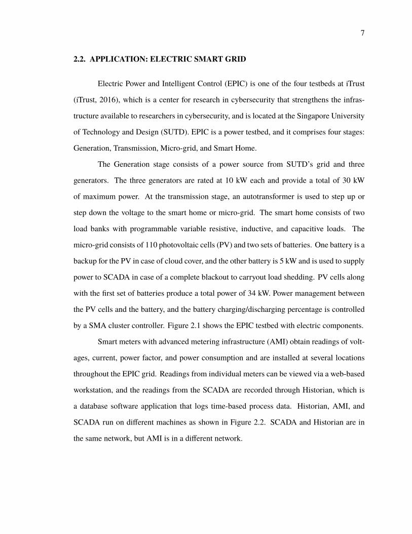
by a SMA cluster controller. Figure 2.1 shows the EPIC testbed with electric components.
Smart meters with advanced metering infrastructure (AMI) obtain readings of volt-
ages, current, power factor, and power consumption and are installed at several locations
throughout the EPIC grid. Readings from individual meters can be viewed via a web-based
workstation, and the readings from the SCADA are recorded through Historian, which is
a database software application that logs time-based process data. Historian, AMI, and
SCADA run on different machines as shown in Figure 2.2. SCADA and Historian are in
the same network, but AMI is in a different network.

8
Examples of critical information:
• Revolutions per minute (RPM): The RPM of the motor plays a key role in the power
grid system. It determines the voltage and frequency of the generated electricity. The
RPM value is regulated by the device called the variable speed drive (VSD). VSD
also provides the RPM values to the SCADA.
• Relay reading (RR): The RR from the IED/Relay contains the readings of voltage,
current, frequency, and power of the line in which the relay is present:
RR = (V, i, f R, P); (2.1)
where V-voltage, i-current, f R-frequency, and P-power.
For normal operation of EPIC, frequency should be 50 Hz and flow voltage should
be 415 V, with an allowed deviation of ±6%. If the frequency or voltage is above or
below the threshold, then the relay would send commands to trip the circuit breaker.
• Battery charging/discharging rule (CD) in percentage: The battery level percentage
at which the battery should only undergo charging and the percentage at which it can
discharge are set at the cluster controller. CD plays an important role in maintaining
health of the battery and having backup power in times of need.
• Circuit breaker status (CBS): The status of the circuit breaker determines whether or
not there will be flow of electricity further down the system. CBS is sent from the
relay to the control system.
• Circuit breaker command (CBC): The instruction for opening or closing the circuit
breaker sent from the control system to the circuit breaker. Before passing the CBC
from the control system, the relay modifies or simply transfers the CBC to the circuit
breaker based on the flow voltage.
Each of the critical information pieces have an information path associated with them.

9
Figure 2.1. EPIC- Single Line Diagram

10
Figure 2.2. EPIC- Network Diagram (iTrust, 2016). Examples for interpreting the devicesfrom diagram: i)MAMI2 -Microgrid stage Smart meter, device 2, ii) TIED4 - Transmissionstage Relay, device 4.

11
3. PROBLEM STATEMENT
Power grids are the most critical infrastructure of all countries. Power grids nowa-
days are largely smart and have many devices installed throughout the system to enable
easy operation and monitoring, which makes them more prone to cyber attacks. Cyber
attacks on such a critical CPS can cause a major disaster to a nation and have a serious
impact on its economy. In most of these attacks, the attacker has a good understanding of
the various devices in the CPS and designs malware for them. This malware carries out
a man-in-the-middle attack that fakes process control sensor signals so an infected system
does not shut down due to detected abnormal behavior. The malware also modifies the
data sent to the control system to make it look normal. So, there is no way for the operator
to know that the CPS is under attack. An attack of this kind happened in Iran (Falliere
et al., 2011). In this case, the Stuxnet was executed from the Siemens PLC and varied
the centrifuge’s rotor speed between high and low continuously in an attempt to damage
the centrifuge. The Stuxnet also sent recorded false positive reports that indicated normal
rotor speeds back to human operators. Because of this, the attack was undetected and many
centrifuges were damaged. In 2016, a malware caused a power outage for about an hour in
Ukraine that affected more than tens of thousands of households. The malware was found
to be capable of launching automated assaults against industrial control systems managing
the electric grid.
In this thesis, a model-based approach is carried out to find the vulnerable infor-
mation paths in the system. Invariants were generated through DeC and DaC methods and
implemented in the control system to identify Stuxnet-like attacks and abnormalities in a
smart grid.

12
4. VULNERABILITY ANALYSIS
In this thesis, a Stuxnet-like attack model is assumed in an electric microgrid.
The goal of these attacks is to disrupt system operation by confusing the system through
deception.
4.1. ATTACK MODEL
Stuxnet-like worms are malicious codes that can be injected into a system through
USB flash drives, shared networks, etc. Once Stuxnet is injected, it replicates to spread and
hides by faking a healthy working condition of the system. To do this, the worm targets
SCADA systems. In specific, it gets access to the programmable logic controller (PLC),
infects it with harmful operational commands and returns previously recorded normal
feedbacks to devices (sym, 2010). The undetectable mechanism of a Stuxnet-like worm
makes use of the security vulnerability of a system along with rootkits to make the attack
hard to be identified (Mueller and Yadegari, 2012). If an observer does not have valuation
function to ascertain whether the state of the system is true or false, then the system is
secure with respect to integrity. The operator cannot deduce if there is any fault or attack in
the system. Thus, secure paths within a system are bad.
4.2. INVARIANTS
An invariant is a logical predicate on system state and its truth value must not
change if it is satisfied by system execution. It is a property, function or quantity that stays
unchanged whilst a stated transformation is applied. Invariants were initially created for
cyber systems (Owicki and Gries, 1976). Lately, invariants have also been extended for
CPSs like power systems (Gamage et al., 2015) (Paul et al., 2014) and water treatment

13
systems (Adepu and Mathur, 2016). Defining invariants for CPSs are much harder than in
cyber processes because it requires a thorough understanding of the working of physical
and cyber components in the system.
The invariant equations in the EPIC testbed are executed at the control system.
Coupling MSDND and the invariant equations, the bounds on parameters measured in a
power grid can be minimized and the corrupt information path can be identified with a
better precision.

14
5. RELATED WORK
An attestation framework that makes use of physical process constraints as invariants
was proposed (Roth andMcMillin, 2016) to validate behaviors and identify attacks in cyber-
physical systems, in particular, a smart power grid. In the paper, false injection attacks are
concentrated as a typical attack method that commonly used against a smart grid. There
exist malicious cyber injection attacks that are proven to be hidden from pure software
detection. In such cases, physical verification plays an important role in exhibiting faulty
behaviors in the system.
The authors introduced a signature-based invariant protocol, 7-node attestation,
which is based on a manually summarized violation pattern on the law of the conservation
of energy. It examines neighboring household power migrations and setup invariants
calculated with actual power flow parameters, such as voltages and phase angles. Both
current measurements and saved conservations of such parameters are involved in the
computation of the invariant between a set of smart nodes. Under the proclaimed framework,
a fake supply attack where a malicious supplier pretends to increase the generation power to
meet the demand but actually violates the protocol can be deduced. Although the framework
introduced the physical layer attestation, due to the limitation of the invariant, a malicious
participant can be located only over specific topologies. It will also not work in network
partitions, which have limited communication between nodes.
MSDND approach helps in identifying integrity attacks within a system and has
been used in modeling security for several other cyber physical infrastructures like air
traffic control systems (Thudimilla and McMillin, 2017), chemical plants (Dunaka and
McMillin, 2017) and vehicle platoon systems (Kanteti, 2017).

15
6. SECURITY ANALYSIS AND INVARIANT GENERATION
6.1. DESIGN-CENTRIC APPROACH
MSDND Analysis. In MSDND analysis, the information flow paths of different
critical information pieces in the system are analyzed in the proofs using BIT logic. Mathe-
matical analysis of each piece of information is performed from the source to the destination
(control system) through different security domains in which the information gets passed.
The point at which the information can get corrupted is identified, and invariants are gen-
erated to create a valuation function that helps detect the attack.
There are five different types of critical information in the testbed, as seen in Section
2.2. Each type of critical information has an information path associated with it. The secu-
rity domains for each of the information paths is shown in Figures 6.1, 6.2, 6.3 and 6.4. In
the following proofs, invariants are used to break theMSDND security of an integrity attack.
Figure 6.1. Security domains of ‘RPM’ information path

16
Figure 6.2. Security domains of ‘RR and CBS’ information path
Figure 6.3. Security domains of ‘CD’ information path
Assumption. RR contains various values as mentioned in Equation 2.1. For a
successful attack, the attacker needs to change all the values in RR proportionately. This
assumption has been used in theDeC approach for generating invariants. Only the frequency
values are considered in generating the invariant. If the frequency of RR fails the invariant
equation, then the other values will also fail.

17
Figure 6.4. Security domains of ‘CBC’ information path
Macros. The following macro is used in the theorems defined below.,
IBT1,2Val = I1,2Val; /*2 reported to 1 that Val is true*/
B1I1,2Val; /*1 believes that Val is true*/
T1,2Val; /*The trust that 1 has on 2 about the information Val*/
B1I1,2 Val ∧ T1,2 Val → B1 Val; /*1 believes that Val is correct*/
• Single-point attacks
Analysis of vulnerability in RPM information path.
Theorem 1. The RPM reading RPM from VSD is MSDND secure at the Control System
(CS) when RPM is not normal but the reading is normal.
Proof. Here the RPM reading from VSD is modified by the Stuxnet and sent to the CS.
1. ∼RPM = true; The RPM is not normal
2. w |= VVSD∼RPM (w) = true; RPM reading is not normal at the VSD
3. IBTStuxnet,VSD ∼RPM; Stuxnet intercepts the abnormal RPM sent by VSD to PLC
4. w |= VStuxnet∼RPM (w) = true; Stuxnet observes that RPM is abnormal

18
5. IBTPLC,Stuxnet RPM; Stuxnet modifies RPM to make it look normal and sends it to
PLC and PLC believes it
6. w |= V PLCRPM (w) = true; RPM appears normal in PLC world
7. IBTCS,PLC RPM; PLC tells CS that RPM is normal and CS believes it
8. w |= VCSRPM (w) = true; CS believes that RPM is normal, it does not have valuation
function to verify it
9. MSDND(ES):∃w ∈W ` [ ( SRPM ⊕ S∼RPM ) ] ∧ [ w |= ( @VCS∼RPM( w) ∧@VCS
RPM( w) ) ]
The CS believes the false positive RPM reading reported by the Stuxnet and believes
that everything is normal. Therefore RPM information is MSDND secure from the CS.
There are three such MSDND secure paths in the system as shown in Table 6.1.
Theorem 2. The RPM reading RPM from VSD is not MSDND secure when RPM is not
normal but the reading is normal and an invariant on the frequency f and RPM are
considered.
Proof. Let us assume the frequency reading f from the AMI is correct. Let the invariant
iRPM: RPM = 30 f be in the control system. The invariant is derived from the equation,
RPM =(120 × f )
P, where P is the number of poles in the motor, here P = 4.
1. ∼RPM = true; The RPM is not normal
2. w |= VVSD∼RPM (w) = true; RPM reading is not normal at the VSD
3. IBTStuxnet,VSD ∼RPM; Stuxnet intercepts the abnormal RPM sent by VSD to PLC
4. w |= VStuxnet∼RPM (w) = true; Stuxnet observes that RPM is abnormal
5. IBTPLC,Stuxnet RPM; Stuxnet modifies RPM to make it look normal and sends it to
PLC and PLC believes it

19
Table 6.1. Summary of MSDND analysis for RPM information path
S.No. MSDND Secure Paths Invariant Available1 VSD1→SPLC→CPLC→CS Yes2 VSD2→SPLC→CPLC→CS Yes3 VSD3→SPLC→CPLC→CS Yes
6. w |= V PLCRPM (w) = true; RPM appears normal in PLC world
7. IBTCS,PLC RPM; PLC tells CS that RPM is normal and CS believes it
8. ∼RPM =⇒ ∼ f ; when RPM is not normal it affects the RR
9. IBTCS,AMI ∼ f ; CS obtains the f reading from smart meter and believes it
10. ∼iRPM =⇒ ∼RPM; from our assumption that the frequency reading f from the
AMI is correct and the invariant iRPM , the CS deduces that RPM is not normal
11. (SiRPM , SRPM) = S”; System is working normally if and only if S” is true
12. w |= VCS∼RPM (w) = true; CS now has deduced that RPM is abnormal
13. ∼MSDND(ES): ∃w ∈W ` [ ( S” ⊕ S∼RPM ) ] ∧ [ w |= (∃VCS∼RPM( w) ∧ @VCS
RPM( w) ) ]
The system is not MSDND secure as we have valuation function for normal working
of the system as shown in Figure 6.5, and fault/threat can be detected. This can be used to
break three MSDND secure paths in the system.
Analysis of vulnerability in CD information path.
Theorem 3. The battery charging/discharging percentage CD set at the cluster controller
(CC) is MSDND secure at the control system (CS)
Proof. 1. ∼CD = true; charging/discharging percentage set is not normal

20
Figure 6.5. Information flow when RPM is abnormal and invariant is used. Attack modelfor this is explained in Theorem 1 and attack detection is explained in Theorem 2.
2. w |= VCC∼CD (w) = true; CD is not normal in CC world
3. IBTStuxnet,CC ∼CD; Stuxnet intercepts the abnormal CD sent by Cluster controller to
CS
4. w |= VStuxnet∼CD (w) = true; Stuxnet observes that CD is abnormal
5. IBTCS,StuxnetCD; Stuxnet reports that the CD is normal to CS and CS believes it
6. w |= VCSCD(w) = true; CS believes CD to be normal
7. MSDND(ES): ∃ w ∈W ` [ ( St ⊕ S∼t ) ] ∧ [ w |= ( @ VCS∼CD( w) ∧ @ VCS
CD( w) ) ]
The control system believes that battery charging/discharging level set in the cluster
controller is in desired range. TheCD cannot be evaluated at the CS and hence it isMSDND
secure. Moreover, there are no alternate information paths to define invariant for this path
as seen in Figure 6.6.

21
Figure 6.6. Information flow when CD is abnormal. Attack model for this is explained inTheorem 3.
Analysis of vulnerability in RR information path.
Theorem 4. RR (within threshold or not) information is MSDND secure when the flow
voltage is normal but the circuit breaker trips
Proof. Here, the voltage that flows through the relay is within threshold but still the circuit
breaker is tripped, i.e., CBS = open.
1. f V = true; The flow voltage is within threshold
2. w |= V Relayf V (w) = true; The relay observes that the voltage is normal
3. f V =⇒ CBS; When the flow voltage is normal, the relay sends the CB the same
command that SCADA sends to CB, so here it directs CB to remain closed
4. CBS = true; CBS is normal
5. w |= V RelayCBS (w) = true; CBS is normal in relay world
6. IBTStuxnet,Relay CBS; Stuxnet intercepts the normal CBS sent by Relay to CB
7. w |= VStuxnetCBS (w) = true; Stuxnet observes that CBS is normal

22
8. IBTCB,Stuxnet ∼CBS; The Stuxnet instructs the CB to open even though the flow
voltage is normal
9. CBS=open =⇒ RR = 0; When CB is open the relay reading is zero
10. ∼RR = true; RR is now not normal
11. w |= V Relay∼RR (w) = true; Relay observes that RR is not normal
12. IBTPLC,Relay ∼RR; Relay tells PLC that RR is not normal and PLC believes it
13. w |= V PLC∼RR (w) = true; RR is not normal in PLC world
14. IBTCS,PLC ∼RR; PLC tells CS that RR is not normal and CS believes it
15. w |= VCS∼RR (w) = true; RR is abnormal in CS, CS believes it is because of abnormal
flow voltage
16. MSDND(ES): ∃ w ∈W ` [ ( SRR ⊕ S∼RR ) ] ∧ [ w |= ( @ VCS∼RR( w) ∧ @ VCS
RR ( w) ) ]
The RR reading received at the CS are all zero hence it is not possible to deduce
at the CS whether the CB trip was because of voltage beyond threshold or because of
fault/attack. Hence, the system is MSDND secure. There are eleven such MSDND secure
paths in the system as listed in the Table 6.3.
Theorem 5. RR (within threshold or not) information is not MSDND secure if the invariant
is used when the flow voltage is normal but the circuit breaker trips
Proof. Here the CBS = open and hence RR=0. To check whether the trip was because of
fault/attack we take the readings pRR from the Relays that are present immediately before
the relay that got tripped. Table 6.2 lists the relay readings that need to be used for each of
the relays that has zero reading because of tripping. If two relays are listed then any one of
them that does not have zero reading can be used. ProjpFR(pRR) = p f R. Let us assume

23
Table 6.2. Relay association with previous closest relays
Relay with zero reading Relay reading to useGIED1 Not availableGIED2 SIED1TIED1 GIED1/GIED2TIED2 TIED1TIED4 MIED1/MIED2MIED1 GIED1/GIED2MIED2 GIED1/GIED2SIED1 TIED2/TIED4SIED2 TIED2/TIED4SIED3 TIED2/TIED4SIED4 TIED2/TIED4
the frequency reading pFR from the closest previous relay is accurate. Let the invariant
iFT hresh : 47 < pFR < 53 be in the control system. The normal operating frequency of
the EPIC system is 50 Hz with an allowed deviation of ± 6%.
1. f V = true; The flow voltage is within threshold
2. w |= V Relayf V (w) = true; The relay observes that the voltage is normal
3. f V =⇒ CBS; When the flow voltage is normal, the relay sends the CB the same
command that SCADA sends to CB, so here it directs CB to remain closed
4. CBS = true; CBS is normal
5. w |= V RelayCBS (w) = true; CBS is normal in relay world
6. IBTStuxnet,Relay CBS; Stuxnet intercepts the normal CBS sent by Relay to CB
7. w |= VStuxnetCBS (w) = true; Stuxnet observes that CBS is normal
8. IBTCB,Stuxnet ∼CBS; The Stuxnet instructs the CB to open even though the flow
voltage is normal

24
9. CBS=open =⇒ RR=0; When CB is open RR is zero
10. ∼RR = true; RR is now not normal
11. w |= V Relay∼RR (w) = true; Relay observes that RR is not normal
12. IBTPLC,Relay ∼RR; Relay tells PLC that RR is not normal and PLC believes it
13. w |= V PLC∼RR (w) = true; RR is not normal in PLC world
14. IBTCS,PLC ∼RR; PLC tells CS that RR is not normal and CS believes it
15. w |= VCS∼RR (w) = true; RR is abnormal in the CS world, CS believes it is because of
abnormal flow voltage
16. IBTPLC,Relay pRR; pRR is extracted from previous closest relay to the relay in which
zero reading was shown
17. w |= V PLCpRR (w) = true; pRR is normal in PLC world
18. IBTCS,PLC pRR; PLC tells CS that pRR is normal and CS believes it
19. iFT hresh =⇒ pFR =⇒ RR (∵ProjpFR(pRR) = pFR); From our assumption that
the frequency reading pFR from the closest previous relay is accurate and the invariant
iFT hresh, the CS deduces that RR is normal
20. S” = (SiFT hresh, SRR) ; System is working normally if and if only S” is true
21. w |= VCSRR (w) = true; RR is normal in the CS world
22. ∼MSDND(ES): ∃ w ∈W ` [ ( S” ⊕ S∼RR ) ] ∧ [ w |= (∃ VCS∼RR( w) ∧ @ VCS
RR ( w) ) ]
When the RR reading received at the CS are all zero but pRR readings are all within
threshold during this period, then we can deduce that the trip in the CB was not because of
abnormal flow voltage, but because of fault/attack. Hence, the system is no longer MSDND

25
Figure 6.7. Information flow when RR is normal but the CB trips, and invariant is consid-ered. Attack model for this is explained in Theorem 4 and attack detection is explained inTheorem 5.
secure as seen in Figure 6.7. This theorem can be used to break ten MSDND secure paths
out of the eleven. The MSDND secure path when GIED1 RR shows zero can not be broken,
because there are no relays present before it. This is a design flaw in the system.
Theorem 6. RR (within threshold or not) information is MSDND secure when the flow
voltage is abnormal but the circuit breaker does not trip
Proof. Here the voltage that flows through the relay is not within threshold, but the circuit
breaker does not trip, i.e., CBS = closed. The Stuxnet changes the circuit breaker command
sent from the relay to the CB (i.e., open to closed) and masks the RR sent from the relay to
the CS.
1. ∼ f V = true; The flow voltage is not within threshold
2. w |= V Relay∼ f V (w) = true; The relay observes that the voltage is not within threshold

26
3. ∼ f V =⇒ ∼CBS; When the flow voltage is not normal, the relay ignores the SCADA
command to CB and directs it to open
4. ∼ CBS = true; CBS at relay is different from CBS at SCADA
5. w |= V Relay∼CBS (w) = true; CBS is not normal at the relay
6. IBTStuxnet,Relay ∼CBS; Stuxnet intercepts the abnormal CBS sent by relay to CB
7. w |= VStuxnet∼CBS (w) = true; Stuxnet knows that the CBS is not normal
8. IBTCB,Stuxnet CBS; Stuxnet modifies the CBS and instructs the CB that it is normal,
CB believes it
9. ∼ f V =⇒ ∼RR; The flow voltage is not normal so that reflects RR
10. ∼RR = true; RR is not normal
11. w |= V Relay∼RR (w) = true; RR is abnormal in relay world
12. IBTStuxnet,Relay ∼RR; Stuxnet intercepts the abnormal RR sent by relay to CB
13. w |= VStuxnet∼RR (w) = true; Stuxnet observes that RR is abnormal
14. IBTPLC,Stuxnet RR; Stuxnet modifies RR to make it look normal and transmits it to
PLC and PLC believes it
15. w |= V PLCRR (w) = true; RR looks normal in PLC world
16. IBTCS,PLC RR; PLC tells CS that RR is normal and CS believes it
17. w |= VCSRR (w) = true; CS believes that RR is normal and system is normally working
18. MSDND(ES): ∃ w ∈W ` [ ( SRR ⊕ S∼RR ) ] ∧ [ w |= ( @ VCS∼RR( w) ∧ @ VCS
RR ( w) ) ]

27
The RR readings received at the CS are all normal as the Stuxnet had sent false
positives. Hence, it is not possible to deduce at the CS whether the RR is within threshold
or not. Thus, the system is MSDND secure. There are eleven such MSDND secure paths
in the system as listed in Table 6.3.
Theorem 7. The Relay reading RR (within threshold or not) information is not MSDND
securewhen the flow voltage is abnormal but the circuit breaker does not trip if the invariants
are considered.
Proof. Let us assume the frequency reading f from the AMI is correct. Let f R be the
frequency reading from the relay. Let the invariant iFreq : f == f R and 47 < f < 53 be
in the CS.
1. ∼ f V = true; The flow voltage is not within threshold
2. w |= V Relay∼ f V (w) = true; The relay observes that the voltage is not within threshold
3. ∼ f V =⇒ ∼CBS; When the flow voltage is not normal, the relay ignores the SCADA
command to CB and directs it to open
4. ∼ CBS = true; CBS at relay is different from CBS at SCADA
5. w |= V Relay∼CBS (w) = true; CBS is not normal at the relay
6. IBTStuxnet,Relay ∼CBS; Stuxnet intercepts the abnormal CBS sent by relay to CB
7. w |= VStuxnet∼CBS (w) = true; Stuxnet knows that the CBS is not normal
8. IBTCB,Stuxnet CBS; Stuxnet modifies the CBS and instructs the CB that it is normal,
CB believes it
9. ∼ f V =⇒ ∼RR; The flow voltage is not normal so that reflects RR
10. ∼RR = true; RR is not normal

28
11. w |= V Relay∼RR (w) = true; RR is abnormal in relay world
12. IBTStuxnet,Relay ∼RR; Stuxnet intercepts the abnormal RR sent by relay to CB
13. w |= VStuxnet∼RR (w) = true; Stuxnet observes that RR is abnormal
14. IBTPLC,Stuxnet RR; Stuxnet modifies RR to make it look normal and transmits it to
PLC and PLC believes it
15. w |= V PLCRR (w) = true; RR looks normal in PLC world
16. IBTCS,PLC RR; PLC tells CS that RR is normal and CS believes it
17. ∼ f V =⇒ ∼ f ; When f V is abnormal, even the AMI readings are abnormal
18. IBTCS,AMI ∼ f ; CS obtains the f reading from AMI and believes it
19. ∼iFreq =⇒ ∼ f R =⇒ ∼RR (∵ Proj f R(RR) = f R); From our assumption that the
frequency reading f from the AMI is correct and the invariant iFreq, the CS deduces
that RR is abnormal
20. S” = (Sinvariant , SRR) ; System is working normally if and if only S” is true
21. w |= VCS∼RR (w) = true; CS with help of invariant knows that RR is not normal
22. ∼MSDND(ES): ∃ w ∈W ` [ ( S” ⊕ S∼RR ) ] ∧ [ w |= (∃ VCS∼RR( w) ∧ @ VCS
RR ( w) ) ]
When the frequency reading from the AMI and relay does not match, and when the
frequency reading from the AMI is not within threshold, then we can deduce at the CS that
the RR was not within threshold, but still the relay did not trip. This is demonstrated in
Figure 6.8. Thus, the system is not MSDND secure. Using this invariant, all the eleven
such MSDND secure paths in the system listed in Table 6.3 can be broken, including the
path involving GIED1.

29
Table 6.3. Summary of MSDND analysis for RR information path
S.No. MSDND Secure Paths Invariant Available1 GIED1→GPLC→CPLC→CS No2 GIED2→GPLC→CPLC→CS Yes3 MIED1→MPLC→CPLC→CS Yes4 MIED2→MPLC→CPLC→CS Yes5 TIED1→TPLC→CPLC→CS Yes6 TIED2→TPLC→CPLC→CS Yes7 TIED4→TPLC→CPLC→CS Yes8 SIED1→SPLC→CPLC→CS Yes9 SIED2→SPLC→CPLC→CS Yes10 SIED3→SPLC→CPLC→CS Yes11 SIED4→SPLC→CPLC→CS Yes
Analysis of vulnerability in CBS information path.
Theorem 8. The Circuit breaker status CBS is MSDND secure at the CS when the CB is
open but SCADA shows it as closed and also when the CB is closed but SCADA shows it as
open.
Proof. Here the Stuxnet changes the true value of the CBS. It changes it from true to false
or from false to true.
1. CBS = true; CBS is normal
2. w |= VCBCBS (w) = true; CBS is normal in CB world
3. IBTRelay,CB CBS; CB tells relay that CBS is normal and Relay believes it
4. w |= V RelayCBS (w) = true; CBS is normal in relay world
5. IBTPLC,Relay CBS; relay tells PLC that CBS is normal and PLC believes it
6. w |= V PLCCBS (w) = true; CBS is normal in PLC world
7. IBTStuxnet,PLC CBS; Stuxnet intercepts the normal CBS sent by PLC to CS

30
Figure 6.8. Information flow when RR is abnormal but CB does not trip, and invariantis considered. Attack model for this is explained in Theorem 6 and attack detection isexplained in Theorem 7.
8. ∼CBS = true; The Stuxnet reverses the CBS from the original status
9. w |= VStuxnet∼CBS (w) = true; The Stuxnet knows that it has altered the CBS from its
original status
10. IBTCS,Stuxnet CBS; Stuxnet reports the CS that the CBS is normal and CS believes it
11. w |= VCS∼CBS (w) = false; CS does not know that CBS is not normal
12. MSDND(ES): ∃ w ∈W ` [ ( SCBS ⊕ S∼CBS ) ] ∧ [ w |= ( @ VCS∼CBS( w) ∧ @ VCS
CBS( w) ) ]
The Stuxnet modifies the actual CBS received from the PLC and sends a false value
to the CS and the CS believes it to be the true state of the CB. Hence, it is not possible to
deduce at the CS whether the CBS is correct or not. Thus, the system is MSDND secure.
There are thirty such MSDND secure paths in the system, fifteen when the CB is open and
the SCADA shows it as closed, and fifteen when the CB is closed and the SCADA shows it
as open. There are two possible cases for each of the listed paths in Table 6.4.

31
Theorem 9. CBS is not MSDND secure at the CS when the CB is open but SCADA shows
it as closed if the invariant is taken into consideration.
Proof. Let us assume that the relay reading RR is correct. Let f R be the frequency reading
from the relay. Let the invariant iCBClosedCheck : CBS == closed and f R , 0 be in
the CS
1. CBS = true; CBS is normal and its value is open
2. w |= VCBCBS (w) = true; CBS is normal in CB world
3. IBTRelay,CB CBS; CB tells relay that CBS is normal and relay believes it
4. w |= V RelayCBS (w) = true; CBS is normal in relay world
5. IBTPLC,Relay CBS; relay tells PLC that CBS is normal and PLC believes it
6. w |= V PLCCBS (w) = true; CBS is normal in PLC world
7. IBTStuxnet,PLC CBS; Stuxnet intercepts the normal CBS sent by PLC to CS
8. ∼CBS = true; The Stuxnet changes the CBS status as closed from open
9. w |= VStuxnet∼CBS (w) = true; The Stuxnet knows that it has altered the CBS from its
original status
10. IBTCS,Stuxnet CBS; The Stuxnet reports the CS that the CBS is open and it is normal
11. w |= VCS∼CBS (w) = false; CS does not know that CBS is not normal
12. RR = true; RR is normal
13. w |= V RelayRR (w) = true; RR is normal in relay world
14. IBTPLC,RelayRR; relay tells PLC that RR is normal and PLC believes it
15. w |= V PLCRR (w) = true; RR is normal in PLC world

32
16. IBTCS,PLC RR; PLC tells CS that RR is normal and CS believes it
17. w |= VCSRR (w) = true; RR is normal in CS world
18. Proj f R(RR) = f R,∼iCBClosedCheck =⇒ ∼CBS; when the invariant iCBClosedCheck
fails, CS deduces that CBS is not normal
19. w |= VCS∼CBS (w) = true; CS world now has deduced that CBS is abnormal
20. S” = (SiCBClosedCheck , SCBS) ; System is working normally if and only if S” is true
21. ∼MSDND(ES): ∃ w ∈W ` [ ( S” ⊕ S∼CBS ) ] ∧ [ w |= (∃ VCBS∼CBS( w) ∧ @ VCS
CBS( w) ) ]
When the CB is closed, the f R should not be zero, if f R is zero then that indicates
that the CBS at the CS is not correct. Hence, the system is no longer MSDND secure. This
is demonstrated in Figure 6.9. This theorem can be used to break twelve MSDND secure
paths in the system out of the fifteen as shown in Table 6.4. The three CB Q1-1, Q1-2 and
Q2 does not have a relay or a smart meter next to them to validate their state through this
invariant.
Note: For the circuit breaker Q2A there are no relays next to it, wemake use of the frequency
reading from the AMI in the invariant iCBClosedCheck instead of f R.
Theorem 10. The Circuit breaker state CBS is not MSDND secure at the CS when the CB
is closed but SCADA shows it as open if the invariant is taken into consideration.
Proof. Let us assume that the relay reading RR is correct. Let f R be the frequency reading
from the relay. Let the invariant iCBOpenCheck : CBS == open and f R = 0 be in the
CS
1. CBS = true; CBS is normal and its value is closed
2. w |= VCBCBS (w) = true; CBS is normal in CB world

33
Table 6.4. Summary of MSDND analysis for CBS information path
S.No. MSDND Secure Paths Invariant Available1 Q1→GIED1→GPLC→CPLC→CS Yes2 Q1A→GIED2→GPLC→CPLC→CS Yes3 Q1-1→GPLC→CPLC→CS No4 Q1-2→GPLC→CPLC→CS No5 Q2→MPLC→CPLC→CS No6 Q2A→MPLC→CPLC→CS Yes7 Q2B→MIED1→MPLC→CPLC→CS Yes8 Q2C→MIED2→MPLC→CPLC→CS Yes9 Q1-3→TIED1→TPLC→CPLC→CS Yes10 Q3→TIED2→TPLC→CPLC→CS Yes11 Q2-1→TIED4→TPLC→CPLC→CS Yes12 Q3-4→SIED1→SPLC→CPLC→CS Yes13 Q3-3→SIED2→SPLC→CPLC→CS Yes14 Q3-2→SIED3→SPLC→CPLC→CS Yes15 Q3-1→SIED4→SPLC→CPLC→CS Yes
3. IBTRelay,CB CBS; CB tells relay that CBS is normal and relay believes it
4. w |= V RelayCBS (w) = true; CBS is normal in relay world
5. IBTPLC,Relay CBS; relay tells PLC that CBS is normal and PLC believes it
6. w |= V PLCCBS (w) = true; CBS is normal in PLC world
7. IBTStuxnet,PLC CBS; Stuxnet intercepts the normal CBS sent by PLC to CS
8. ∼CBS = true; The Stuxnet changes the CBS status as open from closed
9. w |= VStuxnet∼CBS (w) = true; The Stuxnet knows that it has altered the CBS from its
original status
10. IBTCS,Stuxnet CBS; The Stuxnet reports the CS that the CBS is closed and CBS is
normal

34
11. w |= VCS∼CBS (w) = false; CS does not know that CBS is not normal
12. RR = true; RR is normal
13. w |= V RelayRR (w) = true; RR is normal in relay world
14. IBTPLC,RelayRR; relay tells PLC that RR is normal and PLC believes it
15. w |= V PLCRR (w) = true; RR is normal in PLC world
16. IBTCS,PLC RR; PLC tells CS that RR is normal and CS believes it
17. w |= VCSRR (w) = true; RR is normal in CS world
18. Proj f R(RR) = f R,∼iCBOpenCheck =⇒ ∼CBS; when the invariant iCBOpenCheck
fails, CS deduces that CBS is not normal
19. w |= VCS∼CBS (w) = true; CS world now has deduced that CBS is abnormal
20. S” = (Sinvariant , SCBS) ; System is working normally if and only if S” is true
21. ∼MSDND(ES): ∃ w ∈W ` [ ( S” ⊕ S∼CBS ) ] ∧ [ w |= (∃ VCBS∼CBS( w) ∧ @ VCS
CBS( w) ) ]
When the CB is open, the f R should be zero; if f R is not zero, then that indicates
that the CBS at the CS is not correct and it is actually closed. Hence the system is no longer
MSDND secure. This is demonstrated in Figure 6.9. This theorem can be used to break
twelve MSDND secure paths in the system out of the fifteen as shown in Table 6.4. The
three CB Q1-1, Q1-2 and Q2 does not have a relay or a smart meter next to them to validate
their state through this invariant.
Note: For the circuit breaker Q2A there are no relays next to it, wemake use of the frequency
reading from the AMI in the invariant iCBOpenCheck instead of f R.

35
Figure 6.9. Information flow when CBS is abnormal but SCADA shows the inverse ofit, and invariant is considered. Attack model for this is explained in Theorem 8, attackdetection when CB is originally open is explained in Theorem 9, and attack detection whenCB is originally closed is explained in Theorem 10.
Analysis of vulnerability in CBS and RR information path.
Theorem 11. The Circuit breaker statusCBS and the relay reading RR are MSDND secure
at the CS when the CS commands the CB to open but CB is closed and also when the CS
commands the CB to close but CB is open.
Proof. Let CBC represent the command sent by the CS to the CB.
1. CBC = true; CBC is normal
2. w |= VCSCBC (w) = true; CBC is normal in CS world
3. IBTPLC,CS CBC; CS sends CBC to PLC and PLC believes it
4. w |= V PLCCBC (w) = true; CBC is true in PLC world
5. IBTStuxnet,PLC CBC; Stuxnet intercepts the normal CBC sent by PLC to relay
6. ∼ CBC = true; The Stuxnet reverses the CBC
7. w |= VStuxnet∼CBC (w) = true; The Stuxnet knows that the CBC is not correct

36
8. IBTRelay,Stuxnet CBC; The Stuxnet reports the Relay that CBC is normal and Relay
believes it
9. w |= V Relay∼CBC (w) = false; relay does not know that CBC is abnormal
10. IBTCB,Relay CBC; relay sends CBC to CB and CB believes it to be normal
11. w |= VCB∼CBC (w) = false; CB does not know that CBC is abnormal
12. ∼CBC =⇒ ∼CBS,∼RR; When the CBC is not normal then even the CBS and RR
will not be normal
13. ∼CBS,∼RR = true; CBS and RR are not normal
14. w |= V Relay∼CBS,∼RR (w) = true; CBS and RR are not normal in relay world
15. IBTStuxnet,Relay ∼CBS,∼RR; Stuxnet intercepts the abnormal CBS and RR sent by
relay to PLC
16. w |= VStuxnet∼CBS,∼RR (w) = true; Stuxnet knows that CBS and RR are abnormal
17. IBTPLC,Stuxnet CBS, RR; The Stuxnet changes the CBS and RR values and tells the
PLC that it is normal
18. w |= V PLC∼CBS,∼RR (w) = false; CBS and RR are abnormal but in PLC world it appears
normal
19. IBTCS,PLC CBS, RR; PLC tells CS that CBS and RR are normal and CS believes that
20. w |= VCSCBS,RR (w) = true; In the CS world CBS and RR are true
21. MSDND(ES): ∃ w ∈ W ` [ ( SCBS,RR ⊕ S∼CBS,RR ) ] ∧ [ w |= ( @ VCS∼CBS,RR( w) ∧ @
VCSCBS,RR( w) ) ]

37
The Stuxnet reverses the actual CB command CBC sent from the CS and then sends
false positive RR and CBS to the CS. it is not possible to deduce at the CS whether the
CBS and RR are correct or not. Thus, the system is MSDND secure. There are thirty such
MSDND secure paths in the system, fifteen when the CS instructs open but CB is closed,
and fifteen when the CS instructs closed but CB is open. There are two possible cases for
each of the listed paths in Table 6.4.
Theorem 12. The Circuit breaker status CBS and the relay reading RR are not MSDND
secure at the CS when the CS commands the CB to open but CB is closed if the invariants
are considered.
Proof. Let us assume that the frequency reading f from the AMI is correct. Let f R be the
frequency reading in RR and let the invariant iCBRROpen : CBS == open and f == 0
and f == f R be the invariant in the CS.
1. CBC = true; CBC is normal
2. w |= VCSCBC (w) = true; CBC is normal in CS world
3. IBTPLC,CS CBC; CS sends CBC to PLC and PLC believes it
4. w |= V PLCCBC (w) = true; CBC is true in PLC world
5. IBTStuxnet,PLC CBC; Stuxnet intercepts the normal CBC sent by PLC to relay
6. ∼ CBC = true; The Stuxnet reverses the CBC
7. w |= VStuxnet∼CBC (w) = true; The Stuxnet knows that the CBC is not correct
8. IBTRelay,Stuxnet CBC; The Stuxnet reports the Relay that CBC is normal and Relay
believes it
9. w |= V Relay∼CBC (w) = false; relay does not know that CBC is abnormal

38
10. IBTCB,Relay CBC; relay sends CBC to CB and CB believes it to be normal, here
CBC=open
11. w |= VCB∼CBC (w) = false; CB does not know that CBC is abnormal
12. ∼CBC =⇒ ∼CBS,∼RR; When the CBC is not normal then even the CBS and RR
will not be normal
13. ∼CBS,∼RR = true; CBS and RR are not normal
14. w |= V Relay∼CBS,∼RR (w) = true; CBS and RR are not normal in relay world
15. IBTStuxnet,Relay ∼CBS,∼RR; Stuxnet intercepts the abnormal CBS and RR sent by
relay to PLC
16. w |= VStuxnet∼CBS,∼RR (w) = true; Stuxnet knows that CBS and RR are abnormal
17. IBTPLC,Stuxnet CBS, RR; The Stuxnet changes the CBS and RR values and tells the
PLC that it is normal
18. w |= V PLC∼CBS,∼RR (w) = false; CBS and RR are abnormal but in PLC world it appears
normal
19. IBTCS,PLC CBS, RR; PLC tells CS that CBS and RR are normal and CS believes that
20. w |= VCSCBS,RR (w) = true; In the CS world CBS and RR are true
21. ∼CBS =⇒ ∼ f ; as CBS is not normal, the AMI readings are also not normal
22. IBTCS,AMI ∼ f ; We obtain the frequency reading from the AMI at the CS
23. w |= VCS∼ f (w) = true; f is not normal in CS world
24. Proj f R(RR)= f R;
25. ∼iCBRROpen =⇒ ∼CBS,∼RR; when the invariant iCBRROpen fails, CS deduces
that CBS and RR are not normal

39
26. w |= VCS∼CBS,∼RR (w) = true; CS world now has deduced that CBS and RR are not
normal
27. S” = (SiCBRROpen, SCBS,RR) ; System is working normally if and only if S” is true
28. ∼MSDND(ES): ∃ w ∈ W ` [ ( S” ⊕ S∼CBS,RR ) ] ∧ [ w |= (∃ VCS∼CBS,RR( w) ∧ @
VCSCBS,RR( w) ) ]
If the CB is open, then f should be zero; if the RR is true, then it should match with
the corresponding AMI reading. When this is not true, we can deduce that the RR and the
CBS at the CS are incorrect as shown in Figure 6.10. This invariant can be used to break
eleven out of the fifteen MSDND secure paths. The four circuit breakers Q1-1, Q1-2, Q2
and Q2A does not have a relay next to them to validate their state through the invariant
iCBRROpen. The paths that are broken in Table 6.4 holds, but the line item 6 involving
Q2A does not have an invariant.
Theorem 13. The Circuit breaker status CBS and the relay reading RR are not MSDND
secure at the CS when the CS commands the CB to close but CB is open if the invariants
are considered.
Proof. Let us assume that the frequency reading f from the AMI is correct. Let f R be the
frequency reading in RR and let the invariant iCBRRClose : CBS == closed and f , 0
and f == f R be the invariant in the CS.
1. CBC = true; CBC is normal
2. w |= VCSCBC (w) = true; CBC is normal in CS world
3. IBTPLC,CS CBC; CS sends CBC to PLC and PLC believes it
4. w |= V PLCCBC (w) = true; CBC is true in PLC world
5. IBTStuxnet,PLC CBC; Stuxnet intercepts the normal CBC sent by PLC to relay

40
6. ∼ CBC = true; The Stuxnet reverses the CBC
7. w |= VStuxnet∼CBC (w) = true; The Stuxnet knows that the CBC is not correct
8. IBTRelay,Stuxnet CBC; The Stuxnet reports the Relay that CBC is normal and Relay
believes it
9. w |= V Relay∼CBC (w) = false; relay does not know that CBC is abnormal
10. IBTCB,Relay CBC; relay sends CBC to CB and CB believes it to be normal, here
CBC=open
11. w |= VCB∼CBC (w) = false; CB does not know that CBC is abnormal
12. ∼CBC =⇒ ∼CBS,∼RR; When the CBC is not normal then even the CBS and RR
will not be normal
13. ∼CBS,∼RR = true; CBS and RR are not normal
14. w |= V Relay∼CBS,∼RR (w) = true; CBS and RR are not normal in relay world
15. IBTStuxnet,Relay ∼CBS,∼RR; Stuxnet intercepts the abnormal CBS and RR sent by
relay to PLC
16. w |= VStuxnet∼CBS,∼RR (w) = true; Stuxnet knows that CBS and RR are abnormal
17. IBTPLC,Stuxnet CBS, RR; The Stuxnet changes the CBS and RR values and tells the
PLC that it is normal
18. w |= V PLC∼CBS,∼RR (w) = false; CBS and RR are abnormal but in PLC world it appears
normal
19. IBTCS,PLC CBS, RR; PLC tells CS that CBS and RR are normal and CS believes that
20. w |= VCSCBS,RR (w) = true; In the CS world CBS and RR are true

41
21. ∼CBS =⇒ ∼ f ; as CBS is not normal, the AMI readings are also not normal
22. IBTCS,AMI ∼ f ; We obtain the frequency reading from the AMI at the CS
23. w |= VCS∼ f (w) = true; f is not normal in CS world
24. Proj f R(RR)= f R;
25. ∼iCBRRClose =⇒ ∼CBS,∼RR; when the invariant iCBRRClose fails, CS deduces
that CBS and RR are not normal
26. w |= VCS∼CBS,RR (w) = true; CS world now has deduced that CBS and RR are abnormal
27. S” = (SiCBRRClose, SCBS,RR) ; System is working normally if and only if S” is true
28. ∼MSDND(ES): ∃ w ∈ W ` [ ( S” ⊕ S∼CBS,RR ) ] ∧ [ w |= (∃ VCS∼CBS,RR( w) ∧ @
VCSCBS,RR( w) ) ]
If the CB is closed, then f should not be zero; if the RR is true, then it should match
with the corresponding AMI reading. When this is not true, we can deduce that the RR
and the CBS at the CS are incorrect as shown in Figure 6.10. This invariant can be used to
break eleven out of the fifteen MSDND secure paths. The four circuit breakers Q1-1, Q1-2,
Q2 and Q2A does not have a relay next to them to validate their state through the invariant
iCBRRClose. The paths that are broken in Table 6.4 holds, but the line item 6 involving
Q2A does not have an invariant.
• Multi-point attacks
Analysis of vulnerability in RPM and RR information path.
Theorem 14. The RPM reading RPM from VSD and the relay readings RR from the relay
are MSDND secure at the Control System (CS) when RPM and RR are not normal but the
readings are normal.

42
Figure 6.10. Information flowwhenCBS and RR are abnormal, and invariant is considered.Attack model for this is explained in Theorem 11, attack detection when CB is originallyclosed is explained in Theorem 12, and attack detection when CB is originally open isexplained in Theorem 13.
Proof. Here the RPM reading fromVSDand the relay readings (current, voltage, frequency)
RR from the relay are incorrect at the CS. This is a multi-point attack and there are two
Stuxnets involved. One executes at the MPLC and corrupts the RR sent to the CS, the other
executes at the SPLC and corrupts the RPM reading sent to the CS.
1. ∼RPM = true; The RPM is not normal
2. w |= VVSD∼RPM (w) = true; RPM is not normal in VSD world
3. IBTStuxnet,VSD ∼RPM; Stuxnet intercepts the abnormal RPM sent by VSD to SPLC
4. w |= VStuxnet∼RPM (w) = true; Stuxnet observes that RPM is abnormal
5. IBTSPLC,Stuxnet RPM; Stuxnet modifies RPM to make it look normal and transmits
it to SPLC and SPLC believes it
6. w |= VSPLCRPM (w) = true; RPM looks normal in SPLC world
7. IBTCPLC,SPLC RPM; SPLC tells CPLC that RPM is normal and CPLC believes it

43
8. w |= VCPLCRPM (w) = true; RPM looks normal in CPLC world
9. IBTCS,CPLC RPM; CPLC tells CS that RPM is normal and CS believes it
10. w |= VCSRPM (w) = true; CS believes that RPM is normal
11. ∼RR = true; RPM is not normal so the RR is also not normal
12. w |= V Relay∼RR (w) = true; RR is not normal in relay world
13. IBTStuxnet,Relay ∼RR; Stuxnet intercepts the abnormal RR sent by relay to MPLC
14. w |= VStuxnet∼RR (w) = true; Stuxnet observes that RR is abnormal
15. IBTMPLC,Stuxnet RR; Stuxnet modifies RR to make it look normal and transmits it to
MPLC and MPLC believes it
16. w |= V MPLCRR (w) = true; RR appears normal in MPLC world
17. IBTCPLC,MPLC RR; MPLC tells CPLC that RR is normal and CPLC believes it
18. w |= VCPLCRR (w) = true; RR is normal in CPLC world
19. IBTCS,CPLC RR; CPLC tells CS that RR is normal and CS believes it
20. w |= VCSRR (w) = true; CS observes RR to be normal
21. S = (SRPM , SRR); S is a world where RR and RPM are normal
22. S” = (S∼RPM , S∼RR); S” is a world where RR and RPM are abnormal
23. MSDND(ES): ∃ w ∈ W ` [ ( S ⊕ S” ) ] ∧ [ w |= ( @ VCS∼RPM( w) ∧ @ VCS
RPM( w)∧ @
VCS∼RR( w)∧ @ VCS
RR ( w) ) ]
The CS believes the false RPM reading reported by the Stuxnet and the false
positive RR reading reported by the other Stuxnet. Therefore, RPM information and RR
are MSDND secure at the CS. There are three such MSDND secure paths in the system as
shown in Table 6.5.

44
Table 6.5. Summary of MSDND analysis for RPM and RR information path
S.No. MSDND Secure Paths InvariantAvailable
1 VSD1→SPLC→CPLC→CS andMIED2→MPLC→CPLC→CS
Yes
2 VSD2→SPLC→CPLC→CS andMIED1→MPLC→CPLC→CS
Yes
3 VSD3→SPLC→CPLC→CS andGIED2→GPLC→CPLC→CS
Yes
Theorem 15. The RPM reading RPM from VSD and the Relay Reading RR from the relay
are not MSDND secure at the Control System (CS) when RPM and RR are not normal but
the readings at CS are normal when the invariants are considered.
Proof. Let us assume the frequency reading f from the AMI is correct. Let f R be the
frequency reading from the relay. Let the invariant iRPM: RPM = 30 f and iF: f == f R
be in the control system.
1. ∼RPM = true; The RPM is not normal
2. w |= VVSD∼RPM (w) = true; RPM is not normal in VSD world
3. IBTStuxnet,VSD ∼RPM; Stuxnet intercepts the abnormal RPM sent by VSD to SPLC
4. w |= VStuxnet∼RPM (w) = true; Stuxnet observes that RPM is abnormal
5. IBTSPLC,Stuxnet RPM; Stuxnet modifies RPM to make it look normal and transmits
it to SPLC and SPLC believes it
6. w |= VSPLCRPM (w) = true; RPM looks normal in SPLC world
7. IBTCPLC,SPLC RPM; SPLC tells CPLC that RPM is normal and CPLC believes it
8. w |= VCPLCRPM (w) = true; RPM looks normal in CPLC world

45
9. IBTCS,CPLC RPM; CPLC tells CS that RPM is normal and CS believes it
10. w |= VCSRPM (w) = true; CS believes that RPM is normal
11. ∼RR = true; As RPM is not normal in the VSD world, it affects the RR in the link
below it and hence RR is not normal
12. w |= V Relay∼RR (w) = true; RR is not normal in relay world
13. IBTStuxnet,Relay ∼RR; Stuxnet intercepts the abnormal RR sent by relay to MPLC
14. w |= VStuxnet∼RR (w) = true; Stuxnet observes that RR is abnormal
15. IBTMPLC,Stuxnet RR; Stuxnet modifies RR to make it look normal and transmits it to
MPLC and MPLC believes it
16. w |= V MPLCRR (w) = true; RR appears normal in MPLC world
17. IBTCPLC,MPLC RR; MPLC tells CPLC that RR is normal and CPLC believes it
18. w |= VCPLCRR (w) = true; RR is normal in CPLC world
19. IBTCS,CPLC RR; CPLC tells CS that RR is normal and CS believes it
20. w |= VCSRR (w) = true; CS observes RR to be normal
21. S = (SRPM , SRR); S is a world where RR and RPM are normal
22. S” = (S∼RPM , S∼RR); S” is a world where RR and RPM are abnormal
23. ∼RPM =⇒ ∼ f ; as RPM is not normal, the AMI readings are also not normal
24. IBTCS,AMI ∼ f ; CS obtains the f reading from smart meter and believes it
25. ∼iRPM =⇒ ∼RPM; from the assumption that the frequency reading f from the
AMI is correct and the invariant iRPM , the CS deduces that RPM is not normal

46
26. w |= VCS∼RPM (w) = true; CS now has deduced that RPM is abnormal
27. From (2.1), Proj f R(RR)= f R,∼iF =⇒ ∼RR; from the assumption that the frequency
reading f from the AMI is correct and the invariant iF, the CS finds that RR is
abnormal
28. w |= VCS∼RR (w) = true; CS now has valuation function to know that RR is not normal
29. Sinvariant = (SiRPM , SiF); Defining a world with invariants
30. S1 = (Sinvariant , S) ; System is working normally if and if only S1 is true
31. ∼MSDND(ES): ∃ w ∈ W ` [ ( S1 ⊕ S” ) ] ∧ [ w |= (∃ VCS∼RPM( w) ∧ @ VCS
RPM( w)∧ ∃VCS∼RR( w)∧ @ VCS
RR ( w) ) ]
The system is not MSDND secure as we have a valuation function for abnormal
working of the system and hence fault/threat can be detected as shown in Figure 6.11. This
proof can be applied to break all the three MSDND secure paths listed in Table 6.5.
6.2. DATA-CENTRIC APPROACH
6.2.1. Data. The data collected from the EPIC testbed over a period of two weeks is
used to carry out the analyses. Data is extracted from a SCADA system using the Historian.
The SCADA system contains the readings from eleven relays that have voltage, current,
frequency and power readings as shown in Figure 6.12. Other readings, for example, the
circuit breaker statuses and status about the three motors like the flags set, rotation per
minute, and statuses, are also included in the SCADA system. In total, there are around two
hundred and ninety different variables from the SCADA system, and the sampling rate for
collecting the data is ten seconds.
There are two different types of data in the EPIC dataset:
1. Numeric data- frequency, voltage, current, power, rpm
2. Binary data- circuit breaker on/off status, trip status, relay on/off state

47
Figure 6.11. Information flow when RPM and RR are actually abnormal and invariant isconsidered. Attack model for this is explained in Theorem 14. Attack detection is explainedin Theorem 15.
6.2.2. Invariant Generation using Linear Regression. Figure 6.13 shows the
variation of the fourteen variables of the relay GIED1 over a six-hour period. From this
figure, it is understood that certain variables vary relative to one and another and there
exists a strong linear relationship between certain variables. Throughout a power grid,
several variables are linearly related to each other, which is why linear regression would be
a suitable approach for generating invariants.
The binary data and the smart meter readings from the AMI were removed from
the processed dataset, because binary data like the breaker status would not make a valid
field for the linear regression algorithm. Linear regression was applied to the remaining
one hundred and fifty-two numeric data values of EPIC to derive mathematical relations
between them. The very high coefficient of determination (R2) of the prediction was set for
deriving invariants using linear regression for a higher accuracy. An R2 score of .99 out of

48
Figure 6.12. Reading from the Relay GIED1
1 was set for deriving invariants. The algorithm would then run through each column and
determine the mathematical relation of the form A = x × B, where A and B are column
names and x is a constant.
Care was taken to avoid duplicate invariants by considering only the upper triangular
matrix of the data frame while generating invariants. The fields A and B were rearranged
in such a way while generating invariants that x was greater than 1. This was done to avoid
generating the invariant A1B1 = 2 and B1
A1 = 0.5 differently, which would make the grouping
of invariants tedious. Filtering was done to remove the invariant relation between different
devices like frequency of relay1 with voltage of relay2 because one of them can be closed
and the other can be in open state and that time the relation might still hold just because
one of them is zero, which would not actually make sense. For an R2 score of .99, a total of
215 invariants were generated and 199 of them were categorized into nine types based on
electrical equations that obey the law of physics. The nine types of invariants are as follows:

49
Figure 6.13. Variation of the Relay GIED1 Variables over Six Hours
Type 1. The Type 1 invariant is based on the power triangle shown in Figure 6.14.
Nine invariants were generated, and they were of the following format:
x = Secθ = A/B = ApparentpowerRealpower
From these nine invariants, it was found that the impedance angle θ of the EPIC
system was around −12°. A sample invariant from this type is of the form:
SIED2.Measurement .ApparentSIED2.Measurement.Active = 1.000016576
Type 2. The Type 2 invariant is based on the electrical relation between line to line
voltage (VLL) and line to neutral voltage (VLN ) in a three-phase AC circuit, which is given
by the equation:
VLL =√
3 × VLN
There is a total of eighty-one invariants of this form, and a sample invariant from this stage
is of the form:
T IED2.Measurement.V L3_V L1 = 1.732599711 × T IED2.Measurement .V1

50
Figure 6.14. The Power Triangle Relating Apparent Power to Active (Real) Power andReactive Power
Type 3. The Type 3 invariant is based on the relation between the RPM and the
line to line voltage (VLL). There is no generic equation in physics available for this relation,
but for EPIC it is defined by the equation:
RPM = k × VLL
where k is a constant and is different for different circuits. Nine invariants were generated
in this type, and here is a sample invariant:
VSD1.ActualSpeed = 3.545424313 × MIED2.Measurement.V L2_L3
Type 4. The Type 4 invariant defines a relation between the frequency and the line
to neutral voltage. There is no formally defined equation available for this relation, but a
large number of invariants (twenty-four) were generated for the EPIC system with a more or
less same constant, which validates this invariant with respect to this system. The average
constant was found to be 4.85. The invariant in this type would appear as follows:
T IED2.Measurement.V1 = 4.76740974 × T IED2.Measurement.Frequency

51
Type 5. The Type 5 invariant is similar to the Type 3 invariant and is a relation
between the RPM and the line to neutral voltage (VLN ). It also satisfies the equation
specified in the Type 2 invariant. The k value in this relation is√
3 times the k value in Type
3. Just like Type 3, nine invariants are generated for this type. Below is a sample invariant:
VSD2.ActualSpeed = 6.182578696 × MIED1.Measurement.V2
Type 6. The Type 6 invariant is similar to the Type 4 invariant and is a relation
between the frequency and the line to line voltage (VLN ). This obeys the Type 2 relation;
the k value in this relation is√
3 times the k value in Type 4, and the average k value is
8.401. There are twenty-four invariants generated in this type and an invariant of this type
would appear as follows:
T IED4.Measurement.V L2_L3 = 8.464169799 × T IED4.Measurement.Frequency
Type 7. The Type 7 invariant is based on a defined electrical relation between the
RPM and the frequency. As per law of physics, the RPM of the system is given by:
RPM = 120×FP
Here F is the frequency and P is the number of poles in the motor. The motor used in the
EPIC system has 4 poles, so this makes the above equation as follows:
RPM = 30 × F
Three invariants were generated, one for each motor, and they were found to accurately
match the above equation. Below is a sample invariant of this type:
VSD3.ActualSpeed = 30 × GIED2.Measurement.Frequency
Type 8 and Type 9. The Type 8 and 9 invariants are based on the similarity between
the impedance and the resistance in the EPIC system. The Active power is given by:
ActivePower = I2 × R

52
Here I is the current and R is the resistance. The apparent power is given by:
ApparentPower = I2 × Z
Here Z is themagnitude of the impedance of the system. There are forty invariants generated
for Type 8 and 9.
The sample invariants of Type 8 and 9 are of the form:
SIED2.Measurement .RealSIED2.Measurement .L3_Current = 722.1180407
SIED2.Measurement .ApparentSIED2.Measurement .L3_Current = 722.1486546

53
7. RESULTS
7.1. DESIGN-CENTRIC APPROACH
More than one hundred information paths were analyzed in the EPIC testbed, and
eighty-nine information paths were found to be MSDND secure. Whenever an information
path is MSDND secure it is bad for the system because the operator will not have any
valuation function to identify that the system is in a corrupt state. The fewer the MSDND
secure paths, the better it is for the system. Invariants were used to break as many as seventy-
three MSDND secure paths in the system. Out of these, twenty-four invariants described
in Theorem 11 and 12 were implemented in the system. Man-in-the-middle attacks were
simulated in the corresponding information paths by corrupting the values in the PLC being
sent to SCADA. Invariants involving smart meter readings were not implemented because
at present the smart meters in the EPIC are daisy chained to a single Raspberry Pi and hence
the readings are not accurate. The results of the study is summarized in the Table 7.1.
The circuit breaker status flows from the circuit breaker to the Historian in the path as
shown in Figure 7.1. The invariants from Theorem 11 and 12 were tested against the EPIC
data collected through the Historian software. On analysis, it was found that the status of
circuit breaker going to the OPC server was actually correct, but it gets corrupted in the OPC
server to the Historian path. This was because when invariants were implemented directly
on the OPC server, the CBS was satisfying the invariants, but when it was implemented on
data collected through Historian, CBS did not satisfy the invariants.
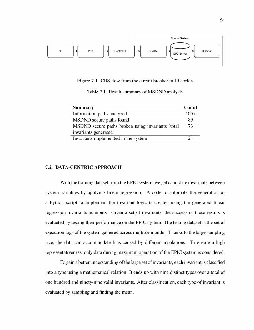
54
Figure 7.1. CBS flow from the circuit breaker to Historian
Table 7.1. Result summary of MSDND analysis
Summary CountInformation paths analyzed 100+MSDND secure paths found 89MSDND secure paths broken using invariants (totalinvariants generated)
73
Invariants implemented in the system 24
7.2. DATA-CENTRIC APPROACH
With the training dataset from the EPIC system, we get candidate invariants between
system variables by applying linear regression. A code to automate the generation of
a Python script to implement the invariant logic is created using the generated linear
regression invariants as inputs. Given a set of invariants, the success of these results is
evaluated by testing their performance on the EPIC system. The testing dataset is the set of
execution logs of the system gathered across multiple months. Thanks to the large sampling
size, the data can accommodate bias caused by different insolations. To ensure a high
representativeness, only data during maximum operation of the EPIC system is considered.
To gain a better understanding of the large set of invariants, each invariant is classified
into a type using a mathematical relation. It ends up with nine distinct types over a total of
one hundred and ninety-nine valid invariants. After classification, each type of invariant is
evaluated by sampling and finding the mean.

55
In real-time systems, the power variables will not strictly follow the invariant equa-
tions: there will be slight deviation from the actual relation. If the deviation value is less,
then the invariant is better. If an invariant with a higher deviation percentage is implemented
in the system, then it will raise false alarms. Consider an invariant relation involving two
variables P and Q given by the relation:
P = k ×Q
where k is a constant. Then, the relation involving deviation percentage and invariant is
given by the following equation:(100−deviation percentage
100 × P)≤ (k ×Q) ≤
(100+deviation percentage
100 × P)
The success rate of each invariant type is calculated for deviation percentages ±1% to
±6%. The success rate of an invariant for a particular deviation percentage is given by the
following relation:
Success rate = Number o f true alarms raised in an intervalTotal number o f alarms raised in an interval × 100 %
FromFigures 7.2 and 7.3, all nine types of invariants experiencemonotonic increases
on the success percentage as the deviation goes up. In another words, when releasing the
restriction on the percentage of deviation, more linear regression generated invariants tend
to be accepted by the power grid system. Type 1 to 8 all achieve a success rate high than
98.5%. However, the success rate given by Type 9 is among the 30s.
7.3. COMPARISON BETWEEN DeC AND DaC GENERATED INVARIANTS
The DeC invariants are generated by making use of SCADA and AMI variables,
but the DaC invariants are generated only using the SCADA variables, because of the issue
mentioned in Section 7.1. In the nine Stuxnet attacks that were modeled, the DeC invariants
can identify eight of them, as seen in the proofs. The DaC invariants generated without
AMI variables cannot identify any of the attacks, but if AMI variables are considered, then

56
Figure 7.2. Success rates of the invariants of type 1 to 8
it can identify one attack among the nine. This is because in DeC, there is a conjunction
present between two conditions, and we also consider Boolean states in this approach, which
makes it easier to identify the information path in which the fault/attack occurred. However,
because of the variety of system properties that were captured in DaC, these invariants
are much better in identifying faults that occur in the SCADA system when it is working
normally, and also in identifying uncorrelated attacks. For example, if an attacker changes
the line to line voltage of a particular relay, but did not change the line to neutral voltage,
the Type 2 DaC invariant would raise an alarm. A DeC invariant that uses both binary
(status) and numeric data is much better at identifying correlated attacks where the attacker
manages to corrupt all related variables with respect to a particular device. The comparison
between DeC and DaC generated invariants are summarized in the Table 7.2.

57
Figure 7.3. Success rate of the type 9 invariant
Table 7.2. Summary of DeC and DaC generated invariants
Summary CountStuxnet attacks modeled 9DeC invariants generated 73DaC invariants generated (without AMI variables) 199Attacks DeC invariants identify 8Attacks DaC invariants (without AMI variables) identify 0Attacks DaC invariants could identify (with AMI variables) 1

58
8. CONCLUSION
Vulnerable information paths were found in the EPIC testbed by MSDND analysis.
Over seventy-three invariants were created manually using the physics of the system. Some
of these invariants were implemented on the live system. Man-in-the-middle attacks were
launched, and on all instances they identified the attack and broke the MSDND secure path,
which is good for the system. Some invariants were also run on the data collected from
EPIC, which helped identify the problem in the logger of the EPIC system.
Over one hundred and fifty-two numeric variables in the SCADA system of the EPIC
testbed were analyzed using linear regression, and one hundred and ninety-nine invariants
were generated. Scripts were created to automate the generation of scripts to implement
the created invariants. The invariants were then categorized into nine types based on
the defined electrical equations and the efficiency of each type was analyzed for various
deviation percentages ranging from ±1% to ±6%, which is the allowed deviation in the
EPIC system.
The invariants generated through DeC and DaC approaches were compared for their
efficiency in identifying fault/attack, and it was found that the DeC invariants are better
in identifying correlated attacks and DaC invariants work better in identifying faults and
uncorrelated attacks in the system. DeC invariant generation heavily relies on the knowledge
of the system, and generating invariants for a large smart grid could be time-consuming.
To build a highly secure system, DeC would be the best approach to generate invariants
although it consumes more time. To identify faults arising in the system due to day-to-day
operation, DaC would be the best approach to generate invariants.

59
9. FUTURE WORK
The circuit breaker status was incorrect in the EPIC data that was collected by
Historian. To resolve this, a logger software can be created that directly retrieves live values
of the circuit breaker data from the OPC server and logs it into a CSV file. This would
eliminate the faulty status being recorded in the OPC server to Historian path. Using the
newly collected data, invariants can be generated using the association rule mining as done
by (Umer et al., 2017). Another direction would be to look into the possibility of merging
the linear regression and association rule mining generated invariants of the system on the
basis of a device.
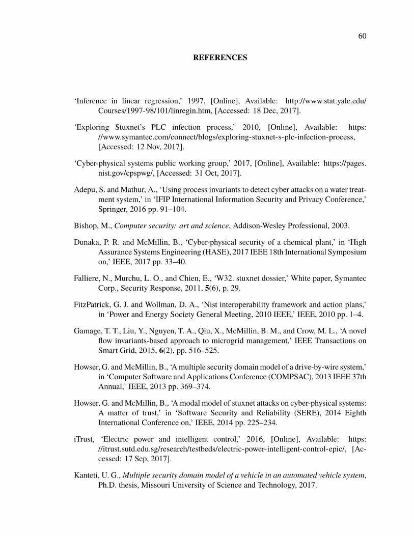
60
REFERENCES
‘Inference in linear regression,’ 1997, [Online], Available: http://www.stat.yale.edu/Courses/1997-98/101/linregin.htm, [Accessed: 18 Dec, 2017].
‘Exploring Stuxnet’s PLC infection process,’ 2010, [Online], Available: https://www.symantec.com/connect/blogs/exploring-stuxnet-s-plc-infection-process,[Accessed: 12 Nov, 2017].
‘Cyber-physical systems public working group,’ 2017, [Online], Available: https://pages.nist.gov/cpspwg/, [Accessed: 31 Oct, 2017].
Adepu, S. andMathur, A., ‘Using process invariants to detect cyber attacks on a water treat-ment system,’ in ‘IFIP International Information Security and Privacy Conference,’Springer, 2016 pp. 91–104.
Bishop, M., Computer security: art and science, Addison-Wesley Professional, 2003.
Dunaka, P. R. and McMillin, B., ‘Cyber-physical security of a chemical plant,’ in ‘HighAssurance Systems Engineering (HASE), 2017 IEEE 18th International Symposiumon,’ IEEE, 2017 pp. 33–40.
Falliere, N., Murchu, L. O., and Chien, E., ‘W32. stuxnet dossier,’ White paper, SymantecCorp., Security Response, 2011, 5(6), p. 29.
FitzPatrick, G. J. and Wollman, D. A., ‘Nist interoperability framework and action plans,’in ‘Power and Energy Society General Meeting, 2010 IEEE,’ IEEE, 2010 pp. 1–4.
Gamage, T. T., Liu, Y., Nguyen, T. A., Qiu, X., McMillin, B. M., and Crow, M. L., ‘A novelflow invariants-based approach to microgrid management,’ IEEE Transactions onSmart Grid, 2015, 6(2), pp. 516–525.
Howser, G. andMcMillin, B., ‘Amultiple security domainmodel of a drive-by-wire system,’in ‘Computer Software and Applications Conference (COMPSAC), 2013 IEEE 37thAnnual,’ IEEE, 2013 pp. 369–374.
Howser, G. andMcMillin, B., ‘A modal model of stuxnet attacks on cyber-physical systems:A matter of trust,’ in ‘Software Security and Reliability (SERE), 2014 EighthInternational Conference on,’ IEEE, 2014 pp. 225–234.
iTrust, ‘Electric power and intelligent control,’ 2016, [Online], Available: https://itrust.sutd.edu.sg/research/testbeds/electric-power-intelligent-control-epic/, [Ac-cessed: 17 Sep, 2017].
Kanteti, U. G.,Multiple security domain model of a vehicle in an automated vehicle system,Ph.D. thesis, Missouri University of Science and Technology, 2017.

61
Liau, C.-J., ‘Belief, information acquisition, and trust in multi-agent systemsâĂŤa modallogic formulation,’ Artificial Intelligence, 2003, 149(1), pp. 31–60.
Liau, C.-J., ‘A modal logic framework for multi-agent belief fusion,’ ACM Transactions onComputational Logic (TOCL), 2005, 6(1), pp. 124–174.
McMillin, B. and Roth, T., ‘Cyber-physical security and privacy in the electric smart grid,’Synthesis Lectures on Information Security, Privacy & Trust, 2017, 9(2), pp. 1–64.
Mueller, P. and Yadegari, B., ‘The stuxnet worm,’ 2012, [Online], Avail-able: https://www2.cs.arizona.edu/~collberg/Teaching/466-566/2012/Resources/presentations/2012/topic9-final/report.pdf, [Accessed: 18 Nov, 2017].
Owicki, S. and Gries, D., ‘An axiomatic proof technique for parallel programs i,’ Actainformatica, 1976, 6(4), pp. 319–340.
Paul, T., Kimball, J. W., Zawodniok, M., Roth, T. P., McMillin, B., and Chellappan, S.,‘Unified invariants for cyber-physical switched system stability,’ IEEE Transactionson Smart Grid, 2014, 5(1), pp. 112–120.
Roth, T. and McMillin, B., ‘Physical attestation in the smart grid for distributed stateverification,’ IEEE Transactions on Dependable and Secure Computing, 2016.
Sutherland, D., ‘A model of information,’ in ‘Proceedings of the 9th national computersecurity conference,’ volume 247, Washington, DC, 1986 pp. 175–183.
Thudimilla, A. and McMillin, B., ‘Multiple security domain nondeducibility air trafficsurveillance systems,’ in ‘High Assurance Systems Engineering (HASE), 2017IEEE 18th International Symposium on,’ IEEE, 2017 pp. 136–139.
Umer, M. A., Mathur, A., Junejo, K. N., and Adepu, S., ‘Integrating design and data centricapproaches to generate invariants for distributed attack detection,’ in ‘Proceedingsof the 2017 Workshop on Cyber-Physical Systems Security and PrivaCy,’ ACM,2017 pp. 131–136.

62
VITA
Prashanth Palaniswamy was born in Coimbatore, India. He received his Bachelor’s
degree in Computer Science and Engineering from Sri Ramakrishna Engineering College,
Coimbatore in May 2013. He then worked at Infosys Technologies, Mysore as a Senior
SystemsEngineer in the fields of software development and cloud computing. Afterworking
for three years he joined Missouri University of Science and Technology, USA in Aug 2016
to pursue Master’s degree in computer science. He joined Dr. Bruce McMillin’s research
group in Jan 2017 as a graduate research assistant in the field of cyber physical security
and enjoyed doing research under his guidance. He did Summer research internship at
the Singapore University of Technology and Design, Singapore under the guidance of Dr.
Aditya Mathur. In May 2018, he received his Master’s degree in Computer Science from
Missouri University of Science and Technology.