Cyber-Physical Engineering of - DiVA...
328
DOCTORAL THESIS Cyber-Physical Engineering of Distributed Automation Systems in Energy Domain Chen-Wei Yang Dependable Communication and Computation Systems
Transcript of Cyber-Physical Engineering of - DiVA...

DOCTORA L T H E S I S
Department of Computer Science, Electrical and Space EngineeringDivision of Computer Science
Cyber-Physical Engineering of Distributed Automation Systems in
Energy Domain
Chen-Wei Yang
ISSN 1402-1544ISBN 978-91-7790-076-4 (print)ISBN 978-91-7790-077-1 (pdf)
Luleå University of Technology 2018
Chen-W
ei Yang C
yber-Physical Engineering of D
istributed Autom
ation Systems in E
nergy Dom
ain
Dependable Communication and Computation Systems


Cyber-Physical Engineering ofDistributed Automation Systems in
The Energy Domain
Chen-Wei Yang
Dependable Communication and Computation SystemsDept. of Computer Science, Electrical and Space Engineering
Division of Computer ScienceLulea University of Technology
Lulea, Sweden
Supervisors:
Professor Valeriy Vyatkin, Professor Evgeny Osipov

Printed by Luleå University of Technology, Graphic Production 2018
ISSN 1402-1544 ISBN 978-91-7790-076-4 (print)ISBN 978-91-7790-077-1 (pdf)
Luleå 2018
www.ltu.se

To my families and friends who have been my pillars of support through thisjourney...
iii

iv

Abstract
The main focus of this thesis is in the domain of Energy Systems, specifically in the engi-neering of modern Smart Grid (SG) automation systems. The SG has been categorizedas a Cyber-Physical System (CPS), a complex system which exhibits tight integrationbetween the cyber and the physical processes and their interactions in a networked envi-ronment. The complexity and the computation of the automation system are expectedto increase with the promise of a ”smart” electric grid which is capable of self-healing,self-reconfiguration and become more resilient against cyber-attacks. These automationsoftware systems require control strategies which are distributed in execution and requirevery tight integrations and interactions between various modular software and hardwarecomponents. As the automation system becomes more software intensive, we hypothesizethat existing design practices of developing the substation automation software systemwould struggle to cope with the distributed design challenges of the Smart Grid and theycould be substantially enhanced by the application of model-driven design, distributedsoftware architectures and semantic models.
Model-driven engineering (MDE) is a software design paradigm that leverages the useof abstraction models at different stages of the design process for engineering complexsoftware systems. MDE is widely used in the software engineering domain and it hasproven to be effective when designing and maintaining large-scale software applications.One of the core tenants of MDE is model transformation and it is considered the heartand soul of MDE. The standard modelling language that is used for MDE in softwareengineering is the Unified Modelling Language (UML), which is a visual language with awide array of tool support. Despite its popularity in the software domain, UML modelsstill have its limitations. In particular, the lack of uniformed semantics between its 13different visual diagrams and the lack of formal notations. In this thesis, we proposethe Cyber-Physical Engineering (CPE) framework, an MDE framework which combinessemantic models and MDE based automatic model transformation in order to auto-generate both the automation control system and the simulation plant model from thephysical and functional specifications of CPS systems.
All the scientific papers included in this thesis contributes towards the proposedCyber-Physical Engineering methodology which includes MDE using semantic models,formal modelling of functional requirements and co-simulation testing of CPS systems.
The contribution of the thesis is fivefold. Firstly, the thesis proposes the CPE frame-work, which is based on the use of semantic web modelling language where logical rea-soning can be applied to the models. The modelling language that is used is the WebOntology Language (OWL), which is a declarative language with a strong formal foun-
v

dation based on description logic. Secondly, the extended Semantic Web Rule Language(eSWRL) is introduced which defines the constructors that are necessary for model trans-forming OWL ontology models. The eSWRL transformation language is proposed to bean extension to the widely used ontology reasoning language Semantic Web Rule Lan-guage (SWRL) in order to address the limitations of monotonicity which restricts SWRLfrom transforming ontological models. Thirdly, the implementation of the underlyingtransformation engine of eSWRL in SWI Prolog. Fourthly, the formal modelling of func-tional requirements in ontology is proposed which investigates the viability of using nat-ural language based functional requirements to add control flow to the auto-generatedautomation control system. Lastly, an automated script based co-simulation environ-ment is shown to demonstrate how black-box validation can be performed to test theauto-generated automation control system.
Finally, the thesis presents the resultant CPE framework for the modelling and genera-tion of distributed CPS automation software that leverages the use of semantic web OWLmodels. It is aimed to provide a top-down design approach of developing distributed con-trol software for CPS systems along with the simulation model of the physical plant. Inthis thesis, we demonstrate the development process of the CPE framework and throughcase study applications, how a semi-complete distributed automation software system inIEC 61499 can be automatically generated from substation specifications in IEC 61850and natural language based functional requirements which provide the structure and thecontrol flow of the distributed automation software respectively. An eSWRL toolchainhas been developed to facilitate the various model transformation process of the CPEframework.
vi

ContentsPart I 1
Chapter 1 – Thesis Introduction 31.1 Scope of the Thesis . . . . . . . . . . . . . . . . . . . . . . . . . . . . . . 61.2 Methodology . . . . . . . . . . . . . . . . . . . . . . . . . . . . . . . . . 71.3 Thesis Outline . . . . . . . . . . . . . . . . . . . . . . . . . . . . . . . . . 81.4 List of Abbreviations . . . . . . . . . . . . . . . . . . . . . . . . . . . . . 91.5 List of Related Publications Not Included in the Thesis . . . . . . . . . . 11
Chapter 2 – Smart Grid as a Cyber-Physical System 152.1 Transitioning Towards an Intelligent Electrical Grid . . . . . . . . . . . . 152.2 Distributed Infrastructure for the Smart Grid . . . . . . . . . . . . . . . 172.3 Distributed Intelligent Automation Systems for the Smart Grid . . . . . 192.4 The Smart Grid as a Cyber-Physical System . . . . . . . . . . . . . . . . 222.5 Harmonizing of Standards and Protocols for the Smart Grid . . . . . . . 232.6 Systems Engineering with IEC 61850 and IEC 61499 . . . . . . . . . . . 262.7 Chapter Summary . . . . . . . . . . . . . . . . . . . . . . . . . . . . . . 27
Chapter 3 – Systems Engineering 293.1 Systems Engineering Methodology . . . . . . . . . . . . . . . . . . . . . . 293.2 Systems Engineering in IEC 61850 . . . . . . . . . . . . . . . . . . . . . 323.3 Design Challenges of IEC 61850 Systems Engineering . . . . . . . . . . . 333.4 Synergies between IEC 61499 and IEC 61850 . . . . . . . . . . . . . . . . 353.5 Contribution of Paper A . . . . . . . . . . . . . . . . . . . . . . . . . . . 393.6 Discussion . . . . . . . . . . . . . . . . . . . . . . . . . . . . . . . . . . . 443.7 Enrichment of Semantics to IEC 61850 . . . . . . . . . . . . . . . . . . . 463.8 Chapter Summary . . . . . . . . . . . . . . . . . . . . . . . . . . . . . . 47
Chapter 4 – Cyber Physical Engineering 494.1 Cyber Physical Engineering Framework . . . . . . . . . . . . . . . . . . . 494.2 CPE Framework in the Energy Domain . . . . . . . . . . . . . . . . . . . 504.3 Ontology Driven MDE . . . . . . . . . . . . . . . . . . . . . . . . . . . . 534.4 eSWRL: Ontology Transformation Language . . . . . . . . . . . . . . . . 644.5 Chapter Summary . . . . . . . . . . . . . . . . . . . . . . . . . . . . . . 74
Chapter 5 – Requirements Modelling 775.1 Requirements Modelling in Natural Language . . . . . . . . . . . . . . . 775.2 Formal Modelling of Functional Requirements in Ontology . . . . . . . . 79
vii

5.3 Formalizing Natural Language Requirements to Ontology . . . . . . . . . 845.4 Implementation of BP Requirement with IEC 61850 LN Specifications . . 885.5 Chapter Summary . . . . . . . . . . . . . . . . . . . . . . . . . . . . . . 90
Chapter 6 – Testing and Validation 936.1 Validation of Functional Requirement . . . . . . . . . . . . . . . . . . . . 936.2 Automated Script based Co-Simulation Framework . . . . . . . . . . . . 946.3 Chapter Summary . . . . . . . . . . . . . . . . . . . . . . . . . . . . . . 96
Chapter 7 – Contributions 977.1 Paper A . . . . . . . . . . . . . . . . . . . . . . . . . . . . . . . . . . . . 977.2 Paper B . . . . . . . . . . . . . . . . . . . . . . . . . . . . . . . . . . . . 987.3 Paper C . . . . . . . . . . . . . . . . . . . . . . . . . . . . . . . . . . . . 987.4 Paper D . . . . . . . . . . . . . . . . . . . . . . . . . . . . . . . . . . . . 997.5 Paper E . . . . . . . . . . . . . . . . . . . . . . . . . . . . . . . . . . . . 1007.6 Paper F . . . . . . . . . . . . . . . . . . . . . . . . . . . . . . . . . . . . 1007.7 Paper G . . . . . . . . . . . . . . . . . . . . . . . . . . . . . . . . . . . . 1017.8 Paper H . . . . . . . . . . . . . . . . . . . . . . . . . . . . . . . . . . . . 1017.9 Paper I . . . . . . . . . . . . . . . . . . . . . . . . . . . . . . . . . . . . . 102
Chapter 8 – Conclusions and Future Work 1038.1 Conclusions . . . . . . . . . . . . . . . . . . . . . . . . . . . . . . . . . . 1038.2 Future Work . . . . . . . . . . . . . . . . . . . . . . . . . . . . . . . . . . 106
References 109
Part II 121
Paper A 1231 Introduction . . . . . . . . . . . . . . . . . . . . . . . . . . . . . . . . . . 1252 State-of-the-Art . . . . . . . . . . . . . . . . . . . . . . . . . . . . . . . . 1263 Power System Automation Design Process Based on IEC 61850 and MBSE 1274 SysGrid - Architecture and Capabilities . . . . . . . . . . . . . . . . . . . 1315 Case Study: Distributed Protection Application Design . . . . . . . . . . 1326 Conclusion . . . . . . . . . . . . . . . . . . . . . . . . . . . . . . . . . . . 139
Paper B 1431 Introduction . . . . . . . . . . . . . . . . . . . . . . . . . . . . . . . . . . 1452 Related Works . . . . . . . . . . . . . . . . . . . . . . . . . . . . . . . . . 1473 Novel Approach . . . . . . . . . . . . . . . . . . . . . . . . . . . . . . . . 1494 Case Study: Overcurrent Protection . . . . . . . . . . . . . . . . . . . . . 1505 Conclusion . . . . . . . . . . . . . . . . . . . . . . . . . . . . . . . . . . . 158
Paper C 1611 Introduction . . . . . . . . . . . . . . . . . . . . . . . . . . . . . . . . . . 163
viii
2 Related Works . . . . . . . . . . . . . . . . . . . . . . . . . . . . . . . . . 1643 Case Study: Sympathetic Trip . . . . . . . . . . . . . . . . . . . . . . . . 1654 Proposed Method . . . . . . . . . . . . . . . . . . . . . . . . . . . . . . . 1675 Conclusion . . . . . . . . . . . . . . . . . . . . . . . . . . . . . . . . . . . 174
Paper D 1771 Introduction . . . . . . . . . . . . . . . . . . . . . . . . . . . . . . . . . . 1792 State-of-the-Art . . . . . . . . . . . . . . . . . . . . . . . . . . . . . . . . 1823 Proposed Approach: eSWRL . . . . . . . . . . . . . . . . . . . . . . . . . 1854 Case Study . . . . . . . . . . . . . . . . . . . . . . . . . . . . . . . . . . 1905 Model Transformation . . . . . . . . . . . . . . . . . . . . . . . . . . . . 1926 Results . . . . . . . . . . . . . . . . . . . . . . . . . . . . . . . . . . . . . 1977 Conclusions and Future Work . . . . . . . . . . . . . . . . . . . . . . . . 201
Paper E 2071 Introduction . . . . . . . . . . . . . . . . . . . . . . . . . . . . . . . . . . 2092 Related Works . . . . . . . . . . . . . . . . . . . . . . . . . . . . . . . . . 2103 Ontology Model Transformation and Execution Semantics of eSWRL . . 2114 IEC 61850 Information Models . . . . . . . . . . . . . . . . . . . . . . . 2145 Case Study: eSWRL Model Transformation . . . . . . . . . . . . . . . . 2146 Conclusion . . . . . . . . . . . . . . . . . . . . . . . . . . . . . . . . . . . 221
Paper F 2251 Introduction . . . . . . . . . . . . . . . . . . . . . . . . . . . . . . . . . . 2272 Related Works . . . . . . . . . . . . . . . . . . . . . . . . . . . . . . . . . 2293 Requirement Modeling in Ontology . . . . . . . . . . . . . . . . . . . . . 2304 Case Study . . . . . . . . . . . . . . . . . . . . . . . . . . . . . . . . . . 2355 Conclusion . . . . . . . . . . . . . . . . . . . . . . . . . . . . . . . . . . . 243
Paper G 2471 Introduction . . . . . . . . . . . . . . . . . . . . . . . . . . . . . . . . . . 2492 Related Works . . . . . . . . . . . . . . . . . . . . . . . . . . . . . . . . . 2513 Design Methodology . . . . . . . . . . . . . . . . . . . . . . . . . . . . . 2524 Case Study . . . . . . . . . . . . . . . . . . . . . . . . . . . . . . . . . . 2535 Modeling IEC 61850 Services in IEC 61499 . . . . . . . . . . . . . . . . . 2546 Conclusion . . . . . . . . . . . . . . . . . . . . . . . . . . . . . . . . . . . 264
Paper H 2671 Introduction . . . . . . . . . . . . . . . . . . . . . . . . . . . . . . . . . . 2692 Related Works . . . . . . . . . . . . . . . . . . . . . . . . . . . . . . . . . 2723 Proposed Methodology . . . . . . . . . . . . . . . . . . . . . . . . . . . . 2744 Case Study . . . . . . . . . . . . . . . . . . . . . . . . . . . . . . . . . . 2805 Conclusion and Future Work . . . . . . . . . . . . . . . . . . . . . . . . . 285
Paper I 2911 Introduction . . . . . . . . . . . . . . . . . . . . . . . . . . . . . . . . . . 293
ix

2 Electrical System and Protection . . . . . . . . . . . . . . . . . . . . . . 2963 Fault Location and Isolation . . . . . . . . . . . . . . . . . . . . . . . . . 2974 Analysis of the FLI Algorithm . . . . . . . . . . . . . . . . . . . . . . . . 2995 Simulation . . . . . . . . . . . . . . . . . . . . . . . . . . . . . . . . . . . 3026 Numerical Results . . . . . . . . . . . . . . . . . . . . . . . . . . . . . . . 3077 Conclusion . . . . . . . . . . . . . . . . . . . . . . . . . . . . . . . . . . . 307
x

Acknowledgments
It was almost 5 years ago when I embarked on my journey towards a PhD degree. I leftthe comfort of New Zealand 5 years ago and literally flew to the opposite side of the globeto this little unknown place (well, it was unknown to me at the time) called Lulea whichwill now always have a place in my heart. The road hasn’t always been smooth but thepersonal and professional experiences I have gained along the way has been nothing butinvaluable to me. Along this journey, I was fortunate to have participated in internationalprojects, travelled around the world to take part in conferences and projects and havemet many interesting and inspiring people in and out of the workplace who have providedme with encouragement and support which I am eternally thankful for. I would like todedicate this milestone to all who have supported me along this journey.
I don’t have enough words to express my gratitude to my main supervisor ProfessorValeriy Vyatkin. Professor Vyatkin was my supervisor during my Masters of Researchstudies at the University of Auckland and I can’t thank him enough for giving me theopportunity to come to Sweden to pursue my PhD. His invaluable support, professionaladvice, patience and encouragement has been the motivational voice that has pushedme through the darkest times of my PhD studies. I would also like to thank my co-supervisor Professor Evgeny Osipov and visiting Associate Professor Victor Dubinin fortheir support and professional advice during my PhD studies.
I would like to express my gratitude to my fellow PhD colleagues Denis Kleyko andSandeep Patil. We all embarked on this journey almost 5 years ago and I think it’spoetic (well, to me at least) that we will all finish at the same time. I also like to thankDr Gulnara Zhabelova, who has been a valuable senior research colleague to me sincemy Masters studies and she is someone who I have always been able to turn to whenI had difficulties in my research. Two senior colleagues whom I would like to expressmy gratitude for are Associate Professor William Dai and Dr Cheng Pang who continueto provide me with professional advice and got me through my first year here in Lulea.Those weekly ”make-do-since-we-have-no-other-choice” hotpot during the dark wintershave left a taste in my mouth which will stay with me forever.
My eternal love and gratitude to my parents XiaoMin, ChuanChang and my dearestyounger sister Sabina for their continuous support for the past 5 years, especially sinceI left NZ on such a short notice. I am fortunate to be able to visit NZ once a year,but I know it is not enough. It is one of the toughest sacrifices I have had to makeon this journey and it does not get easier by the day. The experiences I have gatheredboth professionally and personally in the past 5 years have shaped me to who I amtoday and I am forever indebted to my parents for giving me the opportunities and the
xi

encouragement to explore my own interests and seek my own destiny in life.My gratitude also goes to Anabelle, Johan, Eva-Lena, Karin, Fredrik and little Benji
who have been like a second family to me in Sweden. I can’t express enough gratitude forall the family events which you have invited me to. You all have given me opportunitiesto experience so many facets of Swedish culture which I will be forever grateful.
I would also like to thank Bertie and the Lulea Toastmasters club. This crazy idea ofchartering a Toastmasters club came during a casual conversation on a sunny afternoonat the end of our SFI introduction class. 4 years later, our club has the distinction ofbeing the northernmost Toastmasters club in the world and I couldn’t have been moreproud of the countless hours of volunteering work that everyone on the Toastmastercommittee has done to charter the club. Toastmasters has provided me with so muchvaluable experiences and I will always value the platform Toastmasters has given me tobecome a better speaker.
Honourable mentions to my friends Charlene, Mhaine, Mats and Lycka. Those snowfights in Sodra Hamn and hiking trips to Storforsen and Stora Sjofallet will always bememorable to me. The same goes for all my friends back in NZ and the UK who havealways met me without hesitation to catch-up even though it’s always on short notice!
April 2018, Lulea, SwedenChen-Wei Yang
xii

Part I
1

2

Chapter 1
Thesis Introduction
Shortly after 4 P.M Eastern Daylight Time on August 14, 2003, the largest blackoutin North America history took place where more than 50 million people lost power for upto two days [1] which had an economic cost of approximately 4 to 6 billion dollars for theaffected regions. According to the final report on the August 2003 blackout publishedby the US-Canada Power System Outage Task Force [2], errors in the software systemscontributed to the devastating blackout that affected much of the North-eastern andMid-western part of the US and the southern part of Canada in 2003. The initial faulttook place at 2 P.M when one of the high voltage power lines in north Ohio sagged underthe high heat and consequently, brushed against overgrown trees and switched off. Thisinitial fault was undetected due to:
1. Firstly, a faulty state estimator which was not turned back on after troubleshooting.The role of the state estimator is to estimate the real and reactive power flow onthe lines and transformers in their transmission facilities based on the real-timedata it receives at regular intervals. The state estimator was not turned on aftertroubleshooting [2].
2. Secondly, the logging software which collects real-time data from the Remote Termi-nal Units (RTU) malfunctioned and was not able to provide data on the operatingstate of the transmission facilities. This was because the real-time data comingfrom the RTUs to the Energy Management System (EMS) started to build-up andeventually, overflowed the input buffers [2].
3. Lastly, the alarm system which is typically used to alert system faults to gridoperators by means of audio or visual signals were not functional.
The failure of the software systems in the EMS and the automation system meant thegrid operators were not informed of the deteriorating conditions of the electrical systemand therefore, preventative measures could not be taken to prevent the resultant black-out. Unplanned outages in the electrical network can be catastrophic and automationsoftware systems are deployed in substations in order to continuously monitor, control
3
4 Thesis Introduction
and protect the grid by the aid of Supervisory Control and Data Acquisition (SCADA)systems. Substations are nodes in the electrical grid which transform and route the en-ergy throughout the electrical grid and usually contains Substation Automation Systems(SAS) which are either manned or unmanned depending on the importance of the sub-station [3]. The role of the SAS is to monitor, meter, protect and control the substation[4]. The core components of a SAS system are the local intelligence, the data communica-tion and the supervisory control and monitoring. The local intelligence, or the Protectionand Control (PAC) functionalities are typically operating in Intelligent Electronic Devices(IED) devices in a networked environment. The IEDs serve as the ”intelligent nodes” ofthe electrical grid which serves to monitor the voltage and the current, interrupt faultcurrents, communicate messages between IED devices and to perform reconfiguration tosatisfy the need of the customers or other objectives [5]. All these functionalities areperformed automatically by the automation system and the automation system is anintegral component of the current substation infrastructure.
The Smart Grid is positioned as the natural evolution of the electrical grid which isdriven is driven by the integration of Information and Communication Technologies (ICT)and the increase in adoption of Distributed Renewable Energy Resources (DRER). Theaim of the Smart Grid vision is to bring the existing electricity generation, delivery anddistribution infrastructure into the 21st century by incorporating advanced computer-based control and automation systems along with advanced measurement capabilitiesand standards. The electric grid will become ”smart” with the availability of real-timedata providing more granular point of decision making for PAC systems. The currentpower delivery process is largely unidirectional and is typically managed by centralizedcontrol systems. However, with a mass integration of DRER devices, the generationof electricity will be dispersed with renewable resources such as wind/solar farms orhydro plants rather than bulk generation from a singular source. This dispersion ingeneration is magnified even more if you take into consideration the DRER sources atthe residential level, the overall infrastructure of the electrical grid becomes even moredistributed. The flow of energy is now bi-directional where the consumers can nowconsume and generate power back to the grid. This distribution in infrastructure doesn’thappen just at the physical infrastructure level, it also introduces design challenges to theprotection and control (PAC) system as the automation system of the Smart Grid is onlyexpected to increase with the emphasis on self-healing, self-reconfiguration, resilienceagainst cyber-attacks and load-management/demand-response applications, etc. Theseautomation control systems require control strategies which are distributed in executionand require very tight integrations and interactions between various modular softwareand hardware components. The automation system is foreseen as an integral componentof the Smart Grid infrastructure that is expected to be able to handle the expectedincrease in computation that is required by the distributed control strategies.
However, the question needs to be raised of whether the existing substation automa-tion infrastructure can meet the expectation that is placed on the automation systems. Inreality, only approximately 5% of the 42000 secondary substations operated by Vattenfallin Sweden have some degree of automation and only 1000 or so primary substations are

5
fully automated [6]. In fact, a large portion of the substation automation systems inmany countries are more than 30 years old and are still running electromechanical relaysand analogue RTUs which have not been installed for more than two decades [6] andlacks the communication capabilities that are required in modern PAC systems. Theageing of the automation systems is compounded by the fact that due to the varying rateof the refurbishment of the automation system, substations are essentially running het-erogenous automation systems with varying degrees of age in technology and each with adifferent refurbishment life cycle. The existing automation infrastructure would struggleto handle the increase in computation that is required from the automation system andthere is also the need to automate existing secondary substations which are un-monitoredand un-automated.
A change in the paradigm of the control system also inspires an investigation ofhow the systems engineering approach to engineering substations could be improved toaccommodate the distributed architecture and improve the flexibility of the design pro-cess. The current design approach of substation engineering is very much a bottom-updesign approach and it is typically used to design PAC management systems that aremore compatible with existing SCADA communications network architectures, whichhave been designed to support centralized monitoring and control. For systems whichare distributed in design, it is more effective to employ top-down design approach whichendorses the design of the global behaviour of the system in the first step of the designprocess before the implementation in hardware controllers. This way, there is a clearoverview of all the required functionalities and the interactions of the functional compo-nents within the system. In the current state where the implementation of functionalitiesis largely dictated by hardware vendors, the design process is extremely inflexible sinceall the functionalities within the hardware are fixed and this adds an unnecessary limita-tion to the system integrators. This means there is very little space for flexibility in thedesign of the automation system and this also affects the scalability of the system whereit is very difficult to add or modify additional PAC functionalities without changing thehardware. Having the freedom to choose functionalities from different vendors which canrun on the same integrated devices would allow a lot more flexibility and scalability in thedesign of the automation system. Ideally, the design of the substation automation systemshould be driven by the technical requirements for the system based on the need for theprotection and the control philosophy. Unfortunately, as often the case, PAC systemsare designed around the limitations of the chosen or the installed equipment. Vatten-fall Sweden had, in fact, investigated the concept of ”soft protection & control” [7], anopen-platform where PAC functionalities are implemented as software modules that arerunning on an industrial PC connected to I/Os via a communication bus. Another ex-ample of a vendor-independent solution is presented in [8] where protection functions forrailroads are implemented in Programmable Logic Controllers (PLC) where protectionfunctions can be developed and further improved independently from the hardware thatit’s running on. This is a totally different approach from the status quo in substationautomation where purchasing the PAC functions also means purchasing the hardware.
We hypothesise that existing design practices of developing the substation automation

6 Thesis Introduction
software system would struggle to cope with the distributed design challenges of theSmart Grid and they could be substantially enhanced by the application of model-drivendesign, distributed software architectures and semantic models. The aim of this thesis isto propose a top-down design framework for the design of substation automation softwarein Smart Grids which adopts the model-driven software design techniques that leveragethe use of knowledge models.
The proposed framework is called The Cyber-Physical Engineering (CPE) frameworkwhich consists of 4 core components. The first is the substation automation standardIEC 61850, which defines the physical and functional specification of the substationand the configurations of the communication network and the hardware devices. Thesecond component is the IEC 61499 standard, which is the reference architecture forthe design of distributed industrial automation systems. IEC 61499 introduces genericmodelling artefacts for the design of distributed systems with the aim of portability,reusability, interoperability and reconfiguration of distributed applications. The thirdcomponent is the semantic model represented as ontologies, which introduce vocabulariesthat formally specifies the conceptualization of the domain. I.e. a formal description ofthe logic structure of the domain through concepts and its relations. The last componentis model transformation, an automated process in Model-Driven Engineering (MDE) thattransforms source models to target models through the use of transformation rules.
The research work in this thesis was conducted to address the following research ques-tions:
Q1: To what extent can a distributed substation automation software system be auto-matically generated with MDE techniques by leveraging the industrial standardsIEC 61850 and IEC 61499? What is missing and what more is needed to automat-ically generate a software automation system that complies with top-down designapproaches?
Q2: What are the fundamental principles behind a possible MDE automatic generationframework that leverage the use of knowledge bases such as ontological models?
Q3: To what extent can formal modelling of functional requirements assists in automat-ically generating an IEC 61499 automation software system with control flow?
Q4: How the compliance of the generated system with the requirements could be effi-ciently and rigorously validated?
1.1 Scope of the Thesis
This thesis focuses on the development of a CPS framework with software-intensive in-dustrial automation systems in the energy domain. The emphasis is on the engineering ofautomation systems which are distributed and can be designed in a vendor-independentway. The framework adopts MDE methodologies that leverage the use of semantic models

1.2. Methodology 7
to automatically generate automation software from the physical and cyber specificationof the system. The scope of the framework is restricted to the development of the ontologytransformation language, the ontology transformation engine and the auto-generation ofthe distributed automation control system from system specifications.
1.2 Methodology
The work in this thesis is divided into 4 stages, 1 stage for each research question. Thefirst stage is the initial investigation of the extent in which a distributed automationsystem in IEC 61499 can be automatically generated based on IEC 61850 specifications.Paper A shows the top-down design synergies of the two industrial standards and themissing components that need to be addressed in order to auto-generate a full distributedautomation system model, paper A contributes to addressing research question 1.
The second stage is to investigate the potential of utilizing a declarative-based modeltransformation language to model transform ontologies. The early prototyping of thedeclarative ontology model transformation language called extended Semantic Web RuleLanguage (eSWRL) is shown in Paper B, a graph and ontology-based model of messagepassing to model the control of the software system was developed in Paper C and thecomplete development of the model transformation framework for transforming onto-logical models using the eSWRL transformation language is discussed in paper D. Theresults from paper E extend the work further by discussing the execution model of thetransformation language. These papers contribute towards addressing research question2.
The third stage is to investigate the extent to which functional requirements can beused to model control flow in the auto-generated IEC 61499 automation control systemto address one of the limitations identified in stage 1. Functional requirements typicallydescribe a certain functional behaviour in the control system and we hypothesis that itcan be formalized and used to prescribe the control flow of the FB network. Exploratorysteps in paper F and paper G show how functional requirements can be used to fill themissing semantic component. Paper H extends the results of paper F and paper G toformally model the functional requirements in boilerplates and ontology. In addition,the paper H illustrates how the formal requirement models can be incorporated into theontology-based MDE framework. These set of papers contribute to addressing researchquestion 3.
The fourth stage is to investigate how the functional requirements can be verifiedin the end IEC 61499 software automation control system. The verification techniqueis based on black box testing, which is a testing technique that is commonly employedto test the software system meets the initial functional requirements. The approachpresented in paper I is a script based black-box testing of the distributed automationcontrol system in a co-simulation environment.
An illustration of the relationship of the papers and their contribution to each stageof the research is shown in Figure 1.1. The dashed arrows show the progression orderbetween the research papers. Paper A contributes to Stage 1. Paper B, C, D and E

8 Thesis Introduction
contribute to stage 2. Paper F, G and H contribute to stage 3 and paper I contribute tostage 4. The in-depth contribution of each paper is discussed in more detail in chapter7.
Figure 1.1: Visual representation showing the contribution of the papers to each stage of researchand the progression of papers.
1.3 Thesis Outline
This thesis is separated into two parts. Part 1 provides the comprehensive summaryof the research work and it consists of 8 chapters. Part 2 contains two published andpeer-reviewed IEEE Transactions papers, one submitted IEEE Transactions paper, onepublished and peer-reviewed open access EAI endorsed Transactions paper and five pub-lished and peer-reviewed IEEE international conference papers.
The chapter breakdown of part 1 is as follows. Chapter 1 provides the background andformulates the research questions on which this thesis is based on. Chapter 2 discussesthe advent of the Smart Grid and its design challenges introduced from the perspectiveof Cyber-Physical Systems. Chapter 3 discusses the synergies of the IEC 61850 andIEC 61499 in terms of systems engineering (top-down design approach) and identifiesthe semantic gap and the systems engineering gap that exist in the IEC 61850 standard.Chapter 4 introduces the Cyber-Physical Engineering framework and the development ofthe eSWRL ontology transformation languages and the ontology transformation engine.
1.4. List of Abbreviations 9
Chapter 5 investigates the formal modelling of system requirements and how systemrequirements can be used to prescribe control flow in IEC 61499 automation controlsystem. Chapter 6 investigates how co-simulation can be used to verify the correctnessof the global behaviour of the automatically generated IEC 61499 automation controlsystem by means of script testing. Chapter 7 outlines the contributions of the researchpapers in part 2. Lastly, chapter 8 provides the conclusions of the thesis and addressesthe research questions from chapter 1.
1.4 List of Abbreviations
A-Box: Assertion BoxBP: Boilerplate
CID: Configured IED Description
CIM: Common Information Model
CPE: Cyber-Physical Engineering
CPS: Cyber-Physical System
CWA: Closed World Assumption
DA: Data Attribute
DAType: Data Attribute Type
DESD: Distributed Energy Storage Devices
DGI: Distributed Grid Intelligence
DLP: Description Logic Program
DMS: Distribution Mangagement System
DNM: Domain Neutral Models
DO: Data Object
DOType: Data Object Type
DRER: Distributed Renewable Energy Resources
DSM: Domain Specific Models
DTD: Document Type Definition
ECC: Execution Control Chart
EMS: Energy Mangagement System
eSWRL: extended Semantic Web Rule Language
FB: Function Block
FBType: Function Block Type

10 Thesis Introduction
FLI: Fault Location and Isolation
FLISR: Fault Location, Isolation and Service Restoration
FREEDM: Future Renewable Electric Energy Delivery and Management
HMI: Human Machine Interface
ICD: IED Capability Description
ICT: Information and Communication Technologies
IDE: Integrated Development Environment
IED: Intelligent Electronic Devices
IEM: Intelligent Energy Management
IFM: Intelligent Fault Management
IID: Instantiated IED Description
LN: Logical Node
LNodeType: Logical Node Type
MAS: Multi Agent Systems
MDA: Model Driven Architecture
MDE: Model Driven Engineering
NIST: National Institute of Standards and Technology
NL: Natural Language
OMG: Object Management Group
OWA: Open World Assumption
OWL: Web Ontology Language
PAC: Protection and Control
RNL: Restricted Natural Language
RTU: Remote Terminal Unit
SAS: Substation Automation Systems
SCADA: Supervisory Control and Data Acquisition
SCD: System Configuration Description
SCL: Substation Configuration Language
SED: System Exchange Description
SG: Smart Grid
SGAM: Smart Grid Architecture Model
1.5. List of Related Publications Not Included in the Thesis 11
SLD: Single Line Diagram
SOA: Service Oriented Architecture
SSD: System Specification Description
SWRL: Semantic Web Rule Language
T-Box: Terminology Box
UDP: User Datagram Protocol
UML: Unified Modelling Language
XML: Extensible Markup Language
1.5 List of Related Publications Not Included in the
Thesis
[1] A. Voinov, C.-W. Yang, and V. Vyatkin, ”Automatic generation of function block sys-tems implementing HMI for energy distribution automation,” in Industrial Informatics(INDIN), 2017 IEEE 15th International Conference on, 2017, pp. 706-713.
[2] C.-W. Yang, V. Vyatkin, and V. Dubinin, ”Automatic generation of cyber-Physicalsoftware applications based on physical to cyber transformation using ontologies,” in Doc-toral Conference on Computing, Electrical and Industrial Systems, 2016, pp. 37-45.
[3] G. Zhabelova, C. Yang, V. Vyatkin, N. Etherden, and L. Christoffersson, ”Open ar-chitecture for cost effective protection and control of power distribution networks,” inSmart Grid Communications (SmartGridComm), 2016 IEEE International Conferenceon, 2016, pp. 729-735.
[4] C.-W. Yang, E. Nefedov, S. Sierla, and P. Flikkema, ”Vehicle and pedestrian awarestreet lighting automation,” in Industrial Informatics (INDIN), 2015 IEEE 13th Interna-tional Conference on, 2015, pp. 1269-1274.
[5] K. Gulzar, S. Sierla, V. Vyatkin, N. Papakonstantinou, P. G. Flikkema, and C.-W.Yang, ”An auction-based smart district heating grid,” in Emerging Technologies & Fac-tory Automation (ETFA), 2015 IEEE 20th Conference on, 2015, pp. 1-8.
[6] C.-W. Yang, K. Gulzar, S. Sierla, and V. Vyatkin, ”Fuzzy Logic Based Prosumer Agentin a Modular Smart Grid Prosumer Architecture,” in Trustcom/BigDataSE/ISPA, 2015IEEE, 2015, vol. 3, pp. 261-268.
[7] C. Pang, S. Patil, C.-W. Yang, V. Vyatkin, and A. Shalyto, ”A portability study ofIEC 61499: Semantics and tools,” in Industrial Informatics (INDIN), 2014 12th IEEEInternational Conference on, 2014, pp. 440-445.
[8] E. Vesaoja, H. Nikula, S. Sierla, T. Karhela, P. G. Flikkema, and C.-W. Yang, ”Hybrid

12 Thesis Introduction
modeling and co-simulation of district heating systems with distributed energy resources,”in Modeling and Simulation of Cyber-Physical Energy Systems (MSCPES), 2014 Work-shop on, 2014, pp. 1-6.
[9] E. Nefedov et al., ”Energy efficient traffic-based street lighting automation,” in Indus-trial Electronics (ISIE), 2014 IEEE 23rd International Symposium on, 2014, pp. 1718-1723.
[10] R. Baniya, M. Maksimainen, S. Sierla, C. Pang, C.-W. Yang, and V. Vyatkin, ”Smartindoor lighting control: Power, illuminance, and colour quality,” in Industrial Electronics(ISIE), 2014 IEEE 23rd International Symposium on, 2014, pp. 1745-1750.
[11] S. Sierla, M. Hurkala, K. Charitoudi, C.-W. Yang, and V. Vyatkin, ”Security riskanalysis for smart grid automation,” in Industrial Electronics (ISIE), 2014 IEEE 23rdInternational Symposium on, 2014, pp. 1737-1744.
[12] G. Zhabelova et al., ”Cyber-physical components for heterogeneous modelling, valida-tion and implementation of smart grid intelligence,” in Industrial Informatics (INDIN),2014 12th IEEE International Conference on, 2014, pp. 411-417.
[13] H. Nikula et al., ”Co-simulation of a dynamic process simulator and an event-basedcontrol system: Case district heating system,” in Emerging Technology and Factory Au-tomation (ETFA), 2014 IEEE, 2014, pp. 1-7.
[14] V. Dubinin, V. Vyatkin, C.-W. Yang, and C. Pang, ”Automatic generation of au-tomation applications based on ontology transformations,” in Emerging Technology andFactory Automation (ETFA), 2014 IEEE, 2014, pp. 1-4.
[15] J. Yan, C. Pang, C.-W. Yang, and V. Vyatkin, ”Adaptable software components: To-wards digital ecosystems and software evolution in the industrial automation domain,” inIndustrial Electronics Society, IECON 2014-40th Annual Conference of the IEEE, 2014,pp. 2512-2518.
[16] C.-W. Yang, J. Xu, and V. Vyatkin, ”Towards implementation of IEC 61850 GOOSEmessaging in event-driven IEC 61499 environment,” in Emerging Technology and Fac-tory Automation (ETFA), 2014 IEEE, 2014, pp. 1-4.
[17] C. Yang, G. Zhabelova, C.-W. Yang, and V. Vyatkin, ”Cosimulation environmentfor event-driven distributed controls of smart grid,” IEEE Trans. Ind. Informatics, vol.9, no. 3, pp. 1423-1435, 2013.
[18] G. Zhabelova, S. Patil, C. Yang, and V. Vyatkin, ”Smart Grid applications withIEC 61499 reference architecture,” in Industrial Informatics (INDIN), 2013 11th IEEEInternational Conference on, 2013, pp. 458-463.
[19] J. Xu, C.-W. Yang, G. Zhabelova, S. Berber, and V. Vyatkin, ”Towards imple-mentation of IEC 61850 GOOSE messaging in IEC 61499 environment,” in IndustrialInformatics (INDIN), 2013 11th IEEE International Conference on, 2013, pp. 464-470.
[20] G. Zhabelova, C.-W. Yang, and V. Vyatkin, ”SysGrid: IEC 61850/IEC 61499 basedengineering process for Smart Grid automation design,” in Industrial Informatics (IN-

1.5. List of Related Publications Not Included in the Thesis 13
DIN), 2013 11th IEEE International Conference on, 2013, pp. 364-369.
[21] J. Yan, C. Pang, C.-W. Yang, and V. Vyatkin, ”Towards automated visualization fordistributed automation applications,” in Emerging Technologies & Factory Automation(ETFA), 2013 IEEE 18th Conference on, 2013, pp. 1-4.
[22] C.-W. Yang, J. Yan, and V. Vyatkin, ”Towards implementation of Plug-and-Playand distributed HMI for the FREEDM system with IEC 61499,” in Industrial Electron-ics Society, IECON 2013-39th Annual Conference of the IEEE, 2013, pp. 5347-5353.

14 Thesis Introduction

Chapter 2
Smart Grid as a Cyber-PhysicalSystem
This chapter presents the evolution of the electrical grid towards the so-called SmartGrid. The Smart Grid is presented from the perspective of a Cyber-Physical Systemto highlight the change of the electrical grid from a centralized system to a distributedsystem, both in its physical and cyber aspects. The aim is to give an overview of thechallenges that are introduced by the advent of a the Smart Grid that motives theundertaking of the research in this thesis.
2.1 Transitioning Towards an Intelligent Electrical
Grid
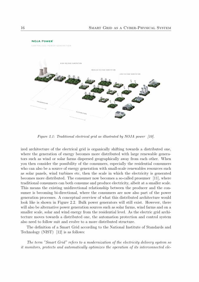
The electrical grid is a complex producer and consumer system which generates, transmitsand distributes electricity [9]. An overview of the traditional electrical grid is shown inFigure 2.1. The electricity is first generated in bulk in facilities such as nuclear powerplants, coal or gas burning plants or hydro plants, etc. The generated electricity is thenstepped up to a higher voltage before it is transmitted via transmission lines over longdistances to the substations for distribution. Finally, the high voltage is stepped down atvarious substations to a lower voltage before it is distributed to industrial and residentialconsumers etc. This is a unidirectional process where the producer generates the bulkof the electricity and the consumers consume the generated electricity. This architectureis considered to be a centralized architecture and it is often referred to as centralizedgeneration.
With the rapid advancement of Information and Communications Technology (ICT)technologies and the integration of ICT technologies in the current electric grid, the tra-ditional grid is becoming ”smart” with the availability of real-time information enablingsmarter decision making for control and protection purposes. In addition, the uptake inthe adoption of renewable energy resources in Europe means that the traditional central-
15
16 Smart Grid as a Cyber-Physical System
Figure 2.1: Traditional electrical grid as illustrated by NOJA power [10].
ized architecture of the electrical grid is organically shifting towards a distributed one,where the generation of energy becomes more distributed with large renewable genera-tors such as wind or solar farms dispersed geographically away from each other. Whenyou then consider the possibility of the consumers, especially the residential consumerswho can also be a source of energy generation with small-scale renewables resources suchas solar panels, wind turbines etc, then the scale in which the electricity is generatedbecomes more distributed. The consumer now becomes a so-called prosumer [11], wheretraditional consumers can both consume and produce electricity, albeit at a smaller scale.This means the existing unidirectional relationship between the producer and the con-sumer is becoming bi-directional, where the consumers are now also part of the powergeneration processes. A conceptual overview of what this distributed architecture wouldlook like is shown in Figure 2.2. Bulk power generators will still exist. However, therewill also be alternative power generation sources such as solar farms, wind farms and on asmaller scale, solar and wind energy from the residential level. As the electric grid archi-tecture moves towards a distributed one, the automation protection and control systemalso need to follow suit and evolve to a more distributed structure.
The definition of a Smart Grid according to the National Institute of Standards andTechnology (NIST) [12] is as follows:
The term ”Smart Grid” refers to a modernization of the electricity delivery system soit monitors, protects and automatically optimizes the operation of its interconnected ele-

2.2. Distributed Infrastructure for the Smart Grid 17
Figure 2.2: Conceptual model of the Smart Grid as illustrated by NOJA power [10].
ments - from the central and distributed generator through the high-voltage transmissionnetwork and the distribution system, to industrial users and building automation systems,to energy storage installations and to end-use consumers and their thermostats, electricvehicles, appliances and other household devices. The Smart Grid will be characterized bya two-way flow of electricity and information to create an automated, widely distributedenergy delivery network. It incorporates into the grid the benefits of distributed computingand communications to deliver real-time information and enable the near-instantaneousbalance of supply and demand at the device level.
By this definition, the Smart Grid is said to be a system which will become moredistributed in both its physical and logical infrastructures. The change to a distributedinfrastructure is driven by the increase in the adaptation of modular DRERs [13] such assolar panels or wind turbines and Distributed Energy Storage Devices (DESD) [13] suchas batteries or hydrogen storages. In fact, the European Commission has set a target ofraising the usage of renewable in their energy usage to 20% by 2020 [14] as part of the”20-20-20” EU Climate and Energy Package, while similar directives have also been set inthe US of achieving 20% renewables in overall power usage by 2020 [15]. This dispersionin generation is magnified even more if you take into consideration the DRER sources atthe residential level, the overall infrastructure of the electrical grid becomes even moredecentralized and dispersed. This will have a profound impact on the energy flow of thegrid where the energy flow will become bidirectional rather than unidirectional.
2.2 Distributed Infrastructure for the Smart Grid
The Future Renewable Electric Energy Delivery and Management (FREEDM) systemis one theorized infrastructural model for the Smart Grid and it is often referred to asthe ”Energy Internet” [13]. The FREEDM system is envisioned to function much likethe client-based internet infrastructure (A client-based computing infrastructure which

18 Smart Grid as a Cyber-Physical System
connects users globally in a networked environment [16]) that is adopted by the computerindustry. The FREEDM system provides many research challenges in both the physicaland the cyber aspect of system design that needs to be addressed. The three enablingtechnologies which are necessary to make the envisioned Energy Internet infrastructurea reality is:
1. A plug-and-place interface which consists of a 400-V bus direct current (DC) busand a 120-V alternating (AC) bus. Accompanied by an open-standard communi-cation interface which allows the FREEDM grid to automatically recognize andconfigure devices such as loads, DESD devices, and DRER devices when it is cou-pled to the FREEDM grid. The plug-and-play interface is analogous to the conceptof Universal Serial Bus (USB) port of computers and is envisioned to work in thesame way [13].
2. The so-called ”Energy router” which manages the DESD and the DRER devicesthat are connected to the FREEDM grid. The function of the energy router includesmonitoring, controlling and regulating the DESD and DRER devices. The role ofthe energy router is fulfilled by the Solid State Transformer (SST) [17], a powerelectronic device that connects to the 12-kV AC distribution bus and the 120V ACand 400V dc buses [13]. A visual representation of this conceptual plug-and-playstructure is shown in Figure 2.3 which highlights the SSTs as the hub in whichconnects the AC and the DC bus to the grid.
3. An open-standard operating system, or the Distributed Grid Intelligence (DGI) asit is called [13] is distributed across all the IEM devices and tasked with the respon-sibility of coordinating and managing the IED devices distributed across the com-munication network. Both the Energy Router and the DGI operating system arepart of the Intelligent Energy Management (IEM) system of the FREEDM infras-tructure. These two management systems are part of cyber part of the FREEDMsystem infrastructure and these management systems consist of modular cyber unitsthat operate throughout the FREEDM system as shown in Figure 2.4.
The conceptual FREEDM architectures in Figure 2.3 and Figure 2.4 shows that inorder to transition to an infrastructure of power delivery which is distributed, thereneeds to be a complimentary cyber infrastructure in place which is capable of handlingthe distributed nature of the power network. The energy and fault management systemsintroduced by the FREEDM system are all modular processes which are distributed andrequires autonomous cyber components that interact through a communication networkto carry out their tasks.

2.3. Distributed Intelligent Automation Systems for the Smart Grid 19
Figure 2.3: Conceptual model of the FREEDM system and its physical structure [13].
Figure 2.4: Conceptual model of the FREEDM system and distributed cyber management sys-tems [13].
2.3 Distributed Intelligent Automation Systems for
the Smart Grid
Power system automation, also referred to as substation automation [4] is envisioned toplay a big part in ensuring the resilience of the substations when encountering unexpected

20 Smart Grid as a Cyber-Physical System
fault and outages. With the advent of the Smart Grid, automation system is expectedto become more complex with the emphasis on self-healing [18, 19], self-reconfiguration[19, 20, 21], resilience against cyber-attacks [22, 23, 24, 25], load-management/demand-response [26, 27] applications, etc. These automation control systems require controlstrategies which are distributed in execution and requires very tight integrations andinteractions between various modular software and hardware components. This is ex-emplified by ongoing research work in the Smart Grid domain where distributed controlmethods [28, 29] such as Multi-Agent Systems (MAS) [30, 31, 32], distributed opti-mization [33, 34, 35] etc are investigated as the means for implementing the emphasizedfunctionalities. One example of a distributed PAC scheme for the Smart Grid is theFault Location, Isolation and Service Restoration (FLISR) PAC scheme by Zhabelovaet al. [30] which self-configures and self-heals the grid to restore power to the affectedload automatically by modular IEM nodes within the system. Figure 2.5 shows a simpledistribution utility which consists of three distribution feeders supplied by three zone sub-stations. The zone substations are isolated from each other by the TIE switches whichare set in the open position while the ROS switches are in the closed position. Nowconsider that each of the ROS and the TIE switches are intelligent IEM nodes which aremonitoring its voltage and current flow and all the IEM nodes are interconnected in anetworked environment.
Figure 2.5: Sample power distribution utility with the location of the fault [29].
One potential FLISR scenario would be as follows:

2.3. Distributed Intelligent Automation Systems for the Smart Grid 21
1. A permanent fault occurs at Load 1 due to a falling tree. The sectionalizingswitches, ROS11 and ROS12 do not register the fault current since it is down-stream with respect to the fault location. The circuit breaker CB does register thefault and eventually opens itself causing a lockout at Feeder1. This causes the lossof power supply to Load2 and Load3.
2. TIE121 and TIE132 start to search for alternative sources of supply for Load2 andLoad3. TIE121 communicates with ROS21 requesting supply for Load2. ROS21then communicates upstream with circuit breaker CB2 asking for the same supply.CB2 checks its capacity and agrees with the supply request. TIE121 closes itselfand Load2 is now supplied by zone substation A via CB2, ROS21 and TIE121.
3. TIE132 applies the same search strategy by first requesting supply from ROS32.ROS32 propagates the request upstream through ROS31 and eventually to CB3.CB3 assesses its own supply capacity to see whether its capable of supplying itsown feeder and Load3. If there is enough capacity to supply both, TIE132 willthen close itself and Load3 is now supplied by zone substation C via CB3, ROS31,ROS32 and TIE132.
The distributed FLISR scheme shows a high level of self-coordination, self-assessmentof its own states and autonomous decision making between the modular components. Asystem which displays these characteristics is categorized as a Cyber-Physical System(CPS) [21, 36]. CPS are systems which contains a high level of modular physical andcyber processes that are interacting with each other in a networked environment. Asshown by the FLISR example, there is a very high degree of interactions and coordina-tion between the various modular processes within the automation system to successfullycarry out the distributed FLISR scheme. Compared to centralized control schemes, thisrequires a higher level of computation with an increased level of communication, moni-toring and control of modular cyber processes. There is an expectation that the numberof equipment, sensors and data [37] in the Smart Grid will increase exponentially andcentralized optimization or control strategies would not be able to handle the computa-tion complexity when you take into consideration the quantity of available real-time dataand the need to gather and process the data streams in a timely manner for time andsafety critical functions. Distributed optimization and control architecture such as MAShas shown potential in tackling the high computation of CPS systems by breaking downthe complexity and computation of CPS system into smaller sub-systems managed bymany software agents.
There are two points which warrant consideration. Firstly, employing distributedcontrol strategies such as MAS systems requires a design framework that supports thedesign and implementation of distributed automation systems. Secondly, the bottom-up design approach that is used to design centralized automation systems needs to bereconsidered. Bottom-up design approach does not place enough emphasis on the designof the global behaviour of the control system. In a distributed system where cyberprocesses are modular and the communication interactions are paramount, the top-downdesign approach would be a more suitable design approach.

22 Smart Grid as a Cyber-Physical System
2.4 The Smart Grid as a Cyber-Physical System
The Smart Grid has been described by many [36, 38, 39, 40] as a complex ”Cyber-Physical Systems” [41], a term coined in 2006 at the NSF workshop on CPS by indus-trial and research experts. CPS are complex systems which focus on the integration ofthe physical and cyber process and their interactions in a networked environment. Theidea of integrating physical and cyber processes is not new. In fact, the term ”embed-ded systems” is widely used to refer to systems which integrate computing and physicalprocesses. Examples of successful application of embedded systems include aircraft flightcontrol systems, home appliances and communication devices, etc. The point of differ-entiation between embedded systems and CPS is that embedded systems are usuallydesigned for self-contained applications where the system is not expected to expose itscapabilities to the outside environment and is rigorously bench tested for timing andconcurrency properties [41]. In contrast, CPS systems are systems which tend to bemodular and is expected to interact with each other in a networked environment, muchlike what the Smart Grid is envisioned to be. For example, the physical infrastructureof the power network becomes more de-centralised when renewable energy resources areintegrated on a large scale [42], their automation system will become more distributed,composed of intelligent devices, sensors and actuators interacting with each other overthe network [43, 44]. Design of CPS of this scale faces numerous challenges which includecommunication and control [45]. One aspect of the CPS which requires attention to isthe modelling of the relationships between the modular cyber and physical processes overthe life-cycle of the system. These stem from the high complexity and the ever-changingstructure of the underlying physical systems during its life-cycle, leading to the needfor reconfiguration and retesting of the cyber part and this is often the most resourceconsuming part of the work. Adopting distributed control system over the predominantcentralized control system will assist in tackling the highly dynamic behaviour of thepower grid [46]. However, it is also necessary to consider the engineering of the systemover its life-cycle. Specifically, how do we maintain flexibility in the system design andminimize the cost and effort of reconfiguration and retesting of the software system as itundergoes changes during its life-cycle? From the perspective of engineering and mainte-nance of the CPS system over its life-cycle, it is essential to have a software system whichis flexible and less dependent on the hardware platform since the cyber processes of thesoftware system is no longer centralized and may not be running on a singular hardwaredevice.
One design approach in the engineering of distributed software systems is to use ab-straction models in order to achieve this decoupling between the software and the hard-ware system. Designing systems in terms of abstraction models allow modular systemsto be designed as a whole (or from the top level) in order to capture the relationships,structural features, etc between the modular components within the whole system. De-signing systems at different levels of abstraction also allows systems to be viewed fromthe domain perspective that it is designed, and this is especially advantages in multidis-ciplinary systems in which most CPS systems tend to be. For example, substations are

2.5. Harmonizing of Standards and Protocols for the Smart Grid 23
complex multidisciplinary systems [47] which can include engineering disciplines suchas mechanical, communications, protection and controls, electrical, structural, etc. Itis advantageous to design the communication network from the perspective of the com-munication architecture or designing the PAC systems of the substation based on itslogical abstraction, etc. This also creates the aforementioned decoupling as the softwaresystem is designed without the constraints of individual hardware platforms during theengineering process.
Model-Driven Engineering is a software design paradigm that leverages the use ofabstraction models at different stages of the design process for complex software systems.The objective of MDE is to increase productivity and to reduce the cost and developmenttime of complex software systems by approaching the challenges of system design from theperspective of the domain rather than that of the programming language or the hardwareplatform. MDE introduces several methodologies which can be applied to assist theleveraging of the abstraction models and one of the core one methodology is automaticmodel transformation [48]. The idea of MDE is to create abstraction models throughoutthe engineering process and then apply model transformation technique to transform onemodel to the other. This is one of the most advantageous points of adopting MDE forengineering CPS software systems as these abstraction models also serve as a mean offormal documentation which formally documents the engineering process through thedesign process. These abstraction models also provide the flexibility and the reusabilitythat is required in CPS software system as only the abstraction model need to be modifiedif necessary changes to the software systems are needed during the lifecycle of the system.System modelling is one of the most widely used methodologies in software engineeringin tackling complex software systems and as the automation system of the Smart Gridbecomes more software intensive [37], the need for new design methodologies, modellinglanguages and tool support is paramount in the transitioning of the automation controlsystem from a centralized paradigm to a distributed paradigm.
2.5 Harmonizing of Standards and Protocols for the
Smart Grid
The Smart Grid Architecture Model (SGAM) [49] shown in Figure 2.6 is a Smart Gridframework developed by the NIST with the aim of achieving interoperability in standardsand protocols between Smart Grid devices and systems. The SGAM Smart Grid modelshows there are five interoperability levels within a Smart Grid and there is a greaterinteraction between the interoperability layers to perform all the real-time control andservices promised by the realization of the Smart Grid. The purpose and the functionalityof the layers are as follows:
1. The first layer is the component layer which describes the physical equipment whichis utilized within the Smart Grid. These physical devices can be field devices suchas IED for protection, physical switchyard equipment such as circuit breakers or

24 Smart Grid as a Cyber-Physical System
Figure 2.6: GRID 3.0 - A conceptual reference model of the Smart Grid as presented by NIST.
switches at the at the substation and the network equipment such as routers andswitches.
2. The communication layer describes the method of communication between thephysical and the logical devices. This can include the communication protocolsand the mechanism for communication interoperability between the field devices.
3. The information layers provide the virtual data models which describe the cyber(data model of the control and protection functions) and the physical (data modelof the equipment such as circuit breakers at the substation) component of the SmartGrid. The information layer provides a standardized representation of Smart Gridcomponents which is essential in communication interoperability.
4. The functional layer provides the functional (protection or control) implementationof the Smart Grid and an overall view of how the PAC system is implemented as awhole over the Smart Grid.
5. The last layer is the business layer which incorporates the business aspect of theSmart Grid. This could include business or economical models which can have an

2.5. Harmonizing of Standards and Protocols for the Smart Grid 25
impact on the control decisions of the Smart Grid.
From the SGAM model, it is evident that the Smart Grid is a very complex systemwith a high degree of interaction between the physical layer at the lower level of the modeland the cyber processes in the layers above it. The infrastructure of the Smart Grid isessentially an amalgamation of several existing domains, but now, requires a greaterdegree of interaction between the domains. Each domain already has their own sets ofstandardization which are mature due to years of revision activities. Standardizationplays a great role in defining, for example, the technical specifications, processes ormethods that are agreed upon by the industry experts and sets the guidelines for futureprojects. In terms of the Smart Grid, the need for foundational standards is paramountto establish the required infrastructure and technical specifications of the various aspectof the Smart Grid. Yet from experience, standards take years to iterate and mature. TheNIST was given the role to coordinate the development of an interoperability roadmapfor the harmonizing of existing relevant standards in order to establish protocols andstandards for the smart grid for the present time. The challenge in the case of Smart Gridstandardization is not so much about developing new standards for the Smart Grid in theshort term, but rather, how can these mature standards on each interoperability layersinteract with each other when each standard has very little means of interoperabilitybetween the standards on the different layers.
There are hundreds of standards which contribute to the standardization of the SmartGrid, but the two standards which most readily fulfil the requirements of firstly, intro-ducing provisions and design artefacts for the purpose of designing distributed controlsystem and secondly, introducing systems engineering approach that facilitates the de-sign of distributed control systems are the industrial standards IEC 61850 [50] and IEC61499 [51]. With respect to the SGAM interoperability model, these two standards arecapable of bridging the interoperability challenges between the communication, infor-mation and the function layer. IEC 61850 is a substation automation standard whichintroduces standardized communication protocols and data models to substation systemsfor communication interoperability within the substation. In particular, IEC 61850 intro-duces component-based modelling artefacts and systems engineering methodology whichis based on the top-down design approach that enables the design and configuration of thesubstation automation communication and IEDs in a distributed way. The two SGAMlayers which IEC 61850 addresses are the communication layer and the information layer.IEC 61499, on the other hand, is the reference architecture for the design of distributedautomation control systems and introduces software components called function blocksfor distributed automation systems. The layer which IEC 61499 contributes to in theSGAM model is the function layer. Harmonizing these two standards will contribute to-wards harmonizing three of the SGAM layers and in addition, contribute to developing aframework that aids in the design substation automation control system in a distributedway.
26 Smart Grid as a Cyber-Physical System
2.6 Systems Engineering with IEC 61850 and IEC
61499
There are ongoing research works on the harmonization of IEC 61850 and IEC 61499for the design of SAS systems such as the initial investigation by Higgins et al. [29],who proposes the Intelligent Logical Node (iLN) architecture [30]. The iLN architectureis an open standard based approach for applying IEC 61499 and IEC 61850 for SAScontrol systems [52] and an agent approach for the implementation of SAS system usingIEC 61850 and IEC 61499 [53]. However, examining the harmonization effort from theperspective of systems engineering, how do these two standards fulfil traditional systemsengineering methodologies such as the waterfall model [54]? If MDE techniques wereto be applied with the aim of automatically generating complete IEC 61499 distributedautomation control system, is it enough just to have IEC 61850 as the source specificationmodel?
There are many design commonalities between IEC 61850 and IEC 61499 which makesthese standards as a suitable platform for designing distributed based SAS systems. Inbrief, these design commonalities include:
1. Introducing object orientation to decompose large distributed systems down tosmall components. IEC 61850 introduces the concept of Logical Nodes (LN) forobject orientation while IEC 61499 introduces the design artefact called FunctionBlocks (FB);
2. Introducing communication interoperability to address the vendor dependenciesin both domains. IEC 61850 utilizes logical nodes to standardize the communi-cation interfaces and a series of communication protocols. IEC 61499 introducesthe concept of interoperability profiles which allows different vendor hardware tointeroperate if they are running the same profile;
3. Both standards introduce top-down design approach for designing distributed sys-tems. The top-down design approach approaches system design by first designingthe system as a whole at the initial stage of the design. Once the whole systemdesign is complete, then the system is distributed to the hardware controllers.
Expanding more on the topic of the top-down design approach introduced by IEC61850. Traditionally, there are two engineering approaches which are typically utilizedto engineer large systems. The top-down design approach starts with defining the speci-fications of the global behaviour of the systems and its interactions before the individualsub-systems are implemented in detail. In contrast, the bottom-up approach starts withdefining the specifications and behaviour of the individual sub-systems first before theemergent behaviour of the global system is inferred after the interactions of the sub-systems are defined [55]. The top-down design approach is often used for systems whichcontain high levels of communication (E.g. MAS systems) between its sub-systems orcomponents while in contrast, the bottom-up approach is more popular with systems

2.7. Chapter Summary 27
that require minimal communication. Since most substations are currently centralizedin architecture and due to the vendor-driven nature of engineering automation systems,the bottom-up design approach is predominantly used when engineering the substation.A brief description of the current substation engineering process are as follows:
1. The power utilities first design a set of specifications and the required functionalitiesbefore it is sent to potential hardware vendors;
2. Each hardware vendor presents their IED hardware with the requested functional-ities provided by the IEDs;
3. The utility selects the most suitable vendor and agrees upon a set of IEDs andrelays presented by the vendor which best fulfils their set of specifications andfunctionalities;
4. The utility then presents these sets of pre-selected IEDs and functions to the systemintegrator and the system integrator is expected to design the whole system basedon the hardware and functionalities that are already selected.
This is very much a bottom-up approach that is used prevalently in the automationworld where the individual components of the system are designed first before beingput together to form the whole system. While the bottom-up approach is adequate fordesigning centralized systems with small numbers of components or low degree of subsys-tem distribution, it is difficult to apply the same design principles to the design of largedistributed systems where the number of subsystems and communication interactionsare substantial. For a future substation system where the infrastructure is distributed,there needs to be a shift in the design approach from bottom-up design to top-down asincorporating the top-down design approach to engineering future substations could helpaddress the distributed design challenges which will arise once the Smart Grid becomesmore prominent. Adaptation to the top-down design approach can be aided by applyingMDE design techniques, especially automatic model generation which have been usedextensively in the software domain to tackle large complex software systems. The har-monization work in this thesis does not harmonize only the data and the device modelsof the two standards but also their respective systems engineering approach in designingdistributed systems.
2.7 Chapter Summary
The traditional electrical grid is undergoing a transformation to the so-called Smart Gridwith the aim of bringing the power delivery infrastructure to the 21st century [19].The Smart Grid promises to revolutionize the electrical grid with the integration ofpervasive computing that provides benefits for both the utilities and the consumers.On the infrastructural side, the underlying improvement in the energy, information andcommunication systems introduces bi-directional flow of electricity and information and

28 Smart Grid as a Cyber-Physical System
introduces the consumers to the power generation process. Consumers become the so-called Prosumers that can consume and produce electricity. On the management side,the availability of real-time data due to the increase in the number of smart metering andmonitoring devices introduces new capabilities to the management system which includefor example, autonomous Demand-Side Management (DSM) [27] that takes advantageof the availability of real-time data that allows the control of energy consumption tobe carried out autonomously in a distributed manner. On the protection side, smartprotection strategies such as self-healing, self-reconfiguration, cyber-security protectioncan be designed in a distributed manner by taking advantage of the benefits introducedby the infrastructure system.
In this chapter, we presented the envisioned infrastructure of the Smart Grid and theidentified the following areas which this thesis contributes toward addressing:
1. The need for a development and implementation platform that can be used todesign and execute distributed control strategies to handle the complexity and thecomputation of Smart Grid control systems.
2. The harmonizing of the standards in the Smart Grid with a particular focus onIEC 61850 and IEC 61499.
3. A design platform that supports the top-down design approach for the developmentof distributed Smart Grid control systems.
The next chapter provides an in-depth analysis of the synergies between the indus-trial standards IEC 61850 and IEC 61499 in terms of both data modelling and systemsengineering approach. The research gap that needs to be addressed if a CPS engineeringframework for the Smart Grid that is based on the leveraging of IEC 61850 and IEC61499 is to be used to address the above identified areas.

Chapter 3
Systems Engineering
In this chapter, we examine the synergies in the data modelling and the systemsengineering approach of IEC 61850 and IEC 61499. The aim is to identify the gapsin implementation that needs to be addressed in order to introduce a platform that iscapable of automatically generating an IEC 61499 distributed automation control systemfrom IEC 61850 specifications. This chapter summarizes the contribution of Paper A.
3.1 Systems Engineering Methodology
Systems engineering is an interdisciplinary process with the purpose of satisfying theneeds of the customer throughout the life cycle of the system [56] with incrementalsub-processes throughout the design process. The waterfall model developed by Royce isa linear development model with sub-process linked in a top-down design flow from theupper left to the lower right [54]. Figure 3.1 shows the overview of the waterfall processand its engineering sub-processes are as follows:
1. Requirement Elicitation: The role of requirement elicitation is to define anddocument the desired behaviours of the system as agreed upon between the differentstakeholders. The process of eliciting the requirements are usually carried outthrough personal interviews and observations. This stage of the design processdefines WHAT the end system is designed to do under the specified operatingcondition and the requirement must be verifiable.
2. Specification: The specification specifies HOW the defined system requirementis to be designed. The specifications identify the essential operational capabilitieswhich are required to satisfy the requirement. In the perspective of functional re-quirement, it is to identify the essential functionalities and the interactions betweenthese functionalities to satisfy the required functional requirements.
3. Design: The design stage provides the in-depth design of the functionalities iden-tified in the specification. This can include structuring of the functionality, defining
29

30 Systems Engineering
Figure 3.1: General overview of the waterfall engineering process.
the inter-function interactions such as message passing or the internal behaviour ofthe function.
4. Implementation: The implementation stage implements the detailed design to adomain specific system.
5. Testing: The testing stage tests the implemented functionalities or correctness.The testing could be validation or verification tests. In validation tests, black-boxtesting techniques can be applied to validate the end system against the systemrequirement. In verification test, formal verification methods can be applied tocheck the correctness of the implemented software.
6. Deployment: The deployment of the implemented functionalities to the hardwaredevices.
The design process described in the waterfall model is largely linear with incrementalsub-processes. There are other derivatives of the waterfall model and one such modelis the Vee Model (Validation & Verification model) [57, 58] as shown in Figure 3.2a.The design process of the Vee model is both linear and parallel. The left side of the Veeis largely linear and follows the design process akin to the waterfall model. The rightside of the Vee is the validation and verification step where testing of each sub-processis carried out in parallel and the development and testing is carried out in parallel Oneother derivative of the waterfall model is the Spiral model [59, 50] which has a non-lineardesign process. The spiral model is an interactive process where only subsets of the systemrequirements are formed at the initial stage of design as shown in Figure. 3.2b. The designis an iterative process where only a subset of the system requirements is developed first.Through iteration, other requirements are identified and designed. Although the design

3.1. Systems Engineering Methodology 31
steps might differ, the core sub-processes identified in the waterfall process is still commonto both the Vee and the spiral model. Therefore, the waterfall process is adequate in beingused as the reference model to evaluate the systems engineering approach introduced byIEC 61850 and the sub-processes that are included in IEC 61850 approach.
(a) Vee Model
(b) Spiral Model
Figure 3.2: (a) The Vee systems engineering model where the user needs starts on the upperleft and the user-validated system on the upper right. (b) The Spiral systems engineering modelwhere more emphasis is placed on risk analysis. [57]

32 Systems Engineering
3.2 Systems Engineering in IEC 61850
IEC 61850 has been described by many as simply a communication protocol with the goalof introducing communication interoperability within the substation by standardizing thecommunication protocols. However, this is a very short-sighted view of what IEC 61850brings to the table since IEC 61850 also introduces a standardized way of configuringthe substation with standardized Systems Configuration Languages (SCL). The SCLconfiguration language is described in the Extensible Markup Language (XML), whichis a formal description of the system configuration. In total, there are 6 sections that aredefined in the SCL XML descriptions and the sections are:
1. Header: The header sections describes the meta-information of the SCL configu-ration such as versioning, etc.
2. Substation: The substation section describes the constituent entities of the sub-station which includes elements such as the physical equipment (e.g. Circuit Break-ers), the interconnections between the physical equipment and the logical functionsof the substation.
3. Communication: The communication section describes the communication net-works within the substation which includes the communication subnetworks andthe communication protocols between the IEDs.
4. IED: The IED section describes the complete configuration of the IED deviceswhich includes communication configuration, logical node configuration and thedata sets that are communicated between the IEDs.
5. DataTypeTemplates: The DataTypeTemplates section defines the LN typeswith accordance to the LN classes definitions specified in IEC 61850-7-4 [50] andthe datatype definition of the LN member variables in IEC 61850-7-3 [60]. Thetype definitions include LNTypes, DOTypes, DATypes and EnumTypes.
IEC 61850 also defines three engineering tools and six types of SCL [61] descriptions.The six SCL descriptions and their respective roles in the configuration process are asfollows:
1. System Specification Description (SSD) - The SSD describe the initial specifi-cation of the system and there are two types of specifications described in the SSD.The first type is the physical specification which is the Single Line Diagram (SLD).The SLD describes the layout and the interconnectivity of the primary equipmentat the substation (E.g. Circuit Breakers and Transformers). The second type is thelogical specification which describes the functional specifications of the substationequipment by means of LNs. LNs specification can either describe the substationequipment (E.g. XCBR LN for Circuit Breaker) or a PAC function (E.g. PIOC forinstantaneous overcurrent function);

3.3. Design Challenges of IEC 61850 Systems Engineering 33
2. IED Capability Description (ICD) - The role of the ICD file is to describe thecomplete capabilities of the accompanied IED device and this description is usuallysupplied by the device vendors;
3. System Configuration File (SCD) - The SCD file contains the complete con-figuration of the substation which includes the communication configuration andthe IED configurations;
4. Configured IED Description (CID) - The CID describes the configuration ofthe IED device which includes communication configuration of the IED;
5. Instantiated IED Description (IID) - The IID contains the description of analready configured IED device which includes the description of the SLD and itsbinding LNs, the description of the IED and the communication configuration;
6. System Exchange Description (SED) - The SED contains a subset of theSCD file and it is used to exchange data between system configurators of differentprojects.
The two engineering tools which link the SCL configuration files together are thesystem and the IED configurator as shown in Figure 3.3. The role of the IED configuratoris to handle IED related SCL files. The IED configurator can create the ICD capabilityfile or create the project-specific IID file. The system configurator takes the SSD and theICD as the input description files to produce the SCD file. The SCD provides the fullconfiguration of the system which includes the communication between the IEDs, thedefinitions of the LNs and the configurations of the LNs in the IEDs.
3.3 Design Challenges of IEC 61850 Systems Engi-
neering
The systems engineering approach introduced by IEC 61850 follows closely to the mainsub-processes defined in the waterfall model. Each sub-process in the waterfall model isdescribed by the SCL configuration. The role of the SCL configuration in accordance tothe sub-processes in the waterfall model are as follows:
1. Requirement Elicitation: There is no formal way of modelling system require-ments within the confinement of IEC 61850.
2. Specifications: The role of the specification is filled by the SSD configuration.SLD is used to capture the physical specifications of the substation and LNs areused to capture the logical specifications of the substation.
3. Design: The role of the design is filled by the SCD configuration which contains thedetailed configurations of all the IEDs in the automation system, the configurationof each LNs and the communication between the IED devices.

34 Systems Engineering
Figure 3.3: The roles of the System and IED configurator in the configuration process and theleveraging of the SCL files [62].
4. Implementation: The role of the implementation is filled by the ICD and the IIDfile which describes the configuration of individual IED devices.
Examining only the systems engineering approach from the IEC 61850 perspective,there are two challenges which can be identified.
1. The first challenge is the lack of a means to model system requirements in thecontext of the IEC 61850 design process since the earliest stage of the waterfalldesign supported by IEC 61850 is the SSD specifications.
2. The second challenge is the lack of a means to describe the internal functional be-haviour of the LN specifications and the interactions between the LN specificationsin a standardised vendor independent but still executable way.
In chapter 5, a formal way of modelling functional requirements using ontologicalmodel is introduced to address challenge 1, which can be incorporated as a part of theCyber-Physical Engineering framework proposed in this thesis. With regards to thedesign challenge 2, it is worth reiterating that one of the conceptual intent of IEC 61850was to introduce communication interoperability within the substation by:
1. Standardizing the communication protocols within the substation network;
2. Introducing standardized naming convention of data for the purpose of interoper-able data exchange between vendor devices.

3.4. Synergies between IEC 61499 and IEC 61850 35
With these two points in mind, the description of the system specifications in the SCLconfigurations are done from the perspective of the communication needs within the sub-station. Therefore, specifications of the internal behaviour of the LN and the interactionsbetween the LNs are not essential from the perspective of system communication. In ad-dition, the lack of a means to model the internal behaviour and the functional implemen-tation of LNs in IEC 61850 was intentional on the part of the Technical Committee 57(the TC committee behind the development of IEC 61850) to maintain interoperabilitybetween the LNs. There are already several research works which aim to address thischallenge. In this thesis, the internal implementation of the functional behaviour of theLNs and the overall IEC 61850 automation control system is implemented using the IEC61499 distributed automation reference model.
3.4 Synergies between IEC 61499 and IEC 61850
IEC 61499 [51] is the reference architecture for the design of distributed automationcontrol systems. The IEC 61499 architecture allows the definition of software applicationsas networks of functional components that interact via interconnected message passingand data transfer channels that can then be mapped to distributed networking devices.The idea of applying IEC 61499 as the means of implementing the functional behavioursof IEC 61850 LN specifications was introduced by Higgins et al. [29] which investigatedthe synergies between the two standards and how the two standards could be used inconjunction to create distributed substation automation control system. Zhabelova etal. [30] demonstrated the feasibility of the idea with a case study based on the FLISRPAC scheme and a subsequent MAS based approach was used to implement the sameFLISR PAC system [53]. An open-source tool based approach which utilizes open-source based simulation platforms for co-simulation IEC 61850 and IEC 61499 controlsystem was proposed by Strasser et al. [52]. Zhu et al. [63] also present mappingsof the information models between the two standards. In the FREEDM project [13],IEC 61850 and IEC 61499 have been applied to model the intelligent fault management(IFM) system by Zhabelova et al. [64], intelligent energy management (IEM) systemby Patil et al. [65] and a plug-and-play based distributed SCADA HMI by Yang et al.[66].
From the perspective of systems engineering, there are also a lot of synergies inthe design approach of the two standards for the purpose of engineering distributedapplications in their respective domains. The main synergies are twofold:
1. Firstly, both standards introduce object orientation by using modular data struc-tures to model their respective system components.
2. Secondly, both standards utilize a top-down approach to designing distributed sys-tems.
An example of these two design characteristics in IEC 61850 is shown in Figure 3.4.
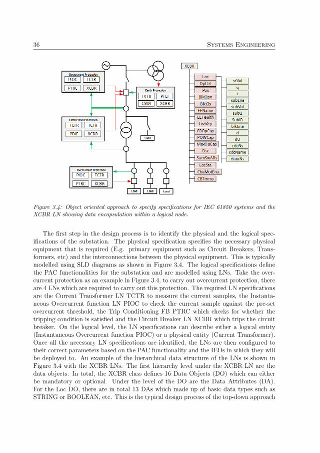
36 Systems Engineering
Figure 3.4: Object oriented approach to specify specifications for IEC 61850 systems and theXCBR LN showing data encapsulation within a logical node.
The first step in the design process is to identify the physical and the logical spec-ifications of the substation. The physical specification specifies the necessary physicalequipment that is required (E.g. primary equipment such as Circuit Breakers, Trans-formers, etc) and the interconnections between the physical equipment. This is typicallymodelled using SLD diagrams as shown in Figure 3.4. The logical specifications definethe PAC functionalities for the substation and are modelled using LNs. Take the over-current protection as an example in Figure 3.4, to carry out overcurrent protection, thereare 4 LNs which are required to carry out this protection. The required LN specificationsare the Current Transformer LN TCTR to measure the current samples, the Instanta-neous Overcurrent function LN PIOC to check the current sample against the pre-setovercurrent threshold, the Trip Conditioning FB PTRC which checks for whether thetripping condition is satisfied and the Circuit Breaker LN XCBR which trips the circuitbreaker. On the logical level, the LN specifications can describe either a logical entity(Instantaneous Overcurrent function PIOC) or a physical entity (Current Transformer).Once all the necessary LN specifications are identified, the LNs are then configured totheir correct parameters based on the PAC functionality and the IEDs in which they willbe deployed to. An example of the hierarchical data structure of the LNs is shown inFigure 3.4 with the XCBR LNs. The first hierarchy level under the XCBR LN are thedata objects. In total, the XCBR class defines 16 Data Objects (DO) which can eitherbe mandatory or optional. Under the level of the DO are the Data Attributes (DA).For the Loc DO, there are in total 13 DAs which made up of basic data types such asSTRING or BOOLEAN, etc. This is the typical design process of the top-down approach

3.4. Synergies between IEC 61499 and IEC 61850 37
where the overall system specification and their interactions are defined first before theindividual specifications are configured and deployed to the IED devices.
IEC 61499 exhibits similar characteristics of encapsulation and modelling philosophywhen defining specifications. Figure 3.5 shows the specification and implementation ofa distributed control system for a didactic demo application implementing LED flashingin configurable patterns. The first step in the design process is to define the specifica-tions of the overall system by means of object orientation with the FB artefacts. Eachphysical component in the FLASHER system can be modelled by an FB. For example,the INTIME FB models the specification of the TIME physical component and the IN-CHOICE FB models the specification of the MODE selector physical component. TheFBs specifications can then be logically connected to model the logical interactions be-tween the FB specifications. Once the overall interaction between the FB specificationsin the whole system is defined, the internal behaviours of the individual FB specificationsare modelled using Execution Control Chart (ECC) state machines. The last step of thedesign process is to distribute the implemented FB specifications to the desired numberof hardware controllers.
Figure 3.5: Object oriented approach to designing a LED flasher controller using IEC 61499[67].
The internal structure of the FB artefacts is shown in Figure 3.6. There are two

38 Systems Engineering
main types of FB artefacts. The first type is the Composite FB and the second type isthe basic FB. Externally, both the composite and the basic FBs looks the same with astandardized type of interfaces. The interface types consist of input events, input data,output event and output data. Internally, however, the two types of FB artefacts are verydifferent. The Composite FB can encapsulate a network of interconnected FBs whichcan either be basic or composite types. The Basic FB is the simplest design artefactwhich consists of one or more algorithms and the ECC specifying the sequence in whichthe algorithms are to be executed based on the transition conditions.
Figure 3.6: Function Block artefacts and their encapsulation.
The synergies between the two standards also extend to the level of the applicationand the device configuration as shown in Figure 3.7. In IEC 61850, the top-most levelof design is the SLD and the LN specifications as defined in the SSD configuration. Atthis level, the specifications are still device-independent specifications. This is akin tothe definition of the Application in IEC 61499 where all the FB specifications and theirinteractions are defined. On the device level, there are also several similarities betweenthe device models from IEC 61850 and IEC 61499. In an IEC 61850 device, there canbe multiple Logical Devices which can encapsulate a subset of the LN specificationsdefined at the SSD level. Similarly, in an IEC 61499 device, there can be multipleexecution containers called Resources, which executes a subset of the FB specificationsfrom the application. It is due to these synergies in design approach and model structurewhich provides the pathway for introducing MDE to systems engineering approach for

3.5. Contribution of Paper A 39
substations based on the industrial standards IEC 61850 and IEC 61499.
Figure 3.7: Comparison between the hierarchical device structure between IEC 61850 and IEC61499.
3.5 Contribution of Paper A
There are many synergies in design approaches between IEC 61850 and IEC 61499 andthe one commonality which is central in linking the two design approaches in existingresearch works is the LN specification from IEC 61850 and the FB specification from IEC61499. Zhabelova et al. propose the iLN structure in [30] which maps LN specification toa composite FB specification. Within the composite FB, there is a database FB and anintelligence FB. The database FB models the hierarchical information model of the LNwhich contains the DO and the DAs and the intelligence FB implements the behaviourof the LN. Zhu et al. [63] and Vlad et al. [68] also propose similar mapping strategiesby representing IEC 61850 LNs as IEC 61499 FBs. Andren et al. in [69] proposean alternative mapping between the specifications by modelling LN specifications asinterfaces of sub-applications. Each sub-application represents a function (e.g. on CircuitTap Changer) while the LNs are used to represent the communication interfaces betweenthe functionalities. The mappings of the specifications in this thesis will be based on the

40 Systems Engineering
iLN mapping structure.The research work carried out in Paper A investigates the capabilities of IEC 61850
and IEC 61499 when MDE engineering methodologies are applied. The methodologyof interest in Paper A was model transformation [48], which is one of the core tenantsof MDE. The goal of the paper was to investigate to what extent can an IEC 61499control system be auto-generated only from IEC 61850 specifications and to ascertainthe capabilities and limitations of using IEC 61850 specifications as the only sourcemodel for model transformation. The unified engineering design flow which combinesIEC 61850 and IEC 61499 engineering approach following the waterfall approach is shownin Figure 3.8 and one possible design process is as follows:
Figure 3.8: Unified Engineering design flow between IEC 61850 and IEC 61499 when followingthe waterfall approach.
1. The first step in the design process is Requirement Elicitation and as mentionedpreviously, both IEC 61850 and IEC 61499 do not have means to formally modelsystem requirements.
2. At the Specification stage, the specifications of the substation are defined and theresultant SCL file is the SSD specification file. The SSD specifies the SLD, the LNspecifications and class type definitions for the LNs that are instantiated in theSSD specification.
3. At the Design stage, the complete configuration of the substation automation sys-tem is designed and the resultant SCL file is the SCD configuration. The SCDconfiguration contains the configurations of the IEDs, the communication betweenthe IEDs, the distribution of the LNs to the IEDs and the parametrization of theLNs. It is at this stage where the cross over in design from IEC 61850 to IEC 61499can be made. The abstract mapping rules from IEC 61850 to IEC 61499 are asfollows:
(a) For all the LN Types that are defined in the DataTypeTemplate section of theSCD, an equivalent FB Type can be created.

3.5. Contribution of Paper A 41
(b) For all the LN type that is instantiated in the substation section of the SCD,the equivalent FB Type can be instantiated in the Application of the IEC61499 system.
(c) For the subset of the LN instances from the substation section that are dis-tributed to the IEDs, the equivalent FB instances are also mapped to theequivalent hardware devices from the Application.
(d) For all the communication configurations of the IEDs, the same configurationis also mapped to the IEC 61499 hardware devices.
Based solely on the SCD configuration, the complete structure of an IEC 61499control program can be created. The summary of all the abstract mapping rulesat the Design stage is shown in Mapping 1 of Table 3.1.
4. At the Implementation stage, the individual IED configurations files are produced.The resultant SCL configuration is the CID configuration file. In IEC 61499, thisis equivalent to the distribution of the implemented FB instances to the hardwaredevices which produces an IEC 61499 XML configuration file to be deployed to thehardware controllers.
5. At the Testing stage, the CID files are deployed and tested to ensure the IEC61850 configurations conform to the specifications set by the IEC 61850 standards.KEMA certification is one such certification which checks for conformance such asthe timing performance and the correctness of the SCL configurations. On the IEC61499 side, testing of the correctness of the implemented control system can beperformed either via software testing under simulation or hardware testing in theloop.
6. The last step is the deployment of the configurations to an IEC 61850 and IEC 61499compatible hardware devices. IEC 61850 configures the communication aspect ofthe hardware device while IEC 61499 configures the functional aspect of the device.
The approach described above naturally follows the engineering flow of the waterfallmodel. Crossover from IEC 61850 to IEC 61499 or vice versa can also be made at otherstages of the design flow. Crossover in design at another level of the design processcan also be made due to the synergies in the design process in the two standards. Forexample, if the crossover were to be done at the Specification stage, the SSD specificationcan be used to generate the FB Type definition from the LN Type definition and theIEC 61499 application can be generated from the substation section of the SSD. Theabstract mapping rules are shown in Mapping 2 of Table 3.1. If the crossover were tobe done at the Implementation level, the CID configuration files can be used to generatethe FB Types, the FB instances that are distributed to the hardware device and thecommunication parametrization of the hardware device. The abstract mapping rules areshown in Mapping 3 of Table 3.1.

42 Systems Engineering
Table 3.1: Engineering design flow and the mappings of elements between IEC 61850 and IEC61499 at each design step
Mapping IEC 61850Configuration
IEC 61499Component
Abstract Mapping Rulesfrom IEC 61850 to IEC61499
1 SCD Whole System
(a) IEC 61850 LNType -〉 IEC61499 FBType
(b) LNType instances in substa-tion section -〉 FBType In-stances in Application
(c) LNType instances in IEDdevice -〉 FBType instancesin device
(d) IED communication config-uration -〉 Device communi-cation configuration
2 SSD Application
(a) IEC 61850 LNType -〉 IEC61499 FBType
(b) LNType instances in substa-tion section -〉 FBType In-stances in Application
3 CID Device Configu-ration (a) IEC 61850 LNType -〉 IEC
61499 FBType
(b) LNType instances in IEDdevice -〉 FBType instancesin device
(c) IED communication config-uration -〉 Device communi-cation configuration
For the purpose of applying model transformation from IEC 61850 to IEC 61499 inPaper A, the following mapping guidelines were created to map IEC 61850 entities toIEC 61499 entities. The mapping guidelines are summarized in Table 3.2:
The mapping of the device model from IEC 61850 to IEC 61499 is relatively straight-

3.5. Contribution of Paper A 43
Table 3.2: Mapping of the model architecture from IEC 61850 to IEC 61499 for MDE modeltransformation
# IEC 61850 Model IEC 61499 Model1 IED Device2 Logical Device Resource3 Logical Node Types (LNType) Composite FB Type4 Data Objects Types (DOType) Structured Data Type5 Data Attribute Types (DAType) Structured Data Type6 EnumType Enumerated Types
forward due to the synergies between the two device models as shown in Figure 3.7. Thedescription of the mapping guidelines are as follows:
1. An IEC 61850 Physical Device is mapped to an IEC 61499 Device.
2. IEC 61850 Logical Devices are mapped to IEC 61499 Resources. In IEC 61850,there can be more than one Logical Devices within a Physical Device. The sameapplies in IEC 61499 where there can be more than one Resource within a Device.
3. A Logical Node Type is mapped to a Composite FB Type. This follows the iLNarchitecture where each LN FB is made up of 2 internal FBs: A Database FB forencapsulating the LN data and an Intelligence FB which implements the behaviourof the FB. Therefore, the FB container needs to be of type Composite.
4. DOTypes and DATypes are mapped to Structured Data Type since these twotypes contain a collection of data members which can be of different types. Therelationships between the LNType, DOType and DAType are as follows. Thehighest level of the information model is the LN. LN contains data members whichare of type DOType. Each DOType contains its own set of data members whichare of type DAType. Each DAType also encapsulates a set of data which can be ofbasic data types (E.g. String, Boolean) or Enumerated Types.
5. EnumTypes are mapped to Enumerated Types in IEC 61499.
Based on these mapping guidelines, model transformation methods were applied inPaper A to investigate the extent to which an IEC 61499 system can be automaticallygenerated based on the IEC 61850 configuration files. Note that the method of transfor-mation at this stage of the investigation was procedural. The mapping rules between thetwo domains from IEC 61850 to IEC 61499 were written based on XML node to nodetransformation since IEC 61850 uses XML for SCL configuration and IEC 61499 also usesXML for its system configuration. The results of Paper A are discussed in section 3.6.

44 Systems Engineering
3.6 Discussion
Based on the results from Paper A and the examination of the systems engineeringapproach of IEC 61850 in the previous sections, the following observations can be made:
1. Firstly, there is lack of a means to formally model requirement in both IEC 61850and IEC 61499.
2. Secondly, if only the IEC 61850 SCL configuration files (specifically the SCD con-figuration) are used as the source model for auto-generating IEC 61499 systems,then it is only possible to auto-generate the structure of an IEC 61499 system.
Regarding the first observation, there are misconceptions of whether LNs are consid-ered as requirements or specifications as it is often used interchangeably by industrialpractitioners, as shown by the result of the recent surveys conducted by the B5.02 CIGREtaskforce group [70]. The B5.02 taskforce group was tasked to investigate how functionalrequirements can be modelled within the context of IEC61850. It is, therefore, necessaryto clarify the differences between requirements and specifications to ascertain which oneof the two categorizations LNs belongs to.
The definition of the functional requirement by the B5.02 taskforce group in the sur-vey paper is as follows:
The functional requirement is a description of the behaviour or the rolea system or part of a system must perform.
An example of a functional requirement based on this definition would be:
”The Transformer should be tripped during overload currents superior to 120% on any ofits coils”
The definition of specifications by the B5.02 taskforce group is as follows:
The Specification describes how a system should be built to attain its Re-quirement
An example of a specification with respect to the functional requirement above wouldbe:
”An overcurrent protection function can be implemented on the primary and secondaryside of the transformer to detect the overload”
By these definitions, the point of distinction between requirement and specification isthat requirements describe WHAT the system need to perform while the specificationdescribes HOW the requirement will be executed. For example, the requirement states

3.6. Discussion 45
that the transformer breakers should be tripped if an overload current is present. The re-quirement states the behaviour but does not specify which of the many possible functionsthat should be used to implement this behaviour. The specification on the other hand,explicitly states the use of the overcurrent function to detect the overload current. Basedon this distinction, LNs would be categorized as specifications rather than requirementssince LNs specifies the specific functionality that should be applied to satisfy the require-ment. E.g. PIOC LN for Overcurrent protection or PDIF LN for Differential protection.The formal modelling of functional requirements is discussed further in depth in Chapter5.
Regarding the second observation, if the SCD configuration file is used as the onlysource model for auto-generation, only the structural model of the IEC 61499 system canbe automatically generated. The IEC 61499 components which are not generated are:
1. The internal implementation of the FBs - I.e. the ECCs and the internal algorithmicimplementation of the FBs.
2. The interconnections between the FBs in the FB network.
These two limitations are due to the lack of formal semantics between the individualLN specification. The semantics we refer to in this context is the relational semanticsbetween the LNs (I.E. how the LNs interact with each other) rather than the naming ofthe data model and the signals. In the IEC 61850 SSD description file, there are threelevels of hierarchy when describing the required functions for the substation. The highestlevel of the hierarchy is the Function and there can be more than one Function withinthe substation. The level below the Function is the Sub-Function and there can also beseveral Sub-Functions within a Function. The level below the Sub-Function is the LNspecification and there can be several LN specifications for each Sub-Function. This levelof hierarchical structure means that a Function is carried out by several Sub-Functionsand the Sub-Functions are expected to be carried out by a set or sets of LNs. This impliesthat there are logical interactions between the LNs specifications within a Sub-Functionand/or between the Sub-Functions. The interactions between the LN specifications canbe one of producer and consumer, where one LN produces data while another LN con-sumes this data. However, for the purpose of maintaining interoperability and flexibilityof the LNs, the behaviour of individual LNs and the semantic relationships between theLNs are not explicitly defined. Although the behaviour of the LNs is implied in its de-scription, the exact operation steps of the implied behaviour are not defined. The samealso applies for the LN to LN interactions where even though the LN descriptions implic-itly suggests possible interactions between LNs, the interactions are also not explicitlystated to maintain interoperability.
From the logical implementation’s point of view, specifically in IEC 61499, the se-mantic relationships between its FB artefacts (mapped entities of LNs) are importantto convey the control flow of the control system and this is represented in IEC 61499as logical connections between the FBs. Since IEC 61499 is an event-based executionsystem which operates on message passing between the FBs, having well-defined message
46 Systems Engineering
passing between FBs is essential. The lack of semantic definition between the LNs meansthat it is impossible to generate a complete IEC 61499 control system with valid logicalconnections between the FBs if only the SCL descriptions are used as the source model.
3.7 Enrichment of Semantics to IEC 61850
The issue of the semantic void in IEC 61850 models have been identified by variousresearchers and there is already ongoing research work which aims to enrich the IEC61850 models. One of the ongoing semantic enrichment efforts is the harmonization ofthe IEC 61850 standards and the Common Information Models (CIM) initiated by theTC57 technical committee [71]. The CIM model is composed of the two standards IEC61968 and IEC 61970 which are designed for Distribution Management System (DMS)and Energy Management Systems (EMS) purposes respectively. The CIM standards andthe IEC 61850 standards were both developed in parallel under two workings groupswithin the TC 57 working group. However, since the standards were designed for differ-ent purposes, there is very little interoperability support between them. Yet there areapplications in the Smart Grid where interaction and exchange of data between thesestandards are necessary.
One of the main benefit of integrating the CIM models to the SCL model is theenrichment of the SLD model in IEC 61850. In IEC 61850, the SLD only describesthe structural layout of the substation components. The CIM standards are also capa-ble of describing the structure of the substation components, but in addition, the CIMstandards also define the relationships between the substation components. Kostic etal. [72] propose the method of harmonization of the information models by mappingthe UML models between the IEC 61850 and CIM standards. Kim et al. [73] providean MDE based approach which model transforms the standard models in IEC 61850and IEC 61970 to a unified semantic model based on the QVT transformation language.QVT is the de-facto language for the model transformation Object Management Group(OMG) standard models which include UML. Santodomingo et al. in [74, 75] proposesa semantic-web approach in harmonizing the two standards by mapping the informationmodels represented as ontology models and applying ontology alignment techniques toharmonize the models. Buchholtz et al. [76] harmonize CIM models with IEC 61850 forthe purpose of developing a common communication and data model for interfacing theelectrical network with the end consumers on the lower voltage network for the purposeof data acquisition from home automation and smart meter systems. Etherden et al.[77] proposes a method based on the integration of IEC 61850 and CIM to implementthe concept of the virtual power plant (Aggregation of DRERs which appears as a singlepower plant [78]) where IEC 61850 is used as the communication interface to the virtualpower plant and the IEC 61850 models are then mapped to CIM models to interface withthe outlying system such as the market traders or the utilities.
The harmonization between CIM and IEC 61850 mainly addresses the semantic gapon the modelling of the substation component. It does not address that semantic gap thatexists on the logical level, specifically the relationships between the logical LN models.
3.8. Chapter Summary 47
This thesis investigates the use of functional requirements as the means to fill the semanticgaps in order to generate a full IEC 61499 control system with valid logical connections.
3.8 Chapter Summary
In this chapter, we examined in depth the synergies between the standards IEC 61850 andIEC 61499 in terms of data modelling and systems engineering approach. The synergiesbetween the two standards include introducing object-orientation in modelling modularcomponents in their respective domains (E.g LN in IEC 61850 and FB in IEC 61499)and systems engineering approach which follows the top-down design methodology.
In paper A, we examined the systems engineering approach from both IEC 61850and IEC 61499 and identified several implementation gaps which need to be addressed inorder to be able to automatically generate an IEC 61499 distributed automation controlsystem from IEC 61850 specifications. The following conclusions can be made:
Firstly, only a partial IEC 61499 distributed automation control system can be au-tomatically generated from a complete SCD specification. The two main componentswhich are not possible to auto-generate from IEC 61850 specifications are the internalimplementation (I.e. the ECCs and the control algorithms) of the FBs and the logicalconnections between the FBs.
Secondly, both IEC 61850 and IEC 61499 are not able to formally model systemrequirements. In traditional systems engineering approaches such as the waterfall model,the first stage of design is the elicitation of systems requirements. In both IEC 61850and IEC 61499, the first stage of design for both standards is the specification stage.
Lastly, there is a lack of relational semantics between the LN specifications. Thiswas intentional on the part of the TC57 technical committee to preserve interoperabilitybetween the LNs. From the perspective of IEC 61499, this is problematic as the logicalconnections between the FBs define the interactions and the overall behaviour of thesystem. It is this lack of relational semantics between the LNs that contributes to thegap in auto-generating logical connections between the FBs.
In the next chapter, we propose the Cyber-Physical Engineering framework, a frame-work which leverages the use of MDE model transformation, semantic web knowledgemodels and IEC 61499 and IEC 61850 domain models to automatically generate CPScontrol systems. The aim of the Cyber-Physical Engineering framework contributes toaddressing the aforementioned implementation gaps.

48 Systems Engineering

Chapter 4
Cyber Physical Engineering
In this chapter, we introduce the Cyber-Physical Engineering framework, a frameworkwhich leverages the use of MDE techniques, semantic web knowledge models and domainmodels to automatically generate CPS systems. This means that the goal is to generateboth the cyber part of the system (E.g. the automation software) and the physical partof the system (E.g. the simulation model of the physical plant) as CPS systems takes intoconsideration both the physical and the cyber part of the system and their interactions.
The chapter first introduces the overall CPE framework. Secondly, the motivation forthe use of semantic web modelling language is discussed. Lastly, the framework whichis developed for model transforming semantic web modelling language Web OntologyLanguage (OWL) is discussed.
4.1 Cyber Physical Engineering Framework
We propose the framework called Cyber-Physical Engineering, an MDE framework withthe main goal of automatically generating the distributed control system of CPS systemsfrom the physical and cyber requirements and specifications. In addition, the CPEframework also aims to automatically generate the simulation plant model of the CPSsystem for the testing and validation of the distributed control system. The proposedCPE framework is shown in Figure 4.1 and central to the CPE framework is the leveragingof semantic web models and the model transformation of the semantic web models as thesource and the target model of transformation.
The CPE framework consists of three main model transformations and the transfor-mations are as follows:
1. The first model transformation is the transformation of the domain-specific modelsto the common semantic model. This model transformation consolidates the sourcemodels into a unified formal model that models the semantic relationships betweenthe domain entities and creates the source semantic model for model transforma-tion.
49

50 Cyber Physical Engineering
Figure 4.1: Cyber-Physical Engineering Framework.
2. The second model transformation is the transformation of the source semanticmodel to the target semantic model. I.e. the requirements and the specificationsto the distributed control system and the simulation model of the plant.
3. The last model transformation is the transformation from the target semantic modelto the domain specific models.
The CPE framework presented in Figure 4.1 is an overview of the CPE frameworkwhich can be applied to the engineering of distributed control systems for multi-domainCPS systems. The CPE framework that is applicable for the energy domain is introducedin Section 4.2.
4.2 CPE Framework in the Energy Domain
The proposed CPE framework for the energy domain is shown in Figure 4.2. The aim ofthe CPE framework is to automatically generate distributed substation automation con-trol systems with valid control flow from system requirements and IEC 61850 substationspecifications. The CPE framework is based on the leveraging of model transformationand semantic web models, specifically the OWL ontology modelling language that incor-porates formal models of system requirements to address the lack of a control flow inthe IEC 61499 distributed control system that was identified in Paper A. In this frame-work, there are three domains of knowledge that are incorporated. The first domain isthe model of the system requirements. The second is the model of the system specifica-tions and communication configurations. The third domain is the distributed automationcontrol domain which implements the specifications.
Central to the CPE framework is the use of semantic web models and the motivationbehind the use of semantic models for the energy domain as the core unified modellinglanguage are as follows:
1. The first reason is due to the fact that ontological languages such as OWL providemodelling artefacts which can model domain concepts and express the relationships

4.2. CPE Framework in the Energy Domain 51
Figure 4.2: CPE framework for the Energy Domain.
between the ontological concepts. Ontology modelling languages are capable ofmodelling modular components and is adept at expressing the relationships betweenthe modular components.
2. The second reason is due to the multi-domain nature of the Smart Grid as illus-trated by the SGAM model in Figure 2.6. This CPE framework incorporates threedomains each with its own domain specific model, semantics and varying degreesof model formality. Semantic web models are used due to their capability to modelmulti-domain systems and in addition, it is more practical to develop transforma-tion rules for models with the same underlying model semantics rather than a setof transformation rules for each domain model. It is also beneficial from the sys-tems design perspective to have a high abstraction model show the cross-domainrelationships in the system.
3. Lastly, ontologies have already been used in existing Smart Grid research projectsfor the purpose of harmonizing industrial standards. One example is the IEC61850 and CIM harmonization research work by Santodomingo et al. in [74, 75]which models IEC 61850 and CIM concepts in ontology models respectively beforeontology matching techniques are applied to match the information models in bothsets of standards. Another usage of ontology is by Pala et al. [79] which modelsCIM as semantic web RDF graphs for auto-generating CID configurations fromCIM and CID files. These existing research works demonstrate the viability ofutilizing semantic webs models to model multi-domain systems in the Smart Grid.
The engineering process of the proposed CPE framework according to Figure 4.2 areas follows:
1. Firstly, system requirements are developed and modelled in ontological modelswritten in the OWL ontology language.
2. Secondly, the specifications are identified based on the system requirements andrepresented in IEC 61850 SCL configuration in XML. The XML representation isthen model transformed to its ontological representation.
52 Cyber Physical Engineering
3. Thirdly, transformation rules are developed which transforms the ontological repre-sentation of the requirements and/or the specification to the distributed IEC 61499automation control ontological model.
4. Lastly, the target ontology model is then transformed to its domain representation.In the case of IEC 61499, the configuration is represented by XML.
The main components of the proposed CPE model transformation framework are asfollows:
1. Requirements: The aim of system requirements is to specify the behaviour of thesystem. There are several types of system requirements which includes functional,non-functional and timing requirements, etc. System requirements are typicallyrepresented in Natural Languages (NL) since it is easily understood and docu-mented by stakeholders who typically have a different level of technical expertise.However, system requirements which are represented in NL are not considered tobe formal and therefore, is not computer interpretable. Therefore, the informalNL based systems requirements are mapped to its formal representation in OWLontology. The type of system requirements in this thesis is restricted to functionalrequirements.
2. Specifications: The specifications of the communication, device and functionmodels are modelled in IEC 61850 by means of LNs and SLDs in SCL configu-ration files. The SCL is represented in the XML language and can be used toconfigure IEC 61850 compliant IED devices. The strength of XML is its capabil-ity to model the hierarchal structure of the information and device models of IEC61850 systems. However, XML is not suitable for representing semantics. TheXML representation can be converted to an OWL representation by transformingUML class diagrams to OWL ontology.
3. Model Transformation: One of the core tenants of MDE is model transformationand the process of model transformation involves transforming a source model toa target model by means of transformation rules. The transformation rules definethe cross-domain mappings of the entities between the source model to the targetmodel. In the CPE framework, the source model is the requirement and the spec-ification model and the target model is the IEC 61499 distributed control model.The transformation rules are developed using the Extended Semantic Web RuleLanguage (eSWRL), an OWL ontology transformation language that extends theOWL reasoning language Semantic Web Rule Language (SWRL) for the purposeof model transforming ontologies.
4. Testing: The resultant model from the model transformation is an ontology modelwhich will need to be transformed again to its domain-specific representation. Theconfiguration of IEC 61499 control system is described in XML and therefore, theresultant IEC 61499 ontological model is mapped to its XML representation. At this

4.3. Ontology Driven MDE 53
stage, the control system can be tested for the correctness of the system behaviourby either validation or verification. There are different methods of validating andverifying the correctness of the generated IEC 61499 control system. Model check-ing is one of the formal verification approaches [80, 81, 82] that is used to prove ordisapprove certain properties in the control system by exploring the state-space ofthe control system with counterexamples. There is existing research works whichapply model checking to verify IEC 61499 control systems [83, 84, 85, 86, 87].Requirement tracing [88, 89, 90] is used in software engineering to trace how therequirements are implemented in the end control system and there are existing re-search works [91, 92, 93] which introduce requirement tracing to trace IEC 61499distributed control systems. Software co-simulation is another approach which canbe used to validate the overall behaviour of IEC 61499 control system [30, 52, 94].In this thesis, we explore the use of scripted software co-simulation to validate thecorrectness of the auto-generated IEC 61499 control system, much like the prac-tice of black-box testing to validate the auto-generated IEC 61499 control systemagainst the system requirements.
4.3 Ontology Driven MDE
The core principle of the CPE framework is based on the leveraging of knowledge-basedontological models in both the modelling of the system and model transformation. How-ever, there are several implementation challenges that must be addressed during thedevelopment of the CPE framework. These implementation challenges include the map-ping of the DSM models to ontological models and the development of the transformationengine for model transforming ontological models.
The following subsection firstly describes the mapping between the DSM models tothe OWL models and secondly, the development of the eSWRL ontology transformationengine.
4.3.1 Modelling in Ontology
The advent of knowledge-based modelling was driven by the notion of the so-called Se-mantic Web [95], a world wide web that is enriched with semantic information that allowssystems to access information on a more efficient manner. The goal of OWL is to providea language for developing domain ontologies on the world wide web. Ontological modelsare central to semantic web applications and a commonly accepted definition of an on-tology as defined by Gruber [96] and later Borst [97] is: ”An ontology is an explicit andformal specification of a conceptualization of a shared domain of interest.” This defini-tion implies that the conceptualization of the domain is formal and is, therefore, machineinterpretable and can be subject to reasoning. Ontological models are commonly usedto formally model the structure of a system, which includes the relevant entities and itsrelations [98]. An ontology can be considered as a 4-tuple 〈C,R, I, A〉 [99] where the fourelements are Concepts, Relations, Instances and Axioms. A concept refers to a class of

54 Cyber Physical Engineering
entities that exists within a domain. Relations refers to the interactions that can existeither between concepts or between a concept and its properties. Instances are ”things”which represent a class or concept. Axioms are used to associate classes and propertieswith specifications of their characteristics in order to add logical information about theclass and the properties. These could be constraints to data properties or relationshipsbetween class concepts. An example of an ontological model is shown in Figure 4.3 whichshows a simplified structure of the IEC 61850 SCL file.
Figure 4.3: Simple ontology model showing structure of the SCL configuration file.
The yellow box represents the class concepts and the black arrow represents the objectrelationships between the concepts. The white ovals represent the class instances and thegreen lines represent the data properties of the instances. Note that a typical ontologycomprises of two components: a T-Box (a terminological component) and an A-Box (anassertion component) [99]. The T-Box defines class concepts and A-Box contains theinstances of the class concepts and its assertions. The combination of the T-Box and theA-Box forms a knowledge base. T-Box are static definitions which remain unchangedwhile A-Box can change over time as more assertions are made. In the context of thisthesis, only the T-Box of the IEC 61850 and IEC 61499 need to be statically createdas the A-Box are generated during model transformation. The next two subsections

4.3. Ontology Driven MDE 55
describe the method of developing the T-Box ontology for IEC 61850 and IEC 61499.The development of the T-Box ontology for the functional requirements is discussed inChapter 5.
Modelling IEC 61850 T-Box Ontology
The definition of the T-Box ontology for IEC 61850 is derived from the UML descriptionas prescribed in the SCL configuration language. The UML description provides theabstract models of the substation domain and contains the definition for the devicemodels, data models, functional hierarchy and the data exchanges between the devicesand applications. There is already existing research work which defines mapping rules fortransforming UML diagrams to OWL ontologies as shown in [100, 101, 102, 103]. In thisthesis, we have adopted the mapping rules defined by Zedlitz et al. in [104]. It is worthnoting that UML is developed under the notion of Closed-World Assumption (CWA)[105] meaning that any knowledge which is not explicitly defined are considered false. Incontrast, Ontology operates under the Open-World Assumption (OWA), meaning thatany knowledge which is not explicitly defined are treated as unknown. Therefore, it isnecessary to place stricter restrictions on the OWL models. The conversion from theIEC 61850 UML model to OWL T-Box was done manually as it was only necessaryto develop the T-Box once since it is the static part of the OWL model and does notundergo modification during ontology transformation. A summary of the conversion rulesfor mapping the classes and the properties from UML to OWL are as follows:
1. Classes (owl:class): Each UML class is mapped to an OWL class. The naming ofthe UML class is retained in the OWL class.
2. Object Property (owl:ObjectProperty): Associations between UML class aredefined as Object Properties following the structure of Has 〈Class〉, where the”Has ” prefix denotes that the property is of type object property and the optionalfield ”〈Class〉” defines the class that the object property is linked to. The Domainof the Object Property specifies the class in which the object property is linkedfrom and the Range specifies the class the object property is linked to.
3. Data Property (owl:DataProperty): Class-Dependent Attributes of UML classare defined as data properties following the structure has 〈AttributeName〉, wherethe ”has ” prefix denotes that the property is of type data property and the〈AttributeName〉 defines the name of the class attribute. The Domain of the dataproperty specifies the concept that the property belongs to and the Range specifiesthe data type which describes the value of the data property.
4. The conversion of cardinality from UML to Owl is defined in Table 4.1.
The UML definition of the SCL domain is shown in Figure 4.4. The conversion of theSCL UML definition to OWL is as follows:

56 Cyber Physical Engineering
Table 4.1: Cardinality Restrictions in OWL converted from UMLMultiplicity Cardinality Constraints in OWL Description0..0 OWL:qualifiedCardinality = 0 No instances0..1 OWL:maxQualifiedCardinality = 1 At most one instance0..* OWL:minQualifiedCardinality = 0 Zeor or more instances1..1 OWL:qualifiedCardinality = 1 Exactly one instance1..* OWL:minQualifiedCardinality = 1 At least one instance
Figure 4.4: UML definition of the SCL class.
1. Each UML class from Figure 4.4 is mapped to an OWL class as shown in List-ing 4.1. The created classes were SCL, Header, Communication, Substation, IEDand DataTypeTemplates.
<owl : Class rd f : about=”#SCL”/><owl : Class rd f : about=”#Header”/><owl : Class rd f : about=”#Substat ion”/><owl : Class rd f : about=”#Communication”/><owl : Class rd f : about=”#IED”/><owl : Class rd f : about=”#DataTypeTemplates”/>
Listing 4.1: IEC 61850 class definitions of the SCL
2. Object properties between the SCL class and the Header, Substation, Communica-tion, IED and DataTypeTemplates classes are defined in the format ”Has 〈Class〉”as shown in Listing 4.2. In total, there are five object properties, one object prop-erty each to associate the SCL class with the Header, Substation, Communication,IED and the DataTypeTemplates class. For example, to associate the SCL classwith the IED class, the Has IED object property is created. The domain of theHas IED object property is the SCL class and the range is the IED class.

4.3. Ontology Driven MDE 57
<owl : ObjectProperty rd f : about=”#Has Communication”><r d f s : domain rd f : r e s ou r c e=”#SCL”/><r d f s : range rd f : r e s ou r c e=”#Communication”/></owl : ObjectProperty><owl : ObjectProperty rd f : about=”#Has DataTypeTemplates”><r d f s : domain rd f : r e s ou r c e=”#SCL”/><r d f s : range rd f : r e s ou r c e=”#DataTypeTemplates”/></owl : ObjectProperty><owl : ObjectProperty rd f : about=”#Has Header”><r d f s : domain rd f : r e s ou r c e=”#SCL”/><r d f s : range rd f : r e s ou r c e=”#Header”/></owl : ObjectProperty><owl : ObjectProperty rd f : about=”#Has IED”><r d f s : domain rd f : r e s ou r c e=”#SCL”/><r d f s : range rd f : r e s ou r c e=”#IED”/></owl : ObjectProperty><owl : ObjectProperty rd f : about=”#Has Substat ion”><r d f s : domain rd f : r e s ou r c e=”#SCL”/><r d f s : range rd f : r e s ou r c e=”#Substat ion”/></owl : ObjectProperty>
Listing 4.2: OWL defintion of the SCL Object Properties
3. Data properties for the SCL class is defined in the format ”has 〈Attribute〉” asshown in Listing 4.3. In the UML definition of the SCL class in Figure 4.4, the twodata properties are the has revision property and the has version property.
<owl : DatatypeProperty rd f : about=”#h a s r e v i s i o n”><r d f s : range rd f : r e s ou r c e=”#s t r i n g ”/></owl : DatatypeProperty><owl : DatatypeProperty rd f : about=”#h a s v e r s i o n”><r d f s : range rd f : r e s ou r c e=”#s t r i n g ”/></owl : DatatypeProperty>
Listing 4.3: Data Property Definition
4. The cardinality restrictions of the SCL class is shown in Listing 4.4. In total,there are five cardinal restrictions that is associated to the SCL class. Accordingto Figure 4.4, an instance of the SCL class can only be associated with exactlyone instance of the Header class. The OWL:minQualifiedCardinality restriction isplaced on the Has Header object property with a value of 1.
<rd f : De s c r ip t i on rd f : about=”#Thing”><r d f s : subClassOf><owl : Class>

58 Cyber Physical Engineering
<owl : i n t e r s e c t i o n O f rd f : parseType=”C o l l e c t i o n”><owl : Re s t r i c t i on><owl : onProperty rd f : r e s ou r c e=”#Has IED”/><owl : m inQua l i f i edCard ina l i ty rd f : datatype=
”#nonNegat iveInteger”>0</owl : minQua l i f i edCard ina l i ty><owl : onClass rd f : r e s ou r c e=”#IED”/></owl : Re s t r i c t i o n><owl : Re s t r i c t i on><owl : onProperty rd f : r e s ou r c e=”#Has Substat ion”/><owl : m inQua l i f i edCard ina l i ty rd f : datatype=
”#nonNegat iveInteger”>0</owl : minQua l i f i edCard ina l i ty><owl : onClass rd f : r e s ou r c e=”#Substat ion”/></owl : Re s t r i c t i o n><owl : Re s t r i c t i on><owl : onProperty rd f : r e s ou r c e=”#Has Header”/><owl : q u a l i f i e d C a r d i n a l i t y rd f : datatype=
”#nonNegat iveInteger”>1</owl : q u a l i f i e d C a r d i n a l i t y><owl : onClass rd f : r e s ou r c e=”#Header”/></owl : Re s t r i c t i o n><owl : Re s t r i c t i on><owl : onProperty rd f : r e s ou r c e=”#Has Communication”/><owl : maxQual i f i edCard ina l i ty rd f : datatype=
”#nonNegat iveInteger”>1</owl : maxQual i f i edCard ina l i ty><owl : onClass rd f : r e s ou r c e=”#Communication”/></owl : Re s t r i c t i o n><owl : Re s t r i c t i on><owl : onProperty rd f : r e s ou r c e=”#Has DataTypeTemplates”/><owl : maxQual i f i edCard ina l i ty rd f : datatype=
”#nonNegat iveInteger”>1</owl : maxQual i f i edCard ina l i ty><owl : onClass rd f : r e s ou r c e=”#DataTypeTemplates”/></owl : Re s t r i c t i o n></owl : i n t e r s e c t i o n O f></owl : Class></r d f s : subClassOf></rd f : Descr ipt ion>
Listing 4.4: Cardinality restriction of the SCL class
In total, there were six UML models that were converted to OWL. The six UML modelwere SCL, Header, IED, Communication, Substation and DataTypeTemplates. In thecontext of the current implementation of the CPE framework, the most relevant UMLmodels are the DataTypeTemplates and the IED models. An example of the convertedOWL model is the simplified graphical representation of the DataTypeTemplates T-Boxmodel as shown in Figure 4.5. The grey box denotes the OWL classes. The red arrow

4.3. Ontology Driven MDE 59
and label denotes the Object Properties, the green labels denote the cardinality and theblue labels denotes the data properties. The DataTypeTemplates defines the data modelfor the Logical Node Types (LNodeType), the Data Object Types (DOType), the DataAttribute Types (DATypes) and the EnumTypes.
Figure 4.5: Graphical representation of the DataTypeTemplates OWL model
.
Modelling of IEC 61499 T-Box Ontology
The definition of the T-Box ontology for IEC 61499 is derived from the IEC 61499Document Type Definition (DTD) schema [51] which describes the data, structure andrelationships between the entities in IEC 61499. Similar to the development of the IEC61850 ontology, since the T-Box of the IEC 61499 ontology only need to be createdonce, the mapping from IEC 61499 DTD to IEC 61499 OWL is also done manually.The mapping rules are adopted from the work by Thuy et al. in [106] and the maintransformation rules are as follows:
1. Classes (owl:class): An OWL class is created for each element which follows theElement definition 〈 !Element element-name (element-content) 〉. An example ofan Element definition is the FBType Element definition below:
〈 !ELEMENT FBType (Identification?,VersionInfo+,CompilerInfo?,InterfaceList,(BasicFB | FBNetwork)?, Service?) 〉
Based on this Element definition, an FBType OWL class is created and the value

60 Cyber Physical Engineering
of the element-name field is taken as the unique name for the OWL class. I.e.FBType.
2. Object Property (owl:ObjectProperty): For nested Elements, an object propertyis created to describe the nest relationships between the parent Element and thechild Element. The object property is based on the structure ”Has 〈 childElement〉”, where the ”Has ” prefix denotes that the property is of type object propertyand the ”〈 childElement 〉” field denotes the nested child of the parent Element.This denotation is also represented by the Domain and Range of the object prop-erty where the Domain is the parent Element and the Range is the child Element.Referring to the Element definition for FBType, The element-content field consistsof the values Identification?, VersionInfo+, CompilerInfo?, InterfaceList. Each oneof these values has its own Element definition and therefore, they are all consideredas the child Element of the parent FBType Element. To describe the nested rela-tionships between FBType and InterfaceList, the object property Has InterfaceListis created with the Domain set to FBType and the Range set to InterfaceList.
3. Data Property (owl:DataProperty): Data properties are created from the Attlistdefinition where each value defined under the attribute is converted to a data at-tribute. The data property is based on the structure ”has 〈Attribute〉”, where the”has ” prefix denotes the property is of type data property and the ”〈Attribute〉”field denotes the name of the attribute. The domain of the data property is set tothe class in which the attribute belongs to and the range is set to datatype of theattribute value. An example of an Attlist definition is as follows:
〈 !ATTLIST FBTypeName CDATA #REQUIREDComment CDATA #IMPLIED 〉
The Attlist definition defines two attributes for the class FBType. For the FBTypeclass, the two data properties that will be created are has name and has comment.The Domain of both these data properties are set to FBType and the Range is setto the OWL string type xsd:string.
4. The conversion of cardinality from DTD to Owl is defined in Table 4.2:
In total, there are three DTD specifications defined in the IEC 61499 standard andthe DTD specifications are as follows:
1. DataType: The DataType DTD specification defines the structure and class ofthe data types that are allowed in IEC 61499.
2. Library Elements: The Library Element DTD specification defines the structureof the IEC 61499 design elements. The design elements include the definition forthe FBType, AdapterType, ResourceType, DeviceType, System, SubAppType andthe Network.

4.3. Ontology Driven MDE 61
Table 4.2: Cardinality Restrictions in OWL converted from DTDMultiplicity Cardinality Constraints in
OWLDescription
+ OWL:minQualifiedCardinality =1
At least one instances
? OWL:maxQualifiedCardinality =1
At most one instance
* OWL:minQualifiedCardinality =0
Zeor or more instances
#IMPLIED OWL:Cardinality = 0 Instance is optional#REQUIRED OWL:qualifiedCardinality = 1 Exactly one instance#FIXED OWL:hasValue Value is as defined
Figure 4.6: Simplified visual representation of the FBType OWL model.
3. FBMGT: The Function Block Management DTD specification which defines thecommunication protocols between IEC 61499 devices.
Both the Library Elements and the DataType DTD definition were converted to OWLin the context of this thesis. An example of the converted OWL from DTD definitionis shown in Figure 4.6, which is a simplified visual representation of the FBType libraryelement.
The elements in the OWL model are as follows:
1. As defined in the DTD definition, the classes in which the FBType class can haveare Identification, VersionInfo, BasicFB, InterfaceList, FBNetwork, Service and theCompilerInfo class. The definition of these classes in OWL is shown in Listing 4.5.
<owl : Class rd f : about=”#BasicFB”/><owl : Class rd f : about=”#Compi lerInfo”/><owl : Class rd f : about=”#FBNetwork”/>

62 Cyber Physical Engineering
<owl : Class rd f : about=”#FBType”/><owl : Class rd f : about=”#I d e n t i f i c a t i o n ”/><owl : Class rd f : about=”#I n t e r f a c e L i s t ”/><owl : Class rd f : about=”#S e r v i c e ”/><owl : Class rd f : about=”#Vers i on In fo”/>
Listing 4.5: OWL class definition of the FBType class and its associated classes
2. Each class that is associated with the FBType class is modelled as an object prop-erty following the structure Has 〈 childElement 〉. The Domain of the object prop-erty is set to the source associate (FBType) and the Range is set to the associatedtarget class. The OWL definition of the object properties is shown in Listing 4.6.
<owl : ObjectProperty rd f : about=”#Has BasicFB”><r d f s : domain rd f : r e s ou r c e=”#FBType”/><r d f s : range rd f : r e s ou r c e=”#BasicFB”/></owl : ObjectProperty><owl : ObjectProperty rd f : about=”#Has Compi lerInfo”><r d f s : domain rd f : r e s ou r c e=”#FBType”/><r d f s : range rd f : r e s ou r c e=”#Compi lerInfo”/></owl : ObjectProperty><owl : ObjectProperty rd f : about=”#Has FBNetwork”><r d f s : domain rd f : r e s ou r c e=”#FBType”/><r d f s : range rd f : r e s ou r c e=”#FBNetwork”/></owl : ObjectProperty><owl : ObjectProperty rd f : about=”#H a s I d e n t i f i c a t i o n”><r d f s : domain rd f : r e s ou r c e=”#FBType”/><r d f s : range rd f : r e s ou r c e=”#I d e n t i f i c a t i o n ”/></owl : ObjectProperty><owl : ObjectProperty rd f : about=”#H a s I n t e r f a c e L i s t”><r d f s : domain rd f : r e s ou r c e=”#FBType”/><r d f s : range rd f : r e s ou r c e=”#I n t e r f a c e L i s t ”/></owl : ObjectProperty><owl : ObjectProperty rd f : about=”#Has Serv i ce”><r d f s : domain rd f : r e s ou r c e=”#FBType”/><r d f s : range rd f : r e s ou r c e=”#S e r v i c e ”/></owl : ObjectProperty><owl : ObjectProperty rd f : about=”#Has Vers ionIn fo”><r d f s : domain rd f : r e s ou r c e=”#FBType”/><r d f s : range rd f : r e s ou r c e=”#Vers i on In fo”/></owl : ObjectProperty>
Listing 4.6: Object property definitions of the FBType class in OWL

4.3. Ontology Driven MDE 63
3. In the FBType class, there are two data properties. The data properties follow thestructure has 〈 dataAttribute 〉. The Domain of the data property is set to the classin which the attribute belongs to and the Range is the datatype of the attribute.The OWL definition of the data properties has comment and has name is shownin Listing 4.7.
<owl : DatatypeProperty rd f : about=”#has comment”><r d f s : domain rd f : r e s ou r c e=”#FBType”/><r d f s : range rd f : r e s ou r c e=”#s t r i n g ”/></owl : DatatypeProperty><owl : DatatypeProperty rd f : about=”#has name”><r d f s : domain rd f : r e s ou r c e=”#FBType”/><r d f s : range rd f : r e s ou r c e=”#s t r i n g ”/></owl : DatatypeProperty>
Listing 4.7: Data property definitions of the FBType class in OWL
4. The cardinality restriction of the FBType class is shown in Listing 4.8. The Elementdefinition of the FBType class:
〈 !ELEMENT FBType (Identification?,VersionInfo+,CompilerInfo?,InterfaceList,(BasicFB vert FBNetwork)?, Service?) 〉.Based on this definition, an FBType can have at max 1 Identification, CompilerInfoand Service, at min 1 VersionInfo, exactly 1 InterfaceList and either exactly 1BasicFB or exactly 1 FBNetwork.
<owl : Class rd f : about=”#FBType”><r d f s : subClassOf><owl : Class><owl : i n t e r s e c t i o n O f rd f : parseType=”C o l l e c t i o n”><owl : Class><owl : unionOf rd f : parseType=”C o l l e c t i o n”><owl : Re s t r i c t i on><owl : onProperty rd f : r e s ou r c e=”#Has BasicFB”/><owl : q u a l i f i e d C a r d i n a l i t y rd f : datatype=
”#nonNegat iveInteger”>1</owl : q u a l i f i e d C a r d i n a l i t y><owl : onClass rd f : r e s ou r c e=”#BasicFB”/></owl : Re s t r i c t i o n><owl : Re s t r i c t i on><owl : onProperty rd f : r e s ou r c e=”#Has FBNetwork”/><owl : q u a l i f i e d C a r d i n a l i t y rd f : datatype=
”#nonNegat iveInteger”>1</owl : q u a l i f i e d C a r d i n a l i t y><owl : onClass rd f : r e s ou r c e=”#FBNetwork”/></owl : Re s t r i c t i o n></owl : unionOf>

64 Cyber Physical Engineering
</owl : Class><owl : Re s t r i c t i on><owl : onProperty rd f : r e s ou r c e=”#Has Vers ionIn fo”/><owl : m inQua l i f i edCard ina l i ty rd f : datatype=
”#nonNegat iveInteger”>1</owl : minQua l i f i edCard ina l i ty><owl : onClass rd f : r e s ou r c e=”#Vers i on In fo”/></owl : Re s t r i c t i o n><owl : Re s t r i c t i on><owl : onProperty rd f : r e s ou r c e=”#H a s I n t e r f a c e L i s t ”/><owl : q u a l i f i e d C a r d i n a l i t y rd f : datatype=
”#nonNegat iveInteger”>1</owl : q u a l i f i e d C a r d i n a l i t y><owl : onClass rd f : r e s ou r c e=”#I n t e r f a c e L i s t ”/></owl : Re s t r i c t i o n><owl : Re s t r i c t i on><owl : onProperty rd f : r e s ou r c e=”#Has Compi lerInfo”/><owl : maxQual i f i edCard ina l i ty rd f : datatype=
”#nonNegat iveInteger”>1</owl : maxQual i f i edCard ina l i ty><owl : onClass rd f : r e s ou r c e=”#Compi lerInfo”/></owl : Re s t r i c t i o n><owl : Re s t r i c t i on><owl : onProperty rd f : r e s ou r c e=”#H a s I d e n t i f i c a t i o n ”/><owl : maxQual i f i edCard ina l i ty rd f : datatype=
”#nonNegat iveInteger”>1</owl : maxQual i f i edCard ina l i ty><owl : onClass rd f : r e s ou r c e=”#I d e n t i f i c a t i o n ”/></owl : Re s t r i c t i o n><owl : Re s t r i c t i on><owl : onProperty rd f : r e s ou r c e=”#Has Serv i ce”/><owl : maxQual i f i edCard ina l i ty rd f : datatype=
”#nonNegat iveInteger”>1</owl : maxQual i f i edCard ina l i ty><owl : onClass rd f : r e s ou r c e=”#S e r v i c e ”/></owl : Re s t r i c t i o n></owl : i n t e r s e c t i o n O f></owl : Class></r d f s : subClassOf></owl : Class>
Listing 4.8: Data property definitions of the FBType class in OWL
4.4 eSWRL: Ontology Transformation Language
The model transformation engine of the CPE framework is based on the leveraging of thesemantic web models. One of the main advantages of utilizing semantic web models is thewide support of reasoning tools that can be used to reason the ontology to infer additional

4.4. eSWRL: Ontology Transformation Language 65
knowledge about the domain. However, because of the open-world assumption notionwhich ontology operates under, many of the reasoning languages are restricted fromcreating new instances or properties in the ontology and therefore, existing reasoninglanguages are not suitable for the purpose of model transformation. Therefore, there isneed to develop a transformation language for the purpose of transforming ontologiesand secondly, a transformation engine to perform the transformation.
The following subsection is structured as follows: Firstly, we describe the motiva-tion behind the need for an ontology transformation language. Secondly, we present theeSWRL ontology transformation language and lastly, we present the ontology transfor-mation engine developed in Prolog.
4.4.1 MDE with UML
There are several MDE frameworks, one of which is the Model-Driven Architecture(MDA) presented by the OMG centres on the use of several of OMG’s standards whichinclude the Unified Modelling Language (UML) [107]. The goal of the MDA frameworkis to introduce a vendor-neutral approach to the design of large complex systems. Theframework is based on the leveraging of platform-independent models that can be used tomodel the functionality and the behaviour of the system. In the context of MDA, OMG’sUnified Modelling Language (UML) is the most commonly used modelling language forthe purpose of high-level platform-independent modelling. Model transformation is acore component of MDE and a supporting transformation language is required to de-scribe and develop the transformation rules for transforming the models. In the contextof MDA, OMG’s Query/View/Transformation (QVT) [108] is the standard language forspecifying model transformations from the source models to target models. QVT stan-dardizes three model transformation languages which operate on the models that conformto the MetaObject Facility (MOF) 2.0 metamodels from OMG. Another transformationlanguage that is widely used for model transforming UML is the Atlas TransformationLanguage (ATL) [109]. ATL transformation is a rule-based model transformation lan-guage where the constraints in the transformation rules are formalized based on the Ob-ject Constraint Language (OCL) expressions. ATL is a hybrid transformation languagewhere rules are defined in both declarative and imperative manner.
UML is an amalgamation of several modelling languages in the software engineeringdomain with the aim of introducing object-oriented design methods for industrial use. Itis used for documenting and sharing designs and therefore, the design notations in UMLare graphical rather than formal. There are pathways of incorporating formal constraintsinto UML models, but this requires the addition of auxiliary formal constraint languagessuch as OCL. In total, UML 2.0 defines 13 different types of diagrams divided into 3categories, each providing a different perspective of the system design. The first categoryis the Structure Diagrams which models the static structure of the system. There are 6diagram types which consist of Class Diagram, Package Diagram, Deployment Diagram,Component Diagram, Object Diagram and Composite Structure Diagram. The secondcategory is the Behaviour Diagrams which models the behaviour of the system. There

66 Cyber Physical Engineering
are three diagram types and the diagrams are the Use Case Diagram, Activity Diagramand the State Machine Diagram. The last category is the Interaction Diagrams whichmodels the Interactions within the system. There are three diagram types and they areSequence Diagram, Communication Diagram, Timing Diagram and Interaction OverviewDiagram.
UML is used widely for modelling software systems and the advantages of using UMLincludes:
1. Ease of sharing: UML is a visual modelling language with the purpose of sharingsystem design documents between domain experts with different level of expertise.Visual languages are better at conveying relationships between entities comparedto text-based modelling languages;
2. Multiple views of abstraction: In total, UML has 13 diagrams which providesupport for multiple viewpoints of abstraction. Each diagram provides a detailedabstraction of the design in interest and serves as a means of decomposing complexsoftware systems into smaller sub-systems. In addition, these abstraction mod-els also serve as a means of design documentation for reuse in future projects.Especially in modern systems where a system can undergo several iterations ofdevelopment in its life cycle.
3. Tool Support: It’s widely adopted in software engineering with mature tool sup-port.
In contrast, there are also distinctive disadvantages of using UML as the modellinglanguage for MDE.
1. Not a formal language: As mentioned before, the design notations of UMLdiagrams are based on visual notations rather than formal notations as one of theintended goal of UML is for it to be shared and understood by humans. Withouta formal foundation, it is difficult for machines to interpret UML diagrams.
2. Not Interoperable: Despite the fact that OMG standardizes the modelling con-cepts and notations in many of the diagrams within UML, the UML diagrams arenot interoperable. That is it is difficult to exchange model information between thedifferent diagrams.
3. Lack of a common semantic: Since it is a collection of diagrams, there isno unified modelling semantics between the diagrams. This is problematic whendeveloping transformation rules using imperative languages as the transformationrules become dependent on the type of UML diagram that is used as the sourcemodel
4. Imperative transformation languages: Many of the existing UML transfor-mation languages are imperative transformation languages, which means that thedevelopers of the transformation rules need to explicitly define the steps in which

4.4. eSWRL: Ontology Transformation Language 67
the models are to be transformed. This includes explicit instruction on how tofetch the data model and requires knowledge of the structuring of the data withinthe model. This means the transformation rules becomes model dependent and thetransformation rules need to be rewritten if there is a change in the data structure.
4.4.2 MDE based ontological models
Ontology-driven engineering approaches are increasingly being adopted in the field ofsoftware engineering [110]. Ontology models are designed to be interpreted by machinesrather than humans and therefore, contains a greater formal foundation. There areseveral formal modelling languages for modelling ontologies and OWL by OMG is oneof the most widely used ontology modelling languages. The formal foundation of OWLis based on description logic and therefore, can be reasoned for consistency and to inferadditional knowledge about the domain which already exist, but is not explicitly defined.Reasoning over OWL models is a more powerful means of reasoning (More complicatedrelations can be represented). The advantages of utilizing ontological models over UMLmodels for MDE is as follows:
1. Multi-domain modelling: Ontology is adept at modelling multi-domain systems,specifically in their structure and the semantic relationships between the domains.Ontologies have already been used in IEC 61850 harmonization research work bySantodomingo et al. [74, 75] to harmonize the data models from the domains ofIEC 61850 and CIM. Although ontological languages are not considered to be visualmodelling language, ontology development tools such as Protege provides means ofvisually representing the ontological classes and axioms.
2. Ontology models are formal: Ontological models are designed to be interpretedby machines rather than humans and therefore, contains a greater formal founda-tion. This means that ontological models can be interpreted by machines and canbe subjected to mathematical or logical reasoning.
3. Reasoning is declarative: Reasoning languages such as SWRL use declarativeexpressions which describe WHAT is to be accomplished rather than HOW (im-perative) it will be accomplished. The major difference between the two approachesis that in imperative reasoning, it is necessary to outline step-by-step instructionsof how the reasoning is done. In contrast, we only need to define what we want toreason without outlining how the reasoning is to be done step-by-step in declara-tive reasoning. The major advantages of developing a transformation frameworkbased on declarative languages such as the proposed eSWRL are that declarativelanguages are more expressive and are more flexible to modify.
4.4.3 eSWRL: OWL Ontology Transformation Language
Domain ontologies are commonly written by domain experts to express the knowledgeabout things and its relationships. Ontology reasoning languages such as SWRL can be

68 Cyber Physical Engineering
used to process domain ontologies to infer new relations between axioms in ontologiesdue to its formal foundation in description logic. However, SWRL can’t be used as themodel transformation language in the context of the CPE framework due to the factthat the logical foundation of ontological languages is based on inference monotonicity,which means that it is not possible to infer additional axioms in the ontology whichdid not already exists due to the notion of OWA, meaning that SWRL is not able toretract or remove axioms from the ontology. Therefore, reasoning languages such asSWRL are restricted from deleting or creating OWL classes, instances of a class orproperty assertion axioms. This is problematic from the perspective of MDE since modeltransformation typically involves transforming entities from one domain to the other.In the CPE framework, the aim is to model transform from the domain of substationspecification in IEC 61850 to distribution automation in IEC 61499. Therefore, thereis a need for an ontology transformation language which can bypass the restrictionsimposed by existing reasoning languages due to inference monotonicity. In this thesis,we propose the eSWRL ontology transformation language, an extension to the SWRLreasoning language with the capabilities of creating and deleting classes, instances of classand property assertion axioms and the transformation engine that performs the modeltransformation.
In total, there are two eSWRL constructs that are proposed for creating class instancesand properties in the ontology. The definition of the eSWRL construct for creating classinstances is:
eswrl:createInstance(〈class name〉, 〈class instance name〉)
The prefix eswrl denotes that the construct is an eSWRL construct. The name ofthe construct is createInstance. The createInstance construct takes two parameters. Thefirst parameter 〈class name〉 denotes the Class in which the instance is to be createdand the second parameter 〈class instance name〉 specifies the name of the instance. Anexample of the usage of the createInstance(A, B) construct is:
eswrl:createInstance(LNType, ?XCBRa)
which creates a class instance of LNType named XCBRa.
The definition of the eSWRL construct for creating object and data properties is:
eswrl:createLink(〈property name〉, 〈instance name 1〉, 〈instance name 2〉)
The name of the construct is createLink. The createLink construct takes three pa-rameters. The first parameter 〈property name〉 specifies the name of the object or thedata property. In the context of object properties, the second parameter 〈instance name

4.4. eSWRL: Ontology Transformation Language 69
1〉 specifies the source class instance of the object property and the third parameter〈instance name 2〉 specifies the target class instance. An example of the createLink con-struct used to create an object property is:
eswrl:createlink(Has Substation, ?SCL, ?Substation)
which creates an object property called Has Substation with the source class instanceas ?SCL and the target class instance as ?Substation.
In the context of data properties, the second parameter 〈instance name 1〉 denotesthat class instance in which the data property belongs to and the third parameter〈instance name 2〉 denotes the value of the data property. An example of the createLinkconstruct used to create a data property is:
eswrl:createlink(has name, ?XCBRa, ’S1 XCBRa’)
which creates the data property has name that assigns the data property value S1 XCBRato the class instance ?XCBRa.
4.4.4 Prolog: The Underlying Transformation Engine
The motivation behind the proposal of eSWRL as an extension to SWRL is to over-come the limitations of monotonicity which restricts SWRL from transforming ontolo-gies. Being an extension of the SWRL reasoning language, the majority of the SWRLconstructs can be used in conjunction with the eSWRL constructs to develop ontologytransformation rules. However, since the eSWRL constructs are proprietary, they can’tbe interpreted by SWRL reasoning engines. Therefore, it is essential to develop an under-lying transformation engine that can interpret the eSWRL constructs. For the purposeof processing ontologies, Prolog can be a viable alternative to SWRL for the followingreasons.
Firstly, Prolog extends the underlying monotonic Horn clause logic with negative con-ditions and non-logical operations [111]. It should be noted that most OWL ontologiescan be expressed in the form of Description Logic Program (DLP) that in turn is a subsetof logic programs [112].
Secondly, there are existing research works which focus on the transformation ofOWL to Prolog and vice versa. An example is the Thea library [113, 114], which can beexecuted in Prolog programs such as SWI Prolog [115] to transform OWL to Prolog andvice versa. The core model of the Thea library is based on the functional syntax of OWL2and there is almost a one-to-one mapping between the ontology axioms and Prolog factsand rules. The implementation of the eSWRL constructs in Prolog is shown in Table 4.3which shows almost a one-to-one correspondence between the constructs in Prolog andeSWRL. Therefore, very little is lost when the ontology model is transformed to its Prolog

70 Cyber Physical Engineering
Table 4.3: eSWRL constructs and its Prolog equivalentConstructs eSWRL Prolog1 Class(?A) ’Class’(A)2 dataProperty(?A, ?B) dataProperty(A, B)3 objectProperty(?A, ?B) objectProperty(A, B)4 eswrl:createInstance(Class, ?A) createInstance(’Class’, A)5 eswrl:createLink(objectProperty,
?A, ?B)createLink(objectProperty, A, B)
6 eswrl:createLink(dataProperty,?A, ?B)
createLink(dataProperty, A, B)
7 swrlb:stringConcat(?Result,?string A, ?string B)
string concat(string A, string B,Result)
8 swrlb:differentFrom(?A, ?B), A \== B9 swrlb:sameAs(?A, ?B), A == B
representation. This is also essential in the perspective of behaviour preservation [116]since it is possible for system behaviours to be altered between the transformation ofmodels from different paradigms. This is not an issue between ontology and Prolog sincethey have the same basis in formal logic which significantly reduces the semantic gapbetween the two languages.
Thirdly, Prolog is also a declarative and any OWL-based ontology can be transformedto Prolog-based ontology in various forms, including DLP [117, 118, 119, 120]. TheProlog based execution engine is implemented under the same principle in which eSWRLrules are interpreted in Prolog as Prolog rules and used to model transform the Prologrepresentation of the OWL ontology.
4.4.5 Execution Semantics of eSWRL Tranformation Rules
In total, there were four eSWRL rules execution models that were considered whenprototyping the eSWRL rule interpreter in Prolog. The four execution models are shownin Figure 4.7. Note that the rounded rectangles represent each transformation rule andthe arrows represent the ordering of the rules executed. The execution semantics of eachmodel are as follows:
1. Single Pass Sequential Execution (SPSE): The execution of the rules is sequen-tial where Rule 1 will be executed once followed by Rule 2, eventually terminatingat Rule N, where N is the maximum number of rules. SPSE is applicable formodel structures which are linear, but it is cumbersome for model structures whichcontain encapsulation. Since looping is not used in SPSE, it is necessary to knowthe exact structure of the model and specify the exact entity in the model to betransformed. For example, in order to transform 4 IEC 61850 LNTypes to 4 IEC61499 FBTypes, the transformation rule will need to be written 4 times, one rule

4.4. eSWRL: Ontology Transformation Language 71
Figure 4.7: Execution Models for eSWRL Model Transformation.
for each LNType (N times if there are N LNTypes). In addition, it is necessary tokeep track of the LNType that was previously transformed to avoid duplicates.
2. Single Pass Iterative Execution (SPIE): The execution of SPIE is similar tothat of SPSE, but with iteration introduced to each of the rules. The iterationsof each rule are governed by the Enable Y value which enables the current ruleto be iterated and the Not Enable N value which disables iteration of the currentrule and allows the next rule in the chain to be executed. Therefore, a rule willcontinue to execute until it is no longer applicable. Referring back to the LNType toFBType example again, with SPIE, the transformation rule will need to be writtenonly once as the rule will iterate 4 times. Note that since the rules are executedindependently from each other, there are situations where dependencies betweenrules can occur when the subsequent rules rely on the entities that are created bythe proceeding rules. For example, consider the relationships between LNType,DOType and DAType in IEC 61850. The LNType refers to instances of DOTypeand DOType refers to instances of DAType. Therefore, it is necessary to createthe entity of DAType, followed by DOType and then LNType.
3. Cyclic Sequential Execution (CSE): The execution of CSE is similar to that ofSPSE, but iteration is introduced after the rule set (Rule 1 to Rule N ) is executed.CSE is applicable for structures which are linear with no branching in the structure.
4. Cyclic Iterative Execution (CIE): The execution of CIE is similar to that ofSPIE, but iteration is introduced after the rule set (Rule 1 to Rule N ) is executed.CIE is applicable if repeat structures need to be created. I.e. if more than 1 setof SCD specification is transformed, CIE would be the most applicable executionmodel. However, the scope of transformation in this thesis is restricted to only 1SCD specification.

72 Cyber Physical Engineering
In the context of the CPE framework, the reason for using the SPIE execution modelincludes the following reasons:
1. Firstly, the description of IEC 61850 models are hierarchical and contains a highlevel of encapsulation, therefore, the ordering in which the structures are queriedis important.
2. Secondly, since the information and device models in IEC 61850 are hierarchical,dependencies do exist in the IEC 61850 as shown by the example of LNType,DoType and DAType.
3. Thirdly, there is almost a one-to-one mapping correspondence between the IEC61850 models and IEC 61499 models. Therefore, as one level of the hierarchyis queried in IEC 61850, the equivalent level of the hierarchy can be createdin IEC 61499. For example, the hierarchical structure of an IEC 61850 IED is(IED→AccessPoint→Server→LDevice→LN/LN0). The hierarchical structure ofan IEC 61499 device is (Device→Resource→FBNetwork→FB). The first query inIEC 61850 will the IED and the equivalent entity to be created in IEC 61499 is theDevice. The second query in IEC 61850 will be the Accesspoint and the Server.Since there are no direct mapping of these two entities in IEC 61499, no entities inIEC 61499 is created. The next query in IEC 61850 is LDevice and in IEC 61499,the entities Resource and FBNetwork are created. The next query in IEC 61850 isLN0 and LN and in IEC 61499, equivalent FB entities are created. In IEC 61850,there can be more than one device and within a device, there can be more than 1LN. Therefore, it is necessary to iterative the rules which query these two entities.
4.4.6 eSWRL Workflow Chain
The workflow of the eSWRL ontology transformation in the context of CPE in the en-ergy domain is shown in Figure 4.8. The workflow consists of two sections where theblue section denotes the workflow of the ontology transformation and the white sectiondenotes the transformation interpretation engine in Prolog. The intended workflow ofthe ontology transformation for the CPE framework in the perspective of IEC 61850 andIEC 61499 transformation is as follows.
1. The first step in the design flow is the development of the T-Box ontology for thesource domain model and the target domain model. The conversion of the IEC61850 UML definition to IEC 61850 T-Box ontology and the conversion of the IEC61499 DTD definition to IEC 61499 T-Box ontology is discussed in section 4.3.
2. The second step is to create the A-Box ontology from SCL configurations whichwill be merged with the T-Box ontology to create the complete source model formodel transformation. The SCL configuration that is used is the SCD configura-tion modelled in the XML format. The XML representation is converted to theA-Box OWL representation. To facilitate this conversion, the eSWRL toolchain in
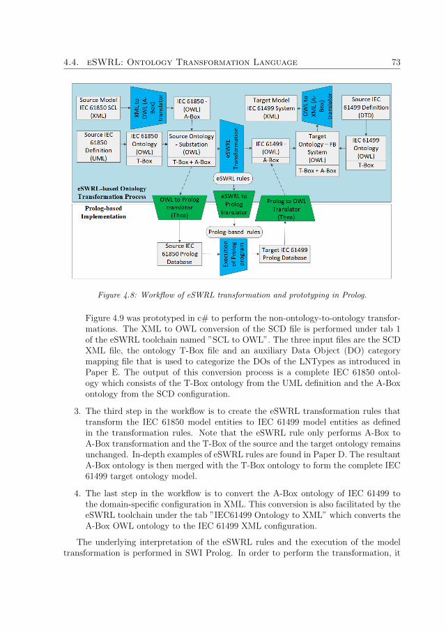
4.4. eSWRL: Ontology Transformation Language 73
Figure 4.8: Workflow of eSWRL transformation and prototyping in Prolog.
Figure 4.9 was prototyped in c# to perform the non-ontology-to-ontology transfor-mations. The XML to OWL conversion of the SCD file is performed under tab 1of the eSWRL toolchain named ”SCL to OWL”. The three input files are the SCDXML file, the ontology T-Box file and an auxiliary Data Object (DO) categorymapping file that is used to categorize the DOs of the LNTypes as introduced inPaper E. The output of this conversion process is a complete IEC 61850 ontol-ogy which consists of the T-Box ontology from the UML definition and the A-Boxontology from the SCD configuration.
3. The third step in the workflow is to create the eSWRL transformation rules thattransform the IEC 61850 model entities to IEC 61499 model entities as definedin the transformation rules. Note that the eSWRL rule only performs A-Box toA-Box transformation and the T-Box of the source and the target ontology remainsunchanged. In-depth examples of eSWRL rules are found in Paper D. The resultantA-Box ontology is then merged with the T-Box ontology to form the complete IEC61499 target ontology model.
4. The last step in the workflow is to convert the A-Box ontology of IEC 61499 tothe domain-specific configuration in XML. This conversion is also facilitated by theeSWRL toolchain under the tab ”IEC61499 Ontology to XML” which converts theA-Box OWL ontology to the IEC 61499 XML configuration.
The underlying interpretation of the eSWRL rules and the execution of the modeltransformation is performed in SWI Prolog. In order to perform the transformation, it

74 Cyber Physical Engineering
Figure 4.9: Prototype of eSWRL transformation implemented in C#.
is necessary to convert the IEC 61850 A-Box ontology to its Prolog representation andvice versa the IEC 61499 Prolog representation to its OWL A-Box representation. Thetransformation between OWL ontology and Prolog is performed in SWI Prolog via theThea library and the reverse transformation is also performed by the Thea library. Theconversion of the eSWRL rules to its Prolog equivalent is assisted by the eSWRL toolchainunder the tab ”eSWRL Rule to Prolog Rule”. Examples of eSWRL transformation rulesand its Prolog representation can be found in Paper D. Although the workflow of theCPE framework consists of an ontology part and a Prolog part, the intention of the CPEframework is that the practitioners will only be working on the ontology level and theunderlying conversion from OWL ontology to Prolog will be handled automatically bythe toolchain.
4.5 Chapter Summary
In this chapter, we formally introduced the CPE framework which leverages the use ofmodel transformation techniques from MDE, semantic web models and domain modelsto automatically generated CPS systems. In particular, we focus on the energy domainwith the aim of automatically generate IEC 61499 distributed automation control systemsfrom IEC 61850 specifications.
Central to the CPE framework is the use and the transformation of OWL ontologymodels and the following contributions were made in this chapter towards implementingthe CPE framework:
1. Conversion of the IEC 61850 UML definition and IEC 61499 DTD definition totheir respective OWL T-Box representations.
2. Development of the ontology transformation language eSWRL, which extends theSWRL OWL reasoning language that permits the creation of class instances andproperties.

4.5. Chapter Summary 75
3. Development of the execution semantics of the eSWRL transformation rules.
4. Development of the eSWRL rule interpreter in Prolog.
5. Development of a set of transformation rules in eSWRL that transforms IEC 61850entities to IEC 61499 entities.
In the current state, we have prototyped a CPE toolchain which performs the variousnon-OWL-to-OWL model conversions with the aim of the eventual integration of theProlog interpreter engine in the toolchain.
In total, there are 4 papers which contribute to the research work in Chapter 4 anda brief summary of the contributions are as follows:
1. Paper B: The ontology transformation language eSWRL is informally introducedin this paper. A simplified OWL model of IEC 61850 and IEC 61499 were we infor-mally introduced and simplified eSWRL transformation rules were demonstratedwith the aim of creating IEC 61499 FBTypes, FBType instances and the logicalconnections between FBType instances.
2. Paper C: A formal graph model of the message passing between LN specificationsis presented and an ontology extension to model this message passing is proposedin this paper to supplement the IEC 61850 ontology with the formal model of themessage passing.
3. Paper D: Paper D introduces the entire eSWRL framework which includes thedefinition of the eSWRL constructs and its Prolog implementation. In addition,the step-by-step workflow of the eSWRL ontology transformation is demonstratedin a case study that model transforms a distributed protection scheme from IEC61850 to an IEC 61499 distributed automation control system.
4. Paper E: Paper E investigates the different types of execution models for eSWRLtransformation and the idea of categorizing DOs of LNTypes was introduced in thispaper which affects the assignments of the DOs as either the input or the outputinterface of its equivalent FBType.
In-depth description of the contribution of each paper can be found in Chapter 7.In the next chapter, we introduce a formal ontological model of functional requirementswhich can be integrated as part of the CPE framework to add control flow to the IEC61499 distributed automation system.

76 Cyber Physical Engineering

Chapter 5
Requirements Modelling
In this chapter, we present a formal ontology that formally models functional require-ments that are modelled in The natural language. The motivation is twofold. The firstmotivation is to address the initial systems engineering design step that is missing inboth IEC 61850 and IEC 61499, which is requirements modelling as outlined in Chap-ter 3.3. The second motivation is to investigate whether functional requirements can beincorporated into the CPE framework to address the lack of control flow in the generatedIEC 61499 distributed automation control system due to the missing relational semanticsbetween the IEC 61850 LNs. This chapter summarizes the contribution of Papers F, Gand H.
5.1 Requirements Modelling in Natural Language
There are several system engineering development models which can be applied whendesign complex industrial automation systems. The waterfall model developed by Royceis a linear development model starting from requirements elicitation, program design,implementation to testing in a top-down design flow from the upper left to the lowerright [54]. The spiral model is a risk-driven development model by Boehm where itera-tive cycles of risk analysis, prototyping and requirement elicitation are evaluated beforereaching the implementation stage [59]. The ”Vee” model [57], a linear model wheredescending the left side of the ”Vee” represents decomposition and definition of the sys-tem while ascending up the other side of the Vee represents the process of integrationand verification. Irrespective of which one of the three models are used, the essentialstarting phases in all these approaches is the elicitation of system requirements at theinitial stage of the development cycle.
Requirements engineering is a structured set of processes and activities with theaim of developing, validating and the maintaining of system requirement documents[121]. System requirements are defined collectively between stakeholders (e.g. the user,customer or developers) to discussed the needs of the system and how these needs can besatisfied [88]. In essence, the agreed upon sets of requirements will identify the behaviour
77

78 Requirements Modelling
and the constraints of the system. In the majority of the project, the stakeholderstypically have a different level of technical knowledge or expertise and it is necessaryto have a mean of documenting and exchanging the defined requirements between allstakeholders in a format which is easily understood.
The definition of Requirement according to the IEEE standard IEEE-STD-1220-2005[122] is as follows:
A statement that identifies a product or process operational, functional, or design char-acteristic or constraint, which is unambiguous, testable or measurable, and necessary forproduct or process acceptability (by consumers or internal quality assurance guidelines).
By this definition, a requirement statement is expected to:
1. Identify a product or process operation, functional, design characteristics or con-straints
2. A statement which is unambiguous, testable or measurable
3. Conforms to product or process acceptability guidelines according to consumers orinternal quality assurance guidelines
Even though there is clear definition of how requirements should be written such asthe one defined by IEEE above, yet it is found that even though the majority of theerrors during system development are found during the software and hardware phases ofthe development cycle, according to past studies in [123], approximately 60 percent of allproject errors originate from incorrect, ambiguous or misinterpreted requirements duringthe design phases. This is problematic and costly as these errors are often detected laterin the development cycle and the costs of fixing these engineering errors rise exponentiallyas the development tends towards the end of the project life cycle [124].
System requirements are normally modelled in NL [125] as it is the most readily un-derstandable means of requirement documentation between the stakeholders. There areadvantages and disadvantages of modelling requirements in NL. Advantages of modellingrequirements in NL includes:
1. Can be written by almost all stakeholders provided the stakeholders have the com-mon language background (E.g. all stakeholders speak and understands English)
2. A valid form of documentation which can be exchanged between the different stake-holders and domain experts in the project.
3. No need to develop proprietary notations between the stakeholders since NL isreadily understandable by humans.
In contrast, there are also disadvantages with modelling requirements in NL whichincludes:

5.2. Formal Modelling of Functional Requirements in Ontology 79
1. Inherent ambiguity in NLs. Vocabularies in NL can have multiple meanings andcan be interpreted in different ways
2. It is an informal modelling language and is therefore not interpretable or processableby machines
One example of an ambiguous NL based functional requirement below:
Transformer TR1 should be tripped during overload currents superior to 120% on anyof its coils that stays for at least 50ms in no more than 100ms.
This functional requirement can be interpreted in two ways. The first interpretationis that the tripping of Transformer TR1 should be completed within 100ms excluding thedetection time of the fault. The second interpretation is that the process of overload de-tection and tripping must all occur within 100ms. These two differences in interpretationcan affect the way in which the control system is implemented.
Formal modelling is one method in which ambiguities in NL requirements can beminimized. As noted by Skekaran et al. [126], the act of requirement elicitation is thegathering of ideas which are inherently informal with the end goal of converting theseideas into, for example, software systems, which is inherently formal. In this chapter, wepropose a formal ontological model that can be used to describe functional requirementswhich firstly, can reduce the ambiguity in the NL representation and secondly, provide ahigh-level abstraction model that can be integrated into the CPE framework. The devel-opment phases that converts an informal NL based functional requirements to a formalrepresentation is shown in Figure 5.1. The first conversion is to convert the informalrepresentation in NL into a semi-formal representation in Restricted Natural Language(RNL). Then, the semi-formal representation is converted to its formal representation inOWL ontology.
Figure 5.1: Development phases of creating a formal requirements ontology from NL.
5.2 Formal Modelling of Functional Requirements in
Ontology
Ontology has been used extensively in software engineering and one example is the Cost-efficient methods and processes for safety-relevant embedded systems (CESAR) [127]

80 Requirements Modelling
reference technology platform which introduce a requirements engineering frameworkthat models requirements using Boilerplates (BP) and domain ontology is used to verifythe correctness of the BP requirements. The CESAR framework semi-automaticallygenerates BP from NL requirements using the DODT [128] tool developed as partof the CESAR project. This semi-automated generation of BPs is assisted by usingdomain ontology which suggests possible attribute values for the BPs based on the definedrelations between the concepts in the domain ontology.
The ontology used in the CESAR framework is a domain ontology, meaning that theontology represents the knowledge of the domain (E.g. an ontology on Smart Grid willrepresent the knowledge about the Smart Grid domain. However, in the context of thiswork, we don’t use the ontology to describe the domain knowledge, but instead, ourproposed ontology describes the structure of the requirement statement itself. To instilstructure into the NL requirements, we use BP, a type of RNL that provides structures inthe construction of requirement statements. BP are predefined statement templates withassignable attributes. The advantages of utilizing BP to model requirement statementsare threefold:
1. BP provides structures to free-text NL requirements which can minimize ambigu-ities and inconsistencies introduced by natural language-based requirement state-ments.
2. It can aid the modelling of various constraints (e.g. performance, capabilities, etc).
3. Since BP is considered to be a semi-formal representation, it is still understandableby stakeholders compared to more formal representations.
The subset of the BP templates shown in Table 5.1 is based on the Easy Approachto Requirements Syntax (EARS) by Mavin et al. [129]. Each BP uses a standard setof structures with placeholders for attributes which are denoted in angle brackets. E.g.〈System〉 or 〈Precondition〉. Take the BP1 template as an example, BP1 models theCondition of the system. The template for BP1 is:
The 〈System〉 is 〈Precondition〉.
Where the 〈System〉 field refers to an entity in the system, I.e. the physical equip-ment in the energy domain and the 〈Precondition〉 field specifies the condition in whichthe BP is invoked. An example of the usage of the Condition BP is as follows:
The 〈Transformer TR1〉 is 〈overloaded by 120%〉.
Where the 〈system〉 field refers to the entity ”Transformer TR1” and the 〈Precondition〉field refers to the precondition ”overloaded by 120%”. For each BP template that isdefined, an FB pattern that can be used to describe the BP in IEC 61499 is ascertained.For BP1, a single FB can be used to model the Condition BP in IEC 61499.

5.2. Formal Modelling of Functional Requirements in Ontology 81
Table 5.1: Boilerplate templates.
Boilerplates DescriptionsFB Pat-terns
BP1The 〈System〉is 〈Precondition〉
ConditionModels the condition of thesystem
BP2The 〈System〉is 〈Function〉
ActionModels the Action of the sys-tem
BP3〈Condition/Action〉is within 〈Quantity〉 〈Unit〉
Performance ConstraintModels the Performance Con-straint of the Action or Con-dition
BP4〈Condition/Action〉is more than 〈Quantity〉〈Unit〉
Timing RequirementModels the Timing Require-ment of the Action or Condi-tion
BP5〈Action〉 WHEN〈Condition〉
Event-DrivenModels the system responsewhen a certain condition ismet
BP6〈Action〉 IF〈Condition〉
Unwanted BehaviourModels the Action of the sys-tem when it encounters an un-desirable condition
BP7〈Action〉 WHILE〈State〉
State-DrivenModels the Action of the sys-tem when it is in a particularstate
BP8〈Condition〉 AND〈Condition〉
AND ConditionModels the AND logic opera-tion when applied to the Con-dition BPs.
BP9〈Condition〉 OR〈Condition〉
OR ConditionModels the OR logic opera-tion when applied to the Con-dition BPs.
BP10〈Action〉 AND〈Action〉
AND ActionModels the AND logic opera-tion when applied to the Ac-tion BPs.
BP11〈Action〉 OR〈Action〉
OR ActionModels the OR logic opera-tion when applied to the Ac-tion BPs.

82 Requirements Modelling
It is worth noting that there are dependencies between BPs due to BP encapsulation.For example, the template of the Event-Driven BP BP5 is:
〈Action〉 WHEN 〈Condition〉.
Where the 〈Action〉 field denotes an Action BP of type BP2 and the 〈Condition〉 fielddenotes a Condition BP of type BP1. For BP5, two FBs are used to model the Event-Driven BP where one FB denotes the Condition and the other denotes the Action. Theencapsulation relationship is reflected in the use of the ”is part of ” prefix in the objectproperty. The subset of the BP templates in Table 5.1 can be categorized into 3 categoriesbased on their level of encapsulation. The first category is the base BPs, which are BPsthat does not encapsulate other BPs. E.g. BP1 and BP2. The second category is theintermediary BPs which can encapsulate other BPs and, can be encapsulated by otherBPs. E.g. BP3, BP4, BP8, BP9, BP10 and BP11. The last category is the top BPswhich encapsulate other BPs and can’t be encapsulated by others. E.g. BP5, BP6 andBP7.
A simplified representation of the BP ontology is shown in Figure 5.2. In total, thereare 10 classes (9 BP class and 1 Requirement class).
The AND/OR in Figure 5.2 denotes two classes, an AND class and an OR class.Therefore, the object property is part of AND/OR also denotes two object propertieswhich are is part of AND and is part of OR. The object property is defined followingthe structure is part of 〈BP〉, where the ”is part of ” prefix denotes that the propertyis of type object property and the 〈BP〉 field defines the target BP in which the sourceBP belongs to. The ”is part of ” prefix is used to model the encapsulation that existsbetween the BPs.
The data properties follow the structure ”has 〈Property〉”, where the ”has ” prefixdenotes the property is of type data property and the ”〈Property〉” field denotes thename of the data property. There are 4 common data properties between all the BPclasses and the data properties are:
1. has boilerplateTypeID: which describes the ID of the BP template as shown incolumn 1 of Table 5.1.
2. has description: which describes the BP instance including its attribute values;
3. has name: which describes the name of the BP instance;
4. has template: which describes the template of the BP as shown in column 2 ofTable 5.1.
In addition, there are also BP type-specific data properties and an example of thedata properties for the Condition BP is shown in Figure 5.3.
The BP specific data properties for the Condition BP are:

5.2. Formal Modelling of Functional Requirements in Ontology 83
Figure 5.2: Simplified ontology showing the is part of 〈BP〉 relationships between the BPs.
Figure 5.3: Data properties of the Condition BP.
1. has systemAttribute: Which describes the system entity that is referenced inthe 〈System〉 field.
2. has preconditionAttribute: Which describes the precondition that is referencedin the 〈Precondition〉 field.

84 Requirements Modelling
5.3 Formalizing Natural Language Requirements to
Ontology
The workflow in formalizing NL requirements to OWL ontology and finally to the IEC61499 control system is shown in Figure 5.4. The conversion of step 1 to step 3 aremanual processes and the last conversion from step 3 to step 4 is automated by the CPEframework.
Figure 5.4: Workflow of formalizing NL requirements to ontology.
The conversion workflow will be illustrated by a running example of the functionalrequirement example used in Paper F. A simple feeder model that is used for this exampleis shown in Figure 5.5.
Figure 5.5: A simple feeder model used by CIGRE B5.02 taskforce for case study.
The functional requirement statement is:
Transformer TR1 should be tripped during overload currents superior to 120% on anyof its coils that stays for at least 50ms in no more than 100ms
As mentioned in Section 5.1, there can be two interpretations of this functional re-quirement. The two possible interpretations as:

5.3. Formalizing Natural Language Requirements to Ontology 85
First Interpretation: The tripping of the TR1 transformer need to be performedwithin 100ms
Second Interpretation: The detection of the overload fault and the tripping of theTR1 transformer need to be performed within 100ms.
For this example, we will model the functional requirement with the first interpreta-tion. The first step in the workflow is to model the NL requirements in the BP templatesfrom Table 5.1. The semi-formal BP models of the functional requirement are shown inListing 5.1.
B2 : The <CT1 on TR1> i s <120% over loaded>B3 : The <CT2 on TR1> i s <120% over loaded>B4 : <B2> OR <B3>B5 : <B4> i s more than <50><ms>B6 : The <BRK1 on TR1> s h a l l <Trip>B7 : The <BRK2 on TR1> s h a l l <Trip>B8 : <B6> i s with in <100><ms>B9 : <B7> i s with in <100><ms>B10 : <B8> OR <B9>B11 : <B10> IF <B5>
Listing 5.1: Semi-formal model of the functional requirements modelled using BPs
The constituents of the functional requirement where each of the BP instance modelsare as follows:
1. B2 and B3: Model the Condition constituent which checks for overload currenton the primary side of the Transformer TR1 (B2) and secondary side of the Trans-former TR1 (B3) respectively.
2. B4: The OR operation is applied over B2 and B3 since the overload only needs tobe active on either on the primary or the secondary side of the transformer.
3. B5: Models the timing constraint constituent which checks to see whether theoverload is active for 50ms.
4. B6 and B7: Models the Action constituent which actuates the Breaker BRK1 onthe primary side of the Transformer (B6) and the Breaker BRK2 on the secondaryside of the Transformer.
5. B8 and B9: Models the timing constraint which states that the tripping of theBreakers on either the primary side of the Transformer (B8) or the secondary sideof the Transformer (B9) must be within 100ms.

86 Requirements Modelling
6. B10: The OR operation is applied since only either the primary or the secondaryside of the Transformer can be tripped at a time.
7. B11: The Unwanted-Behaviour BP is applied to wrap up the Condition con-stituents BP5 and the Action constituents B10.
Note that this is only one potential set of BP instances which can be used to modelthis functional requirement. There are other possible set of BP instances which can beused, and it can affect the structure of the IEC 61499 FB network.
The second step in the workflow is to convert the BP instance set to its ontologicalrepresentation based on the proposed ontology from Figure 5.2. The ontological modelof the functional requirement is shown in Figure 5.6. The bottom-most level are the baseBPs which are the Condition and the Action BPs. The next levels up are the BPs whichencapsulates the Condition and the Action BPs linked by the ”is part of 〈BP〉” objectproperty, where 〈BP〉 denotes the BP that encapsulates it. The Unwanted-Behaviour BPis the top-most BP in this functional requirement.
Figure 5.6: Formal ontological model of functional requirement based on its BP representation.
The implied structure of the BP instances based on the ontological representation isshown in Figure 5.7. Each node represents an FB, the directed arrows are the direction ofthe message passing between the FBs. Black coloured nodes and arcs shows the flatted

5.3. Formalizing Natural Language Requirements to Ontology 87
structures of the BP instances while the greyed dotted rectangular boxes shows theencapsulation BPs. E.g. B4 is the OR BP instance which encapsulates the conditionsB2 and B3. The illustrated structure follows the pattern of Logical Implication suchthat the Condition (Antecedent) appears on the left side of the structure and the Action(Consequent) appears on the right side of the structure. The UnwantedBehavior BPinstance B11 is ”〈B10〉 IF 〈B5〉” where B5 is the antecedent and B10 is the consequent.This is reflected in the structure shown in Figure 5.7 where B5 represents the Preconditionand B10 represents the Action.
Figure 5.7: Visual representation of the implied structure based on the relationships between theBP instances.
The last conversion is the transformation of the requirement ontology model to theIEC 61499 model. This conversion can be performed by the existing CPE framework andthe resultant IEC 61499 FB network is shown in Figure 5.8. There is almost a one-to-one mapping of the entities between the BP instances and the FB instances. The datainterfaces are created based on the values of the optional fields in the BP instances. Forexample, the instance of B2 is:
B2: The 〈CT1 on TR1〉 is 〈120% overloaded〉
The FB which represents the BP B2 in Figure 5.8 is FB1 of type BP1 1. The 2data inputs for the FB is ”CT1 on TR1” and ”Overloaded120Percent” is derived fromthe BP instance B2. In addition, there are also proprietary data interfaces such as the”isOverloaded” data output interface to indicate whether the Condition described by B2is met. Having proprietary data interfaces means that context-specific rules are needed.I.e. dedicated transformation rules for specific functional requirements. The scope ofwhat is generated is currently restricted to the FBTypes, FB instances and the logicalconnections between the FB instances. The internal implementation of each BP instancesis implemented by means of IEC 61850 specification as explored in Paper F and Paper

88 Requirements Modelling
G.
Figure 5.8: FB implementation of the functional requirement.
5.4 Implementation of BP Requirement with IEC
61850 LN Specifications
This section presents two methods of implementing the functional requirements BPs bymeans of IEC 61850 specifications in the IEC 61499 automation control system. Thefirst method is to implement the IEC 61850 specifications within the requirement BPFBs and the second method is to implement the IEC 61850 specifications as Services.
The first method is shown in Figure 5.9. The abstract implementation of method 1is shown in Figure 5.9a where the BP requirements are implemented as composite FBs.Composite FBs are a type of FB in IEC 61499 that can encapsulate an FB network.The FB network that is encapsulated within the BP requirement FB is the IEC 61850specification that implements the behaviour of the BP. An example of this implementationis shown in Figure 42b, where FB1 of FBType BP1 1 represents the BP instance B2from Listing 1. To implement this BP, two IEC 61850 LN specifications, the CurrentTransformer LN TCTR and the Instantaneous Overcurrent LN PIOC are used. The LNspecifications can either be auto-generated as part of the CPE framework or instantiatedfrom a set of LN libraries. The advantages of implementing the LN specifications ascomposite include:
1. Ease of Tracing: It is straightforward to trace the specifications that implementthe BP since the specifications are implemented within the BP Composite FB.
2. Ease of Testing: Black-box testing can be applied to test whether the imple-mented specifications meet the desired behaviour set by the BP requirement.
The disadvantages of implementing the LN specifications as composites include:
1. Rigidness in Implementation: In order to implement BP as Composite FB,it is necessary to create a Composite FBType. This means all instances of thisComposite type will have the exact same implementation and this may not alwaysbe desirable.

5.4. Implementation of BP Requirement with IEC 61850 LNSpecifications 89
(a) Abstract view of the Composite Imple-mentation
(b) FB view of the Composite Implemen-tation
Figure 5.9: Composite implementation in abstract and FB form
2. Duplication of LN in Implementation: There are cases where a mismatch ofLN instances between the SCL definition and the FB implementation can occur ifmultiple functional requirements reference the same LN instance in the SCL. E.g. ifmultiple requirements actuate the same Circuit Breaker, each Composite FBTypewill have an instance of the Circuit Breaker LN while the SCL may only have 1 LNinstance for that Circuit Breaker in its configuration.
The second method is shown in Figure 5.10. The abstract implementation of method2 is shown in Figure 5.10a where the BP requirements are modelled as FBs just likemethod 1. However, the LN specifications are modelled as self-contained Services intheir own FBs with a dedicated communication channel established between the BP FBand the Service FB. This architecture is based on the interactive relationship betweenthe Services and the Orchestrator in Service Oriented Architecture (SOA) where the Or-chestrator defines the control flow of the system and the Services provides the necessaryfunctionality for the Orchestrator at each state of the control flow. An example of anFB implementation of method 2 is shown in Figure 5.10b. FB31 and FB32 are bothparts of a functional requirement where the requirement for FB31 is to retrieve a sampleof the Current measurement and the requirement of FB32 is to check whether the Cur-rent sample is overloaded. The LN specification which fulfils the requirement of FB31is the Current Transformer TCTR and its implementation as a Service is illustrated asFB34. In this example, a single LN specification is able to fulfil the requirement, butit is also possible to have Composite Service where multiple LN specifications imple-ment the Service. The dedicated communication channel between FB31 and FB34 is atwo-way channel where the requirement FB FB31 requests for Service via the interface(REQUEST Msg → REQUEST Message) and the Service FB FB34 responds via theinterface (RESPONSE Message → RESPONSE Msg).
The advantages of implementing the LN specifications as Services include:
1. De-coupling of Requirement and Service: There is flexibility in the imple-

90 Requirements Modelling
(a) Abstract view of the SOA Implementa-tion (b) FB view of the SOA Implementation
Figure 5.10: SOA implementation in abstract and FB form
mentation of the requirement since the implementation is now decoupled from therequirement. This separation of the requirement BP from the implementation en-sures that Services can be modified without impacting on the requirement it fulfils.
The disadvantages of implementing the LN specifications as Services include:
1. Increased Communication Overhead: Since a dedicated communication chan-nel is now necessary for every Requirement BP and Service pair, the communicationoverhead is increased in the control system.
2. Increased Computation: In the current implementation, the messaging protocolbetween the requirement BP and the Services are embedded as strings which consistof the request message and the data. Therefore, it is necessary for the Service toperform both Syntactic and Semantic validation of the request message and viceversa when the response message is created.
There is no preferred method of implementation since both methods present distinctadvantages and at the same time, clear disadvantages. The utilization should be based onthe design intent of the control system. For example, if the aim is to have a control systemwhich can be tested, then method 1 might be the preferred implementation. However,if the aim is to have a control system which is flexible, then method 2 might be moresuitable.
5.5 Chapter Summary
In this chapter, we proposed a formal ontological model for the purpose of modellinginformal NL based functional requirements. The aim of the formal model is to firstly,mitigate the ambiguities of NL based functional requirements and secondly, to ascertain

5.5. Chapter Summary 91
the control flow of the control system based on the described behaviour in the func-tional requirement with the aid of intermediary semi-formal BP models. The followingcontributions were made in this chapter:
1. Introduced a subset of semi-formal BP templates that can be used to model func-tional requirements in the context of the energy domain.
2. Identified equivalent FB patterns based on the BP templates.
3. Explored two methods in which BP requirements and IEC 61850 LN specificationscan be implemented in IEC 61499 where the BP specifies the required behaviourand the LN specifications implement the said behaviour.
In total, there are 3 papers which contribute to the research work in Chapter 5 andthe contributions are as follows:
1. Paper F: In this paper, the initial investigation in the use of an ontological model toformally model the implied structure described in the functional requirement is car-ried out. The ontology used in this paper is a simplified ontology and demonstrateshow the functional requirement can be represented in the IEC 61499 automationcontrol system.
2. Paper G: In this paper, we explore the use of a design pattern based on the rela-tionships between Services and Orchestrators in SOA architecture to create an IEC61499 automation control system which is flexible and adaptable to change in eitherthe requirement or the specification. The idea is to implement LN specifications asServices and the functional requirements as Orchestrators in order to decouple therequirements from the specification to create a flexible automation control system.
3. Paper H: In this paper, we introduce the formalization of NL requirements toontology with the aid of BP templates. In addition, a case study example is showndemonstrating how the informal NL language requirement can be converted to anIEC 61499 automation control with the aid of the BP and the ontology model.
An in-depth description of the contribution of these three papers can be found inChapter 7. In the next chapter, we identify various potential testing methodologieswhich can be used to validate and verify different aspects of the IEC 61499 distributedautomation system.

92 Requirements Modelling

Chapter 6
Testing and Validation
In this chapter, we present an automated script based co-simulation framework thatcan be used to test the generated control system against the system requirement. Theco-simulation framework is an event-driven approach that leverage two heterogeneoussimulation platform interfaced via a common communication channel. The appendedpaper which contributes to this Chapter is paper I.
6.1 Validation of Functional Requirement
In the domain of software engineering, there are two approaches for software testingwhich are software validation and software verification. The purpose of these two typesof testing approaches are:
1. Software Validation: To check whether the right control system is built. Soft-ware validation is performed using black-box testing with the purpose of testingwhether the behaviour of the control system fulfils the system requirements andspecifications irrespective of the internal implementation of the control system.
2. Software Verification: To check whether the system is built right. Software ver-ification is performed using white-box testing with the purpose of testing whetherthe internal implementation of the control system is correct.
Black-box testing, otherwise known as behavioural testing is typically used to test thebehaviour of the system which can be both non-functional and functional, although it ismost often used to test for functional behaviour of the system. The testing procedure ofBlack-box testing is shown in Figure 6.1. The system that is being tested is treated likea black-box where the internal implementation of the system is unknown to the tester.The testing procedure starts with a set of inputs that is injected into the system and theoutput is observed to see whether the expected output is produced by the system.
Take the functional requirement in Chapter 5 as an example. The functional require-ment is:
93

94 Testing and Validation
Figure 6.1: Procedure of black-box testing.
Transformer TR1 should be tripped during overload currents superior to 120% on anyof its coils that stays for at least 50ms in no more than 100ms.
One of the test scenarios that can be used to test for the behaviour of the system withrespect to the functional requirement is as follows: ”An overload current is detected onthe primary side of TR1 that persists for more than 50ms. The breaker BRK1 actuatesto clear this overload current.”
A set of potential input and output variables to test for this scenario is as follows:The use of the variable names is based on Figure 5.5:
1. Inputs: The set of input values that is inserted into the system are:
(a) Input 1: An overload current ICT1 that exceeds 120% of the coil reading onthe primary side of TR1 is inserted into the system.
(b) Input 2: A non-overload current ICT2 on the secondary side of TR1 is insertedinto the system.
2. Outputs: The set of expected output values are:
(a) Output 1: The time output tFaultActive should be more than 50ms to showthat the fault was active for more than 50ms
(b) Output 2: The trip output TBRK1 is set to TRUE to trip the BRK1 breakeron the primary side of TR1
(c) Output 3: The time output tTripPrimary should be less than 100ms to showthat the tripping took less than 100ms to complete
6.2 Automated Script based Co-Simulation Frame-
work
The automated script based co-simulation framework is an extension to the event-drivenco-simulation framework by Zhabelova et al. [30] and Yang et al. [94] by automat-ing the simulation process with Matlab scripts. The architecture of the scripted basedco-simulation framework is shown in Figure 6.2. The co-simulation framework is aheterogeneous simulation platform that integrates a power system simulator (MATLAB

6.2. Automated Script based Co-Simulation Framework 95
Simulink) and a distributed control platform developed in an IEC 61499 Integrated De-velopment Environment (IDE). The two simulation platforms are interfaced through anEthernet communication channel utilizing the User Datagram Protocol (UDP) proto-col. The process of the co-simulation framework is triggered by the simulation plant(The sampling rate of the measurement readings) and the simulation control reacts tothe sampled measurement readings and sends actuating signals back to the simulationplant if necessary. The role of the Matlab script is to automate the co-simulation processthrough N iterations.
Figure 6.2: Architecture of the script based Co-simulation framework.
The workflow of the automated script based co-simulation platform is shown in Fig-ure 6.3. Firstly, a set of input and output variables that is to be observed is defined inthe Matlab workspace. Secondly, the Matlab script initialises the both of the simula-tors to their respective initial states. Thirdly, the power system simulator is set to startand begins to send measurement data to the control simulator. Fourthly, the simulatordata that are defined in step 1 are collated during the simulation of the test scenario.This means at each sampling rate, there will be a set of input and output data that isrecorded. lastly, the simulators are reset by the Matlab script and the simulation scenariois iterated through N iterations. Note that the ending of a simulation run can be set bydefining an ending state of the simulation. For example, with respect to the functionalrequirement in Section 6.1, if the test scenario is to test the time tTripPrimary it takes forthe trip signal TBRK1 to be set to true after an overloaded is detected, the end pointof the simulation can either be set to the time the TBRK1 becomes TRUE or pre-set aperiod of time in which the simulation scenario is expected to last.
The automated scripted based co-simulation platform was used in Paper I to analysethe performance of Fault Location and Isolation (FLI) for primary power distributionfeeders using wireless networked sensing and control. The objective was to analyze theeffect of the reliability of the communication network on the time required for the overallsystem to locate and isolate the fault and inform the substation of the fault location.
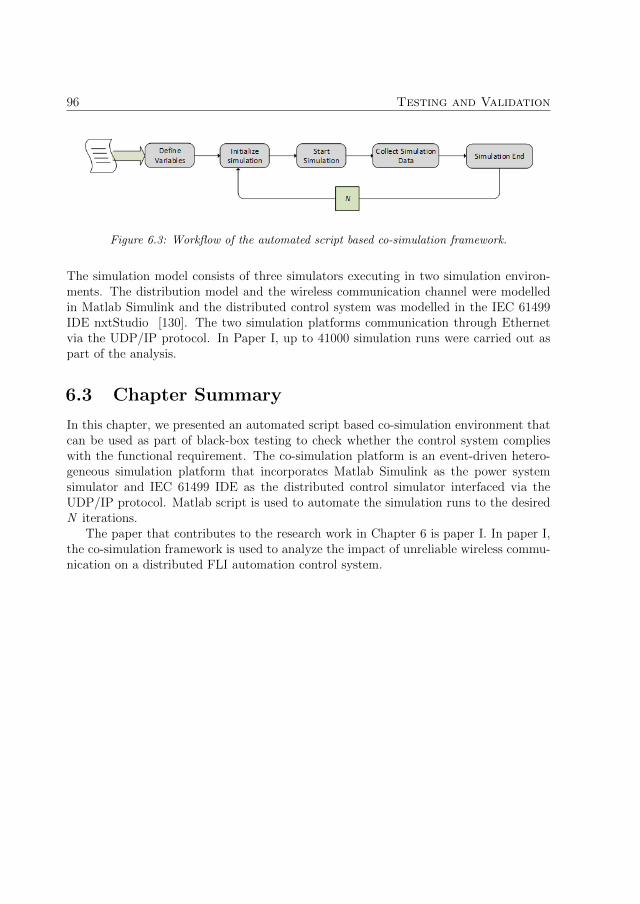
96 Testing and Validation
Figure 6.3: Workflow of the automated script based co-simulation framework.
The simulation model consists of three simulators executing in two simulation environ-ments. The distribution model and the wireless communication channel were modelledin Matlab Simulink and the distributed control system was modelled in the IEC 61499IDE nxtStudio [130]. The two simulation platforms communication through Ethernetvia the UDP/IP protocol. In Paper I, up to 41000 simulation runs were carried out aspart of the analysis.
6.3 Chapter Summary
In this chapter, we presented an automated script based co-simulation environment thatcan be used as part of black-box testing to check whether the control system complieswith the functional requirement. The co-simulation platform is an event-driven hetero-geneous simulation platform that incorporates Matlab Simulink as the power systemsimulator and IEC 61499 IDE as the distributed control simulator interfaced via theUDP/IP protocol. Matlab script is used to automate the simulation runs to the desiredN iterations.
The paper that contributes to the research work in Chapter 6 is paper I. In paper I,the co-simulation framework is used to analyze the impact of unreliable wireless commu-nication on a distributed FLI automation control system.

Chapter 7
Contributions
This chapter summarizes the appended papers and my contributions to each paper.In total, there are two published and peer-reviewed IEEE Transactions papers (PaperD and Paper I), one submitted IEEE Transactions paper (Paper H), five published andpeer-reviewed IEEE international conferences (Paper B, Paper C, Paper E, Paper Fand Paper G) and lastly, one published and peer-reviewed open access EAI endorsedtransactions paper (Paper A).
7.1 Paper A
Title: SysGRID: IEC 61850 and IEC 61499 Standard Based Engineering Tool for SmartGrid Automation DesignAuthors: Chen-Wei Yang, Gulnara Zhabelova, Valeriy VyatkinPublished in: EAI Endorsed Transactions on Energy Web, 2014Summary: This paper demonstrates the synergies and similarities of the two industrialstandards, IEC 61850 and IEC 61499 from the perspective of systems engineering. Bothstandards utilize the top-down design approach (a design paradigm where the systemis first designed as a whole before distributing the system to individual hardware con-trollers) in designing distributed systems in their respective domains. This paper showsthat specification is the first step of the design process in both standards. IEC 61850utilizes the single line diagrams (SLD) as the specification for the physical layout of thesubstation and the concept of Logical Nodes for physical and functional specifications.IEC 61499, which is also known as an action specification, models the abstract levelspecification with the Function Block artefacts which can then be used to implement andsimulate the specification. The paper also shows the extent to which an IEC 61499 canbe auto-generated from IEC 61850 specifications and also highlights the limitations ofusing IEC 61850 as the source model for auto-generation. The paper also shows howco-simulation verification can be achieved demonstrated on a case study.Contribution: I participated in the discussion of the synergies of the two standardsand conducted the case study co-simulation which includes designing the MATLAB sim-
97

98 Contributions
ulation model, designing and implementing the IEC 61499 control model and doing thesimulation to obtain the resultant graphs.Relevance: This paper addresses research question one.
7.2 Paper B
Title: On automatic generation of IEC61850/IEC61499 substation automation systemsenabled by ontologyAuthors: Chen-Wei Yang, Valeriy Vyatkin, Arash Mousavi, Victor DubininPublished in: IECON 2014 - 40th Annual Conference of the IEEE Industrial Electronics2014, Dallas, TX, USASummary: This paper informally introduces the eSWRL transformation language forontology-based MDE. The paper describes how IEC 61850 and IEC 61499 can be utilizedin an ontology-based model transformation. The paper presents IEC 61850 specificationas the source model for model generation and IEC 61499 as the target model of themodel generation. The concept introduced in that paper was demonstrated in a simplecase study. The case study was a simple overcurrent protection system where a simplifiedversion of the IEC 61850 ontology was first developed from the IEC 61850 Logical Nodespecification. Then examples of the eSWRL transformation language that can be used toauto-generate IEC 61499 Function Blocks from IEC 61850 Logical Node specifications.This paper also introduces the concept of category-based designations of LN data objectsas either FB data inputs or data outputs, which differs from the intelligent LogicalNode concept where LN data objects are assigned as both inputs data and output data.The result demonstrates how model transformation rules can be written in a declarativelanguage.Contribution: I formulated the category based designation of the data objects as datainput or outputs. I also participated in the development of the case study, which includesdesigning the IEC 61850 SCL model, the simplified IEC 61850 ontology model and theformulation of the transformation rules.Relevance: This paper contributes to addressing research question two.
7.3 Paper C
Title: Modelling of IEC 61850 Message Passing for Automatic Generation of DistributedControlAuthors: Chen-Wei Yang, Valeriy VyatkinPublished in: 41st Annual Conference of the IEEE Industrial Electronics 2015, Yoko-hama, JapanSummary: This paper introduces a graph based representation of the message passingto the Logical Node specifications which aim to address one of the limitations identifiedin Paper A, which is the lack of semantic relationships between the LNs. This paper firstmodels the message passing in a graph where the LNs are modelled as vertices and the

7.4. Paper D 99
messages are modelled as edges. This graph representation is then converted to an ontol-ogy representation to be used as a part of the ontology MDE framework. The ontologyextension proposed in this paper supplements the IEC 61850 ontology model in PaperD to model the semantics and the interconnections between the LNs. This paper alsointroduces the DTD based IEC 61499 ontology model and a set of transformation ruleswere shown to demonstrate how the proposed ontology extension can be used to createthe logical connections between the Function Blocks in the IEC 61499 application.Contribution: I formulated the graph model of the message passing and the ontologyextension which models the graph. I also developed the DTD based IEC 61499 ontologymodel and wrote the transformation rules to demonstrate the transformation.Relevance: This paper contributes to addressing research question two.
7.4 Paper D
Title: Ontology Driven Approach to Generate Distributed Automation Control fromSubstation Automation DesignAuthors: Chen-Wei Yang, Victor Dubinin, Valeriy VyatkinPublished in: IEEE Transactions on Industrial Informatics, Volume 13, Issue 2, April2017Summary: This paper introduces ontology-based MDE framework. The novel conceptintroduced in this paper includes the set of eSWRL constructs which were introducedto enable ontology-based model transformation and the definition of these constructs inProlog. The full model transformation process was demonstrated in a case study. Thecase study is a power distribution system running de-centralized protection automationsystem. The case study demonstrates the design process which includes first developingthe IEC 61850 SCD XML model, then mapping the XML model to its ontology model.The IEC 61850 ontology model is then transformed using the transformation rules de-veloped in eSWRL to a resultant IEC 61499 ontology model. The IEC 61499 ontologymodel was then mapped to its IEC 61499 XML representation. This paper reveals theprocess of developing the declarative transformations rules and the mapping of the rulesfrom eSWRL to its Prolog implementation.Contribution: I participated in the formulation of the framework. In addition, I de-veloped the case study model, the IEC 61850 SCD XML model, the IEC 61850 andIEC 61499 ontology models, all the transformation rules and the mappings between theXML and the ontology models. I also developed a software design tool called ”eSWRLToolchain” which automates most of the design process described in this paper.Relevance: This paper contributes to addressing research question two and is a followup of the initial study from Paper B and C.

100 Contributions
7.5 Paper E
Title: On Development of Execution Model for Model Transforming Distributed Sub-station Automation Control with OntologyAuthors: Chen-Wei Yang, Valeriy Vyatkin, Victor DubininPublished in: ISIE 2017 IEEE 26th International Symposium on Industrial Electronics,Edinburgh, UKSummary: In this paper, we investigate a set of possible execution models that is mostsuitable to be implemented in the context of the model transformation of IEC 61850models to IEC 61499. Several execution models were discussed and the most suitableexecution model was found to be the Single Pass Iterative Execution (SPIE) model. Thisis due to the composite structure that exists in both IEC 61850 and IEC 61499 models forwhich the SPIE was found to be the most suitable. And an example of the transformationrules written for the SPIE execution model was demonstrated to show how IEC 61850specifications are transformed to IEC 61499 FBs with a high level of encapsulation.Contribution: I participated in the formulation and the selection of the executionmodels. I developed the visual mapping and the transformation rules for the case studyexample. Relevance: This paper contributes to addressing research question two andis a follow up of the initial study from Paper C.
7.6 Paper F
Title: On Requirements-Driven Design of Distributed Smart Grid Automation ControlAuthors: Chen-Wei Yang, Valeriy VyatkinPublished in: INDIN 2017 IEEE 15th International Conference on Industrial Informat-ics, Emden, GermanySummary: In this paper, we investigate and attempt to address one of the limitationsidentified in paper A, which is the lack of a means to model requirements in IEC 61850and, in addition, can also address the semantic issues. The paper explores how functionalrequirements can be modelled formally in IEC 61499 with the aid of ontology models. Thenovel concept introduced in this paper is an ontology model which describes the structureof requirement statements rather than an ontology which describes the domain. The aimof the ontology model is to ascertain structures within the requirement statement whichcan then be broken down into constituent parts and modelled as FBs. The case studyscenario and the sets of requirements were obtained from the CIGRE council. Formalmodels in the ontology were developed to illustrate how it can be translated to an IEC61499 representation. Then, a small test case was investigated to show how black-boxtesting can be applied in IEC 61499 to test the behaviour the implemented requirements.Contribution: I developed the ontology models and conducted the case study whichdemonstrates how functional requirements can be modelled in ontology and IEC 61499.I also conducted the black-box testing of the requirement.Relevance: This paper contributes to addressing research question three.
7.7. Paper G 101
7.7 Paper G
Title: Service-oriented Extension of IEC 61850 for Model-Driven Smart Grid Automa-tion DesignAuthors: Chen-Wei Yang, Valeriy Vyatkin, Cheng PangPublished in: IECON 2017 43rd Annual Conference of the IEEE Industrial Electronics2017, Beijing, ChinaSummary: In this paper, we again explore the idea of how to model requirements for-mally in IEC 61499 to address the limitations found in Paper A. This paper investigatesthe use of a design pattern based on Service-Oriented Architecture to create an IEC61499 automation control system which is flexible and adaptable to change in either therequirement or the specification. The specific relationship that is of interest is the re-lationship between the orchestrator and services, where the orchestrator can representthe functional requirements and the services can represent the IEC 61850 specifications.This design pattern leverages the relationships between the orchestrator and the serviceswhich induce decoupling between the requirements and the specifications in the controlsystem. The case study is used to demonstrate the process the design process startingfrom the requirement stage to the end control system. The design process is based onthe use of use-case diagrams which identifies actors within a requirement. Each actoridentified in the use-case diagram is then modelled as an orchestrator actor and eachorchestrator actor is then connected to a set of FBs which implements the specificationsfor the actor.Contribution: I developed the idea of applying the SOA based design pattern formodelling functional requirements in IEC 61499. I also developed the case study whichincludes defining the interfaces of the services, the orchestrators, implementation of theFBs and the black-box testing.Relevance: This paper contributes to addressing research question three and is an ex-tension of the work in Paper F.
7.8 Paper H
Title: Model Driven-by-Requirements Approach to Automatically Generate Smart GridCyber-Physical SystemsAuthors: Chen-Wei Yang, Victor Dubinin, Valeriy VyatkinSubmitted to: IEEE Transactions on Industrial InformaticsSummary: This paper is a follow up to the initial study of formally modelling require-ments in IEC 61499 conducted in Paper F and Paper G. This paper introduces the useof the semi-formal boilerplate models as the intermediary model to add structure to theinformal natural language based requirement statements. The boilerplate model is thenmapped to an ontology model, which was also developed in this paper with the aim ofmodelling the structure of the boilerplate statements. The proposed formal requirementmodelling methodology was demonstrated in a case study. The case study distributionsystem and its functional requirements were obtained from the CIGRE taskforce group

102 Contributions
B5.02. The informal functional requirement in natural language was first modelled in thesemi-formal boilerplates. The boilerplate model was then formally modelled in ontologybefore eSWRL based ontology model transformation was applied to demonstrate howrequirements can be automatically generated and represented in IEC 61499.Contribution: I proposed the idea of introducing an intermediary boilerplate modelto requirement modelling and derived the FB pattern for each boilerplate template. Ideveloped the case study system which includes the modelling of the requirement in boil-erplates, in ontology and the eSWRL transformation rules.Relevance: This paper contributes to addressing research question three and is an ex-tension of the work in Paper F and Paper G.
7.9 Paper I
Title: Automated Fault Location and Isolation in Distribution Grids with DistributedControl and Unreliable CommunicationAuthors: Neelabh Kashyap, Chen-Wei Yang, Seppo Sierla, Paul G. FlikkemaPublished in: IEEE Transactions on Industrial Electronics, Volume 62, Issue 4, April2015Summary: In this paper, we explore the effect unreliable communication has on dis-tributed substation automation control system such as the FLI (Fault Location and Iso-lation) protection scheme. In this paper, we employed a hybrid co-simulation frameworkmade up of three models executing in parallel. The simulation of the distribution modelwas modelled in MATLAB Simulink. The FLI distributed control was modelled in IEC61499 and the abstract wireless communication model was again modelled in MATLAB.Script based co-simulation testing was employed which allowed us to automatically iter-ate the number of simulation runs (up to 41000 simulation runs) to obtain a large samplesize to derive relevant results. This paper shows how script based iterative co-simulationcan be used to verify the correctness of the automatically generated control system.Contribution: I contributed to the formulation of the FLI control algorithm used inthis paper and the setup of the co-simulation framework that is used for the case study.I developed the IEC 61499 control system and interfaced the IEC 61499 developmentplatform (NxtStudio) with MATLAB Simulink.Relevance: This paper contributes to addressing research question four.

Chapter 8
Conclusions and Future Work
The aim of the research work presented in this thesis was to investigate how a top-down design framework for the engineering of Cyber-Physical Systems that leverages theuse of model-driven design techniques, semantic web models and distributed software ar-chitectures could be developed. The target domain is the energy domain and the goal ofthe Cyber-Physical Engineering framework is to automatically generate distributed sub-station automation control system from substation specifications and functional require-ments. The substation specifications include the specifications of the physical structure,the communication network, the device configurations and the data models, of which aremodelled using IEC 61850, which standardises the communication networks and systemsfor power utility automation. The distributed automation control is implemented in theexecutable specification language IEC 61499 which provides a reference architecture forthe design of distributed industrial automation systems. Efforts towards realizing theCPE framework must first overcome design challenges associated with ontology transfor-mation and the formalization of the functional requirements. With regards to ontologytransformation, the first design challenge is the restriction that is placed on existingontology reasoning language which does not allow model transformation. Therefore, atransformation language for transforming ontology needed to be introduced. The seconddesign challenge is related to the first design challenge where a complimentary modeltransformation interpretation engine needed to be developed to interpret the introducedtransformation language and to perform the transformation. With regards to the formal-ization of functional requirements, it was necessary to investigate how natural languagebased functional requirements could be formalized and synthesized in IEC 61499 in orderto dictate the control flow of the distributed automation control system.
8.1 Conclusions
At the beginning of the thesis, 4 research questions were posed and the results whichcontribute towards answering these 4 research questions are:
Q1: To what extent can a distributed substation automation software system be auto-
103

104 Conclusions and Future Work
matically generated with MDE techniques by leveraging the industrial standardsIEC 61850 and IEC 61499? What is missing and what more is needed to automat-ically generate a software automation system that complies with top-down designapproaches.
The initial investigation into the capabilities of the two industrial standards IEC61850 and IEC 61499 from the perspective of systems engineering and Model-Driven Engineering was carried out in Paper A. To assess the extent in which wecan use model transformation technique from MDE to auto-generate an IEC 61499distributed automation control system, the recommended IEC 61850 SCL config-uration to be used is the Substation Configuration Description configuration as itcontains the complete configuration for an IEC 61850 substation automation sys-tem. An IEC 61499 FB type library can be generated from the DataTypeTemplatessection of the SCD configuration. However, the DataTypeTemplates definition isonly sufficient to the generate the interfaces of the FB type and the internal imple-mentation of the ECC and the algorithms can’t be generated. The assignment ofthe LN type Data Object as either the input or the output interface of the Func-tion Block type is based on the categorization of the Data Objects introduced inPaper B. An IEC 61499 Application can be generated from the configuration ofthe Substation section of the SCD. What is generated in the Application is the FBinstances, but not the logical connections between the FB instances. IEC 61499device instances can be generated from the IED section of the SCD configura-tion which includes the mapping of the FB instances from the Application to theDevices. The communication configuration for the IEC 61499 devices can be gener-ated from the Communication section of the SCD configuration. The two missingcomponents that can’t be auto-generated are firstly, the internal implementationof the FB types and secondly, the logical connections between the FB instances inthe Application. Essentially, the scope of an IEC 61499 control system in whichthat can be auto-generated from IEC 61850 SCD specification is the structure ofthe control system, but not the functional implementation and the control flow.Top-down design is just one of the Systems Engineering approach for the designof systems which are distributed. From the perspective of IEC 61850 and IEC61499, the first step of the design stage for both standards is the specification stageand both lack the mean to model requirements. Formal modelling of functionalrequirements could address the limitation with control flow, but there are still a lotof research work that needs to be done to make this a viable solution.
Q2: What are the fundamental principles behind a possible MDE automatic generationframework that leverages the use of knowledge bases such as ontological models?
The principle of MDE approach is to leverage the use of formal models throughoutthe design process of the system from the initial requirements and specificationsto platform control. The design process is aided by the iterative enhancement

8.1. Conclusions 105
of models through model transformation. In the context of substation automa-tion in this thesis, we took inspiration from the design approach of MDE and thetype of models that are leveraged through the model transformation process arethe domain-specific models and the domain-neutral models. The domain-specificmodels are the IEC 61850 and the IEC 61499 XML configuration models and thedomain-neutral models are the semantic web ontological models. The three fun-damental components which are needed to enable model transformation are firstly,a formal model, secondly, a model transformation language and lastly, a trans-formation engine that interprets the transformation rules and performs the modeltransformation. The domain-neutral formal model used is ontology model devel-oped using the OWL programming language. The T-Fox ontology model of IEC61850 was developed based on its UML definition and the T-Box ontology modelof IEC 61499 was developed based on its DTD definition. The transformationlanguage is called eSWRL, which is an extension to the OWL reasoning languageSWRL. eSWRL retains the majority of the syntax in SWRL with added constructsto create Class instances and property assertions. The initial investigation of usingeSWRL for transformation ontology model in the energy domain was carried out inPaper B and the use of a standard IEC 61499 DTD ontology for model transforma-tion was used in Paper C. The transformation engine was developed in SWI Prologand this meant the eSWRL transformation rules and the OWL ontological modelswere automatically converted to Prolog where the model transformation took place.The formal definition of the eSWRL transformation construct in Prolog is outlinedin Paper D. In Paper E, the development of the execution model of the transforma-tion rules is discussed. The development of this framework was essential and formsthe backbone of the CPE framework. The viability of the framework was shown ina case study in Paper D where it was shown that an IEC 61499 control structurecan be demonstrated from IEC 61850 with OWL models and declarative transfor-mation rules. The prototyping tool ”eSWRL Toolchain” was also developed in partto assist with the non-ontology-to-ontology transformation in the framework.
Q3: To what extent can formal modelling of functional requirements assists in automat-ically generating an IEC 61499 automation software system with control flow?
An ontological model was proposed for the purpose of formally modelling the func-tional requirements in natural language. The conversion from an informal NLfunctional requirement to the formal OWL model is aided by the semi-formal boil-erplates which were used to create structure in the NL functional requirement.Based on the formal model of the structure obtained from the boilerplate model,control flow in IEC 61499 could be created. Paper H outlines this conversion pro-cess and a case study example is used to illustrate how the proposed method canbe used to create control flow in IEC 61499 from formal functional requirements.Two methods of representing the interactions between the control flow derived fromfunctional requirements and the IEC 61850 specification were explored in Paper G

106 Conclusions and Future Work
and Paper H. Paper G presents the Composition method which encapsulates theimplementation of the IEC 61850 specification in the requirement FB. Paper Hpresents the Service Oriented Architecture inspired method which implements theIEC 61850 specifications as services and the interactions between the requirementboilerplates and the services are achieved via dedicated communication channels.This methodology has only been tested on a subset of functional requirements sothe sample size is still relatively small. It is necessary to test this on a larger setof functional requirements. In addition, further investigation into the two methodsin modelling the interactions between the requirements and the IEC 61850 specifi-cations in IEC 61499 need to be carried out to address the disadvantages of eachmethod to truly evaluate the viability of this approach in creating control flow fromfunctional requirements.
Q4: How the compliance of the generated system with the requirements could be effi-ciently and rigorously validated?
There are different types of validation and verification techniques that can be ap-plied to check the correctness of the generated IEC 61499 control system. Ontologyand Prolog reasoning can be applied to check for the structural correctness of theIEC 61499 control system. Formal methods such as model checking can be used tocheck for the correctness in the implementation of the IEC 61499 control system.In the context of requirement testing, the traditional method of testing the imple-mentation of the control system against the requirement is to perform black-boxtesting. We use a similar approach but instead of performing black-box testing ofindividual devices and only test the implementation at the local level. We performautomated iterative co-simulation to firstly, test the global behaviour of the imple-mentation against the requirement and secondly, to test whether the behaviour ofthe implementation is deterministic (I.e. the same result is obtained after multipleiterations). Paper I demonstrates the usage of the automated script based iterativeco-simulation environment for the testing of a simple Fault Location and Isolationcontrol system implemented in IEC 61499 under unreliable communication. Theplant model and the unreliable communication channel were simulated in MatlabSimulink and the Fault Location and Isolation control were implemented in IEC61499. A script written in Matlab was used to iterate the co-simulation test up to41000 simulation runs. The next step is to utilize this same testing approach ona much more complicated control system such as the distributed Fault Location,Isolation and Service Restoration control system.
8.2 Future Work
The initial proposal of the CPE framework was to automatically generate both the dis-tributed control system and the simulation plant model. The scope of the research workwas restricted to the research challenges presented in the automatic generation of the

8.2. Future Work 107
control system only due to the need to also develop the ontology transformation lan-guage and the transformation engine. The next step in the development of the CPEframework in the context of the energy domain is to investigate how the simulation plantmodel can be automatically generated from IEC 61850 specifications. Inspiration canbe taken from the research work by Voinov et al. [131] which utilizes the Substationsection of the SCD configuration to automatically generate the Supervisory Control andData Acquisition (SCADA) Human Machine Interface (HMI). However, in order to au-tomatically generate the simulation plant model in MATLAB Simulink as part of theautomated Co-simulation framework, the integration of the CIM models to IEC 61850specification would be beneficial as the CIM standards, specifically IEC 61970-301 [132]provide semantic model that can supplement the IEC 61850 Substation description toprovide the relational semantics between the substation components.
One of the limitations of the current approach is that based on the DataTypeTem-plates section of the SCD file, it is only possible to generate the interfaces of the FBtype in IEC 61499. However, it is not always the case that it is necessary to generateFB types during every model transformation. IEEE C37.2 standardizes a set of functionnumbers and acronyms for functions used in electrical substations [133] with recommen-dations of IEC 61850 LN specifications that can be used to implement the standardizedfunctions. Therefore, it is possible to create a library of functions in IEC 61499 withvarying interfaces and ontological reasoning can be applied to the requirements Ontologyto select the most suitable functions for each requirement boilerplates. Alternatively, bystandardizing the protection functions and schemes based on the configuration of thesubstation or bays [134] as scoped by the CIGRE B5.27 working group, the substationautomation control system can also be automatically generated based on the reasoningof the Substation section of the IEC 61850 SCD configuration.
The testing methods introduced in this thesis is based on automated script basedco-simulation. However, other testing methods such as requirements tracing [91, 92, 93]or formal model checking can also be applied to verify the correctness of the controlsystem against certain properties or specifications [135, 136]. The act of model checkingis to generate state spaces of the control system which consist of all or some statesand transitions to prove or disprove the implemented control system with respect tosome formal specifications. Patil et al. [137] and Masselot et al. [138] have appliedautomated model checking to check, for example, liveness of the distributed controlsystem implemented in IEC 61499 for the energy domain. This introduces a formal wayfor us to prove or disprove that the behaviour of the automatically generated control flowof the control system is correct with respect to the functional requirement.

108 Conclusions and Future Work

References
[1] J. Minkel, “The 2003 northeast blackout–five years later,”Scientific American, vol. 13, 2008. [Online]. Available:https://www.scientificamerican.com/article/2003-blackout-five-years-later/
[2] B. Liscouski and W. Elliot, “Final report on the august 14, 2003blackout in the united states and canada: Causes and recommendations,”A report to US Department of Energy, vol. 40, no. 4, p. 86, 2004.[Online]. Available: https://energy.gov/oe/downloads/us-canada-power-system-outage-task-force-final-report-implementation-task-force.
[3] M. Naedele, D. Dzung, and M. Stanimirov, “Network security for substation au-tomation systems,” in International Conference on Computer Safety, Reliability,and Security. Springer, 2001, pp. 25–34.
[4] C. Strauss, Practical electrical network automation and communication systems.Newnes, 2003.
[5] R. E. Brown, “Impact of smart grid on distribution system design,” in Power andEnergy Society General Meeting-Conversion and Delivery of Electrical Energy inthe 21st Century, 2008 IEEE. IEEE, 2008, pp. 1–4.
[6] G. Zhabelova, C.-w. Yang, V. Vyatkin, N. Etherden, and L. Christoffersson, “Openarchitecture for cost effective protection and control of power distribution net-works,” in Smart Grid Communications (SmartGridComm), 2016 IEEE Interna-tional Conference on. IEEE, 2016, pp. 729–735.
[7] A. Johnsson, J.-E. Soderstrom, P. Norberg, and A. Fogelberg, “Standard platformfor integrated soft protection and control,” in Innovative Smart Grid TechnologiesConference Europe (ISGT Europe), 2010 IEEE PES. IEEE, 2010, pp. 1–6.
[8] “Era relaskydd,” 2016. [Online]. Available: http://ietv.se/produkter/
[9] A. J. Wood and B. F. Wollenberg, Power generation, operation, and control. JohnWiley & Sons, 2012.
[10] “Carbon emission reductions by the implementation of a smart grid,” 2013.[Online]. Available: http://www.nojapower.com/press/2013/carbon-emission-reductions-by-the-implementation-of-a-smart-grid.html
109

110 References
[11] Y. Cai, T. Huang, E. Bompard, Y. Cao, and Y. Li, “Self-sustainable communityof electricity prosumers in the emerging distribution system,” IEEE Transactionson Smart Grid, vol. 8, no. 5, pp. 2207–2216, 2017.
[12] D. Von Dollen et al., “Report to nist on the smart grid interoperability stan-dards roadmap,” Electric Power Research Institute (EPRI) and National Instituteof Standards and Technology, 2009.
[13] A. Q. Huang, M. L. Crow, G. T. Heydt, J. P. Zheng, and S. J. Dale, “The futurerenewable electric energy delivery and management (freedm) system: the energyinternet,” Proceedings of the IEEE, vol. 99, no. 1, pp. 133–148, 2011.
[14] G. Kieffer and T. D. Couture, “Renewable energy target setting,” IRENA, 2015.
[15] W. House, “The all of the above energy strategy as a path to sustainable economicgrowth,” Report of the Executive Office of the President of the United States, 2014.
[16] R. Smith and M. Edwards, “What is the internet?” The Internet for Physicians,pp. 1–6, 1999.
[17] A. Q. Huang, Q. Zhu, L. Wang, and L. Zhang, “15 kv sic mosfet: An enablingtechnology for medium voltage solid state transformers,” CPSS Transactions onPower Electronics and Applications, vol. 2, no. 2, pp. 118–130, 2017.
[18] F. A. de Souza, C. U. Vila, F. Enembreck, and L. M. Carpes, “A multiagentframework for self-healing mechanisms considering priority-based load sheddingand islanding with distributed generation in smart distribution grids,” IEEE LatinAmerica Transactions, vol. 15, no. 4, pp. 632–638, 2017.
[19] S. M. Amin and B. F. Wollenberg, “Toward a smart grid: power delivery for the21st century,” IEEE power and energy magazine, vol. 3, no. 5, pp. 34–41, 2005.
[20] M. Simonov, “Dynamic partitioning of dc microgrid in resilient clusters using event-driven approach,” IEEE Transactions on Smart Grid, vol. 5, no. 5, pp. 2618–2625,2014.
[21] F. J. Rodriguez, S. Fernandez, I. Sanz, M. Moranchel, and E. J. Bueno, “Dis-tributed approach for smartgrids reconfiguration based on the ospf routing pro-tocol,” IEEE Transactions on Industrial Informatics, vol. 12, no. 2, pp. 864–871,2016.
[22] V. C. Gungor, D. Sahin, T. Kocak, S. Ergut, C. Buccella, C. Cecati, and G. P.Hancke, “Smart grid technologies: Communication technologies and standards,”IEEE transactions on Industrial informatics, vol. 7, no. 4, pp. 529–539, 2011.
[23] H. Khurana, M. Hadley, N. Lu, and D. A. Frincke, “Smart-grid security issues,”IEEE Security & Privacy, vol. 8, no. 1, 2010.

References 111
[24] S. Sridhar, A. Hahn, and M. Govindarasu, “Cyber–physical system security for theelectric power grid,” Proceedings of the IEEE, vol. 100, no. 1, pp. 210–224, 2012.
[25] Y. Mo, T. H.-J. Kim, K. Brancik, D. Dickinson, H. Lee, A. Perrig, and B. Sinopoli,“Cyber–physical security of a smart grid infrastructure,” Proceedings of the IEEE,vol. 100, no. 1, pp. 195–209, 2012.
[26] P. Palensky and D. Dietrich, “Demand side management: Demand response, in-telligent energy systems, and smart loads,” IEEE transactions on industrial infor-matics, vol. 7, no. 3, pp. 381–388, 2011.
[27] A.-H. Mohsenian-Rad, V. W. Wong, J. Jatskevich, R. Schober, and A. Leon-Garcia,“Autonomous demand-side management based on game-theoretic energy consump-tion scheduling for the future smart grid,” IEEE transactions on Smart Grid, vol. 1,no. 3, pp. 320–331, 2010.
[28] D. E. Olivares, A. Mehrizi-Sani, A. H. Etemadi, C. A. Canizares, R. Iravani,M. Kazerani, A. H. Hajimiragha, O. Gomis-Bellmunt, M. Saeedifard, R. Palma-Behnke et al., “Trends in microgrid control,” IEEE Transactions on smart grid,vol. 5, no. 4, pp. 1905–1919, 2014.
[29] N. Higgins, V. Vyatkin, N. K. C. Nair, and K. Schwarz, “Distributed power systemautomation with iec 61850, iec 61499, and intelligent control,” IEEE Transactionson Systems, Man, and Cybernetics, Part C (Applications and Reviews), vol. 41,no. 1, pp. 81–92, Jan 2011.
[30] G. Zhabelova and V. Vyatkin, “Multiagent smart grid automation architecturebased on iec 61850/61499 intelligent logical nodes,” IEEE Transactions on Indus-trial Electronics, vol. 59, no. 5, pp. 2351–2362, May 2012.
[31] J. B. Leite and J. R. S. Mantovani, “Development of a self-healing strategy withmultiagent systems for distribution networks,” IEEE Transactions on Smart Grid,vol. 8, no. 5, pp. 2198–2206, 2017.
[32] J. Wei, D. Kundur, T. Zourntos, and K. L. Butler-Purry, “A flocking-basedparadigm for hierarchical cyber-physical smart grid modeling and control,” IEEETransactions on Smart Grid, vol. 5, no. 6, pp. 2687–2700, 2014.
[33] P. Braun, L. Grune, C. M. Kellett, S. R. Weller, and K. Worthmann, “A dis-tributed optimization algorithm for the predictive control of smart grids,” IEEETransactions on Automatic Control, vol. 61, no. 12, pp. 3898–3911, 2016.
[34] B. Millar and D. Jiang, “Smart grid optimization through asynchronous, dis-tributed primal dual iterations,” IEEE Transactions on Smart Grid, vol. 8, no. 5,pp. 2324–2331, 2017.

112 References
[35] A. A. Aquino-Lugo and T. Overbye, “Agent technologies for control applicationsin the power grid,” in System Sciences (HICSS), 2010 43rd Hawaii InternationalConference on. IEEE, 2010, pp. 1–10.
[36] X. Yu and Y. Xue, “Smart grids: A cyber–physical systems perspective,” Proceed-ings of the IEEE, vol. 104, no. 5, pp. 1058–1070, 2016.
[37] M. Broy, “The ’grand challenge’ in informatics: Engineering software-intensivesystems,” Computer, vol. 39, no. 10, pp. 72–80, 2006.
[38] A. Humayed, J. Lin, F. Li, and B. Luo, “Cyber-physical systems security - asurvey,” IEEE Internet of Things Journal, vol. 4, no. 6, pp. 1802–1831, 2017.
[39] H. He and J. Yan, “Cyber-physical attacks and defences in the smart grid: asurvey,” IET Cyber-Physical Systems: Theory & Applications, vol. 1, no. 1, pp.13–27, 2016.
[40] H. Li, A. D. Dimitrovski, J. B. Song, Z. Han, and L. Qian, “Communication in-frastructure design in cyber physical systems with applications in smart grids: Ahybrid system framework.” IEEE Communications Surveys and Tutorials, vol. 16,no. 3, pp. 1689–1708, 2014.
[41] E. A. Lee, “Cyber-physical systems-are computing foundations adequate,” in Po-sition Paper for NSF Workshop On Cyber-Physical Systems: Research Motivation,Techniques and Roadmap, vol. 2. Citeseer, 2006, pp. 1–9.
[42] X. Fang, S. Misra, G. Xue, and D. Yang, “Smart grid - 2014; the new and improvedpower grid: A survey,” IEEE Communications Surveys Tutorials, vol. 14, no. 4,pp. 944–980, Fourth 2012.
[43] R. Chang, Y. Yuan, H. Lv, W. Yin, and S. X. Yang, “Selling the smart grid -2014;part 1: Why consumers must buy in for the smart grid to succeed,” IEEEConsumer Electronics Magazine, vol. 1, no. 2, pp. 24–31, April 2012.
[44] Y. Yuan, R. Chang, H. Lv, W. Yin, and S. X. Yang, “Selling the smart grid-part2: How consumers will interact with the smart grid,” IEEE Consumer ElectronicsMagazine, vol. 1, no. 3, pp. 20–28, July 2012.
[45] V. Madani, R. Das, F. Aminifar, J. McDonald, S. S. Venkata, D. Novosel, A. Bose,and M. Shahidehpour, “Distribution automation strategies challenges and oppor-tunities in a changing landscape,” IEEE Transactions on Smart Grid, vol. 6, no. 4,pp. 2157–2165, July 2015.
[46] M. H. Cintuglu, O. A. Mohammed, K. Akkaya, and A. S. Uluagac, “A surveyon smart grid cyber-physical system testbeds,” IEEE Communications Surveys &Tutorials, vol. 19, no. 1, pp. 446–464, 2017.
[47] J. D. McDonald, Electric power substations engineering. CRC press, 2017.

References 113
[48] S. Sendall and W. Kozaczynski, “Model transformation: the heart and soul ofmodel-driven software development,” IEEE Software, vol. 20, no. 5, pp. 42–45,Sept 2003.
[49] NIST, “Nist framework and roadmap for smart grid in-teroperability standards, release 3.0,” 2014. [Online]. Available:http://www.nist.gov/smartgrid/upload/NIST-SP-1108r3.pdf
[50] “IEC 61850-7-4: Basic communication structure - compatible logical node classesand data object classes,” International Standard, First Edition, Geneva, 2009.
[51] “IEC 61499-1: Function blocks-part 1 architecture,” International Standard, FirstEdition, Geneva, vol. 1, 2012.
[52] T. Strasser, M. Stifter, F. Andren, D. B. de Castro, and W. Hribernik, “Applyingopen standards and open source software for smart grid applications: Simulation ofdistributed intelligent control of power systems,” in 2011 IEEE Power and EnergySociety General Meeting, July 2011, pp. 1–8.
[53] G. Zhabelova, V. Vyatkin, and V. N. Dubinin, “Toward industrially usable agenttechnology for smart grid automation,” IEEE Transactions on Industrial Electron-ics, vol. 62, no. 4, pp. 2629–2641, 2015.
[54] W. W. Royce, “Managing the development of large software systems: conceptsand techniques,” in Proceedings of the 9th international conference on SoftwareEngineering. IEEE Computer Society Press, 1987, pp. 328–338.
[55] V. Crespi, A. Galstyan, and K. Lerman, “Top-down vs bottom-up methodologiesin multi-agent system design,” Autonomous Robots, vol. 24, no. 3, pp. 303–313,Apr 2008. [Online]. Available: https://doi.org/10.1007/s10514-007-9080-5
[56] A. T. Bahill and B. Gissing, “Re-evaluating systems engineering concepts usingsystems thinking,” IEEE Transactions on Systems, Man, and Cybernetics, Part C(Applications and Reviews), vol. 28, no. 4, pp. 516–527, 1998.
[57] K. Forsberg and H. Mooz, “The relationship of system engineering to the projectcycle,” in INCOSE International Symposium, vol. 1, no. 1. Wiley Online Library,1991, pp. 57–65.
[58] J. Radatz, A. Geraci, and F. Katki, “Ieee standard glossary of software engineeringterminology,” IEEE Std, vol. 610121990, no. 121990, p. 3, 1990.
[59] B. W. Boehm, “A spiral model of software development and enhancement,” Com-puter, vol. 21, no. 5, pp. 61–72, 1988.
[60] “IEC 61850-7-3: Basic communication structure for substation and feeder equip-ment - common data classes,” International Standard, First Edition, Geneva, 2003.

114 References
[61] “IEC 61850-5: Communication requirements for functions and device models,”International Standard, First Edition, Geneva, 2003.
[62] “IEC 61850-6: Configuration description language for communication in electricalsubstations related to ieds,” International Standard, First Edition, Geneva, vol. 2,2012.
[63] L. Zhu, D. Shi, and X. Duan, “Standard function blocks for flexible ied in iec 61850-based substation automation,” IEEE Transactions on Power Delivery, vol. 26,no. 2, pp. 1101–1110, 2011.
[64] G. Zhabelova, V. Vyatkin, and N. K. C. Nair, “Standard-based engineering anddistributed execution framework for intelligent fault management for freedm sys-tem,” in IECON 2011 - 37th Annual Conference of the IEEE Industrial ElectronicsSociety, Nov 2011, pp. 2724–2729.
[65] S. Patil, V. Vyatkin, and B. McMillin, “Implementation of freedm smart grid dis-tributed load balancing using iec 61499 function blocks,” in IECON 2013 - 39thAnnual Conference of the IEEE Industrial Electronics Society, Nov 2013, pp. 8154–8159.
[66] C.-W. Yang, J. Yan, and V. Vyatkin, “Towards implementation of plug-and-playand distributed hmi for the freedm system with iec 61499,” in Industrial ElectronicsSociety, IECON 2013-39th Annual Conference of the IEEE. IEEE, 2013, pp. 5347–5353.
[67] V. Vyatkin, IEC 61499 Function Blocks for Embedded and Distributed ControlSystems Design, 3rd ed. USA: Instrumentation Society of America, 2016.
[68] V. Vlad, C. D. Popa, R. D. Pentiuc, and C. Buzduga, “Control architecture forpower distribution systems based on iec 61850, iec 61499 and holonic concepts,”in Electrical and Power Engineering (EPE), 2014 International Conference andExposition on. IEEE, 2014, pp. 132–136.
[69] F. Andren, R. Brundlinger, and T. Strasser, “Iec 61850/61499 control of distributedenergy resources: Concept, guidelines, and implementation,” IEEE Transactionson Energy Conversion, vol. 29, no. 4, pp. 1008–1017, 2014.
[70] I. P. de Siqueira, N. U. Faarooqui, and N. Nair, “A review of international industrypractices for specification of functional requirements of protection, automation andcontrol,” CIGRE Task Force B5.02, Tech. Rep., 2018.
[71] R. Mackiewicz, “Harmonization of the cim and iec 61850,” in Power Systems Con-ference and Exposition (PSCE), 2011 IEEE/PES. IEEE, 2011, pp. 1–1.
[72] T. Kostic, O. Preiss, and C. Frei, “Towards the formal integration of two upcomingstandards: Iec 61970 and iec 61850,” in Power Engineering, 2003 Large EngineeringSystems Conference on. IEEE, 2003, pp. 24–29.

References 115
[73] D.-K. Kim, B. Lee, S. Kim, H. Yang, H. Jang, D. Hong, and H. Falk, “Qvt-basedmodel transformation to support unification of iec 61850 and iec 61970,” IEEETransactions on Power Delivery, vol. 29, no. 2, pp. 598–606, 2014.
[74] R. Santodomingo, J. A. Rodriguez-Mondejar, and M. A. Sanz-Bobi, “Using se-mantic web resources to translate existing files between cim and iec 61850,” IEEETransactions on Power Systems, vol. 27, no. 4, pp. 2047–2054, Nov 2012.
[75] R. Santodomingo, S. Rohjans, M. Uslar, J. A. RodrAguez-MondA¨jar, and M. A.Sanz-Bobi, “Facilitating the automatic mapping of iec 61850 signals and cim mea-surements,” IEEE Transactions on Power Systems, vol. 28, no. 4, pp. 4348–4355,Nov 2013.
[76] B. Buchholz, C. Brunner, A. Naumann, and A. Styczynski, “Applying iec standardsfor communication and data management as the backbone of smart distribution,”in Power and Energy Society General Meeting, 2012 IEEE. IEEE, 2012, pp. 1–6.
[77] N. Etherden, V. Vyatkin, and M. H. Bollen, “Virtual power plant for grid servicesusing iec 61850,” IEEE Transactions on Industrial Informatics, vol. 12, no. 1, pp.437–447, 2016.
[78] D. Pudjianto, C. Ramsay, and G. Strbac, “Virtual power plant and system inte-gration of distributed energy resources,” IET Renewable Power Generation, vol. 1,no. 1, pp. 10–16, 2007.
[79] D. Pala, G. Proserpio, E. Bionda, S. Pugliese, and D. Della Giustina, “Iec cim-61850harmonization-the logic selectivity case,” in Environment and Electrical Engineer-ing (EEEIC), 2016 IEEE 16th International Conference on. IEEE, 2016, pp.1–5.
[80] G. Frey and L. Litz, “Formal methods in plc programming,” in Systems, Man, andCybernetics, 2000 IEEE International Conference on, vol. 4, 2000, pp. 2431–2436vol.4.
[81] V. Vyatkin, H. M. Hanisch, C. Pang, and C. H. Yang, “Closed-loop modelingin future automation system engineering and validation,” IEEE Transactions onSystems, Man, and Cybernetics, Part C (Applications and Reviews), vol. 39, no. 1,pp. 17–28, Jan 2009.
[82] G. J. Holzmann, “The model checker spin,” IEEE Transactions on Software Engi-neering, vol. 23, no. 5, pp. 279–295, May 1997.
[83] G. Cengic and K. Akesson, “On formal analysis of iec 61499 applications, part a:Modeling,” IEEE Transactions on Industrial Informatics, vol. 6, no. 2, pp. 136–144,May 2010.
[84] ——, “On formal analysis of iec 61499 applications, part a: Modeling,” IEEETransactions on Industrial Informatics, vol. 6, no. 2, pp. 136–144, May 2010.

116 References
[85] H.-M. Hanisch, M. Hirsch, D. Missal, S. Preube, and C. Gerber, “Onedecade of iec 61499 modeling and verification - results and open issues,”IFAC Proceedings Volumes, vol. 42, no. 4, pp. 211 – 216, 2009, 13thIFAC Symposium on Information Control Problems in Manufacturing. [Online].Available: http://www.sciencedirect.com/science/article/pii/S1474667016337934
[86] S. Patil, V. Dubinin, C. Pang, and V. Vyatkin, “Neutralizing semantic ambiguitiesof function block architecture by modeling with asm,” in International AndreiErshov Memorial Conference on Perspectives of System Informatics. Springer,2014, pp. 76–91.
[87] S. Patil, V. Dubinin, and V. Vyatkin, “Formal modelling and verification ofiec61499 function blocks with abstract state machines and smv - execution se-mantics,” in Dependable Software Engineering: Theories, Tools, and Applications,X. Li, Z. Liu, and W. Yi, Eds. Cham: Springer International Publishing, 2015,pp. 300–315.
[88] E. Hull, K. Jackson, and J. Dick, Requirements Engineering. Springer London,2010. [Online]. Available: https://books.google.se/books?id=5xREIrqnDQEC
[89] J. Cleland-Huang, O. Gotel, A. Zisman et al., Software and systems traceability.Springer, 2012, vol. 2, no. 3.
[90] J. Cleland-Huang, O. C. Gotel, J. Huffman Hayes, P. Mader, and A. Zisman, “Soft-ware traceability: trends and future directions,” in Proceedings of the on Future ofSoftware Engineering. ACM, 2014, pp. 55–69.
[91] R. Sinha, B. Bowdeswell, G. Zhabelova, and V. Vyatkin, “Requirements traceabilityfor dependable cps using torus,” ACM Transactions on Cyber-Physical Systems,vol. 1, 2017.
[92] B. Dowdeswell, R. Sinha, and E. Haemmerle, “Torus: Tracing complex require-ments for large cyber-physical systems,” in Engineering of Complex Computer Sys-tems (ICECCS), 2016 21st International Conference on. IEEE, 2016, pp. 23–32.
[93] R. Sinha, S. Patil, C. Pang, V. Vyatkin, and B. Dowdeswell, “Requirements engi-neering of industrial automation systems: Adapting the cesar requirements metamodel for safety-critical smart grid software,” in IECON 2015 - 41st Annual Con-ference of the IEEE Industrial Electronics Society, Nov 2015, pp. 002 172–002 177.
[94] C. h. Yang, G. Zhabelova, C.-W. Yang, and V. Vyatkin, “Cosimulation environ-ment for event-driven distributed controls of smart grid,” IEEE Transactions onIndustrial Informatics, vol. 9, no. 3, pp. 1423–1435, Aug 2013.
[95] T. Berners-Lee, J. Hendler, and O. Lassila, “The semantic web,” Scientific ameri-can, vol. 284, no. 5, pp. 34–43, 2001.

References 117
[96] T. R. Gruber, “A translation approach to portable ontology specifications,” Knowl-edge acquisition, vol. 5, no. 2, pp. 199–220, 1993.
[97] W. N. Borst and W. Borst, “Construction of engineering ontologies for knowledgesharing and reuse,” 1997.
[98] N. Guarino, D. Oberle, and S. Staab, “What is an ontology?” in Handbook onontologies. Springer, 2009, pp. 1–17.
[99] J. Davies, R. Studer, and P. Warren, Semantic Web technologies: trends and re-search in ontology-based systems. John Wiley & Sons, 2006.
[100] J. Zedlitz and N. Luttenberger, “Transforming between uml conceptual models andowl 2 ontologies,” in Terra Cognita 2012 Workshop, vol. 6, 2012, p. 15.
[101] D. Gasevic, D. Djuric, V. Devedzic, and V. Damjanovic, “From uml to ready-to-useowl ontologies,” in Intelligent Systems, 2004. Proceedings. 2004 2nd InternationalIEEE Conference, vol. 2. IEEE, 2004, pp. 485–490.
[102] S. Viademonte and Z. Cui, “Deriving owl ontologies from uml models: an enterprisemodelling approach,” Academia. edu, 2011.
[103] M. Bahaj and J. Bakkas, “Automatic conversion method of class diagrams to on-tologies maintaining their semantic features,” Int. J. Soft Comput. Eng.(IJSCE),vol. 2, 2013.
[104] J. Zedlitz, J. Jorke, and N. Luttenberger, “From uml to owl 2,” in KnowledgeTechnology. Springer, 2012, pp. 154–163.
[105] I. Horrocks, “Description logic: a formal foundation for languages and tools,” inSemantic Technology Conference (SemTech2010), 2010.
[106] P. T. T. Thuy, Y.-K. Lee, and S. Lee, “Dtd2owl: automatic transforming xmldocuments into owl ontology,” in Proceedings of the 2nd International Conferenceon Interaction Sciences: Information Technology, Culture and Human. ACM,2009, pp. 125–131.
[107] OMG, “Unified modeling language,” Unified modeling language, 2001.
[108] I. Kurtev, “State of the art of qvt: A model transformation language standard,” inInternational Symposium on Applications of Graph Transformations with IndustrialRelevance. Springer, 2007, pp. 377–393.
[109] F. Jouault, F. Allilaire, J. Bezivin, and I. Kurtev, “Atl: A model transformationtool,” Science of computer programming, vol. 72, no. 1-2, pp. 31–39, 2008.
[110] J. Z. Pan, S. Staab, U. Aßmann, J. Ebert, and Y. Zhao, Ontology-driven softwaredevelopment. Springer Science & Business Media, 2012.
118 References
[111] V. Dubinin, V. Vyatkin, C.-W. Yang, and C. Pang, “Automatic generation ofautomation applications based on ontology transformations,” in Proceedings of the2014 IEEE Emerging Technology and Factory Automation (ETFA), Sept 2014, pp.1–4.
[112] B. N. Grosof, I. Horrocks, R. Volz, and S. Decker, “Description logicprograms: Combining logic programs with description logic,” in Proceedingsof the 12th International Conference on World Wide Web, ser. WWW’03. New York, NY, USA: ACM, 2003, pp. 48–57. [Online]. Available:http://doi.acm.org/10.1145/775152.775160
[113] V. Vassiliadis, J. Wielemaker, and C. Mungall, “Processing owl2 ontologiesusing thea: An application of logic programming,” in Proceedings of the 6thInternational Conference on OWL: Experiences and Directions - Volume 529,ser. OWLED’09. Aachen, Germany, Germany: CEUR-WS.org, 2009, pp. 89–98.[Online]. Available: http://dl.acm.org/citation.cfm?id=2890046.2890056
[114] “Thea: A prolog library for owl2,” 2016. [Online]. Available:http://www.semanticweb.gr/thea/index.html
[115] J. Wielemaker, T. Schrijvers, M. Triska, and T. Lager, “Swi-prolog,” Theory andPractice of Logic Programming, vol. 12, no. 1-2, pp. 67–96, 2012.
[116] R. Wylie and M. S. Kamel, “Model transformations in simulation and planning:behavior preserving model simplifications,” IEEE Transactions on Systems, Man,and Cybernetics - Part A: Systems and Humans, vol. 27, no. 4, pp. 424–435, Jul1997.
[117] W. Clocksin and C. Mellish, Programming in Prolog. Springer Berlin Heidelberg,2003.
[118] J. M. Almendros-Jimenez and L. Iribarne, “Transformation and validationwith swrl and owl of odm-based models,” in Proceedings of the 2NdInternational Conference on Model and Data Engineering, ser. MEDI’12.Berlin, Heidelberg: Springer-Verlag, 2012, pp. 103–115. [Online]. Available:http://dx.doi.org/10.1007/978-3-642-33609-6 11
[119] J. Almendros-Jimenez and L. Iribarne, “Model validation in ontology based trans-formations,” 8th International Workshop on Automated Specification and Verifica-tion of Web Systems, vol. 98, pp. 17–30, 2012.
[120] J. Almendros-Jimenez and L. Iribarne, “Ptl: A model transformation languagebased on logic programming,” Journal of Logical and Algebraic Methods in Pro-gramming, vol. 85, no. 2, pp. 382–394, 2013.
[121] I. Sommerville and P. Sawyer, Requirements engineering: a good practice guide.John Wiley & Sons, Inc., 1997.

References 119
[122] “Ieee standard for application and management of the systems engineering process,”IEEE Std 1220-2005 (Revision of IEEE Std 1220-1998), 2005.
[123] B. W. Boehm et al., Software engineering economics. Prentice-hall EnglewoodCliffs (NJ), 1981, vol. 197.
[124] J. M. Stecklein, J. Dabney, B. Dick, B. Haskins, R. Lovell, and G. Moroney, “Errorcost escalation through the project life cycle,” 2004.
[125] D. M. Berry, “Ambiguity in natural language requirements documents,” in Mon-terey Workshop. Springer, 2007, pp. 1–7.
[126] C. Shekaran, D. Garlan, M. Jackson, N. R. Mead, C. Potts, and H. B. Reubenstein,“The role of software architecture in requirements engineering,” in RequirementsEngineering, 1994., Proceedings of the First International Conference on. IEEE,1994, pp. 239–245.
[127] A. Rajan and T. Wahl, CESAR: Cost-efficient Methods and Processes for Safety-relevant Embedded Systems. Springer, 2013, no. 978-3709113868.
[128] S. Farfeleder, T. Moser, A. Krall, T. Stalhane, H. Zojer, and C. Panis, “Dodt:Increasing requirements formalism using domain ontologies for improved embed-ded systems development,” in 14th IEEE International Symposium on Design andDiagnostics of Electronic Circuits and Systems, April 2011, pp. 271–274.
[129] A. Mavin, P. Wilkinson, A. Harwood, and M. Novak, “Easy approach to require-ments syntax (ears),” in Requirements Engineering Conference, 2009. RE’09. 17thIEEE International. IEEE, 2009, pp. 317–322.
[130] nxtControl, “nxtstudio,” 2010. [Online]. Available: https://www.nxtcontrol.com
[131] A. Voinov, C. W. Yang, and V. Vyatkin, “Automatic generation of function blocksystems implementing hmi for energy distribution automation,” in 2017 IEEE 15thInternational Conference on Industrial Informatics (INDIN), July 2017, pp. 706–713.
[132] I. E. Commission et al., “Iec 61970-301: Energy management system applicationprogram interface (ems-api)–part 301: Common information model (cim) base,”International Electrotechnical Commission, 2003.
[133] “Ieee standard electrical power system device function numbers, acronyms, andcontact designations,” IEEE Std C37.2-2008 (Revision of IEEE Std C37.2-1996),pp. 1–48, Oct 2008.
[134] R. Loken and A. Apostolov, “Implications and benefits of standardised protectionand control schemes,” in Development in Power System Protection 2016 (DPSP),13th International Conference on. IET, 2016, pp. 1–4.

120 References
[135] E. M. Clarke and E. A. Emerson, “Design and synthesis of synchronizationskeletons using branching-time temporal logic,” in Logic of Programs, Workshop.London, UK, UK: Springer-Verlag, 1982, pp. 52–71. [Online]. Available:http://dl.acm.org/citation.cfm?id=648063.747438
[136] W. Thomas, “Languages, automata, and logic,” in Handbook of formal languages.Springer, 1997, pp. 389–455.
[137] S. Patil, G. Zhabelova, V. Vyatkin, and B. McMillin, “Towards formal verificationof smart grid distributed intelligence: Freedm case,” in IECON 2015 - 41st AnnualConference of the IEEE Industrial Electronics Society, Nov 2015, pp. 003 974–003 979.
[138] M. Masselot, S. Patil, G. Zhabelova, and V. Vyatkin, “Towards a formal modelof protection functions for power distribution networks,” in Industrial ElectronicsSociety, IECON 2016-42nd Annual Conference of the IEEE. IEEE, 2016, pp.5302–5309.

Part II
121

122

Paper A
SysGRID: IEC 61850 and IEC61499 Standard Based EngineeringTool for Smart Grid Automation
Design
Authors:Chen-Wei Yang, Gulnara Zhabelova and Valeriy Vyatkin
Reformatted version of paper originally published in:EAI Endorsed Transactions on Energy Web
c© 2017, IEEE, Reprinted with permission.
123

124

SysGRID: IEC 61850 and IEC 61499 Standard Based
Engineering Tool for Smart Grid Automation Design
Chen-Wei Yang, Gulnara Zhabelova and Valeriy Vyatkin
Abstract
The so-called Smart Grid is said to be distributed in nature with an accompanyingcontrol architecture which is made up of a heterogeneous network of controllers commu-nicating in a peer-to-peer manner. The paper proposes a novel computer-aided model-based system engineering process for the design of Smart Grid applications from theinitial design specification through to the validation of the control system and hardwaredeployment. The process is supported by the SysGRID tool, which plays the roles ofa system configurator and device configurator adopted from the International StandardIEC 61850. SysGRID supports the system-level design of automation logic in the formof function block networks compliant with the international standard IEC 61499. Thecapabilities of SysGRID are demonstrated through the process of designing a distributedprotection application based on IEC 61850 and the resultant validation process in aclosed-loop co-simulation.
1 Introduction
The Smart Grid in the broad sense is understood to be the future power generation, trans-mission, distribution and consumption infrastructure enabled by advanced information,communication and control technologies. The Smart Grid evolves into a large, complexand interconnected system of systems, incorporating such components as distributedgeneration, energy storage systems, smart loads, new generation, solid-state transform-ers and fault isolation devices evolving from a traditional centralized architecture to onewhich is more distributed [1].
The Smart Grid is expected to evolve to a level where traditional engineering tech-niques will be challenged by the complexity of the system requirements. This paperproposes a Model-Based System Engineering (MBSE) methodology which combines twoindustrial standards, IEC 61850 and IEC 61499 [2], for designing and testing of SmartGrid applications. The proposed design methodology encourages formal and consistentspecification and design flow according to IEC 61850 [3], the design of distributed sys-tems with IEC 61499 [4] and validation and testing of the application via co-simulationof the developed solution with a utility simulation model. The synergy between the twoindustrial standards IEC 61850 and IEC 61499 is discussed at [5] and a prototype casestudy of such a solution is demonstrated at [6], showing the applicability and the benefitsof the solution for designing future distributed smart grid automation control systems.
125

126 Paper A
The SysGRID tool was developed as part of this research work to support the designof substation automation control systems based on the MBSE design methodologies.
The paper is structured as follows. Chapter 2 outlines the state of the art and themotivation for this work. Chapter 3 will introduce the design process of SysGRID basedon the MBSE methodologies. The architecture and main features of the tool are presentedin chapter 4. The capabilities of SysGRID as a design environment will be illustratedusing the example of a distributed protection application in chapter 5. Chapter 6 willconclude the paper with summary and outlook.
2 State-of-the-Art
According to the Smart Grid Reference Model [7] (SGAM) developed by the CEN-CENELEC-ETSI Smart Grid Coordination group for the European market, there aremultiple interoperability layers within the proposed SGAM smart grid architecture.These interoperability layers include the business layer, the function layer, the infor-mation layer, the communication layer and the component layer. Since the developmentof the smart grid concept is still in its early stages, there are no standardized method-ologies of how these interoperability layers could be tied together and interact with eachother. Currently, there are existing industrial standards which are capable of tacklingthe challenges presented at each individual layers of the SGAM architecture and thereare also existing research works which attempt to bridge these layers and this work isone such attempt to bridge the communication layer and the component layer.
One examples of existing works which attempts to harmonize the information layerand the communication layer is the work in [8] which attempts to bring semantic infor-mation to the IEC 61850 logical node information models with the industrial standardsIEC 61968 and IEC 61970, two standards which are part of the Common InformationModel (CIM) collection using ontology. IEC 61850 is a communication standard, whichaims to standardize the exchange of information between interoperable devices. However,the information models, otherwise known as logical nodes are largely functional models,thus providing very little semantic relations between the logical node models. The CIMmodel, on the other hand, offers a higher level of abstraction compared to the IEC 61850standards and thus can provide the lacking semantic relations between logical nodes.
The two layers, which this work attempts to address, are the communication layer andthe component layer. As mentioned previously, IEC 61850 is largely a communicationstandard and thus, does not provide any semantic relations between the logical nodes.But most importantly from the automation perspective, IEC 61850 does not provide astandardized way of designing logical intelligence within each of the logical node models.Both works in [5, 6] have explored bridging the communication layer and the componentlayer with the industrial standards IEC 61850 and IEC 61499 respectively.
The two standards synergizes extremely well, especially when it comes to the designmethodology of distributed based systems with IEC 61850 looking from the perspective ofcommunication and substation design and IEC 61499 tackling the distributed automationcontrol side. There are already existing works in [9, 10, 11, 12] which exhibits positive

3. Power System Automation Design Process Based on IEC 61850 andMBSE 127
Table 1: Elements of SysGRID in MBSEMBSE Elements SysGRIDModelling Language IEC 61850 and IEC 61499Modelling Process IEC 61850 and IEC 61499Modelling Tool SysGRID
results showing the viability of such solutions. This work attempts to take the next stepby bringing a unified systems engineering approach to design IEC 61850 and IEC 61499based systems adopting designing methodologies from Model-Based Systems Engineering(MBSE).
3 Power System Automation Design Process Based
on IEC 61850 and MBSE
3.1 SysGRID and MBSE
According to [13] there are three elements in the MBSE environment: The modellinglanguage, the modelling tool and the modelling process. The tool SysGRID was developedas part of this research work, which utilizes the design methodologies of MBSE to designsubstation automation control systems. Table 1 presents these three core elements ofMBSE engineering and the corresponding components in the SysGRID design tool. Themodelling languages used are IEC 61850 and IEC 61499 and thus, the artefacts of IEC61850 (Logical Nodes) and IEC 61499 (Function Blocks) are used to design the controlsystem. The modelling process as based on the system design methodologies of IEC61850 and IEC 61499, which specializes in the design of distributed based systems intheir respective domains. The final component is the Modelling tool, which ties themodelling language and the modelling process together is the SysGRID tool.
The benefits of SysGRID include reductions in engineering costs, better validatedSmart Grid applications and ability to see the impact of intelligent automation on elec-tricity network performance. Firstly, a key feature of SysGRID is the ability to automat-ically generate control and automation software from the Single Line Diagram (SLD).SysGRID promotes ”re-usable engineering”, following the IEC 61850 and IEC 61499standards. Secondly, SysGRID provides an automation and control logic editor, wheredistributed automation, control and protection algorithms can be designed. Thirdly,SysGRID uniquely offers the capability of co-simulation, which enables the validation ofthe entire system under design including the substation and distribution or transmissionnetwork. SysGRID simplifies the design of systems by supporting hardware abstractionat the design stage.
SysGRID supports the design process for IEC 61850-based systems described in [14].In this process, specifications are captured in IEC 61850 System Specification Description(SSD) file and the results of the design process are saved in a System ConfigurationDescription (SCD) file. Both SCD and SSD files are part of IEC 61850 Substation

128 Paper A
Configuration Language (SCL) which is used to configure different part of the substationautomation system as specified in [3] in a formal XML format.
The adopted IEC 61850 design process with SysGRID is depicted in Fig. 1. Thereare 4 main design steps in the SysGRID design toolchain. The design steps are:
1. Design and Specification with SSD
2. System Configuration with SCD
3. Protection logic design with iLN
4. Test and validation of protection logic with Co-Simulation
Figure 1: Design Process with SysGrid, from substation automation system specification tocontrol validation.
3.2 Design and Specification with SSD
The first step of the design process is to design the Single Line Diagram and capturethe functional requirements. In IEC 61850, the customer functional specifications areformally captured in the SSD file. IEC 61850 offers the concept of Logical Nodes (LNs)as formal definitions of both the equipment requirements and the functional requirements[14]. All functions at this stage are abstracted from any implementation to allow optimi-sation [14]. At this level of design, the system is designed from an application point of

3. Power System Automation Design Process Based on IEC 61850 andMBSE 129
and thus, the requirements as logical nodes are not allocated to devices. The resultantconfiguration at this stage is the SSD configuration file.
3.3 System Configuration with SCD
The second step of the design process is the engineering at the system level and theresultant configuration at this stage is the SCD configuration file. The resultant SCD filecontains the complete configuration of the entire system, which includes the individualIED configuration and the communication subnetworks within the system. The SCDfile is made up of five main sections. The five sections are the header, the substation,the IEDs, communication and the DataTypeTemplate sections [3]. The IED sectioncontains the access points, servers, communication control blocks and the LNs for eachIED devices. LN types used in the design are defined in the DataTypeTemplates section,which represents a signal list.
3.4 Protection logic design with iLN
The third step is to generate the control and the automation logic corresponding to thedesired logical node functions as shown in step 3 of Fig. 1. SysGRID can automaticallygenerate an executable IEC 61499 function block control system from the SSD file asshown in Fig. 2, in which case functional simulation can be performed at the design stagewith the help of the co-simulation environment at the 4th stage of the design processshown in Fig. 1.
Figure 2: Generation of automation, control and protection logic corresponding to the customerrequirements.
Due to the flexibility of the IEC 61850 systems engineering support and aided by theIEC 61850 configuration files, SysGRID is able to import any of the SCL configurationfiles and generate a function block system based on the level of formal description ofthe IEC 61850 system in the imported SCL file. When the SCD configuration file isimported, SysGRID is capable of generating a complete IEC 61499 distributed systemconfiguration [4] as the SCD contains the complete formal description of the IEC 61850system. All specified IEDs, network topology and automation functions are generated

130 Paper A
Table 2: Mapping of IEC 61850 artefacts to IEC 61499IEC 61850 System IEC 61499 SystemSystem ApplicationIED DeviceLogical Node Composite FUnction Blocks
in an equivalent IEC 61499 system. In addition, SysGRID can offer suggested logicalconnections between LN FBs and pre-connect the generated FB network according tothe specification.
The transformation of the IEC 61850 hierarchical logical node information model intoan IEC 61499 equivalent function blocks is governed by a rule set. This is possible dueto the synergy in the device hierarchy model of both IEC 61850 and IEC 61499 systemswhich allows almost a 1:1 mapping of the equivalent system artefacts. Table 2 showssome of the mappings of the IEC 61850 artefacts to IEC 61499. A system in IEC 61850can be represented as an IEC 61499 application. An IED in IEC 61850 is mapped directlyto an IEC 61499 device and lastly, logical nodes correspond to composite function blocks.The resulting function block system is based on the iLN architecture introduced in [5, 6]and an equivalent system mapping can be found at [15].
3.5 Test and validation of protection logic with Co-Simulation
The last step of the design process is to validate the application via a close-loop eventdrive co-simulation environment. The co-simulation environment allows for validation ofthe generated system design in a closed-loop simulation with a power system simulator.The proposed close-loop co-simulation environment is shown in Fig. 3.
Figure 3: Co-Simulation Environment for validating the generated function block control system.
The plant model can be simulated in power system simulators such as Matlab Simulinkor PsCAD, which can accurately model the behaviour of a power system. The controlmodel can be modelled in IEC 61499 function blocks development platforms such as

4. SysGrid - Architecture and Capabilities 131
NxtStudio or ISaGRAF. During the closed-loop simulation, the plant simulator will sendsimulation data at a fixed rate to the control system. The function block control systemwill process the incoming simulation data and send resulting control signal back to thepower system simulation model if required, e.g. sending circuit breaker actuating signalsto the power system simulator if required. The benefits of a co-simulation environmentallow the validation of the generated function block protection control system and scripttesting can be performed to stress test the protection system. In-depth analysis of theproposed co-simulation environment can be found at [16].
4 SysGrid - Architecture and Capabilities
As mentioned previously, the flexibility of the IEC 61850 systems engineering processand the supporting configuration SCL files allows SysGRID to perform the role of boththe system configurator and the device configurator. The architecture of the SysGRIDtool is shown in Fig. 4, SysGRID consists of three main modules. Module 1 is thesystem configurator, module 2 is the generation module and module 3 is the co-simulationmodule.
Figure 4: SysGRID architecture
The first module is the IEC 61850 system configurator. As a system configurator,

132 Paper A
SysGRID is able to edit and produce SLD and SSD/SCD configuration files. Using adatabase of symbols, the SLD can be designed in the SLD editor. In the SSD/SCDeditor, system requirements and specifications are represented as LN and a database ofIEC 61850 LNs. Moreover, SysGRID provides the ability to easily sketch automation,control and protection schemes on top of the SLD as if using paper. This functionalityis implemented in the schema editor.
The second module is the Generation module, which enables SysGRID to parse thesystem design to identify physical components, functions and function interactions. Usinga database of iLNs either pre-made or automatically generated from the DataTypeTem-plate section of the SCL file, SysGRID can generate an executable IEC 61499 applicationdirectly from the specification. The code editor allows modification of the generated user-defined automation, control and protection logic. In addition, SysGRID generates thecorresponding system configuration with the defined network topology and device set.Signal engineering while allocating functions to devices (distribution of functionality toIEDs) is supported by the automated configuration of the detailed data flows betweenIEDs and allocation of communication addresses (GOOSE datasets, signal inputs toclients, sub-networks). In addition to importing SCL files, SysGRID can also be used toexport SCL files. One example is the CID files which contains the necessary informationfrom the SCD file of the designed system in order to configure the IEDs on an IEC 61850compliant communication stack. SysGRID can also generate the target files and programfiles for the target IEDs and automation controllers.
The third module is the co-simulation module. In the co-simulation module, SysGRIDperforms the functional simulation of the designed control logic in conjunction with theutility model. The automation, control and protection code can be downloaded to thesimulated devices or deployed to real hardware. The tool provides a real-time, event-driven simulation via a GUI, e.g. an engineer can introduce a phase-to-ground fault intothe model of the distribution network. Additionally, SysGRID supports hardware-in-the-loop testing with a controller, protection device or other equipment. The developed andvalidated code now can be deployed to the hardware.
5 Case Study: Distributed Protection Application
Design
The case study used to demonstrate the SysGRID tool is the distributed protectionscenario adopted from [11]. The distributed protection schemes include distribution bus,selective backup and sympathetic trip protection. Each protection scenarios is designedwith IEC 61850 in mind. This means the protection is carried out in a distributedmanner with multiple IED devices collaborating to protect the system. This case studyis an ideal scenario to demonstrate SysGRID as it highlights both the distributed designmethodologies of an IEC 61850 and IEC 61499 based systems.
The power system distribution network used in the case study is shown in Fig. 5. Thenetwork consists of distribution buses, two transformers and five feeders. The transformer

5. Case Study: Distributed Protection Application Design 133
protection IED (IED TP) is located at transformer T1, tripping the associated circuitbreakers. Each feeder has a feeder protection IED (IED1 - IED5) and a circuit breakerto clear faults on each of their feeders. The protection scenario demonstrated in this casestudy is the sympathetic tripping scenario, but firstly, a quick overview showing howSysGRID can be used to generate the function block protection control of the case studyprotection control is presented.
Figure 5: Sample distribution network with distributed protection scheme.
The first step in the SysGRID design tool is to design the substation SLD and spec-ifying the requirements for the desired protection schemes. Fig. 6 shows the SLD forthe case study power distribution network and the functional specification represented aslogical nodes. The current transformer logical node TCTR is used to measure the currentreadings of their respective buses and feeders. The overcurrent protection is modelledwith the instantaneous overcurrent logical node PIOC and it is placed in the bays area ofthe. Protection trip conditioning, needed for multiplexing signals from three protectionschemes, is modelled with PTRC (Trip Conditioning) logical node. Interlocking func-tions are modelled with a CILO logical node and are also placed in the transformer bay.Circuit breakers are modelled with XCBR LNs controlled by CSWI switch control LNs.Note that the logical nodes XCBR, CSWI and TCTR are mostly equipment requirementsand thus is placed next to their respective symbols on the SLD. The logical nodes PIOC

134 Paper A
and CILO are functional requirements and are thus placed on the bay level.
Figure 6: Single Line Diagram of the distribution network with functional requirements as logicalnodes.
The next stage in the design process is the detailed engineering design stage and theresultant configuration is captured in the SCD file. The complete system configurationof the case study distribution network is shown on Fig. 7. The SCD file defines theconfigurations of the IED devices and the assignment of the logical nodes functionalityto the IED devices. As shown in Fig. 7, the system is called S1 and there are five feederIEDs and one transformer IED.
Having defined the system configuration, the next step is to automatically generatethe IEC 61499 system configuration and code the protection logic. Fig. 8 demonstratesthe process in which the function block network is automatically generated from the SCDsystem configuration. For each LN instantiated in SCD file, an equivalent iLN will beautomatically generated. Once the iLN function blocks are generated, the internal logicof the iLN can then be coded.
The complete function block network automatically generated from SysGRID is shownin Fig. 9. In accordance with the mapping rules previously described, the function blocknetwork comprises an application called S1, six devices (5 feeder IEDs and 1 transformer

5. Case Study: Distributed Protection Application Design 135
Figure 7: Single Line Diagram with allocated IEDs and system configuration.
Figure 8: Automatic generation module of SysGRID.
IED) and the subnetwork for the control system. Each feeder has 8 LNs including theLN0 and the LPHD logical nodes, which are mandatory in an IEC 61850 device. TheLN0 logical node contains the configuration for the communication services while theLPHD captures the information of the physical IED device itself. The transformer has

136 Paper A
Figure 9: The generated IEC 61499 system with logical nodes as function blocks.
13 logical nodes since the transformer needs to be able to actuate the circuit breakers ofeach of the feeders in accordance with the protection scheme. Thus 5 additional PTRClogical nodes are assigned to the transformer IED. The application view of the generatedfunction block system is shown in Fig. 9. It corresponds to an SSD file in which LNs arenot yet allocated to IEDs. Since the imported SCL configuration file is an SCD file, theiLNs are also correctly allocated to the IEDs as specified in the SCD file.
The logical nodes function blocks that are automatically generated are iLN [6],which are composite function block made up of a database FB and an intelligence FBas shown in Fig. 10. The database FB contains the data of the IEC 61850 LN. Theintelligence block implements the automation logic of the LN. With SysGRID, one caneither use iLNs having the functionality of off-the-shelf IEDs, or create iLNs having noveland/or advanced functionality as required for Smart Grid applications. The intelligenceof the iLN named ”iPTRC” of the logical node PTRC is depicted in Fig. 10. This FBimplements a simplified algorithm for protection trip conditioning. In the case studyscenario, the PTRC logical node merges the transformer protection trip signal and thetrip signals from overcurrent protection IEDs.

5. Case Study: Distributed Protection Application Design 137
Figure 10: iPTRC logical node architecture.
Using IEC 61499 event and data connections, the generated iLN function blockscan now be configured into an FB network performing the desired automation, controland protection functionality. In the use case example, each iLNs are inter-connectedto perform distributed protection. Fig. 11 presents the complete protection applicationready for functional simulation.
The final step of the design process is testing and validation. For this purpose, Sys-GRID offers an environment for co-simulation of the application with the simulationmodel of the distribution network. The event-driven closed-loop co-simulation environ-ment is shown in Fig. 12. On the plant side, Matlab Simulink is used as the simulatorfor simulating the behaviour of the distribution network of the case study system. Onthe control side, the desired automation, control and protection logic is designed in IEC61499 function blocks and simulated (executed) in SysGRID. During simulation, processdata is exchanged between the Simulink model and the function block control model.
One of the test scenario used in the validation test of the case study is sympathetictripping protection scenario [17]. In the Simulink model, a manual ground fault is in-serted into the simulation model at feeder 2 as shown in Fig. 13. The IED on feeder 2and the transformer IED both detect the fault. At the same time, feeder 2 informs theneighbouring feeder IEDs that a fault was detected on its feeder via IEC 61850 GenericObject Oriented Substation Events (GOOSE) messages. This is a necessary step andshows the distributed nature of the protection scheme as this message prevents unnec-essary tripping of both the transformer IED and sympathetic tripping by the adjacent

138 Paper A
Figure 11: Complete IEC 61499 distributed protection solution.
Figure 12: Close-loop co-simulation for validating the generated control system with the plantmodel in Matlab Simulink.
feeder IEDs during the transient periods of the recovery process as inrush currents flowthrough the adjacent feeders.
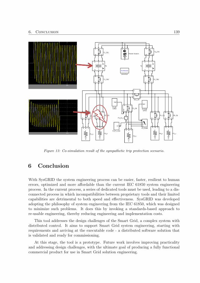
6. Conclusion 139
Figure 13: Co-simulation result of the sympathetic trip protection scenario.
6 Conclusion
With SysGRID the system engineering process can be easier, faster, resilient to humanerrors, optimized and more affordable than the current IEC 61850 system engineeringprocess. In the current process, a series of dedicated tools must be used, leading to a dis-connected process in which incompatibilities between proprietary tools and their limitedcapabilities are detrimental to both speed and effectiveness. SysGRID was developedadopting the philosophy of system engineering from the IEC 61850, which was designedto minimize such problems. It does this by invoking a standards-based approach tore-usable engineering, thereby reducing engineering and implementation costs.
This tool addresses the design challenges of the Smart Grid, a complex system withdistributed control. It aims to support Smart Grid system engineering, starting withrequirements and arriving at the executable code - a distributed software solution thatis validated and ready for commissioning.
At this stage, the tool is a prototype. Future work involves improving practicalityand addressing design challenges, with the ultimate goal of producing a fully functionalcommercial product for use in Smart Grid solution engineering.

140 Paper A
References
[1] X. Fang, S. Misra, G. Xue, and D. Yang, “Smart grid - 2014; the new and improvedpower grid: A survey,” IEEE Communications Surveys Tutorials, vol. 14, no. 4, pp.944–980, Fourth 2012.
[2] “IEC 61499-1: Function blocks-part 1 architecture,” International Standard, FirstEdition, Geneva, vol. 1, 2012.
[3] “IEC 61850-6: Configuration description language for communication in electricalsubstations related to ieds,” International Standard, First Edition, Geneva, vol. 2,2012.
[4] V. Vyatkin and I. S. of America, IEC 61499 function blocks for embedded and dis-tributed control systems design. ISA-Instrumentation, Systems, and AutomationSociety, 2007.
[5] N. Higgins, V. Vyatkin, N. K. C. Nair, and K. Schwarz, “Distributed power systemautomation with iec 61850, iec 61499, and intelligent control,” IEEE Transactionson Systems, Man, and Cybernetics, Part C (Applications and Reviews), vol. 41,no. 1, pp. 81–92, Jan 2011.
[6] G. Zhabelova and V. Vyatkin, “Multiagent smart grid automation architecture basedon iec 61850/61499 intelligent logical nodes,” IEEE Transactions on Industrial Elec-tronics, vol. 59, no. 5, pp. 2351–2362, May 2012.
[7] NIST, “Nist framework and roadmap for smart grid interoperability standards, re-lease 3.0,” 2014. [Online]. Available: http://www.nist.gov/smartgrid/upload/NIST-SP-1108r3.pdf
[8] R. Santodomingo, J. Rodrıguez-Mondejar, and M. Sanz-Bobi, “Ontology matchingapproach to the harmonization of cim and iec 61850 standards,” in Smart GridCommunications (SmartGridComm), 2010 First IEEE International Conference on.IEEE, 2010, pp. 55–60.
[9] F. Andren, M. Stifter, and T. Strasser, “Towards a semantic driven frameworkfor smart grid applications: Model-driven development using cim, iec 61850 andiec 61499,” Informatik-Spektrum, vol. 36, no. 1, pp. 58–68, Feb 2013. [Online].Available: http://dx.doi.org/10.1007/s00287-012-0663-y
[10] T. Strasser, M. Stifter, F. Andren, D. B. de Castro, and W. Hribernik, “Applyingopen standards and open source software for smart grid applications: Simulation ofdistributed intelligent control of power systems,” in 2011 IEEE Power and EnergySociety General Meeting, July 2011, pp. 1–8.
[11] C.-W. Yang, G. Zhabelova, V. Vyatkin, N. K. C. Nair, and A. Apostolov, “Smartgrid automation: Distributed protection application with iec61850/iec61499,” in

141
IEEE 10th International Conference on Industrial Informatics, July 2012, pp. 1067–1072.
[12] G. Zhabelova, V. Vyatkin, and N. K. C. Nair, “Standard-based engineering anddistributed execution framework for intelligent fault management for freedm sys-tem,” in IECON 2011 - 37th Annual Conference of the IEEE Industrial ElectronicsSociety, Nov 2011, pp. 2724–2729.
[13] G. Arthurs, “Model-based system engineering elements for deploying an efficientdevelopment environment,” Publication of Telelogic, an IBM Company, 2008.
[14] K. Brand, C. Brunner, and W. Wimmer, “Design of iec 61850 based substationautomation systems according to customer requirements,” Indian Journal of Powerand River Valley Development, vol. 61, no. 5, p. 87, 2011.
[15] T. Strasser, F. Andren, V. Vyatkin, G. Zhabelova, and C.-W. Yang, “Towards aniec 61499 compliance profile for smart grids review and analysis of possibilities,” inIECon 2012-38th Annual Conference on IEEE Industrial Electronics Society. IEEE,2012, pp. 3750–3757.
[16] C. h. Yang, G. Zhabelova, C.-W. Yang, and V. Vyatkin, “Cosimulation environmentfor event-driven distributed controls of smart grid,” IEEE Transactions on IndustrialInformatics, vol. 9, no. 3, pp. 1423–1435, Aug 2013.
[17] A. Apostolov and B. Vandiver, “Iec 61850 goose applications to distribution pro-tection schemes,” in 2011 64th Annual Conference for Protective Relay Engineers,April 2011, pp. 178–184.

142

Paper B
On Automatic Generation ofIEC61850/IEC61499 SubstationAutomation Systems Enabled by
Ontology
Authors:Chen-Wei Yang, Valeriy Vyatkin, Arash Mousavi and Victor Dubinin
Reformatted version of paper originally published in:2015 IEEE Annual Conference of the IEEE Industrial Electronics Society (IECON)
c© 2017, IEEE, Reprinted with permission.
143

144
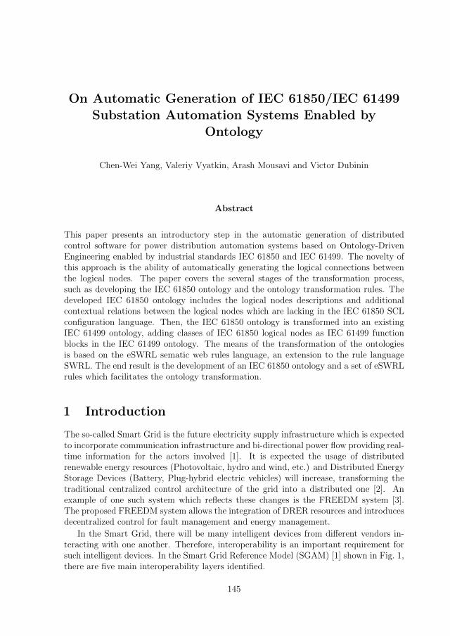
On Automatic Generation of IEC 61850/IEC 61499
Substation Automation Systems Enabled by
Ontology
Chen-Wei Yang, Valeriy Vyatkin, Arash Mousavi and Victor Dubinin
Abstract
This paper presents an introductory step in the automatic generation of distributedcontrol software for power distribution automation systems based on Ontology-DrivenEngineering enabled by industrial standards IEC 61850 and IEC 61499. The novelty ofthis approach is the ability of automatically generating the logical connections betweenthe logical nodes. The paper covers the several stages of the transformation process,such as developing the IEC 61850 ontology and the ontology transformation rules. Thedeveloped IEC 61850 ontology includes the logical nodes descriptions and additionalcontextual relations between the logical nodes which are lacking in the IEC 61850 SCLconfiguration language. Then, the IEC 61850 ontology is transformed into an existingIEC 61499 ontology, adding classes of IEC 61850 logical nodes as IEC 61499 functionblocks in the IEC 61499 ontology. The means of the transformation of the ontologiesis based on the eSWRL sematic web rules language, an extension to the rule languageSWRL. The end result is the development of an IEC 61850 ontology and a set of eSWRLrules which facilitates the ontology transformation.
1 Introduction
The so-called Smart Grid is the future electricity supply infrastructure which is expectedto incorporate communication infrastructure and bi-directional power flow providing real-time information for the actors involved [1]. It is expected the usage of distributedrenewable energy resources (Photovoltaic, hydro and wind, etc.) and Distributed EnergyStorage Devices (Battery, Plug-hybrid electric vehicles) will increase, transforming thetraditional centralized control architecture of the grid into a distributed one [2]. Anexample of one such system which reflects these changes is the FREEDM system [3].The proposed FREEDM system allows the integration of DRER resources and introducesdecentralized control for fault management and energy management.
In the Smart Grid, there will be many intelligent devices from different vendors in-teracting with one another. Therefore, interoperability is an important requirement forsuch intelligent devices. In the Smart Grid Reference Model (SGAM) [1] shown in Fig. 1,there are five main interoperability layers identified.
145

146 Paper B
Figure 1: Reference Smart Grid model from NIST [1]
The main focus of this work is on the lower rung of the interoperability layers cen-tred on harmonizing the communication and the component layers. The two standardswhich are suitable for the harmonization of these two interoperability layers are the sub-station automation standard IEC 61850 and the distributed automation standard IEC61499. IEC 61850 was first introduced as a standard for substation automation systems.The aim of the standard is to standardize the communication in substation automa-tion systems (SAS) and enabling interoperability between Intelligent Electronic Devices(IED) from different device vendors. Its advantage in providing a standardized meansof communication between distributed IED devices will be greatly beneficial to futuresmart grid systems. While IEC 61850 provides a comprehensive information model ofsubstation automation components, the internal implementation of control elements orthe control logic of IEC 61850 logical nodes is out of the scope of the standard. However,another open standard, IEC 61499, has been proposed in [4] to complement IEC 61850by implementing the internal control of the IEC 61850 logical nodes. IEC 61499 definesa reference architecture for distributed automation control systems, which comprises ofsuch design artefacts as basic and composite function blocks (FB). FBs are capable ofcapturing the IEC 61850 hierarchical information model from the logical node level tothe basic data level. In addition, it provides a native platform for designing distributedcontrol logic for IEC 61850 systems. There has been a number of works following [4, 5, 6]illustrating the benefits of the standards harmonization in various application scenarios.This work is a next step in the harmonization effort, aiming at automatic generationof IEC 61850 and IEC 61499 based control systems using Ontology Driven Engineering(ODE).
The paper is structured in the following manner. Chapter II will discuss the relatedworks in IEC 61850 and IEC 61499. In addition, existing works in automatic codegeneration of IEC 61850 systems are also discussed. Chapter III presents the novel idea

2. Related Works 147
of automatically generating IEC 61850/61499 systems using ODE. Chapter IV providesa case study, which illustrates the initial transformation process of the proposed solutionand the conclusion of the paper is in Chapter V.
2 Related Works
2.1 IEC 61850 and IEC 61499
The idea of combining IEC 61850 and IEC 61499 into a distributed substation automationsolution and prototypes of such solution is discussed in [4, 5, 6] with a reference exam-ple using the function block development platform FBDK. In addition, a co-simulationenvironment was also proposed between IEC 61499 and Matlab Simulink to provide anenvironment for validating the IEC 61850/61499 control systems. The concept of Intelli-gent Logical Nodes (iLN) is the IEC 61499 realizations of the IEC 61850 logical nodes asfunction blocks. The benefits of the iLN concept are that in addition of fully capturingthe hierarchical logical node information models in IEC 61499 function blocks, the iLNconcept also provides a platform where intelligence or logic could be added into the log-ical nodes providing the ability of decision making for each logical nodes. Thus creatinga distributed system where each distributed node (Group of the intelligent logical nodes)is capable of collaborating and making decisions in a distributed manner for smart gridcontrol and protection schemes.
There are existing research works in the substation automation domain which alsohighlights the viability of such solution. Article [7] illustrates an IEC 61850 based pro-tection scheme with GOOSE messaging implemented with IEC 61499 and IEC 61850using the IEC 61499 development platform nxtStudio. In [8], GOOSE messaging func-tion blocks were developed in the function block development platform ISaGRAF toallow interoperable communication between IEC 61850/61499 solutions and commercialIEC 61850 Intelligent Electronic Devices (IED). Another solution presented in [9] usesopen-source function block development platform 4DIAC and the Matlab Power SystemAnalysis Toolbox (PSAT) to create a smart grid co-simulation environment. All theserelated works demonstrate the potential of the IEC 61850/61499 synergy.
2.2 Automatic Generation of IEC 61850/IEC 61499 Systems
There are existing research works which apply automatic generation to create IEC 61850based control systems [10, 11]. The source of generation is commonly the IEC 61850System Configuration Language (SCL). SCL is an XML based configuration languageintroduced to allow the exchange of system configuration between IEC 61850 systems.There are in total six types of SCL configuration files and each configuration file type isused to configure a different part of the IEC 61850 system. Examples of SCL files includethe Configured IED Description (CID) for configuring individual IED devices and theSystem Configuration Description (SCD). The SCD file captures the complete configu-ration of an IEC 61850 system, which includes logical node definitions, communication

148 Paper B
configurations and individual IED configurations. In most of the existing works where theautomatic generation of IEC 61850 system is concerned, the SCD file is used as the sourceof generation since it contains the entire configuration of an IEC 61850 system. The sec-tions of the SCD file, which are used for the generation, are the DataTypeTemplates,the IED section and the communication section. The DataTypeTemplates contains thedefinitions of the all logical nodes used in the IEC 61850 system. This is essential as thedefinitions constitute the multi-layer information model of the logical node including theDataObjects and the DataAttributes of each unique logical node model. The IED sectioncaptures the configurations of each IED devices in the IEC 61850 system. There can bemore than one IED device within a system and there will be an IED section for each IEDin the system. The communication section contains the configuration of the communica-tion protocols such as Generic Object-Oriented Substation Event (GOOSE) messagingand Server/Client communication configurations. The communication section configuresthe entire communication network of the IEC 61850 system defining the addressing ofeach IED devices (sub-networks and networks), the packaging of data for transmission(e.g. GOOSE Dataset) and the signal flow defining the data exchange between logicalnodes. As mentioned previously, there are existing works, which automatically generatecode for IEC 61850 systems. However, there is very little existing work on generatingIEC 61499 based control systems based on IEC 61850 models.
In [10], an open platform for rapid-prototyping protection and control schemes withIEC 61850 is proposed. One part of the open platform is to automatically generate thelow-level communication configurations and the logical node information model. Lower-level communication includes GOOSE messaging (Configuration of GOOSE datasets)and Sampled-Value (SV) messaging. In [10], the SCD file is used as the source of theautomatic generation process. The target code is generated in the C programming lan-guage. The information models are generated by parsing the SCD XML. The logicalnode definitions are extracted from SCD and each hierarchical level of the logical node isgenerated. The data type of each attribute, along with data object types and the logicalnode types are represented as hierarchical C data structure.
In [12], a toolchain for smart grid automation framework for the design of IEC61850/IEC 61499 is proposed with automatic generation as being the core of the frame-work. The toolchain, also known as SysGRID, takes the SCL XML as an input toautomatically generate the IEC 61850/IEC 61499 system. The automatic generationprocess is ruled based which parses the SCD XML to an equivalent IEC 61499 XML. Hi-erarchical logical nodes’ information models are generated as (composite) function blocktypes called Intelligent Logical Nodes (iLN) [6].
A shortcoming of the SysGRID toolchain is the lack of ability to create meaningfullogical connections between the logical node function block instances in the generatedIEC 61499 application. Logical connections between function blocks define the controland data flow between blocks and are essential for the complete definition of the functionblock application’s semantics. This work aims to take the automatic generation a stepfurther to allow the logical connections between the logical node function blocks to beautomatically connected.

3. Novel Approach 149
3 Novel Approach
3.1 Ontology as the basis of IEC 61499 code generation
There are existing works where ontology has been applied in the IEC 61850 researchdomain. The majority use of ontology currently is for the harmonizing IEC 61850 andthe Common Information Models (CIM) which includes IEC61970 and IEC61968 asshown in the work [13]. However, ontology has not yet been applied in the applicationof automatic generation of IEC 61850 substation automation systems. In the domainof IEC 61499, ontology is already used for the purpose of automatic generation of IEC61499 control systems. Article [14] utilizes ontology to facilitate the transformation ofIEC 61499 systems from traditional IEC61131-3 PLC systems. In [15], ODE was used asthe basis for the automatic generation of IEC 61499 control codes for a Baggage HandlingSystem.
3.2 Contextual relations beytween logical nodes
Even though IEC 61850 provides a comprehensive library of semantic models known aslogical nodes, there is a lack of concrete semantic information attached to the logicalnodes. This was intentional on the part of the TC57 working group to ensure interoper-ability between the logical nodes. Since IEC 61499 is a block diagram based language,logical connections between logical nodes showing the flow of data are important in thedesign of IEC 61499 control systems.
In the first edition of the IEC 61850 standard, the data variables defined in eachlogical node could be classified as settings, control and output. The classification ofvariables as input variable is intentionally avoided to preserve interoperability from thecommunication point of view. From the communication’s point of view, it is not neces-sary to standardize input variables. Interoperability can be achieved by standardizingvariables, such as settings, status and output variables. For example, between the logicalnodes TCTR (Current Transformer Logical Nodes) and PIOC (Instantaneous Overcur-rent Logical Node), there are no clearly defined relationships between the two logicalnodes. However, relations between the two logical nodes can be defined from a partic-ular context. In the context of overcurrent protection, TCTR will have a direct logicalconnection to the PIOC logical nodes as the PIOC logical node requires the measure-ment readings from the current transformer logical node TCTR to determine whetheran overcurrent fault has occurred. Therefore, simply having an ontological model of anIEC 61850 configuration derived from the SCL configuration is not enough, contextualinformation which provides logical relations between logical nodes in IEC 61850 basedprotection schemes is also necessary in order to infer the relations between the logicalnodes. The advantage of using ontology as the system container is that it is able to cap-ture semantic relationships between the IEC 61850 components (I.E. the logical nodes)whereas XML is only able to capture the syntactical relationships between the IEC 61850components. In addition, the semantic correctness of the transformed target IEC 61499ontology can be checked by using semantic rules defined in the form such as SQWRL.

150 Paper B
3.3 Automatic generation of IEC 61499 driven by ODE
The idea of using ODE for the purpose of automatically generating IEC 61499 systemswas first proposed in [15]. The Semantic Web Rule Language (SWRL) is a languageused to express rules and logic for the Semantic Web. Due to the rule of monotonicity,SWRL cannot be used to modify existing information in the ontology. This meansthat it is not possible to create new instances, delete existing instances or relationsbetween existing instances. This is problematic when generating IEC 61499 code as newinstances of function blocks, input and output interfaces need to be dynamically created.To overcome these limitations, an extension to the SWRL language called eSWRL wasproposed in [15] which supports the creation and deletion of classes, object propertiesand class instances. The justifications and advantages of using eSWRL for the purposeof ontology transformation can be found at [15].
The case study used in [15] was a baggage handling system. For this paper, a sim-ilar approach to code generation is applied, but the application domain is substationautomation control using IEC 61850 and IEC 61499. Due to size limitations, only thefirst stage of the automatic generation process is discussed in this paper, covering thedevelopment of the IEC 61850 ontology and the ontology transformation rules used totransform the IEC 61850 ontology to the IEC 61499 ontology using eSWRL. The IEC61499 ontology will be adopted from the existing work, which contains a generic (domainneutral) ontological description of an IEC 61499 system not including elements of IEC61850. The Prolog-based component of the transformation process, which implementsthe eSWRL rules, is not covered in this paper.
4 Case Study: Overcurrent Protection
4.1 Sympathetic tripping feeder model
The case study used to illustrate the initial transformation process is the SympatheticTripping case from [7]. For illustrative purposes, only one feeder branch will be consideredfor this paper. The protection scheme, however, will still be adopted from the oneshown in [7]. The simplified feeder plant model is shown in Fig. 2. The feeder plantconsists of a current transformer and a circuit breaker. The associating IEC 61850 logicalnodes for this feeder are the Current Transformer logical node TCTR, the InstantaneousOvercurrent protection logical node PIOC, the Tripping Condition logical node PTRCand the Circuit Breaker logical node XCBR.
The protection scheme is adopted from the one shown in [7] as illustrated in Fig. 3.The current Transformer TCTR will send periodic current readings to the Overcur-rent Protection logical node PIOC. The signal, which contains the current reading, isthe TCTR.AmpSv instMag f signal. The PIOC will compare the internal overcurrentthreshold reading against the received current reading from the TCTR logical node. Ifthe received current reading is above the pre-set threshold, then the PIOC logical nodewill generate a PIOC.Op general signal to the Trip Conditioning logical node PTRC.

4. Case Study: Overcurrent Protection 151
Figure 2: Simplified Feeder Plant Model (SympatheticTrip) and the associating Logical Nodes.
Figure 3: IEC 61850 Overcurrent Protection Signal Passing (Sympathetic Trip).
The PTRC logical node will check its internal condition of tripping. In this scenario,an overcurrent occurrence is enough for the tripping condition to be satisfied. Once thetrip condition is satisfied, the PTRC logical node will generate a PTRC.Tr general tripsignal to the Circuit Breaker logical node XCBR. The circuit breaker will open or closedepending on the value of the PTRC.Tr general signal. The PTRC.Tr general signalis of type Boolean and actuates the circuit breaker to open when the PTRC.Tr generalvalue is true and to close when the PTRC.Tr general value is false.
4.2 Ontology of IEC 61850 logical nodes
The IEC 61850 ontology of the case study plant model is implemented in the ontologyeditor Protege [16]. The simplified ontology model of the IEC 61850 logical node is shownin Fig. 4.
The hierarchical model of the IEC 61850 logical node is made up of three levels. Thetop level is the logical node. Each logical node is made up of n- instances of data objects,which makes up the middle layer. Each data object is made up of n- data attributes,

152 Paper B
Figure 4: Ontology of IEC 61850 logical nodes in Protege showing Classes (Left), Object Prop-erties (Mid) and Data Properties (Right).
which makes up the lower layer. As can be seen in Fig. 4, there are nine classes. TheTCTR, PIOC, PTRC and the XCBR classes are the logical node classes. The ACT, ASG,DPL, SAV and the SPS class are the data object classes. The data attributes of the dataobjects are implemented as data properties. The individuals (in ontology, instances areknown as individuals) of the logical nodes are linked to the data objects via object prop-erties with the has- prefix. For example, the TCTR logical node contains a data objectcalled AmpSv of data object type SAV. The TCTR individual and the SAV individualare linked via the hasTCTR AmpSv object property. The two important properties ofnote are the hasConnection object property and the has connection var data property.The hasConnection object property between two logical node individuals indicates thata logical connection exists between the two logical nodes. The has connection var dataproperty of n logical node individual indicates the input variable that needs to be cre-ated in order to allow other logical nodes to make the logical connection. An exampleis the TCTR and the PIOC logical nodes as shown in Fig. 3, the TCTR logical nodeneeds to send the current reading AmpSv instMag f value to the PIOC logical node.The hasConnection object property will be created between the TCTR individual andthe PIOC individual indicating that TCTR has a logical connection from itself and thePIOC logical node. In addition, the has connection var will be added as a data propertyto the PIOC class individual with the AmpSv instMag f, indicating that an input variablecalled AmpSv instMag f need to be created on the input interface of the PIOC functionblock.
4.3 Logical node dependent input variables
In the original iLN proposal in [6], each iLN function block has mirroring input andoutput variables. That is all data variables defined in the IEC 61850 logical node typeare made as input and output variables of the iLN function block. For example, the PIOClogical node has the Op general variable to indicate that an overcurrent condition hasbeen detected.When implemented as an iLN, the input of the PIOC logical node functionblock will have an input named Op general in and a function block output variable namedOp general out as shown in Fig. 5. It makes sense to have the Op general out variableas it indicates that an overcurrent condition has been detected and the intended use is

4. Case Study: Overcurrent Protection 153
to have this information passed onto trip conditioning logical node PTRC. However, itmakes very little sense to have the Op general in as an input variable.
Figure 5: iLN function block of PIOC with mirroring input and output interface.
As discussed previously in chapter III, data variables within each logical node canbe classified as settings, controls and Outputs variables. Firstly, let’s categorize thesevariables as either input or output variables in terms of IEC 61499 function blocks.Outputs variables are usually logical node status variables, measured values or meteredvalues that need to be passed onto other connecting logical nodes. In the context of IEC61499 function blocks, these types of variables are likely to be output variables. Settingsare variables, which are necessary to parameterize the initial conditions of the logical nodeand are not likely to change its value after the initialization stage. When implementedas a function block, settings variables are likely to be input variables. Control variablesare binary or setpoint values, which are usually external control signals that are modifiedremotely or manual control via HMI panels. In terms of IEC 61499 function block,control variables would also be input variables to the function block. Although bothsettings and control variables are input variables when implemented as function blocks,what these two types of input variables have in common is that these types of variabledo not require information from its connecting logical node. Therefore, it is possible tosimply parameterize these types of variables and contextual relationships play almost nopart in these variables.
What is of interest are the input variable which requires logical connections fromother logical nodes as these variables usually do not exist in the connecting logical nodeto allow the logical connection to take place. That is the input variables are dependenton the logical nodes, which are connected to. This can be illustrated by the two iLNfunction blocks in Fig. 6.
The iTCTR function block contains two data variables. The EEName name variableis a description variable, which describes the name of the TCTR logical node and it is aninput variable to the function block. The AmpSv instMag f is a measured variable whichmeasures the periodic current readings and it is an output variable of the function blocks.The iPIOC logical node contains three variables, but only two of the variables are definedin the PIOC class. The setting variable StrVal setMag f sets the Overcurrent Thresholdvalue and it is an input variable to the function block. The Op general variable is a
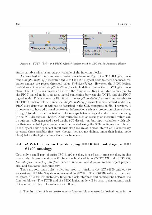
154 Paper B
Figure 6: TCTR (Left) and PIOC (Right) implemented in IEC 61499 Function Blocks.
status variable which is an output variable of the function blocks.As described in the overcurrent protection scheme in Fig. 3, the TCTR logical node
sends AmpSv instMag f measured value to the PIOC logical node to check the measuredvalues against the preset threshold value StrVal setMeg f. However, the PIOC logicalnode does not have an AmpSv instMag f variable defined under the PIOC logical nodeclass. Therefore, it is necessary to create the AmpSv instMag f variable as an input tothe PIOC logical node to allow a logical connection between the TCTR and the PIOClogical node. This is shown in Fig. 6 with the AmpSv instMag f as an input variable tothe PIOC function block. Since the AmpSv instMag f variable is not defined under thePIOC class definition, it will not be described in the SCL configuration file. Therefore, itis necessary to have additional contextual information such as a protection scheme shownin Fig. 3 to add further contextual relationships between logical nodes that are missingin the SCL description. Logical Node variables such as settings or measured values canbe automatically generated based on the SCL description, but input variables, which relyon their connected logical node cannot be created using the SCL configuration. Thus itis the logical node dependent input variables that are of utmost interest as it is necessaryto create these variables first (even though they are not defined under their logical nodeclass) before the logical connections can be made.
4.4 eSWRL rules for transforming IEC 61850 ontology to IEC61499 ontology
Note only a small part of entire IEC 61499 ontology is used as a target ontology in thiscase study. It are domain-specific function blocks of type iTCTR FB and iPIOC FB,has interface, is part of interface, event connection, and data connection object proper-ties, and has name data property.
There are four main rules, which are used to transform the IEC 61850 ontology toan existing IEC 61499 system represented in eSWRL. The eSWRL rules will be usedto create FB class, FB instances, function block interfaces and connections between thefunction blocks. The TCTR and the PIOC logical node will be used to demonstrate eachof the eSWRL rules. The rules are as follows:
1. The first rule set is to create generic function block classes for logical nodes in the

4. Case Study: Overcurrent Protection 155
target IEC 61499 ontology. That is, for each logical node class in the IEC 61850ontology, the corresponding class will be created in the IEC 61499 ontology. Tocreate a new class, the createClass [15] operator can be invoked. The syntax forthe createClass operator is:
eswrl : createClass({? < variable name > | < class name >})
To create TCTR FB class (called iTCTR FB), the following rule can be used.
e swr l : t h e r e I s C l a s s (TCTR)−>e swr l : c r e a t e C l a s s (iTCTR FB)
2. The second rule is to create an instance of the newly created iTCTR FB class ifa corresponding individual exists in the IEC 61850 ontology. To create a new in-stance, the createInstance operator will be used. The syntax for the createInstanceoperator is:
eswrl : createInstance({? < variable name > | < class name >} ,
{? < variable name > | < class instance name >})
To create the new instance, the following rules can be used.
TCTR(? t c t r l n ) ,has name (? t c t r l n , ?nm)−>e swr l : c r e a t e I n s t a n c e (iTCTR FB , ? t c t r f b ) ,has name (? t c t r f b , ?nm) .
It should be noted that a link between an instance of logical node (LN) class andthe corresponding instance of FB class is established on the basis of equality oftheir names.
3. The third rule set is to create interfaces of logical node function blocks. To illustratethis set of rules, PIOC logical node will be used since PIOC has an input variablefrom TCTR logical node. In addition, this type of input variables will also have acomplementary event input created. E.g. for PIOC logical node, AmpSv instMag finput variable will have a complementary event input called fromTCTR created.To create the function block interfaces, the same createInstance operator is used.

156 Paper B
The rules for creating the interface of PIOC function block are as follows:The first step is to create the INIT (Initialization) and INITO (Finish Initializa-tion) event input and output.
iPIOC FB (? p i o c f b )−>e swr l : c r e a t e I n s t a n c e ( FBinter face , ? p i o c f b i n t e r f a c e ) ,h a s i n t e r f a c e (? p i oc fb , ? p i o c f b i n t e r f a c e ) ,e swr l : c r e a t e I n s t a n c e ( FBevent , ? e1 ) ,has name (? e1 , ”INIT ”) ,e swr l : c r e a t e I n s t a n c e ( FBevent , ? e2 ) ,has name (? e2 , ”INITO”) ,i s p a r t o f i n t e r f a c e (? e1 , ? p i o c i i n t e r f a c e ) ,i s p a r t o f i n t e r f a c e (? e2 , ? p i o c i i n t e r f a c e ) .
The second step is to add PIOC specific variables StrVal SetMag f (Setting) andOp general (Status).
iPIOC FB (? p i o c f b ) ,h a s i n t e r f a c e (? p i oc fb , ? p i o c f b i n t e r f a c e )−>e swr l : c r e a t e I n s t a n c e ( FBvariable , ?d1 ) ,has name (? d1 , ” StrVal setMag\ f ” ) ,i s p a r t o f i n t e r f a c e (? d1 , ? p i o c f b i n t e r f a c e ) ,e swr l : c r e a t e I n s t a n c e ( FBvariable , ?d2 ) ,has name (? d2 , ” Op general ” ) ,i s p a r t o f i n t e r f a c e (? d2 , ? p i o c f b i n t e r f a c e ) .
The third step is to add the AmpSv instMag f as an input variable from TCTRlogical node. This variable is determined in the rule implicitly by means of theinstance of PIOC LN class. In addition, it is also necessary to create a complemen-tary fromTCTR input event for AmpSv instMag f input variable.
PIOC(? p i o c l n ) , iPIOC FB (? p i o c f b ) ,has name (? p i o c ln , ?nm) ,has name (? p ioc fb , ?nm) ,ha s connec t i on var (? p i o c ln , ?connVar ) ,h a s i n t e r f a c e (? p i oc fb , ? p i o c f b i n t e r f a c e )−>e swr l : c r e a t e I n s t a n c e ( FBvariable , ?v ) ,has name (?v , ?connVar ) ,e swr l : c r e a t e I n s t a n c e ( FBevent , ? e ) ,

4. Case Study: Overcurrent Protection 157
has name (? e , ”fromTCTR”) ,i s p a r t o f i n t e r f a c e (? e , ? p i o c f b i n t e r f a c e ) ,i s p a r t o f i n t e r f a c e (?v , ? p i o c f b i n t e r f a c e ) .
4. The fourth rule is to make the connection between AmpSv instMag f output vari-able of TCTR function block and AmpSv instMag f input variable of PIOC functionblock. Firstly, it is necessary to make the event connection between INITO eventoutput of TCTR function block to INIT event input of PIOC function block.
TCTR(? t c t r l n ) ,PIOC(? p i o c l n ) ,hasConnection (? t c t r l n , ? p i o c l n ) ,iTCTR FB(? t c t r f b ) ,has name (? t c t r l n , ?nm1) ,has name (? t c t r f b , ?nm1) ,iPIOC FB (? p i o c f b ) ,has name (? p i o c ln , ?nm2) ,has name (? p ioc fb , ?nm2) ,h a s i n t e r f a c e (? t c t r f b , ? t c t r f b i n t e r f a c e ) ,h a s i n t e r f a c e (? p i oc fb , ? p i o c f b i n t e r f a c e ) ,i s p a r t o f i n t e r f a c e (? e1 , ? t c t r f b i n t e r f a c e ) ,has name (? e1 , ’ ’ INITO ’ ’ ) ,i s p a r t o f i n t e r f a c e (? e2 , ? p i o c f b i n t e r f a c e ) ,has name (? e2 , ”INIT ”)−>event connec t i on (? e1 , ? e2 ) .
Secondly, AmpSv instMag f variable from TCTR logical node will be connected toAmpSv instMag f variable on the PIOC logical node.
TCTR(? t c t r l n ) ,PIOC(? p i o c l n ) ,hasConnection (? t c t r l n , ? p i o c l n ) ,iTCTR FB(? t c t r f b ) ,has name (? t c t r l n , ?nm1) ,has name (? t c t r f b , ?nm1) ,iPIOC FB (? p i o c f b ) ,has name (? p i o c ln , ?nm2) ,has name (? p ioc fb , ?nm2) ,h a s i n t e r f a c e (? t c t r f b , ? t c t r f b i n t e r f a c e ) ,h a s i n t e r f a c e (? p i oc fb , ? p i o c f b i n t e r f a c e ) ,i s p a r t o f i n t e r f a c e (? e1 , ? t c t r f b i n t e r f a c e ) ,

158 Paper B
has name (? e1 , ”toPIOC ”) ,i s p a r t o f i n t e r f a c e (? e2 , ? p i o c f b i n t e r f a c e ) ,has name (? e2 , ”fromTCTR”) ,i s p a r t o f i n t e r f a c e (? d1 , ? t c t r f b i n t e r f a c e ) ,has name (? d1 , ”AmpSv instMag f ”) ,i s p a r t o f i n t e r f a c e (? d2 , ? p i o c f b i n t e r f a c e ) ,has name (? d2 , ”AmpSv instMag f ”)−>event connec t i on (? e1 , ? e2 ) ,data connect ion (? d1 , ?d2 ) .
5 Conclusion
This is an initial work in proposing an ODE framework in the automatic generation of IEC61850/61499 systems. Ontology is adopted for the purpose of transformation as existingSCL configuration does not contain concrete contextual information between the logicalnodes. Expressing IEC 61850 systems in ontology allows the integration of protection-related information from protection schemes. The addition of a protection scheme whichspecifies contextual relations between the logical nodes enables logical connections to beautomatically created between the logical nodes when implemented as function blocks,which are lacking in existing IEC 61850/61499 based code generators. The initial stageof the transformation process involves transformation IEC 61850 ontology to an existingIEC 61499 ontology, creating an IEC 61499 ontology which describes the generic struc-ture of an IEC 61499 system and function blocks with IEC 61850 logical node interfacesand information of logical connections. The ontology transformation uses eSWRL, anextension to the semantic web rule language SWRL, which enables the creation of ontol-ogy classes, instances and properties. The IEC 61499 ontology is then subject to furthertransformation via Prolog to the final IEC 61499 control system.
References
[1] CENELEC, “Smart grid coordination group (sgcg) reference architecture smartgrid.”
[2] A. Ipakchi and F. Albuyeh, “Grid of the future,” IEEE Power and Energy Magazine,vol. 7, no. 2, pp. 52–62, March 2009.
[3] A. Huang, “Freedm system - a vision for the future grid,” in IEEE PES GeneralMeeting, July 2010, pp. 1–4.
[4] V. Vyatkin, G. Zhabelova, N. Higgins, M. Ulieru, K. Schwarz, and N. K. C. Nair,“Standards-enabled smart grid for the future energy web,” in 2010 Innovative SmartGrid Technologies (ISGT), Jan 2010, pp. 1–9.

References 159
[5] N. Higgins, V. Vyatkin, N. K. C. Nair, and K. Schwarz, “Distributed power systemautomation with iec 61850, iec 61499, and intelligent control,” IEEE Transactionson Systems, Man, and Cybernetics, Part C (Applications and Reviews), vol. 41,no. 1, pp. 81–92, Jan 2011.
[6] G. Zhabelova and V. Vyatkin, “Multiagent smart grid automation architecture basedon iec 61850/61499 intelligent logical nodes,” IEEE Transactions on Industrial Elec-tronics, vol. 59, no. 5, pp. 2351–2362, May 2012.
[7] C.-W. Yang, G. Zhabelova, V. Vyatkin, N. K. C. Nair, and A. Apostolov, “Smartgrid automation: Distributed protection application with iec61850/iec61499,” inIEEE 10th International Conference on Industrial Informatics, July 2012, pp. 1067–1072.
[8] J. Xu, C. W. Yang, G. Zhabelova, S. Berber, and V. Vyatkin, “Towards imple-mentation of iec 61850 goose messaging in iec 61499 environment,” in 2013 11thIEEE International Conference on Industrial Informatics (INDIN), July 2013, pp.464–470.
[9] T. Strasser, M. Stifter, F. Andren, D. B. de Castro, and W. Hribernik, “Applyingopen standards and open source software for smart grid applications: Simulation ofdistributed intelligent control of power systems,” in 2011 IEEE Power and EnergySociety General Meeting, July 2011, pp. 1–8.
[10] S. Blair, F. Coffele, C. Booth, and G. Burt, “An open platform for rapid-prototypingprotection and control schemes with iec 61850,” in 2013 IEEE Power Energy SocietyGeneral Meeting, July 2013, pp. 1–1.
[11] F. Andren, T. Strasser, and W. Kastner, “Towards a common modeling approachfor smart grid automation,” in IECON 2013 - 39th Annual Conference of the IEEEIndustrial Electronics Society, Nov 2013, pp. 5340–5346.
[12] C.-W. Yang, G. Zhabelova, and V. Vyatkin, “Sysgrid: Iec 61850 and iec 61499standard based engineering tool for smart grid automation design,” EAI EndorsedTransactions on Energy Web, vol. 3, pp. 1–8, July 2014.
[13] R. Santodomingo, J. A. Rodriguez-Mondejar, and M. A. Sanz-Bobi, “Ontologymatching approach to the harmonization of cim and iec 61850 standards,” in 2010First IEEE International Conference on Smart Grid Communications, Oct 2010,pp. 55–60.
[14] W. Dai, V. N. Dubinin, and V. Vyatkin, “Migration from plc to iec 61499 usingsemantic web technologies,” IEEE Transactions on Systems, Man, and Cybernetics:Systems, vol. 44, no. 3, pp. 277–291, March 2014.
[15] V. Dubinin, V. Vyatkin, C.-W. Yang, and C. Pang, “Automatic generation of au-tomation applications based on ontology transformations,” in Proceedings of the

160
2014 IEEE Emerging Technology and Factory Automation (ETFA), Sept 2014, pp.1–4.
[16] “Protege,” 2016. [Online]. Available: http://protege.stanford.edu
Paper C
Modelling of IEC 61850 MessagePassing for Automatic Generation
of Distributed Control
Authors:Chen-Wei Yang and Valeriy Vyatkin
Reformatted version of paper originally published in:2015 Annual Conference of the IEEE Industrial Electronics Society (IECON)
c© 2017, IEEE, Reprinted with permission.
161

162

Modelling of IEC 61850 Message Passing for
Automatic Generation of Distributed Control
Chen-Wei Yang and Valeriy Vyatkin
Abstract
The future distribution grid known as the smart grid will become more distributedin both infrastructure and control. IEC 61850 and IEC 61499 are two industrial stan-dards addressing the challenges presented by a decentralized infrastructure. This papercontributes to system engineering of smart grid automation by enabling automatic gen-eration of IEC 61499 control systems from IEC 61850 specifications. The areas whichthis paper fills is proposing a method to formally capture the logical node to logical nodemessage passing which is lacking in the IEC 61850 standard. The proposed method isto represent an IEC 61850 protection scheme as a graph and then integrated into theIEC 61850 ontology developed previously. The case study used is a sympathetic trippingprotection scenario which demonstrates how the process of developing the graph modelfrom the protection scheme and applying ontology rules to automatically generate theresultant IEC 61499 function blocks with meaningful connections between the logicalnodes.
1 Introduction
The future infrastructure of the electric distribution grid is set to evolve from a cen-tralized architecture to a more distributed architecture to allow the integration of greenenergy resources. Known as the ”Smart Grid”, the future distribution grid is said to besmart with the integration of bi-direction communication enabling real-time informationwithin the electric grid which allows both the utilities and the consumers to be activeparticipants in the generation and distribution of electricity. This new infrastructure hasbeen compared to the infrastructure of the internet, also called the ”Energy Internet”[1].
The key component in a future smart grid is a dependable and modern communi-cation infrastructure which enables intelligent smart grid functions and services such asadaptive protection and distributed power system management, etc. [2]. One interna-tional industrial standard, which is used widely in Europe, is the IEC 61850 standardfor the substation automation systems (SAS). The standard was originally developedfor the substation automation systems only introducing device interoperability to SASsystems. The standard has since been extended to include DER devices with the samecommunication protocols.
163

164 Paper C
IEC 61850 also introduced model-driven design paradigms in the form of SubstationConfiguration Language (SCL) to provide a standardized method for designing substationautomation systems. IEC 61850 proposed the idea of virtual intelligent electronic devices(IED) devices with information models known as Logical Nodes which formally describingthe functional requirements and physical requirements of a SAS system. For the purposesof interoperability, the TC57 working group behind the IEC 61850 standard intentionallyleft out the means to formally describe the logical implementation of the logical node’sfunctional requirements.
IEC 61499 is an industrial standard and a reference architecture for the design ofdistributed automation systems [3]. IEC 61499 provides design artefacts known as func-tion blocks which provides encapsulation, decomposition and other design features whichmakes designing de-centralized automation control systems less difficult compared totraditional 61131-3 automation control systems. IEC 61499 is used in several domainsincluding factory automation, material handling and recently, in the substation automa-tion domain [4]. Much like the top down model driven principles of IEC 61850 substationdesign where the substation is designed as a whole from with the system requirementsdefined as logical nodes to the eventual decomposition of the overall system to the config-uration of the individual IED devices. IEC 61499 shares the same design principles wherethe entire distributed control system is designed as a single system before distributingthe control system to individual Programmable Logic Controllers (PLC) controllers. Dueto this synergy and the similar model-driven design principles in both standards, IEC61499 is thought to be capable of filling the logical implementation of logical nodes whichis missing in the IEC 61850 standard.
This paper builds on the work in [5] where an architecture based on ontology isproposed which is capable of automatically generating IEC 61499 PLC control code basedon the formal specifications of IEC 61850. The work in [5] introduced the Semantic WebRule Language (SWRL) extension language eSWRL which includes features such as thedynamic creation of ontology class individuals which is lacking in the existing SWRLlanguage. This paper will focus on one aspect of the proposed architecture, which is amethod to formally model the message passing between logical nodes so it can be usedas part of the eSWRL framework.
The paper is structured as follows. Section II outlines the related works. Section IIIoutlines the case study system. Section IV discusses the methods of implementation andthe conclusion and future work are discussed in Section V.
2 Related Works
There are several ongoing research works involving both IEC 61850 and IEC 61499 withproposed architectures and co-simulation environments. [6, 7] proposes the intelligentlogical node architecture which represents each IEC 61850 logical nodes as an IEC 61499function block and implementing local agent intelligence within each iLN. Furthermore,co-simulation environments were also developed in [8] involving commercial IEC 61499development platform NxtStudio [9] and MATLAB Simulink. Alternatively, an open
3. Case Study: Sympathetic Trip 165
source co-simulation solution was also developed in [10], which uses 4DIAC [11] as theIEC 61499 development platform.
Model-driven engineering (MDE) is widely used in software engineering as it hasproven to be effective when designing big scale software applications. MDE follows themantra of ”everything is a model” [12] where the design paradigms are centred aroundmodels, be it platform dependent models (PDM) or platform independent models (PIM).Recently, [13] MDE has found its way into the automation industry. IEC 61850 can beconsidered as an MDE solution for the SAS systems with the introduction of the sub-station configuration language (SCL). The SCL configuration language is representedas XML document and there are a total of 6 types of SCL documents, each documentdescribing a different stage of the MDE design process. For example, the System Spec-ification Description (SSD) is used at the initial stage of design to define the formalspecifications of the system which includes functional and physical requirements repre-sented as logical nodes. The overall design of the whole system is called the SubstationConfiguration Description (SCD) which contains overall system configuration includingthe communication configuration, logical node definitions and individual IED configu-rations. The Configured IED Description (CID) is the configuration document for theIEDs in the system and there is one CID document for every IED device.
There are existing research works which also use the SCL configuration languageas the basis for the automatic generation of control systems, which is one componentof MDE engineering. An open-platform for rapid-prototyping protection and controlschemes based on IEC 61850 systems was proposed in [14]. The SCD document is used inthis work as the basis for transformation to automatically generate control base for the Cprogramming language. The SysGrid architecture in [15] is an MDE oriented architecturewhich utilizes the SCL configurations as the initial MDE models for modelling IEC61850/61499 systems. The SCL models, specifically the SCD description is used toautomatically generated IEC 61499 PLC control codes based on the iLN architecture.One limitation of the SysGrid architecture is the inability for the transformation engineto create meaningful connections between the resultant function blocks as the logicalnode to logical node semantic description is not captured in the SCL documents. Thework presented in this paper will attempt to address this limitation as part of the eSWRL[5] framework.
In [5], the eSWRL extension language is proposed to automatically generate IEC61850/61499 systems based on ontology descriptions. This paper carries on the workin [5] which outlines how protection schemas could be modelled as part of the eSWRLframework to create meaningful connections between the function blocks in the resultantIEC 61499 PLC code base.
3 Case Study: Sympathetic Trip
The case study system used in this paper is a simple distribution protection systemspresented in [16] demonstrating de-centralized protection as shown in Fig. 1. The de-centralized protection in the case study scenario includes sympathetic tripping and se-

166 Paper C
lective backup tripping implemented using IEC 61850. The protection shown in Fig. 1is sympathetic tripping. The de-centralized protection scheme is enabled by high-speedpeer-to-peer IEC 61850 Generic object oriented substation events (GOOSE) communi-cation which means the IEDs are constantly exchanging messages with each other toimplement the said protection function. In the context of IEC 61850, the messages andsignals which are exchanged between IED devices are captured in the SCL documents.What is not captured is the message passing between logical nodes since the aim of IEC61850 is to standardize communication between devices. In contrast, when the logicalnodes are implemented as function blocks in IEC 61499, message passing between logicalnodes becomes essential since each individual function blocks are required to communi-cate with each other to execute the implemented protection logic.
Figure 1: Simple distribution network for Sympathetic Tripping with distributed protection.
The protection scheme for a feeder IED is shown in Fig. 2. There are four logical nodesin this feeder protection which communicates with each other, 2 logical nodes receivingmessages from other IEDs and one LN sending messages to other IEDs. The 4 logicalnodes within the IED communicate in the following manner. The current transformerTCTR logical node receives the telemetry readings from the merging units and passesthe current reading value TCTR.AmpSv instMag f to the overcurrent PIOC logicalnode. The PIOC logical node compares the current reading with its internal overcurrent

4. Proposed Method 167
threshold. If the current is greater than the internal threshold value, the PIOC emitsthe PIOC.Op general message to the trip conditioning LN PTRC. The PTRC checksits own internal circuit breaker (CB) tripping conditions with the received overcurrentmessage and if a trip is necessary, it will emit a trip message PTRC.Tr general tothe circuit breaker LN XCBR. Externally, the PTRC also sends the tripping messageto the neighbouring feeders and the transformer IEDs as part of the sympathetic tripprotection to protect themselves from inrush currents. The PIOC LN receives PTRCmessages from other feeders to protect itself from inrush currents is a fault has occurredon its neighbouring feeders. Lastly, the XCBR LN is able to receive CB tripping signalsfrom the transformer IED as part of the selective-backup tripping protection where thefeeder IED is not able to clear its own fault if the IED becomes inoperable.
Figure 2: Overcurrent protection scheme of a feeder and its message. passing between logicalnodes andother IEDs.
An overview of the message passing between all the LNs within an IED and betweenIEDs is shown in Fig. 3. For reasons of clarity, only the inter-IED message passingof Feeder1, Feeder2 and the Transformer IED is highlighted. In the context of IEC61499, it is necessary for each of the logical nodes to be connected to each other andthese connections need to be captured formally before being converted to an ontologyrepresentation for automatic FB generation developed in [5].
4 Proposed Method
The method of modelling the connections between the logical nodes proposed in thiswork uses graph representation to reflect the information on message passing betweenlogical nodes. Graphs are widely used for modelling connected complex networks, asshown in [17, 18] where graphs are used to model complex Internet network. Besides, it is

168 Paper C
Figure 3: Message passing between LNs within IEDs and between IEDs in the sympathetictripping protection.
possible to map out the paths of communication in a graph model. In terms of protectionschemes, this is important since there are extremely stringent timing constraints whichmust be adhered to. Being able to map out the communication paths makes it possibleto compute the time it takes for an implemented protection function to respond and cleara fault when a fault is detected. In addition, it provides a method to address one of themain questions raised regarding IEC 61499 which is whether it is able to meet the timingrequirements of power system protection and control systems. Thirdly, the graph canbe used as an underlying model of IEC 61499 FB application, so the entire process ofautomatic program generation can be formally presented as a graph transformation.
The proposed method is as follows. Firstly, the protection scheme is Fig. 2 is rep-resented as a graph. The graph presents a machine-readable representation and acts asthe formal mathematical backend of the LN communication model. Then, the graph istransformed to its equivalent ontology in which eSWRL rules developed in [5] can thenbe used to automatically generate a complete IEC 61499 FB control program with mean-ingful connections between the FBs. The subsequent subsections will discuss the coresteps of the modelling process.
4.1 Modelling as a Graph
A graph representation of the message passing between the logical nodes shown in Fig. 2and Fig. 3 is presented in Fig. 4. Note that the graph in Fig. 4 shows the message passingbetween LNs within an IED device and between IED devices. In terms of IEC 61499design, it is not necessary to distinguish this difference at the early stage of design since

4. Proposed Method 169
the initial design stage is from the perspective of an application rather than on the devicelevel.
Figure 4: Graph showing the message passing between logical nodes.
Mathematically, the graph G is defined G = (V, E), where:
• V is the set of vertices (nodes)
• V = {TCTR F#, P IOC F#, PTRC F#, XCBR F#, TCTR T, PIOC T,PTRC T,XCBR T}
Where # represented the feeders numbered 1 to 5
• E is the set of edges (The links between the vertices)

170 Paper C
• E = {(TCTR F1, P IOC F1), (PIOC F1, PTRC F1), (PTRC F1, XCBR F1),(PTRC F1, P IOC F2), (PTRC F1, P IOC F3), (PTRC F1, P IOC F4),(PTRC F1, P IOC F5), (PTRC F1, P IOC T )...}
4.2 Transforming to Ontology
The next step is to convert this graph representation into the IEC 61850 ontology de-veloped in [5]. The transformation from graph to ontology can be considered as thefollowing:
• Each graph vertices is an ontology class LN
• Each graph edge is an ontology object property has LNConnections
• An ontology class LNConnections is introduced with the following data properties:
– LNC from is the source LN which sends the message
– LNC to is the destination LN which receives the message
– LNC name is the name of the message exchanged in the connection
– LNC type is the datatype of the message
An excerpt of the ontology representation of the graph in Fig. 4 is shown in Fig. 5.For reasons of clarity, only the data properties of LNC 1 are shown. According to Fig. 4,the PTRC T LN has 6 outgoing connections connection to XCBR T and XCBR F1 toXCBR F5. The connection between PTRC T and XCBR T is captured in the connectionLNC 1. The name of the message in LNC name is PTRC.Tr general and the datatypeof the message in LNC type is BOOLEAN. The LNC from data property signifies thesource of the message, which is PTRC T LN and the LNC to data property signifiesthe destination of the message, which is the XCBR T LN in Fig. 5. Note that boththe PTRC T LN and the XCBR T LN are linked to LNC 1 via the object propertyhas LNConnections since both LNs are involved in this message passing. In addition,the ontology class individuals LNC 2 to LNC 6 contains the message passing betweenPTRC T and XCBR F1 to XCBR F5. Note that the LNConnections class only containsa single message between a pair of LNs. E.g. in LNC 1, only the PTRC.Tr generalmessage is exchanged. If a pair of LN nodes exchanges more than a single message, thenan LNConnections individual for each message needs to be created.
4.3 Applying eSWRL to Generate FB Connections
The two vital data properties to take into account in the LNConnections class at this stageare LNC from and LNC to. These two data properties determine whether the messageis an input to the FB or an output of the FB. For example, consider the LNConnectionsclass individual LNC 1, the data properties are as follows:

4. Proposed Method 171
Figure 5: Ontology representation of the inter-LN connections.
• LNC from is PTRC T
• LNC to is XCBR T
• LNC name is PTRC T.Tr general
• LNC type is BOOLEAN
Consider the PTRC T logical node, the PTRC T.Tr general is an output data oftype BOOLEAN. For the XCBR T logical node, the PTRC T.Tr general is an inputdata of type Boolean. Therefore, the eSWRL query engine will first query the PTRC Tlogical nodes and see all the LNConnections individuals that it is associated with. Then,the query engine can look through LNC from and LNC to data properties to determinewhether the message is an input or an output to the LN FB. The eSWRL query is shownbelow. The relevant eSWRL operators are defined in [5]. Also, note that the ontologyused for IEC 61850 is based on the IEC 61850 UML model and the IEC 61499 ontologyused is based on the IEC 61499 Document Type Definition (DTD) file.
The rules used to create the output event and data FB interfaces are presented inListing. C.1. The clauses on the left side of − > are the antecedents or the conditionsand the consequent or the action is on the right. On the antecedent side, line 1 and 2are used to query for LNs in the ontology and store the name of the LN in the ?ln namevariable. Code 3,4 and 5 queries the LNConnection individuals and stores and the nameof the message and the name of the LN which sends the message (the LN in LNC from).Line 6 compares the name of the LN and the name of the LNC from LN to ensure thecorrect LN is selected.

172 Paper C
1 . LN(? ln ) ,2 . has name (? ln , ? ln name ) ,3 . LNConnections (? l n c o n n e c t i o n s ) ,4 . LNC from (? ln connec t i on s , ? lnc f rom ) ,5 . LNC name(? ln connec t i on s , ? lnc name ) ,6 . swrlb : s t r ingEqua l IgnoreCase (? ln name , ? lnc f rom )7 . −>8 . e swr l : c r e a t e I n s t a n c e ( Event , ? e1 ) ,9 . swrlb : s t r ingConcat (?e1Name , ? lnc name , ” Event ”) ,10 . has event name (? e1 , ?e1Name ) ,11 . e swr l : c r e a t e I n s t a n c e ( VarDeclarat ion , ?v1 ) ,12 . has VarDeclarationName (? v1 , ? lnc name ) ,13 . e swr l : c r e a t e I n s t a n c e ( EventOutputs , ? eo1 ) ,14 . has Event (? eo1 , ? e1 ) ,15 . e swr l : c r e a t e I n s t a n c e ( OutputVars , ?vo1 ) ,16 . has VarDec larat ion (? vo1 , ?v1 ) ,17 . e swr l : c r e a t e I n s t a n c e ( I n t e r f a c e L i s t , ? i l 1 ) ,18 . has EventOutputs (? i l 1 , ? eo1 ) ,19 . has OutputVars (? i l 1 , ?vo1 )
Listing C.1: Code snippets of eSWRL rules for creating event and variable interfaces.
Figure 6: Ontology hierarchy of FB interfaces and connections.
The events and data in the IEC 61499 ontology are connected with object propertiesin a hierarchical manner as shown in Fig. 6. Line 8 and 10 creates an event for the messageand line 11 and 12 create the message variable VarDeclaration. Line 13 and 14 creates theEventOutput individual which houses the Event created previously. The same applies toline 15 to 16 which creates the OutputVars individual housing the VarDeclaration. Line17 to 18 creates the IntefaceList individual which houses both the EventOutput and theOutputVars created previously. The last step is to create the FBType which will housethe InterfaceList. Note that the rule set for creating the input data interface would be

4. Proposed Method 173
the same as the one in Listing. C.1 except the LNC to data property is taken into accountin the antecedent and EventInputs and InputVars are created in the consequent.
Once the message interfaces described in the LNConnections individual are created,the next step is to make the connections between the said LNs in each LNConnectionsindividuals.Consider the code snippet in Listing. C.2, on the antecedent side, code line2 to 5 queries the LNConnections individuals and stores the data properties in vari-ables. The hierarchy of FB connections is shown in Fig. 6. The bottommost level is theConnection, which belongs to either the DataConnection class or the EventConectionsclasses depending on whether the connection, is an event or data connection. Both Dat-aConnections and EventConnections are then contained in the FBNetworks class sinceconnections only exist in an FB network. On the consequent side, line 11 to 15 createsthe Connection, the EventConnections and the object properties connecting the two classindividuals before adding the EventConnection individual to the FBNetwork in line 16.Line 17 to 22 performs the same action but with data connections.
1 . FBNetwork (? fbNetwork ) ,2 . LNConnections (? l n c o n n e c t i o n s ) ,3 . LNC from (? ln connec t i on s , ? lnc f rom ) ,4 . LNC to (? ln connec t i on s , ? l n c t o ) ,5 . LNC name(? ln connec t i on s , ? lnc name ) ,6 . −>7 . swrlb : s t r ingConcat (? srcEventName , ? lnc from , ” . ” ,
? lnc name , ” Event ”) ,8 . swrlb : s t r ingConcat (? dstEventName , ? lnc to , ” . ” ,
? lnc name , ” Event ”) ,9 . swrlb : s t r ingConcat (? srcVarName , ? lnc from , ” . ” ,
? lnc name ) ,10 . swrlb : s t r ingConcat (? dstVarName , ? lnc to , ” . ” ,
? lnc name ) ,11 . e swr l : c r e a t e I n s t a n c e ( connect ion , ? eventConnection ) ,12 . has Connect ion Source (? eventConnection , ? srcEventName ) ,13 . has Connect ion Dest inat ion (? eventConnection ,
?dstEventName ) ,14 . e swr l : c r e a t e I n s t a n c e ( EventConnections , ? eventCon ) ,15 . Has Connection (? eventCon , ? EventConnection ) ,16 . Has EventConnections (? fbNetwork , ? eventCon ) ,17 . e swr l : c r e a t e I n s t a n c e ( connect ion , ? varConnection ) ,18 . has Connect ion Source (? varConnection , ?srcVarName ) ,19 . has Connect ion Dest inat ion (? varConnection , ?dstVarName ) ,20 . e swr l : c r e a t e I n s t a n c e ( DataConnections , ?dataCon ) ,21 . Has Connection (? dataCon , ? varConnection ) ,22 . Has DataConnections (? fbNetwork , ?dataCon )
Listing C.2: Code snippets of eSWRL rules for creating connections between IEC 61499 FBs.

174 Paper C
5 Conclusion
The goal of this paper is to provide a formal modelling of the message passing semanticsbetween the LNs, which can be represented in an ontology to be applied to the eSWRLautomatic code generation architecture. This fills the missing void in the IEC 61850ontology developed in [5] which do not have LN to LN message passing information. TheIEC 61850 developed in [5] is based on the IEC 61850 SCL description, which only has theinter-IED message passing. But in the context of IEC 61499, message passing betweenLNs within an IED or between IEDs is vital and this proposed work addresses thislimitation. The proposed method converts a protection scheme, which has the messagepassing information to a graph. The graph is then converted to an ontology and addedto the existing IEC 61850 ontology which makes it possible to apply eSWRL rules toautomatically generate connections between LN FBs.
References
[1] A. Q. Huang, M. L. Crow, G. T. Heydt, J. P. Zheng, and S. J. Dale, “The futurerenewable electric energy delivery and management (freedm) system: the energyinternet,” Proceedings of the IEEE, vol. 99, no. 1, pp. 133–148, 2011.
[2] T. Strasser, F. Andren, J. Kathan, C. Cecati, C. Buccella, P. Siano, P. Leitao,G. Zhabelova, V. Vyatkin, P. Vrba et al., “A review of architectures and conceptsfor intelligence in future electric energy systems,” IEEE Transactions on IndustrialElectronics, vol. 62, no. 4, pp. 2424–2438, 2015.
[3] “IEC 61499-1: Function blocks-part 1 architecture,” International Standard, FirstEdition, Geneva, vol. 1, 2012.
[4] V. Vyatkin, “Iec 61499 as enabler of distributed and intelligent automation: State-of-the-art review,” IEEE Transactions on Industrial Informatics, vol. 7, no. 4, pp.768–781, Nov 2011.
[5] C.-W. Yang, V. Vyatkin, A. Mousavi, and V. Dubinin, “On automatic generation ofiec61850/iec61499 substation automation systems enabled by ontology,” in IECON2014 - 40th Annual Conference of the IEEE Industrial Electronics Society, Oct 2014,pp. 3577–3583.
[6] N. Higgins, V. Vyatkin, N. K. C. Nair, and K. Schwarz, “Distributed power systemautomation with iec 61850, iec 61499, and intelligent control,” IEEE Transactionson Systems, Man, and Cybernetics, Part C (Applications and Reviews), vol. 41,no. 1, pp. 81–92, Jan 2011.
[7] G. Zhabelova and V. Vyatkin, “Multiagent smart grid automation architecture basedon iec 61850/61499 intelligent logical nodes,” IEEE Transactions on Industrial Elec-tronics, vol. 59, no. 5, pp. 2351–2362, May 2012.
175
[8] C. h. Yang, G. Zhabelova, C.-W. Yang, and V. Vyatkin, “Cosimulation environmentfor event-driven distributed controls of smart grid,” IEEE Transactions on IndustrialInformatics, vol. 9, no. 3, pp. 1423–1435, Aug 2013.
[9] nxtControl, “nxtstudio,” 2010. [Online]. Available: https://www.nxtcontrol.com
[10] T. Strasser, M. Stifter, F. Andren, D. B. de Castro, and W. Hribernik, “Applyingopen standards and open source software for smart grid applications: Simulation ofdistributed intelligent control of power systems,” in 2011 IEEE Power and EnergySociety General Meeting, July 2011, pp. 1–8.
[11] T. Strasser, M. Rooker, G. Ebenhofer, A. Zoitl, C. Sunder, A. Valentini, and A. Mar-tel, “Framework for distributed industrial automation and control (4diac),” in 20086th IEEE International Conference on Industrial Informatics, July 2008, pp. 283–288.
[12] J. Bezivin, “On the unification power of models,” Software & Systems Modeling,vol. 4, no. 2, pp. 171–188, May 2005.
[13] V. Vyatkin, “Guest editorial: Special section on software engineering in industrialautomation,” IEEE Transactions on Industrial Informatics, vol. 9, no. 4, pp. 2337–2339, Nov 2013.
[14] S. Blair, F. Coffele, C. Booth, and G. Burt, “An open platform for rapid-prototypingprotection and control schemes with iec 61850,” in 2013 IEEE Power Energy SocietyGeneral Meeting, July 2013, pp. 1–1.
[15] C.-W. Yang, G. Zhabelova, and V. Vyatkin, “Sysgrid: Iec 61850 and iec 61499standard based engineering tool for smart grid automation design,” EAI EndorsedTransactions on Energy Web, vol. 3, pp. 1–8, July 2014.
[16] A. Apostolov and B. Vandiver, “Iec 61850 goose applications to distribution pro-tection schemes,” in 2011 64th Annual Conference for Protective Relay Engineers,April 2011, pp. 178–184.
[17] K. L. Calvert, M. B. Doar, and E. W. Zegura, “Modeling internet topology,” IEEECommunications magazine, vol. 35, no. 6, pp. 160–163, 1997.
[18] R. Ahlswede, N. Cai, S.-Y. Li, and R. W. Yeung, “Network information flow,” IEEETransactions on information theory, vol. 46, no. 4, pp. 1204–1216, 2000.

176

Paper D
Ontology Driven Approach toGenerate Distributed Automation
Control from SubstationAutomation Design
Authors:Chen-Wei Yang, Victor Dubinin and Valeriy Vyatkin
Reformatted version of paper originally published in:IEEE Transactions on Industrial Informatics, Volume 13, Issue 2, April 2017
c© 2017, IEEE, Reprinted with permission.
177

178

Ontology Driven Approach to Generate Distributed
Automation Control from Substation Automation
Design
Chen-Wei Yang, Victor Dubinin and Valeriy Vyatkin
Abstract
This paper proposes a method for the automatic generation of smart grid automationsystems software from specifications that includes physical system layout and domain-specific functional ”recipes”. The generated software has component organization andimplements a decentralized approach to smart grid control, which reduces the complexityof automation systems design and modification. The proposed method relies on synergiesof two industrial standards IEC 61850 and IEC 61499, which are used to represent a partof the specification and the resulting software model respectively. Then the specificationmodel is created in a form of ontology and the generation is based on ontology transforma-tion. The proposed method requires an extension to the Semantic Web Rule Language tosupport the change of an ontology axioms set for the purpose of ontology transformation.The proposed transformation language, called eSWRL, is introduced and illustrated inuse. The result shows the viability of eSWRL as an ontology transformation languagewhen demonstrated in a power distribution case study system.
1 Introduction
The smart grids can be classified as a complex cyber-physical system (CPS) [1] with agreater integration between the computation of the physical processes and the interac-tions between the computational processes [2]. In particular, as the physical infrastruc-ture of power distribution substations becomes more de-centralized when renewable en-ergy resources are integrated on a large scale [3], their automation systems are becomingmore distributed, composed of intelligent devices, sensors and actuators interacting witheach other over the network [4, 5]. Design of CPS of this scale faces numerous challengesrelated to communication and control [6]. Along with the well-recognized modelling,communication and computation CPS design challenges, there are also challenges andopportunities related to the relation between structure and properties of physical and cy-ber parts of a CPS. These stem from the high complexity and the ever-changing structureof the underlying physical systems during its life-cycle, leading to the need for reconfigu-ration and re-testing of the cyber part, which is often the most resource consuming partof the work. This paper is dedicated to addressing the engineering challenges of suchCPS design.
179

180 Paper D
A practical step towards addressing these challenges in a comprehensive way is theIEC 61850 standard, which introduces communication interoperability by standardisingthe data representation and the communication protocol in a Substation AutomationSystem (SAS) system. IEC 61850 also introduces the model-driven design approach withthe System Configuration Language (SCL) as a standardised method of describing systemspecification and configuration as defined in IEC 61850-6 [7].
The sets of challenges on the automation level arise from the change in the automationinfrastructure from centralised to decentralised with the mass integration of renewableenergy resources. Centralised control systems, which were suitable for traditional powersystems will not be suitable for a de-centralised power grid. The trend towards de-centralisation of control and protection systems for smart grid requires an appropriatecontrol platform to implement these de-centralised control systems. IEC 61499 [8] is anopen industrial standard which provides a reference component architecture for the de-sign of distributed automation control systems. The architecture allows the definition ofsoftware applications as networks of components interconnected by message passing anddata transfer channels, mapped onto distributed networking devices. The functionalityof the components is defined using state machines. IEC 61499 supports the use of tradi-tional IEC 61131-3 Programmable Logic Controller (PLC) languages such as StructuredText (ST), Ladder Diagrams (LD) and Function Block Diagrams (FBD) for the purposeof developing the internal algorithms of IEC 61499 function block (FB). IEC 61499 is anatural fit to the distributed Industrial Internet architecture since it can be universallyapplied in any automation area. The adoption of IEC 61499 is growing with first ap-plication domains being factory automation, material handling systems and recently, insubstation automation [9]. IEC 61499 has also been used to prototype the IntelligentEnergy Management (IEM) [10] and Intelligent Fault Management (IFM) [11] for theFREEDM system and validated in a co-simulation platform [12].
IEC 61850 provides benefits in terms of interoperable communication and standard-ised system design. However, it lacks the means to capture implementation details of thefunctional specifications. Therefore, there is a void to be filled when approaching thisstandard from an automation control perspective. IEC 61499 suits this role most compre-hensively as it introduces a distributed system architecture. There are several synergiesbetween the two standards, which include top-down design approach, object orientationand component design in their respective domains. The idea of harmonising IEC 61850and IEC 61499 was introduced in [13] and demonstrated in the Intelligent Logical Node(iLN) concept which model IEC 61850 Logical Nodes (LN) as an IEC 61499 FBs to createiLN agents, implemented in commercially available tools NxtStudio [14] and ISaGRAF[15] in [13, 16, 17], and the open-source tool 4DIAC [18] in [19]. Taking full advantage ofthe iLN architecture requires its support by the engineering process and software toolsthat perform transformations of specifications into executable specifications. The worktowards this goal was started in [20] by defining relations between engineering steps inboth standards. However, the goal of automatic generation of executable specifications istoo complex due to the need of taking care about the many variations of rules describingdifferent scenarios.

1. Introduction 181
This paper attempts to tackle these problems by applying knowledge modelling andmanipulation with ontologies. The proposed method is based on ontology transformationwhich intends to facilitate the design process of smart grid CPS control systems bymeans of automated generation of the automation control programs represented as FBDs,therefore reducing the manual engineering in the design process. The advantages of usingontologies as a basis for this approach are:
• A higher descriptive power of ontologies in comparison with the models commonlyused in the Model Driven Engineering (MDE), such as UML;
• Possibility to describe the semantics of a domain (for comparison: XML describesonly the syntax). This combined with the logical inference, in turn, allows thesemantic analysis [21];
• Integration capabilities of ontologies which enable composition and subsequentlyextending an ontology from different sources;
• The basis of ontologies is a rigorous mathematical apparatus –description logicsand Horn clauses logic;
• Processability, portability, interoperability, reusability, shareability;
• Wide acceptance and use (For example, Semantic Web).
To facilitate the transformation of ontologies, the transformation language ExtendedSemantic Web Rule Language (eSWRL) is introduced and implemented to address thelimitation of the SWRL [22] language, which does not enable transformation in ontologymodels. The paper is organised as follows: section II reviews the state-of-the-art. Thefirst discussion is on the use of MDE in IEC 61850 and the ongoing research in thisdomain. The second discussion is the use of ontology in model transformation and therole of Prolog in the transformation of ontology models. Section III presents the ontologytransformation language eSWRL and the model transformation architecture. The devel-opment of the eSWRL constructs, the prototyping of the constructs in Prolog and theexecution model of eSWRL is also discussed. In section IV, a case study distribution sys-tem is presented along with the accompanying distributed protection scheme describedin the context of IEC 61850 engineering. Section V demonstrates the design flow ofthe eSWRL model transformation methodology when used to automatically generate thedistributed automation control system of the case study distribution system. Firstly, agraphical representation of the eSWRL transformation rule is presented. Secondly, thetextual representation of the eSWRL transformation rule and its equivalent prototypingin Prolog are presented. Lastly, the resultant Prolog database resulting from the modeltransformation is shown. Section VI outlines the automatically generated automation ap-plication of the case study distribution system. The resultant application is then verifiedin a co-simulation environment by connecting the control system to a Matlab simulationmodel of the case study system. Lastly, the paper is concluded in section VII with adiscussion on the results of this paper and the future works.

182 Paper D
2 State-of-the-Art
2.1 MDE in IEC 61850 Engineering
MDE is widely used in the software engineering domain and it has proven to be ef-fective when designing and maintaining large-scale software applications. MDE followsthe mantra of ”everything is a model”, where the design paradigm centres around theuse of models, be it platform-dependent models (PDM) or platform-independent models(PIM) [23, 24]. One of the core tenants of MDE is model transformation and it is con-sidered the heart and soul of MDE [25]. In automation systems engineering, MDE hasfound its usage in both the industrial [26] and the substation automation [27, 28, 29, 30]domain. IEC 61850 introduces an MDE approach to SAS design standardising the sys-tem design process in the form of the System Configuration description Language (SCL)[7]. SCL models the system specification which includes functional and instrumentalspecification, communication configuration and Intelligent Electronic Device (IED) con-figuration. There are six types of SCL models, each modelling a different aspect of thedesign process. The most common model used for MDE is the System ConfigurationDescription (SCD), which models the configuration of the whole system from the LNinformation model definition to the configuration of the IED devices. There is existingwork in the field which utilises MDE to automatically generate SAS automation controlsystems using SCL models. In [31], IEC 61850 modelling artefacts are modelled in Uni-fied Modelling Language (UML) to automatically generate automation control codebasedeveloped in IEC 61131-3. The interactions and behavioural elements are modelled usingtimed Petri nets.
In [32], an open platform for rapid-prototyping of protection and control schemesis proposed using IEC 61850 SCL as the source model in order to generate low-levelcommunication configuration and LN models where LNs are modelled as structures inthe C programming language. This platform only creates the structure of IEC 61850entities in C, while implementation of the functional logic is not addressed.
The two standards IEC 61970 and IEC 61968 are a part of the Common InformationModel (CIM), which introduces a set of common information models of the electricalnetwork to allow the exchange of information between applications. The CIM standardsare primarily used for the energy domain and it is intended to facilitate the integrationbetween Energy Management Systems (EMS) and Information Technology (IT) systemsin future smart grids. Even though both CIM and IEC 61850 consist of informationmodels for the purpose of interoperability, there are differences between the two sets ofstandards.
1. IEC 61850 introduces interoperability between automation devices, while CIM in-troduces interoperability between EMS applications;
2. CIM is modelled using UML and utilises inheritance in its modelling. Modellingin IEC 61850 is hierarchal since it is modelled in Extensible Markup Language(XML);

2. State-of-the-Art 183
3. The emphasis of CIM is on the interconnections and relationships between themodelled equipment, while IEC 61850 emphasis is on the functional specifications.
Both CIM and IEC 61850 are well established in their respective target domains.However, there exist cases where the exchange of information between the two standardsis necessary. In [33, 34], harmonisation between CIM and IEC 61850 by means of ontologymodelling and ontology matching techniques is proposed. Ontology is used in this worksince there exist mismatches between the two standards where either classes or classrelationships are missing in either one of the standards. Ontology matching techniquesare then applied to the ontologies to align these mismatches.
The work [29] utilises the standards IEC 61850, CIM and COSEM in order to developa service-oriented architecture by means of MDE. The information models within thesethree sets of standards form the backbone of the smart grid information model manage-ment, which allows different stakeholders within a smart grid to share information. Itsintended goal is to improve the management of the smart grid enterprise architecture.Work [35] presents an open-source approach to developing a service-oriented monitoringand controlling infrastructure for EMS and SCADA systems built on IEC 61850 and IEC61970.
A semantically driven framework for the smart grid applications based on MDE isproposed in [30], harmonising the three standards IEC 61850, IEC 61499 and CIM. TheCIM standards are used to model the electrical networks, the IEC 61850 standard mod-els the communication interoperability in the automation devices and the IEC 61499standard fills the implementation gap. The realisation of the framework is shown in[27, 28], providing the mapping of artefacts between the IEC 61850 and IEC 61499 formodel-transformation. There are ongoing works attempting to harmonise the informa-tion models between CIM and IEC 61850 to achieve interoperability in the smart grid.However, the majority of the existing research work which combines CIM and IEC 61850are targeted for EMS systems rather than the level of automation control. SysGRID [20]is another work which applies MDE techniques to automatically generate distributedSAS control. SysGRID utilises IEC 61850 as the source model and IEC 61499 as thetarget model for model transformation. The mapping of artefacts between IEC 61850and IEC 61499 is based on the iLN architecture [13, 16]. One of the limitations of theSysGRID approach is the lack of ability to create meaningful logical connections betweenthe LN in IEC 61499. Logical connections between FBs in IEC 61499 applications definethe control and data flow within the control system between the FB components. Thislimitation in the SysGRID approach exists since the source model is based solely on theSCL model where the semantic information between LNs is not included. This meansusing the SCL models as the sole source model is not enough to generate a completeIEC 61499 control system. This work explores the use of ontology modelling to addressthis limitation since ontology is able to model the structure of the IEC 61850 IED andinformation models and in addition, semantic information between the LNs which aremissing in the existing SCL representation.

184 Paper D
2.2 Ontology Driven Model Transformation
Ontology-driven engineering approaches are increasingly being used in the field of soft-ware engineering [36]. Currently, it is often used in conjunction with MDE but it iscapable of completely replacing MDE in the future. In general, ontology-driven softwareengineering (ODSE) refers to the different ways in which ontologies can contribute toimproving the models, methods, techniques and processes of software development. Thebenefits include improved model/code traceability, artefact reusability and increased lev-els of system interoperability and integration as well as model checking. As shown in[21], ontologies in conjunction with reasoners are a useful tool for the semantic analysisof control applications based on the IEC 61499 FBs.
In many of the existing MDE based SAS approaches, SCL is used as the sourcemodel for model transformation. There are advantages and disadvantages of using SCLas the source model. The advantages are shown in the works [20, 30, 32]. One of thelimitations of the SCL description is that the XML representation is only able to capturethe hierarchal structure of the information models which is not suitable for representingsemantics. Ontology, on the other hand, is adept at expressing semantic relationshipsbetween entities and OWL is capable of representing any relations between elements. Itshould be noted that there might be the following relationship which could be used tobuild a hierarchy of elements in ontologies or a hierarchy of ontologies itself.
1. Inheritance/Generalisation of classes and properties (”class-subclass”, ”property-sub property” relationships). These implicit relationships are used to constructtaxonomy;
2. Aggregation/Composition of classes (”part-whole” relationship). To express thisrelationship in an ontology, a special property must be explicitly introduced. E.g.”has part” or an inverse property ”is part of”;
3. Other particular relationships (E.g. ”be subordinate to”, ”older than”, etc);
4. Links between ontologies (modeules) by using ”imports” statement of OWL.
All elements of ontology including classes, properties, and individuals have their ownUniform Resource Identifier (URI) and therefore may be referred. Therefore, one canform a distributed knowledge base that can have (among others) the tree structure.
In this work, relationships type 1 and 2 are widely used since the ontology is derivedfrom an XML source. The advantage of an XML-based ontology is ease of mappingto standard XML representation. When translating XML to OWL ontology using ex-isting tools, the hierarchy of XML tags is often transformed to a hierarchy of classesagainst ”class-subclass” relationship, which is not ideal to transfer the meaning, but inthe context of this work, this was not considered to be problematic.
Ontologies [37] are commonly written by domain experts to express complex knowl-edge about things and the relationships between these things. However, proprietaryand common programming languages such as object-oriented programming languages

3. Proposed Approach: eSWRL 185
(e.g. C++, Java, etc.) are not fully suitable for processing logical axioms in ontologiessince they are based on different paradigms. SWRL is one language for the semanticweb, which could be used to process ontologies in restricted domains. For example, itcan infer new relations between axioms in ontologies. However, SWRL is not suitablefor implementing the model transformation due to inference monotonicity 1. Inferencemonotonicity is the logical foundation of ontological language where it is not possible todelete neither a class nor instances of a class nor a property assertion axiom and to createa class or instances of a class. Therefore, SWRL itself is not suited for the purpose ofontology transformation.
For the purpose of processing ontologies, Prolog can be a viable alternative to SWRLsince it extends the underlying monotonic Horn clause logic with negative conditionsand non-logical operations [38]. It should be noted that most Ontology Web Language(OWL)-based ontologies can be expressed in the form of description logic program (DLP)that in turn is a subset of logic programs [39]. The need of transformation mechanismsbetween ontologies and Prolog-based representation has been acknowledged by the de-velopment of the Thea library [40, 41]. The core model of the Thea library is based onthe functional syntax of OWL2 and there is almost a one-to-one mapping between theontology axioms and Prolog facts and rules. Therefore, very little is lost when the on-tology model is transformed to its Prolog representation. The advantage of using Prologfor processing ontologies is based on the fact that both ontologies and Prolog have thesame basis ”-” formal logic, which significantly reduces the semantic gap between theselanguages. This has been recognised and used, for example, some Prolog systems havemeans for processing ontologies [42]. The works [43, 44] shows a Prolog-based Transfor-mation Language (PTL) [45] proving the adequacy of Prolog to perform transformations.Overall, there are existing works which apply MDE techniques to develop SAS controlsystem by IEC 61850 and IEC 61499. However, there are still limitations in the ex-isting techniques such as the difficulty in generating a complete distributed automationsystem exemplified in [20]. This work takes a different approach by exploring the useof ontology and ontology transformation to address the limitations in [20]. This paperattempts to address two limitations in the current state-of-the-art. The first is proposingthe ontology transformation language eSWRL (more powerful than the means proposedin [43, 44, 45]), which is an extension to SWRL for the purpose of transforming ontolo-gies and it is implemented in Prolog. The second is to address the limitation of the workin [20] by using ontology transformation to automatically generate meaningful logicalconnections in an IEC 61499 substation automation control application.
3 Proposed Approach: eSWRL
3.1 MDE approach using ontology transformation
The proposed MDE approach based on ontology transformation for the context of thiswork is shown in Fig. 1 and the design flow is as follows:
1A logic is said to be monotonic if some conclusions cannot be invalidated by adding more knowledge.

186 Paper D
Figure 1: Design steps of the proposed ontology transformation methodology and the prototypingin Prolog.
1. The source model is the substation model and it is developed according to IEC61850 with the SCL description language. The SCL model is then automaticallytranslated to its ontological representation using the XML to OWL translator. Theontological representation at this stage is only the Assertion-Box (A-Box). The A-Box is then merged with the T-Box to create the complete ontology model.
2. Then, the supplementary semantic information in its ontological representation isinserted into the ontology model. The semantic information contains the protec-tion and control specifications, which defines the signal passing between the IEC61850 LN. The work in [46] shows how the message passing signals are modelled inontology and used to supplement the source ontology model for this work.
3. The next stage is developing the domain transformation rules written in eSWRL.Note that in this work, the eSWRL rules only perform A-Box to A-Box transfor-mation. The resultant A-Box is then merged with the T-Box of the IEC 61499ontology to create the final target ontology model. The T-Box of both the source

3. Proposed Approach: eSWRL 187
and the target ontology are not modified during the transformation process. It isimportant to note that the domain to domain transformation rules are developedonly once, so they are re-usable in future applications.
4. The final stage of the design chain is then to convert the resultant target ontology tothe XML representation of the FB system using an FB OWL to FB XML translator.
The underlying transformation engine of eSWRL is implemented using SWI Prolog[42]. However, in the aforementioned discussion on the MDE design chain, Prolog isnot mentioned as a part of the design process. This is because the architecture of theeSWRL transformation is designed such that the Prolog layer is hidden from the end user.Essentially, the conversion between the OWL ontology and Prolog-based representationis performed automatically by the Thea library [41]. The eSWRL rule sets are alsoautomatically converted to a Prolog program to perform the transformation. The enduser will create the rules in eSWRL, but the actual transformation will take place on theProlog layer. The resultant Prolog database is then converted back to the A-Box of thetarget ontology.
3.2 Prototyping of eSWRL constructs
eSWRL is proposed to be an extension to SWRL to overcome the limitations of mono-tonicity which restricts SWRL from transforming ontologies. In contrast to [43, 44],eSWRL introduces constructs which are not only able to create individuals, but also todelete individuals and property assertion axioms. eSWRL is designed to operate directlyon the A-Box and the T-Box of ontology rather than on the RDF level allowing theability to create classes and properties. Note that in the context of this work, the deleteconstruct is not used. The focus is on creating new a-box axioms rather than deletingand therefore, will not have any impact on this work. The delete operation can be usedwhen there are intermediate models in a multi-step transformation. The transforma-tion is at the level of classes, individuals and properties in the Prolog program itselfby its self-modification. The target usage of the eSWRL transformer will be for ontol-ogy transformation rather than the classification problems typically solved by reasonersin conventional application of ontologies. The complexity of the transformation by theeSWRL engine can be minimised by applying specific design patterns and appropriaterules execution models.
There are 9 essential constructs for the context of this work shown in Table 1. TheeSWRL column in Table 1 shows the constructs written in the eSWRL syntax and theProlog column shows the equivalents written in the Prolog syntax. Being an extension toSWRL, the eSWRL syntax is the same as SWRL one and the standard SWRL constructscan also be used. The two eSWRL extension constructs used to manipulate the A-Boxfor model transformation are the createInstance and the createLink constructs.
The createInstance construct is used to create a new class instance. The syntax is as
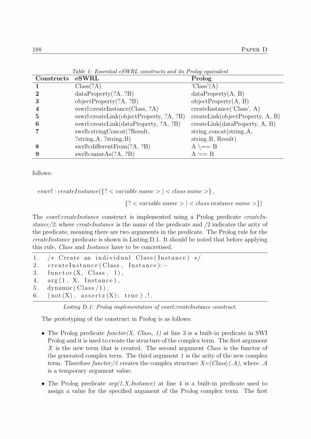
188 Paper D
Table 1: Essential eSWRL constructs and its Prolog equivalentConstructs eSWRL Prolog1 Class(?A) ’Class’(A)2 dataProperty(?A, ?B) dataProperty(A, B)3 objectProperty(?A, ?B) objectProperty(A, B)4 eswrl:createInstance(Class, ?A) createInstance(’Class’, A)5 eswrl:createLink(objectProperty, ?A, ?B) createLink(objectProperty, A, B)6 eswrl:createLink(dataProperty, ?A, ?B) createLink(dataProperty, A, B)7 swrlb:stringConcat(?Result, string concat(string A,
?string A, ?string B) string B, Result)8 swrlb:differentFrom(?A, ?B) A \== B9 swrlb:sameAs(?A, ?B) A == B
follows:
eswrl : createInstance({? < variable name > | < class name >} ,
{? < variable name > | < class instance name >})
The eswrl:createInstance construct is implemented using a Prolog predicate createIn-stance/2, where createInstance is the name of the predicate and /2 indicates the arity ofthe predicate, meaning there are two arguments in the predicate. The Prolog rule for thecreateInstance predicate is shown in Listing.D.1. It should be noted that before applyingthis rule, Class and Instance have to be concretised.
1 . /∗ Create an i n d i v i d u a l Class ( Ins tance ) ∗/2 . c r e a t e I n s t a n c e ( Class , In s tance ):−3 . func to r (X, Class , 1 ) ,4 . arg (1 , X, Ins tance ) ,5 . dynamic ( Class /1) ,6 . ( not (X) , a s s e r t z (X) ; t rue ) , ! .
Listing D.1: Prolog implementation of eswrl:createInstance construct.
The prototyping of the construct in Prolog is as follows:
• The Prolog predicate functor(X, Class, 1) at line 3 is a built-in predicate in SWIProlog and it is used to create the structure of the complex term. The first argumentX is the new term that is created. The second argument Class is the functor ofthe generated complex term. The third argument 1 is the arity of the new complexterm. Therefore functor/3 creates the complex structure X=〈Class〉( A), where Ais a temporary argument value;
• The Prolog predicate arg(1,X,Instance) at line 4 is a built-in predicate used toassign a value for the specified argument of the Prolog complex term. The first

3. Proposed Approach: eSWRL 189
argument 1 selects the first argument, the second argument X is the complexterm and the third argument Instance, which is the value instantiated to the firstargument in the complex term X. The resulting complex term created is X =〈Class〉(〈Instance〉);
• The Prolog predicate dynamic(Class/1). Dynamic/1 at line 5 is a built-in predicate,which informs the Prolog interpreter that the definition of the predicate Class maybe changed during execution;
• The construction at line 6 is (not(X), assertz(X); true),!. The assertz(X) predicateadds the resultant complex term X to the Prolog database and the construct ”!” iscalled a cut in Prolog, which prevents the Prolog rule from backtracking once thefact 〈Class〉(〈Instance〉) is added to the database.
The createLink construct is used to create a new tuple, which can be either objectproperty or data property instance. For the sake of brevity, if it does not cause unambi-guity, ”object (data) property” instead of ”object (data) property instance” will be used.The syntax of the createLink construct is as follows:
eswrl : createLink({? < variable name > | < property name >} ,
{? < variable name 1 > | < class instance name 1 >} ,
{? < variable name 2 > | < class instance name 2 >})
In Listing. D.2, Prolog definition of the createLink construct, which uses the samebuilt-in predicates functor/3 and arg/3. The resultant Prolog fact is in the form〈Link〉(〈Instance1〉, 〈Instance2〉).1 . /∗ Create a l i n k Link ( Instance1 , Ins tance2 ) ∗/2 . c r ea teL ink ( Link , Instance1 , Ins tance2 ):−3 . func to r (X, Link , 2 ) ,4 . arg (1 , X, Ins tance1 ) ,5 . arg (2 , X, Ins tance2 ) ,6 . dynamic ( Link /2) ,
Listing D.2: Prolog implementation of eswrl:createLink construct.
3.3 Execution semantic of eSWRL rules
The execution semantics of the eSWRL rules in this work is shown in Fig. reffig:paper4fig4.The execution follows a single pass iterative execution (SPIE) model where Y indicatesthe rule is enabled and N indicates the rule is not. This means each eSWRL rule will berepeated until it is not applicable. Once a rule is no longer enabled, the next rule is exe-cuted. There can be dependencies between the rules if a rule creates a Prolog fact that is

190 Paper D
used in the subsequent rule. It should be noted there are other execution models such assingle pass sequential execution model, cyclic sequential execution model, cyclic reverseexecution model etc. It is also possible to use more flexible logic to manage the rulesexecution, for example, control diagram from attributed programmed graph grammar[47].
Figure 2: Single Pass iterative Execution Semantics of eSWRL.
4 Case Study
4.1 Distributed bus protection
The case study distribution system used for model transformation in this paper is asimple distribution system introduced in [48] running decentralised protection and controlschemes. Fig. 3 shows the distribution system which consists of two transformers and fivedistribution feeders. Each transformer and feeders have their own Intelligent ElectronicDevices (IED). An example of a decentralised protection running on this distributionsystem is distributed bus protection and the operating sequence is as follows:
1. Each feeder and transformer protection IED (PIED) is running the overcurrentprotection scheme in Fig. 4. The current transformer (CT) LN TCtra is samplingthe current measurement at a fixed sampling rate. The CT measurement is thenpassed to the overcurrent protection LN PIOCa via the signal AmpSv instMag f ;
2. The PIOCa LN compares the received measurement against its internal overcurrentthreshold. If the measurement is over the internal threshold, the PIOCa will sendthe signal Op general to the trip conditioning LN PTRCa. The PIOCa LN alsoreceives the Tr general signal of the PTRCa LN from the other feeder PIEDs. Theexternal Tr general signal informs whether an overcurrent fault has been detectedon the other feeders;
3. When the PTRCa LN receives the Op general signal from the PIOCa LN, it sendsthe tripping signal Tr general to the circuit breaker (CB) LN XCBRa to operatethe CB. In addition, the Tr general signal is also sent to the other feeder andtransformer PIEDs. Sending the signal to the transformer and other feeders is partof the distributed bus protection. Since the transformer will also see the same fault,it will allow the transformer PIED to block itself from tripping its own CB.

4. Case Study 191
Figure 3: De-centralised bus protection in a simple distribution system [48].
Figure 4: Overcurrent protection on a single feeder IED.
4.2 Modelling of Semantic Message Passing Between LN
In the case study system, every feeder and transformer have its own PIED runningovercurrent protection for itself. In order to collectively perform decentralised protectionfor the whole system, peer-to-peer GOOSE messaging is used to exchange the signalsbetween the PIEDs as shown in Fig. 4. In the SCL description, only the message passing

192 Paper D
Table 2: Rule sets to automatically generate the complete automation systemRule sets Functionality0 Creating EnumeratedType with EnumType1 Creating StructureTypes with DATypes2 Creating StructureTypes with DOTypes3 Creating FBTypes from LNodeType with Interfaces4 Creating IEC 61499 system structure5 Creating FB instances in application6 Creating FB connections in application
between the IED devices (Inter-device) are captured. In an IEC 61499 control system,it is essential to know the message passing between the LNs in addition to the messagepassing between the devices. An approach to the modelling of message passing betweenLNs was introduced in [46]. In the work [46], all the message passing between LNsare represented as a graph. The graph representation is then translated to an ontologyrepresentation. The ontology class LNConnections is introduced in [46] to capture all themessage passing in the system. The data properties of the class are LNC from (SourceLN of the message), LNC to (Destination LN of the message), LNC name (Name of themessage) and LNC type (The data type of the message). This ontology model is thenadded to the source IEC 61850 ontology A-Box to add the LN to LN message passinginformation which is missing in the SCL description.
5 Model Transformation
5.1 Approaches to model transformation
There are two approaches which can be taken when transforming models from IEC 61850to IEC 61499. The first approach is to create all the artefacts in an IEC 61499 system.This includes creating the structured data types, the FBTypes, the System and theApplication. The required rule sets for this approach is shown in Table 2. Rule sets 0,1, 2 are used to create the structured datatypes. The ruleset 3 is used to create the FBtypes. The rulesets 4, 5 and 6 are used to create the IEC 61499 application with FBinstances and connections. The advantage of this approach is there is more flexibilityin defining the interfaces of the FBs. The disadvantage of this approach is the internalof the FBs, such as the Execution Control Chart (ECC) need to be created manuallyor automatically generated. Generating the ECCs introduces another step in the modeltransformation process, which is out of the scope of this paper.
The second approach is to create the IEC 61499 system only. This approach workswith the provision there already exists a library of FBs where the internal intelligenceof the LNs is already implemented. This is often the case where the IED vendors willprovide a library of implemented functions within the IED. This approach significantlyreduces the development effort since the only rule sets 4, 5 and 6 are applicable. The
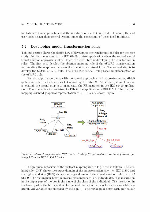
5. Model Transformation 193
limitation of this approach is that the interfaces of the FB are fixed. Therefore, the enduser must design their control system under the constraints of these fixed interfaces.
5.2 Developing model transformation rules
This sub-section shows the design flow of developing the transformation rules for the casestudy distribution system to its IEC 61499 control application when the second modeltransformation approach is taken. There are three steps in developing the transformationrules. The first is to develop the abstract mapping rule of the eSWRL transformationrepresenting the mappings between the domains in a visual form. The second step is todevelop the textual eSWRL rule. The third step is the Prolog-based implementation ofthe eSWRL rule.
The first step in accordance with the second approach is to first create the IEC 61499system structure with the ruleset 4 according to Table 2. After the system structureis created, the second step is to instantiate the FB instances in the IEC 61499 applica-tion. The rule which instantiates the FBs in the application is RULE 5 2. The abstractmapping-oriented graphical representation of RULE 5 2 is shown Fig. 5.
Figure 5: Abstract mapping rule RULE 5 2. Creating FBtype instances in the application forevery LN in an IEC 61850 LDevice.
The graphical notations of the abstract mapping rule in Fig. 5 are as follows. The left-hand side (LHS) shows the source domain of the transformation rule. i.e. IEC 61850 andthe right-hand side (RHS) shows the target domain of the transformation rule. i.e. IEC61499. The rectangular boxes represent class instances (i.e. individuals). The inscriptionin the upper part of the box is the name of the class of the individual. The inscription inthe lower part of the box specifies the name of the individual which can be a variable or aliteral. All variables are preceded by the sign ‘?’. The rectangular boxes with grey colour

194 Paper D
fill are the newly created class instances. The red dotted arrows and the associated textrepresent the newly created object properties. The red solid arrows and its associatedtext are the data properties. The blue coloured rectangles with rounded corners are thedata type values created by the transformation. It is assumed that the names used in therules are self-sufficient to determine their sense. Note that only the coloured elementsare created by the transformation rule. Under the SPIE execution model, each eSWRLrule executes every time at the different combinations of values of variables on the LHSas long as not all combinations are exhausted. The FBType instances in the applicationare created as follows:
1. For every LN in the selected LDevice, an equivalent FBType instance is createdwith the instance name of ?FB ;
2. The ?FB individual name is the concatenation of the string ”APP ” and the LNdata properties values ?LNprefix + ” ” + ?LNlnType + ” ” + ?LNinst ;
3. For each FB that is created, the data properties has FB Name and has FB typeare created indicating the name of FBType of the created FB;
4. The variable ?FBName for has FB Name data property value is the concatenationof the LN data properties values ?LNprefix + ” ” + ?LNlnType + ” ” + ?LNinst ;
5. The value of data property has FB type is the derived from the LN data propertyvalue ?LNlnType.
The second step is to develop the textual representation of the eSWRL rule as shownin Listing. D.3. Note that when describing the eSWRL rules, the denotation of a variablecan mean the value of the variable. For example, denotation ?LN means an instance ofthe LN class that is the value of the variable ?LN. At line 2, 3, 4 and 6, instances ofa LDevice, an Application, a SubAppNetwork and a LN are selected and stored in theirrespective variables ?Ldevice, ?Application, ?SubAppNetwork and ?LN. At line 5, objectproperty has SubAppNetwork is used to select the ?SubAppNetwork that is associatedwith the current ?Application. At line 6, object property has LN is used to select the?LN that is associated with the current ?LDevice. In lines 8, 9 and 10 data propertieshas lnType, has inst and has prefix of the ?LN is used to define variables ?LNlntype,?LNinst and ?LNprefix respectively. Lines 12 to 16 concatenates the LN data propertiesvalues to create the value for the FB data properties. At line 17, a new FB instanceis created with the name ?FB. At line 18, the object property has FB is created whichdetermines the association between the selected ?SubAppNetwork and the new ?FB. Lines19 and 20 creates the data properties has FB Name and has FB Type for the new ?FBwith the values ?FBName and ?LNlnType respectively.
1 . /∗ RULE 5 2 − Creat ing FB in s tance in Appl i cat ion ∗/2 . LDevice (? Ldevice ) ,3 . App l i ca t ion (? Appl i ca t ion ) ,4 . SubAppNetwork (? SubAppNetwork ) ,

5. Model Transformation 195
5 . has SubAppNetwork (? Appl icat ion , ?SubAppNetwork ) ,6 . LN(?LN) ,7 . has LN (? Ldevice , ?LN) ,8 . has lnType (?LN, ?LNlnType ) ,9 . h a s i n s t (?LN, ? LNinst ) ,10 . h a s p r e f i x (?LN, ? LNpref ix ) ,11 . −>12 . swrlb : s t r ingConcat (?N1 , ? LNprefix , ’ ’ ) ,13 . swrlb : s t r ingConcat (?N2 , ?N1 , ?LNlnType ) ,14 . swrlb : s t r ingConcat (?N3 , ?N2 , ’ ’ ) ,15 . swrlb : s t r ingConcat (?FBName, ?N3 , ? LNinst ) ,16 . swrlb : s t r ingConcat (?FB, ’APP ’ , ?FBName) ,17 . e swr l : c r e a t e I n s t a n c e (FB, ?FB) ,18 . e swr l : c r ea teL ink ( has FB , ?SubAppNetwork , ?FB) ,19 . e swr l : c r ea teL ink ( has FB Name , ?FB, ?FBName) ,20 . e swr l : c r ea teL ink ( has FB Type , ?FB, ?LNlnType ) .
Listing D.3: Textual representation of RULE 5 2 written in eSWRL.
The last step is to develop the Prolog implementation of RULE 5 2 as shown inListing. D.4. Comparing the eSWRL and the Prolog rule shows almost a one to one cor-respondence between the rules. At line 21, the Prolog predicate fail/0 is a built-in Prologpredicate, which will fail when encountered by Prolog as a goal. This forces Prolog tobacktrack due to the negation as failure property of Prolog ensuring the implementationof the SPIE execution scheme in Fig. 2. Line 22 is used to make always true executionof the rule.
1 . r u l e 5 2 :−2 . ’ LDevice ’ ( Ldevice ) ,3 . ’ Appl icat ion ’ ( App l i ca t ion ) ,4 . ’ SubAppNetwork ’ ( SubAppNetwork ) ,5 . has SubAppNetwork ( Appl icat ion , SubAppNetwork ) ,6 . ’LN’ (LN) ,7 . has LN ( Ldevice , LN) ,8 . has lnType (LN, LNlnType ) ,9 . h a s i n s t (LN, LNinst ) ,10 . h a s p r e f i x (LN, LNpref ix ) ,11 . /∗ −> ∗/12 . atom concat ( LNprefix , ’ ’ , N1) ,13 . atom concat (N1 , LNlnType , N2) ,14 . atom concat (N2 , ’ ’ , N3) ,15 . atom concat (N3 , LNinst , FBName) ,16 . atom concat ( ’APP ’ , FBName, FB) ,17 . c r e a t e I n s t a n c e ( ’FB’ , FB) ,18 . c r ea teL ink ( has FB , SubAppNetwork , FB) ,

196 Paper D
19 . c r ea teL ink ( has FB Name , FB, FBName) ,20 . c r ea teL ink ( has FB Type , FB, LNlnType ) ,21 . f a i l .22 . r u l e 5 2 .
Listing D.4: Prolog representation of RULE 5 2.
A snippet of the resultant Prolog database generated by RULE 5 2 is shown in List-ing. D.5, which shows only the LNs created for one LDevice. Five FB instances arecreated, including the object property has FB and the data properties has FB Nameand has FB Type. Note that since the resultant facts are stored in the same database asthe source facts, there are possibilities for conflicts, e.g. duplication of facts. However,this can be mitigated by designing the transformation rules in such a way to excludethe generation of conflicting, redundant and irrelevant facts and thus, minimising thepotential for conflicts. For example, to mitigate the potential for conflicts between theresultant and the source facts, one can ensure that the naming of the classes, data andobject properties between the two domains are different. In addition, namespaces can beadded as prefixes to Prolog facts to differentiate the facts between the two domains toavoid duplications.
1 . /∗ Resultant Prolog Database c rea ted by RULE 5 2∗/2 . /∗ Function Block In s tance s ∗/3 . ’FB’ ( ’ APP Fd1 LPHDa 1 ’ ) .4 . ’FB’ ( ’ APP Fd1 PIOCa 1 ’ ) .5 . ’FB’ ( ’ APP Fd1 PTRCa 1 ’ ) .6 . ’FB’ ( ’ APP Fd1 TCTRa 1 ’ ) .7 . ’FB’ ( ’ APP Fd1 XCBRa 1 ’ ) .8 . /∗ has FB Object Property ∗/9 . has FB ( ’ ST APP SubAppNetwork ’ , ’APP Fd1 LPHDa 1 ’ ) .10 . has FB ( ’ ST APP SubAppNetwork ’ , ’ APP Fd1 PIOCa 1 ’ ) .11 . has FB ( ’ ST APP SubAppNetwork ’ , ’APP Fd1 PTRCa 1 ’ ) .12 . has FB ( ’ ST APP SubAppNetwork ’ , ’APP Fd1 TCTRa 1 ’ ) .13 . has FB ( ’ ST APP SubAppNetwork ’ , ’APP Fd1 XCBRa 1 ’ ) .14 . /∗ FB Ins tance has FB Name Data Property ∗/15 . has FB Name ( ’ APP Fd1 LPHDa 1 ’ , ’Fd1 LPHDa 1 ’ ) .16 . has FB Name ( ’ APP Fd1 PIOCa 1 ’ , ’ Fd1 PIOCa 1 ’ ) .17 . has FB Name ( ’ APP Fd1 PTRCa 1 ’ , ’Fd1 PTRCa 1 ’ ) .18 . has FB Name ( ’ APP Fd1 TCTRa 1 ’ , ’Fd1 TCTRa 1 ’ ) .19 . has FB Name ( ’ APP Fd1 XCBRa 1 ’ , ’Fd1 XCBRa 1 ’ ) .20 . /∗ h a s I n t e r f a c e L i s t Object Property ∗/21 . has FB Type ( ’ APP Fd1 LPHDa 1 ’ , ’LPHDa’ ) .22 . has FB Type ( ’ APP Fd1 PIOCa 1 ’ , ’PIOCa ’ ) .23 . has FB Type ( ’ APP Fd1 PTRCa 1 ’ , ’PTRCa’ ) .24 . has FB Type ( ’ APP Fd1 TCTRa 1 ’ , ’TCTRa’ ) .25 . has FB Type ( ’ APP Fd1 XCBRa 1 ’ , ’XCBRa’ ) .

6. Results 197
Listing D.5: Code Snippet of the Prolog Database showing the Prolog facts created by theRULE 5 2.
After the FBs are instantiated in the IEC 61499 application, the next step is tocreate the logical connections between the instantiated FBs in the application. Rule set6 is used to create the logical connections and the abstract graphical representation ofRULE 6 1 is shown in Fig. 6. For each LNConnection instance, a Connection instanceis created for DataConnection and another Connection instance is also created for theaccompanying EventConnection. The Connection instance has two data properties. Thefirst data property is has Connection Source, which depicts the source of the connectionand the has Connection Destination depicts the target of the connection.
Figure 6: Abstract mapping rule RULE 6 1. Creating FB event and data connections in anIEC 61499 application.
The resultant FB network of the overcurrent protection Fig. 4 is shown in Fig. 7. TheINITO output event is connected to the INIT input event of the neighbouring FB toinitialise the FBs. The other event and data connections between FBs are derived fromthe protection schema in Fig. 4. The solid blue and grey lines show the event and dataconnections respectively within an IED device. The dotted blue and grey lines show theevent and data connections between the IED devices.
6 Results
A snapshot of the Simulink model of the case study distribution system is shown inFig. 8. The primary of the wye-connected transformer is connected to a Three-PhaseSource block running at 130kV at 50Hz. The secondary ones, which are connected

198 Paper D
Figure 7: A snippet of the automatically generated FB network of the overcurrent protection inFig. 4 in a single IED.
Figure 8: Snapshot of Simulink model showing the the power source and two distribution feeders.
to the distribution feeders, are running at 6.3kV. The green coloured subsystems arethe communication channels, which actuate the connected CBs. The yellowed colouredsubsystems send the measurements to the FB application.

6. Results 199
Figure 9: Resultant FB application for the case study system automatically generated usingeSWRL.

200 Paper D
The resultant FB network of the case study system is shown in Fig. 9. For each PIEDdevice, six FBs are generated as shown in Fig. 7. The generated FB application includesthe FB instances in all the PIED devices, the event/data connections between the FBsin a device and between the devices. To assess the correctness of the generated FBapplication, the FB application is connected to the model of the plant in a co-simulationenvironment [12] in a closed-loop manner. The co-simulation environment consists oftwo simulation platforms. Matlab Simulink is used to simulate the physical process ofthe distribution system and NxtStudio is used to simulate the distributed control logic.The two simulation platforms communicate via Ethernet using the UDP/IP protocol,which allows the Simulink model to send measurement data to the distributed controlapplication and vice versa with actuation trip signals from the control application to theSimulink model.
Figure 10: Current measurement of Transformer (top) and feeder 1 (bottom) during distributedbus protection.
The result of distributed bus protection is shown in Fig. 10. An overcurrent fault isinserted at Feeder 1 at time 0.08 by the step function at OC CB1. The PIEDs on Feeder1 and Transformer will both see the fault. However, the Transformer will block itselffrom tripping its CB since it receives messages from the Feeder 1 PIED indicating it hasdetected the fault at its Feeder. Thus the transformer PIED does not trip its CB and

7. Conclusions and Future Work 201
allows feeder 1 PIED to clear the fault.
7 Conclusions and Future Work
A methodology based on ontology transformation as part of the MDE approach to au-tomatically generate decentralised CPS automation control system is presented. Thetransformation rule language eSWRL is introduced and the constructs which enable thetransformation of ontology are presented. The presented methodology uses ontologies asthe source model and eSWRL is used to transform the source model to the target model,which is also an ontology. In this paper, the methodology was applied to demonstrate theapplicability of ontology transformation to automatically generate a complete substationautomation control system with signal connections in the automation control system.The proposed approach is demonstrated on a smart grid case study system where a for-mal description of the specification is used to automatically generate the control system.What is generated in the resulting control system is an IEC 61499 application with FB in-stances and the logical connections between the FBs. The methodology presented in thispaper can also be extended to other domains where automatic generation is applicablewhen there exists a source ontology.
Future work includes improving the first model transformation approach discussed insection V, subsection A, by also generating the internal of the FBs, which includes theECC and the algorithms of each FBs. The modelling of basic FB ECCs can be builton the refactoring work on ECCs in [49]. In addition, validation on the transformedtarget ontology can be introduced to ensure the target conforms to the pre-conditions,post-conditions and invariants imposed on the transformation are met [43, 44]. In thecontext of the case study application, it is worth exploring the possibility of reverse modeltransformation, that is generating a partial IEC 61850 specifications from an IEC 61499configuration.
References
[1] H. Gharavi, H. Chen, and C. Wietfeld, “Guest editorial special section on cyber-physical systems and security for smart grid,” IEEE Transactions on Smart Grid,vol. 6, no. 5, pp. 2405–2408, September 2015.
[2] E. Lee and S. A. Seshia, Introduction to Embedded Systems, A Cyber-Physical Sys-tems Approach, 2nd ed. MIT Press, 2017.
[3] X. Fang, S. Misra, G. Xue, and D. Yang, “Smart grid - 2014; the new and improvedpower grid: A survey,” IEEE Communications Surveys Tutorials, vol. 14, no. 4, pp.944–980, Fourth 2012.
[4] R. Chang, Y. Yuan, H. Lv, W. Yin, and S. X. Yang, “Selling the smart grid -2014;part 1: Why consumers must buy in for the smart grid to succeed,” IEEEConsumer Electronics Magazine, vol. 1, no. 2, pp. 24–31, April 2012.

202 Paper D
[5] Y. Yuan, R. Chang, H. Lv, W. Yin, and S. X. Yang, “Selling the smart grid-part2: How consumers will interact with the smart grid,” IEEE Consumer ElectronicsMagazine, vol. 1, no. 3, pp. 20–28, July 2012.
[6] V. Madani, R. Das, F. Aminifar, J. McDonald, S. S. Venkata, D. Novosel, A. Bose,and M. Shahidehpour, “Distribution automation strategies challenges and opportu-nities in a changing landscape,” IEEE Transactions on Smart Grid, vol. 6, no. 4,pp. 2157–2165, July 2015.
[7] “IEC 61850-6: Configuration description language for communication in electricalsubstations related to ieds,” International Standard, First Edition, Geneva, vol. 2,2012.
[8] “IEC 61499-1: Function blocks-part 1 architecture,” International Standard, FirstEdition, Geneva, vol. 1, 2012.
[9] V. Vyatkin, “Iec 61499 as enabler of distributed and intelligent automation: State-of-the-art review,” IEEE Transactions on Industrial Informatics, vol. 7, no. 4, pp.768–781, Nov 2011.
[10] S. Patil, V. Vyatkin, and B. McMillin, “Implementation of freedm smart grid dis-tributed load balancing using iec 61499 function blocks,” in IECON 2013 - 39thAnnual Conference of the IEEE Industrial Electronics Society, Nov 2013, pp. 8154–8159.
[11] G. Zhabelova, V. Vyatkin, and N. K. C. Nair, “Standard-based engineering anddistributed execution framework for intelligent fault management for freedm sys-tem,” in IECON 2011 - 37th Annual Conference of the IEEE Industrial ElectronicsSociety, Nov 2011, pp. 2724–2729.
[12] C. h. Yang, G. Zhabelova, C.-W. Yang, and V. Vyatkin, “Cosimulation environmentfor event-driven distributed controls of smart grid,” IEEE Transactions on IndustrialInformatics, vol. 9, no. 3, pp. 1423–1435, Aug 2013.
[13] N. Higgins, V. Vyatkin, N. K. C. Nair, and K. Schwarz, “Distributed power systemautomation with iec 61850, iec 61499, and intelligent control,” IEEE Transactionson Systems, Man, and Cybernetics, Part C (Applications and Reviews), vol. 41,no. 1, pp. 81–92, Jan 2011.
[14] nxtControl, “nxtstudio,” 2010. [Online]. Available: https://www.nxtcontrol.com
[15] I. Triplex, “Isagraf 6 workbench,” 2013. [Online]. Available:http://www.isagraf.com/index.htm
[16] G. Zhabelova and V. Vyatkin, “Multiagent smart grid automation architecture basedon iec 61850/61499 intelligent logical nodes,” IEEE Transactions on Industrial Elec-tronics, vol. 59, no. 5, pp. 2351–2362, May 2012.
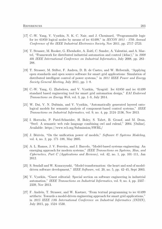
References 203
[17] C.-W. Yang, V. Vyatkin, N. K. C. Nair, and J. Chouinard, “Programmable logicfor iec 61850 logical nodes by means of iec 61499,” in IECON 2011 - 37th AnnualConference of the IEEE Industrial Electronics Society, Nov 2011, pp. 2717–2723.
[18] T. Strasser, M. Rooker, G. Ebenhofer, A. Zoitl, C. Sunder, A. Valentini, and A. Mar-tel, “Framework for distributed industrial automation and control (4diac),” in 20086th IEEE International Conference on Industrial Informatics, July 2008, pp. 283–288.
[19] T. Strasser, M. Stifter, F. Andren, D. B. de Castro, and W. Hribernik, “Applyingopen standards and open source software for smart grid applications: Simulation ofdistributed intelligent control of power systems,” in 2011 IEEE Power and EnergySociety General Meeting, July 2011, pp. 1–8.
[20] C.-W. Yang, G. Zhabelova, and V. Vyatkin, “Sysgrid: Iec 61850 and iec 61499standard based engineering tool for smart grid automation design,” EAI EndorsedTransactions on Energy Web, vol. 3, pp. 1–8, July 2014.
[21] W. Dai, V. N. Dubinin, and V. Vyatkin, “Automatically generated layered onto-logical models for semantic analysis of component-based control systems,” IEEETransactions on Industrial Informatics, vol. 9, no. 4, pp. 2124–2136, Nov 2013.
[22] I. Horrocks, P. Patel-Schneider, H. Boley, S. Tabet, B. Grosof, and M. Dean,“Swrl: A semantic web rule language combining owl and ruleml,” 2004. [Online].Available: https://www.w3.org/Submission/SWRL/
[23] J. Bezivin, “On the unification power of models,” Software & Systems Modeling,vol. 4, no. 2, pp. 171–188, May 2005.
[24] A. L. Ramos, J. V. Ferreira, and J. Barcelo, “Model-based systems engineering: Anemerging approach for modern systems,” IEEE Transactions on Systems, Man, andCybernetics, Part C (Applications and Reviews), vol. 42, no. 1, pp. 101–111, Jan2012.
[25] S. Sendall and W. Kozaczynski, “Model transformation: the heart and soul of model-driven software development,” IEEE Software, vol. 20, no. 5, pp. 42–45, Sept 2003.
[26] V. Vyatkin, “Guest editorial: Special section on software engineering in industrialautomation,” IEEE Transactions on Industrial Informatics, vol. 9, no. 4, pp. 2337–2339, Nov 2013.
[27] F. Andren, T. Strasser, and W. Kastner, “From textual programming to iec 61499artifacts: Towards a model-driven engineering approach for smart grid applications,”in 2015 IEEE 13th International Conference on Industrial Informatics (INDIN),July 2015, pp. 1524–1530.
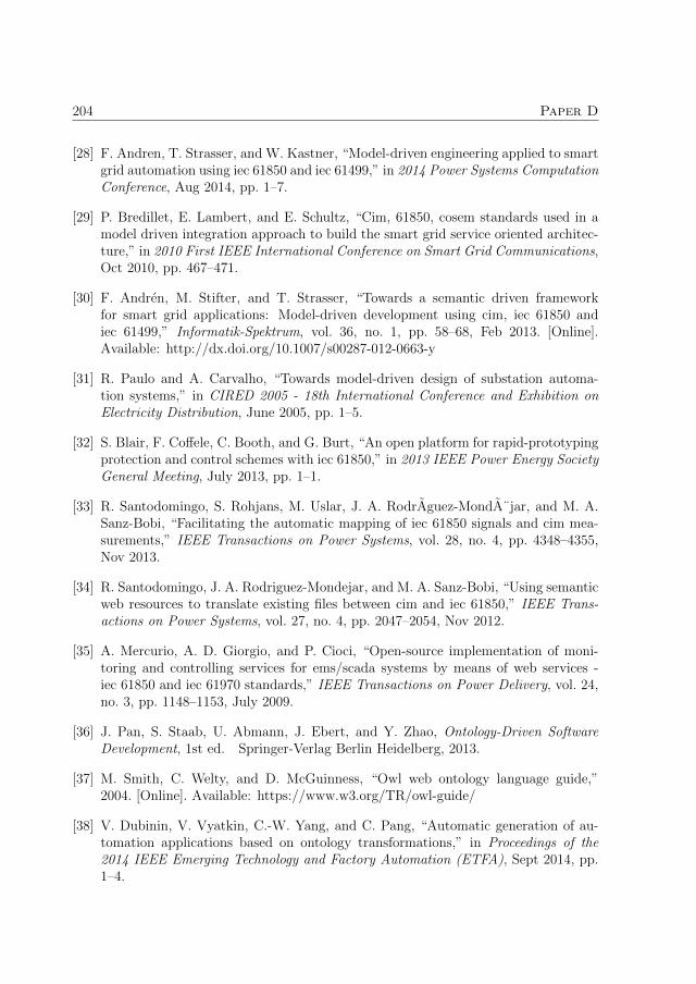
204 Paper D
[28] F. Andren, T. Strasser, and W. Kastner, “Model-driven engineering applied to smartgrid automation using iec 61850 and iec 61499,” in 2014 Power Systems ComputationConference, Aug 2014, pp. 1–7.
[29] P. Bredillet, E. Lambert, and E. Schultz, “Cim, 61850, cosem standards used in amodel driven integration approach to build the smart grid service oriented architec-ture,” in 2010 First IEEE International Conference on Smart Grid Communications,Oct 2010, pp. 467–471.
[30] F. Andren, M. Stifter, and T. Strasser, “Towards a semantic driven frameworkfor smart grid applications: Model-driven development using cim, iec 61850 andiec 61499,” Informatik-Spektrum, vol. 36, no. 1, pp. 58–68, Feb 2013. [Online].Available: http://dx.doi.org/10.1007/s00287-012-0663-y
[31] R. Paulo and A. Carvalho, “Towards model-driven design of substation automa-tion systems,” in CIRED 2005 - 18th International Conference and Exhibition onElectricity Distribution, June 2005, pp. 1–5.
[32] S. Blair, F. Coffele, C. Booth, and G. Burt, “An open platform for rapid-prototypingprotection and control schemes with iec 61850,” in 2013 IEEE Power Energy SocietyGeneral Meeting, July 2013, pp. 1–1.
[33] R. Santodomingo, S. Rohjans, M. Uslar, J. A. RodrAguez-MondA¨jar, and M. A.Sanz-Bobi, “Facilitating the automatic mapping of iec 61850 signals and cim mea-surements,” IEEE Transactions on Power Systems, vol. 28, no. 4, pp. 4348–4355,Nov 2013.
[34] R. Santodomingo, J. A. Rodriguez-Mondejar, and M. A. Sanz-Bobi, “Using semanticweb resources to translate existing files between cim and iec 61850,” IEEE Trans-actions on Power Systems, vol. 27, no. 4, pp. 2047–2054, Nov 2012.
[35] A. Mercurio, A. D. Giorgio, and P. Cioci, “Open-source implementation of moni-toring and controlling services for ems/scada systems by means of web services -iec 61850 and iec 61970 standards,” IEEE Transactions on Power Delivery, vol. 24,no. 3, pp. 1148–1153, July 2009.
[36] J. Pan, S. Staab, U. Abmann, J. Ebert, and Y. Zhao, Ontology-Driven SoftwareDevelopment, 1st ed. Springer-Verlag Berlin Heidelberg, 2013.
[37] M. Smith, C. Welty, and D. McGuinness, “Owl web ontology language guide,”2004. [Online]. Available: https://www.w3.org/TR/owl-guide/
[38] V. Dubinin, V. Vyatkin, C.-W. Yang, and C. Pang, “Automatic generation of au-tomation applications based on ontology transformations,” in Proceedings of the2014 IEEE Emerging Technology and Factory Automation (ETFA), Sept 2014, pp.1–4.

205
[39] B. N. Grosof, I. Horrocks, R. Volz, and S. Decker, “Description logicprograms: Combining logic programs with description logic,” in Proceedingsof the 12th International Conference on World Wide Web, ser. WWW’03. New York, NY, USA: ACM, 2003, pp. 48–57. [Online]. Available:http://doi.acm.org/10.1145/775152.775160
[40] V. Vassiliadis, J. Wielemaker, and C. Mungall, “Processing owl2 ontologies usingthea: An application of logic programming,” in Proceedings of the 6th InternationalConference on OWL: Experiences and Directions - Volume 529, ser. OWLED’09.Aachen, Germany, Germany: CEUR-WS.org, 2009, pp. 89–98. [Online]. Available:http://dl.acm.org/citation.cfm?id=2890046.2890056
[41] “Thea: A prolog library for owl2,” 2016. [Online]. Available:http://www.semanticweb.gr/thea/index.html
[42] “Swi-prolog,” 2016. [Online]. Available: http://www.swi-prolog.org/
[43] J. M. Almendros-Jimenez and L. Iribarne, “Transformation and validation with swrland owl of odm-based models,” in Proceedings of the 2Nd International Conferenceon Model and Data Engineering, ser. MEDI’12. Berlin, Heidelberg: Springer-Verlag,2012, pp. 103–115. [Online]. Available: http://dx.doi.org/10.1007/978-3-642-33609-6 11
[44] J. Almendros-Jimenez and L. Iribarne, “Model validation in ontology based transfor-mations,” 8th International Workshop on Automated Specification and Verificationof Web Systems, vol. 98, pp. 17–30, 2012.
[45] J. Almendros-Jimenez and L. Iribarne, “Ptl: A model transformation language basedon logic programming,” Journal of Logical and Algebraic Methods in Programming,vol. 85, no. 2, pp. 382–394, 2013.
[46] C.-W. Yang and V. Vyatkin, “Modelling of iec 61850 message passing for automaticgeneration of distributed control,” in IECON 2015 - 41st Annual Conference of theIEEE Industrial Electronics Society, Nov 2015, pp. 001 524–001 529.
[47] H. Bunke, “Attributed programmed graph grammars and their application toschematic diagram interpretation,” IEEE Transactions on Pattern Analysis and Ma-chine Intelligence, vol. PAMI-4, no. 6, pp. 574–582, Nov 1982.
[48] A. Apostolov and B. Vandiver, “Iec 61850 goose applications to distribution pro-tection schemes,” in 2011 64th Annual Conference for Protective Relay Engineers,April 2011, pp. 178–184.
[49] V. Vyatkin and V. Dubinin, “Refactoring of execution control charts in basic func-tion blocks of the iec 61499 standard,” IEEE Transactions on Industrial Informatics,vol. 6, no. 2, pp. 155–165, May 2010.

206

Paper E
On development of executionmodel for model transforming
distributed substation automationcontrol with ontology
Authors:Chen-Wei Yang, Valeriy Vyatkin and Victor Dubinin
Reformatted version of paper originally published in:2017 IEEE International Symposium on Industrial Electronics (ISIE)
c© 2017, IEEE, Reprinted with permission.
207

208

On development of execution model for model
transforming distributed substation automation
control with ontology
Chen-Wei Yang, Valeriy Vyatkin and Victor Dubinin
Abstract
The so-called Smart Grid is said to be enabled with bi-direction communication networksand energy flow. IEC 61850 is a substation communication standard which improves in-teroperability of the substation design. IEC 61499 is an automation standard whichcan be used for implementation of control in IEC 61850 models. This work is utilizingModel Driven Engineering techniques for substation automation systems, specifically us-ing ontology models to automatically generate IEC 61499 distributed automation controlsystems. eSWRL is the proposed ontology transformation and it is necessary to developan execution model for executing the transformation rules. This paper explores the use ofseveral execution semantic models for eSWRL and illustrates the use of the most suitableexecution model for the context of this work. In the case study, eSWRL rules are writtenusing the execution models discussed in this paper to generate a distributed automationcontrol library in IEC 61499.
1 Introduction
The future smart grid can be seen as a complex Cyber-Physical System [1] (CPS) withmany decomposed physical components interacting with distributed cyber processes. It isexpected that a smart grid will be integrated with modern digital communication and bi-directional power delivery in order to integrate renewable energy resources and increase inefficiency [2]. Implementation of such architecture implies a greater interaction betweenthe utilities and consumers with real-time data, changing consumers to prosumers activelyparticipating in the energy generation and distribution process [2]. There are various newchallenges in modelling a complex CPS system like a smart grid which includes modellingthe physical components and implementing a decentralized control system which is ableto interact between these cyber-physical components in a networked environment.
A practical step towards addressing these challenges is the industrial standard IEC61850. IEC 61850 is a substation automation standard which aims to provide interop-erability to communication between substations. IEC 61850 introduces object-orientedmodelling which de-composes a substation to small components. A decomposed com-ponent could be a physical component (i.e. a circuit breaker) and a cyber component(i.e. overcurrent function) in a substation. These components are modelled in IEC 61850
209

210 Paper E
as Logical Nodes (LN), a hierarchal information model which provides comprehensivemodelling of the component. However, in order to preserve interoperability, IEC 61850does not provide any means of logical implementation within these LN models.
IEC 61499 is an open standard and a reference architecture for distributed automationsystems [3] and it is capable of providing the implementation modelling of LNs. Thebuilding block of IEC 61499 is the Function Block (FB) artefacts which introduces objectorientation and decomposition to automation control systems. IEC 61499 is used infactory automation, material handling and recently, in the substation automation domain[4]. There are lots of synergies between the two standards in their approach to engineeringdistributed systems since both utilizes top-down design approach and object orientation.In addition, harmonizing or complementing the two standards addresses the informationand the control layer, two of the interoperability layers in the smart grid architectureproposed by the National Institute of Standards and Technology (NIST) [5].
This paper builds on the work in [6] where extended Semantic Web Rule Language(eSWRL) model transformation execution models are discussed for the purpose of modeltransformation for automation control. The paper is structured as follows. ChapterII outlines the related works. Chapter III discusses Model Driven Engineering usingontology models and the eSWRL transformation language. Chapter IV discusses theIEC 61850 information models. Chapter V presents the case study and usage of eSWRLrules written in a specific transformation execution model. Lastly, Chapter VI outlinesthe conclusion and future work.
2 Related Works
There are ongoing works in the smart grid automation research domain demonstratingthe viability of a solution which harmonizes IEC 61850 and IEC 61499. The intelligentLogical Node (iLN) [7, 8] architecture proposes the modelling of LNs as FBs and imple-menting local agent intelligence within each iLN. The iLN control is validated using aCo-Simulation environment [9] between Matlab Simulink and the FB development plat-form NxtStudio [10]. An open solution which utilizes open-source solution is shown in[11], which utilizes the open-source IEC 61499 development platform 4DIAC [12] andtakes a different approach in the modelling of the LNs in IEC 61499.
Model-driven engineering (MDE) is a technique where formal models are used toengineer the final solution. IEC 61850 introduced MDE in the form of Substation Con-figuration Languages (SCL). The SCL configuration language is used to model differentaspect of the engineering process captured in Extensible Markup Language (XML). Theoverall design is captured in the Substation Configuration Design (SCD) which containsthe overall system configuration, the overall communication configuration, LN definitionsand individual IED configurations.
There are existing works which utilize SCL as the source model for the purpose ofmodel transformation. SCD is used in [13] to transform LN models to control code in theC programming language. In [14], the Common Information Model (CIM) which consistsof the standards IEC 61970 and IEC 61968 are supplemented on top of IEC 61850 and

3. Ontology Model Transformation and Execution Semantics ofeSWRL 211
IEC 61499 to create a semantic driven approach to automatically generated automationcontrol. In [15], IEC 61850, CIM and Companion Specification for Energy Metering(COSEM) are used to develop a service-oriented solution to improve the management ofthe enterprise architecture for the smart grid by means of MDE. The MDE driven solutionSysGrid is proposed in [16] which utilizes SCL as the source models for automaticallytransforming distributed automation control.
There are limited numbers of MDE driven research works which explore the use ofontology as the means of modelling. The motivation of using ontology is due to the lackof relational semantics in the SCL XML models when used as the source model and toaddress the limitation in [16] where meaningful logical connections between FBs in anIEC 61499 application cannot be automatically transformed due to the lack of semanticsin SCL models. This work builds on the development of the ontology transformationlanguage eSWRL from [6, 17] by discussing the execution models of the transformationrules when using the eSWRL language.
3 Ontology Model Transformation and Execution Se-
mantics of eSWRL
3.1 Model Driven Engineering
MDE is widely used in software engineering [18, 19] for engineering large complex systems.The aim of MDE is to engineer solutions centred on the use of models. A model is anabstraction [20] of the system specification which can describe the structure, functionalityand behaviour of the system operating under in certain context. Models are formal if thevarious constructs within the model are linked via well-defined semantic description.
In MDE, there are two core models used in the engineering process. The first coremodel is the Platform Independent Model (PIM) model. The PIM model is the initialhigh-level abstraction model of the source domain which does not contain any informationor features of any target platform. The second core model is the Platform Specific Model(PSM). The PSM model is the platform-specific model which contains the implementationdetails and features of the target platform which can be further transformed to executablesoftware control codes for the target platform. In between these two core models aremodel transformation, which transforms the source PIM model to the target PSM model.The transformation of models is dictated by mappings or transformation specificationswhich governs the transformation of constructs between domains from the PIM model tothe PSM model.
The scope of this paper is in the transformation stage of MDE model transformation.The development of the PIM model and the development of the transformation rules areout of the scope of this paper.
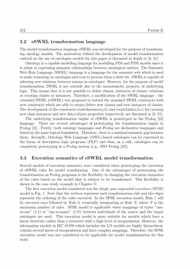
212 Paper E
3.2 eSWRL transformation language
The model transformation language eSWRL was developed for the purpose of transform-ing ontology models. The motivation behind the development of model transformationcentred on the use of ontologies models for this paper is discussed in depth in [6, 21].
Ontology is a capable modelling language for modelling PIM and PSM models since itis adept at expressing semantic relationships between ontological entities. The SemanticWeb Rule Language (SWRL) language is a language for the semantic web which is usedto make reasoning on ontologies and even to process them a little bit. SWRL is capable ofinferring new relations between axioms in ontologies. However, for the purpose of modeltransformation, SWRL is not suitable due to the monotonicity property of underlyinglogic. This means that it is not possible to delete classes, instances of classes, relationsor creating classes or instances. Therefore, a modification of the SWRL language - theextended SWRL (eSWRL) was proposed to extend the standard SWRL constructs withnew constructs which are able to create/delete new classes and new instances of classes.The development of the constructs createInstance(a,b) and createLink(a,b,c) for creatingnew class instances and new data/object properties respectively are discussed in [6, 21].
The underlying transformation engine of eSWRL is prototyped in the Prolog [22]language. There are several advantages of prototyping the transformation engine inProlog [21]. Firstly, both ontology languages and Prolog are declarative languages andbased on the same logical foundation. Therefore, there is a minimal semantic gap betweenthem. Secondly, Ontology Web Language (OWL)-based ontologies can be expressed inthe forms of description logic programs (DLP) and thus, as a rule, ontologies can becompletely prototyping in a Prolog system (e.g., SWI Prolog [23]).
3.3 Execution semantics of eSWRL model transformation
Several models of execution semantics were considered when prototyping the executionof eSWRL rules for model transforming. One of the advantages of prototyping thetransformation as Prolog programs is the flexibility in changing the execution semanticsof the rules based on the model that is subject to be transformed. This flexibility isshown in the case study example in Chapter V.
The first execution model considered was the Single pass sequential execution (SPSE)model in Fig. 1. Note that the vertices represent each transformation rule and the edgesrepresent the ordering of the rules executed. In the SPSE execution model, Rule 1 willbe executed once followed by Rule 2, eventually terminating at Rule N, where N is themaximum number of rules. SPSE model is applicable when mappings of types ”one-to-one” (1:1) or ”one-to-many” (1:N) between individuals of the source and the targetontologies are used. This execution model is more suitable for models which have alinear structure rather than a structure with a high level of encapsulation. However, theinformation models in IEC 61850 which includes the LN models are highly hierarchical,contain several layers of encapsulation and have complex mappings. Therefore, the SPSEexecution model was not considered to be applicable for model transformation for thiswork.

3. Ontology Model Transformation and Execution Semantics ofeSWRL 213
Figure 1: Single pass sequential execution model.
The second execution model is the Single pass iterative execution (SPIE) model asshown in Fig. 2, where iterations are introduced to each of the rules. The iterations ofeach rule are governed by the Enable Y value which enables the current rule to be iteratedand the Not Enable N value which disables iteration of the current rule and allows thenext rule in the chain to be executed. Therefore, a rule will continue to execute untilit is no longer applicable. Note that since the execution of each rule is independent ofeach other, there are situations where dependency between rules can occur when thesubsequent rules rely on Prolog facts created in the proceeding rules. Therefore, theorders in which the rules are executed are important when using this execution model.However, if the orders of the rules are written in a top-down approach, where the toplevel of the hierarchy is created first before continuing downwards, this limitation canbe minimized. SPIE model is more applicable in case of mappings of types N:1 or N:M.Moreover, for SPSE and SPIE models the following condition should be satisfied: ”Theexecution of any rule has not to generate facts stimulating the execution of any previousrule”.
Figure 2: Single pass iterative execution model, where Y - Rule is enabled, N - Rule is notenabled.
If this condition is not satisfied then it is reasonable to use a cyclic execution model,for example, Cyclic iterative execution (CIE) model in Fig. 3.
Figure 3: Cyclic iterative execution model.

214 Paper E
For the work described in this paper, SPIE is considered as the best execution modelto be used as the execution model for model transformation due to the hierarchal natureof both the source and the target models. The development of the rules which can bewritten to fit this model of execution is shown in Chapter V.
4 IEC 61850 Information Models
4.1 IEC 61850 logical nodes
For the purpose of interoperability, IEC 61850 introduces a hierarchical data model formodelling the power distribution systems in IEC 61850-7-4 [24] and object orientationto the data models in order to standardize the communication and data representationbetween devices. The highest level of the hierarchy is the Physical Device. Next leveldown is the Logical Devices. Within the Logical Devices are the LNs. The LNs arethe decomposition of the substation components which can either represent a functionalentity (e.g. overcurrent protection) or a physical entity (e.g. Circuit Breaker). EachLN follows a set template with standardized data objects (DO). However, each LN arecustomizable with mandatory and optional DOs in each LN.
4.2 Implementing control logic in logical nodes
The modelling of LN as FBs is based on the iLN concept and the implementation of logicwithin the FBs are discussed in [25]. When LNs are implemented as iLNs, the interfacesof the FBs list all the DOs of a LN as input and output variables. However, if youconsider LNs to be a consumer and producer of data, DOs which are consumed by theLN should not be an output variable and vice versa for data which is to be produced bythe LN. In this work, the determination of whether the DO is an input variable or outputvariable is dependent on the category in which the DO belongs to. The class definitionof the Current Transformer LN TCTR is shown in Fig. 4. In the TCTR LN, there arefour DO categories. These are Descriptions, Status Information, Measured and MeteredValues and Settings which are abbreviated to DE, ST, MX and SE respectively for thepurpose of this work. Both Description and Settings are considered to be input variablessince they are used to parameterize the LN. Status Information and Measured Values areconsidered to be output variables since this information is produced by the LN. Underthese categorization, the DOs EEName, ARth, HzRtg, Rat, Cor AngCor and CorCrv areinput variables. The DOs EEHealth, OpTmh and AmpSv are output variables.
5 Case Study: eSWRL Model Transformation
The sample iLN library to be automatically generated is the distributed protection libraryfor the distribution system in [26]. The overcurrent protection for a single feeder is shownin Fig. 5.

5. Case Study: eSWRL Model Transformation 215
Figure 4: IEC 61850 TCTR LN Class Definition [24].
Figure 5: Overcurrent protection on a single feeder IED.
In this simplified representation of the overcurrent scheme, there are four LNs. Thefirst is the current transformer LN TCTRa. The second is the Overcurrent LN PIOCa.The third is the trip conditioning LN PTRCa and the fourth is the circuit breaker LNXCBRa. The aim of the case study is to demonstrate how the SPIE execution semanticscan be used to automatically generate an iLN FB library. The interfaces of the FBs willbe generated according to the categorization of the LN DOs in Chapter IV, section B.

216 Paper E
Generating the internal Execution Control Chart (ECC) and algorithms of the FBs areout of the scope of this work.
5.1 Creating FBTypes from LNodeTypes
In an IEC 61850 logical device, all the LN instances are instantiated from a Logical NodeType (LNodeType). A LNodeType is an instantiable template of the LN which can beinstantiated in an IEC 61850 logical device with selections of Data objects derived fromthe LN class template in Fig. 4. In IEC 61499, equivalent artefacts exist in the formof FB Types and FB instances. There are three representation forms of eSWRL rules:graphical representation, textual eSWRL, and Prolog-based implementation. In thiswork, only the first and the third forms will be considered. The graphical representationof the first transformation rule showing the transformation mapping between LNodeTypeand FBType is shown in Fig. 6. The graphical representation is similar to the graphrewrite rules in typed attributed graph grammar [27] where the ontology elements arerepresented as vertices and arcs. The rules governing the creation of IEC 61499 FBTypefrom IEC 61850 LNodeType are as follows:
Figure 6: RULE 1 1: Creating FBType from LNodeType.
1. For every LNodeType, an equivalent FBType individual is created with the individ-ual name of ?LnodeID derived from the LNodeType has id data property value.

5. Case Study: eSWRL Model Transformation 217
2. The associated object property is an auxiliary object property which is added toallow the ease of access of the LNodeType in subsequent rules. The object propertylinks the LnodeType to its equivalent FBType counterpart.
3. For every FBType, a new data property has FBType Name is created with the value?LnodeID.
4. Every FBType has InterfaceList which contains the interface of the FBType. The in-terface includes input/ output events, input/output data and plugs/sockets adapters.The name of the InterfaceList is a string concatenation of ?LnodeID and ‘ InterfaceList’.
5. An object property has InterfaceList is created to link the FBType individual withthe InterfaceList individual.
1 . /∗ RULE 1 1 − Creat ing FBtype with LNodeType i n c l u d i n gFBInter face ∗/
2 . RULE 1 1:−3 . ’LNodeType ’ ( Lnode ) ,4 . ha s id ( Lnode , LnodeID ) ,5 . /∗ −> ∗/6 . c r e a t e I n s t a n c e ( ’FBType ’ , LnodeID ) ,7 . c r ea teL ink ( a s s o c i a t e , Lnode , LnodeID ) ,8 . c r ea teL ink ( has FBType Name , LnodeID , LnodeID ) ,9 . atom concat ( LnodeID , ’ I n t e r f a c e L i s t ’ , FbInte r f ace ) ,10 . c r e a t e I n s t a n c e ( ’ I n t e r f a c e L i s t ’ , FbInte r f ace ) ,11 . c r ea teL ink ( h a s I n t e r f a c e L i s t , LnodeID , FbInte r f ace ) ,12 . f a i l .13 . RULE 1 1 .
Listing E.1: Prolog implementation of RULE 1 1.
The Prolog implementation of RULE 1 1 is shown in Listing.E.1. At line 3, a LN-odeType is selected and stored in the variable ?Lnode. At line 4, the data propertyhas id of the LNodeType is selected and the value is stored in the variable ?LnodeID. Atline 6, a new FBType individual is created with the identifier ?LnodeID. At line 8, thehas FBType Name data property instance is created with the value ?LnodeID. At line 10,the InterfaceList individual is created which will list all the event and data inputs/out-puts of the FB. There is only one InterfaceList for a FBType and it is created at the sametime the FBType is created. At line 11, the has InterfaceList object property instanceis created linking the FBType individual and the InterfaceList individual. At line 12,the Prolog predicate is the fail/0 predicate. The fail/0 is a built-in Prolog predicatewhich will fail when encountered by Prolog as a goal. This will force Prolog to backtrackdue to the negation as failure property of Prolog. The fail/0 implements the rule periteration in the SPIE execution semantics. Without the fail/0 predicate, the executionwould follow the SPSE execution semantic where each rule is only executed once. Line

218 Paper E
13 is used to make always true execution of the rule. Therefore, RULE 1 1 will continueto iterate until it is not able to. In the context of the case study, RULE 1 1 will continueto execute until all LNodeType in the Prolog database are processed.
The Prolog database resulting from transformation RULE 1 1 is shown in Listing.E.2.In total, four FBTypes, TCTRa, PIOCa, PTRCa and XCBRa are created as shown inline 3 to line 6. In addition, the properties has FBType Name, has InterfaceList and thefour InterfaceList instances are generated.
1 . /∗ Resultant Prolog Database from RULE 1 1∗/2 . /∗ FBTypes ∗/3 . ’FBType ’ ( ’TCTRa’ ) .4 . ’FBType ’ ( ’ PIOCa ’ ) .5 . ’FBType ’ ( ’PTRCa’ ) .6 . ’FBType ’ ( ’XCBRa’ ) .7 . /∗ has FBType Name Data Property ∗/8 . has FBType Name ( ’TCTRa’ , ’TCTRa’ ) .9 . has FBType Name ( ’PIOCa ’ , ’PIOCa ’ ) .10 . has FBType Name ( ’PTRCa’ , ’PTRCa’ ) .11 . has FBType Name ( ’XCBRa’ , ’XCBRa’ ) .12 . /∗ I n t e r f a c e L i s t ∗/13 . ’ I n t e r f a c e L i s t ’ ( ’ TCTRa InterfaceList ’ ) .14 . ’ I n t e r f a c e L i s t ’ ( ’ PIOCa Inter faceLis t ’ ) .15 . ’ I n t e r f a c e L i s t ’ ( ’ PTRCa InterfaceList ’ ) .16 . ’ I n t e r f a c e L i s t ’ ( ’ XCBRa InterfaceList ’ ) .17 . /∗ h a s I n t e r f a c e L i s t Object Property ∗/18 . h a s I n t e r f a c e L i s t ( ’TCTRa’ , ’ TCTRa InterfaceList ’ ) .19 . h a s I n t e r f a c e L i s t ( ’PIOCa ’ , ’ PIOCa Inter faceList ’ ) .20 . h a s I n t e r f a c e L i s t ( ’PTRCa’ , ’ PTRCa InterfaceList ’ ) .21 . h a s I n t e r f a c e L i s t ( ’XCBRa’ , ’ XCBRa InterfaceList ’ ) .
Listing E.2: Prolog database showing the Prolog facts created by RULE 1 1.
After the FBTypes are created, the next step is to create the FB interfaces. The graph-ical representation of RULE 1 3 is shown in Fig. 7. Note the FBType class is linked withclasses EventInputs, Event and InputVars, these individuals are created in RULE 1 2.Note that RULE 1 2 are not shown in this paper since these individuals do not depend onthe LN class definitions. In addition, the standardized initialization input event (INIT )and initialization out (INITO) output event are also created in RULE 1 2. In RULE 1 3,a new VarDeclaration and a With individual is created for each DO in the LN. TheVarDeclaration class has two data properties, has VarDeclaration Name which describesthe name of the variable and has VarDeclaration Type, which describes the type of thevariable. Each VarDeclaration class individual which represents an input variable are as-sociated with the InputVars individual with the object property has VarDeclaration. TheWith individual indicates what variables are associated with what event. For the defaultLN class DOs, the input variables are associated with the Request (REQ) input event
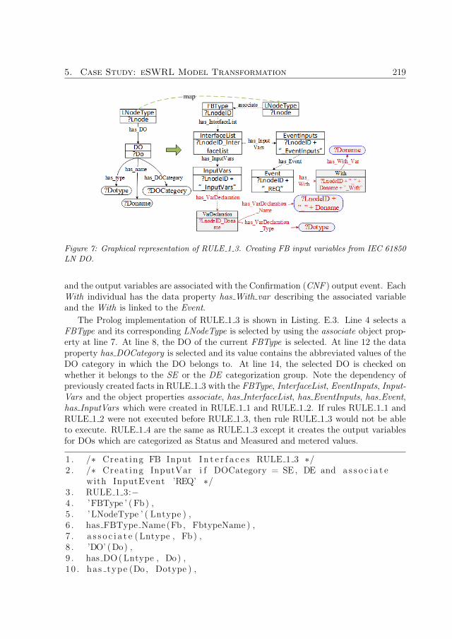
5. Case Study: eSWRL Model Transformation 219
Figure 7: Graphical representation of RULE 1 3. Creating FB input variables from IEC 61850LN DO.
and the output variables are associated with the Confirmation (CNF ) output event. EachWith individual has the data property has With var describing the associated variableand the With is linked to the Event.
The Prolog implementation of RULE 1 3 is shown in Listing. E.3. Line 4 selects aFBType and its corresponding LNodeType is selected by using the associate object prop-erty at line 7. At line 8, the DO of the current FBType is selected. At line 12 the dataproperty has DOCategory is selected and its value contains the abbreviated values of theDO category in which the DO belongs to. At line 14, the selected DO is checked onwhether it belongs to the SE or the DE categorization group. Note the dependency ofpreviously created facts in RULE 1 3 with the FBType, InterfaceList, EventInputs, Input-Vars and the object properties associate, has InterfaceList, has EventInputs, has Event,has InputVars which were created in RULE 1 1 and RULE 1 2. If rules RULE 1 1 andRULE 1 2 were not executed before RULE 1 3, then rule RULE 1 3 would not be ableto execute. RULE 1 4 are the same as RULE 1 3 except it creates the output variablesfor DOs which are categorized as Status and Measured and metered values.
1 . /∗ Creat ing FB Input I n t e r f a c e s RULE 1 3 ∗/2 . /∗ Creat ing InputVar i f DOCategory = SE , DE and a s s o c i a t e
with InputEvent ’REQ’ ∗/3 . RULE 1 3:−4 . ’FBType ’ ( Fb) ,5 . ’LNodeType ’ ( Lntype ) ,6 . has FBType Name (Fb , FbtypeName ) ,7 . a s s o c i a t e ( Lntype , Fb) ,8 . ’DO’ ( Do) ,9 . has DO ( Lntype , Do) ,10 . has type (Do , Dotype ) ,

220 Paper E
11 . has name (Do , Doname) ,12 . has DOCategory (Do , Docategory ) ,13 . a tom st r ing (Y, Docategory ) ,14 . member(Y, [ ’ SE ’ , ’DE’ ] ) ,15 . ’ I n t e r f a c e L i s t ’ ( FbInte r f ace ) ,16 . h a s I n t e r f a c e L i s t (Fb , FbInte r f ace ) ,17 . ’ EventInputs ’ ( Ei ) ,18 . has EventInputs ( FbInter face , Ei ) ,19 . ’ Event ’ ( Event ) ,20 . has Event ( Ei , Event ) ,21 . has Event Name ( Event , EventName ) ,22 . a tom st r ing (Z , EventName ) ,23 . Z == ’REQ’ ,24 . ’ InputVars ’ ( Iv ) ,25 . has InputVars ( FbInter face , Iv ) ,26 . /∗ −> ∗/27 . atom concat (FbtypeName , ’ ’ , N1) ,28 . atom concat (N1 , Doname , VarD) ,29 . c r e a t e I n s t a n c e ( ’ VarDeclarat ion ’ , VarD) ,30 . c r ea teL ink ( has VarDec larat ion , Iv , VarD) ,31 . c r ea teL ink ( has VarDeclaration Name , VarD , Doname) ,32 . c r ea teL ink ( has VarDeclarat ion Type , VarD , Dotype ) ,33 . atom concat (EventName , ’ ’ , N2) ,34 . atom concat (N2 , VarD , N3) ,35 . atom concat (N3 , ’ With ’ , With ) ,36 . c r e a t e I n s t a n c e ( ’ With ’ , With ) ,37 . c r ea teL ink ( has With , Event , With ) ,38 . c r ea teL ink ( has With Var , With , Doname) ,39 . f a i l .40 . RULE 1 3 .
Listing E.3: Prolog implementation of RULE 1 3.
The resultant FB for the LN TCTRa when the above rules are executed is shown inFig. 8. The INIT and INITO are events which are always created to parametrize thefunction block. The REQ input event is associated with the DOs which are under thecategory Description and Settings. Note that the variables Name Plate (NamPlt) andMode (Mod) are not in the TCTR class definition in Fig. 4. This is because both of thesetwo variables belong to the common LN which supplements all LN definitions, but are notshown in individual LN class definitions. The output event CNF is associated with theoutput variables from the Status and the Measured and Metered Values category. Notethat DOs Behavior (Beh) also belongs to the common LN. The REQ and CNF eventsare both created in RULE 1 2 and the LN class specific output and input variables arecreated in RULE 1 3 and RULE 1 4 respectively.

6. Conclusion 221
Figure 8: FB representation of automatically generated TCTR LN.
6 Conclusion
The aim of this paper is to discuss the execution semantics for the eSWRL transformationlanguage to automatically transform substation specifications to distributed automationcontrol. eSWRL was developed for the purpose of enabling MDE model transformationfor ontology models. The resultant automation control is based on the iLN architecturewhere each IEC 61850 LN is transformed to an equivalent representation in IEC 61499FB. Due to the high level of encapsulation in the LN information models, the executionmodel which was used for generating the case study automation control library was theSingle Pass Iterative Execution Model. The SPIE model iterates each rule until it canno longer execute. This execution model takes into account a dependency between rulesand therefore, the order in which the rules are executed is important. In this case study,the SPIE execution model was used to generate an FB library with FB interfaces basedon the categorization of DOs. For future work, this execution model could be used togenerate a full FB application with networks of FB to create the overcurrent protectionscheme in Fig. 5. In addition, generating the internals of the FBs which includes theECC and the algorithms will also be part of the future work. One direction for modellingof basic FB ECC can be based on the refactoring work on ECCs in [28].
References
[1] H. Gharavi, H. Chen, and C. Wietfeld, “Guest editorial special section on cyber-physical systems and security for smart grid,” IEEE Transactions on Smart Grid,vol. 6, no. 5, pp. 2405–2408, September 2015.
[2] X. Fang, S. Misra, G. Xue, and D. Yang, “Smart grid - 2014; the new and improvedpower grid: A survey,” IEEE Communications Surveys Tutorials, vol. 14, no. 4, pp.944–980, Fourth 2012.

222 Paper E
[3] “IEC 61499-1: Function blocks-part 1 architecture,” International Standard, FirstEdition, Geneva, vol. 1, 2012.
[4] V. Vyatkin, “Iec 61499 as enabler of distributed and intelligent automation: State-of-the-art review,” IEEE Transactions on Industrial Informatics, vol. 7, no. 4, pp.768–781, Nov 2011.
[5] NIST, “Nist framework and roadmap for smart grid interoperability standards, re-lease 3.0,” 2014. [Online]. Available: http://www.nist.gov/smartgrid/upload/NIST-SP-1108r3.pdf
[6] C.-W. Yang, V. Vyatkin, A. Mousavi, and V. Dubinin, “On automatic generation ofiec61850/iec61499 substation automation systems enabled by ontology,” in IECON2014 - 40th Annual Conference of the IEEE Industrial Electronics Society, Oct 2014,pp. 3577–3583.
[7] N. Higgins, V. Vyatkin, N. K. C. Nair, and K. Schwarz, “Distributed power systemautomation with iec 61850, iec 61499, and intelligent control,” IEEE Transactionson Systems, Man, and Cybernetics, Part C (Applications and Reviews), vol. 41,no. 1, pp. 81–92, Jan 2011.
[8] G. Zhabelova and V. Vyatkin, “Multiagent smart grid automation architecture basedon iec 61850/61499 intelligent logical nodes,” IEEE Transactions on Industrial Elec-tronics, vol. 59, no. 5, pp. 2351–2362, May 2012.
[9] C. h. Yang, G. Zhabelova, C.-W. Yang, and V. Vyatkin, “Cosimulation environmentfor event-driven distributed controls of smart grid,” IEEE Transactions on IndustrialInformatics, vol. 9, no. 3, pp. 1423–1435, Aug 2013.
[10] nxtControl, “nxtstudio,” 2010. [Online]. Available: https://www.nxtcontrol.com
[11] T. Strasser, M. Stifter, F. Andren, D. B. de Castro, and W. Hribernik, “Applyingopen standards and open source software for smart grid applications: Simulation ofdistributed intelligent control of power systems,” in 2011 IEEE Power and EnergySociety General Meeting, July 2011, pp. 1–8.
[12] T. Strasser, M. Rooker, G. Ebenhofer, A. Zoitl, C. Sunder, A. Valentini, and A. Mar-tel, “Framework for distributed industrial automation and control (4diac),” in 20086th IEEE International Conference on Industrial Informatics, July 2008, pp. 283–288.
[13] S. M. Blair, F. Coffele, C. D. Booth, and G. M. Burt, “An open platform for rapid-prototyping protection and control schemes with iec 61850,” IEEE Transactions onPower Delivery, vol. 28, no. 2, pp. 1103–1110, April 2013.
[14] F. Andren, M. Stifter, and T. Strasser, “Towards a semantic driven frameworkfor smart grid applications: Model-driven development using cim, iec 61850 and

References 223
iec 61499,” Informatik-Spektrum, vol. 36, no. 1, pp. 58–68, Feb 2013. [Online].Available: http://dx.doi.org/10.1007/s00287-012-0663-y
[15] P. Bredillet, E. Lambert, and E. Schultz, “Cim, 61850, cosem standards used in amodel driven integration approach to build the smart grid service oriented architec-ture,” in 2010 First IEEE International Conference on Smart Grid Communications,Oct 2010, pp. 467–471.
[16] C.-W. Yang, G. Zhabelova, and V. Vyatkin, “Sysgrid: Iec 61850 and iec 61499standard based engineering tool for smart grid automation design,” EAI EndorsedTransactions on Energy Web, vol. 3, pp. 1–8, July 2014.
[17] C.-W. Yang and V. Vyatkin, “Modelling of iec 61850 message passing for automaticgeneration of distributed control,” in IECON 2015 - 41st Annual Conference of theIEEE Industrial Electronics Society, Nov 2015, pp. 001 524–001 529.
[18] J. Bezivin, “On the unification power of models,” Software & Systems Modeling,vol. 4, no. 2, pp. 171–188, May 2005.
[19] A. L. Ramos, J. V. Ferreira, and J. Barcelo, “Model-based systems engineering: Anemerging approach for modern systems,” IEEE Transactions on Systems, Man, andCybernetics, Part C (Applications and Reviews), vol. 42, no. 1, pp. 101–111, Jan2012.
[20] J. Ludewig, “Models in software engineering – an introduction,” Software andSystems Modeling, vol. 2, no. 1, pp. 5–14, Mar 2003. [Online]. Available:http://dx.doi.org/10.1007/s10270-003-0020-3
[21] V. Dubinin, V. Vyatkin, C.-W. Yang, and C. Pang, “Automatic generation of au-tomation applications based on ontology transformations,” in Proceedings of the2014 IEEE Emerging Technology and Factory Automation (ETFA), Sept 2014, pp.1–4.
[22] C. M. William Clocksin, Programming in Prolog. Springer-Verlag Berlin Heidelberg,2003.
[23] “Swi-prolog,” 2016. [Online]. Available: http://www.swi-prolog.org/
[24] “IEC 61850-7: Basic communication structure - compatible logical node classes anddata object classes,” International Standard, First Edition, Geneva, 2009.
[25] C.-W. Yang, V. Vyatkin, N. K. C. Nair, and J. Chouinard, “Programmable logicfor iec 61850 logical nodes by means of iec 61499,” in IECON 2011 - 37th AnnualConference of the IEEE Industrial Electronics Society, Nov 2011, pp. 2717–2723.
[26] A. Apostolov and B. Vandiver, “Iec 61850 goose applications to distribution pro-tection schemes,” in 2011 64th Annual Conference for Protective Relay Engineers,April 2011, pp. 178–184.

224
[27] H. Ehrig, K. Ehrig, U. Prange, and G. Taentzer, Fundamentals of Algebraic GraphTransformation (Monographs in Theoretical Computer Science. An EATCS Series).Secaucus, NJ, USA: Springer-Verlag New York, Inc., 2006.
[28] V. Vyatkin and V. Dubinin, “Refactoring of execution control charts in basic func-tion blocks of the iec 61499 standard,” IEEE Transactions on Industrial Informatics,vol. 6, no. 2, pp. 155–165, May 2010.

Paper F
On Requirements-driven Design ofDistributed Smart Grid
Automation Control
Authors:Chen-Wei Yang and Valeriy Vyatkin
Reformatted version of paper originally published in:IEEE 14th International Conference on Industrial Informatics (INDIN) 2017
c© 2017, IEEE, Reprinted with permission.
225

226

On Requirements-driven Design of Distributed
Smart Grid Automation Control
Chen-Wei Yang and Valeriy Vyatkin
Abstract
This paper proposes a novel method of modelling requirements for smart grid automationsystems that fit and complement the leading standards used for software development insmart grid: IEC 61850 and IEC 61499. Ontological representation is used to formallymodel the systems requirements and the integration of the requirement modelling to beused in conjunction with IEC 61850 specifications and IEC 61499 implementation. Theproposed model is illustrated on a case study presented by the CIGRE working groupwhere the system requirement in natural language was firstly modelled in ontology, thenimplemented in IEC 61499. Lastly, the resulting IEC 61499 control system was testedand validated against the system requirement by signal testing of the end control system.
1 Introduction
Cyber-physical systems (CPS) are a collection of physical and computing processes inter-acting via a communication network. The Smart Grid is an example of a complex CPS.[1] with many distributed physical components interacting with distributed computingdevices and processes. The interactions between the physical and the logical processes areenabled with the introduction of digital communication [2] and bi-directional energy flow[3] in the smart grid. The physical components of a smart grid are made up of sensorsequipment which measures telemetry measurements such as voltages, currents and actu-ation equipment such as circuit breakers or switches for protection or control processes.The logical processes of a smart grid are made up of protection and control servicesrunning across the entire smart grid. Examples of protection services include fault andsafety management services and example of control processes includes energy and smartload management services. These logical processes are traditionally implemented onsingular intelligent electronic devices (IED). However, with the greater integration of re-newable energy resources and the greater interaction between the utilities and consumers,a centralized control architecture will no longer be sufficient. Therefore, in a smart gridarchitecture where the physical and the logical entities becomes more distributed and lesscentralized, there is a need to addresses the new design challenges of the emerging smartgrid with the shift in infrastructure from centralized to distributed and this applies toboth the physical and the logical component of the smart grid. Example of the designchallenges includes the need of modelling the distributed physical architecture, modelling
227

228 Paper F
of the distributed logical process and interoperable communication network between themyriads of independent physical and logical processes.
On the automation side, IEC 61499 is an industrial standard which provides a ref-erence architecture for designing and modelling of distributed control systems [4]. IEC61499 is adept at modelling modular logical process for distributed control systems withbasic modelling artefacts known as function blocks (FB). IEC 61499 introduces object ori-entation and top-down design approach to the modelling of automation control systems.IEC 61499 is widely adopted in other automation domains such as material handling, fac-tory automation and building automation systems [5]. In addition, IEC 61499 also beenused to smart grid applications where it is used to model the IEC 61850 specificationsfor the automation system [6, 7].
IEC 61850 is a substation automation standard with the aim of introducing communi-cation interoperability to distributed substation systems. IEC 61850 introduces the con-cept of logical nodes (LN) which models physical (e.g. primary equipment) and functional(e.g. protection functions) specifications and each LN has a predefined dataset that isnecessary to model the said function or physical specification. Interoperability is achievedby standardizing the communication interface and the communication protocols withinthe substation. In addition to communication interoperability, IEC 61850 also introduceslife cycle modelling of substations by means of the Substation Configuration Language(SCL) [8]. The SCL models cover the design life cycle from the specification stage to thetesting stage as shown in Fig 1. This introduces a pathway for utilizing model-drivenengineering (MDE) design techniques in the design of IEC 61850 based control systems.However, the SCL only introduces MDE at the specification level, whereas engineeringlifecycle begins at the requirement level as illustrated in Fig 1. Therefore, there is a needfor the ability to formally model system requirements that can lead to the design flowspecified in the SCL specifications as requirements engineering is vital in the design ofthe smart grid Information and Communication Technologies (ICT) infrastructure [9].
System requirements are typically written in natural languages. However, naturallanguage is not easily understandable or interpretable by machines and is also prone toambiguities in the human interpretation, which could be catastrophic and costly if dis-covered deep in the design process. Formal modelling of system requirements can revealthese ambiguities early and create a format which is machine readable and therefore,can be integrated into the IEC 61850 design flow and used in conjunction with the SCLspecifications.
The scope of the paper covers the formal modelling of substation system requirementsusing ontology models for the semantic web, the implementation of the formal require-ment in IEC 61499 using IEC 61850 specifications and lastly, the validation of the IEC61499 control system against the system requirement.
The paper is structured in the following way. Section II discusses the related works inrequirement engineering in automation systems, Section III defines the ontology modelfor the modelling of the requirements. Section IV introduces the case study distributedsystem from CIGRE which is used to illustrate the proposed modelling process. Thissection covers the modelling of one of the system requirement in ontology, the imple-
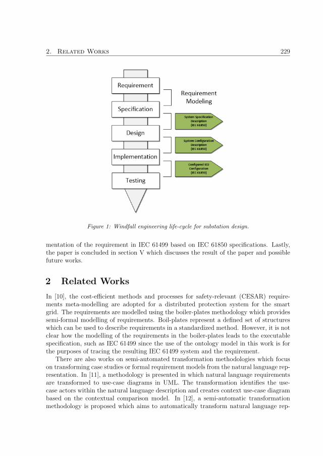
2. Related Works 229
Figure 1: Windfall engineering life-cycle for substation design.
mentation of the requirement in IEC 61499 based on IEC 61850 specifications. Lastly,the paper is concluded in section V which discusses the result of the paper and possiblefuture works.
2 Related Works
In [10], the cost-efficient methods and processes for safety-relevant (CESAR) require-ments meta-modelling are adopted for a distributed protection system for the smartgrid. The requirements are modelled using the boiler-plates methodology which providessemi-formal modelling of requirements. Boil-plates represent a defined set of structureswhich can be used to describe requirements in a standardized method. However, it is notclear how the modelling of the requirements in the boiler-plates leads to the executablespecification, such as IEC 61499 since the use of the ontology model in this work is forthe purposes of tracing the resulting IEC 61499 system and the requirement.
There are also works on semi-automated transformation methodologies which focuson transforming case studies or formal requirement models from the natural language rep-resentation. In [11], a methodology is presented in which natural language requirementsare transformed to use-case diagrams in UML. The transformation identifies the use-case actors within the natural language description and creates context use-case diagrambased on the contextual comparison model. In [12], a semi-automatic transformationmethodology is proposed which aims to automatically transform natural language rep-

230 Paper F
resentation of requirements to boiler-plates which are used for requirement formalismsince they support automated requirement analysis and is a semi-guided representationof the natural language requirement. The transformation is aided using domain ontol-ogy to correct typographic errors in natural language. The use of ontology is to correcttypography errors in the transformation and acts as a reference dictionary whereas, inthis paper, the ontology is used to formally model the requirement itself.
In [13], a method to automatically generate test cases from system requirement forCPS system based on model-driven engineering (MDE) technique is proposed. The pro-posed methodology uses various linked ontology models in the whole design chain in orderto trace the development of the system at each step of the design process.
In summary, there are existing works on the application and modelling of systemrequirements in the research field. Within the smart grid domain, the formal modellingof system requirements is still lacking. This paper adopts the use of ontology for mod-elling system requirements for smart grid applications and focuses on the integration ofrequirement engineering to IEC 61850.
3 Requirement Modeling in Ontology
3.1 Motivation
The motivation behind this work arose from the CIGRE taskforce 5.02 meeting in June2016 in Paris where the aim of the discussion was to examine the existing methods whichare best suited for the modelling of functional requirements which can be an additive tothe IEC 61850 design chain and the testing of the system requirement.
It is important at this stage to make a clear distinction of the differences betweenrequirement and specification to illustrate why IEC 61850 is not considered a require-ment modelling language. A requirement describes a behaviour or role of the system andhence, describes WHAT the system needs. An example of a system requirement is asfollows:
Transformer should be tripped during overload currents superior to 120 percent onany of its coils.
Which defines a certain behaviour or role the system must perform with no inklingof how this role can be implemented. A specification defines HOW the requirement canbe implemented. An example of a specification with respect to the requirement above isas follows:
An overcurrent protection can be implemented on the primary and secondary side ofthe transformer to detect the overload.
Which specifies the implementation of the overcurrent protection function on both theprimary and the secondary side of the transformer to detect the overload. This specifica-

3. Requirement Modeling in Ontology 231
tion can be modelled in IEC 61850 with the LNs Protection Instantaneous Overcurrent(PIOC) for overcurrent protection function. It is not possible to model requirements inIEC 61850 since the LN modelling artefacts fall under the category of specification defi-nition rather than requirements since the LNs model a certain functionality or physicalequipment.
In addition to the modelling of the system requirement, it is also paramount to be ableto validate the correctness of the end system with respect to the initial design requirementand the most common software testing technique that is used for validating requirementin black box testing. IEC 61499 can model the specification, the implementation andblack box testing of the implemented control system. There are existing research workswhich implements IEC 61850 specifications using IEC 61499 [6, 14, 15]. IEC 61499 isused as the modelling and implementation language for system requirement, IEC 61850specification and validation of the research work in this paper.
3.2 Modeling requirements in ontology
Ontology is a modelling language for the semantic web which is adept at defining theknowledge of a domain with concepts and the relationships between the concepts. Theadvantages of modelling requirements using ontology models include:
• Defining the individual statement within a requirement and how these componentsare related to each other;
• Forcing the requirement engineers to explicitly state each statement in the require-ment to avoid all ambiguities as illustrated in the case study in section IV;
• Can be queried with query languages such as semantic web rule language (SWRL)or SPARQL inferencing notation (SPIN) for resolving ambiguities and conflicts innatural language based requirements through ontology reasoning;
• Can be interpreted by machines with standard representation such as resourcedescription framework (RDF) and extensible markup language (XML).
In addition, ontology modelling are used extensively in IEC 61499 [16] based researchwork and IEC 61850 [17, 18] research work.
The ontology model of the Requirement domain and its concept are defined as:
Requirement ≡ Condition ∪ Action ∪ TimingRequirement
Where Requirement is the main domain under the root node of the ontology. Con-dition, Action and TimingRequirement are all concepts under the Requirement domainlinked by the object properties as shown in Fig 2. The square boxes with a yellow circularsymbol are the class concepts and the dashed arrows between the class concepts are theobject properties when modelled in Protege [19].

232 Paper F
Figure 2: Requirement domain and its concepts.
The Requirement domain contains one data property and three object properties. Thenaming convention of the properties are as follows: The object properties are defined asHas 〈objectPropertyName〉 and the data objects are defined as has 〈dataPropertyName〉.
The data property has name contains the name of the Requirement and the cardinal-ity is exactly 1:
(= 1 has name)
The object properties Has Action, Has Condition and Has TimingRequirement indi-cates the number of Actions, Conditions and Timing Requirement of the Requirementand the cardinality for the object properties are all at minimum 0:
(≥ 0 Has Condition ∩ ≥ 0 Has Action ∩ ≥ 0 Has T imingRequirement)
The first concept under the domain Requirement is TimingRequirement, which definesthe timing requirement. There can be timing requirements at different levels of therequirement, be it at the level of conditions, actions or the requirement itself. Theconcept TimingRequirement has one object property and two data properties.
The data properties are has name and has description, which describes the name ofthe timing requirement and the description of the timing requirement respectively. Thecardinality of both data properties is exactly 1:
(= 1 has name ∩ = 1 has description)
The object property of the concept TimingRequirement is Has TimingParameter link-ing to the concept TimingParameter as shown in Fig 3. The cardinality for Has TimingParameter

3. Requirement Modeling in Ontology 233
is exactly 1:
(= 1 Has T imingParameter)
Figure 3: TimingRequirement and its associated concepts.
The concept TimingParameter has two data properties which are has at least andhas within providing the timing constraint of the timing requirement. The has at leastdata property specifies the minimum quantity of time in which the condition, actionor the requirement must elapse. The has within data property specifies the maximumquantity of time in which the condition, action or the requirement must elapse within.Both data properties have a cardinality of 1.
(= 1 has at least ∪ = 1 has within)
The second concept under the domain Requirement is condition, which outlinesthe conditions of the requirement. The condition concept has two data properties,has description and has name which describes the condition and the name of the condi-tion respectively. The cardinality of the data properties is exactly 1:
(= 1 has name ∩ = 1 has description)
The object properties of the concept condition are Has TimingRequirement and Has Signalswhich associates condition with the concepts TimingRequirement and Signals as shownin Fig 4. The cardinality of both these object properties are at minimum 0:
(≥ 0 Has T imingRequirement ≥ 0 Has Signals)
The concept Signals defines the signals for the conditions, and actions. The conceptSignal has two data properties, has input signal and has output signal which defines theinput signal and the output signals respectively. The cardinality of these two data prop-erties are at minimum 0:

234 Paper F
Figure 4: Condition and its associated concepts.
(≥ 0 has input signal ∩ ≥ 0 has output signal)
The last concept under the Requirement domain is Action. The Action concept hasthe same data properties and object properties to that of the condition concept. Thedata properties are has description and has name with cardinality of exactly 1:
(= 1 has name ∩ = 1 has description)
The two object properties are Has TimingRequirement and Has Signals which asso-ciates the Action concept with the concepts TimingRequirement and Signal respectivelyas shown in Fig 5.
Figure 5: Action and its associated concepts.

4. Case Study 235
4 Case Study
4.1 A simple distribution system
The case study that will be a simple distribution system with three requirements to bemodelled as shown in Fig 6 was presented during the CIGRE taskforce meeting. There isa transformer TR1 with two current transformers, CT1 and CT2 measuring the primaryand the secondary current of the transformer. On the primary side, there are two switchesSW11 and SW12 along with a circuit breaker BRK1. On the secondary side, there arealso two switches SW21 and SW22 along with a circuit breaker BRK2.
Figure 6: Simple distribution system.
4.2 System requirements in natural language
The most readily understandable form of requirements is natural language. The threerequirements which will be used for this case study as described in natural languages areas follows:
1. Transformer TR1 should be tripped during overload currents superior to 120 percenton any of its coils that stays for at least 50ms in no more than 100ms.
2. Opening or closing of switches SW11 and SW12 shall be blocked whenever breakerBRK1 stays closed.
3. Any unauthorized access to the automation or protection system shall be detected,alarmed, recorded and signalled to the operator in no more than 1 min after itsdetection.
Although requirements in natural language can be readily interpreted by domainpractitioners, ambiguity can still occur and an example of this is requirement 1 pertainingto the timing constraint ”no more than 100ms”. There are two ways in which thiscan be interpreted. The first interpretation is that the tripping of Transformer TR1should be completed within 100ms and this does not include the detection time. Thismeans that the timing constraint is an action level timing constraint according to theontology definition. The second interpretation is that the process of overload detectionand tripping must all occur within 100ms and this means the timing constraint is arequirement level timing constraint. Modelling the requirements in an ontology canclean up these ambiguities and correctly define the requirements.

236 Paper F
4.3 Modeling in ontology
Each primary equipment in the case study system can be modelled as signals either asthe type BOOLEAN or INTEGER. For all switches SW11, SW12, SW21 and SW22, theSWITCH.pos and SWITCH.act of type BOOLEAN are defined and the designation isas follows:
1. The SWITCH.pos signal are input signals which indicate the positional value ofthe switches. A value of TRUE means the switch is in the Closed position and avalue of FALSE indicates the switch is in the Opened position;
2. The SWITCH.act signal are output signals which issue the actuation command tothe switches. A value of TRUE means to close the switch and a value of FALSEmeans to open the switch.
For the current transformers CT1 and CT2, an input signal of type INTEGER areused to represent the primary and the secondary current readings of the TR1 transformer.For the breakers BRK1 and BRK2, the same definition is applied akin to that of theswitches where BREAKER.pos is an input signal indicating the position of the breaker,BREAKER.act is an output signal issuing the actuation command and both are of typeBOOLEAN. A summary of all the signal definitions is found in Table 1.
Table 1: Summarization of signalsName Direction DescriptionSW11.pos:BOOL Input Position signal of Switch SW11 where TRUE = Closed
state and FALSE = Opened stateSW12.pos:BOOL Input Same as aboveSW21.pos:BOOL Input Same as aboveSW22.pos:BOOL Input Same as aboveSW11.act:BOOL Output Actuation signal of Switch SW11 where TRUE = to
CLOSE and FALSE = to OPENSW12.act:BOOL Output Same as aboveSW21.act:BOOL Output Same as aboveSW22.act:BOOL Output Same as aboveCT1:INT Input Current reading of CT1CT2:INT Input Current reading of CT2BRK1.pos:BOOL Input Position signal of Breaker BRK1 where TRUE = Closed
state and FALSE = Opened stateBRK2.pos:BOOL Input Same as aboveBRK1.act:BOOL Output Actuation signal of Breaker BRK1 where TRUE = to
CLOSE and FALSE = to OPENBRK2.act:BOOL Output Same as above
Due to page constraints, only the ontology model for the first system requirement is

4. Case Study 237
discussed in this paper. Examining requirement 1 closely, the requirement can be brokendown into a series of conditions and actions.
Condition 1: Overload currents superior to 120 percent on any of its coils
Condition 2: Condition 1 stays for at least 50ms
Action 1: Transformer TR1 should trip when Condition 1 and Condition 2 are sat-isfied in no more than 100ms
In total, there are two conditions and one action. The two conditions are satisfiedsequentially before the action can be performed. Requirement 1 when modelled in theontology model is shown in Fig 7. The rectangular boxes with a purple filled diamondsymbol are the class individuals. The solid arrow lines show the relationships between theclass concept and its individuals and the dashed arrow lines shows the object propertiesbetween the class individuals. Requirement 1 has two Has Condition object propertiesassociated to the Condition 1 and Condition 2 individual, Has Action object propertyassociated to action Action 1 and a data property has name with the value of ”Require-ment 1”.
Figure 7: Requirement 1 modeled in ontology.
The first condition, Condition 1 when modelled in ontology is shown in Fig 8. TheCondition 1 ontology has the following assertion properties and property values:
Object Properties
1. Has Signal Condition 1 Signals

238 Paper F
Figure 8: Condition 1 and its associated individuals.
Data Properties
1. has name ”C1”
2. has description ”Overload current superior to 120 percent on any of its coils”
The object property Has Signal means there are a set of signals for Condition 1. Thehas description retains the description of the condition in natural language.
The Signal individual Condition 1 Signals has three data properties: Data Proper-ties
1. has input signal ”CT1”
2. has input signal ”CT2”
3. has input signal ”Overload Threshold”
Signals CT1 and CT2 measure the current on the primary and the secondary side oftransformer TR1. The signal overload threshold sets the required overload percentage.
The ontology model of the secondly condition, Condition 2 is shown in Fig 9. Theproperty assertions and its values are as follows:
Object Properties
1. Has TimingRequirement Condition 2 TR
Data Properties
1. has name ”C2”
2. has description ”Condition 1 stays for at least 50ms”
Figure 9: Condition 2 and its associated individuals.
The object property Has TimingRequirement indicates that Condition 2 has a timingrequirement Condition 2 TR. The associated property assertions for the timing require-ment are as follows:
Object Properties

4. Case Study 239
1. Has TimingRequirement Condition 2 TR TP
Timing requirement C2 has a timing parameter Condition 2 TR TP. The timing pa-rameter has the following data properties:
Data Properties
1. has at least ”50ms”
The data property adds the timing constraint to condition 1 which means condition 2is satisfied when condition 1 is true for more than 50ms.
The ontology model of the action Action 1 is shown below in Fig. 11. The propertyassertions are as follows:
Object Properties
1. Has TimingRequirement Action 1 TR
2. Has Signal Action 1 Signal
Data Properties
1. has name ”A1”
2. has description ”Transformer TR1 should trip when Condition 1 and Condition 2are satisfied in no more than 100ms”
Figure 10: Action 1 and its associated individuals.
The action Action 1 has two object properties. The first object property Has Signalindicates Action 1 has a set of signals Action 1 Signal. The property assertions of Ac-tion 1 Signal are as follows:
Data Properties
1. has output signal ”BRK1.act”

240 Paper F
2. has output signal ”BRK2.act”
The two output signals for Action 1 Signal are BRK1.act and BRK2.act which tripseither BRK1 or BRK2 depending on whether the overload is on the primary side or thesecondary side of the transformer TR1.
The second object property Has TimingRequirment means Action 1 has one timingrequirement and the property assertions for Action 1 TR are:
Object Properties
1. Has TimingRequirement Action 1 TR TP
The property assertions of the timing parameters Action 1 TR TP are as follows:Data Properties
1. has within ”100ms”
The data property has within shows the timing in which the action must be performedwithin.
Note that as discussed earlier in section IV, sub section C, there are two possibleinterpretations of the second timing requirement in the first requirement. The first inter-pretation is that the tripping must be completed within 100ms after the overload faultis detected and this is the ontology in Fig 7 depicts this interpretation where this timingrequirement is on the level of Action 1. The second interpretation is that the detectionand the tripping must occur within 100ms and the ontology model which depicts thisinterpretation is in Fig 11 where the timing requirement is on the level of Requirement 1.This illustrates one of the advantages of modelling requirements in ontology where itis necessary to explicitly state each component of the requirement to avoid ambiguitiesintroduced in the natural language representation.
Figure 11: Alternate interpretation of Requirement 1 where the timing requirement is on therequirement level.
4.4 Requirement Implementation
Requirement modelling is the first step in the engineering process. However, it is alsoimportant to verify whether the end system satisfies the system requirements. IEC

4. Case Study 241
61499 is the reference standard for distributed automation control system and is capableof modelling high-level design abstraction of requirements and specifications. The maindesign artefacts in IEC 61499 are FB blocks as shown in 12. There are two types of FBartefacts. A basic FB and a composite FB. All FB artefacts consist of a set of input andoutput interfaces with event and data connections. Within a basic FB artefact, there caneither be an Execution Control Chart (ECC), which implements the functional controlof the FB whereas in a composite FB can encapsulate a network of interconnected FBs.
Figure 12: FB implementation of Requirement 1.
Each condition and action within a system requirement can be modelled in a com-posite FB artefact as shown in Fig 12. Condition 1 as defined earlier in the paper is:
Condition 1: Overload currents superior to 120 percent on any of its coils
In the FB model of Condition 1, there are three data inputs and one data output.The two data inputs are CT1 and CT2. CT1 and CT2 are the current measurementreadings of the primary and the secondary side of the transformer coil as defined inTable 1. The third input is the parametrization input overloadPercentage, which setsthe overload percentage. The output data is isOverloaded, which indicates whether anoverload is detected on the coils.
The implementation of condition C1 is shown in Fig 13.
It is based on the Logical Node (LN) models from the IEC 61850 standard whereLNs are used to model functional specifications. The iTCTR FB is based on the currenttransformer LN Current Transformer (TCTR) and it is used to collect the current readingat each sampling step. In Fig 13, two iTCTR FB instances are used since it is necessaryto collect the current measurement from the primary and the secondary side of the

242 Paper F
Figure 13: IEC 61850 implementation of Requirement 1.
transformer. The iPIOC FB is modelled from the overcurrent LN PIOC and it checkswhether the current sample of the measurement reading exceeds the pre-set overloadpercentage. If an overload is detected, the output Op general will be set to TRUE andFALSE if no overload current is detected. The last FB is an OR logical operator whichoutputs TRUE if an overload is detected on either side of the transformer.
The complete implementation of requirement 1 in FB is shown in Fig 12. There arethree FBs representing Condition 1 (C1), Condition 2 (C2) and Action 1 (A1). TheC2 FB implements condition 2 which checks for whether the C1 is satisfied for 50msas defined in requirement 1. If C2 is satisfied, the trip output will be set to TRUE.Otherwise, it will be set to FALSE. The A1 FB performs Action 1, which will actuatethe Breakers if C1 and C2 are satisfied.
4.5 Testing and validation of requirement in end system
It is essential to validate the correctness of the end control system with respect to thesystem requirement. There are two testing techniques that are commonly used in softwareengineering. Black box testing, also called behavioural and functional testing, is used tovalidate the end control system and to examine whether the high-level design correspondsto the initial requirement specifications while white-box testing is used to verify thesystem by testing the internal implementation of the system specifications. The principleof black box testing is to disregard the internal implementation of the functionality andsolely focus on the outputs that are generated based on the selected inputs into thesystem to test whether the intended behavioural requirement is implemented in the endsystem. In IEC 61499, it is possible to perform black box requirement testing by creatingscripting FBs which perform various testing scenario to test the end control system.
For example, to test validate requirement 1, the following testing scenario can bewritten:
1. A fault signal is inserted into the primary side of TR1;
2. The fault is inserted for 70ms.
The FB implementation of this test scenario is shown on the left of Fig 14. TheR1 Test test case FB has two events, InsertPrimaryFault and InsertSecondaryFault which

5. Conclusion 243
generates fault current to the primary side and the secondary side of the TR1 transformerrespectively. The parametrization value of faultTime sets the time in which the fault isactive.
Figure 14: Black box testing of requirement 1. Test case FB (Left) Requirement 1 FB (Right).
The R1 Composite FB on the right side in Fig 14 is the composite FB representationof Requirement 1 from Fig 12. CT1 and CT2 are the current reading of primary andsecondary coil of TR1. The overloadPercentage input sets the overload percentage. TheoverloadTime input parametrizes the needed overload time before a tripping signal canbe emitted. In the test scenario shown in Fig 14, a fault is generated at the primary sideof transformer TR1 for 90ms with the InsertPrimaryFault event input. This will inserta fault current into the R1 Composite FB for 90ms. On the output of the R1 CompositeFB, The BRK1 act output indicates a tripping signal has been emitted to the breakeron the primary coil and the trip signal was emitted 3ms after the confirmation of theoverload fault.
This is one example of how black box testing of requirements can be performed in IEC61499. There are other testing techniques such as the closed-loop co-simulation testingin [20] where a dedicated power system simulator was used to test the control system.This co-simulation framework was extended in [21] where MATLAB scripting was usedto allow automated script testing of the control system under the same co-simulationenvironment.
5 Conclusion
The aim of this paper is to propose a methodology to formally model substation automa-tion system (SAS) requirements from natural language, which can be supplemented tothe SAS engineering process introduced in the IEC 61850 standard. An ontology model isproposed to formally model SAS system requirements with the advantage of minimizingambiguities in the natural language representation of system requirements and in addi-tion, is machine interoperable and can be integrated into MDE driven design approachessuch as [18]. The proposed approach is demonstrated in a distribution system with sys-tem requirements defined in the natural language. The natural language representationis firstly modelled in an ontology to clear the ambiguity in the requirement by breakingthe requirement down into conditions and actions. Then, an IEC 61499 representation of

244 Paper F
the ontology requirement is developed which can be used for functional implementationof requirements based on IEC 61850 LNs and in addition, performing black box testingof end IEC 61499 system with respect to the initial system requirements.
The future work is to investigate how an IEC 61499 application could be automaticallygenerated based solely on the requirement ontology. This could reduce engineering timein the design process since the overall structure of the control code can be automaticallycreated. This could also be extended further to allow the automatic generation of theimplementation of the specification using IEC 61850 with respects to the requirementFBs.
References
[1] H. Gharavi, H. Chen, and C. Wietfeld, “Guest editorial special section on cyber-physical systems and security for smart grid,” IEEE Transactions on Smart Grid,vol. 6, no. 5, pp. 2405–2408, September 2015.
[2] X. Fang, S. Misra, G. Xue, and D. Yang, “Smart grid - 2014; the new and improvedpower grid: A survey,” IEEE Communications Surveys Tutorials, vol. 14, no. 4, pp.944–980, Fourth 2012.
[3] A. Ipakchi and F. Albuyeh, “Grid of the future,” IEEE Power and Energy Magazine,vol. 7, no. 2, pp. 52–62, March 2009.
[4] “IEC 61499-1: Function blocks-part 1 architecture,” International Standard, FirstEdition, Geneva, vol. 1, 2012.
[5] V. Vyatkin, “Iec 61499 as enabler of distributed and intelligent automation: State-of-the-art review,” IEEE Transactions on Industrial Informatics, vol. 7, no. 4, pp.768–781, Nov 2011.
[6] N. Higgins, V. Vyatkin, N. K. C. Nair, and K. Schwarz, “Distributed power systemautomation with iec 61850, iec 61499, and intelligent control,” IEEE Transactionson Systems, Man, and Cybernetics, Part C (Applications and Reviews), vol. 41,no. 1, pp. 81–92, Jan 2011.
[7] C.-W. Yang, G. Zhabelova, V. Vyatkin, N. K. C. Nair, and A. Apostolov, “Smartgrid automation: Distributed protection application with iec61850/iec61499,” inIEEE 10th International Conference on Industrial Informatics, July 2012, pp. 1067–1072.
[8] “IEC 61850-6: Configuration description language for communication in electricalsubstations related to ieds,” International Standard, First Edition, Geneva, vol. 2,2012.
References 245
[9] S. Rohjans, C. Danekas, and M. Uslar, “Requirements for smart grid ict-architectures,” in 2012 3rd IEEE PES Innovative Smart Grid Technologies Europe(ISGT Europe), Oct 2012, pp. 1–8.
[10] R. Sinha, S. Patil, C. Pang, V. Vyatkin, and B. Dowdeswell, “Requirements engi-neering of industrial automation systems: Adapting the cesar requirements metamodel for safety-critical smart grid software,” in IECON 2015 - 41st Annual Con-ference of the IEEE Industrial Electronics Society, Nov 2015, pp. 002 172–002 177.
[11] S. Seresht and O. Ormandjieva, “Automated assistance for use cases elicitation fromuser requirements text,” in 11th Workshop on Requirements Engineering, vol. 16,2008, pp. 128–139.
[12] S. Farfeleder, T. Moser, A. Krall, T. Stalhane, H. Zojer, and C. Panis, “Dodt: In-creasing requirements formalism using domain ontologies for improved embeddedsystems development,” in 14th IEEE International Symposium on Design and Di-agnostics of Electronic Circuits and Systems, April 2011, pp. 271–274.
[13] R. Sinha, C. Pang, G. S. Martınez, and V. Vyatkin, “Automatic test case generationfrom requirements for industrial cyber-physical systems,” Automatisierungstechnik,vol. 64, pp. 216–230, 2016.
[14] G. Zhabelova and V. Vyatkin, “Multiagent smart grid automation architecture basedon iec 61850/61499 intelligent logical nodes,” IEEE Transactions on Industrial Elec-tronics, vol. 59, no. 5, pp. 2351–2362, May 2012.
[15] T. Strasser, M. Stifter, F. Andren, D. B. de Castro, and W. Hribernik, “Applyingopen standards and open source software for smart grid applications: Simulation ofdistributed intelligent control of power systems,” in 2011 IEEE Power and EnergySociety General Meeting, July 2011, pp. 1–8.
[16] W. Dai, V. N. Dubinin, and V. Vyatkin, “Automatically generated layered onto-logical models for semantic analysis of component-based control systems,” IEEETransactions on Industrial Informatics, vol. 9, no. 4, pp. 2124–2136, Nov 2013.
[17] R. Santodomingo, S. Rohjans, M. Uslar, J. A. RodrAguez-MondA¨jar, and M. A.Sanz-Bobi, “Facilitating the automatic mapping of iec 61850 signals and cim mea-surements,” IEEE Transactions on Power Systems, vol. 28, no. 4, pp. 4348–4355,Nov 2013.
[18] C.-W. Yang, V. Dubinin, and V. Vyatkin, “Ontology driven approach to generatedistributed automation control from substation automation design,” IEEE Trans-actions on Industrial Informatics, vol. 13, no. 2, pp. 668–679, April 2017.
[19] “Protege,” 2016. [Online]. Available: http://protege.stanford.edu

246
[20] C. h. Yang, G. Zhabelova, C.-W. Yang, and V. Vyatkin, “Cosimulation environmentfor event-driven distributed controls of smart grid,” IEEE Transactions on IndustrialInformatics, vol. 9, no. 3, pp. 1423–1435, Aug 2013.
[21] N. Kashyap, C. W. Yang, S. Sierla, and P. G. Flikkema, “Automated fault locationand isolation in distribution grids with distributed control and unreliable communi-cation,” IEEE Transactions on Industrial Electronics, vol. 62, no. 4, pp. 2612–2619,April 2015.

Paper G
Service-oriented Extension of IEC61850 for Model-driven Smart Grid
Automation Design
Authors:Chen-Wei Yang, Valeriy Vyatkin and Cheng Pang
Reformatted version of paper originally published in:2017 IEEE Annual Conference of the IEEE Industrial Electronics Society (IECON)
c© 2017, IEEE, Reprinted with permission.
247

248

Service-oriented Extension of IEC 61850 for
Model-driven Smart Grid Automation Design
Chen-Wei Yang, Valeriy Vyatkin and Cheng Pang
Abstract
This paper proposes a design pattern based on the service-oriented architecture for thedesign of flexible distributed automation control system for substation automation sys-tems. The design pattern is intended to be applied to control systems based on theleading standards for software development of smart grid: IEC 61850 and IEC 61499.The proposed design pattern models system requirements as orchestrators and IEC 61850logical node specification is used as the basis for the design of smart grid services. Theproposed design pattern is illustrated on a case study of a distribution system which con-sists of one transformer and five feeder sections. The design pattern is used to design thecontrol system for the feeder section of the case study distribution system which includesthe development of the orchestrator from the system requirement to the resultant IEC61499 control system.
1 Introduction
The future energy distribution system or smart grid is considered as complex cyber-physical systems (CPS) with a collection of distributed physical component and logicalprocesses interacting via a communication network [1]. Smart grid introduces new re-search challenges which include communication [2] between the physical components anddistributed control between the logical processes. There are two industrial standardswhich are suitable to address these two challenges.
The challenges arise on the communication side includes integrating multi-vendorsystems which currently, is a costly and difficult practice to attain since device ven-dors all utilize proprietary communication protocols and interfaces which makes inter-communication between vendor devices costly and difficult to integrate. Therefore, thereis a need for a vendor-independent communication infrastructure to better manage theinformation exchange within the smart grid [3]. The substation automation system (SAS)standard IEC 61850 introduces communication interoperability to SAS systems by stan-dardizing the communication protocol and the data interfaces between physical compo-nents. The data interfaces are standardized with the introduction of logical nodes (LN)[4] which introduces object orientation to modelling SAS systems.
The challenges on the automation side arises from the fact that the architecture of thesmart grid will evolve to a distributed architecture. This means traditional centralizedsoftware architecture of control system and the corresponding design approach will no
249

250 Paper G
longer be sufficient and therefore, there is a need for a means to model and implementdistributed control systems in the smart grid. IEC 61499 is the reference architecture forthe design of distributed automation control systems [5]. The basic modelling artefacts inIEC 61499 are function blocks (FB) which allow encapsulation of intellectual property inan object-oriented fashion. IEC 61499 is getting increasingly adopted in other automationdomains [6] and is now finding its use in the smart grid domain.
There are many synergies between the two industrial standards and the applicabilityof these two standards are illustrated in [7, 8, 9]. The first synergy is the top-down designapproach in both standards where the whole system is developed first before decomposingdown to smaller sub-systems for device distribution. The second synergy is the fact thatboth standards are capable of modelling system specifications in their respective domains.In IEC 61850, system specifications are developed using LNs while in IEC 61499, systemspecifications are developed using the FB artefacts.
One aspect of design that is still missing in the above approach is the integration ofsystem requirements into the design chain. The first stage of design is the developmentof system requirements and while both IEC 61499 and IEC 61850 are adept at mod-elling specifications, there is no clear way of modelling requirements in both standards.Secondly, flexibility in the design of control system is widely desired in modern controlsystems. Modern control systems usually undergo several iterations of changes duringits usage life cycle and therefore, the ease and flexibility in the control system is highlydesirable. In this work, a design pattern which focuses on the integration of system re-quirements to IEC 61850 and IEC 61499 control systems and having a flexible controlsystem where it is adaptable to future change in system requirements or system func-tionality. The design pattern is based on the principles of service-oriented architecture(SOA) and the interactions between the orchestrator and the services in SOA systems.The design pattern aims to decouple the system requirement from implementation toprovide the flexibility that is necessary for the control system to adapt to changes in thesystem requirements or functionality.
The scope of the paper covers the design of the control system which incorporatessystem requirements in the control system and the services implemented in IEC 61850LNs. The subset of requirements covered in this paper pertains to only functional re-quirements. Other aspects of SOA such as service discovery is not in the scope of thiswork. This work focuses on the development of the control system at the design stagerather than at runtime.
The paper is structured in the following way. Section II discusses the related works ofSOA in the context of IEC 61499 and IEC 61850. Section III proposes the SOA inspireddesign pattern. Section IV introduces the case study distribution system and the systemrequirements. In addition, the development of both the orchestrator and the services forthe case study system is discussed. The last section of the paper is the conclusion whichdiscusses the result of the paper and possible future works.

2. Related Works 251
2 Related Works
There are existing research works which apply SOA to smart grid applications. The mainuse of SOA in smart grid applications are for interoperability. In [10], an evaluation of anSOA device profile for web services (DPWS) is investigated for the purpose of mappingIEC 61850 services for plug-and-play applications for smart grid control models such asthe virtual power plant (VPP). In [11], IEC 61850 is also mapped to DPWS for thepurpose of communication as part of the NEMO architecture which aims to provideplug-and-play and vendor-independence for complex distributed energy systems. In [12],SOA is proposed as the interoperable communication methodology for the managementand exchange of data between the smart grid standards CIM, IEC 61850 and COSEMmodels. In [13], SOA is again presented as the solution for interoperability in smart gridsfor integrating distributed generators. The authors also propose the idea of modellingIEC 61850 information models as IEC 61499 FBs. However, there is little discussion onthe implementation details.
On the IEC 61499 side, SOA is also used widely in automation systems with the aimof providing flexible automation systems. In [14, 15, 16, 17] various aspects of servicerepresentation and orchestration using IEC 61499 are proposed. In [18], a software devel-opment framework for automation systems is proposed which utilizes SOA in conjunctionwith cloud computing. Resource intensive services are deployed to the cloud and are onlycalled on a need basis. The framework is demonstrated on a pick-and-place manipulatorwhere the high-level computation services take place in the cloud while the low-level ser-vices operate on the PLC controllers. In [19], an IoT framework based on the integrationof IEC 61499 and SOA based Arrowhead platform is presented. Interfacing FBs in IEC61499 is developed to interface with the IoT services in the Arrowhead platform andthe proposed framework is demonstrated on a modular production system (MPS) sys-tem. In [20], SOA is adopted in conjunction with IEC 61499 management commands toprovide a service-based execution environment architecture which provides interoperabil-ity, flexibility and reconfigurability to automation applications. The proposed executionenvironment is demonstrated on a baggage handling case study exhibiting dynamic re-configuration with the use of services and IEC 61499 management commands. The targetusage of this work is on the runtime level whereas the work in this paper is aimed at thedesign level.
In summary, there are existing works on the application and modelling of systemrequirements in the research field. On the smart grid side and specifically in relation toIEC 61850 based research works, the majority of the related works focuses on utilizingSOA for communication interoperability with very little focus on the automation controlside. On the IEC 61499 side, the utilization of SOA in automation systems are moremature. However, the majority of the targeted domains are related to manufacturing ormaterial handling. There is very little work of IEC 61499 SOA in SAS automation controlsystems. The work in this paper proposes a design pattern based on the SOA architectureto design SAS control system based on IEC 61850 specifications and is flexible to changesin system requirements or functionality.

252 Paper G
3 Design Methodology
Service-oriented architecture is a software design architecture built on the use of services.The principle of SOA is to construct a complex system by building small applicationsbased on the use of services. Fig. 1 shows the interaction between services and serviceorchestrator. At the top level is the service orchestrator. The role of the orchestrator isto defines how the services in the system interact with each other to perform a high-levelfunctionality. Each actor in the orchestrator can call upon a service to complete its task.On the service level, a service can either be a basic or a composite service. A basicservice usually performs a single functionality. A composite service can consist of severalservices with its own orchestrator co-ordinating the operation of the services.
The proposed design pattern in this work is modelled based on the interactions be-tween the orchestrators and the services in the SOA architecture in Fig. 1. Firstly, thesystem requirements are implemented as an orchestrator of the control system. Secondly,each service is implemented based on the IEC 61850 LN specifications. The flexibilityof the control system this design pattern brings is based on the principle of SOA loosecoupling, the service is implemented independently from the actor that requests for theservice. In addition, all services and orchestration actors share the same pre-definedcommunication interfaces. This separation of the system requirements from logical im-plementation ensures that services can easily be replaced with an updated implementa-tion without impacting on the requirement it fulfils. The usage of the design pattern isillustrated in the case study in section IV.
Figure 1: SOA architecture showing the interaction between services and service orchestrator.

4. Case Study 253
4 Case Study
4.1 Simple distribution system
The case study is a simple distribution system which contains a primary wye-connectedthree-phase power source rated at 130kV at the primary side and 6.3kV in the secondaryside. The secondary side is connected to five distribution feeds. Each distribution feederhas a current transformer, a circuit breaker and a load.
4.2 System Requirement
The case study system can be broken down into two parts. The first part is the trans-former section as shown in Fig. 2. On the primary side of the TR1 transformer, there isa current transformer CT1 which measures the current on the primary side and a circuitbreaker BRK1. On the secondary side, the CT2 current transformer measures the cur-rent on the secondary side of the TR1 transformer and is protected by the BRK2 circuitbreaker. The transformer TR1 is protected by the protection intelligent electronic device(IED) transformer PIED.
Figure 2: Transformer section of case study system.
The second part is the feeder sections. The distribution system in Fig. 2 containsfive identical feeders and a closeup of a feeder section is shown in Fig. 3. Each feedersection contains a circuit breaker F1CT, a circuit breaker F1BRK and a load. Each feedersection is protected by a Feeder PIED. In this paper, the focus will be on the functionalrequirement of the feeder section.
Figure 3: Closeup of a feeder section.
The first step in the design windfall of a substation automation system is to define thesystem requirement. An example of a system requirement described in natural language

254 Paper G
for the feeder section is as follows:
The feeder PIED should trip its breaker F1BRK when an overload current superiorto the specified threshold is detected.
The first step in the design pattern is to develop a behavioural diagram based on thesystem requirements. This is shown in section V of the paper.
5 Modeling IEC 61850 Services in IEC 61499
5.1 Developing behavioral diagrams
The first step of the design is to develop the behaviour diagram that is described by thesystem requirements to identify the required functionalities or services that are requiredin the system.
The advantages of developing behaviour diagrams include:
1. Identification of the required functionalities which is needed to satisfy the require-ment;
2. The behavioural diagram is a form of visual formal specification which can be usedto identify the actors of the sub-requirements. Visual formal specifications can bemodelled using block-diagram based languages such as IEC 61499 or Simulink;
3. Identify operating scenario at the design stage which can also aid the testing of thesystem requirement.
A typical behaviour of the feeder based on the feeder requirement from section IVcould be as follows:
1. A current measurement is obtained;
2. The current measurement is compared against the preset overcurrent threshold;
3. If the current measurement does not exceed the overcurrent threshold, a new currentmeasurement is obtained and the process is repeated as shown in 2 in Fig. 4 If thecurrent measurement exceeds the overcurrent threshold, then the circuit breakertripping condition is checked;
4. If the tripping condition is satisfied, then a tripping signal to the circuit breaker isissued as shown in 1 in Fig. 4.
Based on the behavioural diagram in Fig. 4, the following sub-requirements can bederived:
1. A service is required for retrieving the current measurements;

5. Modeling IEC 61850 Services in IEC 61499 255
Figure 4: Behavioral diagram of a feeder section.
2. A service is required to compare the current with preset overload threshold;
3. A service is required to check the condition for tripping circuit breakers;
4. A service is required to trip the circuit breaker.
The relationships between these four sub-requirements and their message passingis shown in Fig. 5. Each square rectangular box represents a sub-requirement or anorchestrator actor. The arrows show the direction of the message passing between theactors while the labels on the arrows represent the messages which are passed betweenthe actors.
Figure 5: Orchestration actors and their message passing.
The FB implementation of Fig. 5 is shown in Fig. 6. Each actor is representedby an FB and has a standard set of interfaces. On the output side of the FB, thestandard interfaces are the REQUEST event and the REQUEST Msg data output oftype STRING. The REQUEST event output is used to trigger the connected serviceFB and the REQUEST Msg data output embeds the service command request. Onthe input side of the FB, the standard input interface is the RESPONSE event and theRESPONSE Msg input data of type STRING. Once the connected service has completed

256 Paper G
Figure 6: FB implementation of the orchestrator and its actors.
the requested command, a RESPONSE event is sent to the actor FB along with theresponse message in the RESPONSE Msg input data. The message passing between theactors is initiated between the CNF output event of the source actor and the REQ inputevent of the target actor. The content of the message is passed between the CNF Dataoutput from the source actor and the REQ Data input from the target actor. Note thatin this example, there is only one CNF event for message passing. However, if an actor isrequired to communicate with more than one actor, then it is possible to have multipleCNF events each individually connected to the target actor.
5.2 Identifying service functionalities with IEC 61850 specifi-cations
The next step in the design is to identify the services that are required by the orches-trator. It is essential to have a defined data and domain concepts that are common andunderstandable among the services. The SCL configuration language from IEC 61850is a formal representation of the substation specifications. The concept of LN in IEC61850 provides the semantic domain data and a standardized method of data exchange.Information models in IEC 61850 are realized in the form of Logical Nodes. There aretwo types of logical nodes:
1. Equipment LN: Provides information on the physical components of the substa-tion;
2. Functional LN: Provides information model on the functionalities within substa-tions.

5. Modeling IEC 61850 Services in IEC 61499 257
Information models within IEC 61850 are well defined based on their functionality.For example, the PIOC LN, which models instantaneous overcurrent protection pro-vides all the necessary data that is needed for instantaneous overcurrent protection andtherefore, should be used for overcurrent protection. These well-defined LN semanticinformation models are an ideal basis on which the functional services can be designedfrom.
Based on the behavioural diagram of the case study distribution system from sub-section A, the most suitable IEC 61850 LNs for each of the services can be identified asfollows:
For service 1, the TCTR LN is applicable. TCTR is the current transformer LN whichprovides current measurement readings from the current transformers. The essentialsemantic data set for the TCTR LN as defined in IEC 61850 standards are:
• NamPlt - Nameplate
• Mod - Mode
• Beh - Behaviour
• Health - Health
• AmpSv - Current Measurement Reading
For service 2, the PIOC LN is applicable. PIOC is used to model the functionality ofinstantaneous overcurrent. The defined variables in PIOC are:
• NamPlt - Nameplate
• Mod - Mode
• Beh - Behaviour
• Health - Health
• Op - Operation
For service 3, the PTRC LN is applicable. PTRC is used to model the conditionsthat are required for issuing the tripping command to the circuit breaker. The definedvariables are:
• NamPlt - Nameplate
• Mod - Mode
• Beh - Behaviour
• Health - Health

258 Paper G
• Tr - Trip
For service 4, the XCBR LN is applicable. XCBR is used to model the physical circuitbreakers which provides information on the status of the CB and actuation commands.The defined variables are:
• NamPlt - Nameplate
• Mod - Mode
• Beh - Behaviour
• Health - Health
• Op - Operation
5.3 Implementing services in IEC 61499
A service is composed of two entities. The Interface and the Implementation as shown inFig. 7. The interface expresses the service’s functionality (Operators) while hiding thedetails of implementation. The semantic interface is defined according to the semanticmodels (e.g. LN). The Implementation implements the service operators and the internaldata is the information which the service operates on.
Figure 7: Composition of a service.
Examining the requirement for the first service, the requirement is to have a servicewhich can retrieve the current measure reading. The current transformer LN TCTR can

5. Modeling IEC 61850 Services in IEC 61499 259
fulfil this service requirement. The FB implementation of this service is shown in Fig. 8.The interfaces of the FB can be separated into two categories and they are as follows:
Figure 8: FB implementation of the TCTR Service.
1. NamPlt, Mod, Beh, Health, AmpSv are semantic domain data of the TCTR LNclass as prescribed by the IEC 61850 standard;
2. The REQUEST event and the REQUEST message are the incoming protocol mes-sages which request for action from the service. RESPONSE event and RE-SPONSE Message responds to the requester after the completion of the task.
The implementation of the Interface FB for the TCTR Service is shown below in Fig.9. sTCTR Interface performs the interfacing functionality. Service requests are packagedas string types and therefore, it is necessary to verify the validity of the requested functionand the associated data is meaningful in the context of this service. Once the requestmessage and its data are verified, the data is converted to the correct type and sent tothe service logic FB via the OP event and the associated OP Var data output. The RETevent and RET Var receive the logical data from the service logic FB after the serviceis performed. After receiving the logical data, it is then packaged into the prescribedservice protocol and the response is sent back to the requester via the RESPONSE eventand the RESPONSE Message output interface. An example of the interface protocol forthe TCTR Service could be as follows:
Figure 9: FB implementation of the TCTR service interface.

260 Paper G
REQUEST: RequestMeasurement[measurementID];e.g. RequestMeasurement[AmpSv instMag f];
RESPONSE: ReturnMeasurement[measurementValue];e.g. ReturnMeasurement[9.811];
In the exemplar protocol above, the RequestMeasurement commands requests theservice to fetch a measurement reading. The requested measurement is specified inthe measurementID parameter. For example, the request message RequestMeasure-ment[AmpSv instMag f] is a measurement reading request and the measurement thatis requested is the current value AmpSv instMag f. The response message ReturnMea-surement[measurementValue] returns the requested value. In the example, the requestedAmpSv instMag f variable is 9.811.
The implementation FB for the TCTR Service is shown below in Fig. 10. ThesTCTR Implementation FB implements the logic of the service. The OP event and theOP Var receives the service request and the data from the sTCTR Interface FB. Oncethe service is performed, the computed logical data is sent to the sTCTR Interface FBvia the RET and the RET Var output.
Figure 10: FB implementation of the TCTR service implementation.
5.4 Service behaviour
The service behaviour and interaction between the interface and the implementation areshown in Fig. 11. The role of the interface is to interpret the protocol message andconvert the accompanying data to the correct type to be used by the service. Vice versa,the process is reversed after the service has performed its operation and the interfacewill construct the response protocol message and the data to be sent with the responsemessage. The role of the implementation implements the functionality of the service andperforms the required service actions based on the request message.
A typical chain of operation of a service is as follows:

5. Modeling IEC 61850 Services in IEC 61499 261
Figure 11: Behavior of a service and its interactions between the interface and the implemen-tation.
1. A service invocation is received by the interface with a request message;
2. The request message is checked to determine the validity of the service operationthat is being requested. In addition, syntactic validation is also performed to checkthe correctness of the request parameters;
3. After the service operation is determined, the data (if it exists) is then converted tothe correct data type since all request and response service messages are encodedas strings. Therefore, it is necessary to convert the incoming data to the correcttype;
4. After data conversion, the data is passed to the implementation. The implementa-tion first performs semantic data validation to see whether the data that is providedare correct and meaningful for this service. An example of semantic validation couldbe a check to see whether the integer that is received is in the allowed range andwhether a service can be performed on this data;

262 Paper G
5. After data validation, the implementation then performs the requested service onthe received data;
6. After the service is performed, the computed data is then passed back to the inter-face for data conversion back to the string type for the response message;
7. The final step is message packing which creates the response message along withthe computed data in the string format.
An example of the above service interaction implemented in IEC 61499 FB is shown inFig. 12. The interface and the implementation are implemented in the FBs sTCTR Interfaceand sTCTR Implementation respectively. The sTCTR Interface FB receives the requestin the REQUEST input event and the accompanying request data is in the associated RE-QUEST message input data. Once the input message is processed, the sTCTR InterfaceFB generates the OP event and the OP Var data to the sTCTR Implementation FB totrigger the requested service. After the sTCTR Implementation FB applies the requestedservice, the RET output event is generated along with the resultant data in RET Varto the sTCTR Interface FB. The sTCTR Interface FB packages the resultant data andgenerates the RESPONSE event along with the RESPONSE Message.
Figure 12: FB implementation of the service interface and implementation showing their inter-action.
5.5 Feeder control system
The complete FB application implementing the control system which satisfies the feederbehaviour requirement is shown in Fig. 13.

5. Modeling IEC 61850 Services in IEC 61499 263
Figure 13: Resultant FB control system for the feeder section implemented in the proposeddesign pattern.
The four actor FBs are each logically connected to IEC 61850 services which best suittheir individual behaviour requirement. For actor 1 (FB13), the most suitable service isthe TCTR Service (FB2) which will fetch the current measurement reading. For actor2 (FB3), the most suitable service is the PIOC Service (FB4) which will compare themeasurement reading against the overcurrent threshold value. For actor 3 (FB5), themost suitable service is the PTRC Service (FB6) which determines whether the trippingcondition has been met. The most suitable service for actor 4 (FB7) is the XCBRservice (FB8). Note that the logical connections between the actors and the servicesare the same between all the actor service pairs. The REQUEST output event andREQUEST Msg output data of the actor FB is connected to the REQUEST input eventand REQUEST Message input data of the service FB. The RESPONSE output event and

264 Paper G
the RESPONSE Message output data of the service FB are connected to the RESPONSEinput event and the RESPONSE Msg input data of the actor FB. This pattern of logicalconnections between the actor service pair persists throughout the control system. Thisprovides a lot of flexibility in the control system in case changes are needed to be made.For example, if there were to be an update to the service or a change to the actorrequirement, the flexibility to change to an updated service or actor is straightforwardsince the interfaces between the actor and service are standardized.
6 Conclusion
The aim of this paper is to propose a design pattern based on the principles of SOAfor developing a control system software which is flexible and adaptable to changes insystem requirements or functionalities. The proposed design pattern is twofold. Firstly,the system requirement is modelled as service orchestrators and, secondly, SAS servicesare modelled based on the IEC 61850 LN specifications. This approach decouples therequirements from its implementation which provides the flexibility to the control systemin case a change in the requirement or service functionality needs to be made. The designpattern is demonstrated in a case study showing the design process from the requirementstage to the final IEC 61499 control system.
The future work involves the incorporation of ontology to formally model the systemrequirement and orchestrator actors. The addition of ontology models can minimize theambiguities in natural language based requirement statements. This would provide asemantically driven methodology to automatically select the most suitable services froma service repository for each actor using ontological queries and in addition, the possibilityof automatically generating a full control system based on the proposed design pattern.
References
[1] H. Gharavi, H. Chen, and C. Wietfeld, “Guest editorial special section on cyber-physical systems and security for smart grid,” IEEE Transactions on Smart Grid,vol. 6, no. 5, pp. 2405–2408, September 2015.
[2] X. Fang, S. Misra, G. Xue, and D. Yang, “Smart grid - 2014; the new and improvedpower grid: A survey,” IEEE Communications Surveys Tutorials, vol. 14, no. 4, pp.944–980, Fourth 2012.
[3] G. Zhabelova, C. wei Yang, V. Vyatkin, N. Etherden, and L. Christoffersson, “Openarchitecture for cost effective protection and control of power distribution networks,”in 2016 IEEE International Conference on Smart Grid Communications (Smart-GridComm), Nov 2016, pp. 729–735.
[4] “IEC 61850-7: Basic communication structure - compatible logical node classes anddata object classes,” International Standard, First Edition, Geneva, 2009.

References 265
[5] “IEC 61499-1: Function blocks-part 1 architecture,” International Standard, FirstEdition, Geneva, vol. 1, 2012.
[6] V. Vyatkin, “Iec 61499 as enabler of distributed and intelligent automation: State-of-the-art review,” IEEE Transactions on Industrial Informatics, vol. 7, no. 4, pp.768–781, Nov 2011.
[7] N. Higgins, V. Vyatkin, N. K. C. Nair, and K. Schwarz, “Distributed power systemautomation with iec 61850, iec 61499, and intelligent control,” IEEE Transactionson Systems, Man, and Cybernetics, Part C (Applications and Reviews), vol. 41,no. 1, pp. 81–92, Jan 2011.
[8] G. Zhabelova and V. Vyatkin, “Multiagent smart grid automation architecture basedon iec 61850/61499 intelligent logical nodes,” IEEE Transactions on Industrial Elec-tronics, vol. 59, no. 5, pp. 2351–2362, May 2012.
[9] T. Strasser, M. Stifter, F. Andren, D. B. de Castro, and W. Hribernik, “Applyingopen standards and open source software for smart grid applications: Simulation ofdistributed intelligent control of power systems,” in 2011 IEEE Power and EnergySociety General Meeting, July 2011, pp. 1–8.
[10] S. Sucic, B. Bony, and L. Guise, “Standards-compliant event-driven soa for semantic-enabled smart grid automation: Evaluating iec 61850 and dpws integration,” in 2012IEEE International Conference on Industrial Technology, March 2012, pp. 403–408.
[11] J. Lima, C. Lima, V. Gomes, J. F. Martins, J. Barata, L. Ribeiro, and G. Candido,“Dpws as specific communication service mapping for iec 61850,” in 2011 9th IEEEInternational Conference on Industrial Informatics, July 2011, pp. 193–198.
[12] P. Bredillet, E. Lambert, and E. Schultz, “Cim, 61850, cosem standards used in amodel driven integration approach to build the smart grid service oriented architec-ture,” in 2010 First IEEE International Conference on Smart Grid Communications,Oct 2010, pp. 467–471.
[13] S. Jaloudi, A. Schmelter, E. Ortjohann, W. Sinsukthavorn, P. Wirasanti, andD. Morton, “Employment of programmable controllers, control systems and ser-vice oriented architecture for the integration of distributed generators in the grid,”in 2011 IEEE International Symposium on Industrial Electronics, June 2011, pp.1033–1038.
[14] W. W. Dai, V. Vyatkin, and J. H. Christensen, “The application of service-orientedarchitectures in distributed automation systems,” in 2014 IEEE International Con-ference on Robotics and Automation (ICRA), May 2014, pp. 252–257.
[15] W. W. Dai, J. H. Christensen, V. Vyatkin, and V. Dubinin, “Function block imple-mentation of service oriented architecture: Case study,” in 2014 12th IEEE Inter-national Conference on Industrial Informatics (INDIN), July 2014, pp. 112–117.

266
[16] W. W. Dai, V. Vyatkin, V. Dubinin, and J. H. Christensen, “Enhancing distributedautomation systems with efficiency and reliability by applying autonomic servicemanagement,” in Proceedings of the 2014 IEEE Emerging Technology and FactoryAutomation (ETFA), Sept 2014, pp. 1–8.
[17] W. Dai, J. Peltola, V. Vyatkin, and C. Pang, “Service-oriented distributed con-trol software design for process automation systems,” in 2014 IEEE InternationalConference on Systems, Man, and Cybernetics (SMC), Oct 2014, pp. 3637–3642.
[18] E. Demin, S. Patil, V. Dubinin, and V. Vyatkin, “Iec 61499 distributed control en-hanced with cloud-based web-services,” in 2015 IEEE 10th Conference on IndustrialElectronics and Applications (ICIEA), June 2015, pp. 972–977.
[19] H. Derhamy, D. Drozdov, S. Patil, J. van Deventer, J. Eliasson, and V. Vyatkin,“Orchestration of arrowhead services using iec 61499: Distributed automation casestudy,” in 2016 IEEE 21st International Conference on Emerging Technologies andFactory Automation (ETFA), Sept 2016, pp. 1–5.
[20] W. Dai, V. Vyatkin, J. H. Christensen, and V. N. Dubinin, “Bridging service-oriented architecture and iec 61499 for flexibility and interoperability,” IEEE Trans-actions on Industrial Informatics, vol. 11, no. 3, pp. 771–781, June 2015.

Paper H
Model Driven-by-RequirementsApproach to Automatic Generation
of Smart Grid CPS
Authors:Chen-Wei Yang, Victor Dubinin, Valeriy Vyatkin
Reformatted version of paper submitted to:2018 IEEE Transactions on Industrial Informatics
c© 2017, IEEE, Reprinted with permission.
267

268

Model Driven-by-Requirements Approach to
Automatic Generation of Smart Grid CPS
Chen-Wei Yang, Valeriy Vyatkin and Cheng Pang
Abstract
The smart grid is a cyber-physical system with a high level of complexity due to its de-centralized infrastructure. IEC 61850 and IEC 61499 are two industrial standards whichcan address the challenges introduced by the smart grid on the substation automationlevel. One aspect of the engineering process which is often overlooked in the existingresearch work on model-driven engineering (MDE) with IEC 61850 and IEC 61499 isthe use and modelling of functional requirements due to the limitation of the IEC 61850SCL specification language. This paper aims to address this limitation by applying asemi-formal model in the form of the so-called boilerplates to the informal natural lan-guage based functional requirements. The boilerplates are then modelled formally in anontology for MDE model transformation. The contribution of this paper is the devel-opment of the semi-formal and formal boilerplate representation in the form of ontologyto formulate Smart Grid requirements and demonstrating how functional requirementscan be translated to IEC 61499 control codes using MDE to auto-generate an IEC 61499PAC control system with structure and control flow. The MDE framework augmentedwith the requirements models is illustrated on a case study from CIGRE representingdifferent stages of modelling in the proposed framework.
1 Introduction
The Smart Grid is considered as a complex Cyber-Physical System (CPS) [1] whichintroduces distributed control thus increasing the interactions between the physical andcyber processes with a high degree of sustainability. This high level of CPS interactionsis a departure from the traditional centralized architecture which puts a greater emphasison the distributed control and modelling of the smart grid as shown by the conceptualsmart grid architecture (SGAM) [2] in Fig. 1.
IEC 61850 and IEC 61499 are two industrial standards which can address the inter-operability challenges between the function and the information layer for the design ofdistributed smart grid protection and control (PAC) system. The targeted applicationdomain of both IEC 61850 and IEC 61499 are in the design of distributed automationsystems, where IEC 61850 is used to model distributed substation systems and IEC 61499is used to model distributed industrial automation system. IEC 61850 models the sub-station specification, communication network and device configurations. IEC 61499 com-plements IEC 61850 by addressing the specification implementation gap in IEC 61850.
269

270 Paper H
Figure 1: SGAM reference model showing different interoperability layers in the smart grid byNIST.
There is existing research works by Higgins et al. [3], Zhabelova et al. [4] and Strasseret al. [5], which examined the feasibility of a distributed substation automation controlsystem based on IEC 61850 and IEC 61499.
One of the limitations of the IEC 61850 standard that this paper contributes toaddressing pertains to the engineering process, specifically the initial design process whichstarts with the design of the specification rather than requirements engineering. In atypical systems engineering development model such as the waterfall model [6], the firststage of the design process is requirements engineering, which leads to the developmentof system specifications. However, in IEC 61850, the first stage of design is systemspecifications in the form of the System Specification Description (SSD). This limitationwas also identified by the CIGRE group (International Council on Large Electric Systems)in which a taskforce group was created to investigate how requirements can be modelledin the context of IEC 61850.
Requirements engineering is a structured set of processes and activities with theaim of developing, validating and the maintaining of system requirement documents [7]between stakeholders. Currently, the majority of the system requirements are definedin Natural Languages (NL) as it circumvents the need to develop common notationsbetween the stakeholders since NL is easily understood. At the same time, using NL formodelling requirements is associated with numerous challenges. Firstly, NL is inherentlyambiguous where a single sentence can have various interpretations. Secondly, since NL is

1. Introduction 271
an informal modelling language, it is not machine interpretable and it can’t be reasoned.The issue of ambiguous requirements needs addressing since approximately 60 percent ofall project errors originate from incorrect, ambiguous or misinterpreted requirements [8]and the costs of fixing these errors rise exponentially the later the project life cycle gets[9].
Therefore, there is a need for a formal or semi-formal representation of requirementswhich can minimize the ambiguities in NL based requirements. The contributions of thispaper are threefold:
1. Firstly, a semi-formal representation of requirements using Restricted Natural Lan-guage (RNL) such as Boilerplate (BP) is developed. In addition, each BP is exam-ined to ascertain whether any discernible functional pattern in IEC 61499 can bederived;
2. Secondly, a formal model of BP is proposed in the form of an ontological model.The aim is to use the formal ontological model for model transformation from theinitial requirements in NL to usable automation code by means of ontological modeltransformation framework developed by Yang et al. in [10];
3. Lastly, a design pattern for the IEC 61499 automation control is shown whichdemonstrates how the BP requirements can be retained in the control code andhow IEC 61850 LN specifications can be incorporated as implementation for theBP requirements.
This paper will address one of the major limitations of the existing IEC 61850 andIEC 61499 research work by incorporating requirements modelling into the engineeringprocess and utilizing requirements to model the system control in an auto-generated IEC61499 control system from IEC 61850 specifications. This aims to address the semanticissues that exist in MDE based research works as discussed in the state-of-the-art. Notethat the sub-sets of requirements which this work is applied to are classified as functionalrequirements. Ontology is used widely to formalize requirements. However, the majorityof the existing research work utilizes domain ontologies (I.e. the ontology that describesthe domain of requirement) to verify the correctness of the formal requirement models.The proposed method takes a different approach to modelling the structure of the func-tional requirement itself to ascertain the control flow that is described in the functionalrequirement. Therefore, it is essential to create structure in the informal NL functionalrequirements by modularizing the functional requirement first before establishing the re-lationships between these modular models of the functional requirement. The process ofmodularization is to be carried out by the use of BP and the ensuing structure and therelationships derived from the BP will be modelled by the proposed ontological model.
The paper is organized as follows: Section II reviews the state-of-the-art which dis-cusses the application of MDE and ontologies in IEC 61850 and IEC 61499 and theprocessing of NL based requirements engineering. Section III presents the proposedmethodology which first discusses the use of ontology in an MDE framework, then thesemi-formal BP patterns and the introduction of its ontological representation. Lastly,

272 Paper H
the proposed framework is illustrated on a case study provided by the CIGRE taskforcegroup. Section IV first introduces the case study and its functional requirements. Thenthe requirements are modelled using BPs before it’s converted to its ontological represen-tation. The resultant auto-generated FB network is then illustrated in relation to its BPstructure. The model transformation and the development of the transformation rulesfrom the BP ontological model to IEC 61499 are out of the scope of this paper since ithas been discussed already in [10]. Section V discusses the result of the research workin this paper and possible future works.
2 Related Works
2.1 The use of ontology and MDE in IEC 61850 and IEC 61499
There are existing works in the research field which applies ontological modelling to IEC61850 and IEC 61499 based research works. In IEC 61850, ontology is used to harmonizethe industrial standards IEC 61850 and the common information models (CIM) whichconsists of the industrial standards IEC 61970 and IEC 61968 by Santodomingo et al.[11, 12]. The two sets of standards operate on two different layers of the SGAM smart gridmodel from Fig. 1. IEC 61850 enables interoperability on the substation automation levelwhile CIM enables interoperability in energy management system (EMS) application.Ontology alignment is applied to map similar information models between the two setsof standards.
In IEC 61499, ontology has been used for different purposes in the research domain.Dai et al. utilizes ontology for the purpose of migrating IEC 61131-3 automation sys-tems to IEC 61499 [13], semantic analysis of the IEC 61499 application through SWRLreasoning [14] and the development of a Service Oriented Architecture (SOA) driven self-manageable CPS system which utilizes ontology to model the autonomic service manage-ment (ASM) [15]. Lepuschitz et al. [16] introduce a knowledge-based agent architecturewhich utilizes ontology knowledge base to model the high-level control (HLC) of man-ufacturing systems for self-reconfiguring the lower-level control (LLC) configuration bymeans of automation agents.
MDE is widely used in software engineering for designing and maintaining large-scalesoftware applications. The principle of MDE revolves around the leveraging and manip-ulation of domain models throughout the design process. One of the core components ofMDE is model transformation where the models used in the design process are modifiedor created in an automated way [17]. There are existing works in the research fieldwhere MDE is applied to IEC 61850 applications. Blair et al. [18] present an open plat-form which automatically generates low-level communication stubs in the programminglanguage C from the SCL configuration. Paulo and Carvalho [19] models LN artefactsin abstract state machine language (ASML) to auto-generate IEC 61131 automationcode. Andren et al. presents several MDE related research work which includes a seman-tic driven solution which incorporates IEC 61850 and CIM to auto-generate IEC 61499automation control [20], a Power System Automation Language (PSAL) as the textual-

2. Related Works 273
based Domain Specific Language (DSL) for modelling the SGAM use cases [21] and anATL based auto-generation of IEC 61499 control system from IEC 61850 [22]. Mercurioet al. in [23] present a service-oriented monitoring and controlling infrastructure forEMS and SCADA systems from IEC 61850 and CIM models. Yang et al. in [10] presentan ontology-driven MDE solution where IEC 61850 SCL is first modelled in ontologybefore it is automatically transformed to an IEC 61499 control system.
2.2 Requirements engineering
The limitations of NL as a mean to document system requirements are identified inexisting research works and there are several of ongoing research work which attemptsto address this limitation by applying formal methods. Formal modelling using PetriNet was applied by Barros et al. in [24] were a non-autonomous Petri Net approachfor modelling requirements. The system requirements are firstly modelled as use casesbefore it is formalized with Input-output place-transitions (IOPT) nets, a class of non-autonomous Petri net. Some in [25] also presents a similar work in where the textualuse cases are mapped to reactive Petri Net. Sarmiento et al. in [26] present anotherPetri Net based formal models but instead of using case studies as the initial requirementmodel, RNL is used as the initial model before it is mapped to Petri Net to auto-generatetest sequences.
Sinha et al. in [27] apply RNL BPs to model smart grid safety requirements anddiscusses how requirements can be used throughout the development cycle of IEC 61499automation control systems. Sinha et al. present another work in [28] which appliesBP modelling to smart grid requirements. However, BP modelling is used to aid theTraceability of Requirements Using Splices (TORUS) framework for tracing of the initialsystem requirements to the end IEC 61499 control system. Although both research worksutilize BPs to model system requirements, it is not clear whether the BPs can be usedto translate initial system requirements to the end IEC 61499 control system.
Semantic modelling using ontological models are widely in the requirements engi-neering related research work where domain ontological models are used to verify thecorrectness of the requirements. An automated generation of system’s static and dy-namic ontology from software requirements defined in message sequence charts (MSC)is presented by Khurshid et al. in [29]. The use of ontology is to examine the systemrequirement for unexpected system behaviours which can arise in distributed systemscaused by interactions between the distributed processes. The two ontologies were thenapplied by Amannejad et al. [30] to auto-generate design package diagrams. Sinhaet al. [31] present a work based on the automatic generation of test cases from systemrequirements. The Cost-efficient methods and processes for safety-relevant embedded sys-tems (CESAR) [32] reference technology platform introduces a requirements engineeringframework which models requirements using BPs and domain ontology is used to verifythe correctness of the auto-generated BPs. The CESAR framework semi-automaticallygenerates BP from NL requirements using the DODT [33] tool developed as part of theCESAR project.

274 Paper H
Based on the state-of-the-art, the following summary can be made:
1. Ontological models are used in a wide range of research works related to both IEC61499 and IEC 61850 due to their multi-domain modelling ability and semanticreasoning. In IEC 61850 context, semantic models are used to model multi-domainapplications. In IEC 61499, ontological models are used more widely to model andreason over application semantics. However, there is very little research work whichexplores the use of ontological models for model transformation;
2. The majority of MDE related research work for IEC 61850 uses LNs or SCLs asthe source model for model transformation. Both LNs and SCLs fall under thecategorization of specifications and one of the core limitations of using IEC 61850based source model is the lack of semantics between the LN specifications. Incor-porating functional requirements can contribute towards addressing this limitationsince functional requirements describe functional behaviour and could be used togenerate the control flow of the IEC 61499 control system;
3. In requirements engineering, domain ontologies are used extensively to formalizeand verify the correctness of the NL requirements and BP requirements. However,there is very little research work that utilizes ontology to model the requirementsitself. In the context of this work, ontology is used to model the logical structureimplied by the behaviour described by the functional requirement, rather than thedomain in which the functional requirement describes.
3 Proposed Methodology
3.1 Multi-domain Modeling of Smart Grid with Ontology
The Smart Grid is a multi-domain system which consists of many interoperability layersas shown in Fig. 1. Although each layer has its own sets of well-developed standards,most of the standards between different layers are not interoperable. Due to the necessaryinteractions between several layers of the smart grid, standards harmonization efforts areunderway to bring interoperability between the layers. The use of ontology for harmo-nization research works is an indication of the need for a common modelling language formodelling multi-domain systems such as the smart grid. This is especially important inthe application of MDEs since it is very difficult working with proprietary models eachwith its own sets of notations and structures. Having a common model would for one,simplify the development of transformation rules since the rules will be developed for asingle set of notations rather than having proprietary sets of rules for each model.
A multi-domain MDE framework for the smart grid which leverages the use of onto-logical models as the common model throughout the transformation process is shown inFig. 2. This framework builds upon the work by Yang et al. in [10] where the IEC 61850specifications are mapped to its ontology representation before it is transformed to anIEC 61499 ontology. The limitation of the framework is that only the system structure

3. Proposed Methodology 275
Figure 2: MDE driven framework for the design of power system automation systems based onontology transformation.
and the FB instances can be auto-generated since the source model is the SCL speci-fication. Since the SCL specification does not describe any semantic relations betweenthe LN specifications, it is not possible to auto-generate any control flow between theFB instances. In Fig. 2, requirement modelling is added to the framework to contributetowards auto-generating control flow in the IEC 61499 control system.
3.2 Requirement boilerplates
NL representation of requirements can be ambiguous and since it’s an informal repre-sentation. RNL can minimize the ambiguities in the NL requirements. RNL providesa structure for the construction of the requirement statements which forces requirementengineers to be explicit in their requirement definition. One example of RNL is BPs. BPsare predefined statement templates with assignable attributes. There are several advan-tages of utilizing BPs to model requirement statements. Firstly, being an RNL, BPs stillretains the benefits of NL representation such as readability for the stakeholders. Sec-ondly, BPs can add structure to the requirement statements by dividing the requirementstatement into constituent parts and by restricting the set of domain vocabularies thatcan be used.
The subset of BPs in Table. 1 is based on the Easy Approach to RequirementsSyntax (EARS) by Mavin et al. [34]. This subset of BPs is adopted since they covermost of the requirements in the case study. Column one denotes the BP ID. Column twocontains the syntax definition of the BPs. Column three contains the basic descriptionsof the BPs and column four presents the FB pattern that can be derived from each BP.Each BP uses a standard set of structures with placeholders for attributes which aredenoted in angle brackets. E.g. 〈System〉 or 〈Condition〉.

276 Paper H
Table 1: Boilerplate templates.
Boilerplates DescriptionsFB Pat-terns
BP1The 〈System〉is 〈Precondition〉
ConditionModels the condition of thesystem
BP2The 〈System〉is 〈Function〉
ActionModels the Action of the sys-tem
BP3〈Condition/Action〉is within 〈Quantity〉 〈Unit〉
Performance ConstraintModels the Performance Con-straint of the Action or Con-dition
BP4〈Condition/Action〉is more than 〈Quantity〉〈Unit〉
Timing RequirementModels the Timing Require-ment of the Action or Condi-tion
BP5〈Action〉 WHEN〈Condition〉
Event-DrivenModels the system responsewhen a certain condition ismet
BP6〈Action〉 IF〈Condition〉
Unwanted BehaviourModels the Action of the sys-tem when it encounters an un-desirable condition
BP7〈Action〉 WHILE〈State〉
State-DrivenModels the Action of the sys-tem when it is in a particularstate
BP8〈Condition〉 AND〈Condition〉
AND ConditionModels the AND logic opera-tion when applied to the Con-dition BPs.
BP9〈Condition〉 OR〈Condition〉
OR ConditionModels the OR logic opera-tion when applied to the Con-dition BPs.
BP10〈Action〉 AND〈Action〉
AND ActionModels the AND logic opera-tion when applied to the Ac-tion BPs.
BP11〈Action〉 OR〈Action〉
OR ActionModels the OR logic opera-tion when applied to the Ac-tion BPs.

3. Proposed Methodology 277
The description of the BP templates are as follows:
1. BP1 and BP2: BP1 and BP2 model a Condition and an Action of the systemrespectively. These two BP are considered to be base BPs since they do not encap-sulate other BPs. Both BPs can be modelled by a single IEC 61499 FB.
2. BP3 and BP4: BP3 and BP4 are both time-related BPs which model the TimingPerformance and the Timing Requirement respectively. These two BP are con-sidered to be intermediary BPs since they can encapsulate other (or require otherBPs) BPs and can also be encapsulated by other BPs (or can be used by otherBPs). Due to the semantic differences between these two BPs, the FB patterndiffers slightly:
(a) BP3: Performance Constraint or timing tolerances specify a period of timein which the Condition or Action must be satisfied. This is considered tobe a measure of time, therefore, requires two points of reference to measurethe time (this is denoted by R1 and R2). For example, if an Action must beperformed within 50ms after the Condition is met, then the Condition BPwill be R1 and the Action BP will be R2. The PC FB will measure the fromwhen the Condition is satisifed to the time the Action is carried out.
(b) BP4: The Timing Requirement implies that the Condition or the Action mustbe true for more than the defined quantity of time. This process is consideredto be sequential and therefore, can be modelled using two FBs. The first is theCondition/Action and the second is the TR FB which measures the elapsedtime of the Condition/Action. The Condition/Action FB will issue a Booleantrue value to the TR FB is the Condition/Action is satisifed. The TR FB willissue an Boolean true value is the Condition/Action persists for the durationof the specified quantity of time.
3. BP5, BP6 and BP7: BP5, BP6 and BP7 are all considered to be event-drivenrequirements where the Condition/State must be active before the Action is trig-gered. This is sequential and therefore, only two FBs are necessary to model thesethree BPs, where the first FB is the Condition/State BP and the second FB isthe Action BP. These three BPs are considered to be top-level BPs since theyencapsulate other BPs and can’t be encapsulated themselves.
4. BP8 and BP10: BP8 and BP10 models the logical AND operation. However, theconfiguration of the FBs is dependent on the type of BP it takes. BP8 takes twoCondition BPs and is configured in a converging manner where the two BPs con-nects to the AND FB. BP10 takes two Action BPs and is configured in a divergingmanner where the AND FB is connected to the two Action BPs. The AND BP isconsidered to be an intermediary BP.
5. BP9 and BP11: BP9 and BP11 models the logical OR operation. The reasoningfor their FB configuration is the same as BP8 and BP10.

278 Paper H
3.3 Requirement ontological model
Ontological models are central to semantic web applications and a commonly accepteddefinition of an ontology as defined by Gruber [35] and later Borst [36] is: ”An ontology isan explicit and formal specification of a conceptualization of a shared domain of interest.”This definition implies that the conceptualization of the domain is formal and therefore,can be machine interpretable. An ontology can be considered as a 4-tuple 〈 C, R, I,A 〉 [37] where the four elements are Concepts, Relations, Instances and Axioms andthese elements can be developed using Web Ontology Language (OWL), which is widelyused to develop ontologies. A typical ontology comprises two components: a T-Box (aterminological component) and an A-Box (an assertion component) [37]. The use ofontological models in this work differs from most of the existing work and the purposeof the ontological model is twofold. Firstly, the ontological model formalizes the BPrequirements which in turn is machine interpretable. Secondly, the ontology captures therelationships between the BPs which is necessary for auto-generating the control flow ofIEC 61499 control systems.
The proposed BP ontological model is shown in Fig. 3. Note for the sake of thesimplicity, the superclass BP is not represented here. The structure of the ontologicalmodel is arranged in a bottom-up manner where the Condition and the Action BPsare at the bottom level of the structure since they do not encapsulate other BPs. Thebottom-up modelling approach is taken due to the encapsulation of the BPs and theencapsulation relationship is shown by the object property is part of 〈BP 〉, where theattribute 〈BP 〉 denotes the BP which encapsulates it. For example, the Action BP canbe encapsulated in either the AND or the OR BP as shown in Fig. 3. If the Action BPis encapsulated in the AND BP, then the encapsulation is shown by the object propertyis part of AND. If the Action BP is encapsulated in the OR BP, then the object propertyis part of OR will show this encapsulation relationship.
All the BP concepts, one for each BP in Table 1 have the following data properties:
1. has boilerplateTypeID - which describes the ID of the BP template as shown incolumn 1 of Table 1. E.g. BP1, BP2, etc;
2. has description - which describes the BP instance including its attribute values;
3. has name - which describes the name of the BP instance;
4. has template - which describes the BP template as shown in column two of Table 1.
In addition, each BP has BP specific data properties. For example, the ontologyclass concept of the Condition BP and its data properties are shown in Fig. 4. The greyrectangle is the class concept, the directed arrows are the data properties and the roundedrectangle are the data type of the data properties. The two BP specific attribute dataproperties are the has systemAttribute and the has conditionAttribute which contains thesystem attribute value and the action attribute value respectively.
The ontology T-box in Fig. 3 is simple and represents only the structure of require-ments as far as the ”part-whole” relationship is concerned. Nevertheless, it can be used

3. Proposed Methodology 279
Figure 3: T-Box ontological model showing the object properties between the boilerplate types.
Figure 4: Condition boilerplate concept and its data properties.
for their restricted structural semantic analysis. For this purpose, class axioms shouldbe defined and reasoning such as [14] can be applied. For example, the class TimingRe-quirement axiom can be expressed in the description logic as follows:
TimingRequirement v (∃is part of UB.BP t ∃is part of ED.BP t ∃is part of SD.BPt ∃is part of AND.BP t ∃is part of OR.BP) u <specific data constraint>
The first part of this formula, where is part of 〈BP 〉 object properties are used, ex-presses a structural constraint while the second part defines a specific data constraintfor this class. In the future, BP ontology could be integrated with the domain ontology(I.e. the Smart Grid ontology). This enables a higher accuracy of the representation offunctional requirements and a deeper semantic analysis of them.

280 Paper H
4 Case Study
4.1 CIGRE case study model
The case study model is a simple feeder system as shown in Fig. 5. The feeder system isused as the case study for the investigation of modelling requirements within IEC 61850.This investigation was carried out by the B5.02 taskforce group where ten functionalrequirements were developed as part of the investigation.
Figure 5: CIGRE case study feeder model [70].
The feeder system consists of a transformer TR1. On the primary side of TR1, thereis a current transformer CT1, a circuit breaker BRK1 and two switches SW11 and SW12.On the secondary side of the transformer, there is a current transformer CT2, a circuitbreaker BRK2 and 2 switches SW21 and SW22. The functional requirement which thispaper will focus on is:
Transformer TR1 should be tripped during overload currents superior to 120% on anyof its coils that stays for at least 50ms in no more than 100ms
This functional requirement can be considered ambiguous since there are two possibleinterpretations. The ambiguity pertains to the performance constraint ”in no more than100ms”. The first interpretation is that the tripping of transformer TR1 must be no morethan 100ms. The second interpretation is that the detection of the overload and the trip-ping of the transformer breakers must be no more than 100ms. These two interpretationsresult in two different sets of BPs, ontological model and IEC 61499 FB implementation.In this paper, the first interpretation will be taken as the main interpretation.
The steps of formalizing NL requirements to ontology and the auto-generation to IEC61499 control system are as follows:
1. The first step is to model the requirement in BPs to modularize the functionalrequirements to constituent parts and to ascertain relationships between the con-stituent parts
2. The second step is to model the BP instances in ontology and create a visualrepresentation showing the BP instances and the relationships between the BP

4. Case Study 281
instances
3. The last step is to develop eSWRL transformation rules that auto-generate theIEC 61499 representation of the functional requirement in the IEC 61499 controlsystem. The development of the transformation rules is out of the scope of thispaper.
4.2 Modelling requirements with boilerplates
The first step in modelling the functional requirement in BPs is to break the requirementdown to constituent parts and use the most suitable BP to model each constituent.
The requirement can be broken down into a Condition and an Action constituent.This breakdown can be modelled by the Unwanted-Behaviour BP type BP6:
B1: 〈Action〉 IF 〈Precondition〉, where:The 〈Action〉 attribute is ”Transformer TR1 should be tripped in no more than
100ms”The 〈Precondition〉 attribute is ”Overload currents superior to 120% on any of trans-
former TR1’s coil that stays for at least 50ms”However, these two constituents can still be considered vague and can be broken
down further into more granular constituents. Consider the Precondition constituentagain, the phrase ”Overload currents superior to 120% on any of TR1’s coil” implies thatthe overload can be either on the primary or the secondary side of transformer TR1. Thetwo BP types BP1 and BP8 can be used to model these constituents and the concreteBPs are as follows:
B2: The 〈 CT1 on TR1 〉 is 〈 120% overloaded 〉B3: The 〈 CT2 on TR1 〉 is 〈 120% overloaded 〉B4: 〈 B2 〉 OR 〈 B3 〉B2 and B3 model the overload on the primary and the secondary side of the trans-
former respectively. Since overloading only need to occur on either one of the two sidesof TR1, this is modelled with the OR BP as shown by B4. The last constituent of thecondition is the timing requirement ”at least 50ms” which is applied when either side ofthe TR1 transformer is overloaded. This can be modelled using BP4 below as shown inB5 where 50 is time quantity and ms is the unit of time.
B5: 〈 B4 〉 is more than 〈 50 〉〈 ms 〉The Action constituent can also be broken down into more granular parts. The
phrase ”Transformer TR1 should be tripped”, implies that either the primary side or thesecondary breaker should be tripped. I.e. if the overload is on the CT1 side, then BRK1should be tripped. If the overload is on the CT2 side, then BRK2 should be tripped.
B6: The 〈 BRK1 on TR1 〉 shall 〈 Trip 〉B7: The 〈 BRK2 on TR1 〉 shall 〈 Trip 〉B6 and B7 both models the tripping of the primary and secondary breakers respec-
tively. The performance constraint of the Action constituent, ”in no more than 100ms”can be modelled using the BP BP3 as shown in B8 and B9.
B8: 〈 B6 〉 is within 〈 100 〉〈 ms 〉

282 Paper H
B9: 〈 B7 〉 is within 〈 100 〉〈 ms 〉Since only one of the two breakers shall trip, the OR BP is used to show either B8
or B9 should be performed.B10: 〈 B8 〉 OR 〈 B9 〉The last BP to be used is the Unwanted-Behaviour BP BP6 to describe the functional
requirement which wraps up the Condition and the Action constituents into a single BP.B11: 〈 B10 〉 IF 〈 B5 〉Based on these BP instances and the corresponding FB patterns from Table 1, an
FB network structure can be derived as shown in Fig. 6. Each node represents anFB, the directed arrows are the direction of the message passing between the FBs. Blackcoloured nodes and arcs shows the flatted structures of the BP instances while the greyeddotted rectangular boxes shows the encapsulation BPs. B2 and B3 both models theConditions on the primary and the secondary side of TR1. The OR BP, BP4 is acombination of B2 and B3 where either one of these two conditions is required to triggerthe condition. TR is the timing requirement for the conditions. B6 and B7 are thetripping actions for the primary and the secondary side of TR1 and each is connectedto a Performance Constraint FB representing the BP instances B8 and B9. Note thatthe PC FB is connected to both the TR (R1) and the PC (R2) FB since two points ofreference is required to measure whether the action was performed within the specifiedPC. B10 represents the logical OR of the two tripping actions. Lastly, B1 represents theUnwanted-Behaviour BP.
Figure 6: FB network structure derived from the boilerplate models of requirement 1.
4.3 Modelling of boilerplate requirements in ontology
Each BP developed in subsection B can be modelled by an ontology class concept. Intotal, there are ten BP ontology instances created and an example of the BP instanceB2 and its data properties are as follows:
Data Property:

4. Case Study 283
• has boilerplateTypeID ”BP1”
• has name ”B2”
• has template ”The 〈System〉 is 〈Precondition〉”
• has description ”The 〈 CT1 on TR1 〉 is 〈 120% overloaded 〉”
• has systemAttribute ”CT1 on TR1”
• has conditionAttribute ”120% overloaded”
The overall structure of the BPs is shown in Fig. 7. Following the bottom-up structureas discussed in Section III, subsection C, the BP at the first level are the Condition BPsB2, B3 and the Action BPs B6, B7. These two types of BPs are at the first level BPssince they do not encapsulate other BPs. The next level up above the Condition BPs isthe OR BP associated with the object property is part of OR. Similarly, the Action BP isassociated with the PerformanceConstraint BP with the is part of PC object property.All subsequent BP instances are linked via the is part of 〈bp〉 object property, where the〈bp〉 attribute is the linked to BP.
Figure 7: Structure of BPs for Requirement 1 using A-Box ontology.
4.4 Resultant IEC 61499 Automation Control System
The resultant FB network that is auto-generated from the requirement BP ontologicalmodel is shown in Fig. 8. Note that the development of the eSWRL rules used to trans-form the requirement ontology to the resultant IEC 61499 ontology and FB network isout of the scope of this paper as the development of transformation rules are discussed
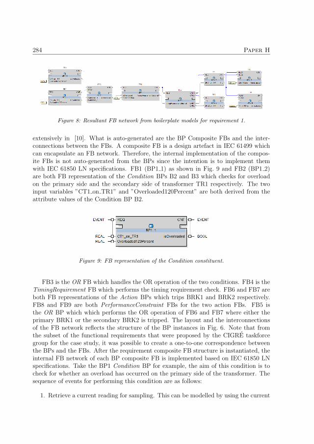
284 Paper H
Figure 8: Resultant FB network from boilerplate models for requirement 1.
extensively in [10]. What is auto-generated are the BP Composite FBs and the inter-connections between the FBs. A composite FB is a design artefact in IEC 61499 whichcan encapsulate an FB network. Therefore, the internal implementation of the compos-ite FBs is not auto-generated from the BPs since the intention is to implement themwith IEC 61850 LN specifications. FB1 (BP1 1) as shown in Fig. 9 and FB2 (BP1 2)are both FB representation of the Condition BPs B2 and B3 which checks for overloadon the primary side and the secondary side of transformer TR1 respectively. The twoinput variables ”CT1 on TR1” and ”Overloaded120Percent” are both derived from theattribute values of the Condition BP B2.
Figure 9: FB representation of the Condition constituent.
FB3 is the OR FB which handles the OR operation of the two conditions. FB4 is theTimingRequirement FB which performs the timing requirement check. FB6 and FB7 areboth FB representations of the Action BPs which trips BRK1 and BRK2 respectively.FB8 and FB9 are both PerformanceConstraint FBs for the two action FBs. FB5 isthe OR BP which which performs the OR operation of FB6 and FB7 where either theprimary BRK1 or the secondary BRK2 is tripped. The layout and the interconnectionsof the FB network reflects the structure of the BP instances in Fig. 6. Note that fromthe subset of the functional requirements that were proposed by the CIGRE taskforcegroup for the case study, it was possible to create a one-to-one correspondence betweenthe BPs and the FBs. After the requirement composite FB structure is instantiated, theinternal FB network of each BP composite FB is implemented based on IEC 61850 LNspecifications. Take the BP1 Condition BP for example, the aim of this condition is tocheck for whether an overload has occurred on the primary side of the transformer. Thesequence of events for performing this condition are as follows:
1. Retrieve a current reading for sampling. This can be modelled by using the current

5. Conclusion and Future Work 285
transformer LN TCTR;
2. Compare the current reading to see whether an overload has occurred. This can bemodelled by using the overcurrent protection LN PIOC.
The internal IEC 61850 implementation of the composite FB2 in Fig. 8 is shown inFig. 10. Each LN is represented by an FB based on the iLN architecture [4]. The iTCTRFB obtains a sample reading of the current and passes this sample to the iPIOC FB foroverload check. If the reading is overloaded, then the iPIOC FB outputs a TRUE valuein the Op general output which is linked to the isOverloaded data output in FB2. Basedon the MDE framework presented in Fig. 2, the internal IEC 61850 LN implementationcan also be auto-generated since an IEC 61850 specification ontology is also used as partof the framework.
Figure 10: Internal FB implementation of the Condition Composite FB
.
5 Conclusion and Future Work
A requirement modelling framework which utilizes semi-formal and formal models ofNL based functional requirements is proposed in this paper which can be applied forautomatically translating functional requirements to IEC 61499 control systems. Thesemi-formal model is based on the use of RNL BPs which add structure and decomposesrequirements to constituent parts. The BP model is then translated to a formal model inontology where the relationships and the attribute values of the BPs are formalized. Theproposed modelling approach is then demonstrated on a CIGRE case study model illus-trating how NL based functional requirements can be translated to the end automationcontrol using various semi-formal and formal models through the design chain. The ben-efits of the proposed modelling framework are threefold. Firstly, sub-sets of semi-formalmodels of functional requirements in BPs are defined to ascertain functional structuresthat are represented by each BP model. Secondly, a formal ontological model of func-tional requirements can reduce the ambiguities in NL requirements and in addition, it ismachine interpretable. Lastly, incorporating requirements in the smart grid MDE frame-work in Fig. 2 addresses one of the major limitation of existing IEC 61850/IEC 61499

286 Paper H
based MDE work which can only auto-generate the structure of the IEC 61499 controlsystem and not the control flow between the FBs. The functional requirements define theinteractions between the LN specifications and therefore, control flow in the IEC 61499control system can be auto-generated from the formal ontological model of the functionalrequirements as showed in this paper.
The future work pertains to several limitations which need to be addressed in thiswork. Firstly, the translating of the NL representation to the BP representation is cur-rently done manually instead of automatically generated. However, as shown by existingresearch works, domain ontologies can be used to aid the automatic generation of BPsfrom NL requirements. Secondly, since the IEC 61850 LN implementation resides withineach BP FB, this limits the reuse of IEC 61850 LNs if several requirements require the useof the same LN. This limitation is addressable by exploring the use of alternative designpatterns such as the SOA based design pattern [38] which decouples the requirementsfrom the implementation of the specification. Lastly, testing and validating the correct-ness of the end IEC 61499 automation control system against the functional requirementis essential. Requirement testing and tracing techniques such as the TORUS frameworkby Sinha et al. in [39] can be incorporated into the framework.
References
[1] H. Gharavi, H. Chen, and C. Wietfeld, “Guest editorial special section on cyber-physical systems and security for smart grid,” IEEE Transactions on Smart Grid,vol. 6, no. 5, pp. 2405–2408, September 2015.
[2] NIST, “Nist framework and roadmap for smart grid interoperability standards, re-lease 3.0,” 2014. [Online]. Available: http://www.nist.gov/smartgrid/upload/NIST-SP-1108r3.pdf
[3] N. Higgins, V. Vyatkin, N. K. C. Nair, and K. Schwarz, “Distributed power systemautomation with iec 61850, iec 61499, and intelligent control,” IEEE Transactionson Systems, Man, and Cybernetics, Part C (Applications and Reviews), vol. 41,no. 1, pp. 81–92, Jan 2011.
[4] G. Zhabelova and V. Vyatkin, “Multiagent smart grid automation architecture basedon iec 61850/61499 intelligent logical nodes,” IEEE Transactions on Industrial Elec-tronics, vol. 59, no. 5, pp. 2351–2362, May 2012.
[5] T. Strasser, M. Stifter, F. Andren, D. B. de Castro, and W. Hribernik, “Applyingopen standards and open source software for smart grid applications: Simulation ofdistributed intelligent control of power systems,” in 2011 IEEE Power and EnergySociety General Meeting, July 2011, pp. 1–8.
[6] W. W. Royce, “Managing the development of large software systems: concepts andtechniques,” in Proceedings of the 9th international conference on Software Engi-neering. IEEE Computer Society Press, 1987, pp. 328–338.

References 287
[7] I. Sommerville and P. Sawyer, Requirements engineering: a good practice guide.John Wiley & Sons, Inc., 1997.
[8] B. W. Boehm, “Software engineering economics,” IEEE Transactions on SoftwareEngineering, vol. SE-10, no. 1, pp. 4–21, Jan 1984.
[9] J. M. Stecklein, J. Dabney, B. Dick, B. Haskins, R. Lovell, and G. Moroney, “Errorcost escalation through the project life cycle,” 2004.
[10] C.-W. Yang, V. Dubinin, and V. Vyatkin, “Ontology driven approach to generatedistributed automation control from substation automation design,” IEEE Trans-actions on Industrial Informatics, vol. 13, no. 2, pp. 668–679, April 2017.
[11] R. Santodomingo, S. Rohjans, M. Uslar, J. A. RodrAguez-MondA¨jar, and M. A.Sanz-Bobi, “Facilitating the automatic mapping of iec 61850 signals and cim mea-surements,” IEEE Transactions on Power Systems, vol. 28, no. 4, pp. 4348–4355,Nov 2013.
[12] R. Santodomingo, J. A. Rodriguez-Mondejar, and M. A. Sanz-Bobi, “Using semanticweb resources to translate existing files between cim and iec 61850,” IEEE Trans-actions on Power Systems, vol. 27, no. 4, pp. 2047–2054, Nov 2012.
[13] W. Dai, V. N. Dubinin, and V. Vyatkin, “Migration from plc to iec 61499 usingsemantic web technologies,” IEEE Transactions on Systems, Man, and Cybernetics:Systems, vol. 44, no. 3, pp. 277–291, March 2014.
[14] ——, “Automatically generated layered ontological models for semantic analysis ofcomponent-based control systems,” IEEE Transactions on Industrial Informatics,vol. 9, no. 4, pp. 2124–2136, Nov 2013.
[15] W. Dai, V. N. Dubinin, J. H. Christensen, V. Vyatkin, and X. Guan, “Towardself-manageable and adaptive industrial cyber-physical systems with knowledge-driven autonomic service management,” IEEE Transactions on Industrial Infor-matics, vol. 13, no. 2, pp. 725–736, April 2017.
[16] W. Lepuschitz, A. Zoitl, M. Vallee, and M. Merdan, “Toward self-reconfiguration ofmanufacturing systems using automation agents,” IEEE Transactions on Systems,Man, and Cybernetics, Part C (Applications and Reviews), vol. 41, no. 1, pp. 52–69,Jan 2011.
[17] S. Sendall and W. Kozaczynski, “Model transformation: the heart and soul of model-driven software development,” IEEE Software, vol. 20, no. 5, pp. 42–45, Sept 2003.
[18] S. Blair, F. Coffele, C. Booth, and G. Burt, “An open platform for rapid-prototypingprotection and control schemes with iec 61850,” in 2013 IEEE Power Energy SocietyGeneral Meeting, July 2013, pp. 1–1.

288 Paper H
[19] R. Paulo and A. Carvalho, “Towards model-driven design of substation automa-tion systems,” in CIRED 2005 - 18th International Conference and Exhibition onElectricity Distribution, June 2005, pp. 1–5.
[20] F. Andren, M. Stifter, and T. Strasser, “Towards a semantic driven frameworkfor smart grid applications: Model-driven development using cim, iec 61850 andiec 61499,” Informatik-Spektrum, vol. 36, no. 1, pp. 58–68, Feb 2013. [Online].Available: http://dx.doi.org/10.1007/s00287-012-0663-y
[21] F. P. Andren, T. Strasser, and W. Kastner, “Applying the sgam methodology forrapid prototyping of smart grid applications,” in IECON 2016 - 42nd Annual Con-ference of the IEEE Industrial Electronics Society, Oct 2016, pp. 3812–3818.
[22] F. Andren, T. Strasser, and W. Kastner, “Model-driven engineering applied to smartgrid automation using iec 61850 and iec 61499,” in 2014 Power Systems ComputationConference, Aug 2014, pp. 1–7.
[23] A. Mercurio, A. D. Giorgio, and P. Cioci, “Open-source implementation of moni-toring and controlling services for ems/scada systems by means of web services -iec 61850 and iec 61970 standards,” IEEE Transactions on Power Delivery, vol. 24,no. 3, pp. 1148–1153, July 2009.
[24] J. P. Barros, I. S. Brito, and L. Gomes, “Requirements specification for controllerdesign - from use cases to iopt net models,” in 2014 12th IEEE International Con-ference on Industrial Informatics (INDIN), July 2014, pp. 207–212.
[25] S. S. Some, “Formalization of textual use cases based on petri nets,” InternationalJournal of Software Engineering and Knowledge Engineering, vol. 20, no. 05, pp.695–737, 2010.
[26] E. Sarmiento, J. C. Leite, E. Almentero, and G. S. Alzamora, “Test scenario gen-eration from natural language requirements descriptions based on petri-nets,” Elec-tronic Notes in Theoretical Computer Science, vol. 329, pp. 123–148, 2016.
[27] R. Sinha, S. Patil, C. Pang, V. Vyatkin, and B. Dowdeswell, “Requirements engi-neering of industrial automation systems: Adapting the cesar requirements metamodel for safety-critical smart grid software,” in IECON 2015 - 41st Annual Con-ference of the IEEE Industrial Electronics Society, Nov 2015, pp. 002 172–002 177.
[28] B. Dowdeswell, R. Sinha, and E. Haemmerle, “Torus: Tracing complex require-ments for large cyber-physical systems,” in 2016 21st International Conference onEngineering of Complex Computer Systems (ICECCS), Nov 2016, pp. 23–32.
[29] B. Khurshid, M. Moshirpour, A. Eberlein, and B. H. Far, “An automated ontologygeneration technique for an emergent behavior detection system,” in 2013 IEEE14th International Conference on Information Reuse Integration (IRI), Aug 2013,pp. 380–387.

289
[30] Y. Amannejad, M. Moshirpour, B. H. Far, and R. Alhajj, “From requirements tosoftware design: An automated solution for packaging software classes,” in Proceed-ings of the 2014 IEEE 15th International Conference on Information Reuse andIntegration (IEEE IRI 2014), Aug 2014, pp. 36–43.
[31] R. Sinha, C. Pang, G. S. Martınez, and V. Vyatkin, “Automatic test case generationfrom requirements for industrial cyber-physical systems,” Automatisierungstechnik,vol. 64, pp. 216–230, 2016.
[32] M. Ortel, M. Malot, A. Baumgart, J. S. Becker, R. Bogusch, S. Farfeleder, N. Gerber,O. Haugen, S. Hausler, B. Josko et al., “Requirements engineering,” in CESAR-Cost-efficient Methods and Processes for Safety-relevant Embedded Systems. Springer,2013, pp. 69–143.
[33] S. Farfeleder, T. Moser, A. Krall, T. Stalhane, H. Zojer, and C. Panis, “Dodt: In-creasing requirements formalism using domain ontologies for improved embeddedsystems development,” in 14th IEEE International Symposium on Design and Di-agnostics of Electronic Circuits and Systems, April 2011, pp. 271–274.
[34] A. Mavin, P. Wilkinson, A. Harwood, and M. Novak, “Easy approach to require-ments syntax (ears),” in 2009 17th IEEE International Requirements EngineeringConference, Aug 2009, pp. 317–322.
[35] T. R. Gruber, “A translation approach to portable ontology specifications,” Knowl-edge acquisition, vol. 5, no. 2, pp. 199–220, 1993.
[36] W. N. Borst and W. Borst, “Construction of engineering ontologies for knowledgesharing and reuse,” 1997.
[37] J. Davies, R. Studer, and P. Warren, Semantic Web technologies: trends and researchin ontology-based systems. John Wiley & Sons, 2006.
[38] C.-W. Yang, V. Vyatkin, and C. Pang, “Service-oriented extension of iec 61850for model-driven smart grid automation design,” in Industrial Electronics Society,IECON 2017-43rd Annual Conference of the IEEE. IEEE, 2017, pp. 5489–5496.
[39] R. Sinha, B. Dowdeswell, G. Zhabelova, and V. Vyatkin, “Requirements Traceabilityfor Dependable CPS using TORUS,” ACM Transactions on Cyber-Physical Systems,vol. 1, no. 1, 2011.

290

Paper I
Automated Fault Location andIsolation in Distribution Grids withDistributed Control and Unreliable
Communication
Authors:Neelabh Kashyap, Chen-Wei Yang, Paul Flikkema and Seppo Sierla
Reformatted version of paper originally published in:2015 IEEE Transactions on Industrial Electronics
c© 2017, IEEE, Reprinted with permission.
291

292

Automated Fault Location and Isolation in
Distribution Grids with Distributed Control and
Unreliable Communication
Neelabh Kashyap, Chen-Wei Yang, Paul Flikkema and Seppo Sierla
Abstract
This paper presents the analysis and simulation of the performance of fault location andisolation (FLI) in an automated power distribution feeder. This system is composed oftwo coupled networks: a power system consisting of a distribution feeder with multipleload buses, and an unreliable communication network of the distributed intelligent agentsin the system, namely, the substation automation and fault protection units separatingsegments of the feeder. We provide a complete specification of a distributed algorithmfor FLI and an exact characterization of the time from the occurrence of a fault to itslocation and isolation. Both apply to a distribution feeder with an arbitrary numberof buses. These models are then refined into a hybrid simulation that combines threemodels executing in parallel: a power system model based on dc power flow, a distributedautomation system model for the intelligent agents constructed using the IEC 61499distributed automation standard, and an abstract communication network model thatunreliably links the physically distributed agents. The results demonstrate the effect ofcommunication network reliability at two levels of design abstraction, the correspondenceof results at the two levels, and the use of a modern cosimulation framework to verifythe performance of the distributed smart grid automation algorithms.
1 Introduction
The principle of self-healing is central to the idea of a Smart Grid. Self-healing, amongother functionalities, consists of the grid’s ability to locate a fault, report the problemto a control center, and then restore the supply of electricity to a majority of affectedcustomers, all without human intervention [1].
Within the context of a distribution system, the self-healing functionality is known asautomated fault location, isolation, and service restoration (FLISR) [2]. In many existingsystems, however, the FLISR procedure is not fully automated[3]. In fully-automatedFLISR, faults are sensed, the fault section is identified and isolated, and power supplyis restored to customers by automatically switching them to a non-faulted section of thesystem. This is achieved by endowing circuit breakers, relays and switches with suffi-cient computational power to behave as intelligent agents [4] which exchange informationamongst themselves through a communication network to accomplish a control task.
293

294 Paper I
1.1 Previous and Related Work
The cosimulation of the power system and communication network in smart grid systemshas received increasing attention in the research community. Lin et al. [5] presenta review of work in the area and describe an event-driven cosimulation approach tointegrate and synchronize a commercial power system simulator (GE PSLF) and anopen-source communication network simulator (ns-2). Earlier work [6] used ns-2 with ageneral-purpose discrete-event simulation tool. Recent results in real-time simulation arepresented in [7].
In the industrial informatics community, the combination of the IEC 61499 distributedfunction block architecture and the IEC 61850 standard for substation automation hasemerged as an architectural platform for several applications in decentralized and mul-tiagent smart grid automation [8]. One reason for adopting these technologies is theincreased requirements for interoperability [9, 10, 11] and reconfigurability [12] in thesmart grid. Some authors have developed decentralized [13] or multiagent-based [14]protection schemes on this technological platform. For example, distributed algorithmsfor location/ isolation and system restoration based on the IEC 61850 GOOSE messagingstandard are proposed in [15].
The decentralized IEC 61499-based automation approach described in this paper aimsto ease the integration of automation into real-world electric grids by supporting the IEC61850 standard now established in industry; this integration is described in [3] and [10],and our paper is a direct extension to this work. IEC 61499 is not currently used incommercial electric grid automation applications, but its use is motivated in this paper bythe anticipated need for greater capabilities in distributed and intelligent automation andmore advanced software engineering methodologies for emerging industrial automationapplications, including a more decentralized smart grid [16, 17].
According to Zhabelova and Vyatkin [3], a major motivation to replace the currentcentralized grid protection technology with decentralized multi-agent based technologyis the improvement in response times, but there is a lack of research to quantify theseexpected improvements. Another limitation in research to date in multi-agent smart gridfault isolation, location and supply restoration is that the communication losses are notconsidered; for example the algorithms in [3] are not intended to cope with a single lostpacket. Due to reasons of cost, wireless technologies are a very attractive yet unreliableoption; the requirements of wireless networking technologies for smart grid applicationsare analyzed in [18] and [19], and experimental data are presented in [20]. The integrationof wireless sensor networking and standards-based automation is considered in [21], whichsketches the algorithms but does not provide any experimental results. Thus one objectiveof this paper is to reconsider the algorithms in [3] and redefine them to cope with anunreliable communication network.
Several multi-agent approaches have been proposed for smart grid automation [22, 23]and power system restoration [24, 25, 26]. A multi-agent appropach to the fault location,isolation, and service restoration (FLISR) problem can be found in [27]. However, theeffects of a realistic communication network linking the distributed intelligent agents hasnot been investigated. Furthermore, most of the research on smart grid automation with

1. Introduction 295
IEC 61499/61850 relies on a co-simulation environment that integrates the automationwith a simulation of the physical grid [28, 29]. In this paper, we augment the co-simulationenvironment with a model of the communication network losses, so that statisticallymeaningful performance results may be obtained. A similar approach for the control ofislanded microgrids has been proposed in [30].
1.2 Contributions
This work builds on the approach of Higgins et al. [10] and Zhabelova and Vyatkin[3], which describe the flow from model-based design to simulation using IEC 61850 and61499 standards. In particular, they demonstrate the feasibility of co-simulating a powerdistribution system using Matlab/Simulink and IEC 61499 automation environments.They also illustrate the capability of standards-based automation to perform automatedFLISR.
In this paper, we present a layered modeling approach that supports the analysisof the performance of fault location and isolation (FLI) for primary power distributionfeeders using wireless networked sensing and control. Our specific objective is to analyzethe effect of the reliability of the communication network on the time required for theoverall system to locate and isolate the fault and inform the substation of the faultlocation. These tasks must be completed prior to initiation of restoration of service.
The scope of the simulation case studies (see Section V) is similar to work publishedin [8], and this research builds directly on those results. The main motivation in [8]for introducing distributed automation in smart grid FLISR is to address the followingproblem: “The main drawback of the central control FLISR solution is insufficient re-sponse time due to the geographical distribution of the primary equipment across thedeployment areas” [8, p. 2353]. This previous work demonstrates the functionality ofthe distributed automation software, but assumes instantaneous and perfectly reliablecommunication. In this paper, we describe analytical and simulation-based methodolo-gies that can be used to obtain full statistical distributions of the fault location/isolationperformance. These are distributions of the total time required to do the following: (1)locate and isolate the fault and (2) inform the substation automation system of the faultlocation, as a function of communication network delay, packet loss probability and thenumber of segments in a distribution feeder. Because the effects of communication areprobabilistic, the simulation framework automatically executes and records results froma statistically significant number of simulation runs
We first present a general algorithm for FLI in a distribution feeder with an arbitrarynumber of load buses. Then we construct a model for analysis that leads to closed-formresults completely describing the time required for location and isolation under unreli-able communication using the general algorithm. Then we describe a team-of-simulatorsapproach to modeling the physical, control, and communication subsystems of the auto-mated distribution feeder. Our results show that the analytical model corroborates thesimulation results.

296 Paper I
2 Electrical System and Protection
We consider automated FLI in the context of a radially connected distribution system.In particular, we focus on a single distribution feeder of the type shown in Fig. 1 [31].As shown in Fig. 1, each feeder segment separates two load buses, which may, in turn,be entire secondary distribution systems or laterals, depending on whether the feederbelongs to a primary or secondary distribution system.
Transformer ControlLine Load
CircuitBreakerFPA_1 FPA_2 FPA_N
SSP
IsolatorSwitch
Figure 1: Single-line diagram of a single feeder distribution system showing protection equip-ment.
Protective relays are equipment which detect abnormal power conditions and initi-ate corrective action as quickly as possible in order to return the power system to itsnormal state. The terms ”protective relays” and ”protection” shall hereafter be usedinterchangeably. In this paper, we assume that the transformer protection and loadprotection are self-contained and do not overlap with the feeder protection. The feederprotection consists of a protection system on the substation side of the feeder, as well asone at every bus connected to the distribution side.
In the following, we describe the different feeder protection systems that behave asintelligent agents and collaborate to achieve FLI in a distributed manner. We also mapsome of the functionalities of these agents to IEC 61850 logical nodes.
2.1 Substation-Side Protection (SSP)
At the substation, the feeder protection system consists of an instantaneous overcurrentrelay (PIOC) which trips (opens) a circuit breaker (XCBR) on all three phases when afault current persists for a predetermined number of cycles. The overcurrent relay relieson measurements from a current transformer (TCTR) on all three phases. To handletransients or false alarms, a reclosing relay (RREC) attempts to automatically close thecircuit breaker after a set delay. If the fault is still detected, the overcurrent relay tripsthe circuit breaker again. After reclosing is attempted a few times, the reclosing relaygoes into ”lockout” (a permanent open until service restoration), and a message is sentto the substation automation computer reporting a fault.

3. Fault Location and Isolation 297
2.2 Feeder Protection Unit (FP)
The protection system for the feeder on the load buses consists of an overcurrent relay(PIOC) which trips a circuit breaker (XCBR) on all three phases when a fault currentpersists for a set number of cycles. As with the substation-side protection (SSP), theovercurrent relay operates based on measurements from a current transformer (TCTR) onall three phases. Additionally, we assume that the circuit breaker in the feeder protectionsystem can also be tripped by providing an external control signal (CSWI).
The feeder protection unit (FP) also includes an isolator switch (CSWI and XCBR)which isolates the feeder section downstream of the bus from the feeder section upstreamof it. This switch can be remotely triggered via a control signal. The isolator switch isrequired to fully disconnect both ends of the faulted feeder segment. Otherwise, whenservice is restored, one end of the faulted section would be live.
The SSP and FPs are also equipped with communication transceivers to exchangemessages over a wireless network. These messages can be based on the IEC 61850 GOOSEmessaging standard, and are transmitted from the sender to the receiver using multiplehops. In the following section, we describe the messaging protocol between the SSP andthe FPs which achieves the location and isolation of a fault.
3 Fault Location and Isolation
The objective of the FLI step is to identify the faulted feeder section and isolate thissection before the service restoration protocol begins.
3.1 Feeder model
Consider an N -bus feeder as shown in Fig. 1. The substation protection system isdenoted by SSP and the feeder protection system associated with the ith bus is denotedby FPi, where i = 1, . . . , N .
The overcurrent relay in the SSP trips the circuit breaker if the current flowing throughthe feeder exceeds a threshold current for a time tS. Note that, in current practice, theovercurrent protection relays in feeder protection systems FP1 through FPN are config-ured to trip if the current exceeds a threshold for a time duration t1, . . . , tN respectively,where
tS < tN < tN−1 < · · · < t1,
so that the SSP circuit breaker trips before any of the overcurrent relays in the FPsystems. This is vital to the successful execution of the protocol described in this paper.It is assumed that the overcurrent relays in the feeder protection system are set to operatebefore overcurrent current relays associated with load protection.
We denote the state of feeder protection system FPi by xi ∈ {0, 1}. The state variablexi is set to 1 if FPi senses a fault current, and xi = 0 otherwise. Therefore, if xM−1 = 1and xM = 0, for any M ∈ {1, . . . , N}, there is a fault in the feeder segment betweenbuses M − 1 and M .

298 Paper I
The location and isolation of the faulted feeder segment entails exchanging a seriesof messages in a structured manner, such that the (i) the faulted segment is locatedand isolated, and (ii) the substation automation system becomes aware of the faultedsegment. This exchange of messages is initiated when substation automation system isinformed that the recloser is in lockout, and it is described in what follows.
3.2 Fault Location and Isolation Algorithm
Our algorithm is designed to locate and isolate any fault detected by the SSP and FPhardware. The algorithm uses three messages, namely LOCKOUT, FAULT and LOCATED. TheLOCKOUT message informs an FP that the substation side recloser is in lockout. Whena fault occurs, the SSP associated with the faulted feeder sends a LOCKOUT message toboth the substation automation computer as well as the FP immediately downstream ofit. If an FP receives a LOCKOUT message, and it has registered a fault current, then theLOCKOUT message is forwarded to the next FP immediately downstream. If a LOCKOUT
message is received and a fault current is not registered then the conclusion is that faultis located upstream of the FP. If a FAULT message is received by FPi, then FPi becomesaware that the faulted segment is the one between buses i and i+ 1. Then, FPi creates aLOCATED message which contains information to the effect that the fault has been locatedand it lies in the segment between buses i and i + 1. This message is then propagatedin the direction of the substation, i.e, FPi sends the message to FPi−1, FPi−1 sends it toFPi−2, and so on until it reaches the substation automation computer. The manner inwhich each FP processes the three messages described above is shown in Algorithm 1.
if LOCKOUT is received thenif xi = 1 then
Send LOCKOUT to FPi+1;else
Send FAULT to FPi−1;Open isolator switch;
end
endif FAULT is received then
Open circuit breaker;Create LOCATED;Send LOCATED to FPi−1;
endif LOCATED is received then
Send LOCATED to FPi−1;end
Algorithm 1: FLI protocol handling in FPi in a wireless networked control archi-tecture.

4. Analysis of the FLI Algorithm 299
3.3 Communication Network
Consider a distribution feeder consisting of N feeder segments each with an associatedFP. The messages defined in Section 3.2, e.g., LOCKOUT, are encoded into packets fortransmission. The reliability of the communication link (i, j) from node i to its neighborsj ∈ {i± 1} is modeled by a probability of packet error φj
i (t), which can be easily relatedto the link’s raw bit error probability and any forward error-control coding used at thelink level. Packet transmissions are not assumed successful until an acknowledgementpacket is received by the sender, so that a complete transaction requires two successfultransmission-receptions. When node i transmits a packet to node j, this transaction isnot successful with probability ρij(t) = 1 − (1 − φj
i (t))(1 − φij(t)); hence ρij(t) is the
probability of failure for the transaction between nodes i and j at time t.
In this abstract model, the FP’s and SSP can communicate using any network archi-tecture; depending on the architecture, the links may be physical or logical. For example,in a meshed network, the SSP and all FP’s can communicate with neighboring units atthe physical layer. The network may also form a logical star supported, e.g., by cellularinfrastructure, using wireless communication with base stations and, if necessary, thewired backhaul network.
4 Analysis of the FLI Algorithm
In this section we develop a probabilistic model for the number of message transactionsT from the occurrence of a fault (and the associated tripping and lockout at the SSP) toisolation of the fault and knowledge of its location at the SSP, which we refer to as thelocation/isolation time. We characterize this time as a function of the performance (interms of communication reliability) of the wireless communication network connectingthe FPs. While it is tempting to seek summary measures for T such as its mean E(T ),it is more meaningful to determine the probability that T is less than some value t,for example, the 95% localization/isolation time, requiring the complete characterization(probability distribution) of T .
Assume that the fault is located between FPM−1 and FPM . Then location and isola-tion of the fault requires 2M successful transactions, one each on the ordered set of di-rected links {(0, 1), (1, 2), . . . (M−1,M), (M,M−1), . . . (1, 0)}. Note that isolation occursupon success of the transactions on the link set {(0, 1), (1, 2), . . . (M−1,M), (M,M−1)},requiring M + 1 successful transactions, but knowledge of the location (and isolation) ofthe fault at the substation requires 2M transactions.
In this application, the transaction failure probabilities can be assumed independent.Under this condition, the location/isolation process can be modeled in its full generalityas a time-variant birth process or equivalently as a non-homogeneous Markov chain;details are beyond the scope of this paper.
However, we can obtain the general behavior of the location/isolation process if weassume that there is no spatio-temporal variation in the probability of transaction failure(i.e., all links are identical and no fading occurs), then ρij(t) = ρ ∀i, j, t. Since faults closer

300 Paper I
to the substation require fewer transactions, it is appropriate to model T as conditionalon the fault location M , allowing an arbitrary distribution for the fault location. Sincelocation/isolation occurs after 2M successful transactions, the total number of (unsuc-cessful and successful) transactions, and hence the number of time steps to completion,can be modeled as Bernoulli trials with success probability 1 − ρ. Thus the probabilitydistribution of T given M = m is negative binomial with parameters t and 2m:
p[T = t|M = m] =
(t− 1
2m− 1
)(1− ρ)2mρt−2m. (1)
Note that T ≥ 2m, viz., the time to completion can be no less than 2m, even withperfectly reliable communication. In our simulation results, we use specific values of M ;hence the results are in reported in the form of (1).
Fig. 2 shows the probability mass function of T when M = 3, i.e., p(T = t|M = 3)for different values of ρ. Here, t is the number of message transaction time slots. We see,as expected, that the probability that it takes t communications time-slots to completeFLI decreases as the reliability of the communications channel increases (ρ decreases).
6 7 8 9 1010
−6
10−5
10−4
10−3
10−2
10−1
100
xlabel
ylab
el
ρ = 0.01ρ = 0.025ρ = 0.05ρ = 0.075ρ = 0.1
Figure 2: Performance of of the proposed location/isolation algorithm as function of packet lossprobability ρ. The fault is located between FP2 and FP3, i.e., (M = 3).
In general, the worst-case distribution for T occurs when M = N . For any probabilitymass function p[M = m] modeling the probability of a fault occurring in the feeder section

4. Analysis of the FLI Algorithm 301
between Buses m− 1 and m, the distribution of T is found via marginalization, i.e.,
p[T = t] =N∑
m=1
p[T = t|M = m]p[M = m]. (2)
A more intuitive way to understand (2) is by plotting the cumulative distributionfunction (CDF) of T , p(T ≤ t), which is the probability that it takes no more than ttime slots to locate and isolate the fault. The CDF is given by
p(T ≤ t) =t∑
i=1
N∑m=1
p[T = i|M = m]p[M = m], (3)
and hence, p(T ≤ t)→ 1 as t increases.Plotting (3) for various practical values of ρ shows that convergence is quite rapid, as
evidenced by Fig. 3 and Fig. 4.
0 5 10 15 20 25
10−1
100
xlabel
ylab
el
M = 2M = 4M = 6M = 8M = 10
Figure 3: Performance of of the proposed proposed FLI algorithm for M feeder segments whenp[M = m] follows a uniform distribution, and ρ = 0.01. The performance curves are generatedusing (2).
In summary, we derive a probabilistic expression for the number of message trans-actions required to locate and isolate a fault on a single distribution feeder. Since a

302 Paper I
0 5 10 15 20 25
10−1
100
xlabel
ylab
el
M = 2M = 4M = 6M = 8M = 10
Figure 4: Performance of of the proposed proposed FLI algorithm for M feeder segments whenp[M = m] follows a uniform distribution, and ρ = 0.05. The performance curves are generatedusing (2).
feeder always runs from a substation to the loads, extension of the current algorithmto larger systems would simply involve communication between the SSPs and a maincontrol center to determine the location of the fault in the larger system, irrespective ofits topology.
5 Simulation
In this section we describe the simulation setup used to verify the FLI algorithm pre-sented in Section 3. Our simulation model consists of three simulators executing intwo simulation environments, namely, Simulink and nxtStudio. Using the paradigm ofcyber-physical systems (CPS), the physical subsystem is modeled using the Simulinkenvironment, and itself consists of two models, one for the power distribution grid, andone for the model of the unreliable communication network. The cyber subsystem ismodeled using nxtStudio, a simulation environment compliant with the IEC 61499 dis-tributed automation standard. These subsystems interact with each other as shown inFig. 5.
We first describe the physical power system model implemented in Simulink. Wethen describe how the communications network model is simulated. We go on to outline

5. Simulation 303
61499
Simulink
UDP UDP
UDP UDP
ControlModel
PowerSystemModel NetworkModel
Figure 5: Co-simulation architecture for FLI in an automated distribution feeder, reflectingheterogeneity of control, power system, and communication network modeling semantics. Modelsare implemented in two simulation environments.
the implementation of the control system in nxtStudio using IEC 61499 function blocks.Finally, we describe how the three disparate simulators are integrated in order to form asingle co-simulation environment.
As shown in Fig. 6, the power system simulated is a three-phase 11 kV 60 Hzdistribution system with a single feeder. The distribution substation contains a step-down transformer, the secondary of which is connected to the distribution feeder. Thefeeder is connected to three loads through buses.
5.1 Power System Model
FPA_1 FPA_2 FPA_3
SSP
L1 L2 L3
F1 F2
Figure 6: Single-line diagram of the simulated single feeder distribution system. f1 and f2indicate the locations of the faults that are simulated in Section 6.
This system is modeled in Simulink using the SimPowerSystems blockset. The pri-mary of the wye-connected transformer at the distribution substation is connected to a33 kV transmission line. This is modeled by connecting the Three-Phase Source block

304 Paper I
0 0.05 0.1 0.15 0.2 0.25 0.3 0.35 0.4 0.45 0.5−1
0
1
2
3x 10
4
xlabel
ylab
el(a)
0 0.05 0.1 0.15 0.2 0.25 0.3 0.35 0.4 0.45 0.5−100
−50
0
50
100
xlabel
ylab
el
(b)
Figure 7: Current waveforms of the A-phase at the substation (a) and Load L1 (b). Power isshut off to the load when a fault is detected.
in Simulink to the primary side of the Three-Phase Transformer block. The loads aremodeled using the Three-Phase Series RLC Load block with a real power demand of 10kW and a reactive power demand of 100 VAR. The load remains constant throughoutthe simulation.
Fig. 7 shows the current waveforms of the A-phase obtained by simulating the powersystem with a fault triggered at t = 0.25s.
The Powergui block is used to solve a AC load flow to calculate the node voltages andbranch currents at fixed time steps, chosen in this case to be 1 ms. The fault used in thissimulation is a three-phase-to-ground fault, where a short circuit occurs between all threelines and ground. This is modeled by using the Thee-Phase Fault block in Simulink.
The SSP consists of an overcurrent relay which trips the substation-side circuit breakerif the current exceeds 1 kA. The model of the overcurrent relay in Simulink consists ofa system of blocks connected such that if the output of a Current Measurement blockexceeds 1 kA, a signal is sent to the Three-Phase Breaker block to open the circuitbreaker. The same signal is also sent to nxtStudio using the messaging architecturedescribed in Section 3.2 as the LOCKOUT signal.
The modeling of the overcurrent relay in the FPs is similar to that of the SSP. How-ever, in the case of the FP, the output line of the current measurement block in Simulink,instead of being connected to a circuit breaker, is connected to a level detection block

5. Simulation 305
with outputs 1 if a fault current was detected, and is 0 otherwise. This signal constitutesthe state of the FP and it is sent to nxtStudio as input to the FP control logic.
The circuit breakers and isolator switches, as well as the SSP, are modeled using theThree-Phase Breaker block with the external control line enabled. This is interfacedwith nxtStudio such that the breaker models simulating the circuit breakers and isola-tor switches are controlled by the output signals of the IEC 61499 FP function blocksCB PORT and ISO PORT respectively in Fig. 8.
Figure 8: Implementation of the control architecture in IEC 61499 function blocks.
5.2 Communication Network Model
In our system model, the communication network affects messages that are exchangedbetween the SSP and the FP controllers. The effect of the communication network inthis co-simulation is modeled via interaction between the Simulink and 61499 automa-tion environments. Each SSP and FP unit is modeled as a dedicated controller at itsphysical site; in the 61499 environment, each SSP and FP is implemented as a stand-alone function block. Communication between the two environments is implementedusing User Datagram Protocol (UDP) packet transfers. When a message is transmittedfrom one IEC 61499 function block to another, the sending function block requests thenext (0, 1) outcome of the Bernoulli process from the Simulink model that representsthe communication network. If the value is 1, then the message is transmitted to thereceiving function block. If the value is 0, the message is not sent in the current 61499execution cycle, thus incurring a delay of one time unit. The function block controlleragain requests an outcome from the Bernoulli process; this iteration continues until a 1value is generated, permitting the message to be sent.
The effect of each lost message between function blocks is exhibited as delay of onetime unit in the FLI algorithm. Because of the simplicity of control processing, thisdelay is dominated by communication delays due primarily to the design of media access

306 Paper I
control (MAC) protocols for wireless networking. For example, many of these protocolsdivide time into short (e.g., 10 ms [32]) slots of duration Ts that can be dedicated totransmissions. In this paper we assume that the available network capacity is signifi-cantly larger than the minimum required, so that each transaction requires four suchslots in consecutive order, i.e., one each for transmission of the packet, processing by thereceiver, transmission of the acknowledgement packet, and processing of the acknowl-edgement packet, leading to a delay of 4Ts for a successful transaction, so that the timeto location/isolation is 4Tst. Hence, if a fault occurs between feeder protection systemsFPM−1 and FPM , the minimum time to completion of the FLI algorithm is 8TsM (seeSection 4). The simulation can be easily extended to incorporate more sophisticatedmodels that incorporate correlated fading, or interference from nearby transmitters thatmight prevent the four slots from being consecutive [18].
5.3 Modeling and Implementation of Control
The distributed FLI algorithm is implemented in IEC 61499 function blocks thatcan be developed using several environments and toolchains; here we use the nxtStudioenvironment. In our model (Fig. 8), the two types of protection subsystems described inSection 2 are mapped in one-to-one correspondence to 61499 function blocks. As shown inFig. 8, the SSP controller is implemented as function block SSP of class SSPControlV2.Similarly, the three FP controllers are implemented as three instances, namely FP1, FP2,and FP3, of class FPControlV2, each running Algorithm 1.
5.4 Interfacing Models of Computation
The distributed control system implementation, implemented in the 61499 automationenvironment as function blocks, is triggered by events from the Simulink model of thedistribution feeder system. In the 61499 model, the function block WSNNetwork handlescommunication with the network simulator residing in the Simulink environment. At eachexecution cycle, the SSP controller receives a state value from the power distributionnetwork model. This state values indicates whether the network is in the lockout state,i.e., when a fault is detected and the substation-level circuit breaker is in the openedstate. The FP controllers also receive state values; each FP controller receives a statevalue from the Simulink model indicating whether a fault current was detected in itsprotection zone, defined as the distribution feeder downstream from itself.
The communication interfaces between (i) the power system model and the controllerand (ii) the controller and the communication network model are implemented using UDPcommunication. The Simulink model sends state values to the function block controllerswhile the 61499 function block controllers send actuating control signals to the circuitbreakers and the isolator switches of the Simulink model.
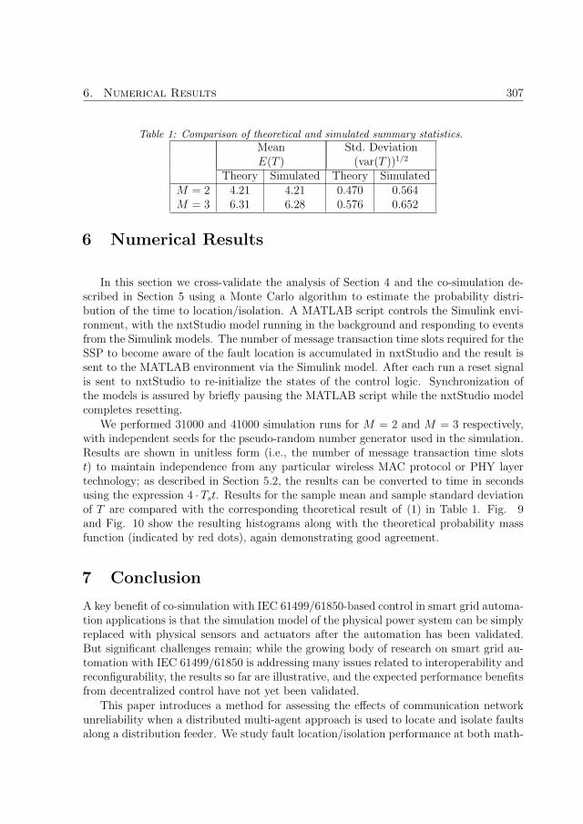
6. Numerical Results 307
Table 1: Comparison of theoretical and simulated summary statistics.Mean Std. DeviationE(T ) (var(T ))1/2
Theory Simulated Theory SimulatedM = 2 4.21 4.21 0.470 0.564M = 3 6.31 6.28 0.576 0.652
6 Numerical Results
In this section we cross-validate the analysis of Section 4 and the co-simulation de-scribed in Section 5 using a Monte Carlo algorithm to estimate the probability distri-bution of the time to location/isolation. A MATLAB script controls the Simulink envi-ronment, with the nxtStudio model running in the background and responding to eventsfrom the Simulink models. The number of message transaction time slots required for theSSP to become aware of the fault location is accumulated in nxtStudio and the result issent to the MATLAB environment via the Simulink model. After each run a reset signalis sent to nxtStudio to re-initialize the states of the control logic. Synchronization ofthe models is assured by briefly pausing the MATLAB script while the nxtStudio modelcompletes resetting.
We performed 31000 and 41000 simulation runs for M = 2 and M = 3 respectively,with independent seeds for the pseudo-random number generator used in the simulation.Results are shown in unitless form (i.e., the number of message transaction time slotst) to maintain independence from any particular wireless MAC protocol or PHY layertechnology; as described in Section 5.2, the results can be converted to time in secondsusing the expression 4 · Tst. Results for the sample mean and sample standard deviationof T are compared with the corresponding theoretical result of (1) in Table 1. Fig. 9and Fig. 10 show the resulting histograms along with the theoretical probability massfunction (indicated by red dots), again demonstrating good agreement.
7 Conclusion
A key benefit of co-simulation with IEC 61499/61850-based control in smart grid automa-tion applications is that the simulation model of the physical power system can be simplyreplaced with physical sensors and actuators after the automation has been validated.But significant challenges remain; while the growing body of research on smart grid au-tomation with IEC 61499/61850 is addressing many issues related to interoperability andreconfigurability, the results so far are illustrative, and the expected performance benefitsfrom decentralized control have not yet been validated.
This paper introduces a method for assessing the effects of communication networkunreliability when a distributed multi-agent approach is used to locate and isolate faultsalong a distribution feeder. We study fault location/isolation performance at both math-

308 Paper I
4 5 6 7 8 90
0.1
0.2
0.3
0.4
0.5
0.6
0.7
0.8
0.9
xlabel
ylab
el
Figure 9: Theoretical and simulated performance of of the proposed FLI algorithm for ρ = 0.05.Fault is located between FP1 and FP2, i.e., M = 2.
6 7 8 9 10 11 12 130
0.1
0.2
0.3
0.4
0.5
0.6
0.7
0.8
0.9
xlabel
ylab
el
Figure 10: Theoretical and simulated performance of of the proposed FLI algorithm for ρ = 0.05.Fault is located between FP2 and FP3, i.e., M = 3.
ematical and simulation-based modelling levels, with closed-form analytical results forthe former. It also demonstrates a principled approach to smart grid automation designthat enables validation of models as they are refined toward deployable hardware.
References
[1] M. Ilic, L. Xie, U. Khan, and J. Moura, “Modeling of future cyber-physical energysystems for distributed sensing and control,” vol. 40, no. 4, pp. 825–838, 2010.
[2] R. Uluski, “Using distribution automation for a self-healing grid,” in Proc. 2012IEEE Transmission and Distribution Conf. and Expo., 2012, pp. 1–5.
[3] G. Zhabelova and V. Vyatkin, “Multiagent smart grid automation architecture basedon IEC 61850/61499 intelligent logical nodes,” vol. 59, no. 5, pp. 2351–2362, 2012.

References 309
[4] B. Russell and C. Benner, “Intelligent systems for improved reliability and failurediagnosis in distribution systems,” vol. 1, no. 1, pp. 48–56, 2010.
[5] H. Lin, S. Veda, S. Shukla, L. Mili, and J. Thorp, “GECO: global event-drivenco-simulation framework for interconnected power system and communication net-work,” vol. 3, no. 3, pp. 1444–1456, 2012.
[6] J. Nutaro, P. Kuruganti, M. Shankar, L. Miller, and S. Mullen, “Integrated modelingof the electric grid, communications, and control,” Intl. Journal of Energy SectorMgmt., vol. 2, no. 3, pp. 420–438, 2008.
[7] F. Guo, L. Herrera, R. Murawski, E. Inoa, C.-L. Wang, P. Beauchamp, E. Ekici, andJ. Wang, “Comprehensive real-time simulation of the smart grid,” vol. 49, no. 2, pp.899–908, 2013.
[8] V. Vyatkin, G. Zhabelova, N. Higgins, M. Ulieru, K. Schwarz, and N. Nair,“Standards-enabled smart grid for the future energy web,” in Proc. 2010 InnovativeSmart Grid Technologies, 2010, pp. 1–9.
[9] C.-W. Yang, J. Yan, and V. Vyatkin, “Towards implementation of plug-and-play anddistributed HMI for the FREEDM system with IEC 61499,” in Proc. 39th AnnualConf. of the IEEE Ind. Electron. Soc., 2013, pp. 5347–5353.
[10] N. Higgins, V. Vyatkin, N. Nair, and K. Schwarz, “Distributed power system au-tomation with IEC 61850, IEC 61499, and intelligent control,” vol. 41, no. 1, pp.81–92, 2011.
[11] T. Strasser, F. Andren, V. Vyatkin, G. Zhabelova, and C.-W. Yang, “Towards anIEC 61499 compliance profile for smart grids review and analysis of possibilities,”in Proc. 38th Annual Conf. on IEEE Ind. Electron. Soc., 2012, pp. 3750–3757.
[12] T. Strasser, F. Andren, F. Lehfuss, M. Stifter, and P. Palensky, “Online reconfig-urable control software for IEDs,” vol. 9, no. 3, pp. 1455–1465, 2013.
[13] C.-W. Yang, G. Zhabelova, V. Vyatkin, N. Nair, and A. Apostolov, “Smart gridautomation: Distributed protection application with IEC61850/IEC61499,” in Proc.10th IEEE Int. Conf. on Ind. Informatics (INDIN), 2012, pp. 1067–1072.
[14] D. Pala, C. Tornelli, and G. Proserpio, “An adaptive, agent-based protection schemefor radial distribution networks based on IEC 61850 and IEC 61499,” in Proc.CIRED Integration of Renewables into the Distribution Grid Workshop, 2012, pp.1–4.
[15] P. Parikh, I. Voloh, and M. Mahony, “Fault location, isolation, and service restora-tion (FLISR) technique using IEC 61850 GOOSE,” in Proc. 2013 IEEE Power andEnergy Soc. General Meeting, 2013, pp. 1–6.

310 Paper I
[16] V. Vyatkin, “IEC 61499 as enabler of distributed and intelligent automation: State-of-the-art review,” vol. 7, no. 4, pp. 768–781, Nov 2011.
[17] ——, “Software engineering in industrial automation: State-of-the-art review,”vol. 9, no. 3, pp. 1234–1249, Aug 2013.
[18] Y. Xu and W. Wang, “Wireless mesh network in smart grid: Modeling and analysisfor time critical communications,” vol. 12, no. 7, pp. 3360–3371, 2013.
[19] M. S. Mahmoud, “Wireless networked control system design: An overview,” in 2014IEEE 23rd International Symposium on Industrial Electronics (ISIE), June 2014,pp. 2335–2340.
[20] V. Gungor, B. Lu, and G. Hancke, “Opportunities and challenges of wireless sensornetworks in smart grid,” vol. 57, no. 10, pp. 3557–3564, 2010.
[21] D. Bin, G. Li, C. Qiu, J. Pan, and Y. Tan, “Fault location and self-healing ofdistribution network based on function block and wireless sensor,” in Proc. IEEEInnovative Smart Grid Technologies, 2012, pp. 1–9.
[22] S. McArthur, E. Davidson, V. Catterson, A. Dimeas, N. Hatziargyriou, F. Ponci,and T. Funabashi, “Multi-agent systems for power engineering applications - Part II:Technologies, standards, and tools for building multi-agent systems,” vol. 22, no. 4,pp. 1753–1759, 2007.
[23] M. Pipattanasomporn, H. Feroze, and S. Rahman, “Multi-agent systems in a dis-tributed smart grid: Design and implementation,” in Proc. 2009 IEEE Power Sys-tems Conf. and Expo., 2009, pp. 1–8.
[24] T. Nagata, Y. Tao, K. Kimura, H. Sasaki, and H. Fujita, “A multi-agent approach todistribution system restoration,” in Proc. 2004 47th Midwest Symposium on Circuitsand Syst., vol. 2, 2004, pp. II–333–II–336.
[25] J. Solanki, S. Khushalani, and N. Schulz, “A multi-agent solution to distributionsystems restoration,” vol. 22, no. 3, pp. 1026–1034, 2007.
[26] S. Chouhan, J. Ghorbani, H. Inan, A. Feliachi, and M. Choudhry, “Smart MASrestoration for distribution system with microgrids,” in Proc. 2013 IEEE Power andEnergy Soc. General Meeting, 2013, pp. 1–5.
[27] A. Zidan and E. El-Saadany, “A cooperative multiagent framework for self-healingmechanisms in distribution systems,” vol. 3, no. 3, pp. 1525–1539, Sept 2012.
[28] C.-H. Yang, G. Zhabelova, C.-W. Yang, and V. Vyatkin, “Cosimulation environmentfor event-driven distributed controls of smart grid,” vol. 9, no. 3, pp. 1423–1435,2013.

References 311
[29] M. Stifter, E. Widl, F. Andren, A. Elsheikh, T. Strasser, and P. Palensky, “Co-simulation of components, controls and power systems based on open source soft-ware,” in Proc. IEEE Power and Energy Soc. General Meeting, 2013, pp. 1–5.
[30] Q. Shafiee, C. Stefanovic, T. Dragicevic, P. Popovski, J. C. Vasquez, and J. M.Guerrero, “Robust networked control scheme for distributed secondary control ofislanded microgrids,” IEEE Transactions on Industrial Electronics, vol. 61, no. 10,pp. 5363–5374, Oct 2014.
[31] W. H. Kersting, Distribution system modeling and analysis. CRC press, 2012.
[32] A. Kim, F. Hekland, S. Petersen, and P. Doyle, “When HART goes wireless: Un-derstanding and implementing the WirelessHART standard,” in Proc. 2008 IEEEInternational Conf. on Emerging Technologies and Factory Automation, 2008, pp.899–907.


![Search-Based Model-Driven Engineering€¦ · Search-Based Model-Driven Engineering ... Model-Driven Engineering (MDE) [31], [9] is a software engineering practice which uses disparate](https://static.fdocuments.in/doc/165x107/5ad3c1867f8b9afa798e673a/search-based-model-driven-engineering-search-based-model-driven-engineering-.jpg)