
CX263 ZONE MIXER - Cloud
22
CX263 Installation and User Guide v1.2 CX263 ZONE MIXER Installation and User Guide
Transcript of CX263 ZONE MIXER - Cloud

CX263 Installation and User Guide v1.2
CX263ZONE MIXER
Installation and User Guide

CX263 Installation and User Guide v1.22
Contents
SAFETY INFORMATION ............................................................................................................. 4Important Safety Instructions ..................................................................................................................................... 4Conformities ................................................................................................................................................................... 4Safety Considerations and Information .................................................................................................................... 5
OVERVIEW ..................................................................................................................................... 6Introduction .................................................................................................................................................................... 6What’s in the box .......................................................................................................................................................... 6Main Features .................................................................................................................................................................. 6
BLOCK DIAGRAM ........................................................................................................................ 7
DESCRIPTION OF FRONT PANEL ............................................................................................ 7
DESCRIPTION OF REAR PANEL ............................................................................................... 8
INSTALLATION ............................................................................................................................. 9Hardware Considerations ........................................................................................................................................... 9Power Supply .................................................................................................................................................................. 9
Fuses and ratings ......................................................................................................................................................... 9System Connections ..................................................................................................................................................... 9
Music Sources .............................................................................................................................................................. 9Microphone inputs ................................................................................................................................................... 10Zone Outputs ........................................................................................................................................................... 10Music Control ........................................................................................................................................................... 10Music Mute ................................................................................................................................................................. 11
SETTING UP & OPERATION .................................................................................................... 12Music Inputs .................................................................................................................................................................. 12
Gain & level ................................................................................................................................................................ 12Local/remote control ............................................................................................................................................... 12Music EQ .................................................................................................................................................................... 12
Microphone Inputs ...................................................................................................................................................... 13Phantom Power ......................................................................................................................................................... 13Gain & level ................................................................................................................................................................ 13Paging Access Control ............................................................................................................................................. 13EQ ................................................................................................................................................................................ 13High-pass filter .......................................................................................................................................................... 13
Zone Outputs ............................................................................................................................................................... 14EQ ................................................................................................................................................................................ 14
Priorities ........................................................................................................................................................................ 14Line 6 priority ............................................................................................................................................................ 14Microphone 1 priority ............................................................................................................................................. 14Mic-over-Music priority ........................................................................................................................................... 14

CX263 Installation and User Guide v1.2 3
OPTIONS AND ADDITIONAL INFORMATION..................................................................... 15CDI-S200 Serial Interface Card ................................................................................................................................ 15RL-1 Series and RSL-6 Series remote control plates – general considerations ............................................15
Control of music source and level via external DC .........................................................................................16 Music level ............................................................................................................................................................... 16 Music source ........................................................................................................................................................... 17
Fitting loudspeaker EQ cards .................................................................................................................................... 17
APPENDIX ................................................................................................................................... 18Application example .................................................................................................................................................... 18PCB jumper location and settings ............................................................................................................................ 19Ground loops ............................................................................................................................................................... 20EMC considerations .................................................................................................................................................... 20Technical Specifications .............................................................................................................................................. 21

CX263 Installation and User Guide v1.24
Safety InformationImportant Safety InstructionsRead these instructions.
• Keep these instructions.• Heed all warnings.• Follow all instructions.• Do not use this apparatus near water.• Clean only with dry cloth.• Do not block any ventilation openings. Install in
accordance with the manufacturer’s instructions.• Do not install near any heat sources such as radiators,
heat registers, stoves, or other apparatus (including amplifiers) that produce heat.
• Do not defeat the safety purpose of the polarized or grounding-type plug. A polarized plug has two blades with one wider than the other. A grounding type plug has two blades and a third grounding prong. The wide blade or the third prong are provided for your safety. If the provided plug does not fit into your outlet, consult an electrician for replacement of the obsolete outlet.
• Protect the power cord from being walked on or pinched particularly at plugs, convenience receptacles, and the point where they exit from the apparatus.
• Only use attachments/accessories specified by the manufacturer.
• Use only with the cart, stand, tripod, bracket, or table specified by the manufacturer, or sold with the apparatus. When a cart is used, use caution when moving the cart/apparatus combination to avoid injury from tip-over.
• Unplug this apparatus during lightning storms or when unused for long periods of time.
• Refer all servicing to qualified service personnel. Servicing is required when the apparatus has been damaged in any way, such as power-supply cord or plug is damaged, liquid has been spilled or objects have fallen into the apparatus, the apparatus has been exposed to rain or moisture, does not operate normally, or has been dropped.
WARNING:
To reduce the risk of fire or electric shock, do not expose this appliance to rain or moisture.
CAUTION:
Use of controls or adjustments or performance of procedures other than those specified may result in hazardous radiation exposure.
CAUTIONRISK OF ELECTRIC SHOCK
DO NOT OPEN
WARNING: SHOCK HAZARD - DO NOT OPEN
AVIS: RISQUE DE CHOQUE ÉLECTRIQUE - NE PAS OUVRIR
The lightning flash with the arrowhead symbol within an equilateral triangle, is intended to alert you to the
presence of uninsulated dangerous voltages within the product’s enclosure that may be of sufficient magnitude to constitute a risk of electric shock.
The exclamation point within an equilateral triangle is intended to alert the user to the presence of important
operating and maintenance (servicing) instructions in the literature accompanying the appliance.
Un point d’exclamation dans un triangle équilatéral est destiné à alerter l’utilisateur de la présence d’instructions importantes sur le fonctionnement et l’entretien (la réparation) dans la documentation accompagnant l’appareil.
The mains plug is used as the disconnect device and it should remain readily accessible during intended use. In
order to electrically isolate the apparatus from the mains, the mains plug should be completely removed from the mains outlet socket.
La prise du secteur ne doit pas être obstruée ou doit être facilement accessible pendant son utilisation. Pour être complètement déconnecté de l’alimentation d’entrée, la prise doit être débranchée du secteur.
Meaning of the label: Evaluation for apparatus only based on temperate climate condition, therefore it’s the only operating condition applied for the
equipment .There may be some potential safety hazard if the equipment is used in tropical climate region.
L’évaluation pour les appareils est basée dans une condition climatique tempérée, donc c’est la seule condition de fonctionnement à appliquer pour l’appareil. Il peut y avoir un risque potentiel pour la sécurité si l’équipement est utilisé dans une région climatique tropical.
Meaning of the label: Evaluation for apparatus only based on altitude not exceeding 2000 m, therefore it’s the only operating condition applied for the
equipment .There may be some potential safety hazard if the equipment is used at altitude above 2000 m.
L’évaluation pour les appareils est basée uniquement sur une altitude inférieure à 2000 m, donc c’est la seule condition de fonctionnement à appliquer pour l’appareil. Il peut y avoir un risque potentiel pour la sécurité si l’équipement est utilisé avec une altitude au-dessus de 2000 m.
ConformitiesThis product conforms to the following European EMC Standards: BS EN 55103-1:2009, BS EN 55103-2:2009
This product has been tested for use in commercial and light industrial environments. If the unit is used in controlled EMC environments, the urban
outdoors, heavy industrial environments or close to railways, transmitters, overhead power lines, etc., the performance of the unit may be degraded.
The product conforms to the following European electrical safety standard: BS EN 60065:2012

CX263 Installation and User Guide v1.2 5
Safety Considerations and InformationThe unit must be earthed. Ensure that the mains power supply provides an effective earth connection using a three-wire termination.
CAUTION – High Voltages
Do not touch any part or terminal carrying the hazardous live symbol while power is supplied to the unit.
Terminals to which the hazardous live symbol refers require installation by a qualified person.
CAUTION - Mains Fuse
Replace the mains fuse only with the same type and rating as marked on the rear panel.
Fuse type: T1AH 250 V
Fuse rating: 1 A
Fuse Size: 20 mm x 5 mm.
CAUTION – Servicing
The unit contains no user serviceable parts. Refer servicing to qualified service personnel. Do not perform servicing unless you are qualified to do so.
Disconnect the power cable from the unit before removing the top panel and do not make any internal adjustments with the unit switched on.
Only reassemble the unit using bolts/screws identical to the original parts.

CX263 Installation and User Guide v1.26
OVERVIEWIntroductionThe Cloud CX263 is a 1U rack-mounting, three-zone audio mixer intended for use in multi-purpose areas where simple control of high-quality background music needs to be combined with a range of paging options.
The CX263 independently mixes any one of six stereo line inputs with one or two microphone inputs for each zone output. Separate controls for music and mic levels in each zone are provided, and music source selection and level may be controlled remotely if wished, either using standard Cloud remote control plates, or from an AV control system (e.g., Crestron, AMX, etc.)
The mixer may be configured to operate with most paging systems: Mic 1 input may be activated by voice (VOX) or short-to-ground access connections, and may be set to have priority over Mic 2; additionally, Line Input 6 may have priority over any other selected to facilitate connection of a juke box, digital sound store or similar device.
A Music Mute input is provided to allow external systems such as fire alarm panels to disable background music in the event of an emergency. This is a function that may be required by Local Authority regulations.
A Serial Interface Card (the CDI-S200) is available as an option, which permits control of most unit functions via RS-232C. Optional plug-in EQ cards may be fitted to any or all zone outputs to optimise the CX263 for use with various installed-audio loudspeakers.
What’s in the boxUnpack the CX263 and its accessories with care. It is always a good idea to store all packaging (if practical), in case you ever need to return the unit to your Cloud dealer for any reason.
As well as this manual, the shipping carton should contain the items listed below. Please contact your Cloud dealer immediately if any of them are missing or damaged.
• Cloud CX263 Zone Mixer• Anti-tamper cover for front panel Mic EQ controls• IEC mains lead (AC cord) with moulded plug appropriate
to the territory• Set of mating connectors for all rear panel screw-terminal
connectors
Main Features• Provides music and paging in three zones• Front panel controls for music source, music level and
Mic 1/Mic 2 level in each zone• Six (unbalanced) stereo line inputs with individual gain
controls• Two balanced mic inputs – 12 V phantom power
available on either or both• 100 Hz hi-pass filter on both mic inputs• Sensitivity (rear panel) and HF/LF EQ adjustment (front
panel) for each mic input• Three electronically-balanced zone outputs, one stereo,
two mono• HF/LF music EQ adjustment on each zone output• Paging priority control on Mic 1 input via short-to-
ground access connection or VOX triggering• Mic 1 may be selected to have priority over Mic 2• Selectable Line Input 6 priority, per zone, with choice of
release times• Music Mute control input (N/O or N/C) for interface to
emergency system• Compatible with standard Cloud remote control panels:
RL-1 (music level) and RSL-6 (music level and source selection)
• Optional Serial Interface Card for RS-232 remote control
• Optional Loudspeaker EQ cards (per-zone)• 1U 19” rack mounting unit

CX263 Installation and User Guide v1.2 7
Block Diagram
Description of front panel
16 27 3 4 1 2 3 4 1 2 3 4 5
8 8
1. SOURCE – selects one of the Music Inputs (Line 1 to Line 6) for each Zone. See “Music Inputs” on page 12.
2. MUSIC LEVEL – adjusts the level of the selected Music input in each Zone. See “Gain & level” on page 12.
3. MIC 1 LEVEL – adjusts level of Mic input 1 in each Zone. See page 13.
4. MIC 2 LEVEL – adjusts level of Mic input 2 in each Zone. See page 13.
5. MICROPHONE EQ – preset controls adjusting HF/LF EQ for each Mic Input. See “EQ” on page 14.
6. MUSIC MUTE – indicates (red) when external Music Mute is active. See “Music Mute” on page 11.
7. POWER – Green LED, confirms power is applied to the unit.
8. Rack mounting ears – the unit may be rack-mounted in a standard 19” equipment rack. It requires 1U of rack height. See “Hardware Considerations” on page 9.

CX263 Installation and User Guide v1.28
Description of rear panel
1 5 7 12 14 13
89
10109
8
109
8 11
2 6
3
4
1. LINE 1 to LINE 6 – six pairs of RCA (phono) sockets for connection of music sources with unbalanced outputs. Inputs are stereo, summed internally to mono for Zones 2 and 3. See “Music Sources” on page 9.
2. GAIN 1 to GAIN 6 – gain trims for each line input.
3. MIC 1 and MIC 2 – two balanced mic inputs. Mic 1 can be used for connection of paging microphones. See “Paging Access Control” on page 13.
4. GAIN 1 and GAIN 2 – gain trims for each mic input. See “Gain & level” on page 13.
5. OUTPUTS 1 to 3 – three balanced Zone outputs: Zone 1 is stereo, Zones 2 & 3 are mono. See “Zone Outputs” on page 10.
6. Zone LF/HF – preset controls for EQ adjustment in each Zone. See “EQ” on page 14.
7. MIC 1 ACC – external paging control input for MIC 1. See “Paging Access Control” on page 13.
8. Z1, Z2 & Z3 REMOTE – for connection of RL-1 or RSL-6 remote control plates. See “Music Control” on page 10.
9. FR/REM – three switches disabling front panel controls for each Zone when remote control is in use. See “Local/remote control” on page 12.
10. DIG/AN – three switches enabling operation of the optional CDI-S200 Serial Interface Card.
11. SERIAL INTERFACE CARD – optional CDI-S200 card with 9-pin Dsub connector. A blanking panel is fitted when the card is not installed.
12. MUSIC MUTE – Emergency control input for muting music source. See “Music Mute” on page 11.
13. IEC mains input
14. Mains fuse

CX263 Installation and User Guide v1.2 9
INSTALLATIONHardware ConsiderationsThe CX263 Zone Mixer is built in a 1U-high 19” rack mount enclosure. It is recommended that the Zone Mixer is installed in a 19” rack wherever possible. The unit is approx. 150 mm deep, but 250 mm of rack depth should be available to allow for rear connectors and cabling.
The CX263 has low power consumption and there should be no thermal problems. Other equipment may be installed above or below the CX263.
The choice of location will be dictated by the specifics of the system and building layout. It is recommended that wherever possible, the CX263 should be mounted in an equipment rack along with as many of the music sources (CD players, music servers, TV receiver boxes, etc.) and audio power amplifiers (driving the zone loudspeakers) as practical.
When deciding the Zone Mixer’s location, bear in mind that access to it will probably be required even if a full complement of remote controls is being fitted as part of the system, as some adjustments can only be made on the mixer itself.
Power SupplyThe CX263 is fitted with a Universal power supply which can operate on mains voltages from 85 to 253 V. An IEC mains cable with a plug appropriate for your country is supplied. The unit’s power consumption is 10.3 W.
Fuses and ratingsThe only user-accessible fuse is an AC mains fuse on the rear panel. Only replace a fuse with one of exactly the same type. The fuse rating is 1 A; the type is a T1A, size 20 x 5 mm, with high breaking capacity.
System ConnectionsMusic SourcesConnect the system’s various music sources to inputs LINE 1 to LINE 6. The inputs are unbalanced, on standard RCA jacks (phono sockets). All six inputs are stereo, with separate L and R connectors. The channels are summed internally to mono as they are fed to Zones 2 and 3, but remain separate for the stereo Zone 1. If connecting a mono source with only a single output, it may be connected to either the left or the right input (but see “Zone Outputs” on page 10 re configuring Zone 1 for mono operation). The sensitivity range available should allow most standard items of audio equipment such as computers/tablets, music servers and media receivers, etc., to operate at a satisfactory level.
Provided the music source is adjacent to the Zone Mixer, normal phono-phono (or 3.5 mm jack-to-phono) leads can be used. Always avoid using pre-made leads of an unnecessary length.
If it is necessary to connect an item of source equipment with a balanced output, the ideal method is to use a balancing transformer between the source and the unbalanced input. Suitable audio transformers, which should have a ratio of 1:1, are readily available from major audio component suppliers. The transformer(s) should be mounted as close to the Zone Mixer as practical, and housed in a screened enclosure if they are not individually screened. The preferred connection method is shown below.
LEFT
+
-
SCNUnbalanced
inputsSCN
LEFT+
-
SCN
Audio balancing transformers
RIGHT
+
-
SCNUnbalanced
inputsSCN
RIGHT+
-
SCN
pin 1 groundpin 2 hotpin 3 cold
Balanced outputs (XLRs):
1 2
3
1 2
3
If transformers are not available, a balanced source may feed an unbalanced input directly as long as care is taken over how the connections are made. A variety of design techniques are in use to implement balanced outputs in audio equipment, and some designs require different wiring protocols to others. Installers are advised to check the manuals with each item for guidance on how the outputs should be connected to an unbalanced input.
However, the wiring method shown below will work in a large number of cases:
Unbalancedinputs
LEFT
RIGHT
+
+
-
-
SCN
SCN
+
+
-
-
SCN
SCN
When using twin-and-screencable, join ‘cold’ to screen at
CX263 end
LEFT RIGHT
pin 1 groundpin 2 hotpin 3 cold
Balanced outputs (XLRs):
1 2
3
1 2
3

CX263 Installation and User Guide v1.210
Microphone inputsMIC 1 and MIC 2 inputs are intended for the direct connection of microphones. They are electronically balanced and transformerless with an input impedance of greater than 2 kohms and optimised for use with microphones of 200 to 600 ohms impedance. The screw terminal input connectors should be wired thus:
PIN CONNECTION
1 Screen
2 Signal ‘-’ (cold)
3 Signal ‘+’ (hot)
Unbalanced microphones may be used by connecting pin 2 to pin 1 (cable screen) in the mating (male) screw-terminal connector. 12 V phantom power is available, see “Phantom Power” on page 13.
Each mic input may be routed to any of the zones in use, at any level in each zone. All microphone announcements automatically reduce the music level in that zone while the announcement is in progress; MIC 1 input also has priority over MIC 2 input (see “Mic-over-Music priority” on page 14 for full details.)
Zone OutputsConnect the inputs of the power amplifiers feeding the loudspeakers for each zone to the ZONE 1 (L & R), ZONE 2 and ZONE 3 connectors. Note that Zone 1 output is stereo, while Zones 2 and 3 are mono; Zone 1 may be reconfigured to operate in mono by moving internal PCB jumper J11 (see “PCB jumper location and settings” on page 19). The outputs are balanced and will drive input impedances down to 600 ohms. Nominal output level is 0 dBu (775 mV). The output is designed to drive professional/industrial power amplifiers with balanced inputs (typically on XLRs). In this case, wire as the diagram below. Note that the screen can be left unconnected at the source end if earth loops are a problem.
1
3 +
-
+-SCN
pin 1 groundpin 2 hotpin 3 cold
Balanced inputs (XLRs):
1 2
3
2
SCSCN
CX263 Balanced output:pin 1 groundpin 2 coldpin 3 hot
The screen connection at the zone end may be omitted if it helps reduce earth loops
Amplifiers with unbalanced inputs:
If audio amplifiers with unbalanced inputs are being used (e.g., hi-fi amplifiers), the following wiring should be adopted:
1
3 +
+
2
SCSCN
CX263 Balanced output:pin 1 groundpin 2 coldpin 3 hot
When using single-core cable, don’t connect ‘cold’ at the CX263 Unbalanced input (e.g. phono)
1
3 +
+-
2
SCSCN
CX263 Balanced output:pin 1 groundpin 2 coldpin 3 hot
Unbalanced input (e.g., phono)
When using twin-and-screen cable, don’t connect the screen at the amplifier end.
-
Music ControlLike many other Cloud products, the CX263 allows remote control of music level and source selection in each zone. Cloud remote control plates from the RL-1 Series (music level only) and RSL-6 Series (music level and source selection) provide an elegant solution, though control via a DC voltage from third-party systems is also possible (see “Control of music source and level via external DC” on page 15).
Both types of remote control plate connect via the REMOTE port for the relevant zone (see [8] on “Description of rear panel” on page 8). This connector is a 3-pin 5 mm-pitch screw terminal type.
Connecting an RL-1 Series remote control plate
Wire the remote control plate as shown below. Either single-core screened or twin-and-screen cable may be used; in the case of the latter, ignore one of the cores. Maximum reliable cable run is 100 m.
1 2 3
REMOTEPORT
1 2 3
REMOTE LEVEL CONTROL WIRING
RL-1
SINGLE-CORE SCREENED CABLE MAY BE USED

CX263 Installation and User Guide v1.2 11
Before the RL-1 will operate, the zone’s REMOTE port must be enabled by setting the adjacent FR/REM push-button switch ([9] on “Description of rear panel” on page 8) to REM (i.e., pressing it in). In this setting, the zone’s front panel MUSIC LEVEL and SOURCE controls become inoperative. As music source selection will still be required from the mixer’s front panel when an RL-1 is in use, the REM setting may be overridden for the source selection control only by moving internal jumper J20 (Zone 1), J22 (Zone 2) or J24 (Zone 3) on the internal rear sub-board. See “PCB jumper location and settings” on page 19 for location of internal jumpers.
Connecting an RSL-6 Series remote control plate
Wire the remote control plate as shown below. Twin-and-screen cable should be used. Maximum reliable cable run is 100 m.
1 2 3
REMOTE SOURCE & LEVEL CONTROL WIRING
RSL-6
USE TWO-CORE SCREENED CABLE
1 2 3
REMOTEPORT
Before the RSL-6 will operate, the zone’s REMOTE port must be enabled by setting the adjacent FR/REM push-button switch ([9] on “Description of rear panel” on page 8) to REM (i.e., pressing it in). In this setting, the zone’s front panel MUSIC LEVEL and SOURCE controls become inoperative.
Music MuteExternal muting of music is available at the MUSIC MUTE connector. National or Local Authority regulations governing such systems may require that normal programme material (i.e., music) should be muted in an emergency, to ensure that any emergency messages are clearly audible.
The Music Mute input is on a 2-pin 5 mm-pitch screw-terminal connector. It should be connected to the appropriate alarm output on whichever building management system registers the alarm (typically the Fire System). The alarm output must be volt-free; if no such output is available, an intermediate relay or other isolation device must be installed between the alarm output and the Music Mute input.
The Mute input can be set to operate on either normally open (N/O) or normally closed (N/C) contacts via an internal jumper (see “PCB jumper location and settings” on page 19). The factory default setting is N/O, thus requiring a short-circuit to be applied across the two pins of the connector for muting to occur.
Visual indication of muting being activated is given by the MUSIC MUTE LED on the front panel.
1 2
MUSIC MUTE INPUT
RELA
Y
NORMALLY OPEN (N/O)
CONNECTION
1 2
MUSIC MUTE INPUT
RELA
Y
NORMALLY CLOSED (N/C)
CONNECTION
CX263 Installation and User Guide v1.212
SETTING UP & OPERATION
Music InputsGain & levelTo avoid dramatic changes in volume when switching between sources, the CX263’s music inputs are provided with preset gain trim controls ([2] on “Description of rear panel” on page 8). These vary the input sensitivity from -17.8 dBu to +6 dBu (approx. 100 mV to 1.5 V). When setting the system up, play audio from all the sources in use and listen to them one at a time in a convenient zone (preferably that in which the mixer is located) at a reasonable volume. Taking a source of “average” volume as the reference, the gain controls of the others should be adjusted so that there is no appreciable difference in volume between any of the sources. (With a typical music source, setting the gain on its channel to mid-way is a good starting point.) Note that consideration may need to be given to the type of programme in use, particularly if one or more sources are TV sound.
In normal operation, the music level in each zone is set with the MUSIC LEVEL control on the front panel ([2] on “Description of front panel” on page 7). This control will not be operative if the corresponding rear panel FR/REM push-button is set to REM. When setting the audio system up, set the gain controls (if any) on the power amplifiers for each zone to minimum, then turn the MUSIC LEVEL control on the mixer to maximum. Then increase the zone volume by turning up the power amplifier gain until it is as loud as will be required in normal use. This method ensures that excessive volumes will not be possible with the mixer’s operational controls.
Note that the setting of the MUSIC LEVEL control has no effect on microphone or paging volume.
Local/remote controlIf a zone has an RL-1 or RSL-6 Series remote control plate connected, the rear panel FR/REM push-button must be set to REM (button in) for the remote controls to be operative and for the corresponding front panel controls to be disabled. Zones without such plates should be set to FR (button out).
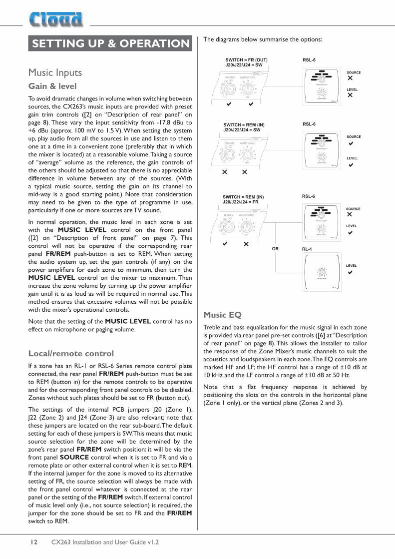
The settings of the internal PCB jumpers J20 (Zone 1), J22 (Zone 2) and J24 (Zone 3) are also relevant; note that these jumpers are located on the rear sub-board. The default setting for each of these jumpers is SW. This means that music source selection for the zone will be determined by the zone’s rear panel FR/REM switch position: it will be via the front panel SOURCE control when it is set to FR and via a remote plate or other external control when it is set to REM. If the internal jumper for the zone is moved to its alternative setting of FR, the source selection will always be made with the front panel control whatever is connected at the rear panel or the setting of the FR/REM switch. If external control of music level only (i.e., not source selection) is required, the jumper for the zone should be set to FR and the FR/REM switch to REM.
The diagrams below summarise the options:
Music EQTreble and bass equalisation for the music signal in each zone is provided via rear panel pre-set controls ([6] at “Description of rear panel” on page 8). This allows the installer to tailor the response of the Zone Mixer’s music channels to suit the acoustics and loudspeakers in each zone. The EQ controls are marked HF and LF; the HF control has a range of ±10 dB at 10 kHz and the LF control a range of ±10 dB at 50 Hz.
Note that a flat frequency response is achieved by positioning the slots on the controls in the horizontal plane (Zone 1 only), or the vertical plane (Zones 2 and 3).

CX263 Installation and User Guide v1.2 13
Microphone InputsPhantom PowerEach microphone input has 12 V phantom power available. This will be adequate to power a wide range of condenser microphones. (Some “studio quality” mics may require a higher phantom voltage and thus necessitate an external PSU.) To enable phantom power at the mic inputs, the internal PCB jumpers J1 (Mic 1) and/or J2 (Mic 2) should be moved to their ON positions. See “PCB jumper location and settings” on page 19 for jumper locations.
Phantom power should NOT be enabled if dynamic microphones are to be used.
Gain & levelEach microphone input is provided with a rear panel preset GAIN control ([4] at “Description of rear panel” on page 8). A wide range of gain is available (10 to 50 dB), and there should be no problem in obtaining a satisfactory level from any normal microphone.
The mic GAIN control should be adjusted by speaking normally into a microphone of the correct type. Start with it at minimum gain (fully anticlockwise), turn the corresponding front panel MIC LEVEL control up to maximum and listen in a convenient zone; the rear panel GAIN control should then be carefully advanced until the mic volume is as loud as it is ever likely to be needed, and then reduced slightly. There should be no audible distortion. The use to which the microphone is to be put should be borne in mind – karaoke is more likely to overload the mic preamplifier than spoken announcements, if the gain is not set correctly.
In normal operation, the mic level in each zone is set with the MIC 1 LEVEL and MIC 2 LEVEL controls on the front panel ([3] & [4] on “Description of front panel” on page 7).
Paging Access ControlOn the CX263, MIC1 input may be used for paging purposes. Paging microphones from the Cloud PM Series (and also the older CDPM Series) are fully compatible; OEM paging microphones using the “contact-closure” (short-to-ground) method of zone selection will also be suitable.
It should be noted that Cloud PM Series paging microphones will need to be connected using the “analogue” interface; the CX263 does not support the Cloud Digital Paging Interface also implemented on these models. Note also that microphones cannot be powered from the CX263; an external PSU will be required. Full details can be found in the PM Series Installation Guide.
Zone selection is made using the MIC 1 ACC connector ([7] at “Description of rear panel” on page 8). This is a 4-pin 3.81 mm-pitch screw terminal connector with pinout as follows:
PIN FUNCTION
1 0 V
2 Enable Zone 1
3 Enable Zone 2
4 Enable Zone 3
To enable Mic 1 input for paging, pin 2, 3 or 4 (or any combination thereof) should be connected to pin 1 (0 V). When the CX263 is shipped from the factory, the access contacts are bypassed by internal PCB jumpers; in order for the access port to operate correctly, these jumpers need to be removed. The jumpers are: J4 (Zone 1), J5 (Zone 2) and J6 (Zone 3); see “PCB jumper location and settings” on page 19 for their locations. It is recommended that when removed, the jumpers are stored on one pin of the PCB header in case the unit needs to be reconfigured in the future.
See also the manual section “Priorities” (page 14) for further information regarding configuring the CX263 for use with a paging microphone.
EQSeparate two-band equalisation adjustment is provided for each microphone input. The MICROPHONE EQ pre-set controls are on the front panel ([5] at page 7). The equalisation is optimised for the tonal correction of speech signals: the HF controls provide ±10 dB at 5 kHz whilst the LF controls provide ±10 dB at 100 Hz.
A tamperproof cover is supplied with the CX263; this can be fitted in place over the EQ controls once they have been adjusted to prevent further alteration.
To achieve a “flat” response for either microphone input, set the controls for that input to 0 dB (the ‘12 o’clock’ position).
High-pass filterEach mic input has a fixed 100 Hz high-pass filter to remove the lowest frequencies. This helps to reduce the effects of breath blasts and microphone handling noise. The filter is always in circuit.

CX263 Installation and User Guide v1.214
Zone OutputsIn normal operation, the music level in each zone will be set by the front panel MUSIC LEVEL control, or by a corresponding control on a remote plate. Follow the procedure described previously (“Gain & level” on page 12) to adjust the music level in each zone.
EQThe various zones in a building often have different acoustic properties, and may also have different models of loudspeaker installed. The CX263 is fitted with HF and LF EQ adjustments ([6] on “Description of rear panel” on page 8) for the music signal at each zone output, to enable the audio frequency response to be best matched to each zone. The controls should be adjusted by listening; up to 10 dB of cut or boost at 10 kHz (HF) and 50 Hz (LF) is available. Note that these EQ adjustments do not affect the frequency response of microphones or paging.
PrioritiesThe CX263 offers several options for determining what happens to music signals when announcements are made. The options are selected via internal jumpers, and should be set to suit the requirements of the installation when the system is installed. See “PCB jumper location and settings” on page 19 for location of the internal jumpers.
Line 6 priorityIt may sometimes be necessary for one music input to have priority over all the others; for example, a jukebox in a bar, or a digital sound store programmed to make automatic announcements in a public space. Line Input 6 may be set to have priority in any or all zones over whichever source is selected for the zone by its SOURCE control.
Line 6 priority can be enabled independently for each zone by moving internal PCB jumpers J10a & J10b (Zone 1), J8a & J8b (Zone 2) and J9a & J9b (Zone 3). Note that there are two physical jumpers per zone. The jumpers should be set to the ON position for Line 6 priority; the default setting is OFF.
When Line 6 priority is enabled, a signal present at the LINE 6 input will force the zone’s source selection to that input; when the signal disappears, the previously-selected source will be gradually restored over a period of 3, 6 or 12 seconds, as selected by internal PCB jumper J3. Note that the setting of J3 is applicable to all zones with the priority enabled.
Microphone 1 priorityMicrophone 1 input on the CX263 is automatically configured to take priority over both the music signals and Microphone 2. When the priority circuit is triggered, signals at MIC 2 input are effectively muted. See the next section for details of the effect on music signals in the zone.
Microphone 1 priority can be triggered either by signal detection (AVO) or the zone access contacts on the rear panel (ACC). Access-triggered priority should only be selected when a paging microphone is in use with the CX263. To configure Microphone 1 priority, internal PCB jumpers J18 (Zone 1), J17 (Zone 2) and J16 (Zone 3) should be set as required. (The jumpers are located behind the Microphone 1 level control for each zone.)
Jumper positions:
• AVO: the priority action is triggered when the access contact for that zone is shorted to ground and a signal is detected at the microphone input.
• ACC: the priority action is triggered as soon as the access contact for that zone is shorted to ground.
• OFF: This position is not marked, but can be achieved by removing the jumper altogether.
NOTE: It is recommended that if removed, the jumpers are stored on one pin of the PCB header in case the unit needs to be reconfigured in the future.
Mic-over-Music priorityBoth microphone inputs have priority over music signals. When the priority circuit is triggered, music signals in the respective zones are attenuated by 30 dB until the priority circuitry is released. Once priority has been released, the music signal will be smoothly restored to its former level, over the time period defined by the setting of J3 (see “Line 6 priority” on this page). Note that J3 defines the time constant for both Line 6 priority and Mic-over-Music priority.
A signal at MIC 2 input will trigger this priority circuit under all conditions. A signal at MIC 1 input may trigger the priority either via signal detection (AVO) or contact closure at the rear panel access contacts (ACC). See the previous section for details of how to configure the Mic 1 priority action.
If for any reason it is necessary to permanently disable the Mic-over-Music priority in a particular zone, an internal modification to the PCB can be made. Please refer to the Technical Notes section of the Resources page at www.cloud.co.uk for details.
CX263 Installation and User Guide v1.2 15
OPTIONS AND ADDITIONAL INFORMATIONCDI-S200 Serial Interface CardThe CDI-S200 is an optional RS-232C interface card designed specifically for use with the CX263. It can be retrofitted to the Zone Mixer at any time. It carries a 9-pin Dsub connector, which replaces the blanking plate adjacent to the mains connector on the rear panel. When installed, most of the CX263’s primary functions can be controlled with RS-232C serial commands, typically from AV control systems such as Crestron, AMX, etc.
For the CDI-S200 card to operate correctly, the settings of various internal jumpers need to be changed. Additionally, the FR/REM switches should be placed in the REM position, the DIG/AN switches in the DIG position for zones under serial control, and the Access Port jumpers J4, J5 and J6 set to ON as required.
A separate Installation Guide, including full setup and operating instructions is supplied with the CDI-S200 card.
RL-1 Series and RSL-6 Series remote control plates – general considerationsCloud RL-1 Series and RSL-6 Series remote control plates are available in three form factors: two fit single-gang UK or American electrical back boxes respectively, while the third is a 50 x 50 mm “Media” module, suitable for “Euro-module” mounting frames available in most European countries. Back boxes of either the recessed type or surface-mounting type may be used, providing they are at least 25 mm deep.
Each plate should be connected to the REMOTE port of the relevant zone using single- or twin-core screened cable as described at “Music Control” on page 10. The plate terminations are conventional screw terminals and the REMOTE port on the mixer is a 3-pin 5 mm-pitch screw terminal connector.
The remote control plates are passive and thus do not draw any significant current from the mixer.

CX263 Installation and User Guide v1.216
Control of music source and level via external DCIt may be necessary in some installations to adjust the music level and select music source in one or more zones from an external control system (e.g., Crestron, AMX, etc.). If the REMOTE ports are not required for RL-1/RSL-6 Series remote control plates, they may be used to receive DC voltages from the external system to effect these adjustments.
Both music source selection and level can be controlled over their full ranges with a DC voltage of 0 to +10 V. The pinout of the REMOTE port is as follows:
PIN USE
1 0 V ref.
2 Music level control (0 to +10 V)
3 Music source selection (0 to +10 V)
REMOTEPORT
1
23
+12 V
0 V MUSIC VCA
MUSIC SOURCESELECT
4k7 15kCONTROLSYSTEM
0 V REF
LEVEL CONTROL
SOURCE CONTROL
CX263
NOTE: If the control voltage source is not isolated from the power earth, there is a small risk of creating a ‘ground loop’ by linking the mixer technical ground (0 V) to the ground (0 V) of the equipment supplying the control voltages. To minimise this risk, we suggest that all pieces of equipment be in close proximity, and supplied from the same power outlet.
Music levelMusic level in a zone may be varied over its full range by applying a DC voltage of between 0 and +10 V to pin 2, the 0 V reference being connected to Pin 1. 0 V on pin 2 corresponds to full level and +10 V will produce maximum attenuation. Between these two voltages, the rate of attenuation is approximately 165 mV/dB.
Note that there is an internal 4k7 “pull-up” resistor between pin 2 and the internal +12 V rail. If pin 2 is left “floating”, this pull-up will result in full attenuation. The output impedance of the control voltage source should be low enough to overcome the effect of this resistor.

CX263 Installation and User Guide v1.2 17
Music sourceMusic source for a zone may be controlled by applying various DC voltages of between 0 and +10 V to pin 3, the 0 V reference being connected to pin 1. 0 V at pin 3 will select Line input 6 and between +7.5 and +9 V will select Line input 1. The other line inputs will be selected with intermediate voltages. Taking pin 3 above +9 V will deselect all inputs, making the zone effectively ‘off ’ for music.
The table below lists the DC voltages required at pin 3 to select each line input. The third column is the value of a resistor which should be connected between pins 1 and 3 to permanently ‘force’ a zone to a particular line input.
INPUT DC VOLTAGE RESISTOR VALUE
OFF >+9.0 V
Line 1 +7.5 V 16k
Line 2 +6.0 V 11k
Line 3 +4.5 V 6k8
Line 4 +3.0 V 3k9
Line 5 +1.5 V 1k8
Line 6 0 V short-circuit
Note that there is an internal 15k “pull-up” resistor between pin 3 and the internal +12 V rail. If pin 3 is left “floating”, this pull-up will cause ‘OFF’ to be selected. The output impedance of the control voltage source should be low enough to overcome the effect of this resistor.
Fitting loudspeaker EQ cardsThe CX263 is compatible with various popular installed-sound loudspeakers; a single-channel loudspeaker equalisation module may be fitted to any or all of the zone outputs to optimise the frequency response of the channel to the loudspeaker type being used.
Please check the Cloud website (www.cloud.co.uk/accessories) for makes and models of loudspeakers for which EQ cards are available.
To install equalisation modules, first remove the top cover from the CX263 (6 screws). The modules plug into the four empty, white 12-pin connectors in the centre of the main PCB. (Note that as Zone 1 is stereo it has two connectors.)
The connectors on the main PCB have two notches on one side only; these engage with lugs on the equalisation module’s mating connector to ensure correct orientation. To enable the modules, an associated PCB jumper must be removed; these are listed in the table below:
CONNECTOR ZONE JUMPER
CON3 Zone 1 Right J12
CON4 Zone 1 Left J13
CON5 Zone 2 J14
CON6 Zone 3 J15
See the Appendix section “PCB jumper locations and settings” at “PCB jumper location and settings” on page 19 for further details. Replace the top cover with the original screws after fitting.

CX263 Installation and User Guide v1.218
APPENDIX
Application example
MIC 1 IN
LINE 1
LINE 2
LINE 3
LINE 4
LINE 5
LINE 6
ZONE 1
ZONE 2
LR
REMOTE
REMOTE
MIC 1 ACCESS
MUSIC MUTE
AMPLIFIERS
CDPLAYER
MUSICSERVER
DTV BOX
SAT BOX
JUKEBOX
iPOD DOCK
FROM FIRE CONTROL PANEL
PAGING MIC
MUSIC SOURCES (all stereo)
2
2
2
2
2
2
MIC 2 IN
ADDITIONAL MIC
ZONE 3
REMOTE
ZONE 1
RSL-6
ZONE 2
ZONE 3
RL-1
RS-232 SERIAL REMOTE
FROM EXTERNAL CONTROL SYSTEM
(e.g. Crestron, AMX, etc.)
The example shows a CX263 used to provide music, announcements and paging in three separate areas (zones) of a premises such as a retail outlet. Area 1 is wired for stereo music, and can set its own music source and volume by means of the local RSL-6 remote control (optional). Areas 2 and 3 are mono only; Area 2 is fitted with an RL-1 remote control panel which allows local control of music level in that zone. Music sources and levels could be set from the front panel of the mixer itself if preferred.
Paging to any zone is achieved using a paging mic (such as the Cloud PM4) connected to Mic 1 input; this would typically be located somewhere other than within any one of the zones. Additional announcements to any zone can be made from the separate microphone connected at Mic 2 input.
Note that the jukebox is shown connected to Line input 6; if Line 6 Priority is enabled in the mixer, then whenever the jukebox is in use it will always be heard in Zone 1, regardless of the music source setting.

CX263 Installation and User Guide v1.2 19
PCB jumper location and settingsThe CX263 has various internal jumpers, the setting of which may require alteration during installation. The table below lists each switch and jumper and its purpose, together with the factory default setting.
JUMPER NAME EFFECT DEFAULT
Main PCB:
J1 Mic 1 phantom power OFF: Mic phantom power OFFON: Mic phantom power ON OFF
J2 Mic 2 phantom power
J3 Line 6 Priority release time3S: 3 seconds. release time6S: 6 seconds release timeABSENT: 12 seconds release time
3S
J4 Bypass Zone 1 AccessPRESENT: Access port disabled for relevant zoneABSENT: Access port enabled for relevant zone PRESENTJ5 Bypass Zone 2 Access
J6 Bypass Zone 3 Access
J7 Music Mute configuration N/O: contact closure required for mutingN/C: contact opening required for muting N/O
J8* Line 6 priority – Zone 2OFF: No priority in relevant zoneON: Line 6 has VOX-triggered priority in relevant zone over other sources OFFJ9* Line 6 priority – Zone 3
J10* Line 6 priority – Zone 1
J11 Zone 1 mono/stereo operation STEREO: Zone 1 stereo operationMONO: Zone 1 L & R channels summed
STEREO
J12 Bypass EQ card – Zone 1R
PRESENT: EQ card socket is bypassedABSENT: EQ card socket is enabled
PRESENTJ13 Bypass EQ card – Zone 1L
J14 Bypass EQ card – Zone 2
J15 Bypass EQ card – Zone 3
J16 Mic 1 priority trigger - Zone 3 VOX: Paging mic signal triggers priority in relevant zoneSW: Contact closure at Access Port enables paging mic priority in relevant zoneABSENT: Priority function disabled in relevant zone
VOXJ17 Mic 1 priority trigger - Zone 2
J18 Mic 1 priority trigger – Zone 1
Rear sub-board:
J19 Enable CDI-S200 music source selection – Zone 1
SW: Music source selection in relevant zone is determined by rear panel FR/REM switchDG: Music source selection in relevant zone is controlled by Serial Interface Card
SWJ21Enable CDI-S200 music source selection – Zone 2
J23Enable CDI-S200 music source selection – Zone 3
J20 Music source selection – Zone 1 SW: Music source selection in relevant zone follows rear panel FR/REM switchFR: Music source selection in relevant zone is always via front panel SOURCE control
SWJ22 Music source selection – Zone 2
J24 Music source selection – Zone 3
* J8 – J10 each consist of two jumpers; they should be moved as a pair

CX263 Installation and User Guide v1.220
The diagram below shows the locations of the CX263’s internal PCB jumpers (not to scale).
If any jumpers need to be changed, turn the Zone Mixer off and disconnect it from the mains. Undo the 6 screws securing the top cover of the unit and remove it. Use a pair of small pliers to gently remove the jumpers from the PCB headers and reposition them as required.
The diagram also shows the locations of the socket for the optional loudspeaker EQ cards.
FRONT OF UNIT
J1
J3
J2
J4J6 J5J7
Denotes 2-pin header: jumper may be present or absentDenotes 3-pin header: jumper may in one of two positions; black end indicates default setting
PCB LAYOUT DIAGRAM.ONLY PRIMARY COMPONENTS SHOWN.
NOT TO SCALE.
J8a J8b
J9a J9b
J10a J10b
J11
J12J13J14J15
J16
J17J18
J22J24 J23 J21J20
J19
CON6CON4CON5 CON3
Motherboard jumper locations
Ground loopsIf, despite your best efforts, the completed sound system ‘hums’ you probably have a ‘ground loop’. The offending signal source can often be identified by setting the volume control to minimum, then disconnecting the input leads (both left & right channels) on each line input until the ‘hum’ disappears. This problem is often caused by terminating a screened input cable into a signal source positioned a significant distance from the mixer. A good way of avoiding this potential problem is to use signal sources (CD players and the like) that are double insulated with no connection to the mains supply earth. If a signal feed were derived from a second mixer (a club or microphone mixer for example) it would be perfectly normal to expect this to be earthed; we suggest that a transformer be used to isolate the signal and prevent a noisy loop (see “Music Sources” on page 9).
EMC considerationsThe Cloud CX263 fully conforms to the relevant electromagnetic compatibility (EMC) standards and is technically well behaved; you should experience no operational problems and under normal circumstances, no special precautions need to be taken. If the unit is to be used within close proximity to potential sources of HF disturbance such as high power communications transmitters, radar stations and the like, the performance of the mixer may be reduced; we suggest that the microphone cable screen be connected to the equipment chassis and the line input leads are kept as short as possible.

CX263 Installation and User Guide v1.2 21
Technical SpecificationsLine Inputs:
Frequency response 20 Hz to 22 kHz, +0/-0.5 dBDistortion <0.05% typical, 20 Hz to 22 kHzSensitivity 100 mV (-17.8 dBu) to 1.5 V (+6 dBu)Input gain control range 24 dBInput impedance 48 kohmsHeadroom >20 dBNoise <-84 dB, 20 Hz to 22 kHz @ 0 dB gainEqualisation LF: +/-10 dB @ 50 Hz; HF: +/-10 dB @ 10 kHz
Microphone Inputs:
Frequency response -3 dB @ 100 Hz (filter) to 20 kHz, +/-0.5 dB Distortion <0.05%, 20 Hz to 22 kHzGain range 10 dB to 50 dBInput impedance >2 kohmsCommon mode rejection >70 dB @ 1 kHzHeadroom >20 dBNoise -128 dB EIN, 20 Hz to 22 kHz @ 0dB gainEqualisation LF: +/-10 dB @ 150 Hz; HF: +/-10 dB @ 5 kHz
Outputs:
Output level (nominal) 0 dBu
Output level (max.) +20 dBu
Minimum load impedance 1.2 kohms
General:
Power input 85 V to 253 V AC, 50/60 Hz
Current consumption 43.1 mA at 240 V
Fuse rating 1 A
Fuse type T1A, 20 x 5 mm
Dimensions (WxHxD) 482.6 mm x 44 mm (1U) x 152.5 mm19” x 1.73” (1U) x 6”
Weight 2.13 kg4.66 lbs

www.cloud.co.uk www.cloudusa.pro