CWNA Guide to Wireless LANs, Second Edition Chapter Six Planning and Deploying a Wireless LAN.
date post
20-Dec-2015Category
view
225download
4
CWNA Guide to Wireless LANs, Second Edition
(Modified Spring 2007)
Chapter ThreeHow Wireless Works

CWNA Guide to Wireless LANs, Second Edition
CCRI J. Bernardini
2
Objectives
• Explain the principals of radio wave transmissions• Describe RF loss and gain, and how it can be
measured• List some of the characteristics of RF antenna
transmissions• Describe the different types of antennas• Understanding principles of radio wave
transmission is important for: – Troubleshooting wireless LANs – Creating a context for understanding wireless terminology

CWNA Guide to Wireless LANs, Second Edition
CCRI J. Bernardini
3
What Are Radio Waves?
• Electromagnetic wave: Travels freely through space in all directions at speed of light
• Radio wave: When electric current passes through a wire it creates a magnetic field around the wire– As magnetic field radiates, creates an electromagnetic radio
wave • Spreads out through space in all directions
– Can travel long distances– Can penetrate non-metallic objects

CWNA Guide to Wireless LANs, Second Edition
CCRI J. Bernardini
4
Analog vs. Digital Transmissions
Digital Signal = A signal in which information is carried in a limited number of different discrete states or levels; High/Low, One/Zero, 1/0
Analog Signal = A signal that has continuously varying voltages, frequencies, or phases. All amplitude values are present from minimum to maximum signal levels.

CWNA Guide to Wireless LANs, Second Edition
CCRI J. Bernardini
5
Analog vs. Digital Transmissions
• Analog Transmission use analog carrier signals and analog modulation.
• Digital Transmission use analog carrier signals and digital modulation.
• Modem (MOdulator/DEModulator): Used when digital signals must be transmitted over analog medium– On originating end, converts distinct digital signals into
continuous analog signal for transmission– On receiving end, reverse process performed
• WLANs use digital modulation of analog signals (carrier signal)

CWNA Guide to Wireless LANs, Second Edition
CCRI J. Bernardini
6
Frequency
• Frequency: f= Rate at which an event occurs f =1/T
• Cycle: Changing event that creates different radio frequencies– When wave completes trip and returns back to starting point it
has finished one cycle
• Period: T=The time to complete one cycle T=1/f• Hertz (Hz): Cycles per second
– Kilohertz (KHz) = thousand hertz– Megahertz (MHz) = million hertz– Gigahertz (GHz) = billion hertz

CWNA Guide to Wireless LANs, Second Edition
CCRI J. Bernardini
7
Frequency and Period

CWNA Guide to Wireless LANs, Second Edition
CCRI J. Bernardini
8
Frequency

CWNA Guide to Wireless LANs, Second Edition
CCRI J. Bernardini
9
Electrical terminology

CWNA Guide to Wireless LANs, Second Edition
CCRI J. Bernardini
10
Modulation
• Carrier signal is a continuous electrical signal– Carries no information
• Three types of modulations enable carrier signals to carry information– Height of signal– Frequency of signal– Relative starting point
• Modulation can be done on analog or digital transmissions

CWNA Guide to Wireless LANs, Second Edition
CCRI J. Bernardini
11
Analog Modulation
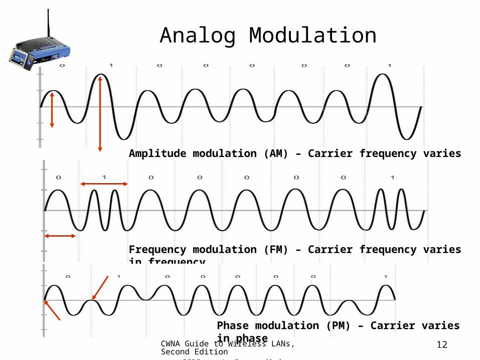
• Amplitude: Height of carrier wave• Amplitude modulation (AM): Changes
amplitude so that highest peaks of carrier wave represent 1 bit while lower waves represent 0 bit
• Frequency modulation (FM): Changes number of waves representing one cycle– Number of waves to represent 1 bit more than number of waves
to represent 0 bit
• Phase modulation (PM): Changes starting point of cycle– When bits change from 1 to 0 bit or vice versa
CWNA Guide to Wireless LANs, Second Edition
CCRI J. Bernardini
12
Analog Modulation
Amplitude modulation (AM) – Carrier frequency varies in amplitude
Frequency modulation (FM) – Carrier frequency varies in frequency
Phase modulation (PM) – Carrier varies in phase

CWNA Guide to Wireless LANs, Second Edition
CCRI J. Bernardini
13
Digital Modulation
• Advantages over analog modulation:– Better use of bandwidth– Requires less power– Better handling of interference from other signals– Error-correcting techniques more compatible with other digital
systems
• Unlike analog modulation, changes occur in discrete steps using binary signals– Uses same three basic types of modulation as analog
Amplitude shift keying (ASK)

CWNA Guide to Wireless LANs, Second Edition
CCRI J. Bernardini
14
Digital Modulation
Frequency shift keying (FSK)
Phase shift keying (PSK)

CWNA Guide to Wireless LANs, Second Edition
CCRI J. Bernardini
15
Radio Frequency Behavior: Gain
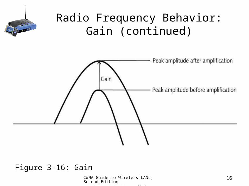
• Gain: Positive difference in amplitude between two signals– Achieved by amplification of signal– Technically, gain is measure of amplification– Can occur intentionally from external power source that
amplifies signal– Can occur unintentionally when RF signal bounces off an object
and combines with original signal to amplify it
CWNA Guide to Wireless LANs, Second Edition
CCRI J. Bernardini
16
Radio Frequency Behavior: Gain (continued)
Figure 3-16: Gain

CWNA Guide to Wireless LANs, Second Edition
CCRI J. Bernardini
17
Radio Frequency Behavior: Loss
• Loss: Negative difference in amplitude between signals– Attenuation– Can be intentional or unintentional– Intentional loss may be necessary to decrease signal strength to
comply with standards or to prevent interference– Unintentional loss can be cause by many factors

CWNA Guide to Wireless LANs, Second Edition
CCRI J. Bernardini
18
Radio Frequency Behavior: Loss (continued)
Figure 3-18: Absorption

CWNA Guide to Wireless LANs, Second Edition
CCRI J. Bernardini
19
Radio Frequency Behavior: Loss (continued)
Figure 3-19: Reflection

CWNA Guide to Wireless LANs, Second Edition
CCRI J. Bernardini
20
Radio Frequency Behavior: Loss (continued)
Figure 3-20: Scattering

CWNA Guide to Wireless LANs, Second Edition
CCRI J. Bernardini
21
Radio Frequency Behavior: Loss (continued)
Figure 3-21: Refraction

CWNA Guide to Wireless LANs, Second Edition
CCRI J. Bernardini
22
Radio Frequency Behavior: Loss (continued)
Figure 3-22: Diffraction
CWNA Guide to Wireless LANs, Second Edition
CCRI J. Bernardini
23
Radio Frequency Behavior: Loss (continued)
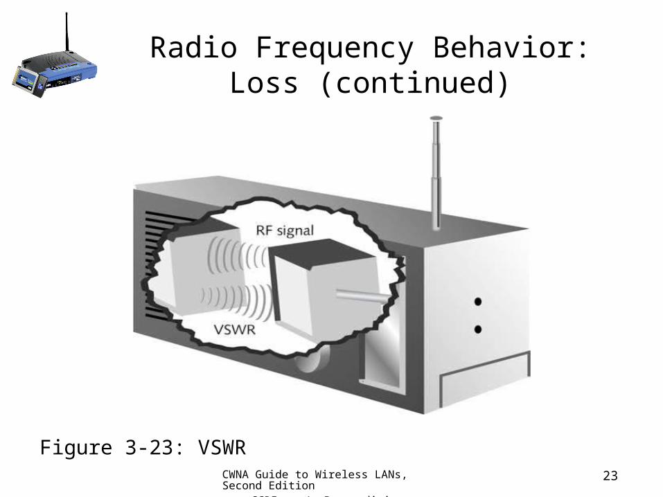
Figure 3-23: VSWR

CWNA Guide to Wireless LANs, Second Edition
CCRI J. Bernardini
24
RF Measurement: RF Math
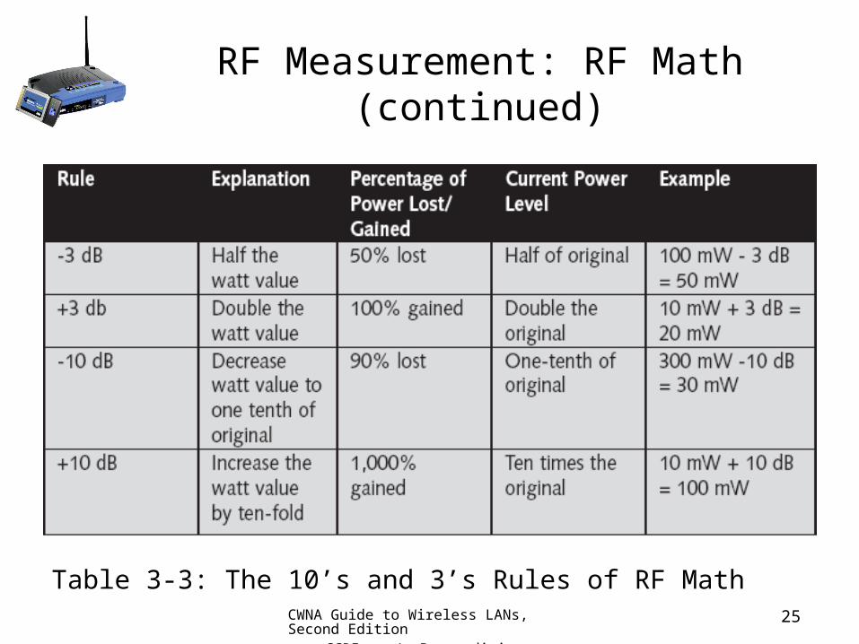
• RF power measured by two units on two scales:– Linear scale:
• Using milliwatts (mW)• Reference point is zero• Does not reveal gain or loss in relation to whole
– Relative scale: • Reference point is the measurement itself• Often use logarithms• Measured in decibels (dB)
• 10’s and 3’s Rules of RF Math: Basic rule of thumb in dealing with RF power gain and loss
CWNA Guide to Wireless LANs, Second Edition
CCRI J. Bernardini
25
RF Measurement: RF Math (continued)
Table 3-3: The 10’s and 3’s Rules of RF Math

CWNA Guide to Wireless LANs, Second Edition
CCRI J. Bernardini
26
RF Measurement: RF Math (continued)
• dBm: Reference point that relates decibel scale to milliwatt scale
• Equivalent Isotropically Radiated Power (EIRP): Power radiated out of antenna of a wireless system– Includes intended power output and antenna gain– Uses isotropic decibels (dBi) for units
• Reference point is theoretical antenna with 100 percent efficiency

CWNA Guide to Wireless LANs, Second Edition
CCRI J. Bernardini
27
RF Measurement: WLAN Measurements
• In U.S., FCC defines power limitations for WLANs– Limit distance that WLAN can transmit
• Transmitter Power Output (TPO): Measure of power being delivered to transmitting antenna
• Receive Signal Strength Indicator (RSSI): Used to determine dBm, mW, signal strength percentage
Table 3-4: IEEE 802.11b and 802.11g EIRP
CWNA Guide to Wireless LANs, Second Edition
CCRI J. Bernardini
28
Antenna Concepts
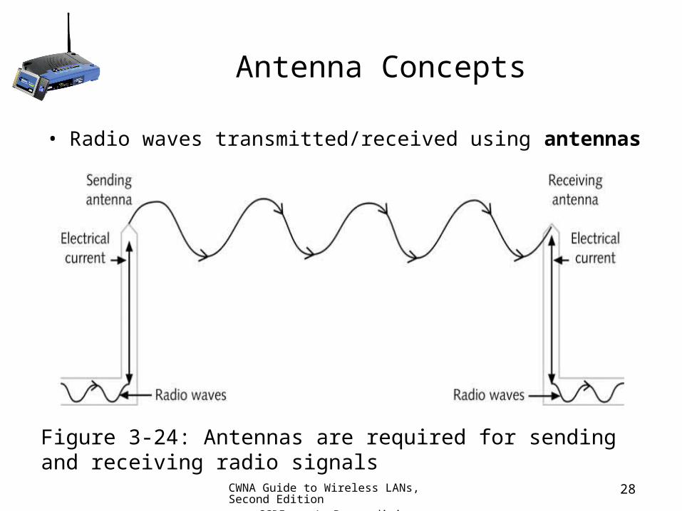
• Radio waves transmitted/received using antennas
Figure 3-24: Antennas are required for sending and receiving radio signals

CWNA Guide to Wireless LANs, Second Edition
CCRI J. Bernardini
29
Characteristics of RF Antenna Transmissions
• Polarization: Orientation of radio waves as they leave the antenna
Figure 3-25: Vertical polarization
CWNA Guide to Wireless LANs, Second Edition
CCRI J. Bernardini
30
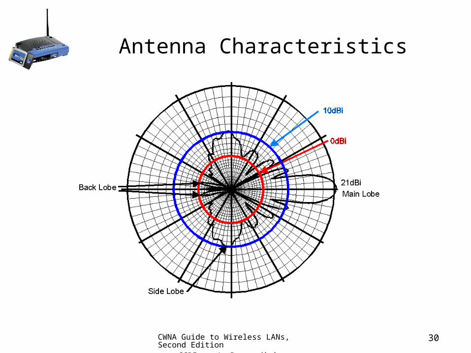
Antenna Characteristics
CWNA Guide to Wireless LANs, Second Edition
CCRI J. Bernardini
31
Characteristics of RF Antenna Transmissions (continued)
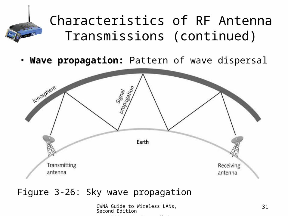
• Wave propagation: Pattern of wave dispersal
Figure 3-26: Sky wave propagation

CWNA Guide to Wireless LANs, Second Edition
CCRI J. Bernardini
32
Characteristics of RF Antenna Transmissions (continued)
Figure 3-27: RF LOS propagation
CWNA Guide to Wireless LANs, Second Edition
CCRI J. Bernardini
33
Characteristics of RF Antenna Transmissions (continued)
• Because RF LOS propagation requires alignment of sending and receiving antennas, ground-level objects can obstruct signals– Can cause refraction or diffraction– Multipath distortion: Refracted or diffracted signals reach
receiving antenna later than signals that do not encounter obstructions
• Antenna diversity: Uses multiple antennas, inputs, and receivers to overcome multipath distortion

CWNA Guide to Wireless LANs, Second Edition
CCRI J. Bernardini
34
Characteristics of RF Antenna Transmissions (continued)
• Determining extent of “late” multipath signals can be done by calculating Fresnel zone
Figure 3-28: Fresnel zone

CWNA Guide to Wireless LANs, Second Edition
CCRI J. Bernardini
35
Characteristics of RF Antenna Transmissions (continued)
• As RF signal propagates, it spreads out– Free space path loss: Greatest source of power loss in a
wireless system– Antenna gain: Only way for an increase in amplification by
antenna• Alter physical shape of antenna
– Beamwidth: Measure of focusing of radiation emitted by antenna
• Measured in horizontal and vertical degrees

CWNA Guide to Wireless LANs, Second Edition
CCRI J. Bernardini
36
Characteristics of RF Antenna Transmissions (continued)
Table 3-5: Free space path loss for IEEE 802.11b and 802.11g WLANs
CWNA Guide to Wireless LANs, Second Edition
CCRI J. Bernardini
37
Antenna Types and Their Installations
• Two fundamental characteristics of antennas:– As frequency gets higher, wavelength gets smaller
• Size of antenna smaller
– As gain increases, coverage area narrows• High-gain antennas offer larger coverage areas than low-gain
antennas at same input power level
• Omni-directional antenna: Radiates signal in all directions equally– Most common type of antenna

CWNA Guide to Wireless LANs, Second Edition
CCRI J. Bernardini
38
Antenna Types and Their Installations
• Semi-directional antenna: Focuses energy in one direction– Primarily used for short and medium range remote wireless
bridge networks
• Highly-directional antennas: Send narrowly focused signal beam– Generally concave dish-shaped devices– Used for long distance, point-to-point wireless links

CWNA Guide to Wireless LANs, Second Edition
CCRI J. Bernardini
39
Antenna Issues (cont.)
• Antennas have gain in particular directions
• Direction other than the main intended radiation pattern, are typically related to the main lobe gain
Linux+ Guide to Linux Certification, Second Edition
CWNA Guide to Wireless LANs, Second Edition
CCRI J. Bernardini
Antenna Gain
• If the gain of an antenna goes up, the coverage area or angle goes down
• Coverage areas or radiation patterns are measured in degrees
• Angles are referred to as beamwidth– Horizontal measurement– Vertical measurement

Linux+ Guide to Linux Certification, Second Edition
CWNA Guide to Wireless LANs, Second Edition
CCRI J. Bernardini
Antenna Theory
• A theoretical isotropic antenna has a perfect 360º vertical and horizontal beamwidth
• This is a reference for ALL antennas

Linux+ Guide to Linux Certification, Second Edition
CWNA Guide to Wireless LANs, Second Edition
CCRI J. Bernardini
Antenna Theory- Dipole
• Energy lobes are ‘pushed in’ from the top and bottom
• Higher gain– Smaller vertical
beamwidth– Larger horizontal lobe
• Typical dipole pattern
Side View(Vertical Pattern)
Top View(Horizontal Pattern)
New Pattern (with Gain)
Vertical Beamwidth
Linux+ Guide to Linux Certification, Second Edition
CWNA Guide to Wireless LANs, Second Edition
CCRI J. Bernardini
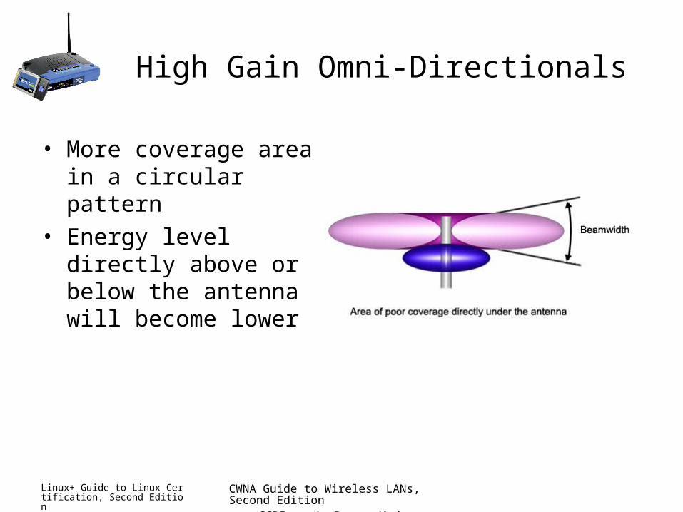
High Gain Omni-Directionals
• More coverage area in a circular pattern
• Energy level directly above or below the antenna will become lower

Linux+ Guide to Linux Certification, Second Edition
CWNA Guide to Wireless LANs, Second Edition
CCRI J. Bernardini
Directional Antennas
• Lobes are pushed in a certain direction, causing the energy to be condensed in a particular area
• Very little energy is in the back side of a directional antenna
Side View(Vertical Pattern)
Top View(Horizontal Pattern)

CWNA Guide to Wireless LANs, Second Edition
CCRI J. Bernardini
45
WLAN Antenna Locations and Installation
• Because WLAN systems use omni-directional antennas to provide broadest area of coverage, APs should be located near middle of coverage area
• Antenna should be positioned as high as possible• If high-gain omni-directional antenna used, must
determine that users located below antenna area still have reception

CWNA Guide to Wireless LANs, Second Edition
CCRI J. Bernardini
46
Summary
• A type of electromagnetic wave that travels through space is called a radiotelephony wave or radio wave
• An analog signal is a continuous signal with no breaks in it
• A digital signal consists of data that is discrete or separate, as opposed to continuous
• The carrier signal sent by radio transmissions is simply a continuous electrical signal and the signal itself carries no information

CWNA Guide to Wireless LANs, Second Edition
CCRI J. Bernardini
47
Summary (continued)
• Three types of modulations or changes to the signal can be made to enable it to carry information: signal height, signal frequency, or the relative starting point
• Gain is defined as a positive difference in amplitude between two signals
• Loss, or attenuation, is a negative difference in amplitude between signals
• RF power can be measured by two different units on two different scales

CWNA Guide to Wireless LANs, Second Edition
CCRI J. Bernardini
48
Summary (continued)
• An antenna is a copper wire or similar device that has one end in the air and the other end connected to the ground or a grounded device
• There are a variety of characteristics of RF antenna transmissions that play a role in properly designing and setting up a WLAN