A Low-Cost Approach to FMCW Radar: Through-Wall Microwatt Radar
CW/FMCW/Pulse Radar Engines for 24/26GHz Multi-Standard Applications in 65nm CMOS
Li-Yang Chen, Pen-Jui Peng, Chiro Kao, Yu-Lun Chen, and Jri Lee
Graduate Institute of Electronics Engineering, National Taiwan University, Taipei, Taiwan
Abstract —Two radar engines targeting CW/FMCW/pulse
structures have been reported in this paper for 24/26GHz multi-standard applications. Temperature compensation, injection-locking PLL, and Butler matrix techniques have been adopted in this work to achieve full operation with remarkable performance.
Index Terms —Butler matrix, continuous-wave (CW) radar, CMOS, frequency modulated (FMCW) continuous-wave radar, pulse radar, subharmonically injection-locked phase-locked loop, temperature compensation.
I. INTRODUCTION
K- and W-band radars have found extensive usage in automotive and traffic industries. While continuous-wave (CW) and frequency-modulated continuous-wave (FMCW) radars have been used in speed enforcement and anti-collision applications, pulse radars can be applied in parking assist systems (PAS) to replace ultrasonic modules. All of these radars are required to provide stable performance over temperature variation and low-jitter carriers to achieve accuracy. This paper presents two radar structures which share most of the building blocks and reveal universal solutions for CW/FMCW/pulse applications from 24 to 26GHz.
II. RADAR ARCHITECTURES
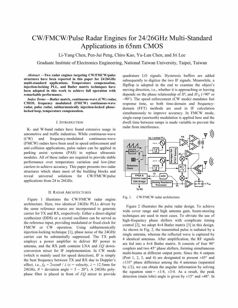
Figure 1 illustrates the CW/FMCW radar engine architecture. Here, two identical 24GHz PLLs driven by the same reference source are incorporated to generate carrier for TX and RX, respectively. Either a direct-digital synthesizer (DDS) or a crystal oscillator can be served as the reference input, providing modulated or fixed clock for FMCW or CW operation. Using subharmonically injection-locking technique [1], phase noise of the 24GHz carrier can be substantially suppressed. The TX path employs a power amplifier to deliver RF power to antenna, and the RX path contains LNA and I/Q down-conversion mixer for IF implementation. In CW mode (which is mainly used for speed detection), IF is simply the beat frequency between TX and RX due to Doppler’s effect, i.e., fIF = 2νcosθ / λ (ν = velocity, λ = 12.5mm for 24GHz, θ = deviation angle = 5 ~ 20°). A 24GHz poly-phase filter is placed in front of I/Q mixer to provide
quadrature LO signals. Hysteresis buffers are added subsequently to digitize the two IF signals. Meanwhile, a flipflop is adopted in the end to examine the object’s moving direction, i.e., whether it is approaching or leaving depends on the phase relationship of IFI and IFQ (+90° or −90°). The speed enforcement (CW mode) mandates fast response time, so both time-domain and frequency-domain (FFT) methods are used in IF calculation simultaneously to improve accuracy. In FMCW mode, single-ramp (sawtooth) modulation is applied here and the dwell time between ramps is made variable to prevent the radar from interference.
Fig. 1. CW/FMCW radar architecture. Figure 2 illustrates the pulse radar design. To achieve
wide cover range and high antenna gain, beam-steering techniques are used in most cases. To obviate the use of high-frequency phase shifters with complicate timing control [2], we adopt 4×4 Butler matrix [3] in this design. As shown in Fig. 2, the transmitted pulse is radiated by a single antenna, whereas the reflected wave is captured by 4 identical antennas. After amplification, the RF signals are fed into a 4×4 Butler matrix. It consists of four 90° couplers and two 45° phase shifters, forming simultaneous multi-beams at different output ports. Since the 4 outputs (Port 1, 2, 3, and 4) are designated to present ±45° and ±135° phase difference among the 4 antennas (separated by λ/2), we can obtain the angular information by solving the equation sinα = ±1/4, ±3/4. As a result, the peak detection (main lobe) angle is given by ±15° and ±48°. In
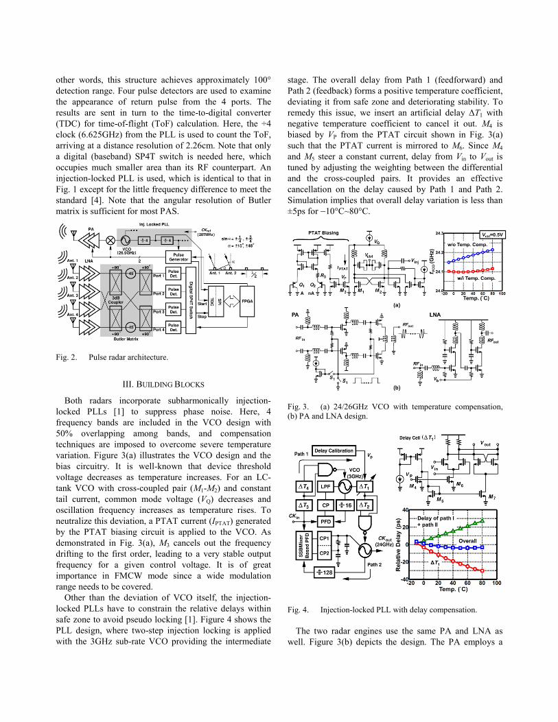
other words, this structure achieves approximately 100° detection range. Four pulse detectors are used to examine the appearance of return pulse from the 4 ports. The results are sent in turn to the time-to-digital converter (TDC) for time-of-flight (ToF) calculation. Here, the ÷4 clock (6.625GHz) from the PLL is used to count the ToF, arriving at a distance resolution of 2.26cm. Note that only a digital (baseband) SP4T switch is needed here, which occupies much smaller area than its RF counterpart. An injection-locked PLL is used, which is identical to that in Fig. 1 except for the little frequency difference to meet the standard [4]. Note that the angular resolution of Butler matrix is sufficient for most PAS.
Fig. 2. Pulse radar architecture.
III. BUILDING BLOCKS
Both radars incorporate subharmonically injection-locked PLLs [1] to suppress phase noise. Here, 4 frequency bands are included in the VCO design with 50% overlapping among bands, and compensation techniques are imposed to overcome severe temperature variation. Figure 3(a) illustrates the VCO design and the bias circuitry. It is well-known that device threshold voltage decreases as temperature increases. For an LC-tank VCO with cross-coupled pair (M1-M2) and constant tail current, common mode voltage (VQ) decreases and oscillation frequency increases as temperature rises. To neutralize this deviation, a PTAT current (IPTAT) generated by the PTAT biasing circuit is applied to the VCO. As demonstrated in Fig. 3(a), M3 cancels out the frequency drifting to the first order, leading to a very stable output frequency for a given control voltage. It is of great importance in FMCW mode since a wide modulation range needs to be covered.
Other than the deviation of VCO itself, the injection-locked PLLs have to constrain the relative delays within safe zone to avoid pseudo locking [1]. Figure 4 shows the PLL design, where two-step injection locking is applied with the 3GHz sub-rate VCO providing the intermediate
stage. The overall delay from Path 1 (feedforward) and Path 2 (feedback) forms a positive temperature coefficient, deviating it from safe zone and deteriorating stability. To remedy this issue, we insert an artificial delay ΔT1 with negative temperature coefficient to cancel it out. M4 is biased by VP from the PTAT circuit shown in Fig. 3(a) such that the PTAT current is mirrored to M6. Since M4 and M5 steer a constant current, delay from Vin to Vout is tuned by adjusting the weighting between the differential and the cross-coupled pairs. It provides an effective cancellation on the delay caused by Path 1 and Path 2. Simulation implies that overall delay variation is less than ±5ps for −10°C~80°C.
Fig. 3. (a) 24/26GHz VCO with temperature compensation, (b) PA and LNA design.
Fig. 4. Injection-locked PLL with delay compensation.
The two radar engines use the same PA and LNA as well. Figure 3(b) depicts the design. The PA employs a

two-stage common-source structure with on-chip transformer to convert the differential input into single-ended output. Switched bias circuits are used here for pulse radar, which only turns on the PA for 0.06% period of time. The LNA incorporates a 2-stage cascode structure with matching network, consuming only 9mW of power. For speed enforcement application, the horizontal (H-plane) radiation must present a −3-dB bandwidth of less than 6°, whereas the vertical (E-plane) has to reveal sidelobe level better than −15dBc. A 28×4 patch antenna array has been designed and fabricated in a low-loss material (εr = 2.2 and loss tangent = 0.0009) based on typical specification, arriving at measured −3-dB beamwidth and sidelobe of 4.3° and −18.1dBc, respectively. The pulse radar utilizes antennas of single-element patch for TX and 1×4 patch array for RX with bonding wire mismatch compensation.
IV. EXPERIMENTAL RESULTS
Both radar chipsets have been fabricated in 65-nm CMOS technology. The CW/FMCW TX and RX occupy 1.1 and 0.9mm2 and consume 254 and 115mW of power, respectively. The pulse radar TRX, on the other hand, occupies 1.6mm2 and consumes 149mW of power under pulse modulation with 0.06% duty cycle.
A. PLL Figure 5 shows the measurement results of the 24GHz
PLL. With frequency compensation technique, operation range varies by only 0.32% for the entire temperature range of −10°C~80°C. Figure 5(b) shows the rms jitter of the 24GHz carrier integrated from 100Hz to 1GHz offset with and without subharmonic injection.
Fig. 5. 24GHz PLL measurements: (a) operation range, (b) rms jitter.
B. CW/FMCW radar Figure 6(a) presents the IFI and IFQ signals for CW
mode, revealing the moving direction is fully detected. The radiation pattern of the 28×4 patch array antenna is plotted in Fig. 6(b), implying –3-dB beamwidth and sidelobe of 4.3° and –18.1dBc, respectively. The
measured FMCW spread spectrum of transmitter output is shown in Fig. 6(c), which presents 250-MHz spreading range and ramp modulation with 5-ms period. The received IF signal from 7-m away target is shown in Fig. 6(d). Figure 7(a) shows the testing setup of the overall CW radar module. The distance between radar module and vehicle is 2 m to 10m at its point of closest approach. The incidence angle is 20°. Figure 7(b) shows the measurement result. To verify the speed accuracy, we compare the speed with laser speed gun at the same time, and the relative error is less than 3km/h.
Fig. 6. Measurement results of CW mode: (a) IF signals, (b) antenna radiation pattern. FMCW mode: (c) spread spectrum, (d) IF signal.
Fig. 7. Overall CW radar measurement: (a) testing setup, (b) measurement result.
C. Pulse radar The 26.5GHz pulse radar’s performance is also
recorded. Figure 8(a) illustrates the TX spectrum, which is

measured by on-wafer probing. At least 10dB margin is left for antenna if the −41.3dBm/MHz mask is applied [4]. The RX antenna pattern is plotted in Fig. 8(b), implying −3-dB total beamwidth of 86°. Figure 9(a) shows the measurement setup for the detectable region. Here, an object with effective reflection area of 0.06m2 is detected at different positions. The direction of the object can be identified at the distance of 1m [Fig. 9(b)]. Figure 10 demonstrates the die photos and compares these two radar engines with other state of the arts.
Fig. 8. Pulse radar measurements: (a) TX spectrum with 600-ps pulsewidth and 1-MHz repetition rate, (b) RX antenna pattern.
Fig. 9. (a) System measurement setup, (b) detectable region for each port.
Fig. 10. Die photos and performance summary.
ACKNOWLEDGEMENT
The authors thank the TSMC University Shuttle Program for chip fabrication.
REFERENCES
[1] J. Lee and H. Wang, “Study of subharmonically injection-locked PLLs,” IEEE J. Solid-State Circuits, vol. 44, No. 5, pp.1539-1553, May 2009.
[2] Pang-Ning Chen, Pen-Jui Peng, Chiro Kao, Yu-Lun Chen, Jri Lee, “A 94GHz 3D-Image Radar Engine with 4TX/4RX Beamforming Scan Technique in 65nm CMOS,” ISSCC Dig. Tech. Papers, pp. 146-147, Feb. 2013.
[3] H. Krishnaswamy and H. Hashemi, “A 4-channel 4-beam 24-to-26GHz spatio-temporal RAKE radar transceiver in 90nm CMOS for vehicular radar applications,” ISSCC Dig. Tech. Papers, pp. 214 –215, Feb. 2010.
[4] “First report and order, revision of part 15 of the Commission’s rules regarding ultra wideband transmission systems,” FCC, Washington, DC, ET Docket 98–153, 2002.
[5] Gitae Pyo et-al, “K-band FMCW radar CMOS front-end ICs with 13.3 dBm output power,” in IEEE RFIC Symp. Dig., pp. 79–82, June 2014.