CVHE Teardown
30
Centravac General Service Literature Service Guide 1 TM Centravac General Service Literature CTVH-GCO-01-EN CVHE/CVHG Compressor Disassembly (Including): • Economizer Removal • Suction Elbow Removal • Compressor Disassembly • Unit Mounted Starter Removal • Motor Removal • Discharge Volute Removal CVHE (E-Design And Later), CVHG And CDHG Duplex Unit Compressor Sizes 013-140 and 350-1280 Ton This section describes disassembly (including economizer, suction elbow, unit mounted starter, motor, and discharge volute removal) procedures for the model CVHE AND CVHG CenTraVac compressor assemblies. The same information applies to the compressors for the CDHG duplex units. For disassembly and re-assembly procedures for the motor, see Centravac Service Literature Section CTVH-GMO-01. The procedures covered in this section may be used for the CVHE (E design sequence and later) and all CVHG compressor sizes (013 through 140) and (130 through 1250) tons. For information on the CVHF compressors, see Centravac Literature Sections CTVH-GCO-03, 04 for compressor sizes (350 through 1280) and CTVH-GCO-05 & 06 for the extended capacity compressor sizes 1470 and 1720. The CVHE AND CVHG compressors are similar in construction. Always check the appropriate table to obtain weights and tolerances for a particular type or size compressor. Warning and Cautions WARNINGs and CAUTIONs appear at appropriate sections throughout this manual. Read these carefully. WARNING: indicates a potentially hazardous situation which, if not avoided, could result in death or serious injury. CAUTION: indicates a potentially hazardous situation which, if not avoided, may result in minor or moderate injury. CAUTION: may also be used to alert the reader to a situation that could result in equipment or property-only damage.
-
Upload
bgottlieb420 -
Category
Documents
-
view
2.021 -
download
25
Transcript of CVHE Teardown
Centravac General Service Literature
TM
Centravac General Service Literature CTVH-GCO-01-EN
CVHE/CVHG Compressor Disassembly (Including):
• Economizer Removal
• Suction Elbow Removal
• Compressor Disassembly
• Unit Mounted Starter Removal
• Motor Removal
• Discharge Volute Removal
CVHE (E-Design And Later), CVHG And CDHG Duplex Unit Compressor Sizes 013-140 and 350-1280 Ton
This section describes disassembly (including economizer, suction elbow, unit mounted starter, motor, and discharge volute removal) procedures for the model CVHE AND CVHG CenTraVac compressor assemblies. The same information applies to the compressors for the CDHG duplex units. For disassembly and re-assembly procedures for the motor, see Centravac Service Literature Section CTVH-GMO-01. The procedures covered in this section may be used for the CVHE (E design sequence and later) and all CVHG compressor sizes (013 through 140) and (130 through 1250) tons. For information on the CVHF compressors, see Centravac Literature Sections CTVH-GCO-03, 04 for compressor sizes (350 through 1280) and CTVH-GCO-05 & 06 for the extended capacity compressor sizes 1470 and 1720.
The CVHE AND CVHG compressors are similar in construction. Always check the appropriate table to obtain weights and tolerances for a particular type or size compressor.
Warning and Cautions
WARNINGs and CAUTIONs appear at appropriate sections throughout this manual. Read these carefully.
WARNING: indicates a potentially hazardous situation which, if not avoided, could
result in death or serious injury.
CAUTION: indicates a potentially hazardous situation which, if not avoided, may
result in minor or moderate injury.
CAUTION: may also be used to alert the reader to a situation that could result in
equipment or property-only damage.
Service Guide 1
Centravac General Service Literature
TM
Disassembly.
Refer to CenTraVac General Literature Section CTVH-GMS-01 for details on the special lifting fixtures for removing the first stage inlet vane assembly and handling the compressor suction cover and casing components. The tools shown can be fabricated locally using the drawings found in the special tools section. The Trane Company assumes no responsibility for the use of materials that do not meet the required specifications, or for improper or faulty manufacturing, assembly or use of these lifting fixtures. Never exceed the maximum safe lifting capacity of the fixture.
IMPORTANT: Some of the lifting tools built for the CVHE compressor components have a maximum lifting capacity of 1300 lb. The tool maximum weight capacity is stamped on the tool. Some CVHG castings exceed this rating and the lifting tool given in Literature Section CTVH-GMS-01 must be used.
WARNINGHEAVY OBJECTS!Use lifting and rigging equipment that is rated to handle the maximum weights. Improper use of lifting fixtures may result in death or serious injury.
Follow all proper procedures when handling large compressor components. Use lifting and rigging equipment that is rated to handle the maximum weights of the pieces found in Table 2 in the back of this literature section. It is recommended that all lifting devices have a capacity rating no less than 100% of the weights shown. Carefully inspect lifting equipment to ensure it is in good condition and has been certified for continued use at proper intervals.
1 It may be advisable to obtain vibration readings for reference purposes prior to disassembly. See General Service Bulletin CVHE-SB-18 (latest revision) for information on allowable vibration limits.
WARNINGHAZARDOUS VOLTAGE!Disconnect all electrical power, including remote dis-connects, before servicing. Follow proper lockout/tagout procedures to ensure the power cannot be inadvertently energized. Failure to disconnect power before servicing could result in death or serious injury.
IMPORTANT: Be sure to properly lock out ALL potentially hazardous energy sources before servicing is done on the equipment. Follow all proper refrigerant handling procedures. Before disassembly, evacuate the unit to 2.5 mm vacuum and bring the unit back up to atmospheric pressure using dry nitrogen.
CTVH-GCO-01-EN2
Centravac General Service Literature
TM
2 Mark and disconnect all power leads to the inlet vane actuator motor. Remove the conduit assembly from the actuator motor.
3 Remove the inlet vane actuator linkages.
(a) Disconnect the universal joints at the inlet vane operator levers.
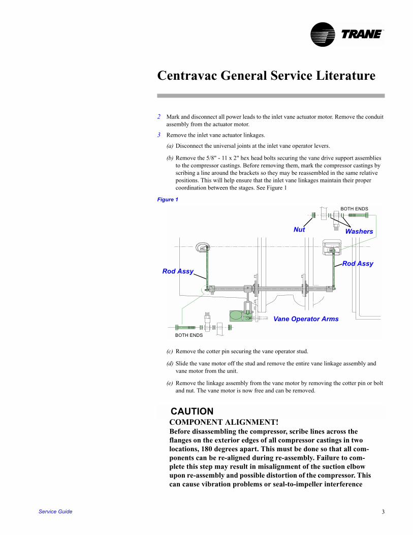
(b) Remove the 5/8" - 11 x 2" hex head bolts securing the vane drive support assemblies to the compressor castings. Before removing them, mark the compressor castings by scribing a line around the brackets so they may be reassembled in the same relative positions. This will help ensure that the inlet vane linkages maintain their proper coordination between the stages. See Figure 1
Figure 1
(c) Remove the cotter pin securing the vane operator stud.
(d) Slide the vane motor off the stud and remove the entire vane linkage assembly and vane motor from the unit.
(e) Remove the linkage assembly from the vane motor by removing the cotter pin or bolt and nut. The vane motor is now free and can be removed.
CAUTIONCOMPONENT ALIGNMENT!Before disassembling the compressor, scribe lines across the flanges on the exterior edges of all compressor castings in two locations, 180 degrees apart. This must be done so that all com-ponents can be re-aligned during re-assembly. Failure to com-plete this step may result in misalignment of the suction elbow upon re-assembly and possible distortion of the compressor. This can cause vibration problems or seal-to-impeller interference
BOTH ENDS
BOTH ENDS
Rod AssyRod Assy
WashersNut
Vane Operator Arms
Service Guide 3
Centravac General Service Literature
TM
and possible damage to the impellers and compressor.
CAUTIONCOMPONENT ALIGNMENT!The following two paragraphs provide instructions to maintain proper component alignment and fit. Make sure the compressor casings are dowelled or scribed and the discharge volute is dow-elled. Failure to maintain proper alignment may result in com-pressor damage. Failure to maintain proper suction elbow fit up can cause vibration problems or seal-to-impeller interference and possible damage to the impellers and compressor.
4 Before proceeding further, check to make sure the discharge volute has dowel pins in the flange at the condenser and the compressor foot where it mounts on the evaporator support bracket. These pins are standard on all newer units and will be required if the discharge volute or entire compressor will be removed from the shells. The alignment of the compressor/motor assembly is determined by the position of the discharge volute. A shift in volute position at either the discharge flange or the compressor foot can change the suction elbow to compressor alignment. Failure to maintain proper suction elbow fit up can cause vibration problems or seal-to-impeller interference and possible damage to the impellers and compressor. Some early vintage CVHE units were built without these two dowel pins. When necessary, dowel pins should be added to the discharge flange and compressor foot. Units ordered for field disassembly (compressor removal) may have the motor, interstage casings and suction cover doweled as well as the discharge flange and foot.For additional information on compressor doweling see General Service Bulletin CVHE-SB-10 (latest revision).
5 If the entire compressor or the volute will need to be removed from the shells, the dowel pins at the discharge flange and foot will have to be removed. First remove the threaded nut on the exposed end of the dowel pin. Then slip washers or a bushing over the pin. Reinstall the nut. As the nut is tightened, the pin will be pulled out of place. The dowel pins allow for precise assembly of the compressor components in their original position.
Note: It is not necessary to dowel all compressor casings for overhauls when properly scribed as detailed above.
IMPORTANT: Make sure the evaporator and condenser inlet and outlet water valves have been closed (no water flow!) and the evaporator and condenser water boxes have been completely drained. Failure to prevent water flow through the unit during repairs could cause severe rusting inside the shells. In humid environments it may be advisable to place a portable light or trouble light (100 -300 Watt) in the evaporator and condenser if necessary to provide enough heat to prevent moisture from condensing in the unit during repairs. In excessively humid environments, consider the use of a nitrogen purge to help prevent corrosion.
6 Remove the economizer to allow for compressor volute clearance.
CTVH-GCO-01-EN4
Centravac General Service Literature
TM
(a) Some CVHE and CVHG units will require cutting the drain line that returns motor cooling liquid to the economizer. Sand the line to remove paint then cut with a tubing cutter. Do not use a hacksaw to cut the line. Always use a tubing cutter to avoid introducing copper chips (debris) into the unit.
(b) On smaller units, a floor jack may be placed under the economizer sump.
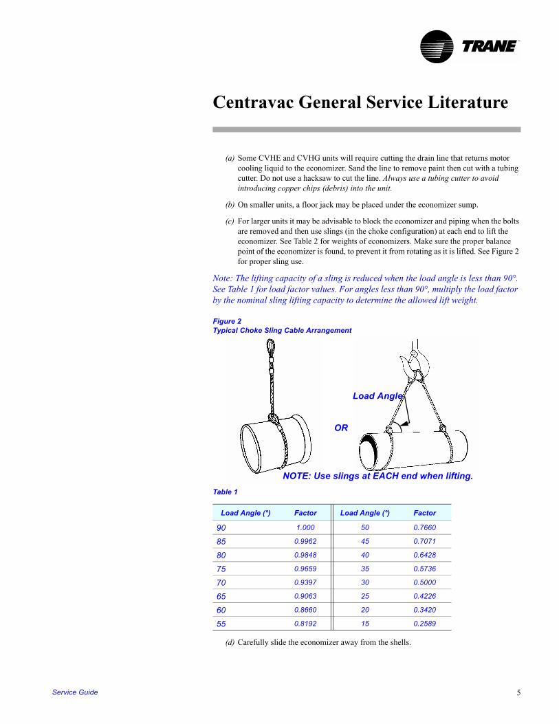
(c) For larger units it may be advisable to block the economizer and piping when the bolts are removed and then use slings (in the choke configuration) at each end to lift the economizer. See Table 2 for weights of economizers. Make sure the proper balance point of the economizer is found, to prevent it from rotating as it is lifted. See Figure 2 for proper sling use.
Note: The lifting capacity of a sling is reduced when the load angle is less than 90°. See Table 1 for load factor values. For angles less than 90°, multiply the load factor by the nominal sling lifting capacity to determine the allowed lift weight.
Figure 2Typical Choke Sling Cable Arrangement
Table 1
(d) Carefully slide the economizer away from the shells.
Load Angle (°) Factor Load Angle (°) Factor
90 1.000 50 0.7660
85 0.9962 45 0.7071
80 0.9848 40 0.6428
75 0.9659 35 0.5736
70 0.9397 30 0.5000
65 0.9063 25 0.4226
60 0.8660 20 0.3420
55 0.8192 15 0.2589
NOTE: Use slings at EACH end when lifting.
OR
Load Angle
Service Guide 5
Centravac General Service Literature
TM
(e) Lightly oil all flanges with compressor oil. Cover all openings with plastic and seal with duct tape to prevent debris from entering the economizer.
(f) Remove the orifice assemblies and mark them properly. Oil the flanges on the condenser liquid line and the evaporator liquid inlet to prevent rusting. Cover the openings with plastic and duct tape to prevent entry of debris.
7 Remove the Suction Elbow.
(a) Remove the bolts from the suction elbow flanges at the evaporator and compressor.
(b) Place a sling in the choke configuration around the suction elbow. Position the sling so the elbow balances properly as it is lifted. Do NOT use the weld nut on the suction elbow for lifting. See Table 2 for the weight of the suction elbow.
(c) Clean and lightly oil the suction elbow flanges to prevent rusting and place the elbow on wooden blocks to protect the face of flange. Remove the o-ring, then thoroughly clean the groove in the flange on the evaporator. Lightly oil the flange on the evaporator. Cover the opening with plywood to protect the flange and prevent debris from entering the evaporator during repairs.
IMPORTANT: Mark all components before removing them. Mark the face of components with a description or location (e.g. 1st stage impeller seal) and the top (12 o'clock) mounting position of all seals, impellers, spacers, casings, plates etc. so they may be re-installed in the same position. This will be important in maintaining the proper balance and alignment of the rotating components during re-assembly.
8 Remove the first stage inlet vane assembly.
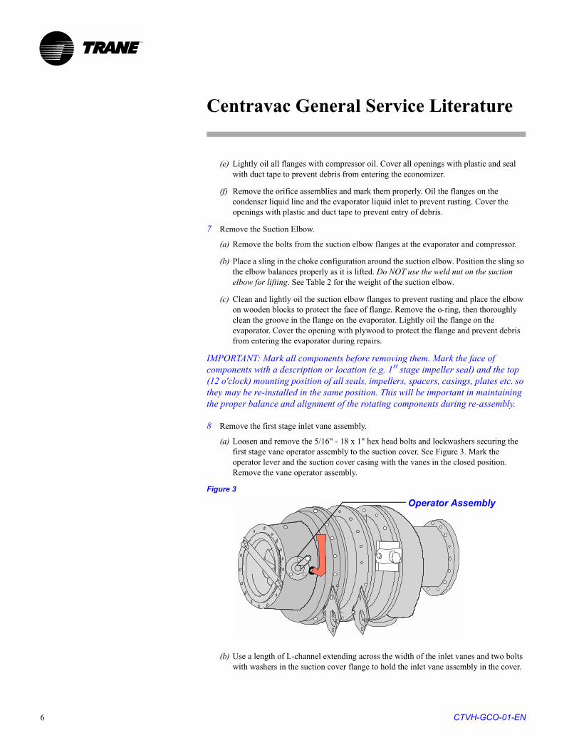
(a) Loosen and remove the 5/16" - 18 x 1" hex head bolts and lockwashers securing the first stage vane operator assembly to the suction cover. See Figure 3. Mark the operator lever and the suction cover casing with the vanes in the closed position. Remove the vane operator assembly.
Figure 3
(b) Use a length of L-channel extending across the width of the inlet vanes and two bolts with washers in the suction cover flange to hold the inlet vane assembly in the cover.
Operator Assembly
CTVH-GCO-01-EN6
Centravac General Service Literature
TM
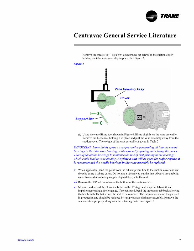
Remove the three 5/16" - 18 x 3/8" countersunk set screws in the suction cover holding the inlet vane assembly in place. See Figure 3.
Figure 4
(c) Using the vane lifting tool shown in Figure 4, lift up slightly on the vane assembly. Remove the L-channel holding it in place and pull the vane assembly away from the suction cover. The weight of the vane assembly is given in Table 2.
IMPORTANT: Immediately spray a rust-preventive penetrating oil into the needle bearings in the inlet vane housing, while manually opening and closing the vanes. Thoroughly oil the bearings to minimize the risk of rust forming in the bearings, which could lead to vane binding. Anytime a unit will be open for major repairs, it is recommended the needle bearings in the vane assembly be replaced.
9 When applicable, sand the paint from the oil sump vent line to the suction cover and cut the pipe using a tubing cutter. Do not use a hacksaw to cut the line. Always use a tubing cutter to avoid introducing copper chips (debris) into the unit.
10 Remove the 1/4" oil drain line at the bottom of the suction cover.
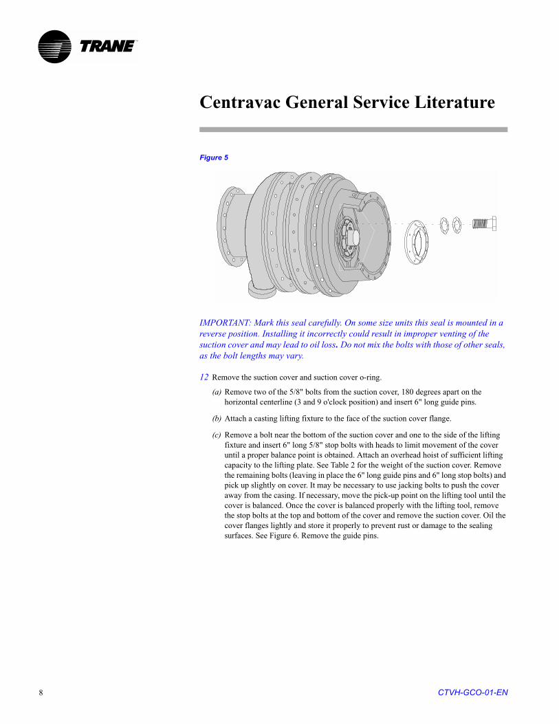
11 Measure and record the clearance between the 1st stage seal impeller labyrinth and impeller nose using a feeler gauge. If so equipped, bend the tabwasher tab back allowing the hex head bolts that secure the seal to be removed. The tabwashers are no longer used in production and should be replaced by ramp washers during re-assembly. Remove the seal and store properly along with the retaining bolts. See Figure 5.
Support Bar
Vane Housing Assy
Cover
Service Guide 7
Centravac General Service Literature
TM
Figure 5
IMPORTANT: Mark this seal carefully. On some size units this seal is mounted in a reverse position. Installing it incorrectly could result in improper venting of the suction cover and may lead to oil loss. Do not mix the bolts with those of other seals, as the bolt lengths may vary.
12 Remove the suction cover and suction cover o-ring.
(a) Remove two of the 5/8" bolts from the suction cover, 180 degrees apart on the horizontal centerline (3 and 9 o'clock position) and insert 6" long guide pins.
(b) Attach a casting lifting fixture to the face of the suction cover flange.
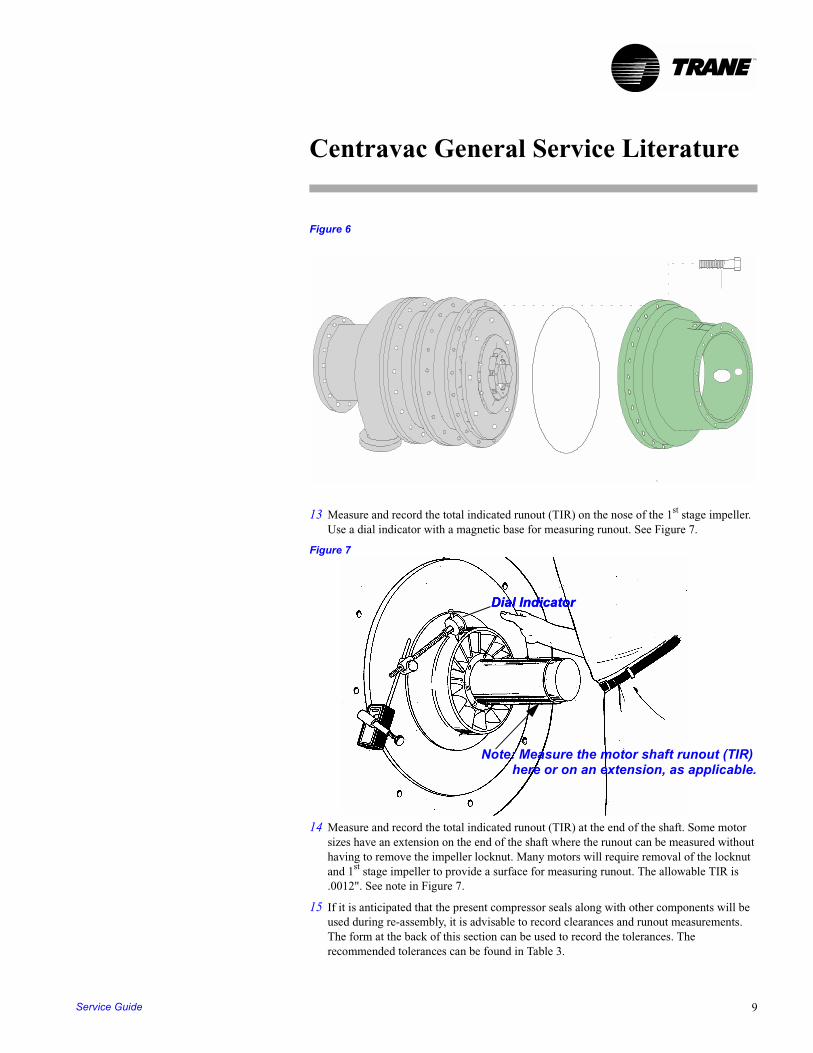
(c) Remove a bolt near the bottom of the suction cover and one to the side of the lifting fixture and insert 6" long 5/8" stop bolts with heads to limit movement of the cover until a proper balance point is obtained. Attach an overhead hoist of sufficient lifting capacity to the lifting plate. See Table 2 for the weight of the suction cover. Remove the remaining bolts (leaving in place the 6" long guide pins and 6" long stop bolts) and pick up slightly on cover. It may be necessary to use jacking bolts to push the cover away from the casing. If necessary, move the pick-up point on the lifting tool until the cover is balanced. Once the cover is balanced properly with the lifting tool, remove the stop bolts at the top and bottom of the cover and remove the suction cover. Oil the cover flanges lightly and store it properly to prevent rust or damage to the sealing surfaces. See Figure 6. Remove the guide pins.
CTVH-GCO-01-EN8
Centravac General Service Literature
TM
Figure 6
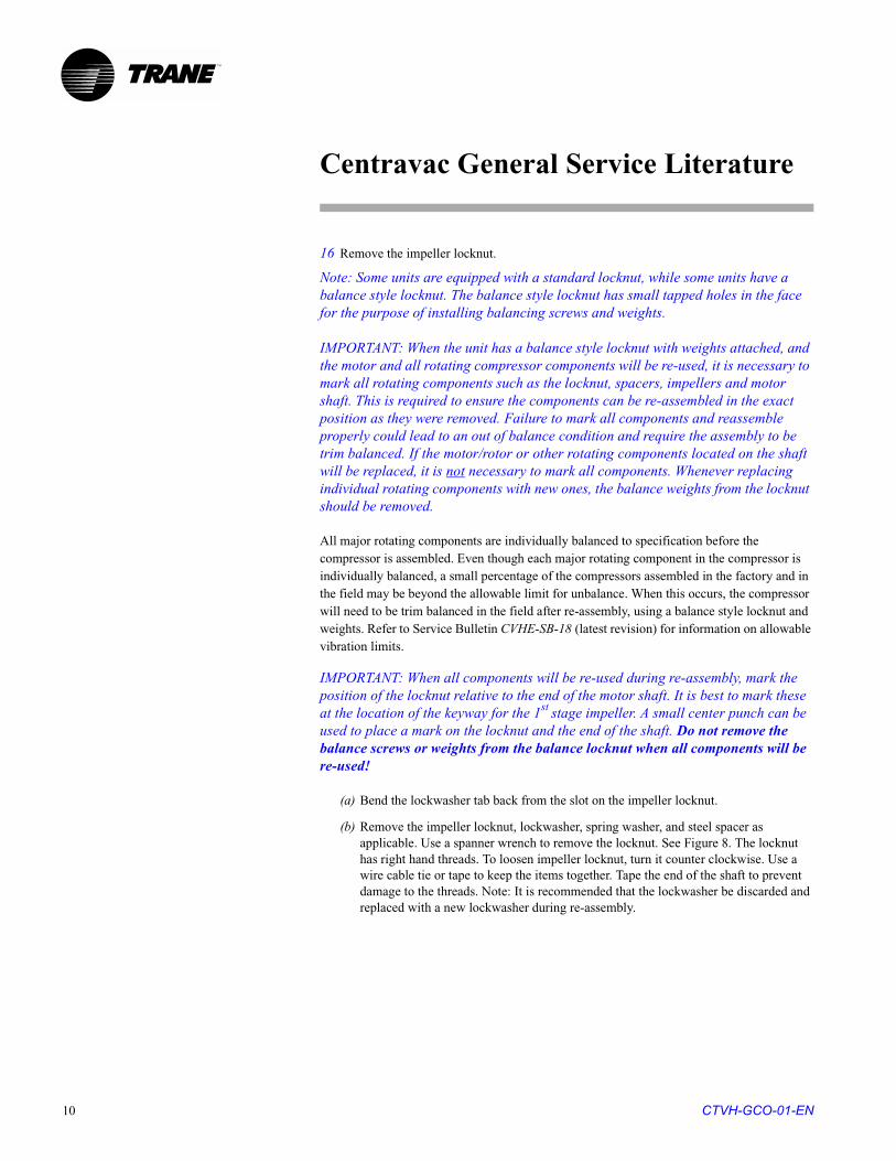
13 Measure and record the total indicated runout (TIR) on the nose of the 1st stage impeller. Use a dial indicator with a magnetic base for measuring runout. See Figure 7.
Figure 7
14 Measure and record the total indicated runout (TIR) at the end of the shaft. Some motor sizes have an extension on the end of the shaft where the runout can be measured without having to remove the impeller locknut. Many motors will require removal of the locknut and 1st stage impeller to provide a surface for measuring runout. The allowable TIR is .0012". See note in Figure 7.
15 If it is anticipated that the present compressor seals along with other components will be used during re-assembly, it is advisable to record clearances and runout measurements. The form at the back of this section can be used to record the tolerances. The recommended tolerances can be found in Table 3.
Dial IndicatorDial Indicator
Note: Measure the motor shaft runout (TIR)here or on an extension, as applicable.
Service Guide 9
Centravac General Service Literature
TM
16 Remove the impeller locknut.
Note: Some units are equipped with a standard locknut, while some units have a balance style locknut. The balance style locknut has small tapped holes in the face for the purpose of installing balancing screws and weights.
IMPORTANT: When the unit has a balance style locknut with weights attached, and the motor and all rotating compressor components will be re-used, it is necessary to mark all rotating components such as the locknut, spacers, impellers and motor shaft. This is required to ensure the components can be re-assembled in the exact position as they were removed. Failure to mark all components and reassemble properly could lead to an out of balance condition and require the assembly to be trim balanced. If the motor/rotor or other rotating components located on the shaft will be replaced, it is not necessary to mark all components. Whenever replacing individual rotating components with new ones, the balance weights from the locknut should be removed.
All major rotating components are individually balanced to specification before the compressor is assembled. Even though each major rotating component in the compressor is individually balanced, a small percentage of the compressors assembled in the factory and in the field may be beyond the allowable limit for unbalance. When this occurs, the compressor will need to be trim balanced in the field after re-assembly, using a balance style locknut and weights. Refer to Service Bulletin CVHE-SB-18 (latest revision) for information on allowable vibration limits.
IMPORTANT: When all components will be re-used during re-assembly, mark the position of the locknut relative to the end of the motor shaft. It is best to mark these at the location of the keyway for the 1st stage impeller. A small center punch can be used to place a mark on the locknut and the end of the shaft. Do not remove the balance screws or weights from the balance locknut when all components will be re-used!
(a) Bend the lockwasher tab back from the slot on the impeller locknut.
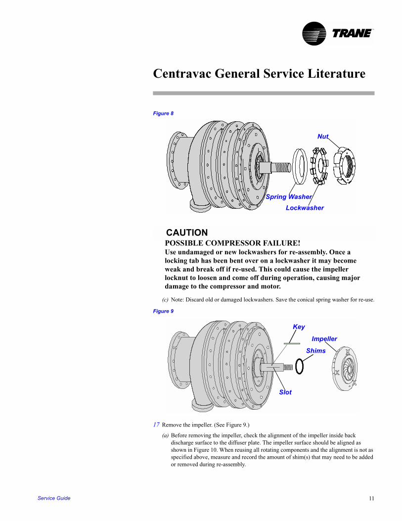
(b) Remove the impeller locknut, lockwasher, spring washer, and steel spacer as applicable. Use a spanner wrench to remove the locknut. See Figure 8. The locknut has right hand threads. To loosen impeller locknut, turn it counter clockwise. Use a wire cable tie or tape to keep the items together. Tape the end of the shaft to prevent damage to the threads. Note: It is recommended that the lockwasher be discarded and replaced with a new lockwasher during re-assembly.
CTVH-GCO-01-EN10
Centravac General Service Literature
TM
Figure 8
CAUTIONPOSSIBLE COMPRESSOR FAILURE!Use undamaged or new lockwashers for re-assembly. Once a locking tab has been bent over on a lockwasher it may become weak and break off if re-used. This could cause the impeller locknut to loosen and come off during operation, causing major damage to the compressor and motor.
(c) Note: Discard old or damaged lockwashers. Save the conical spring washer for re-use.
Figure 9
17 Remove the impeller. (See Figure 9.)
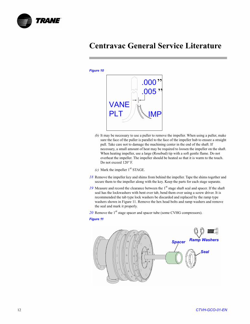
(a) Before removing the impeller, check the alignment of the impeller inside back discharge surface to the diffuser plate. The impeller surface should be aligned as shown in Figure 10. When reusing all rotating components and the alignment is not as specified above, measure and record the amount of shim(s) that may need to be added or removed during re-assembly.
Spring Washer
Lockwasher
Nut
Impeller
Key
Slot
Shims
Service Guide 11
Centravac General Service Literature
TM
Figure 10
(b) It may be necessary to use a puller to remove the impeller. When using a puller, make sure the face of the puller is parallel to the face of the impeller hub to ensure a straight pull. Take care not to damage the machining center in the end of the shaft. If necessary, a small amount of heat may be required to loosen the impeller on the shaft. When heating impeller, use a large (Rosebud) tip with a soft gentle flame. Do not overheat the impeller. The impeller should be heated so that it is warm to the touch. Do not exceed 120° F.
(c) Mark the impeller 1st STAGE.
18 Remove the impeller key and shims from behind the impeller. Tape the shims together and secure them to the impeller along with the key. Keep the parts for each stage separate.
19 Measure and record the clearance between the 1st stage shaft seal and spacer. If the shaft seal has the lockwashers with bent over tab, bend them over using a screw driver. It is recommended the tab type lock washers be discarded and replaced by the ramp type washers shown in Figure 11. Remove the hex head bolts and ramp washers and remove the seal and mark it properly.
20 Remove the 1st stage spacer and spacer tube (some CVHG compressors).
Figure 11
VANEPLT IMP
.000
.005
““
Spacer Ramp Washers
Seal
CTVH-GCO-01-EN12
Centravac General Service Literature
TM
(a) Mark the spacer and spacer tube with its position on the shaft with the first stage impeller keyway at the 12 o’clock position. The shaft spacer has tapped pull-off holes that can be used to pull the spacer if needed. Using the pull-off holes may be required on units where corrosion has occurred due to leaks and moisture or other causes.
(b) Mark the spacer and spacer tube for TOP and 1st STAGE.
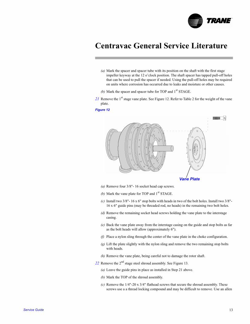
21 Remove the 1st stage vane plate. See Figure 12. Refer to Table 2 for the weight of the vane plate.
Figure 12
(a) Remove four 3/8"- 16 socket head cap screws.
(b) Mark the vane plate for TOP and 1st STAGE.
(c) Install two 3/8"- 16 x 6" stop bolts with heads in two of the bolt holes. Install two 3/8"- 16 x 6" guide pins (may be threaded rod, no heads) in the remaining two bolt holes.
(d) Remove the remaining socket head screws holding the vane plate to the interstage casing.
(e) Back the vane plate away from the interstage casing on the guide and stop bolts as far as the bolt heads will allow (approximately 6").
(f) Place a nylon sling through the center of the vane plate in the choke configuration.
(g) Lift the plate slightly with the nylon sling and remove the two remaining stop bolts with heads.
(h) Remove the vane plate, being careful not to damage the rotor shaft.
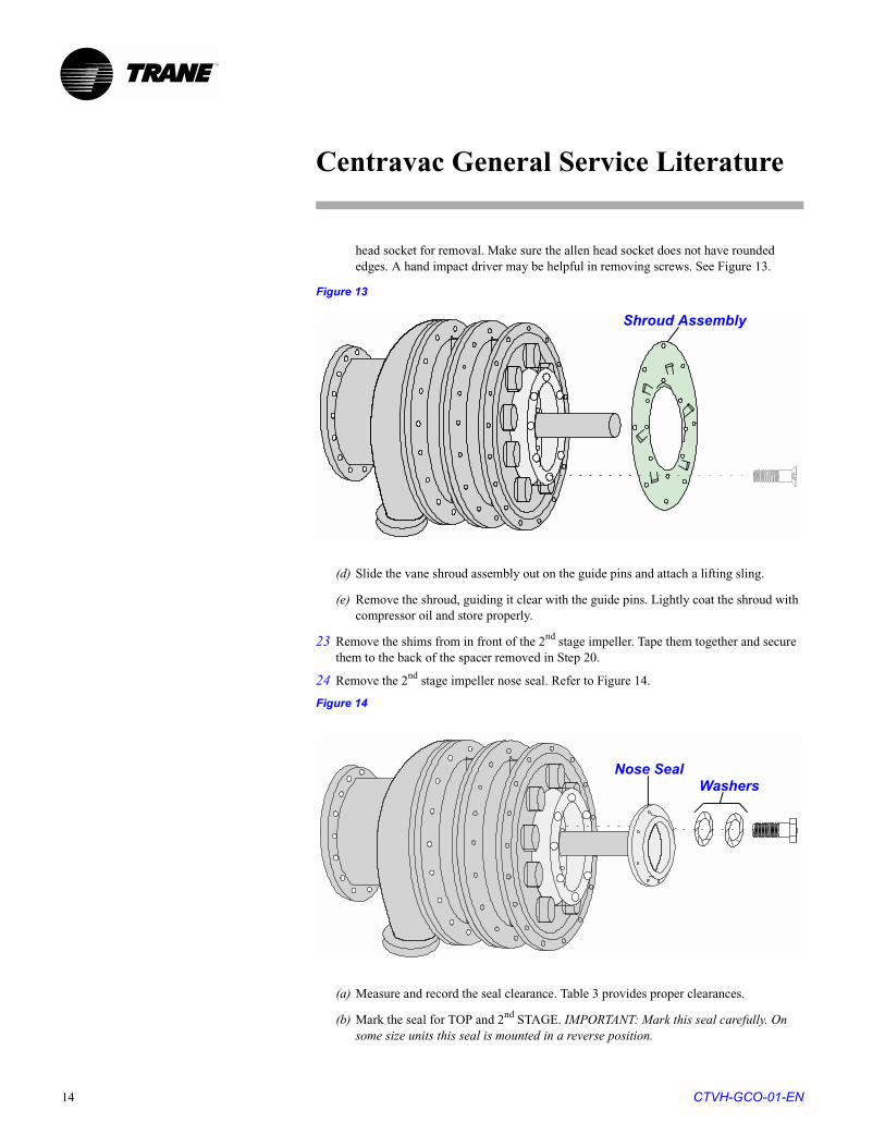
22 Remove the 2nd stage steel shroud assembly. See Figure 13.
(a) Leave the guide pins in place as installed in Step 21 above.
(b) Mark the TOP of the shroud assembly.
(c) Remove the 1/4"-20 x 3/4" flathead screws that secure the shroud assembly. These screws use a a thread locking compound and may be difficult to remove. Use an allen
Vane Plate
Service Guide 13
Centravac General Service Literature
TM
head socket for removal. Make sure the allen head socket does not have rounded edges. A hand impact driver may be helpful in removing screws. See Figure 13.
Figure 13
(d) Slide the vane shroud assembly out on the guide pins and attach a lifting sling.
(e) Remove the shroud, guiding it clear with the guide pins. Lightly coat the shroud with compressor oil and store properly.
23 Remove the shims from in front of the 2nd stage impeller. Tape them together and secure them to the back of the spacer removed in Step 20.
24 Remove the 2nd stage impeller nose seal. Refer to Figure 14.
Figure 14
(a) Measure and record the seal clearance. Table 3 provides proper clearances.
(b) Mark the seal for TOP and 2nd STAGE. IMPORTANT: Mark this seal carefully. On some size units this seal is mounted in a reverse position.
Shroud Assembly
Nose SealWashers
CTVH-GCO-01-EN14
Centravac General Service Literature
TM
(c) Remove the 3/8” - 16 x 1” hex head screws and tab or ramp washers.
(d) Remove the seal. See Figure 14.
25 Measure and record the total indicated runout (TIR) on the nose of the 2nd stage impeller.
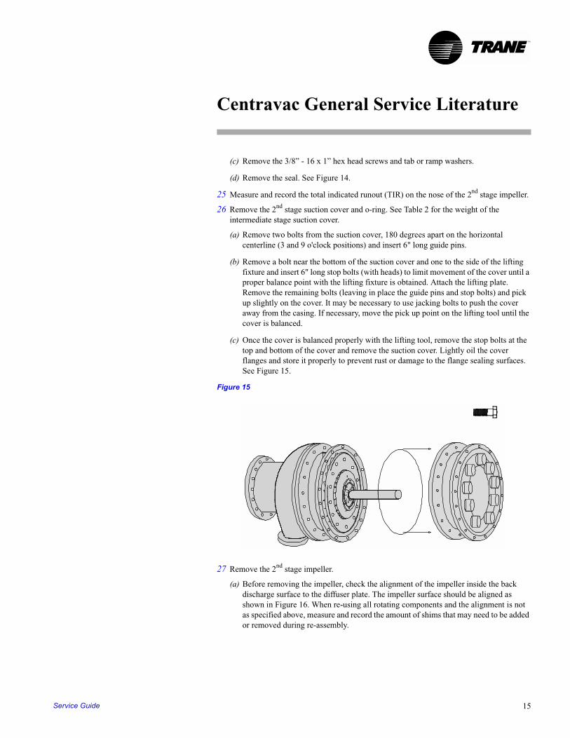
26 Remove the 2nd stage suction cover and o-ring. See Table 2 for the weight of the intermediate stage suction cover.
(a) Remove two bolts from the suction cover, 180 degrees apart on the horizontal centerline (3 and 9 o'clock positions) and insert 6" long guide pins.
(b) Remove a bolt near the bottom of the suction cover and one to the side of the lifting fixture and insert 6" long stop bolts (with heads) to limit movement of the cover until a proper balance point with the lifting fixture is obtained. Attach the lifting plate. Remove the remaining bolts (leaving in place the guide pins and stop bolts) and pick up slightly on the cover. It may be necessary to use jacking bolts to push the cover away from the casing. If necessary, move the pick up point on the lifting tool until the cover is balanced.
(c) Once the cover is balanced properly with the lifting tool, remove the stop bolts at the top and bottom of the cover and remove the suction cover. Lightly oil the cover flanges and store it properly to prevent rust or damage to the flange sealing surfaces. See Figure 15.
Figure 15
27 Remove the 2nd stage impeller.
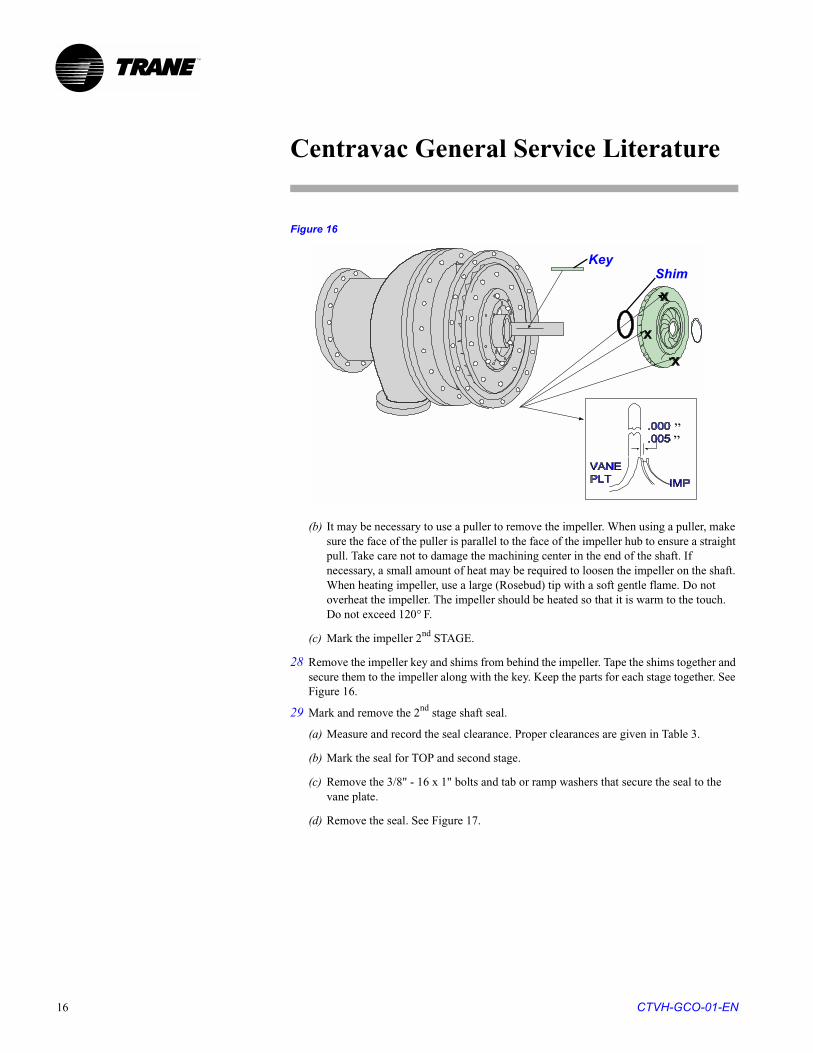
(a) Before removing the impeller, check the alignment of the impeller inside the back discharge surface to the diffuser plate. The impeller surface should be aligned as shown in Figure 16. When re-using all rotating components and the alignment is not as specified above, measure and record the amount of shims that may need to be added or removed during re-assembly.
Service Guide 15
Centravac General Service Literature
TM
Figure 16
(b) It may be necessary to use a puller to remove the impeller. When using a puller, make sure the face of the puller is parallel to the face of the impeller hub to ensure a straight pull. Take care not to damage the machining center in the end of the shaft. If necessary, a small amount of heat may be required to loosen the impeller on the shaft. When heating impeller, use a large (Rosebud) tip with a soft gentle flame. Do not overheat the impeller. The impeller should be heated so that it is warm to the touch. Do not exceed 120° F.
(c) Mark the impeller 2nd STAGE.
28 Remove the impeller key and shims from behind the impeller. Tape the shims together and secure them to the impeller along with the key. Keep the parts for each stage together. See Figure 16.
29 Mark and remove the 2nd stage shaft seal.
(a) Measure and record the seal clearance. Proper clearances are given in Table 3.
(b) Mark the seal for TOP and second stage.
(c) Remove the 3/8" - 16 x 1" bolts and tab or ramp washers that secure the seal to the vane plate.
(d) Remove the seal. See Figure 17.
KeyShim
““
CTVH-GCO-01-EN16

Centravac General Service Literature
TM
Figure 17
30 Remove the 2nd stage shaft spacer.
(a) Mark spacer position on the shaft with the 1st stage impeller keyway at the 12 o’clock position.
(b) Mark the seal for TOP and 2nd STAGE.
31 Remove the aluminum vane plate. See Figure 18. Refer to Table 2 for the weight of the vane plate.
Figure 18
(a) Remove four 3/8"-16 socket head screws.
(b) Mark the vane plate for TOP and 2nd STAGE.
(c) Install two 3/8"-16 x 6” stop bolts with heads in two of the bolt holes. See Figure 12. Install two 3/8"-16 x 6" guide pins (can be threaded rod, no heads) in the remaining two bolt holes.
(d) Remove the remaining socket head screws holding the vane plate to the interstage casing.
Spacer
Inner Seal
Ramp Washers
Service Guide 17
Centravac General Service Literature
TM
(e) Back the vane plate away from the interstage casing on the bolts as far as the bolt heads will allow.
(f) Place a nylon sling through the center of the vane plate in the choke configuration.
(g) Lift the plate slightly with the nylon sling until the two stop bolts (with heads) can be removed.
(h) Remove the vane plate, being careful not to damage the rotor shaft.
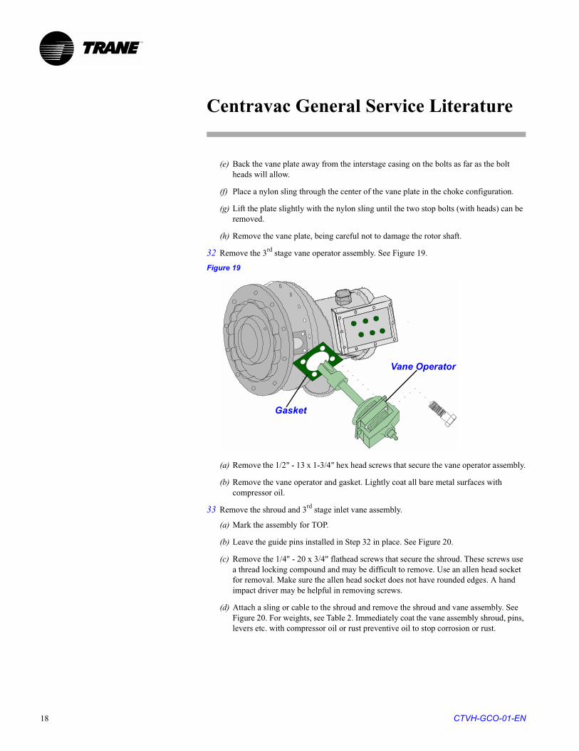
32 Remove the 3rd stage vane operator assembly. See Figure 19.
Figure 19
(a) Remove the 1/2" - 13 x 1-3/4" hex head screws that secure the vane operator assembly.
(b) Remove the vane operator and gasket. Lightly coat all bare metal surfaces with compressor oil.
33 Remove the shroud and 3rd stage inlet vane assembly.
(a) Mark the assembly for TOP.
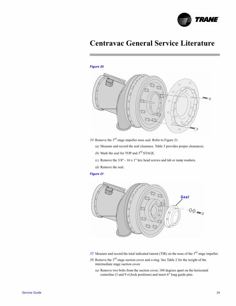
(b) Leave the guide pins installed in Step 32 in place. See Figure 20.
(c) Remove the 1/4" - 20 x 3/4" flathead screws that secure the shroud. These screws use a thread locking compound and may be difficult to remove. Use an allen head socket for removal. Make sure the allen head socket does not have rounded edges. A hand impact driver may be helpful in removing screws.
(d) Attach a sling or cable to the shroud and remove the shroud and vane assembly. See Figure 20. For weights, see Table 2. Immediately coat the vane assembly shroud, pins, levers etc. with compressor oil or rust preventive oil to stop corrosion or rust.
Gasket
Vane Operator
CTVH-GCO-01-EN18
Centravac General Service Literature
TM
Figure 20
34 Remove the 3rd stage impeller nose seal. Refer to Figure 21.
(a) Measure and record the seal clearance. Table 3 provides proper clearances.
(b) Mark the seal for TOP and 3rd STAGE.
(c) Remove the 3/8" - 16 x 1" hex head screws and tab or ramp washers.
(d) Remove the seal.
Figure 21
35 Measure and record the total indicated runout (TIR) on the nose of the 3rd stage impeller.
36 Remove the 3rd stage suction cover and o-ring. See Table 2 for the weight of the intermediate stage suction cover.
(a) Remove two bolts from the suction cover, 180 degrees apart on the horizontal centerline (3 and 9 o'clock positions) and insert 6" long guide pins.
Seal
Service Guide 19
Centravac General Service Literature
TM
(b) Remove a bolt near the bottom of the suction cover and one to the side of the lifting fixture and insert 6" long stop bolts (with heads) to limit movement of the cover until a proper balance point with the lifting fixture is obtained. Attach the lifting plate. Remove the remaining bolts (leaving in place the guide pins and stop bolts) and pick up slightly on the cover. It may be necessary to use jacking bolts to push the cover away from the casing. If necessary, move the pick-up point on the lifting tool until the cover is balanced.
(c) Once the cover is balanced properly with the lifting tool, remove the stop bolts at the top and bottom of the cover and remove the suction cover. Lightly oil the cover flanges and store it properly to prevent rust or damage to the flange sealing surfaces. See Figure 22.
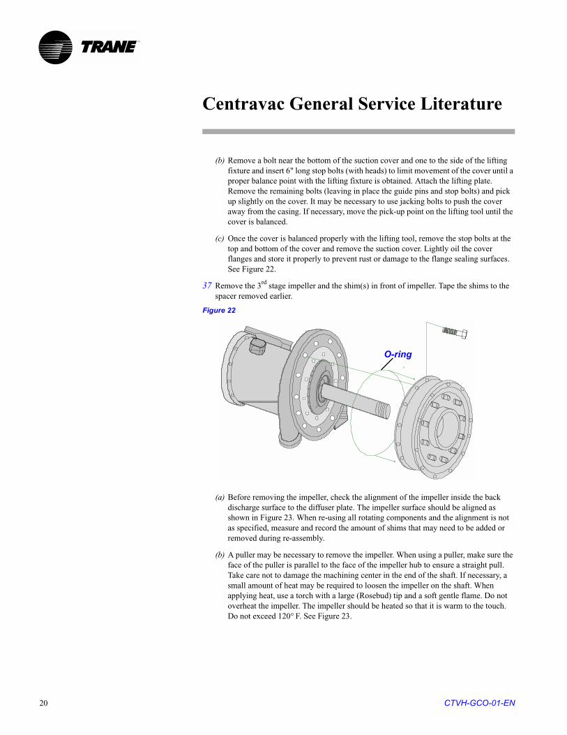
37 Remove the 3rd stage impeller and the shim(s) in front of impeller. Tape the shims to the spacer removed earlier.
Figure 22
(a) Before removing the impeller, check the alignment of the impeller inside the back discharge surface to the diffuser plate. The impeller surface should be aligned as shown in Figure 23. When re-using all rotating components and the alignment is not as specified, measure and record the amount of shims that may need to be added or removed during re-assembly.
(b) A puller may be necessary to remove the impeller. When using a puller, make sure the face of the puller is parallel to the face of the impeller hub to ensure a straight pull. Take care not to damage the machining center in the end of the shaft. If necessary, a small amount of heat may be required to loosen the impeller on the shaft. When applying heat, use a torch with a large (Rosebud) tip and a soft gentle flame. Do not overheat the impeller. The impeller should be heated so that it is warm to the touch. Do not exceed 120° F. See Figure 23.
O-ring
CTVH-GCO-01-EN20
Centravac General Service Literature
TM
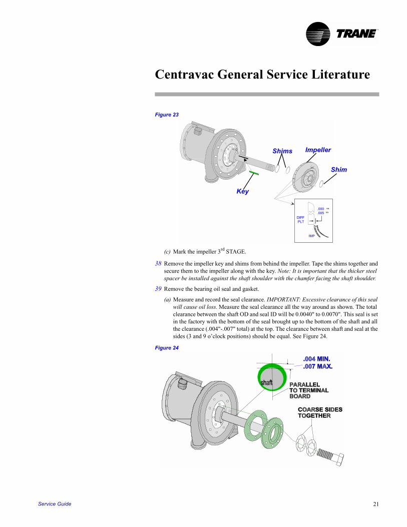
Figure 23
(c) Mark the impeller 3rd STAGE.
38 Remove the impeller key and shims from behind the impeller. Tape the shims together and secure them to the impeller along with the key. Note: It is important that the thicker steel spacer be installed against the shaft shoulder with the chamfer facing the shaft shoulder.
39 Remove the bearing oil seal and gasket.
(a) Measure and record the seal clearance. IMPORTANT: Excessive clearance of this seal will cause oil loss. Measure the seal clearance all the way around as shown. The total clearance between the shaft OD and seal ID will be 0.0040" to 0.0070". This seal is set in the factory with the bottom of the seal brought up to the bottom of the shaft and all the clearance (.004"-.007" total) at the top. The clearance between shaft and seal at the sides (3 and 9 o’clock positions) should be equal. See Figure 24.
Figure 24
DIFF PLT
IMP
.000
.005
X
XX
ImpellerShims
Shim
Key
““
Service Guide 21
Centravac General Service Literature
TM
(b) Mark the seal for TOP. IMPORTANT: The seal has a small oil drain hole in the back which must be correctly aligned during re-assembly. The drain hole must be at the 6 o’clock position.
(c) Remove the hex head screws and tab or ramp washers securing the seal and gasket.
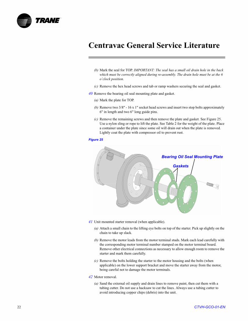
40 Remove the bearing oil seal mounting plate and gasket.
(a) Mark the plate for TOP.
(b) Remove two 3/8" - 16 x 1" socket head screws and insert two stop bolts approximately 6" in length and two 6" long guide pins.
(c) Remove the remaining screws and then remove the plate and gasket. See Figure 25. Use a nylon sling or rope to lift the plate. See Table 2 for the weight of the plate. Place a container under the plate since some oil will drain out when the plate is removed. Lightly coat the plate with compressor oil to prevent rust.
Figure 25
41 Unit mounted starter removal (when applicable).
(a) Attach a small chain to the lifting eye bolts on top of the starter. Pick up slightly on the chain to take up slack.
(b) Remove the motor leads from the motor terminal studs. Mark each lead carefully with the corresponding motor terminal number stamped on the motor terminal board. Remove other electrical connections as necessary to allow enough room to remove the starter and mark them carefully.
(c) Remove the bolts holding the starter to the motor housing and the bolts (when applicable) on the lower support bracket and move the starter away from the motor, being careful not to damage the motor terminals.
42 Motor removal.
(a) Sand the external oil supply and drain lines to remove paint, then cut them with a tubing cutter. Do not use a hacksaw to cut the lines. Always use a tubing cutter to avoid introducing copper chips (debris) into the unit.
Bearing Oil Seal Mounting Plate
Gaskets
CTVH-GCO-01-EN22
Centravac General Service Literature
TM
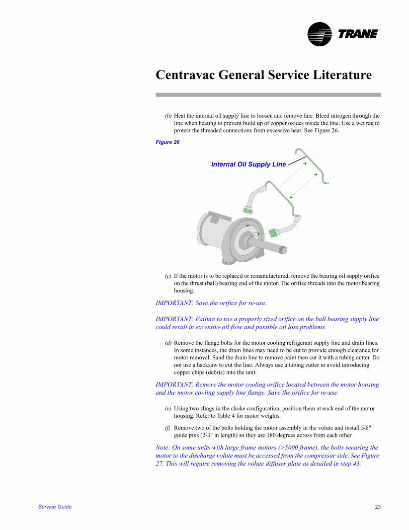
(b) Heat the internal oil supply line to loosen and remove line. Bleed nitrogen through the line when heating to prevent build up of copper oxides inside the line. Use a wet rag to protect the threaded connections from excessive heat. See Figure 26.
Figure 26
(c) If the motor is to be replaced or remanufactured, remove the bearing oil supply orifice on the thrust (ball) bearing end of the motor. The orifice threads into the motor bearing housing.
IMPORTANT: Save the orifice for re-use.
IMPORTANT: Failure to use a properly sized orifice on the ball bearing supply line could result in excessive oil flow and possible oil loss problems.
(d) Remove the flange bolts for the motor cooling refrigerant supply line and drain lines. In some instances, the drain lines may need to be cut to provide enough clearance for motor removal. Sand the drain line to remove paint then cut it with a tubing cutter. Do not use a hacksaw to cut the line. Always use a tubing cutter to avoid introducing copper chips (debris) into the unit.
IMPORTANT: Remove the motor cooling orifice located between the motor housing and the motor cooling supply line flange. Save the orifice for re-use.
(e) Using two slings in the choke configuration, position them at each end of the motor housing. Refer to Table 4 for motor weights.
(f) Remove two of the bolts holding the motor assembly in the volute and install 5/8" guide pins (2-3" in length) so they are 180 degrees across from each other.
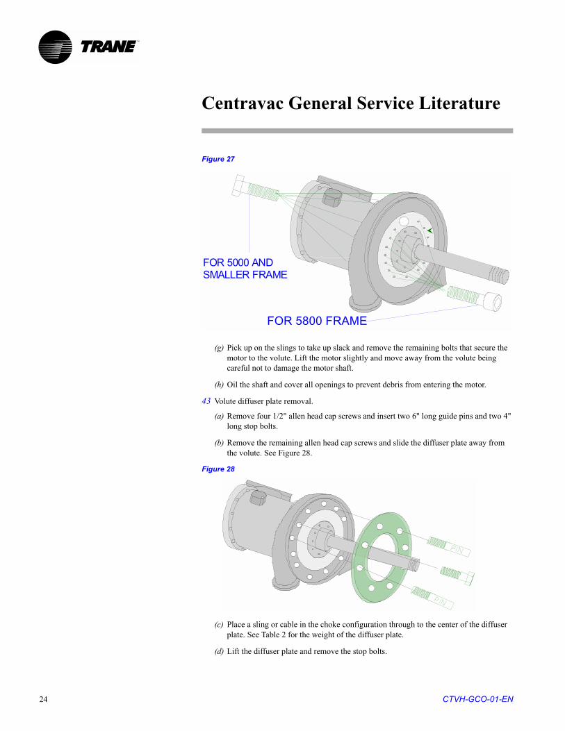
Note: On some units with large frame motors (>5000 frame), the bolts securing the motor to the discharge volute must be accessed from the compressor side. See Figure 27. This will require removing the volute diffuser plate as detailed in step 43.
Internal Oil Supply Line
Service Guide 23
Centravac General Service Literature
TM
Figure 27
(g) Pick up on the slings to take up slack and remove the remaining bolts that secure the motor to the volute. Lift the motor slightly and move away from the volute being careful not to damage the motor shaft.
(h) Oil the shaft and cover all openings to prevent debris from entering the motor.
43 Volute diffuser plate removal.
(a) Remove four 1/2" allen head cap screws and insert two 6" long guide pins and two 4" long stop bolts.
(b) Remove the remaining allen head cap screws and slide the diffuser plate away from the volute. See Figure 28.
Figure 28
(c) Place a sling or cable in the choke configuration through to the center of the diffuser plate. See Table 2 for the weight of the diffuser plate.
(d) Lift the diffuser plate and remove the stop bolts.
FOR 5000 AND SMALLER FRAME
FOR 5800 FRAME
CTVH-GCO-01-EN24
Centravac General Service Literature
TM
(e) Slide the diffuser plate away from the volute. Oil the diffuser to prevent rusting.
44 Discharge volute removal.
(a) Remove the dowel pins on the discharge flange at the condenser and on the foot of the volute. First remove the threaded nut on the exposed end of the dowel pin. Then slip washers or a bushing over the pin and reinstall the nut. As the nut is tightened, the pin will be pulled out of place. The dowel pins allow for precise assembly of the compressor components in their original position.
(b) Place a sling in the choke configuration through the center of the volute. Take up the slack in the sling.
(c) Remove the bolts at the discharge flange and the compressor foot and then lift the volute. See Table 2 for volute weights.
(d) Clean and oil the discharge flange on the condenser and cover the opening to prevent entry of debris
Inspect all components for damage or excessive wear. Do not re-assemble the compressor using faulty components. Clean each component and apply a light coat of compressor oil to protect it from moisture and corrosion (especially o-ring and gasket surfaces).
Note: Refer to Centravac Literature Section CTVH-GCO-02 for the compressor re-assembly procedures.
Service Guide 25
Centravac G
eneral Service Literature C
TV
H-G
CO
-01-EN26
TC
Steel Volute
Diffuser Plate
Discharge Volute
Complete Compressor
Including Motor
162 800 5665
162 793 6880
162 910 7300
232 1110 9175
346 1608 11125
356 1418
309 1430
309 1820
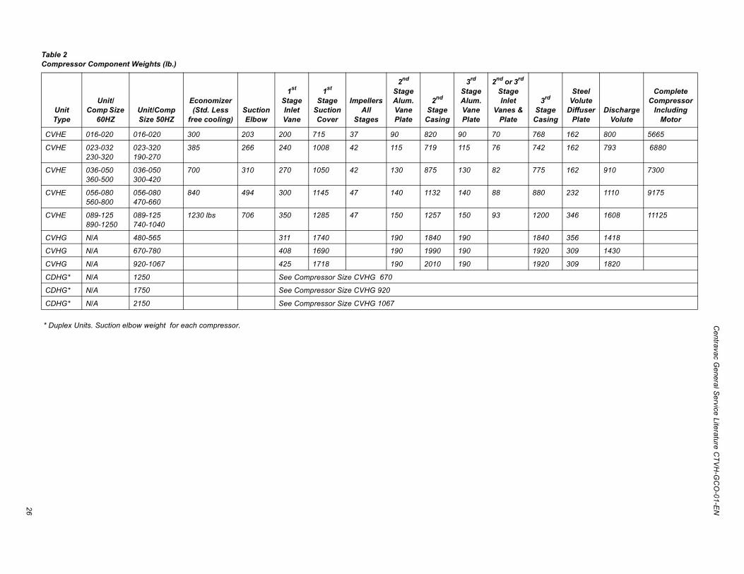
able 2ompressor Component Weights (lb.)
* Duplex Units. Suction elbow weight for each compressor.
Unit Type
Unit/ Comp Size
60HZUnit/Comp Size 50HZ
Economizer (Std. Less
free cooling)Suction Elbow
1st Stage Inlet Vane
1st Stage
Suction Cover
Impellers All
Stages
2nd
Stage Alum. Vane Plate
2nd
Stage Casing
3rd
Stage Alum. Vane Plate
2nd or 3rd
Stage Inlet
Vanes & Plate
3rd
StageCasing
CVHE 016-020 016-020 300 203 200 715 37 90 820 90 70 768
CVHE 023-032230-320
023-320190-270
385 266 240 1008 42 115 719 115 76 742
CVHE 036-050360-500
036-050300-420
700 310 270 1050 42 130 875 130 82 775
CVHE 056-080560-800
056-080470-660
840 494 300 1145 47 140 1132 140 88 880
CVHE 089-125890-1250
089-125740-1040
1230 lbs 706 350 1285 47 150 1257 150 93 1200
CVHG N/A 480-565 311 1740 190 1840 190 1840
CVHG N/A 670-780 408 1690 190 1990 190 1920
CVHG N/A 920-1067 425 1718 190 2010 190 1920
CDHG* N/A 1250 See Compressor Size CVHG 670
CDHG* N/A 1750 See Compressor Size CVHG 920
CDHG* N/A 2150 See Compressor Size CVHG 1067
Centravac G
eneral Service Literature C
TV
H-G
CO
-01-EN27
Interstage Seal to Shaft Spacer
Bearing Oil Seal to Shaft+ (in.)
Radial Clearance See Note +
.0180-.0240 .0040-.0070
.0180-.0240 .0040-.0070
.0180-.0240 .0040-.0070
.0180-.0240 .0040-.0070
.0180-.0240 .0040-.0070
.0180-.0240 .0040-.0070
.0180-.0240 .0040-.0070
.0180-.0240 .0040-.0070
.0180-.0240 .0040-.0070
.0180-.0240 .0040-.0070
.0180-.0240 .0040-.0070
.0180-.0240 .0040-.0070
.0180-.0240 .0040-.0070
.0180-.0240 .0040-.0070
.0180-.0240 .0040-.0070
.0180-.0240 .0040-.0070
.0180-.0240 .0040-.0070
.0180-.0240 .0040-.0070
.0180-.0240 .0040-.0070
.0180-.0240 .0040-.0070
.0180-.0240 .0040-.0070
.0180-.0240 .0040-.0070
.0180-.0240 .0040-.0070
.0180-.0240 .0040-.0070
.0180-.0240 .0040-.0070
.0180-.0240 .0040-.0070
.0100-.0160 .0040-.0070
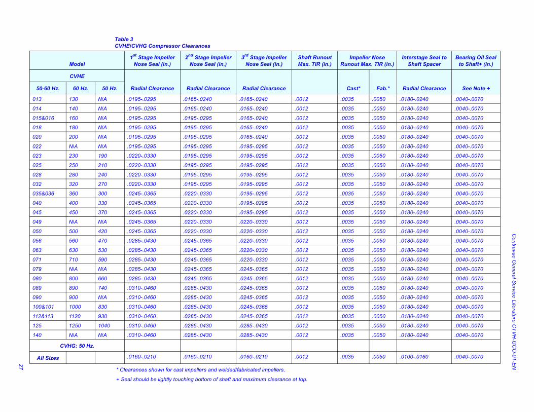
Table 3CVHE/CVHG Compressor Clearances
* Clearances shown for cast impellers and welded/fabricated impellers.
+ Seal should be lightly touching bottom of shaft and maximum clearance at top.
Model1st Stage Impeller
Nose Seal (in.)2nd Stage Impeller
Nose Seal (in.)3rd Stage Impeller
Nose Seal (in.)Shaft Runout Max. TIR (in.)
Impeller Nose Runout Max. TIR (in.)
CVHE
Radial Clearance Radial Clearance Radial Clearance Cast* Fab.*50-60 Hz. 60 Hz. 50 Hz.
013 130 N/A .0195-.0295 .0165-.0240 .0165-.0240 .0012 .0035 .0050
014 140 N/A .0195-.0295 .0165-.0240 .0165-.0240 .0012 .0035 .0050
015&016 160 N/A .0195-.0295 .0195-.0295 .0165-.0240 .0012 .0035 .0050
018 180 N/A .0195-.0295 .0195-.0295 .0165-.0240 .0012 .0035 .0050
020 200 N/A .0195-.0295 .0195-.0295 .0165-.0240 .0012 .0035 .0050
022 N/A N/A .0195-.0295 .0195-.0295 .0195-.0295 .0012 .0035 .0050
023 230 190 .0220-.0330 .0195-.0295 .0195-.0295 .0012 .0035 .0050
025 250 210 .0220-.0330 .0195-.0295 .0195-.0295 .0012 .0035 .0050
028 280 240 .0220-.0330 .0195-.0295 .0195-.0295 .0012 .0035 .0050
032 320 270 .0220-.0330 .0195-.0295 .0195-.0295 .0012 .0035 .0050
035&036 360 300 .0245-.0365 .0220-.0330 .0195-.0295 .0012 .0035 .0050
040 400 330 .0245-.0365 .0220-.0330 .0195-.0295 .0012 .0035 .0050
045 450 370 .0245-.0365 .0220-.0330 .0195-.0295 .0012 .0035 .0050
049 N/A N/A .0245-.0365 .0220-.0330 .0220-.0330 .0012 .0035 .0050
050 500 420 .0245-.0365 .0220-.0330 .0220-.0330 .0012 .0035 .0050
056 560 470 .0285-.0430 .0245-.0365 .0220-.0330 .0012 .0035 .0050
063 630 530 .0285-.0430 .0245-.0365 .0220-.0330 .0012 .0035 .0050
071 710 590 .0285-.0430 .0245-.0365 .0220-.0330 .0012 .0035 .0050
079 N/A N/A .0285-.0430 .0245-.0365 .0245-.0365 .0012 .0035 .0050
080 800 660 .0285-.0430 .0245-.0365 .0245-.0365 .0012 .0035 .0050
089 890 740 .0310-.0460 .0285-.0430 .0245-.0365 .0012 .0035 .0050
090 900 N/A .0310-.0460 .0285-.0430 .0245-.0365 .0012 .0035 .0050
100&101 1000 830 .0310-.0460 .0285-.0430 .0245-.0365 .0012 .0035 .0050
112&113 1120 930 .0310-.0460 .0285-.0430 .0245-.0365 .0012 .0035 .0050
125 1250 1040 .0310-.0460 .0285-.0430 .0285-.0430 .0012 .0035 .0050
140 N/A N/A .0310-.0460 .0285-.0430 .0285-.0430 .0012 .0035 .0050
CVHG: 50 Hz.
All Sizes .0160-.0210 .0160-.0210 .0160-.0210 .0012 .0035 .0050
Centravac General Service Literature
TM
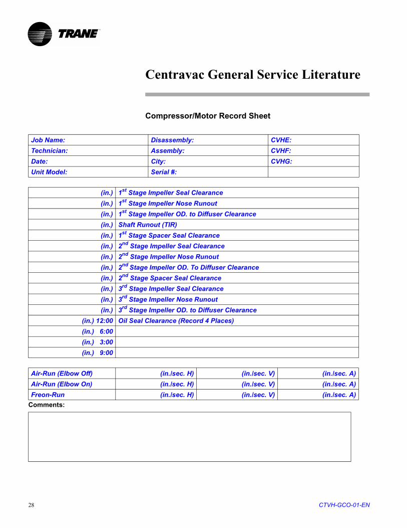
Compressor/Motor Record Sheet
Comments:
Job Name: Disassembly: CVHE:
Technician: Assembly: CVHF:
Date: City: CVHG:
Unit Model: Serial #:
(in.) 1st Stage Impeller Seal Clearance
(in.) 1st Stage Impeller Nose Runout
(in.) 1st Stage Impeller OD. to Diffuser Clearance
(in.) Shaft Runout (TIR)
(in.) 1st Stage Spacer Seal Clearance
(in.) 2nd Stage Impeller Seal Clearance
(in.) 2nd Stage Impeller Nose Runout
(in.) 2nd Stage Impeller OD. To Diffuser Clearance
(in.) 2nd Stage Spacer Seal Clearance
(in.) 3rd Stage Impeller Seal Clearance
(in.) 3rd Stage Impeller Nose Runout
(in.) 3rd Stage Impeller OD. to Diffuser Clearance
(in.) 12:00 Oil Seal Clearance (Record 4 Places)
(in.) 6:00
(in.) 3:00
(in.) 9:00
Air-Run (Elbow Off) (in./sec. H) (in./sec. V) (in./sec. A)
Air-Run (Elbow On) (in./sec. H) (in./sec. V) (in./sec. A)
Freon-Run (in./sec. H) (in./sec. V) (in./sec. A)
CTVH-GCO-01-EN28
Centravac General Service Literature
TM
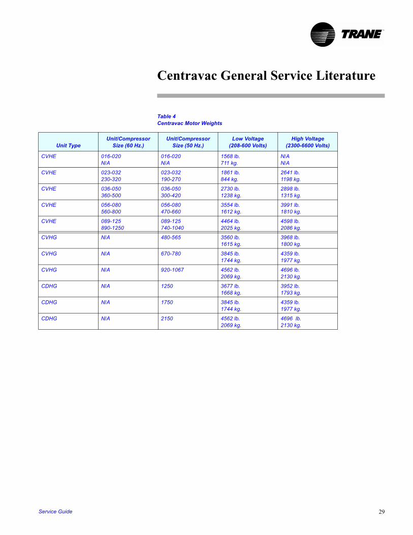
Table 4Centravac Motor Weights
Unit TypeUnit/Compressor
Size (60 Hz.)Unit/Compressor
Size (50 Hz.)Low Voltage
(208-600 Volts)High Voltage
(2300-6600 Volts)
CVHE 016-020N/A
016-020N/A
1568 lb. 711 kg.
N/AN/A
CVHE 023-032230-320
023-032190-270
1861 lb.844 kg.
2641 lb.1198 kg.
CVHE 036-050360-500
036-050300-420
2730 lb.1238 kg.
2898 lb.1315 kg.
CVHE 056-080560-800
056-080470-660
3554 lb.1612 kg.
3991 lb.1810 kg.
CVHE 089-125890-1250
089-125740-1040
4464 lb.2025 kg.
4598 lb.2086 kg.
CVHG N/A 480-565 3560 lb.1615 kg.
3968 lb.1800 kg.
CVHG N/A 670-780 3845 lb.1744 kg.
4359 lb.1977 kg.
CVHG N/A 920-1067 4562 lb.2069 kg.
4696 lb.2130 kg.
CDHG N/A 1250 3677 lb.1668 kg.
3952 lb.1793 kg.
CDHG N/A 1750 3845 lb.1744 kg.
4359 lb.1977 kg.
CDHG N/A 2150 4562 lb.2069 kg.
4696 lb.2130 kg.
Service Guide 29
Centravac General Service Literature
TM
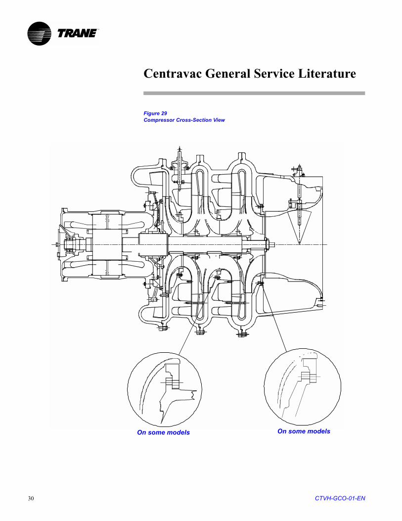
Figure 29Compressor Cross-Section View
On some models On some models
CTVH-GCO-01-EN30
![Trane CVHE,F,G-SB-33C[1]](https://static.fdocuments.in/doc/165x107/54f8233f4a79590a4e8b497c/trane-cvhefg-sb-33c1.jpg)