CUTTHROAT FLUME INTO A DISCHARGE MEASURING INSTRUMENTpublications.iwmi.org/pdf/H019735.pdf ·...
66
REPORT NO. T-5 CONVERTING A FABRICATED CUTTHROAT FLUME INTO A DISCHARGE MEASURING INSTRUMENT 11m' Cj T .10 S .» (2- l-j /873.5 ........ _ ..... "'. .. _. - ... Prepared by Rubina Siddiqui Bakhshal Lashari Gaylord V. Skogerboe November 1996 Hyderabad Office PAKISTAN NATIONAL PROGRAM INTERNATIONAL IRRIGATION MANAGEMENT INSTITUTE H 19135 c f
-
Upload
hoangtuong -
Category
Documents
-
view
214 -
download
0
Transcript of CUTTHROAT FLUME INTO A DISCHARGE MEASURING INSTRUMENTpublications.iwmi.org/pdf/H019735.pdf ·...
REPORT NO. T-5
CONVERTING A FABRICATED
CUTTHROAT FLUME
INTO A DISCHARGE
~ MEASURING INSTRUMENT
11m' 6'~/.1-.1
Cj T .10 S .» (2
l-j /873.5 ........_..... "'. .. .~~ _. - ..._.~
Prepared by
Rubina Siddiqui Bakhshal Lashari
Gaylord V. Skogerboe
November 1996
Hyderabad Office PAKISTAN NATIONAL PROGRAM
INTERNATIONAL IRRIGATION MANAGEMENT INSTITUTE
H 19135 c f
Table of Contents
LIST OF fiGURES ii
LIST OF TABLES iv
GENERAL' DESCRIPTION 1
CHECKING THE FABRICATED FLUME 1 Throat Width . . . . . . . . . . . . . . . . . . . . . . . . . . . . . . . . . . . . . . . . . . . . .. 1 Piezometer Taps " 9 Entrance and Exit Widths 14 Flume Lengths 19 Summary 22
CREATING AN INSTRUMENT 22 Marking Spirit Level Locations on Top of F!ume 23 Checking the Staff Gauges 24
INSTALLATION OF CUTTHROAT FLUME 32 Site Selection 32 Installation to Ensure Free Flow . . . . . . . . . . . . . . . . . . . . . . . . . . . . . .. 33 Installation under Submerged Flow Conditions 36 Selection of Flume Size . . . . . . . . . . . . . . . . . . . . . . . . . . . . . . . . . . . .. 40 Building the Pad 40 Leveling the Installed Flume 42 Sealing the Sides and Underneath the Flume . . . . . . . . . . . . . . . . . . . .. 42
DETERMINING THE DISCHARGE RATE 45 Reading Flow Depths in a Cutthroat Flume . . . . . . . . . . . . . . . . . . . . . .. 45 Correcting the Gauge Readings . . . . . . . . . . . . . . . . . . . . . . . . . . . . . .. 45 Determining the Submergence " 45 Representation of Discharge Ratings 46 Obtaining tile Discharge Rate 51
REFERENCES 54
ANNEXURE 55
Figure 1. Figure 2.
(a)
(b)
Figure 3.
(a) (b)
Figure 4.
(a) (b)
Figure 5. (a) (b)
Figure 6. (a) (b)
Figure 7. (a) (b)
Figure 8. (a)
(b)
Figure 9. (a)
(b)
Figure 10
List of Figures
Definition sketch of a Cutthroat Flume. 2 Measuring the throat width of a Cutthroat 3 Flume using internal calipers. Placement of internal calipers in the throat section. Using vernier calipers to accurately measure the throat width from the internal calipers. Measuring the distance from the throat to the upstream piezometer tap. 11 Establishing the flume centerline. Measuring the perpendicular distance from the flume centerline to the upstream piezometer tap. Measuring the distance from the throat to the downstream piezometer tap. 13 Establishing tile flume centerline. Measuring the perpendicular distance from the flume centerline to the downstream piezometer tap. Measurements of flume entrance and exit widths. 18 Measurement of flume width using internal calipers. Measurement of flume width using vernier calipers. Measurements of flume inlet and outlet lengths. 21 Measuring the length of the converging inlet section. Measuring the length of the diverging outlet section. Leveling of bare ground. 25 Checking the levelness of the bare ground. Checking the transverse levelness of the ground. Leveling the Cutthroat Flume on bare ground. 26 Checking the level of the flume floor in the long itud inal direction. Checking the level of the flume floor in the latitudinal (transverse) direction.
Marking the top of the flume wall and cross brace. 27 Finding a location on the flume wall that is level with the flume floor. Finding a location on the entrance cross brace that is level with the flume floor. Establishing an assumed elevation for the floor of the Cutthroat Flume lying on bare ground. 29
i i
Figure 11 Establishing the elevations of the tap of staff gauges in the stilling wells. 30
(a) Establishing the elevation of the staff gauge in the upstream stilling well.
(b) Establishing the elevation of the staff gauge in the downstream stilling well.
Figure 12 Floor elevation placement for free flow operation of 12in * 3.0 ft Cutthroat Flume in Example 8. 39
Figure 13 Floor elevation placement for free flow operation of 12 in * 3.0 ft Cutthroat Flume in Example 9. 39
Figure 14 Constructing an earthen pad for placement of Cutthroat Flume with flowing water. 41
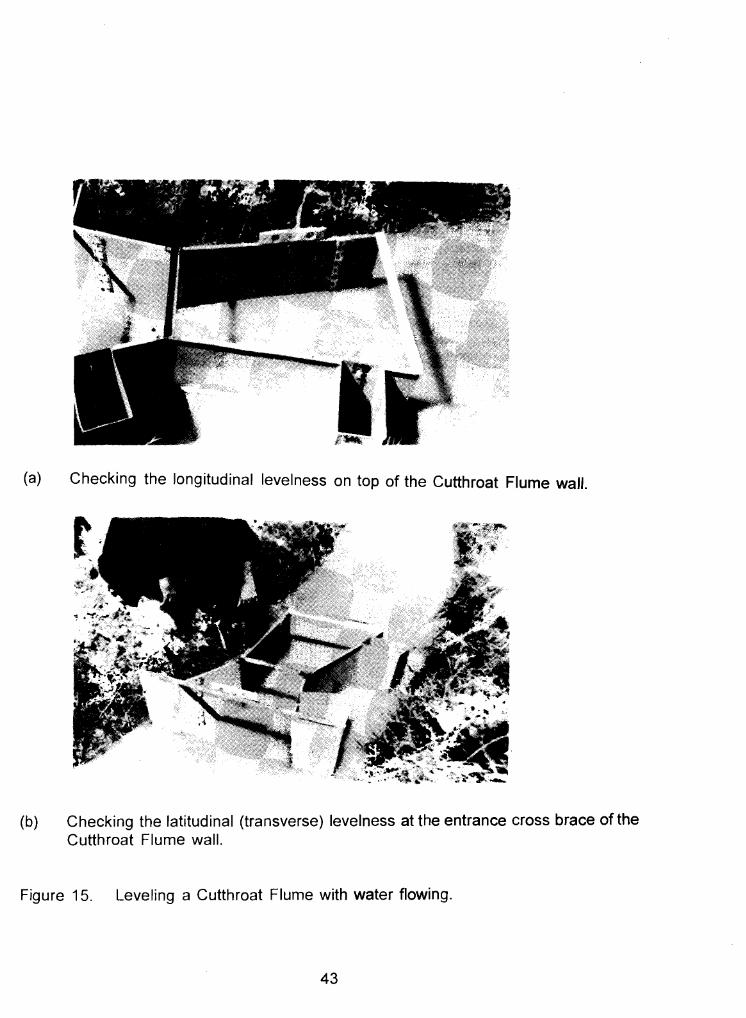
Figure 15 Leveling a Cutthroat Flume with water flowing. 43 (a) Checking the longitudinal levelness on top
of the Cutthroat Flume wall. (b) Checking the latitudinal (transverse)
levelness at the entrance cross brace of the Cutthroat Flume wall.
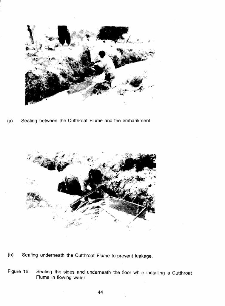
Figure 16 Sealing the sides and underneath the floor while installing a Cutthroat Flume in flowing water. 44
(a) Sealing between the Cutthroat Flume and the embankment.
(b) Sealing underneath the Cutthroat Flume to prevent leakage.
iii
List of Tables
Table 1.
Table 2.
Sizes of Cutthroat Flume commonly used in Pakistan
Free flow discharge ratings for Cutthroat Flumes having a length, L =3.0 feet
40
48
Table 3. Submerged flow multiplication factors for Cutthroat Flumes with L =3.0 feet 49
iv
CONVERTING A FABRICATED CUTTHROAT FLUME INTO A DISCHARGE MEASURING INSTRUMENT
1. GENERAL DESCRIPTION
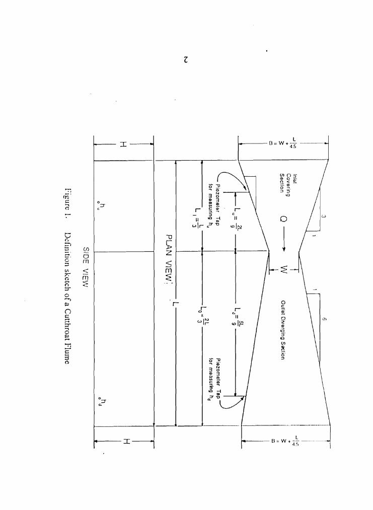
The Cutthroat Flume is a device to measure the discharge rate of flowing water
in hydraulic channels. This flume was developed during 1966-67 at the Utah water
Research Laboratory, Utah State University, Logan, Utah, U.S.A. As shown in Figure
1, the Cutthroat Flume (CTF) is simple in appearance. Since the flume has zero throat
length, this device was given the name "Cutthroat" by the developers (Skogerboe.
Hyatt,Anderson and Eggleston, 1967). but, meticulous care is needed during both
installation and the observation of upstream and downstream flow depths in order to
obtain accurate discharge measurements.
Three dimensions are required to completely specify all dimensions for a
Cutthroat Flume (CTF). The most important dimension is the throat width (W,in Figure
1). Secondly, the flume length, L, must be specified. Finally, the height of the flume
walls,H, must be listed. The information required for establishing the dimensions WkL*H
are provided in the report, "Cutthroat Flume Discharge Ratings, Size Selection ~H1d
Installation" (Skogerboe, Ren and Yang, 1993).
2. CHECKING THE FABRICATED FLUME
A newly fabricated Cutthroat Flume(CTF) should have the dimensions checked.
Unless this is done, the user will not have any idea regarding the accuracy of the
discharge measurements.
2.1 Throat Width
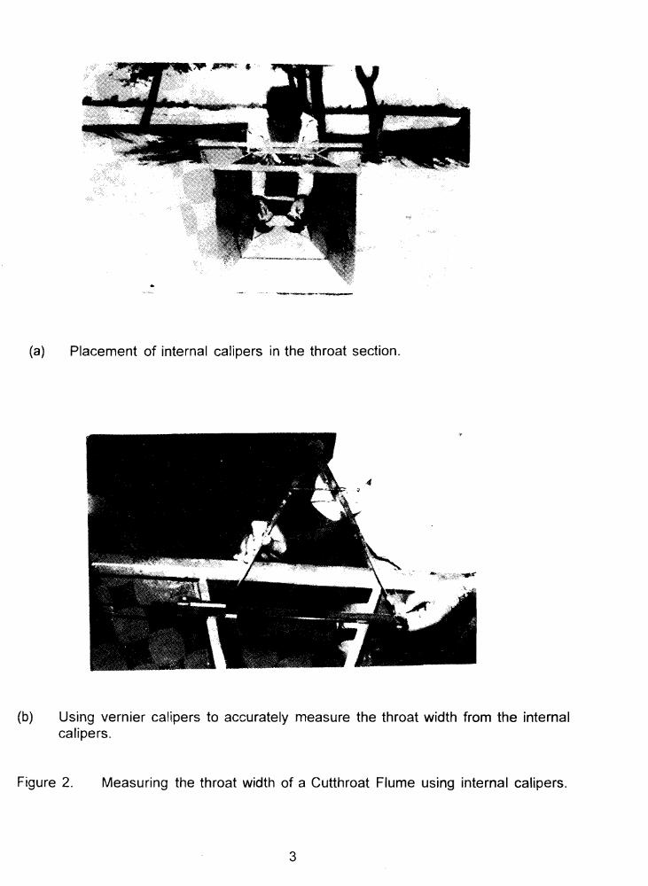
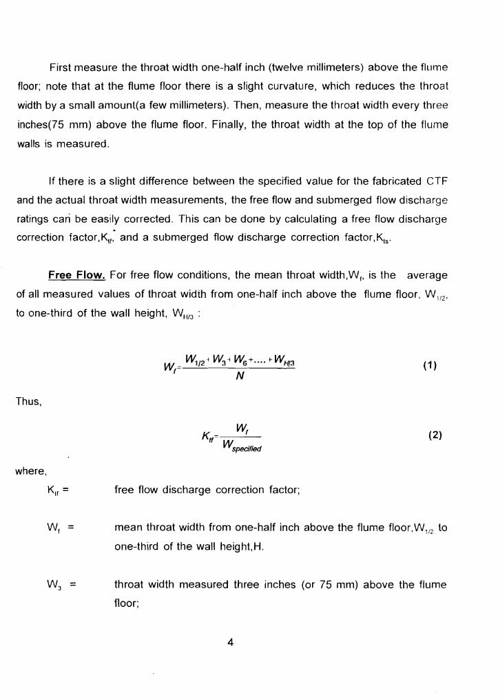
The most important dimension is the throat width,W. Steel calipers should be
used to measure the inside dimensions of the throat width as indicated in Figure 2 The
throat width, W, along the lower half of the wall height, H, is more important than the
throat width along the upper half of the wall height.
1
.,... ..;'-
f,'''~~,~
" c:J
H
-JI~ +
3:
oh~
Pie
zom
ete
r T
ap
for m
ea
surin
g
hd
6
L 1
Ou
tlet D
iverg
ing
So
clion
w~
SID
E
VIE
W
PLA
.N V
IEW
:
Definition sketch o
f a Cutthroat Flum
e
o
J
h o
u
Figure I.
Inlet C
ove
ring
S
ectio
n
c:l--L
~
.L
L~=% I
0
9 J P
inzo
rna
ter
Tap
for m
ea
surin
g
hu
_ 2L
_I
L"
La 3
L -
I1
-3
H
...)I~ +
?; II c:J
tv
.. ", .:
.. ,~
~"-"'---"~
(a) Placement of internal calipers in the throat section.
(b) Using vernier calipers to accurately measure the throat width from the internal calipers.
Figure 2. Measuring the throat width of a Cutthroat Flume using internal calipers.
3
First measure the throat width one-half inch (twelve millimeters) above the flume
floor; note that at the flume floor there is a slight curvature, which reduces the throat
width by a small amount(a few millimeters). Then, measure the throat width every three
inches(75 mm) above the flume floor. Finally, the throat width at the top of the flume
walls is measured.
If there is a slight difference between the specified value for the fabricated CTF
and the actual throat width measurements, the free flow and submerged flow discharge
ratings can be easily corrected. This can be done by calculating a free flow discharge
correction tactor.K; and a submerged flow discharge correction factor.k.;
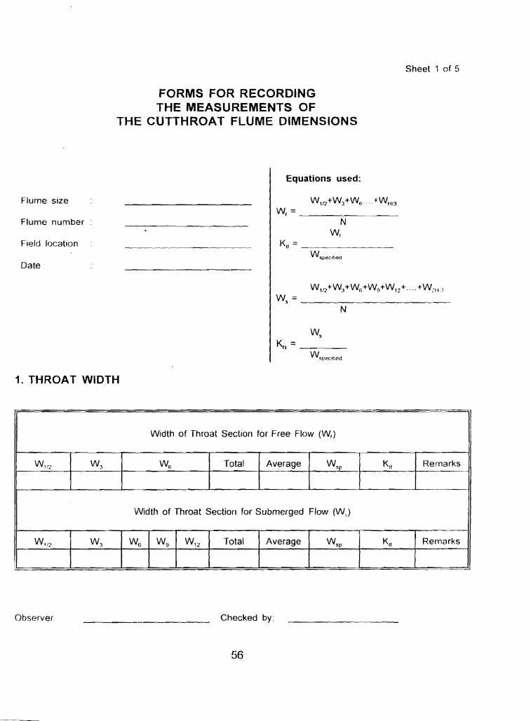
Free Flow. For free flow conditions, the mean throat width.Vv; is the average
of all measured values of throat width from one-half inch above the flume floor, W 1I2 ,
to one-third of the wall height, W~jJ3 :
~/2~ Vv'3~ ~+ .... t- WH/3W =-~------'----- (1 ) f N
Thus,
WfKtf=--- (2) WSPecified
where,
free flow discharge correction factor;
Wf = mean throat width from one-half inch above the flume floor.vv.; to
one-third of the wall height,H.
W3 = throat width measured three inches (or 75 mm) above the flume
floor:
4
= standard throat width specified to the manufacturer; and
N = number of observations.
Now, the free flow discharge rate, O, becomes:
(3)
where,
= free flow coefficient;
= free flow depth measured in the upstream stilling well; and
= free flow exponent.
5
~)
Example 1: Throat Width Correction for Free Flow conditions
Calculate the free flow discharge correction factor for a newly fabricated
Cutthroat Flume having a specified throat width of 12 inches a specified flume
length of 36 inches, and a specified wall height of '18 inches.
The following measurements are obtained by using calipers (see the
photographs in Figure 2):
= 12.047"W1I2
W3 = 12.023"
Wo = 12.017"= WH/3
Using Equation 1t
~1/2) -I-~3) + ~6) +... + ~HI3)W, _!.2::!_~_----'-"!.__~~
N
12.047 I-12.023+12.017 3
= 12.029" = Using Equation 2,
w,K" -- Wspeci'ied
K =12.029 =1.002 If 12.0
Therefore,
. n n,Q,=1.00~C/Ju
Or, O, is equal to the value of O, from Table 2 multiplied by 1.002.
6
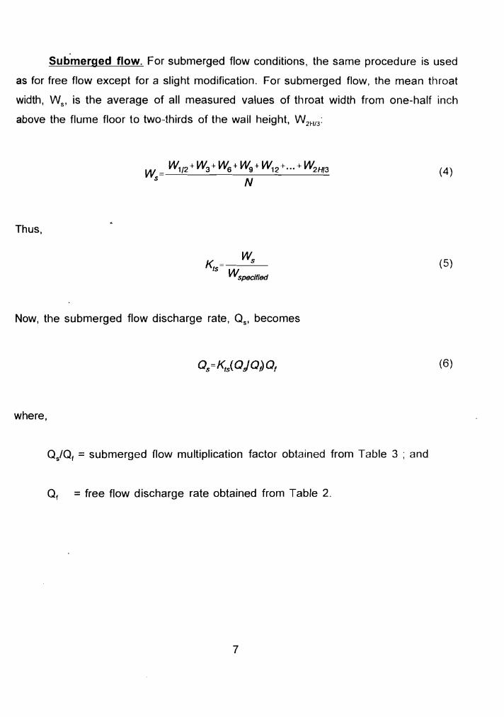
Submerged flow. For submerged flow conditions, the same procedure is used
as for free flow except for a slight modification. For submerged flow, the mean throat
width, W S 1 is the average of all measured values of throat width from one-half inch
above the flume floor to two-thirds of the wall height, W 2H13 :
W1/2 + W3 + Ws + Wg + W12 +··· + W2H/3W =---'--------------'- (4) S N
Thus,
(5)
Now, the submerged flow discharge rate, Qs' becomes
(6)
where,
Q/Qf = submerged flow multiplication factor obtained from Table 3 ; and
O, = free flow discharge rate obtained from Table 2.
7
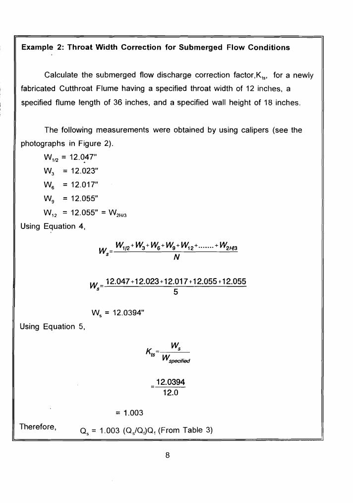
Example 2: Throat Width Correction for Submerged Flow Conditions
Calculate the submerged flow discharge correction factor.k.; for a newly
fabricated Cutthroat Flume having a specified throat width of 12 inches, a
specified flume length of 36 inches, and a specified wall height of 18 inches.
The following measurements were obtained by using calipers (see the
photographs in Figure 2).
W 1/2 = 12.0~47"
W3 = 12.023"
Ws =12.017"
Wg = 12.055"
W12 = 12.055" = W2H/3
Using Equation 4,
w =_W_1/2 +_W =--_ ---=-- W1.=.2+_"__ _= =-- _ 3 + W 6 _+_W--=-9_+_ ••••••_+_W--=2=--Hl:...:..3 S N
w = 12.047+12.023+12.017+12.055+12.055 s 5
Ws = 12.0394"
Using Equation 5,
K = Ws ts W
specified
12.0394 12.0
=1.003
Therefore,
8
2.2 Piezometer Taps
After the throat width, the second most important dimension is the length from
the throat to the upstream piezometer tap(Lu) for measuring the upstream flow
depthth.), followed by the length from the throat to the downstream piezometer tap (La)
for measuring the downstream flow depth(h d ) when submerged flow occurs in the CTF.
Upstream piezometer tap. As shown in Figure 1, the distance from the throat
to the upstream piezometer tap (L) is:
L =2L (7) u 9
Where,
L = specified length of Cutthroat Flume; and
= specified distance along the flume centerline from the throat to the
centerline of the upstream piezometer tap.
This dimension should conform with Equation 7 within an accuracy of 0.02(L/3);in other
words, the measured distance (Lu)meas should be:
(8)(Lu)meas=2l./9±O.02(l./3)
Thus, for a Cutthroat Flume having a specified length(L) of 3 feet, the measured value
of L as(Lu)meas should be within 0.02(3 feeU3) =0.02 foot of the specified value of l.,
(Equation 7).
9
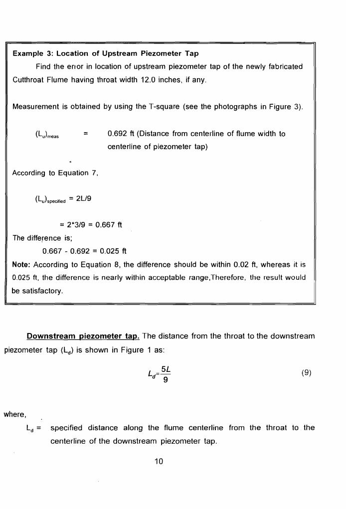
Example 3: Location of Upstream Piezometer Tap
Find the enor in location of upstream piezometer tap of the newly fabricated
Cutthroat Flume having throat width 12.0 inches, if any.
Measurement is obtained by using the T-square (see the photographs in Figure 3).
= 0.692 ft (Distance from centerline of flume width to
centerline of piezometer tap)
According to Equation 7,
=2*3/9 =0.667 ft
The difference is;
0.667 - 0.692 = 0.025 ft
Note: According to Equation 8, the difference should be within 0.02 ft, whereas it is
0.025 ft, the difference is nearly within acceptable range,Therefore, the result would
be satisfactory.
Downstream piezometer tap. The distance from the throat to the downstream
piezometer tap (Ld ) is shown in Figure 1 as:
(9)
r ,
where,
Ld = specified distance along the flume centerline from the throat to the
centerline of the downstream piezometer tap.
10
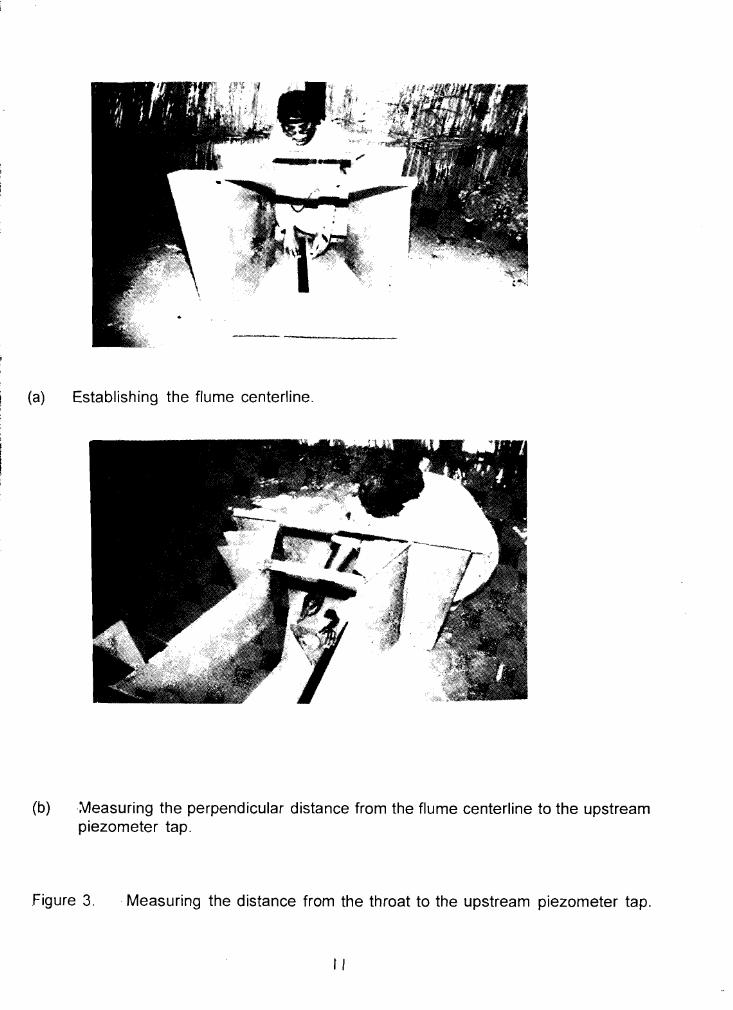
(a) Establishing the flume centerline.
(b)~easuring the perpendicular distance from the flume centerline to the upstream piezometer tap.
Figure 3. .Measuring the distance from the throat to the upstream piezometer tap.
II
Because the water surface profile in the outlet diverging section does not change so
rapidly compared with the inlet converging section, there can be more tolerance allowed
for the placement of the downstream piezometer tap (Ld).
Thus, an accuracy of 0.02(2L13) is recommended. Consequently, the measured
distance for Ld should be:
5L 2L (10)(Ld)meas=-±0.02(-)9 3
Therefore, for a Cutthroat Flume having a specified length(L) of 3 feet, the measured
value of Ld, (Ld)meas' should be within 0.02[2(3 feet)/3]= 0.04 foot of the specified value
of l., (Equation 9).
Example 4: Location of Downstream Piezometer Tap
Find the error, if any, in the location of the downstream piezometer tap of a newly fabricated Cutthroat Flume having a specified throat width of 12.0 inches, a specified length of 36 inches, and a specified wall height of 18 inches
Measurement of Ld is obtained by using the T-square (see the photographs in Figure 4)
(Ld)meas = 1.677 ft (Distance from the centerline of the flume width, perpendicular to the centerline of the piezometer tap)
Using Equation 9,
= 5L19
=5*3/9 =1.667ft
The difference is;
1.667-1.677 = 0.010 ft
Note: According to Equation (10), the difference should be within 0.04 feet. It is found that the difference is 0.01 which is excellent. In either case, the accuracy within 0.04 ft would be satisfactory.
12
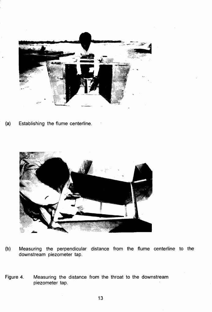
(a) Establishing the flume centerline.
(b) Measuring the perpendicular distance from the flume centerline to the downstream piezometer tap.
Figure 4. Measuring the distance from the throat to the downstream piezometer tap.
13
2.3 Entrance and Exit Widths
The next step in checking the dimensions of a fabricated Cutthroat Flume is to
measure; (1) the width at the entrance of the inlet converging section, B, and (2) the
width at the exit of the outlet diverging section, Bo. The procedure is similar to
measuring the throat width, except a scale can be used rather than calipers. The first
width measurement is made one-half inch above the floor; then, width measurement
are made 3 inches above the floor, 6 inches above the floor, etc. until the width is
measured at the top of the flume at height H above the floor. The measured values of ~
(Bj)meas and (Bo)meas are calculated from the following simple equations for a arithmetic
average:
(B)1/2 +(Bj)3 +(B)6 +•.. +(B) H (11 )(Bj) meas co N
and
(12)
where,
(B,)rneas = arithmetic average of entrance width measurements;
(Bo)meas = arithmetic average of exit width measurements;
(B,)1I2 or (BO) 1/2 = width measurement one-half inch above the flume
floor at entrance and exit, respectively;
= width measurement three inches above the flume
floor at entrance and exit. respectively;
= width measurement at top of wall at entrance and
exit, respectively; and
N = Number of Observations.
14
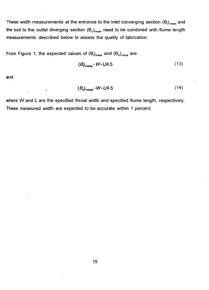
These width measurements at the entrance to the inlet converging section (Bj)meas and
the exit to the outlet diverging section (Bo)mells need to be combined with flume length
measurements described below to assess the quality of fabrication.
From Figure 1, the expected values of (BJmeas and (Bo)meas are:
(B)meas= W+Lj4.5 (13)
and
(BJmeas= W+Lj4.5 (14)
where Wand L are the specified throat width and specified flume length, respectively.
These measured width are expected to be accurate within 1 percent.
15
)
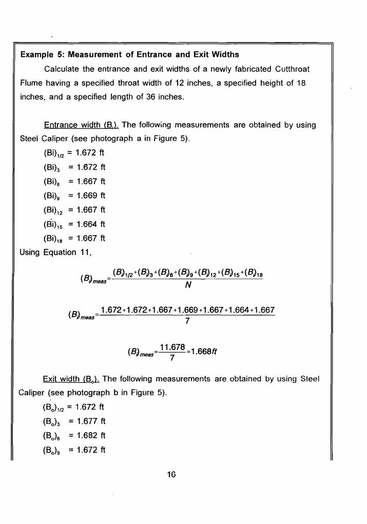
Example 5: Measurement of Entrance and Exit Widths
Calculate the entrance and exit widths of a newly fabricated Cutthroat
Flume having a specified throat width of 12 inches, a specified height of 18
inches, and a specified length of 36 inches.
Entrance width (BjL. The following measurements are obtained by using
Steel Caliper (see photograph a in Figure 5).
(8i)1/2 =1.672 ft
(Bi)3 = 1.672 ft
(Bi)6 =1.667 ft
(Bi)9 = 1.669 ft
(Bi)12 = 1.667 ft
(Bi)15 = 1.664 ft
(Bi)18 = 1.667 ft
Using Equation 11,
8 ) = 1.672+1.672+1.667+1.669+1.667+1.664+1.667( iJmeas 7
(8 \ 11.678 - 1 668ft Pmeas 7 .
Exit width {BoL The following measurements are obtained by using Steel
Caliper (see photograph b in Figure 5).
(BO)1/2 = 1.672 ft
(BO)3 = 1.677 ft
(80 )6 = 1.682 ft
(80 )9 =1.672 ft
16
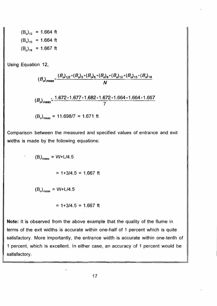
(BO)12 = 1.664 ft
(BO)15 =1.664 ft
(~0)18 = 1.667 ft
Using Equation 12,
(BcJ 1/2+(BcJ3 +(BcJa +(BcJ9 +(BcJ12 +(BcJ15 +(BcJ 18 (BcJmS8S N
(B \ ;, 1.672+1.677+1.682+1.672+1.664+1.664+1.667 oImS8S 7
(Bo)meas = 11.698/7 = 1.671 ft
Comparison between the measured and specified values of entrance and exit
widths is made by the following equations:
(B)meas = W+U4.5
= 1+3/4.5 = 1.667 ft
= 1+3/4.5 = 1.667 ft
Note: It is observed from the above example that the quality of the flume in
terms of the exit widths is accurate within one-half of 1 percent which is quite
satisfactory. More importantly, the entrance width is accurate within one-tenth of
1 percent, which is excellent. In either case, an accuracy of 1 percent would be
satisfactory.
17
, I
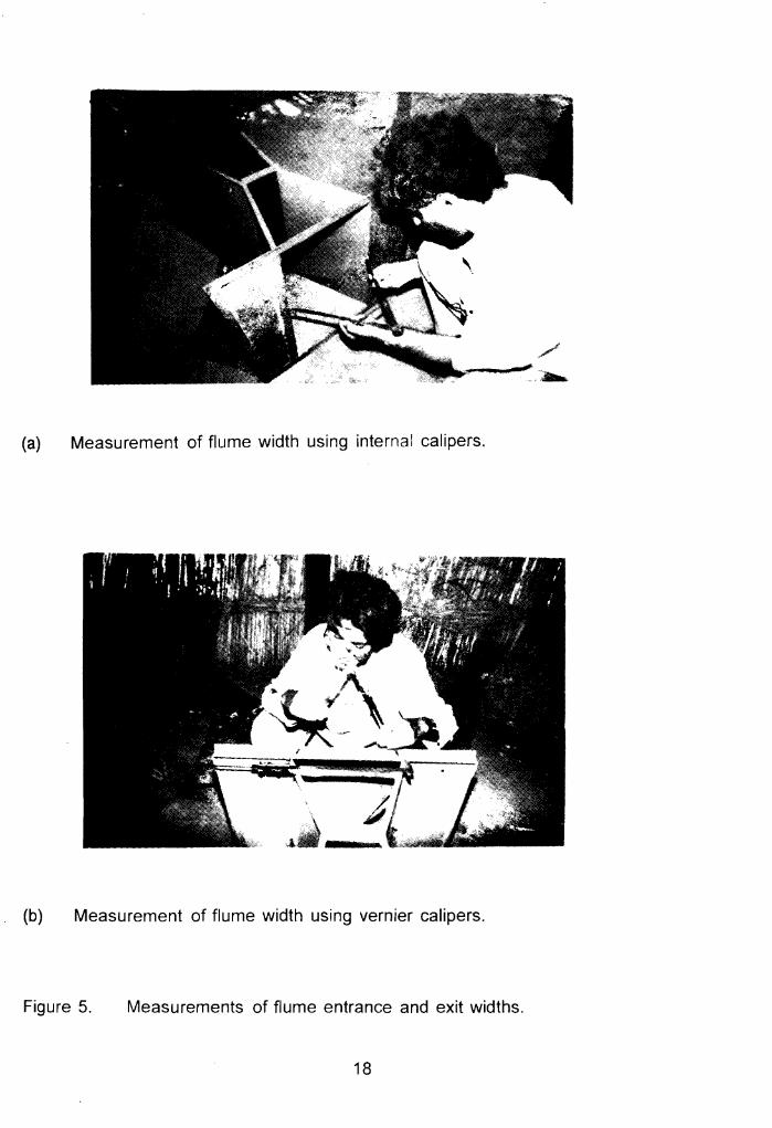
(a) Measurement of flume width using internal calipers.
(b) Measurement of flume width using vernier calipers.
Figure 5. Measurements of flume entrance and exit widths.
18
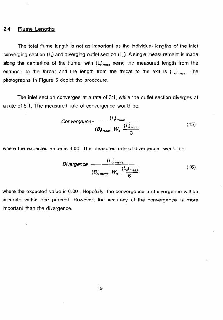
2.4 Flume Lengths
The total flume length is not as important as the individual lengths of the inlet
converging section (Lj) and diverging outlet section (L ) . A single measurement is made o
along the centerline of the flume, with (L;)meas being the measured length from the
entrance to the throat and the length from the throat to the exit is (Lo}rneas. The
photographs in Figure 6 depict the procedure.
The inlet section converges at a rate of 3:1, while the outlet section diverges at
a rate of 6:1. The measured rate of convergence would be;
Convergence= (LJmeas
(B) - W _ (LJmeas (15)
ilmeas 5 3
where the expected value is 3.00. The measured rate of divergence would be:
(LdmeasDivergence ------=----=-~--
(B \ - W (Ldmeas (16)
oJmess 5 6
where the expected value is 6.00 . Hopefully, the convergence and divergence will be
accurate within one percent. However, the accuracy of the convergence is more
important than the divergence.
19
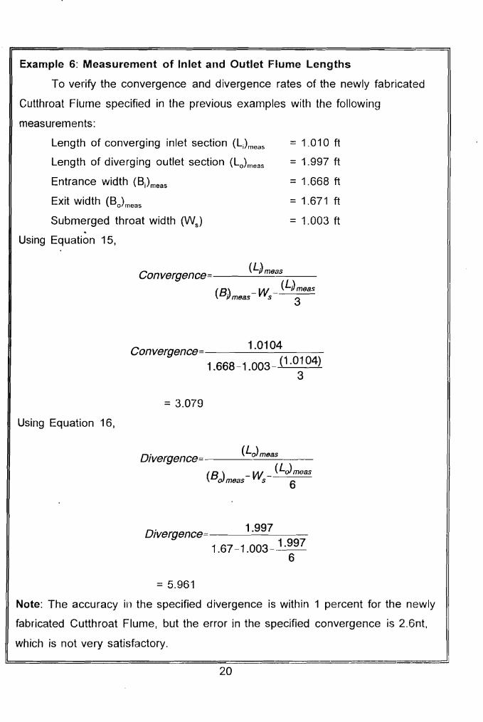
Example 6: Measurement of Inlet and Outlet Flume Lengths
To verify the convergence and divergence rates of the newly fabricated
Cutthroat Flume specified in the previous examples with the following
measurements:
Length of converging inlet section (LJmeas =1.010ft
Length of diverging outlet section (Lo)meas =1.997ft
Entrance width (B)meas =1.668ft
Exit width (Bo)meas =1.671ft
Submerged throat width (Ws) =1.003ft
Using Equation 15,
(LJmeasConvergence -------
(8 ) - W (LJmeBs u mess s 3
1.0104Convergence 1.668-1.003 _ (1.0104)
3
= 3.079
Using Equation 16,
Divergence= (Lo)meas
(B \ - W _ (LjmeasoJmeas s 6
1.997Divergence 1.67-1.003- 1.997
6
= 5.961
Note: The accuracy in the specified divergence is within 1 percent for the newly
fabricated Cutthroat Flume, but the error in the specified convergence is 2.6nt,
which is not very satisfactory.
20
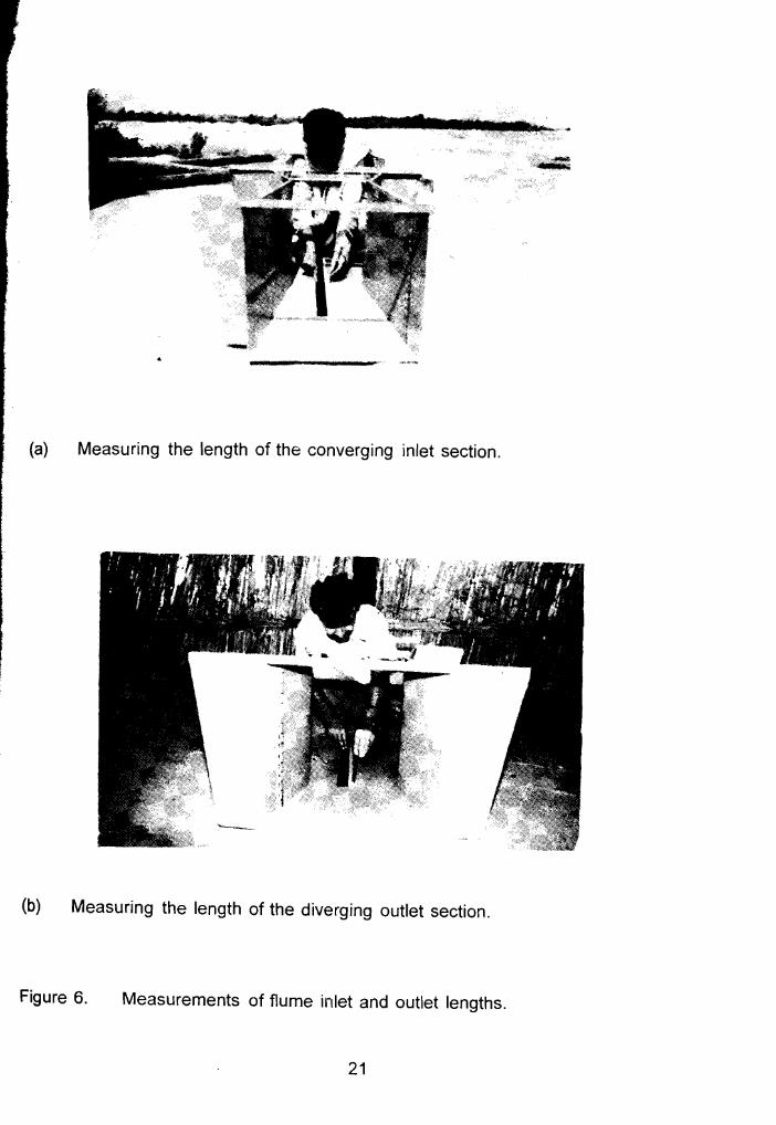
I,
(a) Measuring the length of the converging inlet section.
(b) Measuring the length of the diverging outlet section.
Figure 6. Measurements of flume inlet and outlet lengths.
21
~)
2.5 Summary
The most critical dimension for a Cutthroat Flume is the throat width, W. The
accuracy is measured by W f (Equation 1) and Ws (Equation 4). Fortunately, if the
measured values of Wf and W differ from the specified throat width, W, then correction s
coefficients can be calculated (Equations 2 and 5), so that if free flow occurs.O, can be
calculated from Equation 3; likewise, if subrnerqed flow occurs, 011 can be computed
from Equation 6.
The second most important dimension is the length along the flume centerline
from the throat to the piezometer tap in the inlet converging section, with the accuracy
criterion specified in Equation 8. The next most important dimension is the length along
the flume centerline from the throat to the piezometer tap in the outlet diverging section,
with the required accuracy specified by Equation 10. If the required accuracy is not met,
then the piezometer taps should be sealed and new piezometer taps placed at the
proper location(s).
Finally, the rate of convergence (Equation 15) for the inlet section is quite
important, while the rate of divergence (Equation 16) is less important. However, the
convergence and divergence are good indicators regarding the quality of the fabricated
Cutthroat Flume.
In order to facilitate this procedure, appropriate forms have been prepared, which
have been placed in the annex. These forms can be photo copied for field use, or they
can be placed on a computer. A complete set of the forms are required for each
fabricated flume.
3. CREATING AN INSTRUMENT
Often, a considerable amount of the accuracy in a Cutthroat Flume is lost due
to a variety of reasons, but the two most important reasons are:(1) the zero reading on
the staff gage in either stilling well (for measuring the upstream flow depth, h,
22
or the downstream flow depth, hd) is assumed to correspond with the invert floor of the
flume ; and (2) when installing a flume, the top of the walls, along with the braces
between t~e walls, are assumed to be perfectly parallel with the flume floor. In order
to convert the Cutthroat Flume into an instrument, these assumptions must be
overcome by: (1) determining the correction to each stilling well gauge (h; and hd ) so
that the gauge readings can be converted to true values of h; and hd ; and (2)
identifying locations for placing a spirit level on the top of the wall for longitudinal
levelness and on the cross braces for latitudinal (, transverse) levelness that can be
used when installing a portable Cutthroat Flume in a channel with flowing water. The
procedures that follow will accomplish these tasks in inverse order for a portable flume.
For a permanent installation, the same procedures would apply, except that finding
locations on top of the flume that are parallel to the flume floor would not be necessary,
but still considerable effort would go into assuring that the flume floor is level. There are
forms in the annex that can be used to record the data while doing the following
procedures.
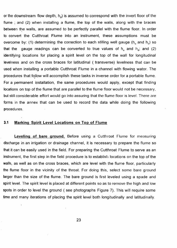
3.1 Marking Spirit Level Locations on Top of Flume
Leveling of bare ground. Before using a Cutthroat Flume for measuring
discharge in an irrigation or drainage channel, it is necessary to prepare the flume so
that it can be easily used in the field. For preparing the Cutthroat Flume to serve as an
instrument, the first step in the field procedure is to establish locations on the top of the
walls, as well as on the cross braces, which are level with the flume floor, particularly
the flume floor in the vicinity of the throat. For doing this, select some bare ground
larger than the size of the flume. The bare ground is first leveled using a spade and
spirit level. The spirit level is placed at different points so as to remove the high and low
spots in order to level the ground ( see photographs Figure 7). This will require some
time and many iterations of placing the spirit level both longitudinally and latitudinally.
23
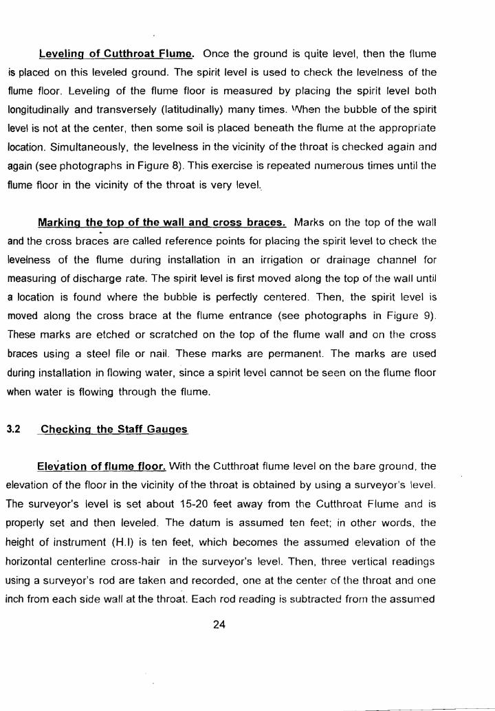
Leveling of Cutthroat Flume. Once the ground is quite level, then the flume
is placed on this leveled ground. The spirit level is used to check the levelness of the
flume floor. Leveling of the flume floor is measured by placing the spirit level both
longitudinally and transversely (latitudinally) many times. \Nhen the bubble of the spirit
level is not at the center, then some soil is placed beneath the flume at the appropriate
location. Simultaneously, the levelness in the vicinity of the throat is checked again and
again (see photographs in Figure 8). This exercise is repeated numerous times until the
flume floor in the vicinity of the throat is very level.,
Marking the top of the wall and cross braces. Marks on the top of the wall
and the cross braces are called reference points for placing the spirit level to check tile
levelness of the flume during installation in an irrigation or drainage channel for
measuring of discharge rate. The spirit level is first moved along the top of the wall until
a location is found where the bubble is perfectly centered. Then, the spirit level is
moved along the cross brace at the flume entrance (see photographs in Figure 9).
These marks are etched or scratched on the top of the flume wall and on the cross
braces using a steel file or nail. These marks are permanent. The marks are used
during installation in flowing water, since a spirit level cannot be seen on the flume floor
when water is flowing through the flume.
3.2 Checking the Staff Gauges
Elevation of flume floor. With the Cutthroat flume level on the bare ground, the
elevation of the floor in the vicinity of the throat is obtained by using a surveyor's level.
The surveyor's level is set about 15-20 feet away from the Cutthroat Flume and is
properly set and then leveled. The datum is assumed ten feet; in other words, the
height of instrument (H.I) is ten feet, which becomes the assumed elevation of the
horizontal centerline cross-hair in the surveyor's level. Then, three vertical readings
using a surveyor's rod are taken and recorded, one at the center of the throat and one
inch from each side wall at the throat. Each rod reading is subtracted from the assumed
24
.
Checking the levelness of the bare ground.
(b) Checking the transverse levelness of the ground.
Figure 7. Leveling of bare ground.
25
(a) Checking the level of the flume floor in the longitudinal direction.
'W'.
Leveling the Cutthroat Flume on bare ground.
(b) Checking the level of the flume floor in the latitudinal (transverse) direction.
Figure 8.
26
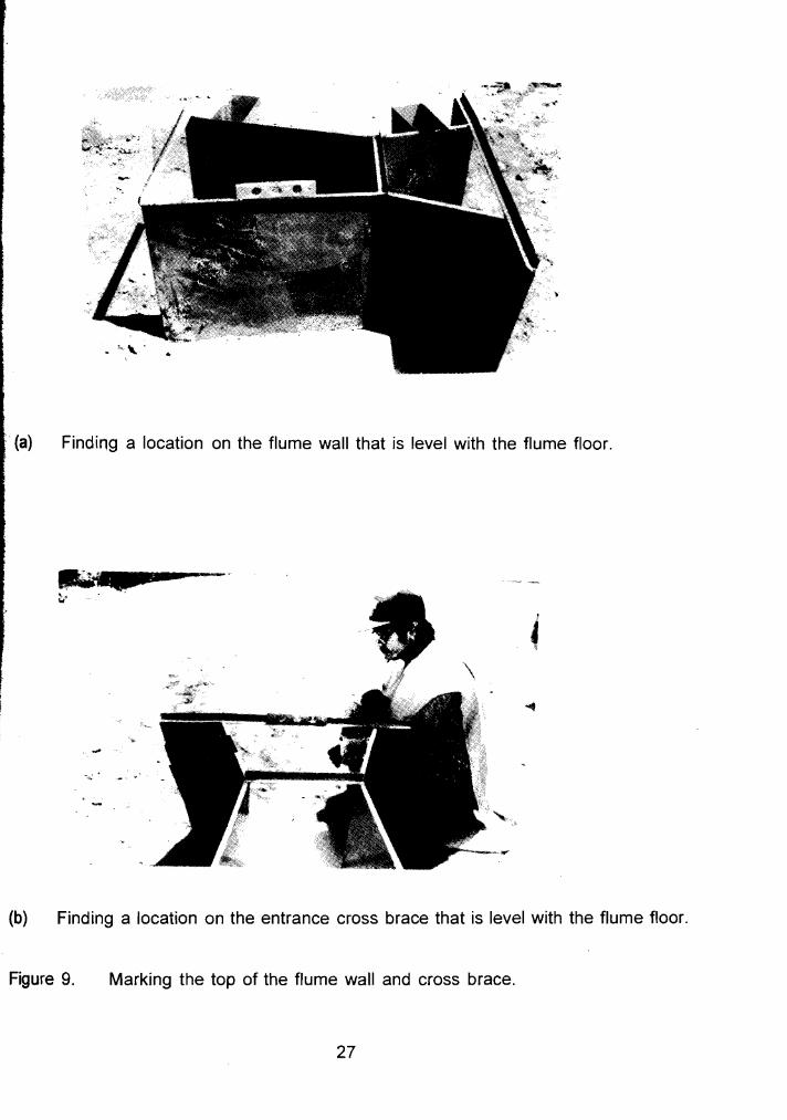
Finding a location on the flume wall that is level with the flume floor .
......(w"
-2---
(b) Finding a location on the entrance cross brace that is level with the flume floor.
Figure 9. Marking the top of the flume wall and cross brace.
27
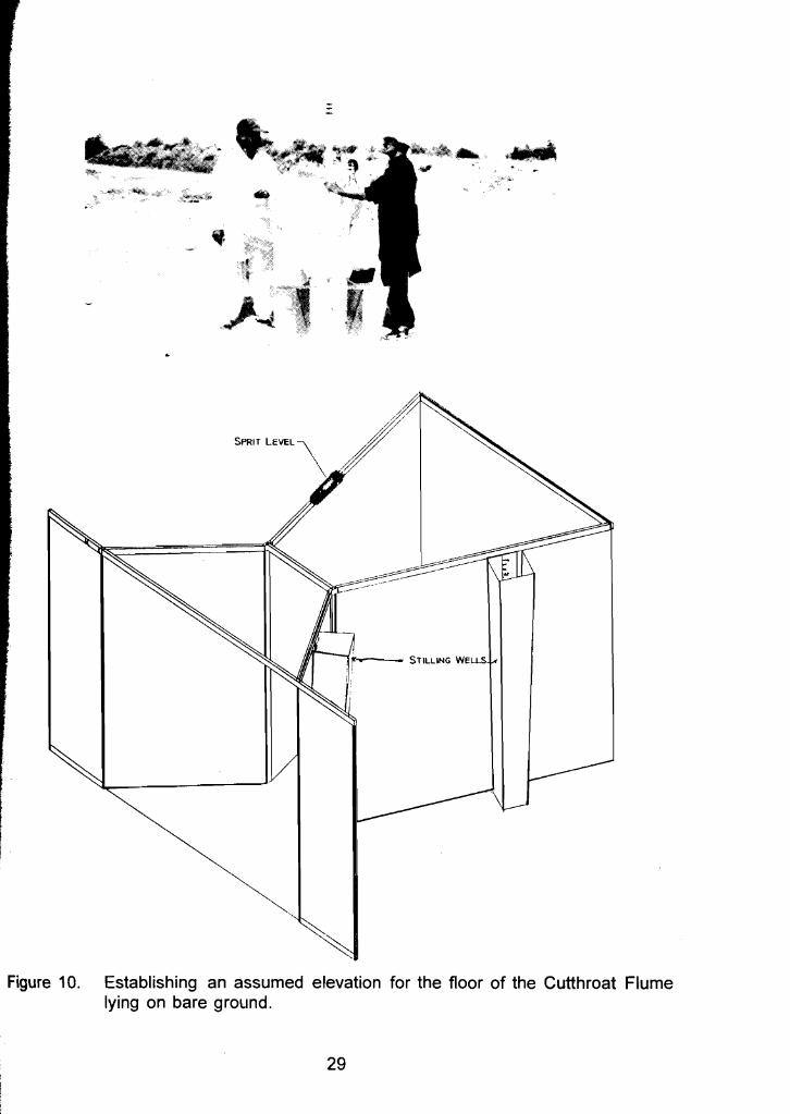
29
'Ir---rrir----- STILLING WEUS
Establishing an assumed elevation for the floor of the Cutthroat Flume lying on bare ground.
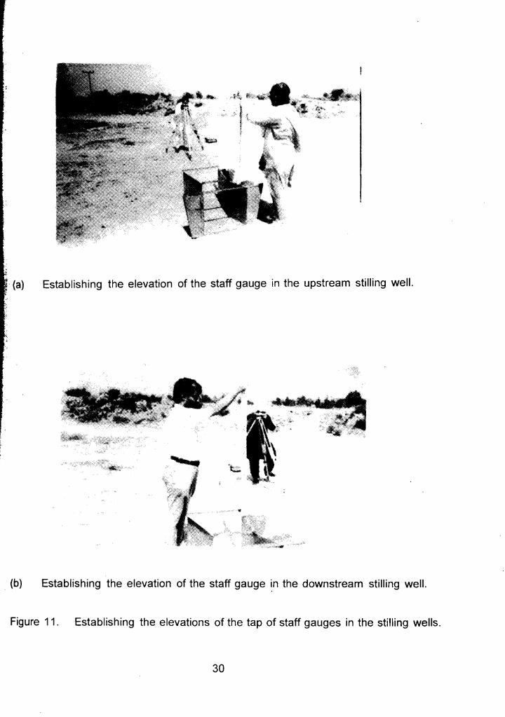
Establishing the elevation of the staff gauge in the upstream stilling well.
(b) Establishing the elevation of the staff gauge in the downstream stilling well.
Figure 11. Establishing the elevations of the tap of staff gauges in the stilling wells.
30
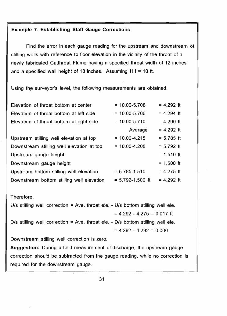
Example 7: Establishing Staff Gauge Corrections
Find the error in each gauge reading for the upstream and downstream of
stilling wells with reference to floor elevation in the vicinity of the throat of a
newly fabricated Cutthroat Flume having a specified throat width of 12 inches
and a specified wall height of 18 inches. Assuming H.I =10ft.
Using the surveyor's level, the following measurements are obtained:
Elevation of throat bottom at center = 10.00-5.708 =4.292 ft
Elevation of throat bottom at left side = 10.00-5.706 =4.294 ft
Elevation of throat bottom at right side = 10.00-5.710 = 4.290 ft
Average = 4.292 ft
Upstream stilling well elevation at top = 10.00-4.215 = 5.785 ft
Downstream stilling well elevation at top = 10.00-4.208 = 5.792 ft
Upstream gauge height =1.510ft
Downstream gauge height = 1.500 ft
Upstream bottom stilling well elevation = 5.785-1.510 = 4.275 ft
Downstream bottom stilling well elevation = 5.792-1.500 ft = 4.292 ft
Therefore,
Uls stilling well correction =Ave. throat ele. - Uls bottom stilling well ele.
= 4.292 - 4.275 = 0.017 ft
DIs stilling well correction = Ave. throat ele. - DIs bottom stilling well ele.
= 4.292 - 4.292 = 0.000
Downstream stilling well correction is zero.
Suggestion: During a field measurement of discharge, the upstream gauge
correction should be subtracted from the gauge reading, while no correction is
required for the downstream gauge.
31
4. INSTALLATION OF CUTTHROAT FLUME
4.1 Site Selection
Any flow measuring device must be properly installed to yield adequate results.
The first consideration prior to installing a Cutthroat Flume is the location or site of the
structure. The flume should be placed in a straight section of channel. If operating
conditions require frequent changing of the discharge, the flume may be conveniently
located near a 'Point of diversion or regulating gate. However, care should be taken to
see that the flume is not located too near a gate or control structure (e.g. outlet)
because of unstable or surging effects which might result downstream from the
constriction.
After the site has been selected, it is necessary to determine certain design
criteria. The maximum quantity of water to be measured, the depth of flow in the
channel corresponding to this discharge, and the allowable head loss through the flume
must be determined. The head loss may be taken as the difference in water surface
elevation between the flume entrance and exit, which is approximately equal to hlJ-hd .
The downstream depth of flow will remain essentially the same after installation of the
flume as it was prior to installation, but the upstream depth will increase by the head
loss. The allowable increase in upstream depth may be limited by the height of the
canal banks upstream from the flume. Such a limiting condition dictates the minimum
flume size, and may require operation as a submerged flow structure.
A properly installed Cutthroat Flume is aligned straight with the channel and
should be level longitudinally and laterally. Flumes tend to settle in time, with the exit
usually becoming lower than the entrance.
32
C.',._ rj
Experience both in the laboratory and the field indicates that a transition structure
between the open channel and Cutthroat Flume is not necessary. However, the ratio
of upstream flow depth to flume length (hJL) should be 0.33, or less, for free flow
conditions. For most installations in flat gradient channels, this will insure that approach
conditions will satisfy the laboratory conditions under which the ratings were developed.
Measurements should be made in the Cutthroat Flume by the lise of piezometers
connected to stilling wells. The staff gauges must be carefully referenced to the
elevation of the flume floor. Stilling wells have the advantage of providing a calm water
surface compared with the fluctuation or " bounce" of the water surface that usually
exists within the Cutthroat Flume.
4.2 Installation to Ensure Free Flow
If circumstances allow, it is preferable to have a flow measuring device operate
under free flow conditions. The obvious advantage is that only the upstream flow depth
need be measured to determine the discharge. Also, the accuracy in determining the
discharge rate is better for free flow as compared with submerged flow. The procedure
to follow for installing a Cutthroat Flume to operate under free flow conditions is listed
below:
1. Determine the maximum flow rate to be measured.
2. At the site selected for installing the flume, locate the high water line on the
canal bank and determine the maximum depth of flow.
3. For -a selected flume size, use the free flow discharge rating. Calculate the
depth of water that corresponds to the maximum discharge capacity of the canal.
33
4. Place the floor of the flume at an elevation which does not exceed humultiplied
by the transition submergence (Sthu) below the high water line. Generally, the
flume bottom should be placed as high as grade and other conditions permit
to insure free flow.
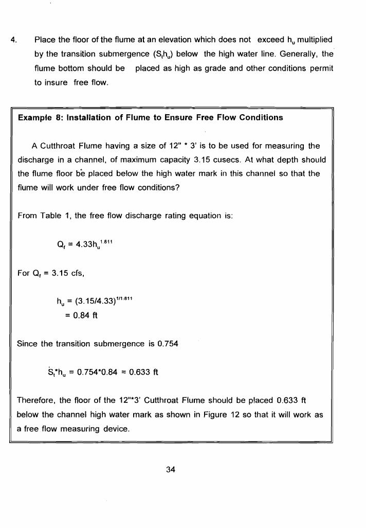
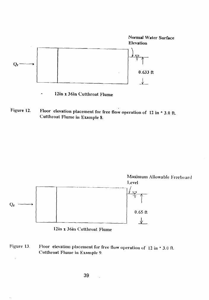
Example 8: Installation of Flume to Ensure Free Flow Conditions
A Cutthroat Flume having a size of 12" * 3' is to be used for measuring the
discharge in a channel, of maximum capacity 3.15 cusecs. At what depth should
the flume floor be placed below the high water mark in this channel so that the
flume will work under free flow conditions?
From Table 1, the free flow discharge rating equation is:
For O, = 3.15 cfs,
h = (3.15/4.33)1/1,811u
= 0.84 ft
Since the transition submergence is 0.754
Sthu =0.754*0.84 =0.633 ft
Therefore, the floor of the 12"*3' Cutthroat Flume should be placed 0.633 ft
below the channel high water mark as shown in Figure 12 so that it will work as
a free flow measuring device.
34
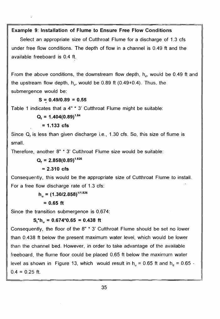
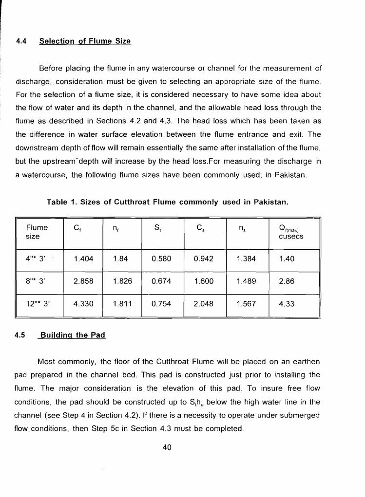
Example 9: Installation of Flume to Ensure Free Flow Conditions
Select an appropriate size of Cutthroat Flume for a discharge of 1.3 cfs
under free flow conditions. The depth of flow in a channel is 0.49 ft and the
available freeboard is 0.4 ft.
From the above conditions, the downstream flow depth, hd , would be 0.49 ft and
the upstream flow depth, hu ' would be 0.89 ft (0..49+0.4). Thus, the
submergence would be:
5 = 0.49/0.89 = 0.55 ~
Table 1 indicates that a 4" * 3' Cutthroat Flume might be suitable:
Of = 1.404(0.89)1.84
= 1.133 cfs
Since O, is less than given discharge Le., 1.30 cfs. So, this size of flume is
small.
Therefore, another 8" * 3' Cutthroat Flume size would be suitable:
Of =2.858(0.89)1.826
= 2.310 cfs
Consequently, this would be the appropriate size of Cutthroat Flume to install.
For a free flow discharge rate of 1.3 cfs:
h = (1.30/2.858)111.826u
= 0.65 ft
Since the transition submergence is 0.674:
Sthu =0.674*0.65 =0.438 ft
Consequently, the floor of the 8" * 3' Cutthroat Flume should be set no lower
than 0.438 ft below the present maximum water level, which would be lower
than the channel bed. However, in order to take advantage of the available
freeboard, the flume floor could be placed 0.65 ft below the maximum water
level as shown in Figure 13, which would result in hu =0.65 ft and hd =0.65
0.4 =0.25 ft.
35
4.3 Installation under Submerged Flow Conditions
The existence of certain conditions, such as insufficient grade or the growth of
moss and vegetation, sometimes makes it impossible or impractical to install a flume
to operate under free flow condition. Where such situations exist, a flume may be set
in the channel to operate under submerged flow conditions. The principal advantage
of submerged flow operation is the smaller head loss which occurs in the flume as
compared with free flow. This reduction in head loss may mean that the channel banks
upstream from the flume do not have to be raised to enable the same maximum flow
capacity in the channel that existed prior to the installation of the flume. When a flat
bottomed Cutthroat Flume is installed to operate under submerged flow conditions. the
flume floor may be placed at the canal bottom. This placement will allow quicker
drainage of the canal section upstream from the flume, particularly for flow rates which
are less than the maximum discharge. The following procedure should be used in
placing a Cutthroat Flume to operate under submerged flow conditions.
1. Determine the maximum flow rate,Qs' to be measured.
2. On the channel bank, where the flume is to be installed, locate the high water
line to determine the maximum flow depth.
3. Giving consideration to the amount of free-board in the channel at maximum
discharge and maximum flow depth,determine how much higher the water
surface can be raised in the channel upstream from the flume location.
4. With the floor of the flume being placed at essentially the same elevation as the
bottom of the channel, the maximum depth of flow (Step 2) becomes hd , and the
additional amount that the water surface in the canal can be raised (Step 3),
becomes hu-hd . Using this information, the submergence, hd/hu can be
computed.
36
5. Select an appropriate size of Cutthroat Flume by trial-and- error. Knowing Qs' S
and hu is important in guiding the procedure.
a. First, the submerged flow rating tables would be consulted. The submerged
flow multiplication factor, Q/Qf, could be read for each flume size for the known
value of submergence, S. Actually, by already knowing (or having an estimate
of) O, will indicate to some extent the range of flume sizes that might be
appropriate.
b. ~
Then, the estimated or known value of O, can be divided by the submerged flow
multiplication factor, Q/Qf, for each flume size to arrive at a required value of the
free flow discharge rate.O,
c. Now, the known maximum value of the upstream flow depth.h , can be used
in the free flow discharge rating tables for each flume size being investigated
in order to determine whether the value of O, in the rating table equals or
exceeds the required value of O, calculated in Step 5b.
d. Based on the results from Step 5c, the most appropriate size
can be selected.
of Cutthroat Flume
37
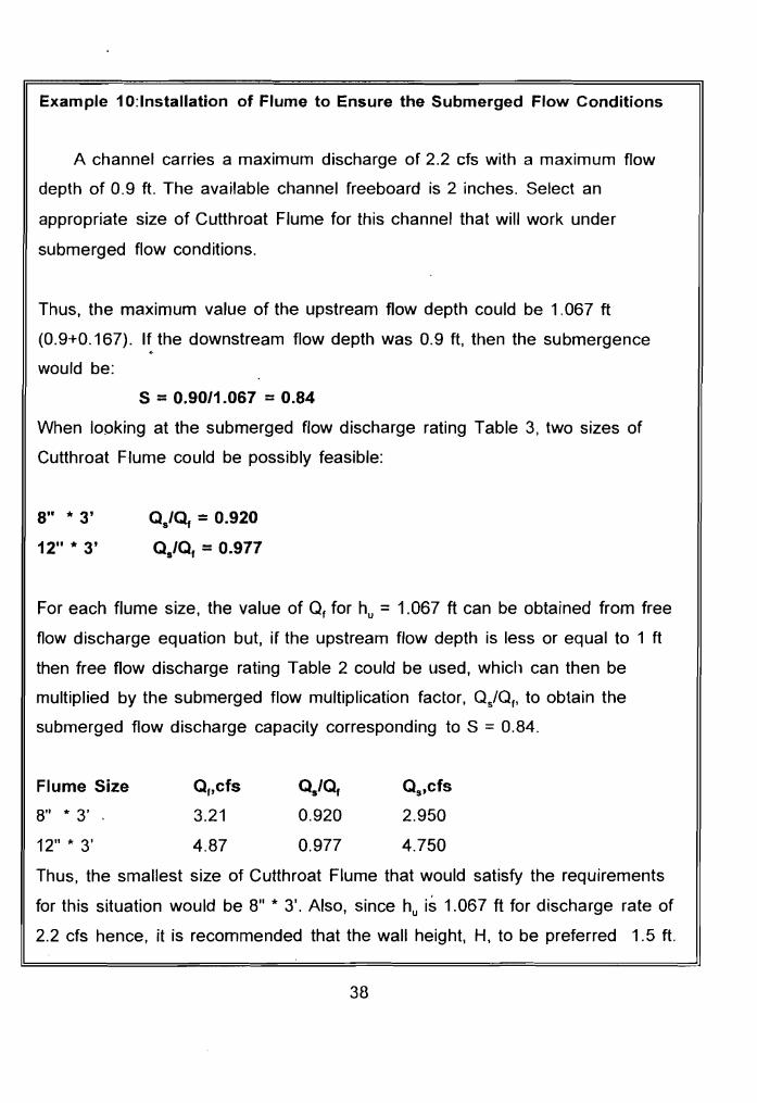
Example 10:lnstallation of Flume to Ensure the Submerged Flow Conditions
A channel carries a maximum discharge of 2.2 cfs with a maximum flow
depth of 0.9 ft. The available channel freeboard is 2 inches. Select an
appropriate size of Cutthroat Flume for this channel that will work under
submerged flow conditions.
Thus, the maximum value of the upstream flow depth could be 1.067 ft
(0.9+0.167). If the downstream flow depth was 0.9 ft, then the submergence ~
would be:
S =0.90/1.067 =0.84
When looking at the submerged flow discharge rating Table 3, two sizes of
Cutthroat Flume could be possibly feasible:
8" * 3' Qs/eJ. = 0.920
12" * 3' Qs/Q, = 0.977
For each flume size, the value of Q, for hu =1.067 ft can be obtained from free
flow discharge equation but, if the upstream flow depth is less or equal to 1 ft
then free flow discharge rating Table 2 could be used, which can then be
multiplied by the submerged flow multiplication factor, Q/Q" to obtain the
submerged flow discharge capacity corresponding to S =0.84.
Flume Size Q"cfs Qs/Q, Qs,cfs
8" * 3' . 3.21 0.920 2.950
12" * 3' 4.87 0.977 4.750
Thus, the smallest size of Cutthroat Flume that would satisfy the requirements
for this situation would be 8" * 3'. Also, since hu is 1.067 ft for discharge rate of
2.2 cfs hence, it is recommended that the wall height, H, to be preferred 1.5 ft.
38
Qf---'
Normal Water Surface Elevation
T i 0.633 n
12in x 361n Cutthroat Flume
Figure 12. Floor elevation placement for free now operation of 12 In .. 3.0 It,
Cutthroat Flume ill Example 8.
Maximum Allowable Freeboard Level
0.65 II
12in x 36in Cutthroat Flume
Figure 13. Floor elevation placement for free now operation or 12 in • 3.0 11. Cutthroat Flume in Example 9.
39
4.4 Selection of Flume Size
Before placing the flume in any watercourse or channel for the measurement of
discharge,. consideration must be given to selecting an appropriate size of the flume.
For the selection of a flume size, it is considered necessary to have some idea about
the flow of water and its depth in the channel, and the allowable head loss through the
flume as described in Sections 4.2 and 4.3. The head loss which has been taken as
the difference in water surface elevation between the flume entrance and exit. The
downstream depth offlow will remain essentially the same after installation of the flume,
but the upstreamdepth will increase by the head loss.For measuring the discharge in
a watercourse, the following flume sizes have been commonly used; in Pakistan.
Table 1. Sizes of Cutthroat Flume commonly used in Pakistan.
Flume size
C, n, St Cs ns Q'(max) cusecs
4"* 3' 1.404 1.84 0.580 0.942 1.384 1.40
8"* 3' 2.858 1.826 0.674 1.600 1.489 2.86
12"* 3' 4.330 1.811 0.754 2.048 1.567 4.33
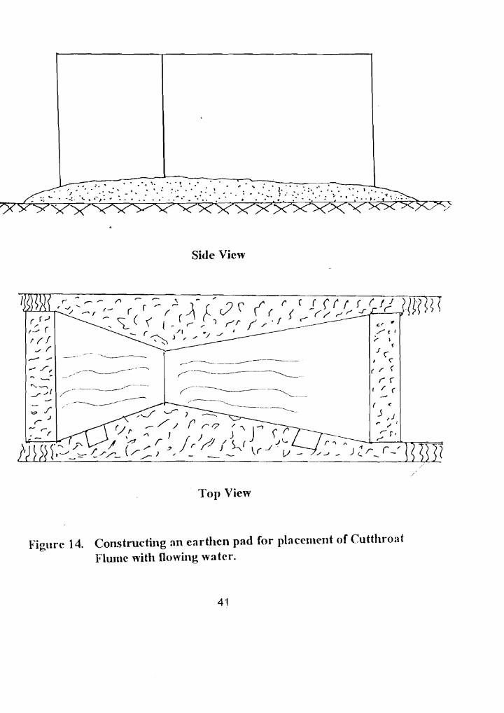
4.5 Building the Pad
Most commonly, the floor of the Cutthroat Flume will be placed on an earthen
pad prepared in the channel bed. This pad is constructed just prior to installing the
flume. The major consideration is the elevation of this pad. To insure free flow
conditions, the pad should be constructed up to Slhu below the high water line in the
channel (see Step 4 in Section 4.2). If there is a necessity to operate under submerged
flow conditions, then Step 5c in Section 4.3 must be completed.
40
".. " .. eo. ... ~ ...... .. •
: .....
Side View
( t :» .: r 1('/.."r
,,------------------- -
-~----~-_._-- ----...,.
( <:
J ,J ~ " I
r- r. r '\ " _.&o--'-r_--,-~~~
/J _ ) Zr:_ r -'
,/
Top View
Figure 14. Constructing an earthen pad for placement of Cutthroat Flume with flowing watcr.
Before beginning the construction of the pad, the top elevation of the pad should
be marked using a stick pounded into the channel bed with the top of the stick being
the pad elevation, or a pile of rocks placed on the channel bed, or a pile of bricks.
Then, soil can be used to build the pad. Sad (soil with plant material) is useful because
it is not so easily eroded. The size of the pad needs to be slightly larger than the area
of the flume floor.
4.6 Leveling the Installed Flume
Once the pad, has been constructed, the Cutthroat Flume is placed on the pad.
A spirit level is first placed on the flume wall at a location previously marked (Section
3.1) as being parallel with the flume floor. After leveling the flume longitudinally, the
spirit level is placed at the marked place on a cross bar so that the flume can be
leveled transversely.
4.7 Sealing the Sides and Underneath the Flume
Once the Cutthroat Flume has been leveled on the pad, the sides of the flume
are sealed with hard soil containing grass, because soil without grass could not
withstand the flowing water. The sides and underneath the flume are carefully sealed
so that very little leakage could occur when observing the flow rate.
Once most of the flow is passing through the flume,the longitudinal and latitudinal
levelness of the flume should again be checked using the spirit level. Then, more soil
should be placed along the sides of the flume. Again, the levelness should be checked.
This procedure should be repeated a number of times until the sides are sealed. Then,
more soil should be placed underneath the flume entrance to be sure that there is no
leakage beneath the flume.
42
(a) Checking the longitudinal levelness on top of the Cutthroat Flume wall.
(b) Checking the latitudinal (transverse) levelness at the entrance cross brace of the Cutthroat Flume wall.
Figure 15. Leveling a Cutthroat Flume with water flowing.
43
(a) Sealing between the Cutthroat Flume and the embankment.
(b) Sealing underneath the Cutthroat Flume to prevent leakage.
Figure 16. Sealing the sides and underneath the floor while installing a Cutthroat Flume in flowing water.
44
5. DETERMINING THE DISCHARGE RATE
5.1 Reading Flow Depths in a Cutthroat Flume
Once the Cutthroat Flume has been properly installed and leveled, then the staff
gauges in the upstream and downstream stilling wells must be periodically monitored,
say every five minutes, until the water levels have stabilized. In other words, until
steady- state flow is occurring in the flume. The water level in the upstream stilling well
is of primary importance because the flume will raise the upstream water level, thereby
increasing the storage in the channel upstream from the flume. Usually, 20-40 minutes
are required for steady-state flow to occur.
During the time when the flow is trying to reach an equilibrium, the upstream and
downstream stilling well gauges should be read about every five minutes and the
observations recorded on scratch paper that can later be discarded. When two
consecutive sets of readings are identical, then the gauge readings can be permanently
recorded in a field book.
5.2 Correcting the Gauge Readings
Once the upstream and downstream staff gauge readings in the stilling wells
have been entered, then the appropriate correction determined for each gauge (in
Section 3.2) should be applied. The corrected upstream stilling well gauge reading
becomes the value of the upstream flow depth, h ' Likewise, the corrected downstream u
stilling well gauge reading becomes the value of the downstream flow depth, hd .
5.3 Determining the Submergence
Once the values of the upstream flow depthth.) and downstream flow depth (hd )
are known, then the submergence, 8, can be calculated.
45
(17)
For the particular size of Cutthroat Flume used in the field, the value of the
transition submergence, St' will be known. If S< S" then free flow occurred in the flume.
But, if S > St, then submerged flow was occurring at the time of the field measurement.
,(f 5.4 Representation of Discharge Ratings
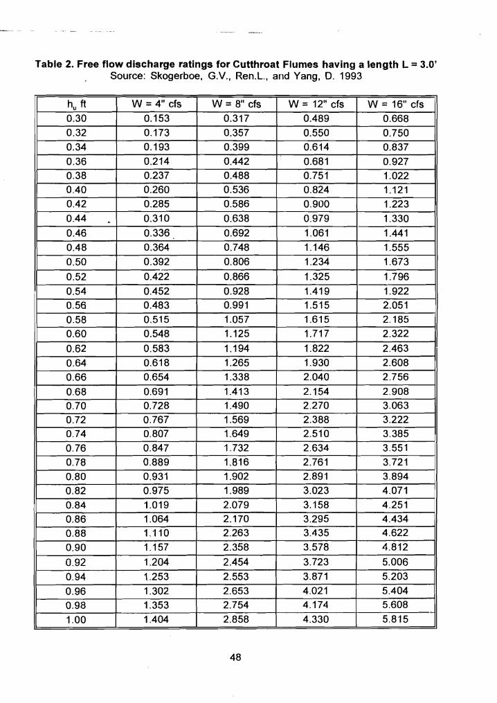
Free flow. The most useful method for representing the free flow discharge
equation is in a free flow discharge rating table. Then, an individual can measure the
upstream flow depth, hu ' in the Cutthroat Flume and then find the corresponding free
flow disch~rge rate, Q" in the rating table as shown in Table 2 for the Cutthroat Flumes
having a flume length, L, of 3 feet.
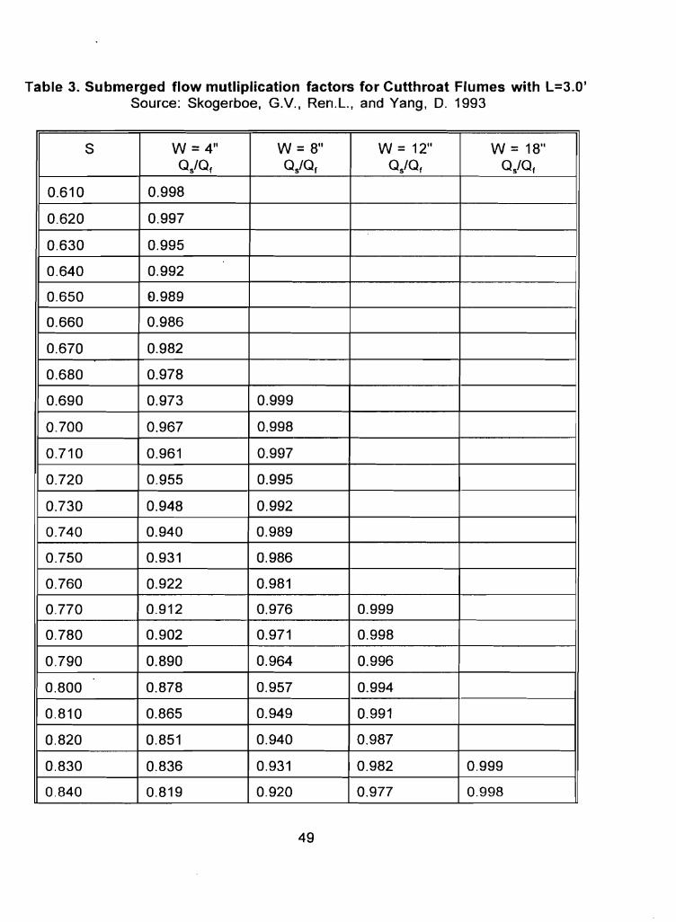
Submerged flow. A technique for representing a submerged flow discharge
rating table is to use a factor that has a unique value for each value of the
submergence, S. This can be done by calculating the ratio of the submerged flow
discharge rate by the free flow discharge, Q/Of:
o, Cs(hu-IJJn, 1
(18) 0, (-logSt' C,h;'
Q s = Cs(1 -st' (19) Q, C~ -logS)ns
Values of the submergence, S, greater than the transition submergence, S" are
substituted into Equation 19 and the submerged flow multiplication factor, a/Qt.
calculated. The results are listed in Table 3 for flumes having a length of 3 feet. Note
46
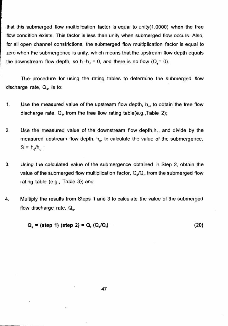
that this submerged flow multiplication factor is equal to unity(1.0000) when the free
flow condition exists. This factor is less than unity when submerged flow occurs. Also,
for all open channel constrictions, the submerged flow rnuttiplicafion factor is equal to
zero when the submergence is unity. which means that the upstream flow depth equals
the downstream flow depth, so hu-hd = O. and there is no flow (Q = 0).s
The procedure for using the rating tables to determine the SUbmerged flow
discharge rate, Qs' is to:
1. Use the measured value of the upstream flow depth, hut to obtain the free flow
discharge rate, Qf' from the free flow rating table(e.g.,Table 2);
2. Use the measured value of the downstream flow depth.h., and divide by the
measured upstream flow depth, hu' to calculate the value of the SUbmergence.
S =hihu ;
3. Using the calculated value of the submergence obtained in Step 2. obtain the
value of the submerged flow multiplication factor, Q/Q" from the submerged flow
rating table (e.g., Table 3); and
4. Multiply the results from Steps 1 and 3 to calculate the value of the submerged
flow discharge rate, Qs'
Qs = (step 1) (step 2) = Qf (Qs/Qf ) (20)
47
·. t·
Table 2. Free flow discharge ratings for Cutthroat Flumes having a length L = 3.0' Source: Skogerboe, G.v., Ren.L., and Yang, D. 1993
h, ft W =4" cfs W =8" cfs W =12" cfs W =16" cfs 0.30 0.153 0.317 0.489 0.668 0.32 0.173 0.357 0.550 0.750
0.34 0.193 0.399 0.614 0.837
0.36 0.214 0.442 0.681 0.927 0.38 0.237 0.488 0.751 1.022 0.40 0.260 0.536 0.824 1.121 0.42 0.285 0.586 0.900 1.223
0.44 . 0.310 0.638 0.979 1.330
0.46 0.336 0.692 1.061 1.441
0.48 0.364 0.748 1.146 1.555
0.50 0.392 0.806 1.234 1.673
0.52 0.422 0.866 1.325 1.796
0.54 0.452 0.928 1.419 1.922
0.56 0.483 0.991 1.515 2.051
0.58 0.515 1.057 1.615 2.185
0.60 0.548 1.125 1.717 2.322
0.62 0.583 1.194 1.822 2.463
0.64 0.618 1.265 1.930 2.608
0.66 0.654 1.338 2.040 2.756
0.68 0.691 1.413 2.154 2.908
0.70 0.728 1.490 2.270 3.063
0.72 0.767 1.569 2.388 3.222
0.74 0.807 1.649 2.510 3.385
0.76 0.847 1.732 2.634 3.551
0.78 0.889 1.816 2.761 3.721
0.80 0.931 1.902 2.891 3.894
0.82 0.975 1.989 3.023 4.071
0.84 1.019 2.079 3.158 4.251
0.86 1.064 2.170 3.295 4.434
0.88 1.110 2.263 3.435 4.622
0.90 1.157 2.358 3.578 4.812
0.92 1.204 2.454 3.723 5.006
0.94 1.253 2.553 3.871 5.203
0.96 1.302 2.653 4.021 5.404
0.98 1.353 2.754 4.174 5.608
1.00 1.404 2.858 4.330 5.815
48
· .....: .. f. ...
Table 3. Submerged flow mutliplication factors for Cutthroat Flumes with L=3.0' Source: Skogerboe, G.V., Ren.L., and Yang, D. 1993
S W=4" a/Of
W= 8" a/Of
W = 12" as/Of
W = 18" a/Of
0.610 0.998
0.620 0.997
0.630 0.995
0.640 0.992
0.650 0.989
0.660 0.986
0.670 0.982
0.680 0.978
0.690 0.973 0.999
0.700 0.967 0.998
0.710 0.961 0.997
0.720 0.955 0.995
0.730 0.948 0.992
0.740 0.940 0.989
0.750 0.931 0.986
0.760 0.922 0.981
0.770 0.912 0.976 0.999
0.780 0.902 0.971 0.998
0.790 0.890 0.964 0.996
0.800 0.878 0.957 0.994
0.810 0.865 0.949 0.991
0.820 0.851 0.940 0.987
0.830 0.836 0.931 0.982 0.999
0.840 0.819 0.920 0.977 0.998
49
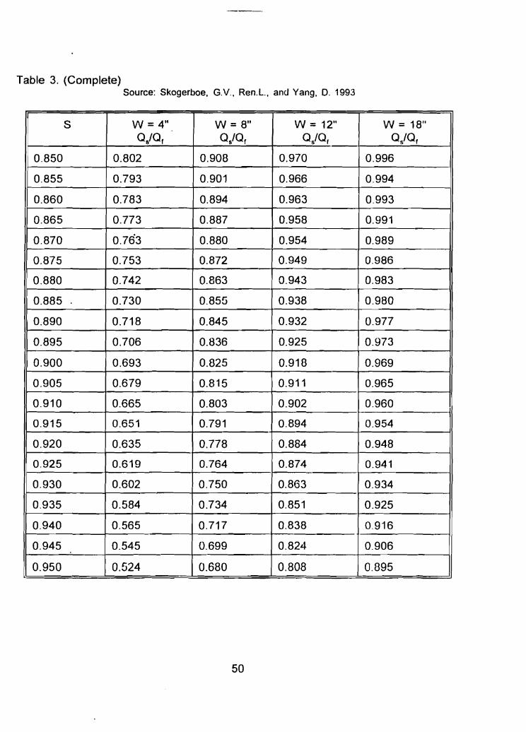
Table 3. (Complete) Source: Skogerboe, G.v., Ren.L., and Yang, D. 1993
S W=4" QiQr
W= 8" QiQr
W = 12" QiQf
W = 18" QiQr
0.850 0.802 0.908 0.970 0.996
0.855 0.793 0.901 0.966 0.994
0.860 0.783 0.894 0.963 0.993
0.865 0.773 0.887 0.958 0.991
0.870 0.763 0.880 0.954 0.989
0.875 0.753 0.872 0.949 0.986
0.880 0.742 0.863 0.943 0.983
0.885 0.730 0.855 0.938 0.980
0.890 0.718 0.845 0.932 0.977
0.895 0.706 0.836 0.925 0.973
0.900 0.693 0.825 0.918 0.969
0.905 0.679 0.815 0.911 0.965
0.910 0.665 0.803 0.902 0.960
0.915 0.651 0.791 0.894 -0.954
0.920 0.635 0.778 0.884 0.948
0.925 0.619 0.764 0.874 0.941
0.930 0.602 0.750 0.863 0.934
0.935 0.584 0.734 0.851 0.925
0.940 0.565 0.717 0.838 0.916
0.945 0.545 0.699 0.824 0.906
0.950 0.524 0.680 0.808 0.895
50
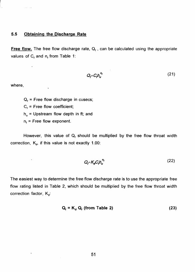
5.5 Obtaining the Discharge Rate
Free flow. The free flow discharge rate, O. ' can be calculated using the appropriate
values of C, and n, from Table 1:
(21)
where,
O, = Free flow discharge in cusecs;
C, = Free flow coefficient;
hu = Upstream flow depth in ft; and
n, = Free flow exponent.
However, this value of O, should be multiplied by the free flow throat width
correction, ~, if this value is not exactly 1.00:
(22)
The easiest way to determine the free flow discharge rate is to use the appropriate free
flow rating listed in Table 2, which should be multiplied by the free flow throat width
correction factor, Klr:
Q, =Ktf Qf (from Table 2) (23)
51
-----------.
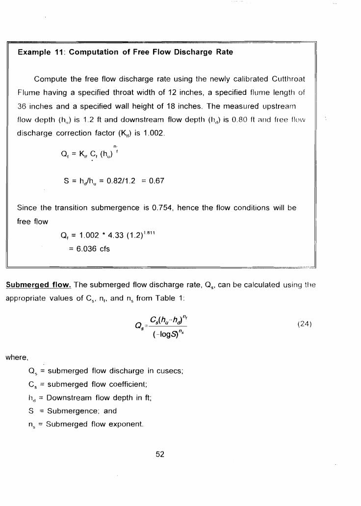
Example 11: Computation of Free Flow Discharge Rate
Compute the free flow discharge rate using the newly calibrated Cutthroat
Flume having a specified throat width of 12 inches, a specified flume length of
36 inches and a specified wall height of 18 inches. The measured upstream
flow depth (h,,) is 1.2 ft and downstream flow depth (h'l) is 0.80 ft and free Ilow
discharge correction factor (Klr) is 1.002.
n-
O, = KIf C, (hu) f
S = hihu =0.82/1.2 =0.67
Since the transition submergence is 0.754, hence the flow conditions will be
free flow
O, =1.002 * 4.33 (1.2) 1811
=6.036 cfs
l.!:=========J SUbmerged flow. The submerged flow discharge rate, Qs' can be calculated using the
appropriate values of C ' n., and n from Table 1:s s
C (h -h \II(Q= 5 u dl (24 )
5
(-logSts
where,
O, = submerged flow discharge in cusecs;
C, = submerged flow coefficient;
hrj = Downstream flow depth in ft;
S = Submergence; and
ns = SUbmerged flow exponent.
52
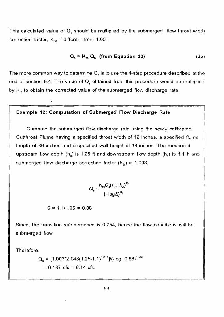
This calculated value of O, should be multiplied by the submerged flow throat width
correction factor, Kts l if different from 1.00:
Qs = K ts Q s (from Equation 20) (25)
The more common way to determine O, is to use the 4-step procedure described at the
end of section 5.4. The value of O, obtained from this procedure would be multiplied
by Kts to obtain the corrected value of the submerged flow discharge rate.
Example 12: Computation of Submerged Flow Discharge Rate
Compute the submerged flow discharge rate using the newly calibrated
Cutthroat Flume having a specified throat width of 12 inches, a specified flume
length of 36 inches and a specified wall height of 18 inches. The measured
upstream flow depth (h) is 1.25 ft and downstream flow depth (hd) is 1.1 11 and
submerged flow discharge correction factor (Kts) is 1.003.
S == 1.1/1.25 =0.88
Since, the transition submergence is 0.754, hence the flow conditions will be
submerged flow
Therefore,
o, = [1.003*2.048(1.25-1.1)1811]/(-log 0.88)1567
== 6. 137 cfs == 6.14 cfs.
53
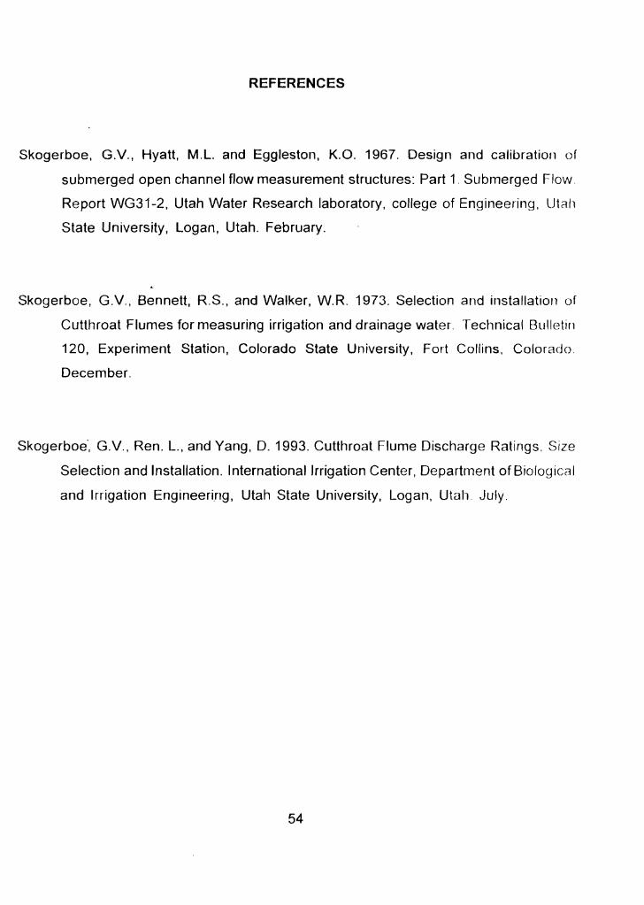
REFERENCES
Skogerboe, GV., Hyatt, M.L. and Eggleston, K.G. 1967. Design and calibration of
submerged open channel flow measurement structures: Part 1. Submerged Flow.
Report WG31-2, Utah Water Research laboratory, college of Engineering, Utah
State University, Logan, Utah. February.
Skogerboe, GV., Bennett, R.S., and Walker, W.R. 1973. Selection and installation of
Cutthroat Flumes for measuring irrigation and drainage water Technical Bulletin
120, Experiment Station, Colorado State University, Fort Collins, Colorado.
December.
Skoqerboe, G.v., Ren. L., and Yang, D. 1993. Cutthroat Flume Discharge Ratings. Size
Selection and Installation. International Irrigation Center, Department of Biological
and Irrigation Engineering, Utah State University, Logan, Utah. JUly.
54
ANNEXURE
FORMS FOR RECORDING THE MEASUREMENTS OF
THE CUTTHROAT FLUME DIMENSIONS
55
Flume size
Flume number
Field location
Date
Sheet 1 of 5
FORMS FOR RECORDING THE MEASUREMENTS OF
THE CUTTHROAT FLUME DIMENSIONS
"
Equations used:
W,= _
w.:»:
W s == ---~---------N
vv, = _K,S
1. THROAT WIDTH
Width of Throat Section for Free Flow (Wf )
W',2 W 3 W6 Total Average Wsp Kif Remarks
Width of Throat Section for Submerged Flow (WJ
W"2 W 3 W6 W g W 12 Total Average Wsp Ku Remarks
Observer Checked by:
56
Sheet 2 of 5
FORMS FOR RECORDING THE MEASUREMENTS OF
THE CUTTHROAT FLUME DIMENSIONS
Equations used: Flume size
Flume number
Field location
Date
2. PIEZOMETER TAPS
UPSTREAM PIEZOMETER TAP
(L,,)meas (LJs p =2L19 Difference (%)
Remarks
DOWNSTREAM PIEZOMETER TAP
Difference Remarks(L..lsl' = 5L19(Lr1) !fl,!a<;
(%)
Observer: Checked by:
57
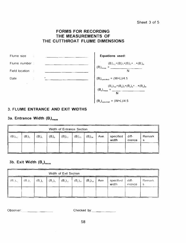
Sheet 3 of 5
FORMS FOR RECORDING THE MEASUREMENTS OF
THE CUTTHROAT FLUME DIMENSIONS
I
Flume size
Flume number
Field location
Date
3. FLUME ENTRANCE AND EXIT WIDTHS
3a. Entrance Width (BJmeas
I Width of Entrance Section
(B.) 11/ (B')3 (B,)/; (B,)9 (B,) 1? (B,) I~, (B,)1A Ave. specified width
difference
Remark s
3b. Exit Width (Bo)meas
Equations used:
(B')II~+(B,L+(B,)l'+ .. +(B,)II (B,)onoas = _
N
(B,)spac'fled = (W+L)/45
(Bo)1/~+( Bah+( BO)6+ ... +( BO)II
(Bo)meas =--------N
(Bo)5P~c'f,ed =(W+L)/4.5
Width of Exit Section
(fJk (B.) 1 (B,,)., (B o),) (Bol1:' (B.,)I" (Bo) In Ave specified width
eMf-«renee
r~elllil' k
S -I--.
Observer _ Checked by: _
58
--
Sheet '1 of 5
FORMS FOR RECORDING THE MEASUREMENTS OF
THE CUTTHROAT FLUME DIMENSIONS
Flume size
f lume (lumber
Field location
Date
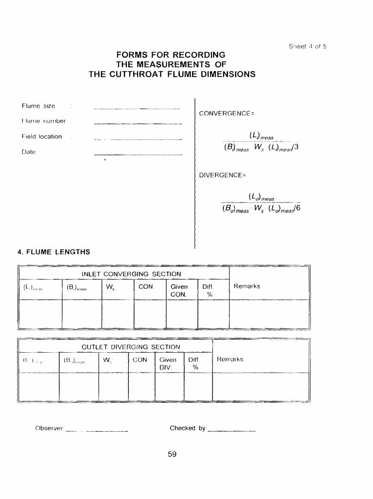
CONVERGENCE=
(L,)meas -_._--~--------_._----- ~--_._-
(B j) meas w:< (L) me'1/3
DIVERGENCE:::
(Lo)meas ------_.~-------- --~-
(Bo)meas - Ws -(LJmeaJ6
4. FLUME LENGTHS
INLET CONVERGING SECTION
Remarks
-------
-,
(L,),nc'", (B)rneas W5
CON,
f--
Given CON,
Diff, o/"
OUTLET DIVERGING SECTION
Hemal ks(I )"", (8,,)""'''5 W, CON. Given DIV,
Diff %
J Observer Checked by: _
59
--------
Sheet 5 of 5
FORMS FOR RECORDING THE MEASUREMENTS OF
THE CUTTHROAT FLUME DIMENSIONS
Flume size
Flume number
Field location
Date
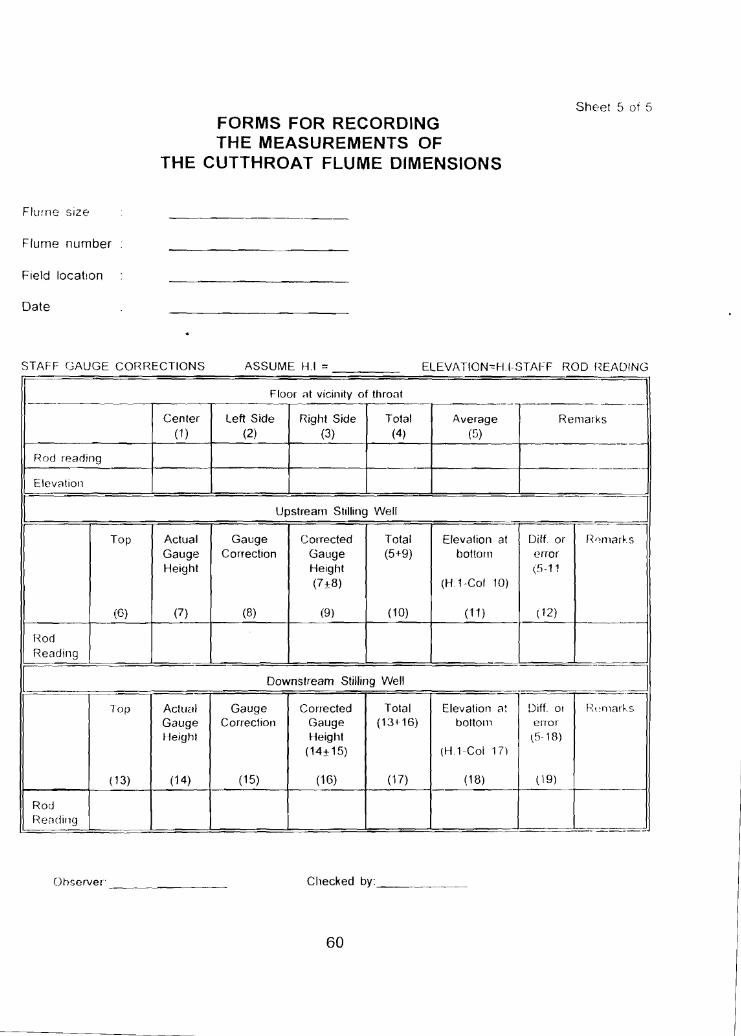
STAFF C;AUGE c CORRECTIONS ASSUME HI = ELEVATIONc:H I STAFF . -, ROD r~EADING
Floor at vicinity of throat -~ -·--r------
Center Left Side TotalRight Side Average Remarks (2) (4)(1) (3) (5)
Rod reading -~_._-,--
Elevation
[ Upstream Stilling Well
Top Actual Gauge Corrected Diff orTotal Elevation at r~',rnarks
error Height
Correction (5+9) bottomGauge Gauge Height (5-11 (7 ±8) (H 1-Col 10)
(8) (10) (12)
Rod Reading
[ Downstream Stilling Well
(6) (7) (9) (11 )
.:=J f'\(~1l1arksTolalTop Actual Gauge Corrected Elevation at I ~Diff 0'
(13+16)Correction Gauge bottom error Height Gauge
(518) (14±15) Height
(H1-Coi 1()
( 19)
Rod Reilcling
(15) (17) (18)(14) (16)( 13)
-
J
""~
Ohserver _ Checked by: _
60
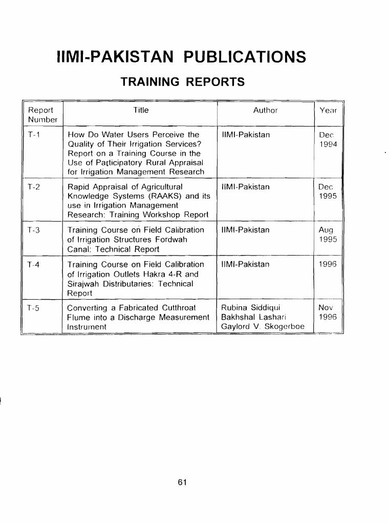
IIMI-PAKISTAN PUBLICATIONS
TRAINING REPORTS
Report Number
Title Author Year
-
T-1 How Do Water Users Perceive the 11M I-Pakistan Dec Quality of Their Irrigation Services? Report on a Training Course in the Use of Participatory Rural Appraisal for Irrigation Management Research
1994
T-2 Rapid Appraisal of Agricultural Knowledge Systems (RAAKS) and its use in Irrigation Management Research: Training Workshop Report
IIMI-Pakistan Dec 1995
- T-3 Training Course on Field Calibration
of Irrigation Structures Fordwah Canal: Technical Report
11M I-Pakistan Aug 1995
T-4
T-5
Training Course on Field Calibration of Irrigation Outlets Hakra 4-R and Sirajwah Distributaries: Technical Report
Converting a Fabricated Cutthroat Flume into a Discharge Measurement Instrument
IIMI-Pakistan 1996
----~ Rubina Siddiqui Nov Bakhshal Lashari 1996 Gaylord V. Skogerboe . _.=
61