Customised Solutions - Incledon Pumps/9d Grundfos CR Solutions.pdf · Use low NPSH pump to reduce...
21
GRUNDFOS INDUSTRY Customised Solutions
Transcript of Customised Solutions - Incledon Pumps/9d Grundfos CR Solutions.pdf · Use low NPSH pump to reduce...
GRUNDFOS INDUSTRY
Customised Solutions
32
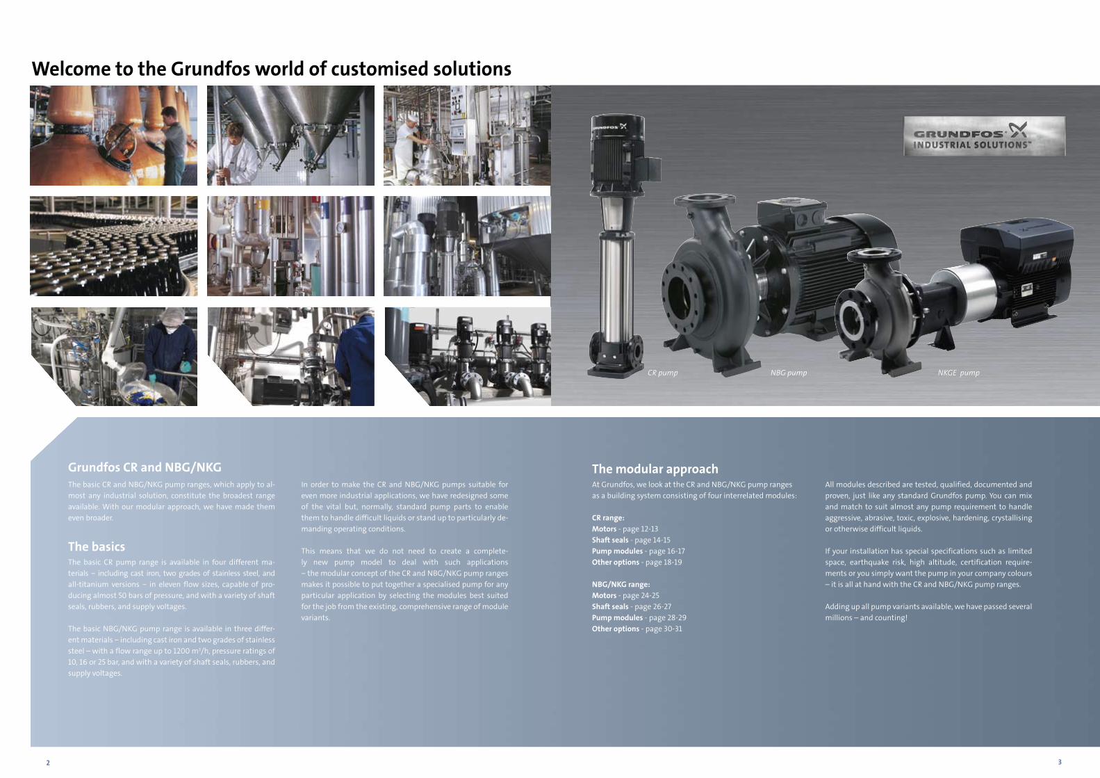
Grundfos CR and NBG/NKG The basic CR and NBG/NKG pump ranges, which apply to al-most any industrial solution, constitute the broadest range available. With our modular approach, we have made them even broader.
The basicsThe basic CR pump range is available in four different ma- terials − including cast iron, two grades of stainless steel, and all-titanium versions − in eleven flow sizes, capable of pro- ducing almost 50 bars of pressure, and with a variety of shaft seals, rubbers, and supply voltages.
The basic NBG/NKG pump range is available in three differ-ent materials − including cast iron and two grades of stainless steel – with a flow range up to 1200 m3/h, pressure ratings of 10, 16 or 25 bar, and with a variety of shaft seals, rubbers, and supply voltages.
In order to make the CR and NBG/NKG pumps suitable for even more industrial applications, we have redesigned some of the vital but, normally, standard pump parts to enable them to handle difficult liquids or stand up to particularly de-manding operating conditions.
This means that we do not need to create a complete-ly new pump model to deal with such applications − the modular concept of the CR and NBG/NKG pump ranges makes it possible to put together a specialised pump for any particular application by selecting the modules best suited for the job from the existing, comprehensive range of module variants.
The modular approachAt Grundfos, we look at the CR and NBG/NKG pump ranges as a building system consisting of four interrelated modules:
CR range:Motors - page 12-13Shaft seals - page 14-15Pump modules - page 16-17Other options - page 18-19
NBG/NKG range:Motors - page 24-25Shaft seals - page 26-27Pump modules - page 28-29Other options - page 30-31
All modules described are tested, qualified, documented and proven, just like any standard Grundfos pump. You can mix and match to suit almost any pump requirement to handle aggressive, abrasive, toxic, explosive, hardening, crystallising or otherwise difficult liquids.
If your installation has special specifications such as limited space, earthquake risk, high altitude, certification require-ments or you simply want the pump in your company colours – it is all at hand with the CR and NBG/NKG pump ranges.
Adding up all pump variants available, we have passed several millions – and counting!
Welcome to the Grundfos world of customised solutions
CR pump NBG pump NKGE pump
4 5
Situation Consequence Solution See page
High temperatureShaft seal destroyed Special Grundfos shaft seal designed to
handle hot liquids up to 160°C26 27
Bearing life reduced Monitoring of bearing temperatures 29
Fluctuating steam demand Pump performance must adapt Use NBGE/NKGE speed controlled pumps 24
Thermal oils Shaft seal and rubbers destroyed Special shaft seal designed to handle oil up to 220°C
26 27
Varying frequencies and voltages around the world
Need for different frequencies and voltages
Choose among our wide range of motors with different frequencies and voltages 25
NBG/NKG range• Filtration• Membrane filtration/Feed pump• Pressure boosting• Washing and cleaning• Industrial processes
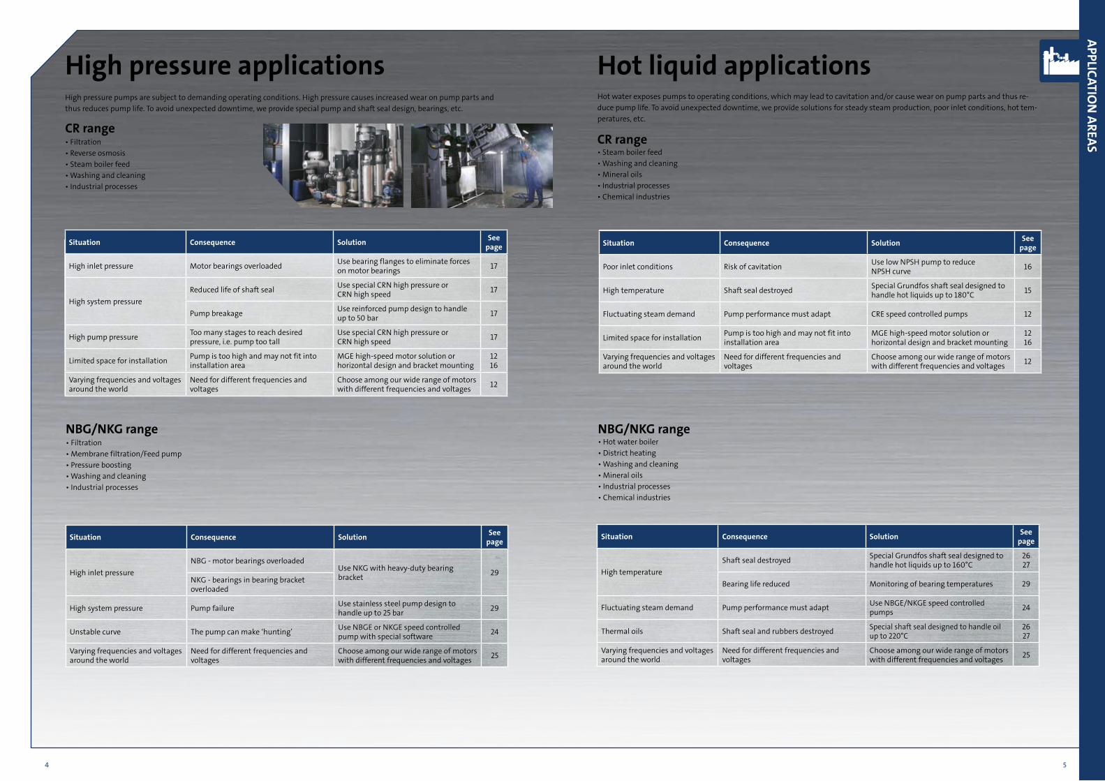
Hot liquid applicationsHot water exposes pumps to operating conditions, which may lead to cavitation and/or cause wear on pump parts and thus re-duce pump life. To avoid unexpected downtime, we provide solutions for steady steam production, poor inlet conditions, hot tem-peratures, etc.
CR range • Steam boiler feed• Washing and cleaning• Mineral oils• Industrial processes• Chemical industries
Situation Consequence Solution See page
High inlet pressure Motor bearings overloaded Use bearing flanges to eliminate forces on motor bearings 17
High system pressureReduced life of shaft seal Use special CRN high pressure or
CRN high speed 17
Pump breakage Use reinforced pump design to handle up to 50 bar 17
High pump pressure Too many stages to reach desired pressure, i.e. pump too tall
Use special CRN high pressure or CRN high speed 17
Limited space for installation Pump is too high and may not fit into installation area
MGE high-speed motor solution or horizontal design and bracket mounting
1216
Varying frequencies and voltages around the world
Need for different frequencies and voltages
Choose among our wide range of motors with different frequencies and voltages 12
Situation Consequence Solution See page
High inlet pressureNBG - motor bearings overloaded
Use NKG with heavy-duty bearing bracket 29
NKG - bearings in bearing bracket overloaded
High system pressure Pump failure Use stainless steel pump design to handle up to 25 bar 29
Unstable curve The pump can make ‘hunting’ Use NBGE or NKGE speed controlled pump with special software 24
Varying frequencies and voltages around the world
Need for different frequencies and voltages
Choose among our wide range of motors with different frequencies and voltages 25
Situation Consequence Solution See page
Poor inlet conditions Risk of cavitation Use low NPSH pump to reduce NPSH curve 16
High temperature Shaft seal destroyed Special Grundfos shaft seal designed to handle hot liquids up to 180°C 15
Fluctuating steam demand Pump performance must adapt CRE speed controlled pumps 12
Limited space for installation Pump is too high and may not fit into installation area
MGE high-speed motor solution or horizontal design and bracket mounting
1216
Varying frequencies and voltages around the world
Need for different frequencies and voltages
Choose among our wide range of motors with different frequencies and voltages 12
NBG/NKG range • Hot water boiler • District heating • Washing and cleaning • Mineral oils • Industrial processes • Chemical industries
APPLICATION
AREAS
High pressure applicationsHigh pressure pumps are subject to demanding operating conditions. High pressure causes increased wear on pump parts and thus reduces pump life. To avoid unexpected downtime, we provide special pump and shaft seal design, bearings, etc.
CR range• Filtration • Reverse osmosis• Steam boiler feed• Washing and cleaning• Industrial processes
6 7
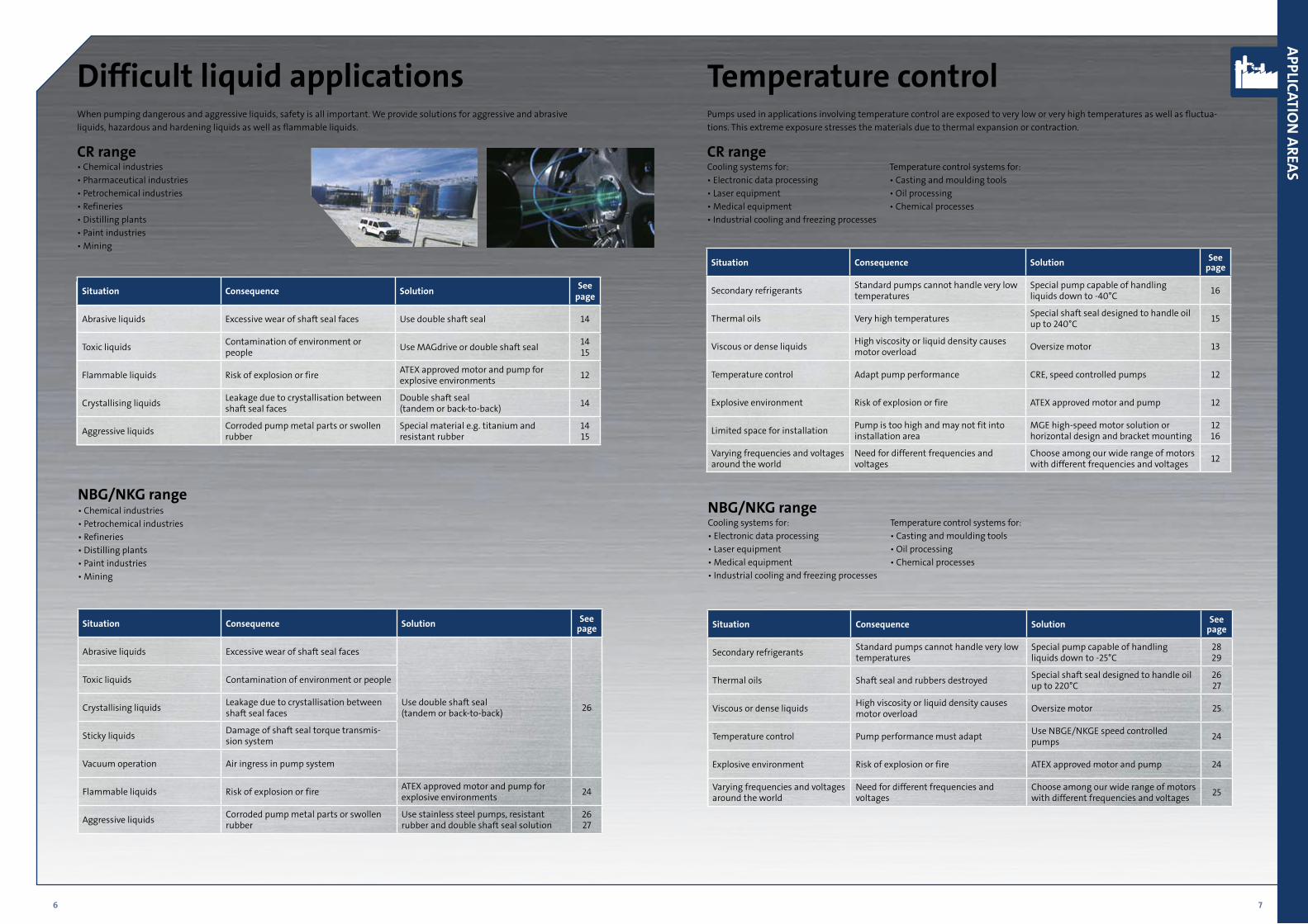
Difficult liquid applicationsWhen pumping dangerous and aggressive liquids, safety is all important. We provide solutions for aggressive and abrasive liquids, hazardous and hardening liquids as well as flammable liquids.
CR range• Chemical industries• Pharmaceutical industries• Petrochemical industries• Refineries • Distilling plants• Paint industries• Mining
NBG/NKG range • Chemical industries • Petrochemical industries • Refineries • Distilling plants • Paint industries • Mining
Temperature controlPumps used in applications involving temperature control are exposed to very low or very high temperatures as well as fluctua-tions. This extreme exposure stresses the materials due to thermal expansion or contraction.
CR rangeCooling systems for: Temperature control systems for:• Electronic data processing • Casting and moulding tools• Laser equipment • Oil processing• Medical equipment • Chemical processes• Industrial cooling and freezing processes
NBG/NKG range Cooling systems for: Temperature control systems for:• Electronic data processing • Casting and moulding tools• Laser equipment • Oil processing• Medical equipment • Chemical processes• Industrial cooling and freezing processes
Situation Consequence Solution See page
Abrasive liquids Excessive wear of shaft seal faces Use double shaft seal 14
Toxic liquids Contamination of environment or people Use MAGdrive or double shaft seal 14
15
Flammable liquids Risk of explosion or fire ATEX approved motor and pump for explosive environments 12
Crystallising liquids Leakage due to crystallisation between shaft seal faces
Double shaft seal (tandem or back-to-back) 14
Aggressive liquids Corroded pump metal parts or swollen rubber
Special material e.g. titanium and resistant rubber
14 15
Situation Consequence Solution See page
Secondary refrigerants Standard pumps cannot handle very low temperatures
Special pump capable of handling liquids down to -40°C 16
Thermal oils Very high temperatures Special shaft seal designed to handle oil up to 240°C 15
Viscous or dense liquids High viscosity or liquid density causes motor overload Oversize motor 13
Temperature control Adapt pump performance CRE, speed controlled pumps 12
Explosive environment Risk of explosion or fire ATEX approved motor and pump 12
Limited space for installation Pump is too high and may not fit into installation area
MGE high-speed motor solution or horizontal design and bracket mounting
1216
Varying frequencies and voltages around the world
Need for different frequencies and voltages
Choose among our wide range of motors with different frequencies and voltages 12
Situation Consequence Solution See page
Secondary refrigerants Standard pumps cannot handle very low temperatures
Special pump capable of handling liquids down to -25°C
28 29
Thermal oils Shaft seal and rubbers destroyed Special shaft seal designed to handle oil up to 220°C
26 27
Viscous or dense liquids High viscosity or liquid density causes motor overload Oversize motor 25
Temperature control Pump performance must adapt Use NBGE/NKGE speed controlled pumps 24
Explosive environment Risk of explosion or fire ATEX approved motor and pump 24
Varying frequencies and voltages around the world
Need for different frequencies and voltages
Choose among our wide range of motors with different frequencies and voltages 25
APPLICATION
AREAS
Situation Consequence Solution See page
Abrasive liquids Excessive wear of shaft seal faces
Use double shaft seal(tandem or back-to-back) 26
Toxic liquids Contamination of environment or people
Crystallising liquids Leakage due to crystallisation between shaft seal faces
Sticky liquids Damage of shaft seal torque transmis-sion system
Vacuum operation Air ingress in pump system
Flammable liquids Risk of explosion or fire ATEX approved motor and pump for explosive environments 24
Aggressive liquids Corroded pump metal parts or swollen rubber
Use stainless steel pumps, resistant rubber and double shaft seal solution
26 27
8 9
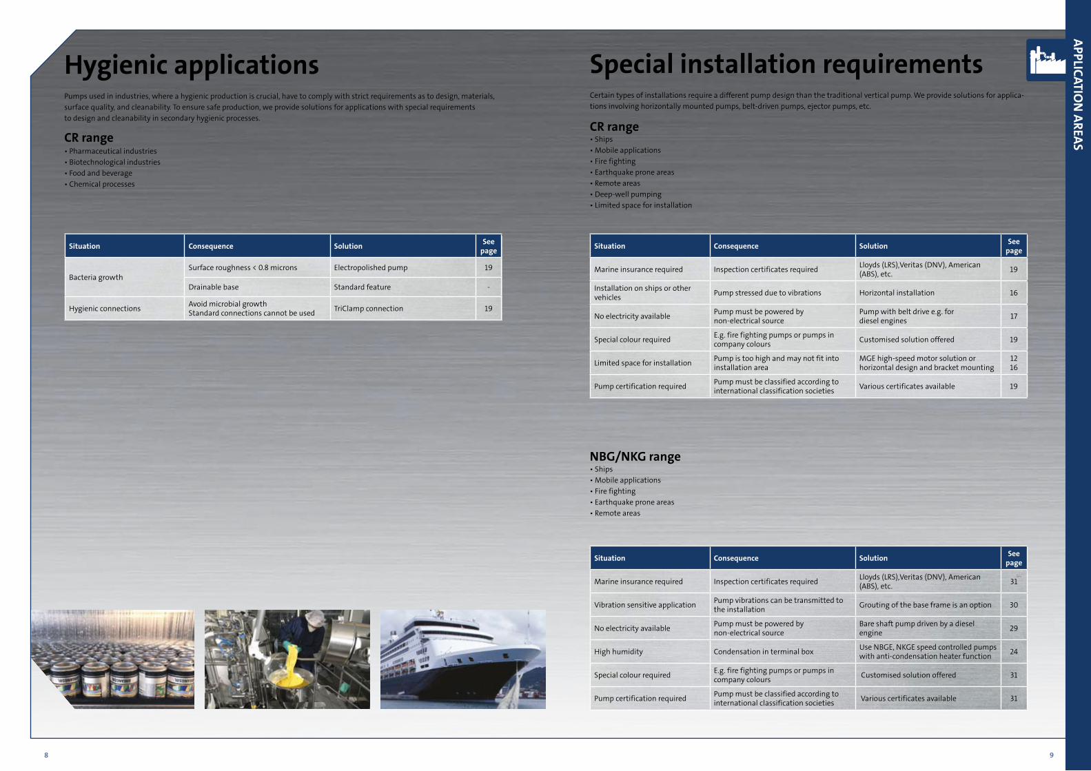
Hygienic applicationsPumps used in industries, where a hygienic production is crucial, have to comply with strict requirements as to design, materials, surface quality, and cleanability. To ensure safe production, we provide solutions for applications with special requirements to design and cleanability in secondary hygienic processes.
CR range• Pharmaceutical industries• Biotechnological industries• Food and beverage • Chemical processes
Special installation requirementsCertain types of installations require a different pump design than the traditional vertical pump. We provide solutions for applica-tions involving horizontally mounted pumps, belt-driven pumps, ejector pumps, etc.
CR range • Ships• Mobile applications• Fire fighting• Earthquake prone areas• Remote areas• Deep-well pumping• Limited space for installation
Situation Consequence Solution See page
Bacteria growthSurface roughness < 0.8 microns Electropolished pump 19
Drainable base Standard feature -
Hygienic connections Avoid microbial growth Standard connections cannot be used TriClamp connection 19
Situation Consequence Solution See page
Marine insurance required Inspection certificates required Lloyds (LRS),Veritas (DNV), American (ABS), etc. 19
Installation on ships or other vehicles Pump stressed due to vibrations Horizontal installation 16
No electricity available Pump must be powered by non-electrical source
Pump with belt drive e.g. for diesel engines 17
Special colour required E.g. fire fighting pumps or pumps in company colours Customised solution offered 19
Limited space for installation Pump is too high and may not fit into installation area
MGE high-speed motor solution or horizontal design and bracket mounting
1216
Pump certification required Pump must be classified according to international classification societies Various certificates available 19
NBG/NKG range • Ships• Mobile applications• Fire fighting• Earthquake prone areas• Remote areas
Situation Consequence Solution See page
Marine insurance required Inspection certificates required Lloyds (LRS),Veritas (DNV), American(ABS), etc. 31
Vibration sensitive application Pump vibrations can be transmitted to the installation Grouting of the base frame is an option 30
No electricity available Pump must be powered by non-electrical source
Bare shaft pump driven by a diesel engine 29
High humidity Condensation in terminal box Use NBGE, NKGE speed controlled pumps with anti-condensation heater function 24
Special colour required E.g. fire fighting pumps or pumps in company colours Customised solution offered 31
Pump certification required Pump must be classified according to international classification societies Various certificates available 31
APPLICATION
AREAS
10 11
CR/CRI/CRN/CRT – M
ULTISTAG
E CENTRIFU
GAL PU
MP
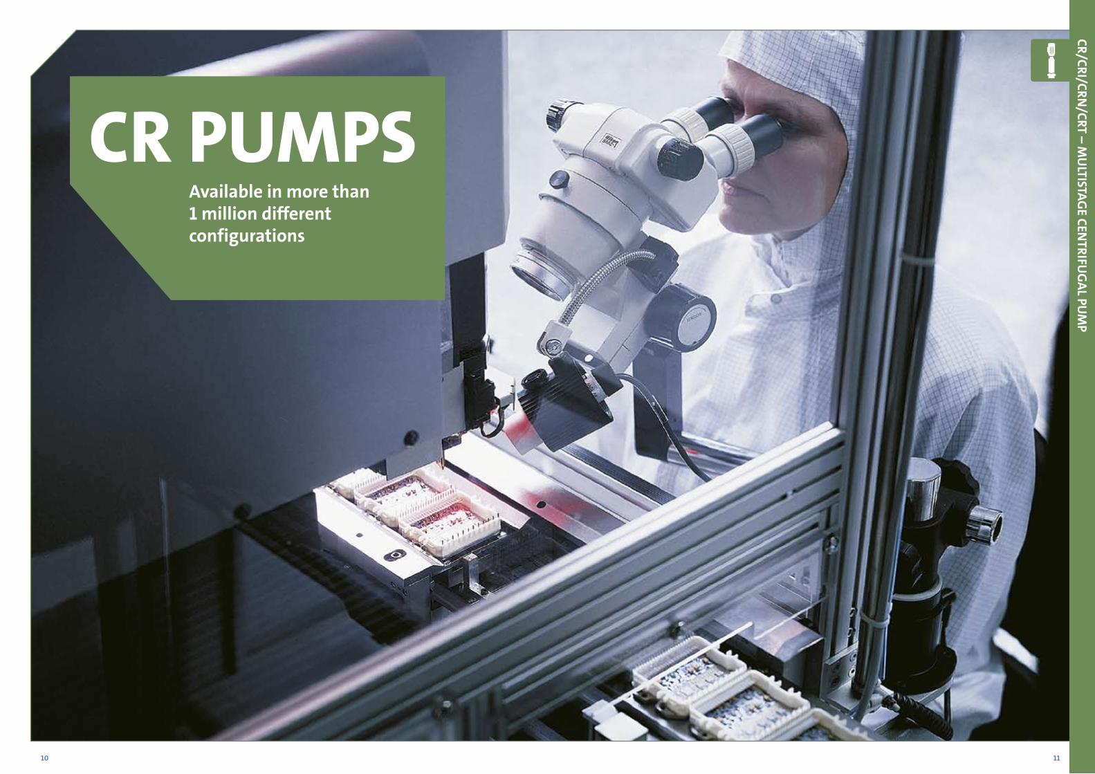
CR PUMPSAvailable in more than 1 million different configurations
12 13
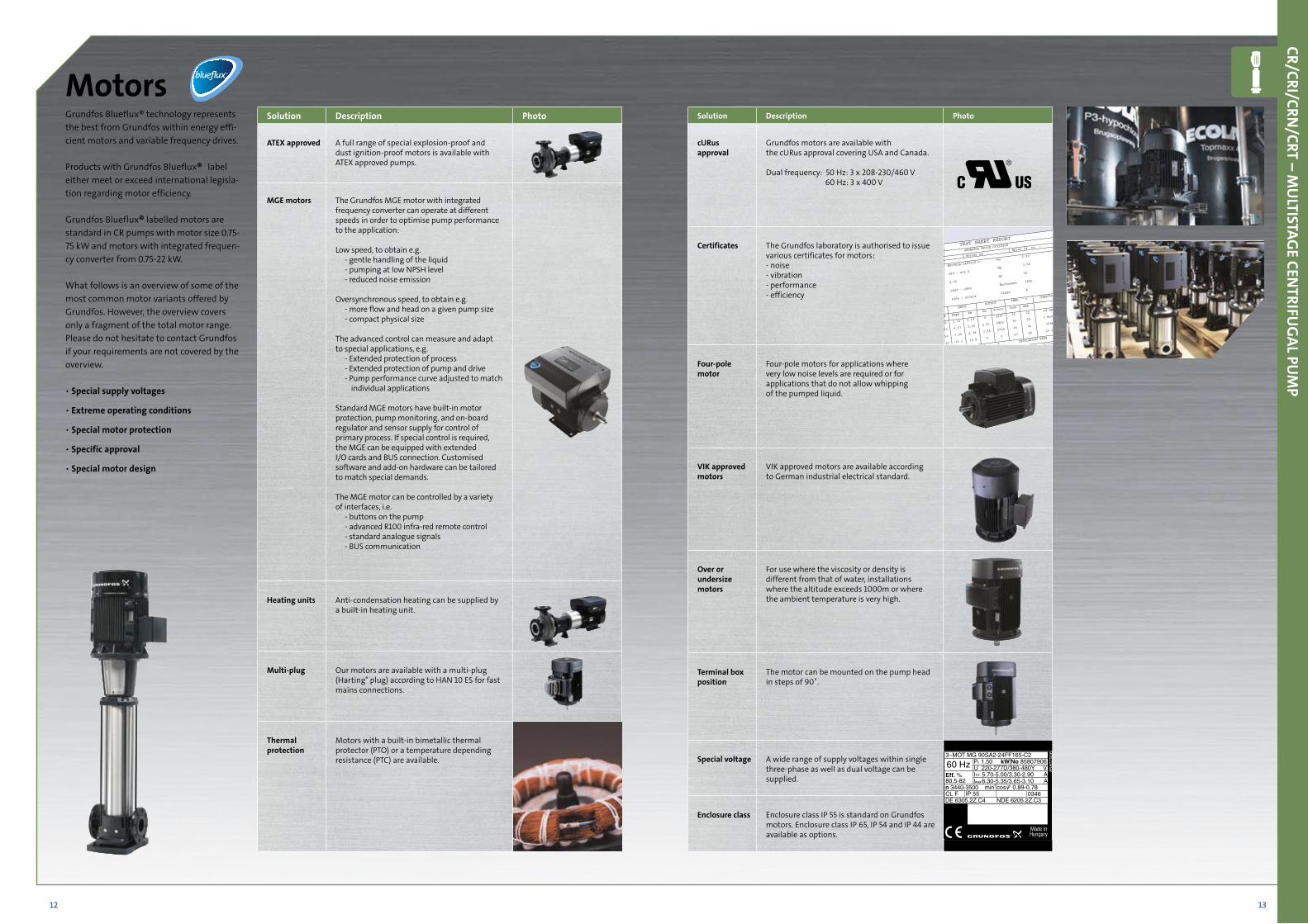
Grundfos Blueflux® technology represents the best from Grundfos within energy effi-cient motors and variable frequency drives.
Products with Grundfos Blueflux® label either meet or exceed international legisla-tion regarding motor efficiency.
Grundfos Blueflux® labelled motors are standard in CR pumps with motor size 0.75-75 kW and motors with integrated frequen-cy converter from 0.75-22 kW.
What follows is an overview of some of the most common motor variants offered by Grundfos. However, the overview covers only a fragment of the total motor range. Please do not hesitate to contact Grundfos if your requirements are not covered by the overview.
• Special supply voltages
• Extreme operating conditions
• Special motor protection
• Specific approval
• Special motor design
MotorsSolution Description Photo
ATEX approved A full range of special explosion-proof and dust ignition-proof motors is available with ATEX approved pumps.
MGE motors The Grundfos MGE motor with integrated frequency converter can operate at different speeds in order to optimise pump performance to the application:
Low speed, to obtain e.g.- gentle handling of the liquid- pumping at low NPSH level- reduced noise emission
Oversynchronous speed, to obtain e.g.- more flow and head on a given pump size- compact physical size
The advanced control can measure and adapt to special applications, e.g.
- Extended protection of process- Extended protection of pump and drive- Pump performance curve adjusted to match
individual applications
Standard MGE motors have built-in motor protection, pump monitoring, and on-board regulator and sensor supply for control of primary process. If special control is required, the MGE can be equipped with extended I/O cards and BUS connection. Customised software and add-on hardware can be tailored to match special demands.
The MGE motor can be controlled by a variety of interfaces, i.e.
- buttons on the pump- advanced R100 infra-red remote control- standard analogue signals- BUS communication
Heating units Anti-condensation heating can be supplied by a built-in heating unit.
Multi-plug Our motors are available with a multi-plug (Harting® plug) according to HAN 10 ES for fast mains connections.
Thermal protection
Motors with a built-in bimetallic thermal protector (PTO) or a temperature depending resistance (PTC) are available.
Solution Description Photo
cURus approval
Grundfos motors are available with the cURus approval covering USA and Canada.
Dual frequency: 50 Hz: 3 x 208-230/460 V 60 Hz: 3 x 400 V
Certificates The Grundfos laboratory is authorised to issue various certificates for motors:- noise- vibration- performance- efficiency
Four-pole motor
Four-pole motors for applications where very low noise levels are required or for applications that do not allow whipping of the pumped liquid.
VIK approved motors
VIK approved motors are available according to German industrial electrical standard.
Over or undersize motors
For use where the viscosity or density is different from that of water, installations where the altitude exceeds 1000m or where the ambient temperature is very high.
Terminal box position
The motor can be mounted on the pump head in steps of 90˚.
Special voltage A wide range of supply voltages within single three-phase as well as dual voltage can be supplied.
Enclosure class Enclosure class IP 55 is standard on Grundfos motors. Enclosure class IP 65, IP 54 and IP 44 are available as options.
CR/CRI/CRN/CRT – M
ULTISTAG
E CENTRIFU
GAL PU
MP
60 Hz3~MOT MG 90SA2-24FF165-C2
Eff. %80.5-82n 3440-3500 min-1
CL F IP 55 0346DE 6305.2Z.C4 NDE 6205.2Z.C3
P 1.50 kW2
U 220-277D/380-480Y VI 5.70-5.00/3.30-2.90 AI 6.30-5.35/3.65-3.10 A
cos 0.89-0.78
1/1
max
8580
7906
No 85807906
14 15
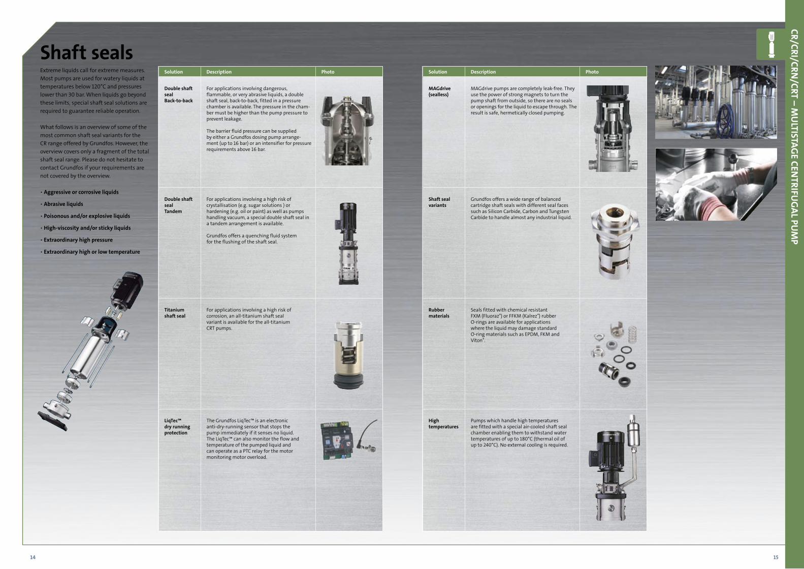
Extreme liquids call for extreme measures. Most pumps are used for watery liquids at temperatures below 120°C and pressures lower than 30 bar. When liquids go beyond these limits, special shaft seal solutions are required to guarantee reliable operation.
What follows is an overview of some of the most common shaft seal variants for the CR range offered by Grundfos. However, the overview covers only a fragment of the total shaft seal range. Please do not hesitate to contact Grundfos if your requirements are not covered by the overview.
• Aggressive or corrosive liquids
• Abrasive liquids
• Poisonous and/or explosive liquids
• High-viscosity and/or sticky liquids
• Extraordinary high pressure
• Extraordinary high or low temperature
Shaft seals
CR/CRI/CRN/CRT – M
ULTISTAG
E CENTRIFU
GAL PU
MP
Solution Description Photo
Double shaft sealBack-to-back
For applications involving dangerous, flammable, or very abrasive liquids, a double shaft seal, back-to-back, fitted in a pressure chamber is available. The pressure in the cham-ber must be higher than the pump pressure to prevent leakage.
The barrier fluid pressure can be supplied by either a Grundfos dosing pump arrange-ment (up to 16 bar) or an intensifier for pressure requirements above 16 bar.
Double shaft seal Tandem
For applications involving a high risk of crystallisation (e.g. sugar solutions ) or hardening (e.g. oil or paint) as well as pumps handling vacuum, a special double shaft seal in a tandem arrangement is available.
Grundfos offers a quenching fluid system for the flushing of the shaft seal.
Titanium shaft seal
For applications involving a high risk of corrosion, an all-titanium shaft seal variant is available for the all-titanium CRT pumps.
LiqTec™ dry running protection
The Grundfos LiqTec™ is an electronic anti-dry-running sensor that stops the pump immediately if it senses no liquid. The LiqTec™ can also monitor the flow and temperature of the pumped liquid and can operate as a PTC relay for the motor monitoring motor overload.
Solution Description Photo
MAGdrive (sealless)
MAGdrive pumps are completely leak-free. They use the power of strong magnets to turn the pump shaft from outside, so there are no seals or openings for the liquid to escape through. The result is safe, hermetically closed pumping.
Shaft seal variants
Grundfos offers a wide range of balanced cartridge shaft seals with different seal faces such as Silicon Carbide, Carbon and Tungsten Carbide to handle almost any industrial liquid.
Rubber materials
Seals fitted with chemical resistant FXM (Fluoraz®) or FFKM (Kalrez®) rubber O-rings are available for applications where the liquid may damage standard O-ring materials such as EPDM, FKM andViton®.
High temperatures
Pumps which handle high temperatures are fitted with a special air-cooled shaft seal chamber enabling them to withstand water temperatures of up to 180°C (thermal oil of up to 240°C). No external cooling is required.
16 17
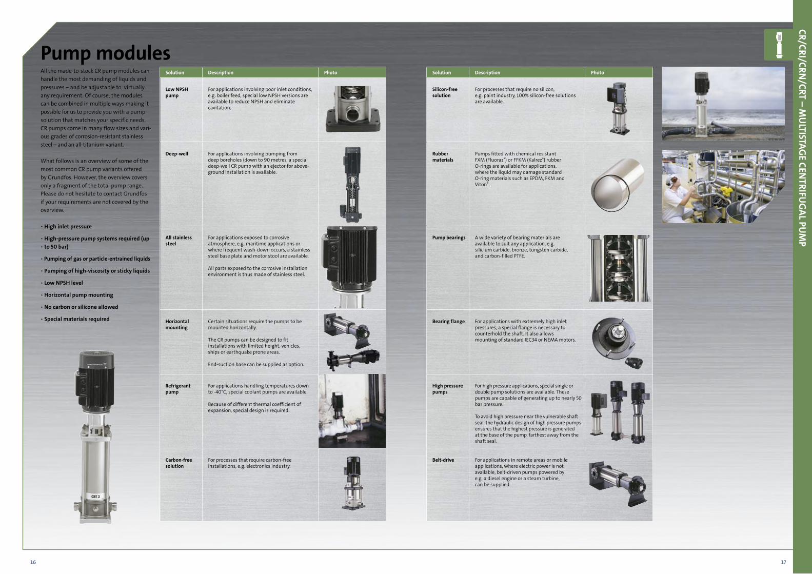
All the made-to-stock CR pump modules can handle the most demanding of liquids and pressures – and be adjustable to virtually any requirement. Of course, the modules can be combined in multiple ways making it possible for us to provide you with a pump solution that matches your specific needs. CR pumps come in many flow sizes and vari-ous grades of corrosion-resistant stainless steel – and an all-titanium variant.
What follows is an overview of some of the most common CR pump variants offered by Grundfos. However, the overview covers only a fragment of the total pump range. Please do not hesitate to contact Grundfos if your requirements are not covered by the overview.
• High inlet pressure
• High-pressure pump systems required (up • to 50 bar)
• Pumping of gas or particle-entrained liquids
• Pumping of high-viscosity or sticky liquids
• Low NPSH level
• Horizontal pump mounting
• No carbon or silicone allowed
• Special materials required
Pump modules
CR/CRI/CRN/CRT – M
ULTISTAG
E CENTRIFU
GAL PU
MP
Solution Description Photo
Low NPSHpump
For applications involving poor inlet conditions, e.g. boiler feed, special low NPSH versions are available to reduce NPSH and eliminate cavitation.
Deep-well For applications involving pumping from deep boreholes (down to 90 metres, a special deep-well CR pump with an ejector for above-ground installation is available.
All stainless steel
For applications exposed to corrosive atmosphere, e.g. maritime applications or where frequent wash-down occurs, a stainless steel base plate and motor stool are available.
All parts exposed to the corrosive installation environment is thus made of stainless steel.
Horizontal mounting
Certain situations require the pumps to be mounted horizontally.
The CR pumps can be designed to fit installations with limited height, vehicles, ships or earthquake prone areas.
End-suction base can be supplied as option.
Refrigerant pump
For applications handling temperatures down to -40°C, special coolant pumps are available.
Because of different thermal coefficient of expansion, special design is required.
Carbon-free solution
For processes that require carbon-free installations, e.g. electronics industry.
Solution Description Photo
Silicon-free solution
For processes that require no silicon, e.g. paint industry, 100% silicon-free solutions are available.
Rubber materials
Pumps fitted with chemical resistant FXM (Fluoraz®) or FFKM (Kalrez®) rubber O-rings are available for applications, where the liquid may damage standard O-ring materials such as EPDM, FKM andViton®.
Pump bearings A wide variety of bearing materials are available to suit any application, e.g. silicium carbide, bronze, tungsten carbide, and carbon-filled PTFE.
Bearing flange For applications with extremely high inlet pressures, a special flange is necessary to counterhold the shaft. It also allows mounting of standard IEC34 or NEMA motors.
High pressure pumps
For high pressure applications, special single or double pump solutions are available. These pumps are capable of generating up to nearly 50 bar pressure.
To avoid high pressure near the vulnerable shaft seal, the hydraulic design of high pressure pumps ensures that the highest pressure is generated at the base of the pump, farthest away from the shaft seal.
Belt-drive For applications in remote areas or mobile applications, where electric power is not available, belt-driven pumps powered by e.g. a diesel engine or a steam turbine, can be supplied.
18 19
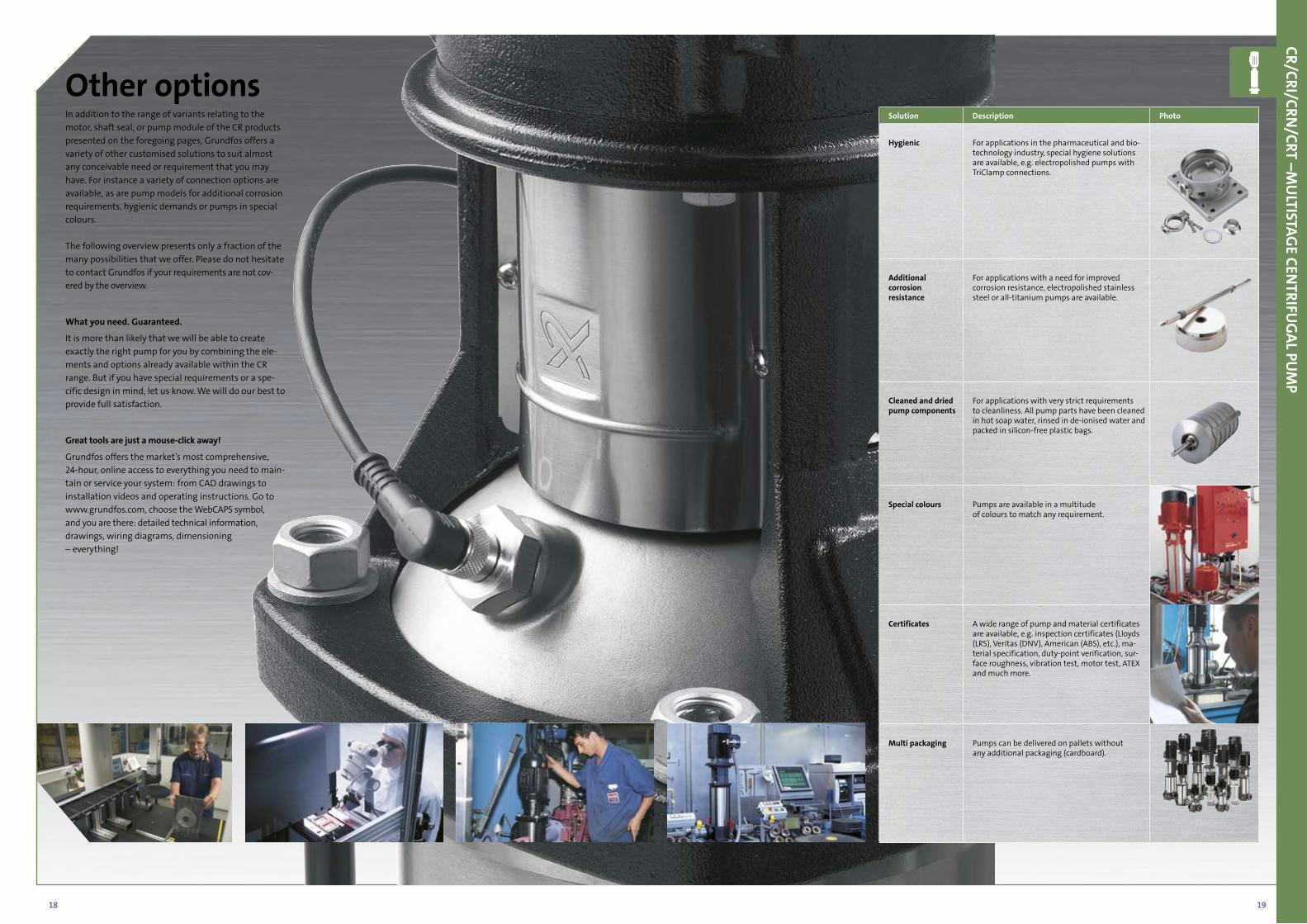
In addition to the range of variants relating to the motor, shaft seal, or pump module of the CR products presented on the foregoing pages, Grundfos offers a variety of other customised solutions to suit almost any conceivable need or requirement that you may have. For instance a variety of connection options are available, as are pump models for additional corrosion requirements, hygienic demands or pumps in special colours.
The following overview presents only a fraction of the many possibilities that we offer. Please do not hesitate to contact Grundfos if your requirements are not cov-ered by the overview.
What you need. Guaranteed.
It is more than likely that we will be able to create exactly the right pump for you by combining the ele-ments and options already available within the CR range. But if you have special requirements or a spe-cific design in mind, let us know. We will do our best to provide full satisfaction.
Great tools are just a mouse-click away!
Grundfos offers the market’s most comprehensive, 24-hour, online access to everything you need to main-tain or service your system: from CAD drawings to installation videos and operating instructions. Go to www.grundfos.com, choose the WebCAPS symbol, and you are there: detailed technical information, drawings, wiring diagrams, dimensioning – everything!
Other options
CR/CRI/CRN/CRT –M
ULTISTAG
E CENTRIFU
GAL PU
MP
Solution Description Photo
Hygienic For applications in the pharmaceutical and bio-technology industry, special hygiene solutions are available, e.g. electropolished pumps with TriClamp connections.
Additional corrosion resistance
For applications with a need for improved corrosion resistance, electropolished stainless steel or all-titanium pumps are available.
Cleaned and dried pump components
For applications with very strict requirements to cleanliness. All pump parts have been cleaned in hot soap water, rinsed in de-ionised water and packed in silicon-free plastic bags.
Special colours Pumps are available in a multitude of colours to match any requirement.
Certificates A wide range of pump and material certificates are available, e.g. inspection certificates (Lloyds (LRS), Veritas (DNV), American (ABS), etc.), ma-terial specification, duty-point verification, sur-face roughness, vibration test, motor test, ATEX and much more.
Multi packaging Pumps can be delivered on pallets without any additional packaging (cardboard).
20 21
10.8 11 1.5 2 3 4 5 6 8 1010 15 20 30 40 50 60 80 100100 150 200Q[ m³ /h]
20
30
40
60
80
100
200
300
400
H[m ]
60 Hz
CR150
CR120
CR1s CR10
CR15
CR20
CR1 CR64
CR45
CR32CR5
CR3
CRI1CR N1
CR I3CR N3
CRI5CRN5
CRN32 CRN64
CRN90CRN45CR I10CRN10
CRI15CRN15
CRI20CRN20
CR I1 sCR N1 s
CRN 120
CRN150
10. 8 11 1.5 2 3 4 5 6 8 1010 15 20 30 40 50 60 80 100100 150 200Q[ m³ /h]
20
30
40
60
80
100
200
300
400
H[m ]
50 Hz
CR150
CR120
CR1
CR3
CR5CRI1CRN1
CRI3CRN3
CRI5CRN5
CRN32
CRN64
CRN90CRN45
CR32
CR45
CR64
CR90
CR10CRI10CRN10
CR15CRI15CRN15
CR20CRI20CRN20
CR1sCRI1 sCRN1s
CRN120
CRN150
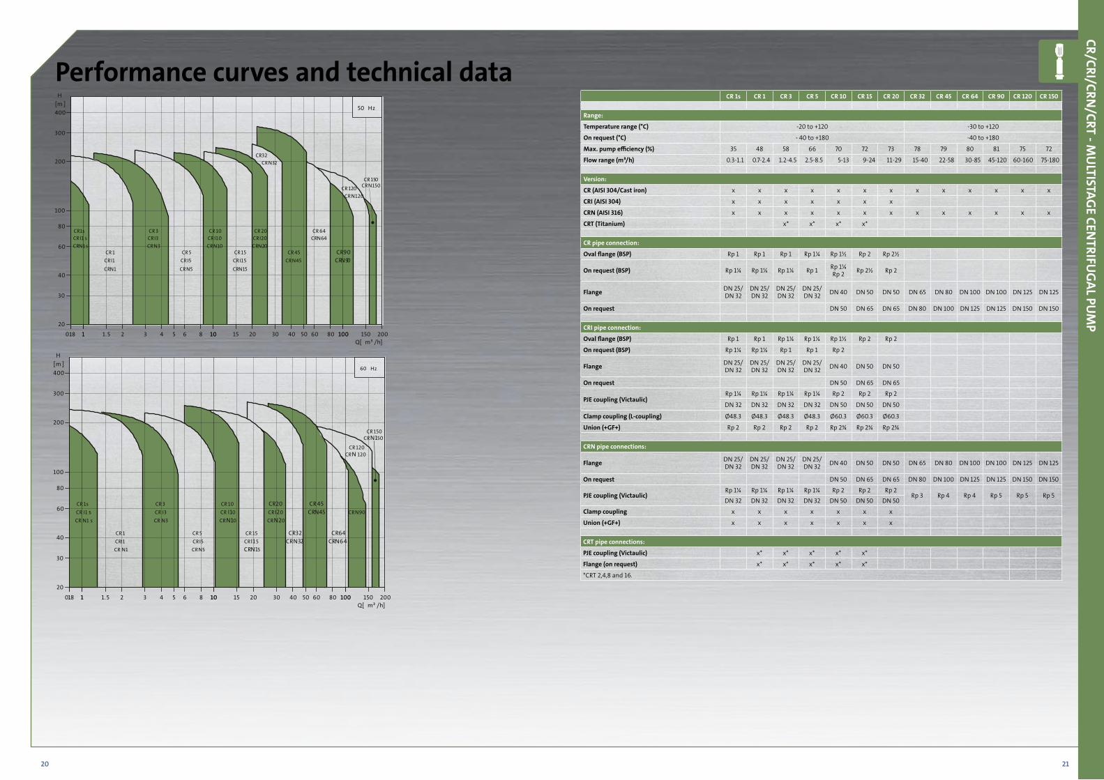
Performance curves and technical data
CR/CRI/CRN/CRT - M
ULTISTAG
E CENTRIFU
GAL PU
MP
CR 1s CR 1 CR 3 CR 5 CR 10 CR 15 CR 20 CR 32 CR 45 CR 64 CR 90 CR 120 CR 150
Range:
Temperature range (°C) -20 to +120 -30 to +120
On request (°C) - 40 to +180 -40 to +180
Max. pump efficiency (%) 35 48 58 66 70 72 73 78 79 80 81 75 72
Flow range (m³/h) 0.3-1.1 0.7-2.4 1.2-4.5 2.5-8.5 5-13 9-24 11-29 15-40 22-58 30-85 45-120 60-160 75-180
Version:
CR (AISI 304/Cast iron) x x x x x x x x x x x x x
CRI (AISI 304) x x x x x x x
CRN (AISI 316) x x x x x x x x x x x x x
CRT (Titanium) x* x* x* x*
CR pipe connection:
Oval flange (BSP) Rp 1 Rp 1 Rp 1 Rp 1¼ Rp 1½ Rp 2 Rp 2½
On request (BSP) Rp 1¼ Rp 1¼ Rp 1¼ Rp 1 Rp 1¼Rp 2 Rp 2½ Rp 2
Flange DN 25/DN 32
DN 25/DN 32
DN 25/DN 32
DN 25/DN 32 DN 40 DN 50 DN 50 DN 65 DN 80 DN 100 DN 100 DN 125 DN 125
On request DN 50 DN 65 DN 65 DN 80 DN 100 DN 125 DN 125 DN 150 DN 150
CRI pipe connection:
Oval flange (BSP) Rp 1 Rp 1 Rp 1¼ Rp 1¼ Rp 1½ Rp 2 Rp 2
On request (BSP) Rp 1¼ Rp 1¼ Rp 1 Rp 1 Rp 2
Flange DN 25/DN 32
DN 25/DN 32
DN 25/DN 32
DN 25/DN 32 DN 40 DN 50 DN 50
On request DN 50 DN 65 DN 65
PJE coupling (Victaulic)Rp 1¼ Rp 1¼ Rp 1¼ Rp 1¼ Rp 2 Rp 2 Rp 2
DN 32 DN 32 DN 32 DN 32 DN 50 DN 50 DN 50
Clamp coupling (L-coupling) Ø48.3 Ø48.3 Ø48.3 Ø48.3 Ø60.3 Ø60.3 Ø60.3
Union (+GF+) Rp 2 Rp 2 Rp 2 Rp 2 Rp 2¾ Rp 2¾ Rp 2¾
CRN pipe connections:
Flange DN 25/DN 32
DN 25/DN 32
DN 25/DN 32
DN 25/DN 32 DN 40 DN 50 DN 50 DN 65 DN 80 DN 100 DN 100 DN 125 DN 125
On request DN 50 DN 65 DN 65 DN 80 DN 100 DN 125 DN 125 DN 150 DN 150
PJE coupling (Victaulic)Rp 1¼ Rp 1¼ Rp 1¼ Rp 1¼ Rp 2 Rp 2 Rp 2
Rp 3 Rp 4 Rp 4 Rp 5 Rp 5 Rp 5DN 32 DN 32 DN 32 DN 32 DN 50 DN 50 DN 50
Clamp coupling x x x x x x x
Union (+GF+) x x x x x x x
CRT pipe connections:
PJE coupling (Victaulic) x* x* x* x* x*
Flange (on request) x* x* x* x* x*
*CRT 2,4,8 and 16.
22 23
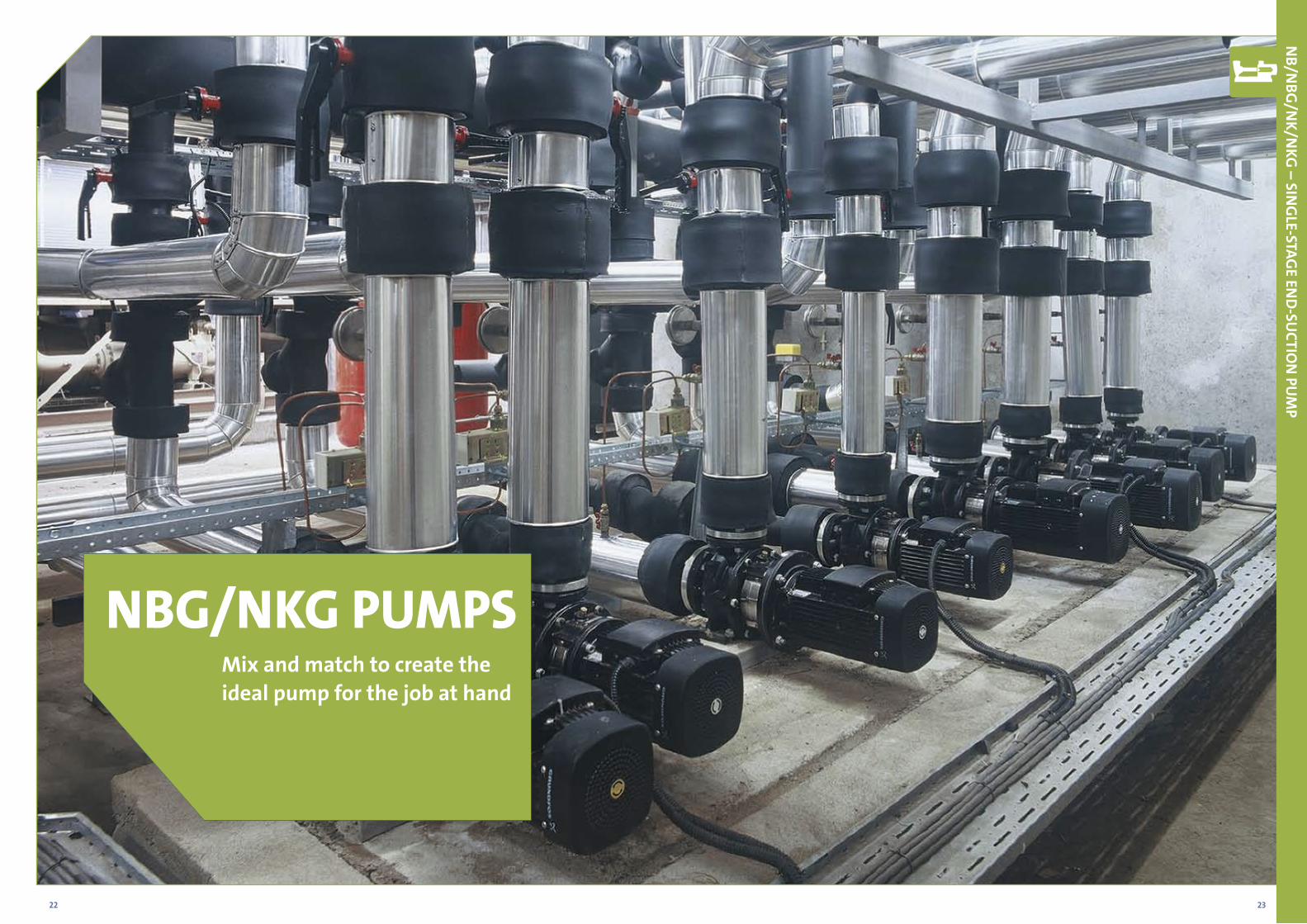
NBG/NKG PUMPSMix and match to create theideal pump for the job at hand
NB/N
BG/N
K/NKG
– SING
LE-STAGE EN
D-SU
CTION
PUM
P
24 25
Solution Description Photo
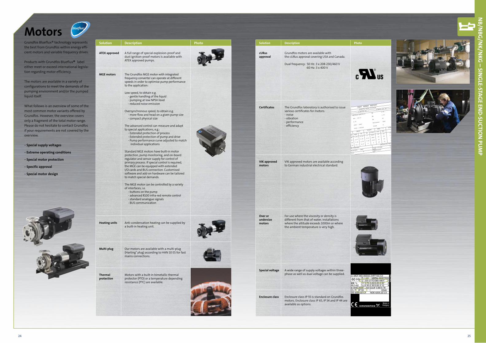
ATEX approved A full range of special explosion-proof and dust ignition-proof motors is available with ATEX approved pumps.
MGE motors The Grundfos MGE motor with integrated frequency converter can operate at different speeds in order to optimise pump performance to the application:
Low speed, to obtain e.g.- gentle handling of the liquid- pumping at low NPSH level- reduced noise emission
Oversynchronous speed, to obtain e.g.- more flow and head on a given pump size- compact physical size
The advanced control can measure and adapt to special applications, e.g.:
- Extended protection of process- Extended protection of pump and drive- Pump performance curve adjusted to match
individual applications
Standard MGE motors have built-in motor protection, pump monitoring, and on-board regulator and sensor supply for control of primary process. If special control is required, the MGE can be equipped with extended I/O cards and BUS connection. Customised software and add-on hardware can be tailored to match special demands.
The MGE motor can be controlled by a variety of interfaces, i.e.
- buttons on the pump- advanced R100 infra-red remote control- standard analogue signals- BUS communication
Heating units Anti-condensation heating can be supplied by a built-in heating unit.
Multi-plug Our motors are available with a multi-plug (Harting® plug) according to HAN 10 ES for fast mains connections.
Thermal protection
Motors with a built-in bimetallic thermal protector (PTO) or a temperature depending resistance (PTC) are available.
Solution Description Photo
cURus approval
Grundfos motors are available with the cURus approval covering USA and Canada.
Dual frequency: 50 Hz: 3 x 208-230/460 V 60 Hz: 3 x 400 V
Certificates The Grundfos laboratory is authorised to issue various certificates for motors:- noise- vibration- performance- efficiency
VIK approved motors
VIK approved motors are available according to German industrial electrical standard.
Over or undersize motors
For use where the viscosity or density is different from that of water, installations where the altitude exceeds 1000m or where the ambient temperature is very high.
Special voltage A wide range of supply voltages within three-phase as well as dual voltage can be supplied.
Enclosure class Enclosure class IP 55 is standard on Grundfos motors. Enclosure class IP 65, IP 54 and IP 44 are available as options.
NB/N
BG/N
K/NKG
– SING
LE-STAGE EN
D-SU
CTION
PUM
P
Grundfos Blueflux® technology represents the best from Grundfos within energy effi-cient motors and variable frequency drives.
Products with Grundfos Blueflux® label either meet or exceed international legisla-tion regarding motor efficiency.
The motors are available in a variety of configurations to meet the demands of the pumping environment and/or the pumped liquid itself.
What follows is an overview of some of the most common motor variants offered by Grundfos. However, the overview covers only a fragment of the total motor range. Please do not hesitate to contact Grundfos if your requirements are not covered by the overview.
• Special supply voltages
• Extreme operating conditions
• Special motor protection
• Specific approval
• Special motor design
Motors
60 Hz3~MOT MG 90SA2-24FF165-C2
Eff. %80.5-82n 3440-3500 min-1
CL F IP 55 0346DE 6305.2Z.C4 NDE 6205.2Z.C3
P 1.50 kW2
U 220-277D/380-480Y VI 5.70-5.00/3.30-2.90 AI 6.30-5.35/3.65-3.10 A
cos 0.89-0.78
1/1
max
8580
7906
No 85807906
26 27
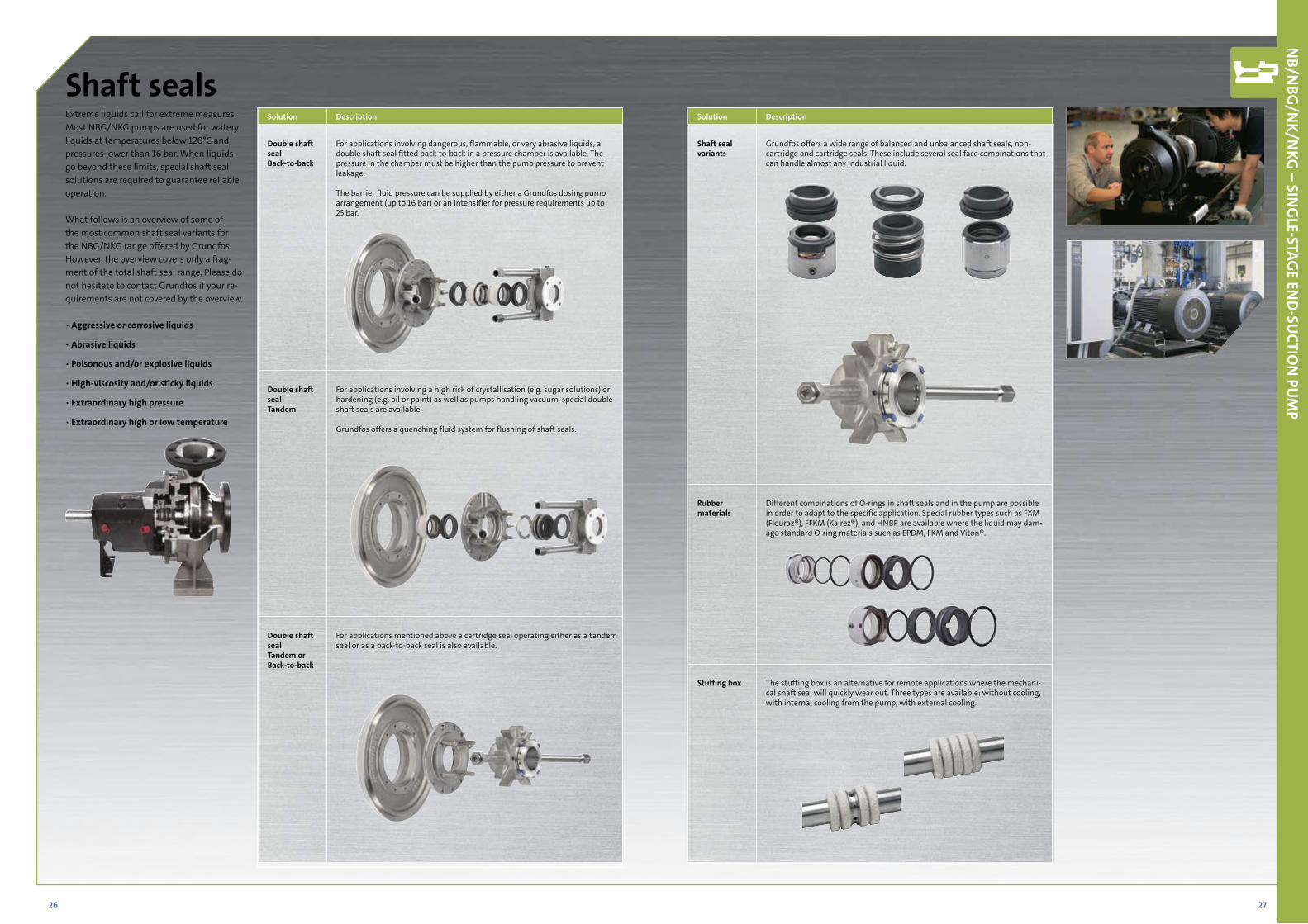
Extreme liquids call for extreme measures. Most NBG/NKG pumps are used for watery liquids at temperatures below 120°C and pressures lower than 16 bar. When liquids go beyond these limits, special shaft seal solutions are required to guarantee reliable operation.
What follows is an overview of some of the most common shaft seal variants for the NBG/NKG range offered by Grundfos. However, the overview covers only a frag-ment of the total shaft seal range. Please do not hesitate to contact Grundfos if your re-quirements are not covered by the overview.
• Aggressive or corrosive liquids
• Abrasive liquids
• Poisonous and/or explosive liquids
• High-viscosity and/or sticky liquids
• Extraordinary high pressure
• Extraordinary high or low temperature
Shaft seals
NB/N
BG/N
K/NKG
– SING
LE-STAGE EN
D-SU
CTION
PUM
P
Solution Description
Double shaft sealBack-to-back
For applications involving dangerous, flammable, or very abrasive liquids, a double shaft seal fitted back-to-back in a pressure chamber is available. The pressure in the chamber must be higher than the pump pressure to prevent leakage.
The barrier fluid pressure can be supplied by either a Grundfos dosing pump arrangement (up to 16 bar) or an intensifier for pressure requirements up to 25 bar.
Double shaft seal Tandem
For applications involving a high risk of crystallisation (e.g. sugar solutions) or hardening (e.g. oil or paint) as well as pumps handling vacuum, special double shaft seals are available.
Grundfos offers a quenching fluid system for flushing of shaft seals.
Double shaft sealTandem or Back-to-back
For applications mentioned above a cartridge seal operating either as a tandem seal or as a back-to-back seal is also available.
Solution Description
Shaft seal variants
Grundfos offers a wide range of balanced and unbalanced shaft seals, non-cartridge and cartridge seals. These include several seal face combinations that can handle almost any industrial liquid.
Rubber materials
Different combinations of O-rings in shaft seals and in the pump are possible in order to adapt to the specific application. Special rubber types such as FXM (Flouraz®), FFKM (Kalrez®), and HNBR are available where the liquid may dam-age standard O-ring materials such as EPDM, FKM and Viton®.
Stuffing box The stuffing box is an alternative for remote applications where the mechani-cal shaft seal will quickly wear out. Three types are available: without cooling, with internal cooling from the pump, with external cooling.
28 29
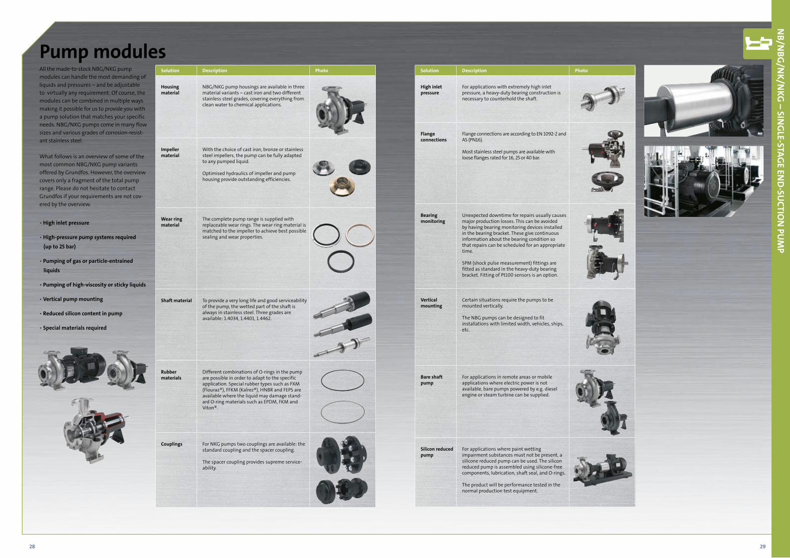
All the made-to-stock NBG/NKG pump modules can handle the most demanding of liquids and pressures – and be adjustable to virtually any requirement. Of course, the modules can be combined in multiple ways making it possible for us to provide you with a pump solution that matches your specific needs. NBG/NKG pumps come in many flow sizes and various grades of corrosion-resist-ant stainless steel.
What follows is an overview of some of the most common NBG/NKG pump variants offered by Grundfos. However, the overview covers only a fragment of the total pump range. Please do not hesitate to contact Grundfos if your requirements are not cov-ered by the overview.
• High inlet pressure
• High-pressure pump systems required
(up to 25 bar)
• Pumping of gas or particle-entrained
liquids
• Pumping of high-viscosity or sticky liquids
• Vertical pump mounting
• Reduced silicon content in pump
• Special materials required
Pump modules
NB/N
BG/N
K/NKG
– SING
LE-STAGE EN
D-SU
CTION
PUM
P
Solution Description Photo
Housing material
NBG/NKG pump housings are available in three material variants – cast iron and two different stainless steel grades, covering everything from clean water to chemical applications.
Impeller material
With the choice of cast iron, bronze or stainlesssteel impellers, the pump can be fully adaptedto any pumped liquid.
Optimised hydraulics of impeller and pumphousing provide outstanding efficiencies.
Wear ring material
The complete pump range is supplied with replaceable wear rings. The wear ring material is matched to the impeller to achieve best possible sealing and wear properties.
Shaft material To provide a very long life and good serviceability of the pump, the wetted part of the shaft is always in stainless steel. Three grades are available: 1.4034, 1.4401, 1.4462.
Rubber materials
Different combinations of O-rings in the pump are possible in order to adapt to the specific application. Special rubber types such as FXM (Flouraz®), FFKM (Kalrez®), HNBR and FEPS are available where the liquid may damage stand-ard O-ring materials such as EPDM, FKM and Viton®.
Couplings For NKG pumps two couplings are available: the standard coupling and the spacer coupling.
The spacer coupling provides supreme service-ability.
Solution Description Photo
High inlet pressure
For applications with extremely high inlet pressure, a heavy-duty bearing construction is necessary to counterhold the shaft.
Flange connections
Flange connections are according to EN 1092-2 and AS (PN16).
Most stainless steel pumps are available with loose flanges rated for 16, 25 or 40 bar.
Bearing monitoring
Unexpected downtime for repairs usually causes major production losses. This can be avoided by having bearing monitoring devices installed in the bearing bracket. These give continuous information about the bearing condition so that repairs can be scheduled for an appropriate time.
SPM (shock pulse measurement) fittings are fitted as standard in the heavy-duty bearing bracket. Fitting of Pt100 sensors is an option.
Vertical mounting
Certain situations require the pumps to be mounted vertically.
The NBG pumps can be designed to fit installations with limited width, vehicles, ships, etc.
Bare shaft pump
For applications in remote areas or mobile applications where electric power is not available, bare pumps powered by e.g. diesel engine or steam turbine can be supplied.
Silicon reduced pump
For applications where paint wetting impairment substances must not be present, a silicone reduced pump can be used. The silicon reduced pump is assembled using silicone-free components, lubrication, shaft seal, and O-rings.
The product will be performance tested in the normal production test equipment.
30 31
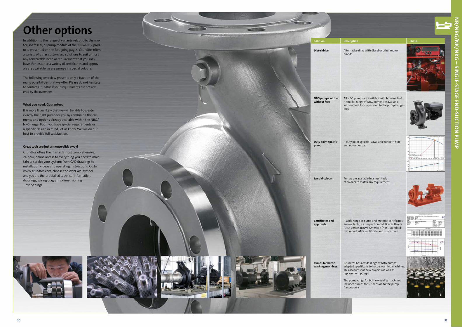
In addition to the range of variants relating to the mo-tor, shaft seal, or pump module of the NBG/NKG prod-ucts presented on the foregoing pages, Grundfos offers a variety of other customised solutions to suit almost any conceivable need or requirement that you may have. For instance a variety of certificates and approv-als are available, as are pumps in special colours.
The following overview presents only a fraction of the many possibilities that we offer. Please do not hesitate to contact Grundfos if your requirements are not cov-ered by the overview.
What you need. Guaranteed
It is more than likely that we will be able to create exactly the right pump for you by combining the ele-ments and options already available within the NBG/NKG range. But if you have special requirements or a specific design in mind, let us know. We will do our best to provide full satisfaction.
Great tools are just a mouse-click away!
Grundfos offers the market’s most comprehensive, 24-hour, online access to everything you need to main-tain or service your system: from CAD drawings to installation videos and operating instructions. Go to www.grundfos.com, choose the WebCAPS symbol, and you are there: detailed technical information, drawings, wiring diagrams, dimensioning – everything!
Other options
NB/N
BG/N
K/NKG
– SING
LE-STAGE EN
D-SU
CTION
PUM
P
Solution Description Photo
Diesel drive Alternative drive with diesel or other motor brands.
NBG pumps with or without feet
All NBG pumps are available with housing feet.A smaller range of NBG pumps are available without feet for suspension to the pump flanges only.
Duty point specific pump
A duty point specific is available for both bloc and norm pumps.
Special colours Pumps are available in a multitude of colours to match any requirement.
Certificates and approvals
A wide range of pump and material certificates are available, e.g. inspection certificates Lloyds (LRS), Veritas (DNV), American (ABS), standard test report, ATEX certificate and much more.
Pumps for bottle washing machines
Grundfos has a wide range of NBG pumps adapted specifically to bottle washing machines. This accounts for new projects as well as replacement pumps.
The pump range for bottle washing machines includes pumps for suspension to the pump flanges only.
32 33
4 6 1010 20 40 60 100100 200 400 600 10001000Q [m³/h]
8
10
15
20
30
40
5060
80
100120
150
200[m]H
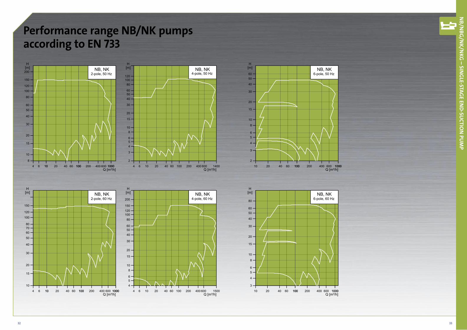
NB, NK2-pole, 50 Hz
4 6 10 20 40 60 100 200 400 600 1400Q [m³/h]
2
3
456
810
15
20
30
405060
80100120
[m]H
NB, NK4-pole, 50 Hz
10 20 40 60 100100 200 400 600 10001000Q [m³/h]
2
3
4
56
8
10
15
20
30
40
5060
[m]H
NB, NK6-pole, 50 Hz
4 6 1010 20 40 60 100100 200 400 600 10001000Q [m³/h]
10
15
20
30
40
50
607080
100
120
150
[m]H
NB, NK2-pole, 60 Hz
4 6 10 20 40 60 100 200 400 600 1500Q [m³/h]
456
810
15
20
30
405060
80100120150
200
[m]H
NB, NK4-pole, 60 Hz
10 20 40 60 100100 200 400 600 10001000Q [m³/h]
3
4
56
8
10
15
20
30
40
5060
80
[m]H
NB, NK6-pole, 60 Hz
Performance range NB/NK pumps according to EN 733
NB/N
BG/N
K/NKG
– SING
LE-STAGE EN
D-SU
CTION
PUM
P
34 35
4 6 10 20 40 60 100 200 400 600 1400Q [m³/h]
8
1012
15
20
30
40
50607080
100120
150
200[m]H
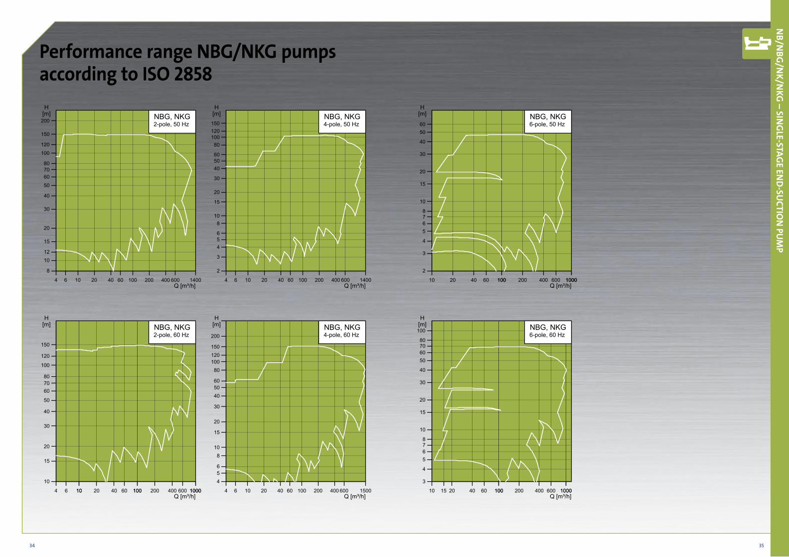
NBG, NKG2-pole, 50 Hz
4 6 10 20 40 60 100 200 400 600 1400Q [m³/h]
2
3
456
810
15
20
30
405060
80100120150
[m]H
NBG, NKG4-pole, 50 Hz
10 20 40 60 100100 200 400 600 10001000Q [m³/h]
2
3
4
5678
10
15
20
30
40
5060
[m]H
NBG, NKG6-pole, 50 Hz
4 6 1010 20 40 60 100100 200 400 600 10001000Q [m³/h]
10
15
20
30
40
50
607080
100
120
150
[m]H
NBG, NKG2-pole, 60 Hz
4 6 10 20 40 60 100 200 400 600 1500Q [m³/h]
456
810
15
20
30
405060
80100120150
200
[m]H
NBG, NKG4-pole, 60 Hz
10 15 20 40 60 100100 200 400 600 10001000Q [m³/h]
3
4
5678
10
15
20
30
40
50607080
100[m]H
NBG, NKG6-pole, 60 Hz
Performance range NBG/NKG pumps according to ISO 2858
NB/N
BG/N
K/NKG
– SING
LE-STAGE EN
D-SU
CTION
PUM
P
36 37
Pump size
NBG NKG Cast iron pump Stainless steel pumpCastiron
pump
Stainless steel
pump
Castiron
pump
Stainless steel
pump
Flange rating
Flange standard
Flange rating
Flange standard
EN-G
JL-2
50
1.44
08
1.45
17
Sing
le m
ech.
seal
Dou
ble
mec
h. se
al
Cart
ridge
seal
- si
ngle
/dou
ble
Pum
p w
ithou
t fee
t
Pum
p w
ith su
ppor
t blo
cks
Base
fram
e
EN-G
JL-2
50
1.44
08
1.45
17
Sing
le m
ech.
seal
Dou
ble
mec
h. se
al
Cart
ridge
seal
- si
ngle
/dou
ble
Stuf
fing
box
Hea
vy d
uty
bear
ing
brac
ket
Bear
ing
mon
itorin
g
PN 1
0
PN 1
6
DIN
(cod
e F)
ANSI
(cod
e G
)
JIS (c
ode
J)
PN 1
6
PN 2
5
DIN
(cod
e F)
DIN
(cod
e F)
ANSI
(cod
e G
)
JIS (c
ode
J)
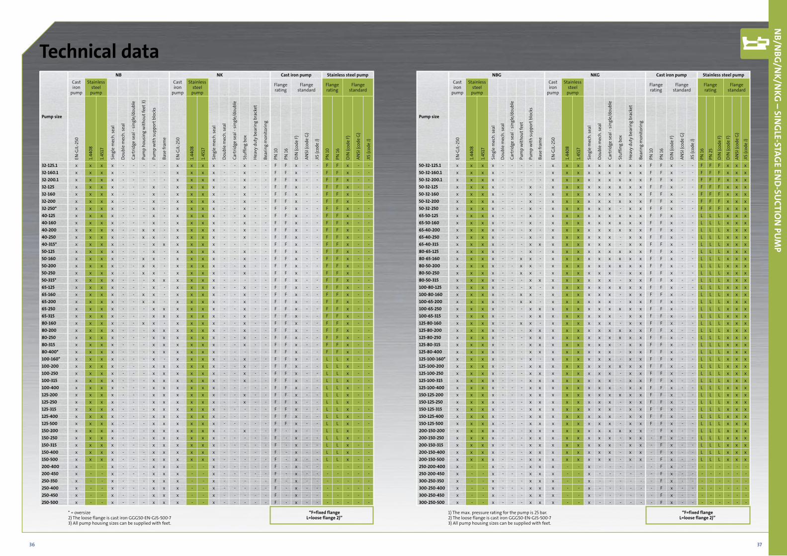
50-32-125.1 x x x x - - - - - x x x x x x x x x F F x - - F F F x x x50-32-160.1 x x x x - - - - - x x x x x x x x x F F x - - F F F x x x50-32-200.1 x x x x - - - - - x x x x x x x x x F F x - - F F F x x x50-32-125 x x x x - - - x - x x x x x x x x x F F x - - F F F x x x50-32-160 x x x x - - - x - x x x x x x x x x F F x - - F F F x x x50-32-200 x x x x - - - x - x x x x x x x x x F F x - - F F F x x x50-32-250 x x x x - - - x - x x x x x x - x x F F x - - F F F x x x65-50-125 x x x x - - - x - x x x x x x x x x F F x - - L L L x x x65-50-160 x x x x - - - x - x x x x x x x x x F F x - - L L L x x x65-40-200 x x x x - - - x - x x x x x x x x x F F x - - L L L x x x65-40-250 x x x x - - - x - x x x x x x - x x F F x - - L L L x x x65-40-315 x x x x - - - x x x x x x x x - x x F F x - - L L L x x x80-65-125 x x x x - - - x - x x x x x x x x x F F x - - L L L x x x80-65-160 x x x x - - x x - x x x x x x x x x F F x - - L L L x x x80-50-200 x x x x - - x x - x x x x x x x x x F F x - - L L L x x x80-50-250 x x x x - - x x - x x x x x x - x x F F x - - L L L x x x80-50-315 x x x x - - - x x x x x x x x - x x F F x - - L L L x x x100-80-125 x x x x - - - x - x x x x x x x x x F F x - - L L L x x x100-80-160 x x x x - - x x - x x x x x x - x x F F x - - L L L x x x100-65-200 x x x x - - x x - x x x x x x - x x F F x - - L L L x x x100-65-250 x x x x - - - x x x x x x x x x x x F F x - - L L L x x x100-65-315 x x x x - - - x x x x x x x x - x x F F x - - L L L x x x125-80-160 x x x x - - x x - x x x x x x - x x F F x - - L L L x x x125-80-200 x x x x - - - x x x x x x x x x x x F F x - - L L L x x x125-80-250 x x x x - - - x x x x x x x x x x x F F x - - L L L x x x125-80-315 x x x x - - - x x x x x x x x - x x F F x - - L L L x x x125-80-400 x x x x - - - x x x x x x x x - x x F F x - - L L L x x x125-100-160* x x x x - - - x - x x x x x x - x x F F x - - L L L x x x125-100-200 x x x x - - - x x x x x x x x x x x F F x - - L L L x x x125-100-250 x x x x - - - x x x x x x x x - x x F F x - - L L L x x x125-100-315 x x x x - - - x x x x x x x x - x x F F x - - L L L x x x125-100-400 x x x x - - - x x x x x x x x - x x F F x - - L L L x x x150-125-200 x x x x - - - x x x x x x x x x x x F F x - - L L L x x x150-125-250 x x x x - - - x x x x x x x x - x x F F x - - L L L x x x150-125-315 x x x x - - - x x x x x x x x - x x F F x - - L L L x x x150-125-400 x x x x - - - x x x x x x x x - x x F F x - - L L L x x x150-125-500 x x x x - - - x x x x x x x x - x x F F x - - L L L x x x200-150-200 x x x x - - - x x x x x x x x x x x - F x - - L L L x x x200-150-250 x x x x - - - x x x x x x x x - x x - F x - - L L L x x x200-150-315 x x x x - - - x x x x x x x x - x x - F x - - L L L x x x200-150-400 x x x x - - - x x x x x x x x - x x - F x - - L L L x x x200-150-500 x x x x - - - x x x x x x x x - x x - F x - - L L L x x x250-200-400 x - - x - - - x x x - - x - - - - - - F x - - - - - - - - 250-200-450 x - - x - - - x x x - - x - - - - - - F x - - - - - - - - 300-250-350 x - - x - - - x x x - - x - - - - - - F x - - - - - - - - 300-250-400 x - - x - - - x x x - - x - - - - - - F x - - - - - - - - 300-250-450 x - - x - - - x x x - - x - - - - - - F x - - - - - - - - 300-250-500 x - - x - - - x x x - - x - - - - - - F x - - - - - - - -
1) The max. pressure rating for the pump is 25 bar. 2) The loose flange is cast iron GGG50-EN-GJS-500-7 3) All pump housing sizes can be supplied with feet.
“F=fixed flange L=loose flange 2)”
NB/N
BG/N
K/NKG
– SING
LE-STAGE EN
D-SU
CTION
PUM
P
Technical data
Pump size
NB NK Cast iron pump Stainless steel pumpCastiron
pump
Stainless steel
pump
Castiron
pump
Stainless steel
pump
Flange rating
Flange standard
Flange rating
Flange standard
EN-G
JL-2
50
1.44
08
1.45
17
Sing
le m
ech.
seal
Dou
ble
mec
h. se
al
Cart
ridge
seal
- si
ngle
/dou
ble
Pum
p ho
usin
g w
ithou
t fee
t 3)
Pum
p w
ith su
ppor
t blo
cks
Base
fram
e
EN-G
JL-2
50
1.44
08
1.45
17
Sing
le m
ech.
seal
Dou
ble
mec
h. se
al
Cart
ridge
seal
- si
ngle
/dou
ble
Stuf
fing
box
Hea
vy d
uty
bear
ing
brac
ket
Bear
ing
mon
itorin
g
PN 1
0
PN 1
6
DIN
(cod
e F)
ANSI
(cod
e G
)
JIS (c
ode
J)
PN 1
0
PN 1
6
DIN
(cod
e F)
ANSI
(cod
e G
)
JIS (c
ode
J)
32-125.1 x x x x - - - - - x x x x - - x - - F F x - - F F x - - 32-160.1 x x x x - - - - - x x x x - - x - - F F x - - F F x - - 32-200.1 x x x x - - - - - x x x x - - x - - F F x - - F F x - - 32-125 x x x x - - - x - x x x x - - x - - F F x - - F F x - - 32-160 x x x x - - - x - x x x x - - x - - F F x - - F F x - - 32-200 x x x x - - - x - x x x x - - x - - F F x - - F F x - - 32-250* x x x x - - - x - x x x x - - x - - F F x - - F F x - - 40-125 x x x x - - - x - x x x x - - x - - F F x - - F F x - - 40-160 x x x x - - - x - x x x x - - x - - F F x - - F F x - - 40-200 x x x x - - x x - x x x x - - x - - F F x - - F F x - - 40-250 x x x x - - x x - x x x x - - x - - F F x - - F F x - - 40-315* x x x x - - - x x x x x x - - - - - F F x - - F F x - - 50-125 x x x x - - - x - x x x x - - x - - F F x - - F F x - - 50-160 x x x x - - x x - x x x x - - x - - F F x - - F F x - - 50-200 x x x x - - x x - x x x x - - x - - F F x - - F F x - - 50-250 x x x x - - x x - x x x x - - x - - F F x - - F F x - - 50-315* x x x x - - - x x x x x x - - - - - F F x - - F F x - - 65-125 x x x x - - - x - x x x x - - x - - F F x - - F F x - - 65-160 x x x x - - x x - x x x x - - x - - F F x - - F F x - - 65-200 x x x x - - x x - x x x x - - x - - F F x - - F F x - - 65-250 x x x x - - - x x x x x x - - x - - F F x - - F F x - - 65-315 x x x x - - - x x x x x x - - x - - F F x - - F F x - - 80-160 x x x x - - x x - x x x x - - x - - F F x - - F F x - - 80-200 x x x x - - - x x x x x x - - x - - F F x - - F F x - - 80-250 x x x x - - - x x x x x x - - x - - F F x - - F F x - - 80-315 x x x x - - - x x x x x x - - x - - F F x - - F F x - - 80-400* x x x x - - - x x x x x x - - - - - F F x - - F F x - - 100-160* x x x x - - - x - x x x x - - x - - F F x - - L L x - - 100-200 x x x x - - - x x x x x x - - x - - F F x - - L L x - - 100-250 x x x x - - - x x x x x x - - x - - F F x - - L L x - - 100-315 x x x x - - - x x x x x x - - x - - F F x - - L L x - - 100-400 x x x x - - - x x x x x x - - - - - F F x - - L L x - - 125-200 x x x x - - - x x x x x x - - x - - F F x - - L L x - - 125-250 x x x x - - - x x x x x x - - x - - F F x - - L L x - - 125-315 x x x x - - - x x x x x x - - - - - F F x - - L L x - - 125-400 x x x x - - - x x x x x x - - - - - F F x - - L L x - - 125-500 x x x x - - - x x x x x x - - - - - F F x - - L L x - - 150-200 x x x x - - - x x x x x x - - x - - F - x - - L L x - - 150-250 x x x x - - - x x x x x x - - - - - F - x - - L L x - - 150-315 x x x x - - - x x x x x x - - - - - F - x - - L L x - - 150-400 x x x x - - - x x x x x x - - - - - F - x - - L L x - - 150-500 x x x x - - - x x x x x x - - - - - F - x - - L L x - - 200-400 x - - x - - - x x x - - x - - - - - F - x - - - - - - - 200-450 x - - x - - - x x x - - x - - - - - F - x - - - - - - - 250-350 x - - x - - - x x x - - x - - - - - F - x - - - - - - - 250-400 x - - x - - - x x x - - x - - - - - F - x - - - - - - - 250-450 x - - x - - - x x x - - x - - - - - F - x - - - - - - - 250-500 x - - x - - - x x x - - x - - - - - F - x - - - - - - -
* = oversize 2) The loose flange is cast iron GGG50-EN-GJS-500-7 3) All pump housing sizes can be supplied with feet.
“F=fixed flange L=loose flange 2)”
38 39
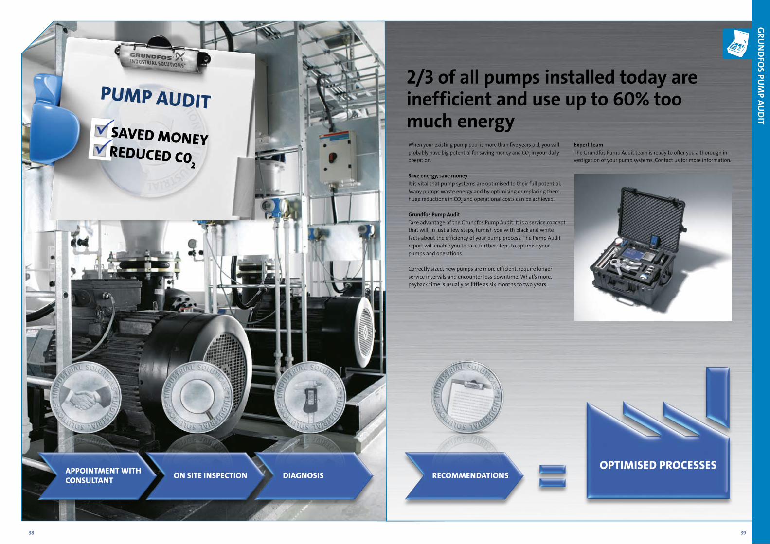
2/3 of all pumps installed today are inefficient and use up to 60% too much energy
GRU
ND
FOS PU
MP AU
DIT
When your existing pump pool is more than five years old, you will probably have big potential for saving money and CO2 in your daily operation.
Save energy, save moneyIt is vital that pump systems are optimised to their full potential. Many pumps waste energy and by optimising or replacing them, huge reductions in CO2 and operational costs can be achieved.
Grundfos Pump AuditTake advantage of the Grundfos Pump Audit. It is a service concept that will, in just a few steps, furnish you with black and white facts about the efficiency of your pump process. The Pump Audit report will enable you to take further steps to optimise your pumps and operations.
Correctly sized, new pumps are more efficient, require longer service intervals and encounter less downtime. What’s more, payback time is usually as little as six months to two years.
Expert teamThe Grundfos Pump Audit team is ready to offer you a thorough in-vestigation of your pump systems. Contact us for more information.
PUMP aUditSaved MoNeyRedUCed C0
2
aPPoiNtMeNt with CoNSUltaNt oN Site iNSPeCtioN diaGNoSiS ReCoMMeNdatioNS
oPtiMiSed PRoCeSSeS
Customisation made easyIn order to meet all customer requirements with complete
precision, Grundfos has developed a unique mix-and-match
approach to customised pumps. The elements of the CR and
NBG/NKG ranges can be combined any which way to create
the solution that is exactly right for you.
Grundfos: a pump for every purposeGrundfos offers much more. A complete range of pump
solutions means that all applications – industrial and
domestic – can benefit from the Grundfos touch.
• Heating
• Cooling
• Water Supply
• Wastewater
• Fire Fighting
• Dosing
• Industrial Processes
Being responsible is our foundation Thinking ahead makes it possible
Innovation is the essence
GRUNDFOS Management A/SPoul Due Jensens Vej 7DK-8850 BjerringbroTel: +45 87 50 14 00
www.grundfos.comThe name Grundfos, the Grundfos logo, and the payoff Be–Think–Innovate are registrated trademarks owned by Grundfos Management A/S or Grundfos A/S, Denmark. All rights reserved worldwide.
9791
5212
/Ind
ustr
y/09
11/9
857-
D&
I