Design criteria for a Total Knee prosthesis for the Indian population
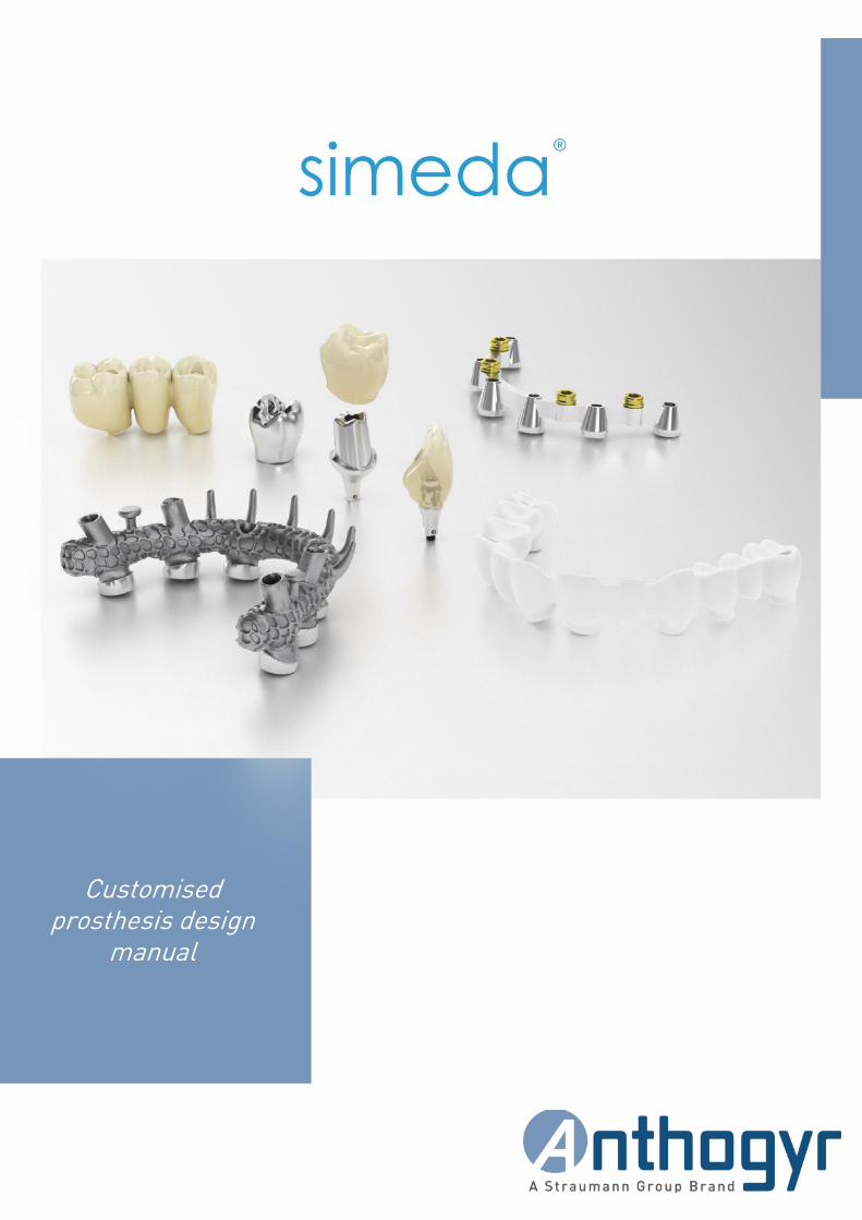
Customised prosthesis design
manual

2
TABLE OF CONTENT
Responsibility and warranty 4
1. Responsibility 4
2. Serenity® Guarantee 4
Anthogyr CAD/CAM restoration 5
1. Simeda® Restorations 5
2. Different types of prostheses 5
3. CAD/CAM materials available 7
4. Platforms available 8
WebOrder 10
1. Order via WebOrder 10
2. Preparation of the master model 10
3. Order by submitting a file 11
4. Order by submitting a model 12
5. Delivery times 15
Validation of your scanner 16
1. Explanations 16
2. Terms and conditions 16
3. Validity 16
Digitisation 17
Design of personalised Simeda® abutments 19
1. Indications and profiles available 19
2. Design limits 19
3. Specifications for customised abutments on Axiom® BL & TL titanium base 20
4. Specifications for AxIN® screw-retained teeth 21
3
CUSTOMISED PROSTHESI S DESIGN MANUAL
Design of Simeda® implant bridges 22
1. Indications and profiles available 22
2. Design limits 23
3. Specifications for customised prostheses with inLink® connection 24
4. Specifications for customised prostheses with Multi-Unit Angulated Access 25
Design of superstructures type Simeda® implant stilt 26
1. Indications and profiles available 26
2. Design limits 27
3. Specifications for customised Simeda® prostheses with inLink® connection 27
4. Specifications for customised prostheses with Angulated Access 27
Design of implant bars for Simeda® removable prostheses 28
1. Implant bars for clips 28
A. INDICATIONS AND PROFILES AVAILABLE 28
B. DESIGN LIMITS 29
C. SPECIFICATIONS FOR CUSTOMISED PROSTHESES ON AXIOM® TL PLATFORM 29
2. Implant bars for attachments 30
A. INDICATIONS AND PROFILES AVAILABLE 30
B. DESIGN LIMITS 32
C. SPECIFICATIONS FOR CUSTOMISED PROSTHESES ON AXIOM® TL PLATFORM 32
Design of tooth-supported prostheses 33
1. Tooth-supported restorations 33
2. Model preparation 33
3. Design limits 33

4
Responsibility and warranty
1. Responsibility Anthogyr is committed to respecting the morphology validated by the laboratory within the capabilities of machining equipment. The implant connections are controlled by a 3D machine for multiple-unit restorations and by mechanical measurements for single-unit restorations. The customised products manufactured are validated with the final
prosthetic check: check on the master model or on the analogue if required by the customer file.
Upon receiving a customised part manufactured by Anthogyr, the dental technician and the dentist approve the part
before use.
The implant connections of the Anthogyr customised prostheses need no modification.
→ If required by the clinical situation, modifications to zirconia prostheses should be done with a high-speed fine-grain diamond tool under abundant irrigation, and cobalt-chrome and titanium prostheses with a tungsten carbide tool, within the design limits defined in this manual. For cobalt-chrome frames designed to be coated with ceramic directly, use
mineral-based finishing burs, and avoid diamond and tungsten tools (risk of bubbles appearing).
→ ANY MODIFICATION CONSTITUTES A RISK OF MECHANICALLY WEAKENING THE PART. These components should be installed by clinicians trained in dental implantology only. Prosthetic parts must be
attached to avoid inhaling them or swallowing them during intraoral use.
In case of defects, Anthogyr has no other obligation than replacing the part. Under no circumstances will Anthogyr be
responsible for procedures performed by the prosthetist and the practitioner.
As provided for by law, Anthogyr guarantees the customer against any hidden defect due to defective materials, design
or production affecting the products delivered and rendering them unfit for use.
Guarantees do not apply in the event of misuse, negligence or poor maintenance on the part of the buyer, as in the case
of normal wear.
All brands and company names belong to their respective owners
2. Serenity® Guarantee
The customised prostheses manufactured by Anthogyr benefit from the Serenity® guarantee programme.
Anthogyr cannot be held liable for any clinical problems and accepts no liability for anything that is the responsibility of the dental technician and/or dentist. Approval of the customised dental prosthesis is the responsibility of the laboratory and of the dentist. If the order is made by master model, Anthogyr will send a design file and the product will be
machined only after receiving confirmation by the laboratory or the dentist in WebOrder.
In order to exercise their rights, the customer must return the Serenity® form, duly completed, and the defective part to
Anthogyr no more than 90 days after becoming aware of any flaws.
The replacement of defective components will not extend the conditions of the aforementioned guarantee.
For any additional information, please refer to the general warranty conditions of the Anthogyr Serenity® programme on
www.anthogyr.fr/services/anthogyr-serenity
The Serenity® programme applies to all the subsidiaries of the Anthogyr group. The other countries are covered by a 5-
year product guarantee.
5
CUSTOMISED PROSTHESI S DESIGN MANUAL
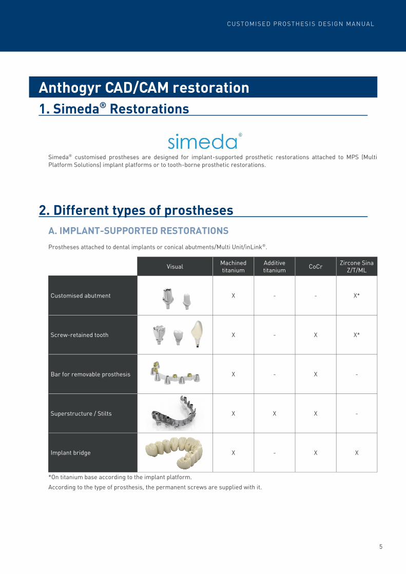
1. Simeda® Restorations
Simeda® customised prostheses are designed for implant-supported prosthetic restorations attached to MPS (Multi
Platform Solutions) implant platforms or to tooth-borne prosthetic restorations.
2. Different types of prostheses
A. IMPLANT-SUPPORTED RESTORATIONS
Prostheses attached to dental implants or conical abutments/Multi Unit/inLink®.
*On titanium base according to the implant platform.
According to the type of prosthesis, the permanent screws are supplied with it.
Anthogyr CAD/CAM restoration
Visual
Machined titanium
CoCr Zircone Sina
Z/T/ML Additive titanium
Customised abutment X - X* -
Screw-retained tooth X X X* -
Bar for removable prosthesis X X - -
Superstructure / Stilts X X - X
Implant bridge X X X -

6
B. TOOTH-SUPPORTED RESTORATIONS
Cemented prostheses on natural teeth or on implant abutments.
* Manufactured by Vita
** Manufactured by IVOCLAR VIVADENT
Visual Titanium CoCr Sina Z/T/ML
zirconia Vita
ENAMIC®*
Vita SUPRINITY®
PC*
IPS e.max®
CAD**
Bridge with 2 to 14 elements
X X X - - -
Coping
X X X - - -
Inlay / Onlay and veneer
- - X X X X
Crown
- - X X X X

7
CUSTOMISED PROSTHESI S DESIGN MANUAL
3. CAD/CAM materials available
GRADE V TITANIUM (ACCORDING TO ISO (5832-3)
→ Milled Ti: machined titanium → Additive titanium: additive titanium with rough or textured surface → Resistance to breakage >860 MPa → Young’s Modulus 110GPa → Vickers Hardness 350 HV → Thermal expansion coefficient 10.3 µm/mK → Volume mass 4.42 g/cm3 → Please refer to the information sheet “Technical specifications of Titanium”
TYPE V COBALT-CHROME (ACCORDING TO ISO 22674)
→ Resistance to breakage >900 MPa → Vickers Hardness 275 HV → Thermal expansion coefficient 14.2±0.3 µm/mK → Volume mass 8.3 g/cm3 → Please refer to the information sheet “Technical properties of Simeda® cobalt-chrome alloy”
SINA Z/T/ML ZIRCONIA (ACCORDING TO ISO 6872)
→ Sina Z: opaque zirconia, available in 16 shades → Sina T: translucent zirconia, available in 16 shades → Sina ML: multi-layer zirconia, available in 6 shades → Resistance to breakage >1150 MPa → Young’s Modulus 210GPa → Vickers Hardness 1250 HV → Thermal expansion coefficient 10 µm/mK → Please refer to the information sheet “Technical properties of Sina Z/T zirconia and Sina ML zirconia”
VITA ENAMIC®
→ Single-unit, crown type, inlay/onlay veneer restorations → Resistance to breakage >150-160 MPa
VITA SUPRINITY® PC
→ Single-unit, crown type, inlay/onlay veneer restorations → Resistance to breakage 420 MPa → Thermal expansion coefficient 12.3 µm/mK
IPS E.MAX CAD
→ Single-unit, crown type, inlay/onlay veneer restorations → Resistance to breakage 360 MPa → Thermal expansion coefficient 10.5 µm/mK

8
4. Platforms available
A. AXIOM® MULTI LEVEL® PLATFORMS
AXIOM® BL, BONE LEVEL
→ The Axiom® BL implants present a single-unit connection Ø2.7 mm. → They are used in combination with Multi Unit abutments or inLink® abutments for multiple-unit screw-retained
restorations.
.
COMPATIBILITY WITH AXIOM® BL PLATFORM
• Single-unit screw-retained indexed restoration : → single diameter Ø2.7 mm → Indexed conical connection
→ M1.6 threading
• Multiple-unit screw-retained restoration on
Multi-Unit abutments : → 2 platform diameters: Ø4.0/Ø4.8 → Non-indexed flat connection → M1.4 threading
• Multiple-unit screw-retained restoration on inLink® abutments : → 2 platform diameters: N: Ø4.0 / R: Ø4.8 → Non-indexed flat connection → M2.8 threading
Prosthesis
Axiom® BL implant
Customised abutment
Axiom® BL M1.6 screw
Multi Unit abutment
Axiom® BL implant
Prosthesis
Multi Unit M1.4 screw
Retaining ring
Lock (guide)
Axiom® BL implant
Prosthesis
InLink® abutment
Connections available
Indexed conical connection Non-indexed flat connection
(Multi Unit) Non-indexed flat connection
(inLink®)
Single-unit prosthesis X IMPOSSIBLE IMPOSSIBLE
Multiple-unit screw-retained prosthesis
IMPOSSIBLE X X
Implant bar IMPOSSIBLE X IMPOSSIBLE
9
CUSTOMISED PROSTHESI S DESIGN MANUAL
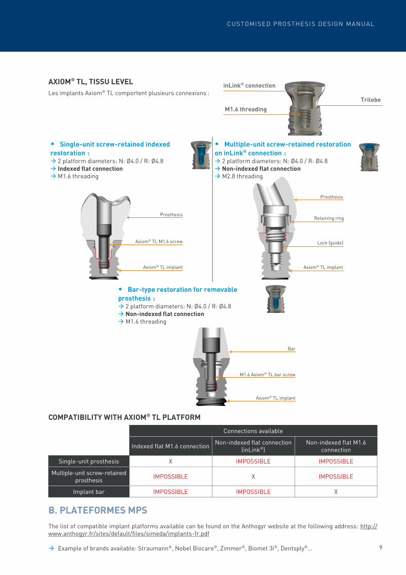
AXIOM® TL, TISSU LEVEL
Les implants Axiom® TL comportent plusieurs connexions :
COMPATIBILITY WITH AXIOM® TL PLATFORM
B. PLATEFORMES MPS
The list of compatible implant platforms available can be found on the Anthogyr website at the following address: http://www.anthogyr.fr/sites/default/files/simeda/implants-fr.pdf → Example of brands available: Straumann®, Nobel Biocare®, Zimmer®, Biomet 3i®, Dentsply®…
inLink® connection
M1.6 threading
• Single-unit screw-retained indexed
restoration : → 2 platform diameters: N: Ø4.0 / R: Ø4.8 → Indexed flat connection → M1.6 threading
• Multiple-unit screw-retained restoration
on inLink® connection : → 2 platform diameters: N: Ø4.0 / R: Ø4.8 → Non-indexed flat connection → M2.8 threading
• Bar-type restoration for removable
prosthesis : → 2 platform diameters: N: Ø4.0 / R: Ø4.8 → Non-indexed flat connection → M1.6 threading
Retaining ring
Lock (guide)
Axiom® TL implant
Prosthesis
Prosthesis
Axiom® TL implant
Axiom® TL M1.6 screw
Bar
Axiom® TL implant
M1.6 Axiom® TL bar screw
Trilobe
Connections available
Indexed flat M1.6 connection Non-indexed flat connection
(inLink®) Non-indexed flat M1.6
connection
Single-unit prosthesis X IMPOSSIBLE IMPOSSIBLE
Multiple-unit screw-retained prosthesis
IMPOSSIBLE X IMPOSSIBLE
Implant bar IMPOSSIBLE IMPOSSIBLE X

10
1. Order via WebOrder Login on the following page: https://weborder.anthogyr.com/register/En
→ Technical Support will quickly provide you with an ID (username and password) to access Anthogyr WebOrder.
→ All orders (via file or form) must go through WebOrder.
→ WebOrder allows you to track in real time the following steps:
2. Preparation of the master model → Use extra hard plaster without adding resin or polymer.
→ Remove all traces of silicone oil from the analogue or the bite registration.
→ If a base is used, it must be easy to disassemble to facilitate removal before scanning.
→ Prepare models with removable soft tissue complete on all prosthesis contact areas, and remove all traces of
insulation.
→ The implant analogues must be stable and intact. (No shocks, scratches, dirt).
→ The implant platform should extend about 2 mm above the plaster:
→ Confirm the model using a plaster validation key.
WebOrder
Modelling
Shipping Finishing
Check Production
Receipt of a
form
Design approval
(customer)
Receipt of a file
2 m
m
OK NO
WARNING!
Assembling an abutment on an implant analogue is contraindicated. Use adequate conical abutment analogues.
Example of a direct implant
Example of Multi-Unit abutment
2 m
m

11
CUSTOMISED PROSTHESI S DESIGN MANUAL
3. Order by submitting a file
A. CAD SOFTWARE COMPATIBLE
Technical Support will assist you with the installation of the Anthogyr and MPS implant platforms library on your
system .
B. CAD-FILES (DESIGN FILES)
The following table shows the types of files to submit via WebOrder according to the software used:
For the FAM, you should still transfer the files with the prep line
For the ExoCAD® software, everything already is included in the file .constructionInfo.
C. SCAN FILE
This option allows the customer to leave the design step to Anthogyr SA (Mersch).
The files to submit are:
→ Master model
→ Opposite
→ Scan adapter or preparation
→ Occlusion
The file formats to send are as follows:
→ STL
→ DCM
ExoCAD® 3Shape® DentalWings®
.stl X X X
.constructionInfo X - -
.xml - X X
→ With Version "Engine Build 4138" and above
→ With Version 2014 and above
→ With Version 2.9 and above
3Shape® DentalWings®
.pts X -
.pol - X
WARNING! - Following the “automatic” digitisation protocol, do not add manually digitised images. - Use a scan-adapter for each connection during the digitisation process. - The impression file must not contain any errors (e.g. : Artefacts, missing information, etc.): If the impression contains too many errors, we will require you to send us the actual physical model for the preparation of the case.

12
D. LIMITATIONS OF WARRANTY
Anthogyr reserves the right to withdraw the Serenity® guarantee if one of the following elements is found on a submitted
STL file:
→ Abutments + bridge order without sending the model.
→ The design does not comply with the design limits defined in this guide.
→ STL file with connections referenced in our compatibility list as not guaranteed for the multiple-unit or zirconia
prosthesis.
4. Order by submitting a model
A. ELEMENTS TO SEND FOR DIGITISATION
→ Master model with removable soft tissue
→ Master model validated with a plaster key
→ Opposite
→ Wax up
→ Tick the “transport” option to have Anthogyr organise the delivery of the elements
required by the laboratory to Anthogyr S.A.
B. VALIDATION OF MODELLING
→ Available on PC/Mac, tablet or smartphone
→ Please have your Anthogyr WebOrder login credentials at hand. (If you can’t remember them, please contact
Technical Support).
View: → Click on the validation link emailed to you.
→ Connect to Anthogyr WebOrder. https://weborder.anthogyr.com/start:
→ Click on Design Validation.
→ Select the order, then click on View or Export.
View will display the Viewer 3D ExoCAD® directly on the Internet, but it will no longer be available after validation as it
won’t be downloaded. (Save the link if you wish to view it after validation, as it will be available for 90 days).

13
CUSTOMISED PROSTHESI S DESIGN MANUAL
Validation, Modification: After viewing the design, you can validate it, request a modification or ask
to be contacted by Technical Support.
Upon receipt of a file awaiting validation, you will receive an email and an
SMS to inform you that your work is awaiting validation.

14
C. PLACEMENT IN ARTICULATOR
The table below lists all the articulators used by Anthogyr SA (Mersch).
D. LIMITATIONS OF WARRANTY
Anthogyr reserves the right to withdraw the Serenity® guarantee if one of the following elements is found
on the model sent: → Master model that does not show the occlusion.
→ Implant-supported master model without removable soft tissue (does not allow to control passivity).
→ Multiple-unit implant-supported master model without wax-up.
→ Single-unit implant-supported master model without wax-up or opposite.
→ Master model with several analogues referenced in our implant compatibility list as not guaranteed for multiple-unit
or zirconia prosthesis.
→ Master model with one (or more) analogue(s) presenting traces of grinding or wear that cannot guarantee passivity.
→ Master model with at least one movable analogue in the plaster.
→ Master model with at least one analogue covered in plaster or too close that does not allow the placement of scan-
adapters.
→ Master model sectioned for implant-supported multiple-units.
→ Master model with inLink® conversion abutments (scan-adapters are assembled on analogues only).
→ Master model with a screwed-cemented case on conical connections.
Articulator available at Anthogyr
Brand Base Photo
Artex Amann Girrbach
Articulator
Sam Articulator
Quick Master
Fag Articulator
ASA Articulator
15
CUSTOMISED PROSTHESI S DESIGN MANUAL
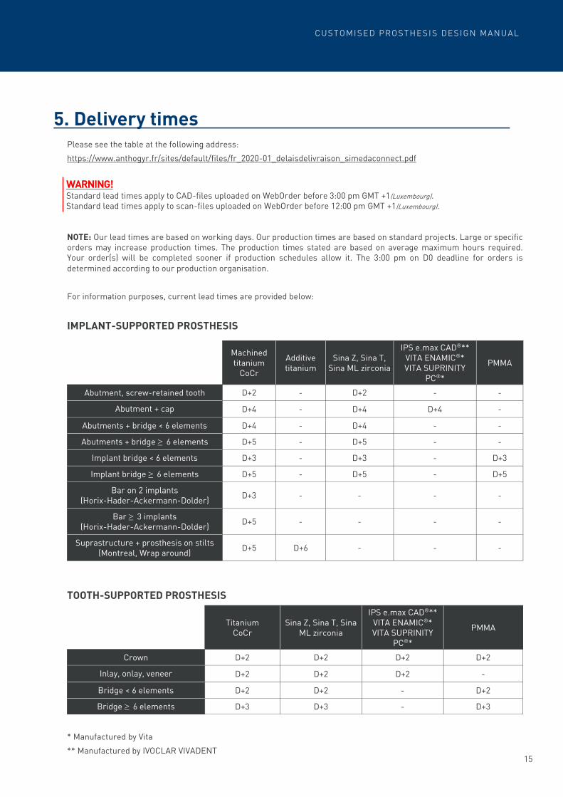
5. Delivery times Please see the table at the following address:
https://www.anthogyr.fr/sites/default/files/fr_2020-01_delaisdelivraison_simedaconnect.pdf
NOTE: Our lead times are based on working days. Our production times are based on standard projects. Large or specific orders may increase production times. The production times stated are based on average maximum hours required. Your order(s) will be completed sooner if production schedules allow it. The 3:00 pm on D0 deadline for orders is
determined according to our production organisation.
For information purposes, current lead times are provided below:
IMPLANT-SUPPORTED PROSTHESIS
TOOTH-SUPPORTED PROSTHESIS
* Manufactured by Vita
** Manufactured by IVOCLAR VIVADENT
WARNING! Standard lead times apply to CAD-files uploaded on WebOrder before 3:00 pm GMT +1(Luxembourg). Standard lead times apply to scan-files uploaded on WebOrder before 12:00 pm GMT +1(Luxembourg).
Machined titanium
CoCr
Sina Z, Sina T, Sina ML zirconia
IPS e.max CAD®** VITA ENAMIC®* VITA SUPRINITY
PC®*
PMMA Additive titanium
Abutment, screw-retained tooth D+2 D+2 - - -
Abutment + cap D+4 D+4 D+4 - -
Abutments + bridge < 6 elements D+4 D+4 - - -
Abutments + bridge ≥ 6 elements D+5 D+5 - - -
Implant bridge < 6 elements D+3 D+3 - D+3 -
Implant bridge ≥ 6 elements D+5 D+5 - D+5 -
Bar on 2 implants (Horix-Hader-Ackermann-Dolder)
D+3 - - - -
Bar ≥ 3 implants (Horix-Hader-Ackermann-Dolder)
D+5 - - - -
Suprastructure + prosthesis on stilts (Montreal, Wrap around)
D+5 - - - D+6
Titanium
CoCr Sina Z, Sina T, Sina
ML zirconia
IPS e.max CAD®** VITA ENAMIC®* VITA SUPRINITY
PC®*
PMMA
Crown D+2 D+2 D+2 D+2
Inlay, onlay, veneer D+2 D+2 D+2 -
Bridge < 6 elements D+2 D+2 - D+2
Bridge ≥ 6 elements D+3 D+3 - D+3

16
Technical Support will assist you with the installation of the Anthogyr and MPS implant platforms library on your
system.
Anthogyr SA Mersch offers training in digitalisation and modelling of implant-supported products. For more information,
contact Technical Support.
1. Explanations For the sake of clarity, we will call “Scanner Set” this set comprised of the following: - Laboratory scanner - User - Scan-adapter
- Model
The conditions for sending the digital workflow from the scanner are met when the following criteria are met:
→ Validated user training
→ Adequacy of scanner for type of restoration and quality of scan adapters
→ Implant library installed
Based on this validation, the laboratory may send all its multiple workflows and benefit from the Serenity® guarantee.
2. Terms and conditions The users of a “not yet validated” Scanner Set who submit a project via digital file (project meeting the previous
conditions) without master model to verify the accuracy of the implant platforms, will not be able to obtain guarantee of
passivity on their model or in the patient’s mouth.
The responsibility of the laboratory for the conditions of use of its scanner still applies and the quality of digitisation depends on the conditions of use and recalibration of the scanner, the quality of the scan-adapters used and the strict
observance of scanning operations.
3. Validity Scanner Set validation remains effective until the customer detects a case of non-passivity. After 2 complaints of non-
passivity, Anthogyr may request a new scanner validation process.
Validation of your scanner
WARNING! If the model received does not meet the Anthogyr warranty criteria, no inspection will be performed.
WARNING! Failure to fulfil these conditions may result in the production of faulty prostheses, according to the laboratory.

17
CUSTOMISED PROSTHESI S DESIGN MANUAL
EQUIPMENT REQUIRED
Use the laboratory scan-adapters according to the type of project: → SAA: single-unit prostheses.
→ SAO: multiple-unit protheses.
→ SA: single-unit and multiple-unit prostheses.
The digitisation and design of prostheses without sending the model require the use of the latest version of Anthogyr’s
scan-adapters and the validation of your scanner.
PROTOCOL
When positioning the scan-adapter, ensure the analogues are clean (no scanning spray), are free from signs of wear or
shock and are steady in the model.
Remove the soft tissue when positioning the scan-adapter.
Secure the scan-adapters with the pink screws supplied and the specific tightening tool (Ref. SATOOL) by applying a
moderate torque (for more information, please refer to the user leaflet (063SAKIT_NOT) IFU code: 152-27-SAA.
Digitisation
Scan-Adapter tightening tool Laboratory Scan-Adapter
OK NO
WARNING! For multiple-unit protheses, position scan-adapters on both the master model and the analogue. If the model includes reflecting areas, use a scanning spray to avoid compromising the digitisation. Avoid spraying the scan-adapters. Avoid spraying the analogues. Verify the correct positioning of the scan-adapter. The scan-adapter platform should be touching the analogue platform.

18
Perform the digitisation: → Calibrate the scanner.
→ Check the luminosity and height of the model.
→ Scan the required number of views.
→ Select the appropriate library for the implant platform.
For more details, please refer to the documentation received with the delivery of your system.
Perform the modelling according to your expectations and observing the design limits.
WARNING! The scanner should be placed on a steady surface, free from vibrations (e.g. a laboratory machining surface).
The scanner should be away from external light or heat sources. This can result in a loss of accuracy in the short or me-dium term.
Calibration is required on a daily basis before the first digitisation. After turning on the scanner, wait 15 to 20 minutes before calibration. Do not add any views on the scan adapter. For projects such as bridges on customised abutments, multi casts should preferably not be used. Scan the project by separating the abutments (preparation of a sectioned model).
19
CUSTOMISED PROSTHESI S DESIGN MANUAL
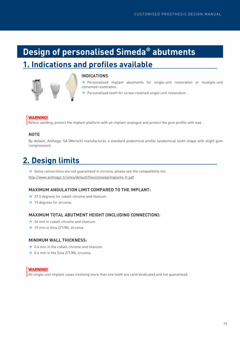
1. Indications and profiles available
INDICATIONS
→ Personalised implant abutments for single-unit restoration or multiple-unit
cemented restoration.
→ Personalised teeth for screw-retained single-unit restoration .
NOTE
By default, Anthogyr SA (Mersch) manufactures a standard anatomical profile (anatomical tooth shape with slight gum
compression).
2. Design limits → Some connections are not guaranteed in zirconia, please see the compatibility list:
http://www.anthogyr.fr/sites/default/files/simeda/implants-fr.pdf
MAXIMUM ANGULATION LIMIT COMPARED TO THE IMPLANT:
→ 37.5 degrees for cobalt-chrome and titanium.
→ 15 degrees for zirconia.
MAXIMUM TOTAL ABUTMENT HEIGHT (INCLUDING CONNECTION):
→ 24 mm in cobalt-chrome and titanium.
→ 19 mm in Sina Z/T/ML zirconia.
MINIMUM WALL THICKNESS:
→ 0.4 mm in the cobalt-chrome and titanium.
→ 0.6 mm in the Sina Z/T/ML zirconia.
Design of personalised Simeda® abutments
WARNING! Before sanding, protect the implant platform with an implant analogue and protect the gum profile with wax .
WARNING! All single-unit implant cases involving more than one tooth are contraindicated and not guaranteed.

20
3. Specifications for customised abutments on
Axiom® BL & TL titanium base A. ABUTMENT OR SCREW-RETAINED ZIRCONIA TOOTH ON STRAIGHT
AXIOM® BL TITANIUM BASE
INDICATIONS
→ Customised Simeda® single-unit restoration in Sina Z/T/ML zirconia single-unit restoration on
titanium base with straight channel for Axiom® BL implant.
INFORMATION
→ The abutments are supplied attached to an Axiom® BL titanium base.
→ The single-unit screw-retained teeth are supplied unattached to the Axiom® BL titanium base.
→ Supplied with an Axiom® BL M1.6 screw.
→ Available in two diameters and several gingival heights:
B. ABUTMENT OR SCREW-RETAINED ZIRCONIA TOOTH ON STRAIGHT
AXIOM® TL TITANIUM BASE
INDICATIONS
→ Customised Simeda® Sina Z/T/ML zirconia single-unit restoration on titanium base with straight channel for Axiom®
TL implant.
INFORMATION
→ The abutments are supplied attached to an Axiom® TL titanium base.
→ The single-unit screw-retained teeth are supplied not attached to the Axiom® TL titanium base.
→ Supplied with an Axiom® TL M1.6 screw.
→ Available in two platform diameters: N (Ø4.0) /R (Ø4.8):
∅ 4.0 ∅ 5.0
HG (mm) 1.2 1.5 2.5 3.5 1.5 2.5 3.5
Sandblast compatible part refer-
ence
OPFLEX403 OPFLEX413 OPFLEX423 OPFLEX433 OPFLEX513 OPFLEX523 OPFLEX533
N (∅ 4.0) R (∅ 4.8)
Sandblast compatible part reference TFLEX-N TFLEX-R

21
CUSTOMISED PROSTHESI S DESIGN MANUAL
4. Specifications for AxIN® screw-retained teeth
INDICATIONS
→ Customised Simeda® Sina Z/T/ML zirconia single-unit restoration on AxIN® titanium
base with up to 25° Angulated Access.
INFORMATION
→ On Axiom® BL implant or on Axiom® TL implant.
→ Screw-retained restoration with no cement or adhesive.
→ On Axiom® BL implants, the AxIN® solution is contraindicated in the molar sector on an
AxIN® base 1.5 mm thick, with a Ø4.0 and Ø5.0 mm. diameter
→ The AxIN® solution is contraindicated in the molar sector on a TL implant with a 1.5 mm
neck height on platforms N and R.
NOTE: The AxIN® prosthesis is supplied with its permanent base and screw.
Handle AxIN® bases carefully.
A. DIGITISATION OF THE MASTER MODEL
EQUIPMENT REQUIRED
→ The screw supplied with the implant analogue should not be used in case of an AxIN® restoration.
PROTOCOL
→ Digitalise the platform using the Scan Adapter with an Anthogyr SA Mersch approved laboratory scanner by selecting
the appropriate library.
B. PROSTHESIS DESIGN
→ Design the abutment with an open CAD software or with a wax-up:
- Angulated access up to 25°
- Minimum height of the zirconia crown on an AxIN® base: 4.9 mm
- Minimum diameter of the zirconia crown on an AxIN® base: 4.5 mm
C. PREPARATION OF THE PROSTHESIS
Please see the Axiom® Multi level® prosthesis manual, available on the website ifu.anthogyr.com (search code: AXIN152-27-B41, for example).
For Axiom® TL For Axiom® BL
Scan-Adapter tightening tool SATOOL-01
Laboratory Scan-Adapter 152-27-SAA
Implant analogue TA100-N / TA100-R
Implant analogue OPIA100
Laboratory Scan-Adapter 156-0X-SAA

22
1. Indications and profiles available
INDICATIONS
→ Implant bridge designed to be ceramic coated directly or covered with single-unit crowns for each tooth.
PROFILES AVAILABLE
*The anatomical implant bridge design in Zirconia Sina -Z (Z1) is not recommended for aesthetic reasons, please prefer
a realization in Sina-T (Z2) or Sina-ML (Z3).
Possibility of creating: → emergence profiles at the implant level
→ lingual retainers
→ occlusal rests
→ ceramic supports around the screw channels
→ angulated screw channels for specific connections
For cobalt-chrome bridges, please refer to the instructions “Technical properties of the Simeda® cobalt-chrome alloy
and recommendations for ceramic coating” available on the Anthogyr website.
Design of Simeda® implant bridges
Thimble Crown
→ Implant bridge with preparation for single-unit cemented crowns
Implant bridge
→ Implant bridge for the homothetic reduction of the prosthetic project
Anatomical implant bridge*

23
CUSTOMISED PROSTHESI S DESIGN MANUAL
2. Design limits
LENGTH OF PONTICS :
→ Extension length: e ≤ 11 mm (all materials).
→ Length of internal pontics: p ≤ 35 mm for metal; p ≤ 21 mm for Sina Z/T/ML zirconia.
MINIMUM WALL THICKNESS :
→ 0.5 mm for cobalt-chrome and titanium.
→ 0.6 mm in Sina Z/T/ML zirconia.
MINIMUM TRANSVERSAL CONNECTOR SECTIONS (ALL MATERIALS):
→ Front teeth: up to 21 mm: 9 mm²,
over 21 mm: 12 mm².
→ Back teeth: metal: 9 mm², zirconia: 12 mm².
MAXIMUM HEIGHT OF THE IMPLANT BRIDGE:
→ 24 mm in cobalt-chrome and in titanium.
→ 19 mm in Sina Z/T/ML zirconia.
Implant platforms
e
p
WARNING! The bi-maxillary zirconia bridges are contraindicated and not guaranteed.
24
3. Specifications for customised prostheses with
inLink® connection
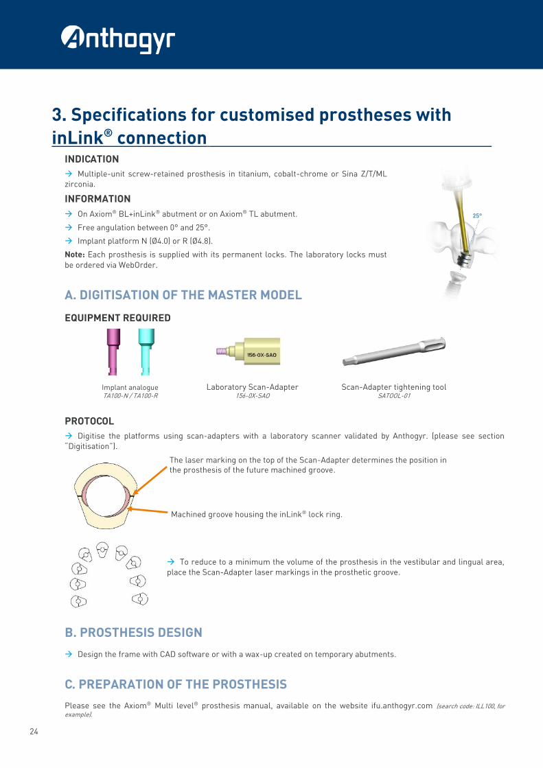
INDICATION
→ Multiple-unit screw-retained prosthesis in titanium, cobalt-chrome or Sina Z/T/ML
zirconia.
INFORMATION
→ On Axiom® BL+inLink® abutment or on Axiom® TL abutment.
→ Free angulation between 0° and 25°.
→ Implant platform N (Ø4.0) or R (Ø4.8).
Note: Each prosthesis is supplied with its permanent locks. The laboratory locks must
be ordered via WebOrder.
A. DIGITISATION OF THE MASTER MODEL
EQUIPMENT REQUIRED
PROTOCOL
→ Digitise the platforms using scan-adapters with a laboratory scanner validated by Anthogyr. (please see section
“Digitisation”).
→ To reduce to a minimum the volume of the prosthesis in the vestibular and lingual area,
place the Scan-Adapter laser markings in the prosthetic groove.
B. PROSTHESIS DESIGN
→ Design the frame with CAD software or with a wax-up created on temporary abutments.
C. PREPARATION OF THE PROSTHESIS
Please see the Axiom® Multi level® prosthesis manual, available on the website ifu.anthogyr.com (search code: ILL100, for example).
The laser marking on the top of the Scan-Adapter determines the position in the prosthesis of the future machined groove.
Machined groove housing the inLink® lock ring.
Laboratory Scan-Adapter 156-0X-SAO
Scan-Adapter tightening tool SATOOL-01
Implant analogue TA100-N / TA100-R

25
CUSTOMISED PROSTHESI S DESIGN MANUAL
4. Specifications for customised prostheses with
Multi-Unit Angulated Access INDICATION
→ Multiple-unit screw-retained prosthesis in titanium, cobalt-chrome or Sina Z/T/ML
zirconia.
INFORMATION
→ Possible screw channel angulation at 0°/10°/15°/20°/25°
→ 2 platform diameters: N: Ø4.0 / R: Ø4.8 for Multi Unit Axiom® BL abutment
→ MPS Platform: please see the implant compatibility list.
Note: For any prostheses supplied with at least one angulated screw channel, use Angulated Access permanent screws for all screw channels and a cylindrical prosthetic
ancillary.
A. DIGITISATION OF THE MASTER MODEL
EQUIPMENT REQUIRED
PROTOCOL
→ Digitise the platforms using scan-adapters with a laboratory scanner validated by Anthogyr. (please see section
“Digitisation” and the implant compatibility list for MPS platforms).
B. PROSTHESIS DESIGN
→ Design the frame with CAD software or with a wax-up created on temporary abutments.
C. PREPARATION OF THE PROSTHESIS
Note : Each prosthesis is supplied with a gripper and its own permanent screw.
The laboratory screws must be ordered via WebOrder.
Please refer to the instructions “Technical properties of the MUAA screw” or to the instructions on the Multi Unit
angulated access channels available on the website ifu.anthogyr.com (search code: MUAA140, for example).
WARNING! The permanent prosthetic screws and the gripper are intended solely for the use of the practitioner.
Scan-Adapter tightening tool SATOOL-01
Laboratory Scan-Adapter 151-03-SAO / 151-04-SAO
Implant analogue MUNA100 / MUA100

26
1. Indications and profiles available
INDICATIONS
→ Preparation of a fixed resin prosthesis on machined or additive titanium superstructure.
NOTE: clips or female parts are not supplied by Anthogyr.
PROFILES AVAILABLE
Design of superstructures type Simeda® implant
stilt
Profiles available Name Design option
Montréal
superstructure Retention
Gingival/lingual retainer
Wrap-around
superstructure Retention
Canada Superstructure
(T profile)
Retention or horizontal drilling
Gingival retainer
Polished surface
Wrap-around superstructure
Montréal superstructure Canada Superstructure
(T profile)
WARNING! To have a mucosal contact or a slight gingival compression, a model should be made with soft tissue on the entire con-tact surface, otherwise a 0.3 mm space will be applied.
Additive titanium
Surface available Rough Textured

27
CUSTOMISED PROSTHESI S DESIGN MANUAL
Possibility of creating: → emergence profiles at the implant level.
→ lingual retainers.
→ occlusal rests.
→ angulated screw channels for specific connections.
→ a rough or textured surface (in additive titanium only)
2. Design limits
MINIMUM SURFACE SECTION:
→ 12 mm² or minimum 4 mm diameter.
LENGTH OF PONTICS :
→ p ≤ 46 mm
EXTENSION LENGTH:
→ In case of a Wrap-Arounds bar: e ≤ 30 mm.
→ In case of a Montréal bar: e ≤ 40 mm.
→ In case of a Canada bar (T profile): e ≤ 40 mm.
SPECIFICATIONS FOR ADDITIVE TITANIUM PROSTHESES:
→ In case of a superstructure with textured surface, a 0.3 mm maximum overlay is applied on the textured area.
3. Specifications for customised Simeda® prostheses
with inLink® connection Please see page 24.
4. Specifications for customised prostheses with
Angulated Access Please see page 25.
Implant platforms
e
p
28
1. Implant bars for clips
A. INDICATIONS AND PROFILES AVAILABLE
INDICATIONS
→ Stabilisation of a removable prosthesis.
NOTE: clips or female parts are not supplied by Anthogyr.
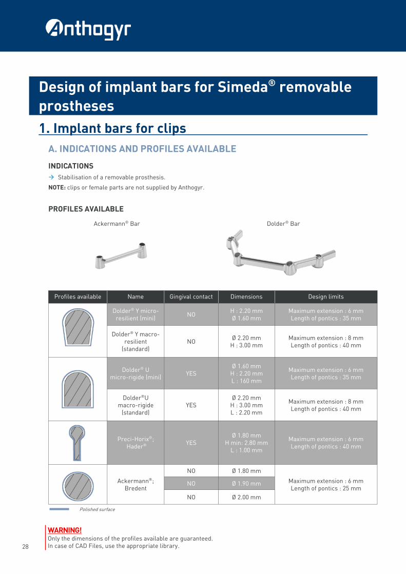
PROFILES AVAILABLE
Design of implant bars for Simeda® removable
prostheses
Ackermann® Bar Dolder® Bar
Profiles available Name Gingival contact Dimensions Design limits
Dolder® Y micro-resilient (mini)
NO H : 2.20 mm Ø 1.60 mm
Maximum extension : 6 mm Length of pontics : 35 mm
Dolder® Y macro-resilient
(standard) NO
Ø 2.20 mm H : 3.00 mm
Maximum extension : 8 mm Length of pontics : 40 mm
Dolder® U
micro-rigide (mini) YES
Ø 1.60 mm H : 2.20 mm L : 160 mm
Maximum extension : 6 mm Length of pontics : 35 mm
Dolder®U macro-rigide
(standard) YES
Ø 2.20 mm H : 3.00 mm L : 2.20 mm
Maximum extension : 8 mm Length of pontics : 40 mm
Preci-Horix®; Hader®
YES Ø 1.80 mm
H min: 2.80 mm L : 1.00 mm
Maximum extension : 6 mm Length of pontics : 40 mm
Ackermann®; Bredent
NO Ø 1.80 mm
Maximum extension : 6 mm Length of pontics : 25 mm
NO Ø 1.90 mm
NO Ø 2.00 mm
Polished surface
WARNING! Only the dimensions of the profiles available are guaranteed. In case of CAD Files, use the appropriate library.
29
CUSTOMISED PROSTHESI S DESIGN MANUAL
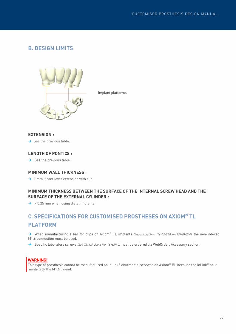
B. DESIGN LIMITS
EXTENSION :
→ See the previous table.
LENGTH OF PONTICS :
→ See the previous table.
MINIMUM WALL THICKNESS :
→ 1 mm if cantilever extension with clip.
MINIMUM THICKNESS BETWEEN THE SURFACE OF THE INTERNAL SCREW HEAD AND THE
SURFACE OF THE EXTERNAL CYLINDER :
→ > 0.25 mm when using distal implants.
C. SPECIFICATIONS FOR CUSTOMISED PROSTHESES ON AXIOM® TL
PLATFORM
→ When manufacturing a bar for clips on Axiom® TL implants (Implant platform 156-05-SAO and 156-06-SAO), the non-indexed
M1.6 connection must be used.
→ Specific laboratory screws (Ref. TS162P-2 and Ref. TS163P-2) must be ordered via WebOrder, Accessory section.
WARNING!
This type of prosthesis cannot be manufactured on inLink® abutments screwed on Axiom® BL because the inLink® abut-ments lack the M1.6 thread.
Implant platforms
e
p
30
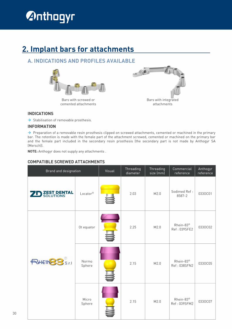
2. Implant bars for attachments
A. INDICATIONS AND PROFILES AVAILABLE
INDICATIONS
→ Stabilisation of removable prosthesis.
INFORMATION
→ Preparation of a removable resin prosthesis clipped on screwed attachments, cemented or machined in the primary bar. The retention is made with the female part of the attachment screwed, cemented or machined on the primary bar and the female part included in the secondary resin prosthesis (the secondary part is not made by Anthogyr SA
(Mersch)).
NOTE: Anthogyr does not supply any attachments .
COMPATIBLE SCREWED ATTACHMENTS
Bars with screwed or cemented attachments
Bars with integrated attachments
Brand and designation Visual Threading diameter
Threading size (mm)
Commercial reference
Anthogyr reference
Locator®
2.03 M2.0 Sodimed Ref :
8587-2 033OC01
Ot equator
2.25 M2.0 Rhein-83®
Ref : 039SFE2 033OC02
Normo Sphere
2.15 M2.0 Rhein-83®
Ref : 038SFN2 033OC05
Micro Sphere
2.15 M2.0 Rhein-83®
Ref : 039SFM2 033OC07

31
CUSTOMISED PROSTHESI S DESIGN MANUAL
COMPATIBLE CEMENTED ATTACHMENTS
COMPATIBLE INTEGRATED ATTACHMENTS
Brand and designation Visual Maximum length
(mm) Commercial
reference Anthogyr reference
Precis horix
5
Ceka® Ref : 1802
033OC72
7 033OC42
Precis vertex(Barre)
7 033OC61
Precis vertex(Bridge)
7 033OC62
Anchor M3
- Ceka® Ref : OL 0285 TI
033OC41
Vario Soft 3 (VS3)
7 Bredent® Ref :
430 0518 0 033OC53
Vario Kugel Snap (VKS)
7 Bredent® Ref :
430 0542 0 033OC54
Vario Soft 3 sv (VS3)
7 Bredent® Ref :
430 0518 0 033OC55
MK1
- MK1® Ref :
9600 033OC56
Brand and designation Visual Diameter of the
casing (mm) Commercial
reference Anthogyr reference
Titanium casing for micro Sphere
Ø1.60 Rhein-83®
Ref : 139KSFM 033OC06
Titanium casing for Normo Sphere
Ø1.60 Rhein-83®
Ref : 139KSN 033OC08
CEKA M2 (AXIAL-PRECI CLIX)
Ø2.0 Ceka® Ref : OL 0885 TI
033OC22
CEKA M3 (AXIAL-PRECI CLIX)
Ø3.0 Ceka® Ref : OL 0285 TI
033OC23

32
B. DESIGN LIMITS
EXTENSION LENGTH :
→ e ≤ 8 mm
LENGTH OF PONTICS :
→ p ≤ 35 mm
MINIMUM SECTIONS :
→ Rectangular profile = minimum 4 mm height and 2 mm width.
→ Circular profile = minimum 3 mm diameter .
C. SPECIFICATIONS FOR CUSTOMISED PROSTHESES ON AXIOM® TL
PLATFORM
→ When manufacturing a bar for attachments on Axiom® TL implants (Implant platform 156-05-SAO and 156-06-SAO), the non-
indexed M1.6 connection must be used.
→ Specific laboratory screws (Ref. TS162P-2 and Ref. TS163P-2) must be ordered via WebOrder, Accessory section. .
WARNING! This type of prosthesis cannot be manufactured on inLink® abutments screwed on Axiom® BL because the inLink® abut-ments lack the M1.6 thread.
Implant platforms
e
p

33
CUSTOMISED PROSTHESI S DESIGN MANUAL
1. Tooth-supported restorations
→ Crowns.
→ Copings and bridges with 2 to 14 elements.
→ Inlays / Onlays and veneers.
→ Available en Titanium, Cobalt chrome, Sina Z/T/ML zirconia, Vita ENAMIC®, Vita SUPRINITY® PC, IPS e.max® CAD*.
2. Model preparation → Use extra hard plaster without adding resin or polymer.
→ Casts should have no cast spacer.
→ To facilitate the preparation of the occlusion, have an opposite model that can easily be positioned on the master
model. (Please refer to the list of articulators on page 14).
→ Eliminate all small air bubbles from the plaster on the occlusal surface.
→ Prepare a cervical limit well cleared and easily identifiable.
→ The various elements of the master model should be easy to disassemble (Casts/Adjacent tooth), and must not be
subject to rotation or shifting.
→ The casts should be free from major undercuts or air bubbles, to be able to fit the framework.
3. Design limits LENGTH OF PONTICS
→ 35 mm for cobalt-chrome and titanium.
→ 21 mm in Sina Z/T/ML zirconia .
MAXIMUM EXTENSION
→ 10 mm (all materials).
WALL THICKNESS
→ 0.5 mm for cobalt-chrome and titanium.
→ 0.6 mm in Sina Z/T/ML zirconia.
MINIMUM CONNECTOR
→ 9.0 mm² for cobalt-chrome and titanium.
→ 12 mm2 in Sina Z/T/ML zirconia.
* Please refer to the instructions “Technical properties of the Sina Z/Sina T zirconia and Sina ML zirconia” and “Technical properties of the Simeda® cobalt-chrome alloy and recommendations for ceramic coating” available on the
Anthogyr website.
Design of tooth-supported prostheses
WARNING! The bi-maxillary zirconia bridges are contraindicated and not guaranteed.
34
NOTES

35
CUSTOMISED PROSTHESI S DESIGN MANUAL
NOTES

A Anthogyr SA
8, um Mierscherbierg L-7526 Mersch - Luxembourg Tél. +352 266 404 1 Fax +352 266 404 44
www.anthogyr.com
Photo credits: Anthogyr - All rights reserved - Actual products may vary Medical devices for use by dental professionals. Please read the instructions and user manuals thoroughly
MA
NU
EL
-CA
D_
EN
_N
OT
_A
V
ali
dit
y d
ate
: 2
02
0-1
2
HOW TO CONTACT TECHNICAL SUPPORT
Telephone: (+352) 266 404 1
Email: [email protected]
Web: www.anthogyr.com Rubrique Digital / Le Service en + / Support Technique