
Customer Premises Equipment (CPE) Market Adoption … · Of course, not all homes are the same. We...
23
Copyright © 2018 Telecom Infra Project, Inc. All rights reserved. Customer Premises Equipment (CPE) Market Adoption Requirements
Transcript of Customer Premises Equipment (CPE) Market Adoption … · Of course, not all homes are the same. We...

Copyright © 2018 Telecom Infra Project, Inc. All rights reserved.
Customer Premises Equipment (CPE) Market Adoption Requirements

Copyright © 2018 Telecom Infra Project, Inc. All rights reserved.
Copyright © 2018 Telecom Infra Project, Inc. All rights reserved.
The Telecom Infra Project logo is a trademark of Telecom Infra Project, Inc. (the “Project”) in the United States or other countries and is registered in one or more countries. Removal of any of the notices or disclaimers contained in this document is strictly prohibited.
The publication of this document is for informational purposes only. THIS DOCUMENT IS PROVIDED “AS IS,” AND WITHOUT ANY WARRANTY OF ANY KIND, INCLUDING WITHOUT LIMITATION, ANY EXPRESS OR IMPLIED WARRANTY OF NONINFRINGEMENT, MERCHANTABILITY, OR FITNESS FOR A PARTICULAR PURPOSE. UNDER NO CIRCUMSTANCES WILL THE PROJECT BE LIABLE TO ANY PARTY UNDER ANY CONTRACT, STRICT LIABILITY, NEGLIGENCE OR OTHER LEGAL OR EQUITABLE THEORY, FOR ANY INCIDENTAL INDIRECT, SPECIAL, EXEMPLARY, PUNITIVE, OR CONSEQUENTIAL DAMAGES OR FOR ANY COMMERCIAL OR ECONOMIC LOSSES, WITHOUT LIMITATION, INCLUDING AS A RESULT OF PRODUCT LIABILITY CLAIMS, LOST PROFITS, SAVINGS OR REVENUES OF ANY KIND IN CONNECTION WITH THE SUBJECT MATTER OF THIS AGREEMENT.

Copyright © 2018 Telecom Infra Project, Inc. All rights reserved.
Table of Contents 1 Introduction ...................................................................................................................... 4
2 Morphologies and Deployment Aspects ......................................................................... 4
2.1 Sub-urban and Selected Rural Areas ....................................................................... 8
2.2 Urban ....................................................................................................................... 9
2.3 Customer & Market Requirements .......................................................................... 9
2.3.1 The Need for Gigabit Internet Speed and Target Groups Today ....................... 9
2.3.2 Customer-related Aspects to Consider for CPE Solutions ................................ 10
2.3.3 Insights on CPE Concepts Based on Qualitative User Studies .......................... 11
2.3.4 Installation, Operation and Service Aspects ...................................................... 13
2.4 Operator Requirements ......................................................................................... 15
2.4.1 ODU/CN Features .............................................................................................. 16
2.5 Technical Requirements ......................................................................................... 18
2.5.1 Outdoor Equipment ........................................................................................... 18
2.5.2 How to Bridge the Wall ..................................................................................... 20
3 Conclusions and Recommendations .............................................................................. 22
Annex A: References ............................................................................................................. 23

Copyright © 2018 Telecom Infra Project, Inc. All rights reserved.
1 Introduction Supplying high-speed Internet to a country for example of the size of Germany is a major undertaking. On our way to becoming a gigabit society, every household has to be equipped with broadband Internet access. The demand for future gigabit speeds will exist everywhere, even in rural areas. Flexible solutions such as mmWave 60 GHz can support a faster rollout. Millimeter wave (mmWave) wireless technology can transmit data from a central point, where you have fiber or other connections, to the customer’s home. The end-customer is connected to the gigabit data network using a LAN connection or via Wi-Fi. The scope of this technical document is Fixed Wireless Access (FWA) using unlicensed mmWave spectrum. Specifically, it aims to shed light on the different installation options and bottlenecks for Terragraph Client Nodes. Terragraph is a 60GHz multi-hop, multi-point wireless distribution network1 .The Client Node (CN) is the equipment on which the customer premise that enables the transmission to the house and into the house. Distribution across the home is an important aspect, as highlighted below, but not the focus of the current document. To maintain consistency with traditional wired technologies in Fixed Networks, in this document we refer to the Client Node as the Customer Premise Equipment (CPE).
2 Morphologies and Deployment Aspects The objective of the mmWave working group is to increase the speed of adoption of Gigabit broadband access services. The holy grail of such broadband access is the use of end-to-end fiber. However, the capital expenditure needed for such a network has proven prohibitively high, leading to limited deployment, which focuses on attractive use cases, such as the inner part of recently-new cities. Furthermore, fiber deployment takes time. It has been calculated that it would take approximately 20 years from deployment until the last home in Belgium would be connected. Luckily, technologies have been developed that

Copyright © 2018 Telecom Infra Project, Inc. All rights reserved.
leverage existing media, such as G.fast, DOCSIS 3.1. These are very attractive solutions, especially for an incumbent operator with, by definition, an existing infrastructure. However, there is a medium that is partially accessible to all: the air. We say partially, since a lot of the spectrum has been licensed and tightly regulated. Today, a lot of the most attractive spectrum has been already allocated. This has led the wireless industry to increase the spectral efficiency in the attractive, but narrow, sub-6 GHz band, and, at the same time, move towards higher bands with more intrinsic capacity at a shorter reach, such as mmWave. In this band, the 60 GHz band has been regulated worldwide to be used for ISM application. The unlicensed 60 GHz FWA technology offers promising use cases, where it can complement a fiber roll-out and therefore accelerate a broadband roll-out to serve more customers with fiber-like speed in a shorter time. It can cover those areas, where the total cost of ownership (TCO) of fiber is negative. Typically, these areas are suburban areas, smaller cities or some selected rural areas with average home densities. Furthermore, it can be used to lower the TCO of fiber, where end-to-end fiber is economically viable. This is typically the case in urban environments. However, rural areas also contain small pockets of homes that are good candidates for mmWave FWA solutions when combined with a cost-effective long-distance backhaul, such as P2P microwave. It has been shown that mmWave technologies in selected neighborhoods offer a cost-effective alternative to two elements in the fiber network: the distribution network, and the drop. The distribution network is the network between two different POPs, and typically covers an area of 2-5 km2. As shown in multiple Terragraph field trials, a cloud-controlled mesh of wireless nodes can offer a cost-effective, yet high-performing alternative to a fiber rollout. The drop network denotes the part that connects the fiber distribution network to the home (typically this is a single fiber, between the last splitter and the home).

Copyright © 2018 Telecom Infra Project, Inc. All rights reserved.
In this document, we only focus on the drop aspect. The 60 GHz mmWave drop connection, consists of two pieces of active equipment: The access point (AP), and the Customer Premises Equipment (CPE). The document is further focused on the installation of the CPE. Given that the CPE contributes directly (1:1) to the Total Cost of Ownership (TCO) of the network per homes connected (as each connected home requires a CPE), it is of vital importance that both the CPE and its installation, are low-cost. The figure below shows that mmWave communication comes with its own challenges. Line of Sight (LOS) between the AP and CPE is needed to get a workable link budget, as we cannot count on diffraction to overcome the high losses incurred by obstacles. Furthermore, the antenna (at minimum) needs to be installed on the outside of the home, since the signal is attenuated severely by the outside wall, whatever building material is used.
This also implies that a CPE should consist of three individual building blocks:
1) Outdoor equipment, which needs to be hardened for weather. At minimum, the antenna, and its power amplifiers, are needed at this location.
2) Technology to bridge the wall 3) Indoor equipment. At minimum, the indoor equipment contains a (preferentially
wireless) gateway to distribute the broadband throughout the home.

Copyright © 2018 Telecom Infra Project, Inc. All rights reserved.
Of course, not all homes are the same. We can differentiate, based on morphology (urban, suburban, rural), housing (detached, semi-detached, closed), and number of living units a single building contains (Single dwelling unit (SDU); small multi-dwelling unit (small MDU); large multi-dwelling units (large MDU)). In the case of larger MDUs, flats (for example) might not have windows facing the street. Here we should also consider wireless-to-the-building (WTTB) as a solution in the case of serving customers in upper floors (>7).
As mentioned above, the CPE and its installation contribute directly to the TCO per household connected (HHC), which is driving the business case for operators. Therefore, installation should be cost-efficient, and straightforward. The ideal installation is “self-installation.” Within the International Telecommunication Union, self-installation is not only defined as an installation procedure without an on-site engineer; from the moment that an end-user needs a screw driver, the installation procedure is no longer considered self-install.
A wireless solution offers more flexibility and options for installation. However, the installation procedure must be independent of third parties such as homeowner's associations, neighbors, and landlords as the approval processes might be complex and time-consuming. This is especially true for cases of tenants and people living in MDUs. Moreover, the goal must be to provide solutions which are ready immediately, once set up.
Given the installation of outdoor equipment, and the safety regulations involved, also consider the concept of partial self-installation. Partial self-install could be where the service provider installs the outdoor unit and leaves the indoor unit for the consumer to connect. The connection would need to be simple and straightforward for the consumer. The benefit

Copyright © 2018 Telecom Infra Project, Inc. All rights reserved.
to the service provider is not having to schedule entry inside the consumer's home, saving significant time on the outdoor partial install.
2.1 Sub-urban and Selected Rural Areas Apartments without a view to the street/ground floor apartments One of the indirect requirements of assuming line-of-sight conditions is that both the access point and the CPE need to be installed at height. Otherwise, persons or vehicles can block the signal, leading to a poor user experience. It has been shown that putting up poles, dedicated for small cell deployment with a 100 m reach, destroys the business case. Therefore, it is important that the access point needs to be installed, using existing infrastructure, such as, lamp poles. The same holds for the CPE. Typically, three locations can be considered for the CPE installation:
• Roof • Window • Facade wall
The roof is the highest point, and therefore provides the best probability of line of sight towards an access point. However, it typically requires a professional install, and may sometimes be difficult to access. If an installer must climb on the roof there is also increased risk of damage to the roof that can increase installation and liability costs. Furthermore, a CPE here is located furthest away from the indoor data consumption, leading to a difficult indoor propagation environment. The window is an attractive mounting option, as it can be easily reached from the indoor by the end-customer, enabling self-installation (further on this later). However, studies have shown that people object to placing devices on their windows, given that it may obstruct their view and natural lighting indoor when the device exceeds a certain size. However, other installation sites such as the window sill are possible and appealing. With future developments, such as downsizing of the outdoor CPE and the modularization of the system can contribute to higher acceptance rates. Other options are walls or parts close to the facade. To enable installation from the indoors, it is recommended to place the CPE near a window. This option also allows flexibility in detached suburban homes to select the outside wall that has best line of sight probability towards one or more access points.

Copyright © 2018 Telecom Infra Project, Inc. All rights reserved.
2.2 Urban
For single-dwelling units, the reasoning above still holds and is more promising. In urban scenarios, MDUs are more likely to occur. MDUs provide many installation difficulties including:
• Permission by landlord or other owners, such as the ability to drill and mount devices on the building exterior
• Number of devices mounted (aesthetics) • Indoor cabling
2.3 Customer & Market Requirements
2.3.1 The Need for Gigabit Internet Speed and Target Groups Today Residential customers’ awareness and demand for gigabit-speed Internet is not fully pronounced so far and that it differs across countries. High-speed gigabit Internet is today only relevant for users who, due to their actual use, will genuinely need it and therefore are willing to pay for it. Others may express their general interest, but more for the sake of “just having it.” Internet bandwidth need and demand generally tends to increase in steps. This is a learned and observed behavior. The top driver of future demand is video streaming followed by simultaneous use of bandwidth-intensive services and cloud services. The latter requires higher upload rates compared to a more entertainment-oriented behavior. To shape the market for mmWave, different scenarios can be considered. Address the Most Demanding Customers:
• Focus on customers with a pronounced gigabit affinity but low(er) budget, e.g. students. This requires a minimal and simple solution with a focus on core functionality to be produced at low cost.
• Provide a solution for “Premium” customers who expect high quality and full options. These customers bring along a higher willingness to pay for good quality and full service. Target groups are, for example, modern digital customers (especially those working from home), small businesses (up to 9 employees), and families with teenagers (simultaneous use). Here, an integrated solution providing gigabit speed and additional options could be offered. Aspects such as aesthetics and service will play an important role.

Copyright © 2018 Telecom Infra Project, Inc. All rights reserved.
Connect all customers in an area: Provide an advanced solution which is upgradable for customers who live in a gigabit rollout area but do not require full bandwidth initially due to their actual usage behavior. However, they are more convenience-oriented and thus may ask for more service. Most customers tend to increase their Internet bandwidth in steps anyway, so, they might be happy with an initial bandwidth of 200-300 Mbps and upgrade gradually.
Focus on closing white spots even at lower speed: This target group mainly comprises underserved customers/areas, e.g. <16 Mbps. The goal is to connect them fast with higher speeds via mmWave.
2.3.2 Customer-related Aspects to Consider for CPE Solutions
When it comes to CPEs and the acceptance of a related service, different aspects of a customer perspective must be considered.
• Reliability One of the most essential aspects from a customer view is a reliable Internet connection. Variations in performance might be accepted if the Internet connection is stable. In this context, it is necessary to verify continuous line of sight, as well as consider potential impacts to connectivity due to weather. This also reinforces the requirement of permanent power supply of the street lights to avoid drop outs.
• Security Protection against vandalism, especially on ground and first-floor premises is a topic that must be covered. Furthermore, since we consider a wireless solution, data security must be provided and trustfully communicated.
• Simplicity Self-installation is most preferred. This requires an easy installation procedure including good and self-explaining manuals. Please, if possible, do not drill holes.
• Aesthetics Appealing form and design when visible, and unobtrusive when integrated in existing solutions/devices. Customers may wish for adjustments that match house style and settings and simple solutions in-house, in addition to self-installation requirements. In general, a professional appearance is extremely important.
• Radiation As mmWave is a wireless technology, health issues due to radiation are an aspect that can become a serious topic.
o In the United States, the Federal Communications Commission, federal health and safety agencies such as the Environmental Protection Agency (EPA), the Food and Drug Administration (FDA), the National Institute for Occupational Safety and Health (NIOSH) and the Occupational Safety and Health Administration (OSHA) have been actively involved in monitoring and investigating issues related to RF exposure.2

Copyright © 2018 Telecom Infra Project, Inc. All rights reserved.
o mmWave 60 GHz technology is still in the early testing phase and is currently being trialed in different countries. It is still too early to say specifically whether and how many antennas a rollout will need in the future. mmWave 60 GHz is designed to be operated with low transmission power (under 10 watts Equivalent Isotropically Radiated Power (EIRP)), an important parameter in determining the strength of the generated electromagnetic fields. For mmWave, as for all other wireless applications, applicable statutory safety standards must be met.
o In Germany, for example, the committees responsible for this technology and the German legislature are convinced that the technology is safe provided these standards are met.
• Cost The acceptance is highly dependent on costs/prices. Customers are willing to pay a higher price for service, if bandwidth and stability are generally assured. In general, a shared solution is perceived as lower bandwidth which may lead to a lower price tolerance.
We have asked respondents how they perceive the overall idea of mmWave in combination with a client node. The feedback has been very positive. What they appreciate most compared to fiber to the home (FTTH) is the fact that no major construction measures are needed. They consider it a flexible and practical setup.
Due to different housing types and housing situations, they expect different CPE options and the possibility to continue using their existing home equipment (home gateway, router, etc.). For a market approach, highlighting the benefits of a faster and more flexible installation with less construction work would likely be embraced by consumers.
2.3.3 Insights on CPE Concepts Based on Qualitative User Studies There is no one-size-fits-all solution. Antenna solutions are highly dependent on the conditions on site, such as buildings, facade, window construction, trees, etc. Advising before purchase might be a key to success. This could furthermore help to clarify Line of Sight aspects at an early stage.
Different concepts and installation sites have been developed, presented and discussed in qualitative studies in Germany at Deutsche Telekom. Valuable insights could be gained for further improvements. See the figure of presented concepts

Copyright © 2018 Telecom Infra Project, Inc. All rights reserved.
Requirements that have been mentioned
§ Easy installation without structural work
§ The node must be hidden or designed to match the dwelling
§ Data security is essential
§ Health aspects
§ Protection against vandalism
§ A smart combination with Wi-Fi can be considered an opportunity
Below are some statements given as feedback on the different CPE solutions:
In general, it is incongruous to have a wireless solution delivering connectivity to the home, but then use cables in the house to connect to the home gateway. Indoor cabling is an

Copyright © 2018 Telecom Infra Project, Inc. All rights reserved.
issue. A smart integrated Wi-Fi solution as an add-on may provide better acceptance and support aspects of stability and indoor-coverage as well.
Based on the feedback, we will continue working on the following approaches:
2.3.4 Installation, Operation and Service Aspects
Installation
Easy installation in combination with self-installation still remains a critical topic. So far, we do not have experience in a real-life environment. Therefore, it needs to be tested in the next steps of investigation
To do this, easy to understand installation instructions are mandatory. Short videos have proven to be effective for other types of training and installation.
In case of more elaborate installations, landlord involvement is required which may cause time-consuming processes. However, for business customers the trend is towards 3rd party specialist installation to ensure aspects such as warranty. For owners, drilling holes in the facade and insulation can be a go/no-go criterion.

Copyright © 2018 Telecom Infra Project, Inc. All rights reserved.
Visibility of CPE
The idea of ‘Shy-Tech’ (i.e. hiding the solution in existing equipment such as outdoor lighting) is important when considering CPE installation and placement.
• In the house: Wi-Fi is a tidy and “modern” solution and renders traditional cable connections less relevant.
• If cable is the selected option, cable management must be simple and pragmatic. Cables out in the open have the feel of a temporary solution and collect dust.
• When possible, avoiding structural changes to the home is preferred Quality of Connection Wi-Fi quality and signal routing in-house are essential factors for the customers. They prefer not to have any loose and additional/unnecessary cables and wires at home if possible. Availability and LoS check Provide an easy tool - online or via sales agent - to check if WTTH can be provided and LOS is given. In this context it is best to advise customers on which type of CPE to choose and where best to mount it. For the topic of installation, service and maintenance further explorations and investigations are needed to get a clearer picture from a customer perspective. Below are first thoughts of how to define service options.

Copyright © 2018 Telecom Infra Project, Inc. All rights reserved.
2.4 Operator Requirements
As mentioned in the introduction, in this document, we refer to the Client Node (CN), as the Customer Premise Equipment (CPE). Technical parameters derived from today's customer gateways:
• 4 X 1 GE LAN Interface • 2.4 and 5 GHz Wi-Fi (802.11bgn ac + mesh) • DECT support + analogue telephony • USB
Prices differ across Operators and solution type. Service to be supported:
• high speed internet • VoIP - including support at least of 4 QoS classes (Voice, low delay, Low loss, best
effort) • IP TV - IP multicast, V-LAN support • Smart Home integration
Operation CPE must be accessible and manageable, especially by the Operator and equipment vendors. Identified below are cases where manageability is critical.
• Operator

Copyright © 2018 Telecom Infra Project, Inc. All rights reserved.
o The Operator’s configuration system must have access to the outdoor unit (ODU), however manageability of the indoor unit can be controlled through the indoor CPE vendors’ cloud/overlay solution.
o Defined API to Operators' systems (OSS / IT). • Equipment Vendors
o The equipment vendors require access to the unit, either in single-box (where baseband is located outside of the home) or multi-box solution (where the entire CPE is dismantled, and the baseband resides in the CN and the Radio Frequency Integrated Circuit (RFIC) and antenna reside outside i.e. an Active Antenna). The multi-box solution is the more power-efficient option.
2.4.1 ODU/CN Features We need to distinguish between the current service architecture - the mainstream uses L2 ethernet based access between the customer premises equipment and the network gateway - and a mid- and long-term future service architecture that will use L3 based (with IPv6 transport) access. Existing Service Architecture Many, if not all, service providers use L2 access networks with virtual circuits (VLANs, PPPoE sessions, IPoE sessions). This requires ethernet transport functionality in the mmWave network. With the CN being the last hop of this network, the L2 transport function must be realized here. Also, it is worth noting that this setup doesn't make use of the network's ability to route CPE-to-CPE traffic on the shortest path.
• Transparent ethernet transport (both unicast and multicast destinations) with support for 802.1Q VLAN tags
• Support for queueing based on 802.1p CoS/IP DSCP (if exposed) • Location insertion of DHCP option 82 / PPPoE intermediate agent • Ethernet cable continuity testing procedure (similar as RTCT) • Remote management
Mid- and Long-term Service Architecture Service creation - with regards to Internet access - is moved from the operator’s network near to the subscriber and is done in the ODU. This includes IPv6 address management. We still need to support IPv4 based access, but the responsible component (IP L3 AFTR/tunnelling) shall be either part of the indoor CPE or the end devices (i.e. user equipment (UE)). For this scenario we will ultimately focus on a single routed connection to
IPv6
IPv4
CNCPE D
NDN
60GHzbackhaul
customer premises
IPv6IPv6
IPv4
Nx10G Internet1G
AFTR
OTT Video
OTT Voice
OTT messaging
Router
operator domain

Copyright © 2018 Telecom Infra Project, Inc. All rights reserved.
the Internet, and all other services are delivered using a network-agnostic way (e.g. over-the-top).
• IPv6 address assignment via SLAAC or DHCPv6 • IPv6 prefix-delegation • Support for queueing based on IPv6 Traffic class • Ethernet cable continuity testing procedure (similar as RTCT) • Accounting of allocated IPv6 address space via RADIUS/DIAMETER/etc • Remote management
IDU/CPE Features In general the indoor unit should be just a “regular” home router with gigabit-ethernet uplink. The idea of having a commodity device as indoor CPE aims for faster adoption and cutting the costs on the subscriber side. In the current - L2 focused - service architecture the CPE shall support the following features:
• DHCPv4 client and server & PPPoE client • DHCPv6 PD client for dual-stack access • IEEE802.1Q VLAN support • IGMP proxy & IGMP snooping • Analogue telephony functions (Analog Telephone Adapter (ATA), if required by
operator) • Traffic classification / marking / bandwidth management • Remote management (if used for VoIP & MC)
As for the mid- and long-term future plans, we can safely exclude legacy features like ATA and multicast support, and VLAN support on the uplink. Instead, AF translation specific features shall be supported in the CPE:
• DHCPv6 client, DHCPv4 server • LWAFTr / map-E / DS-Lite - to extend the lifetime of IPv4 only devices • Remote management (if operated by the service provider)
It is desirable for the IDU to support PoE out (af/at compliant with up to 10-12W power) in order to power the ODU using a single ethernet cable - but in general PoE injectors of this
Copyright © 2018 Telecom Infra Project, Inc. All rights reserved.
wattage are very affordable and are widely available - thus the electricity for the client node (CN) can be supplied without involving the CPE.
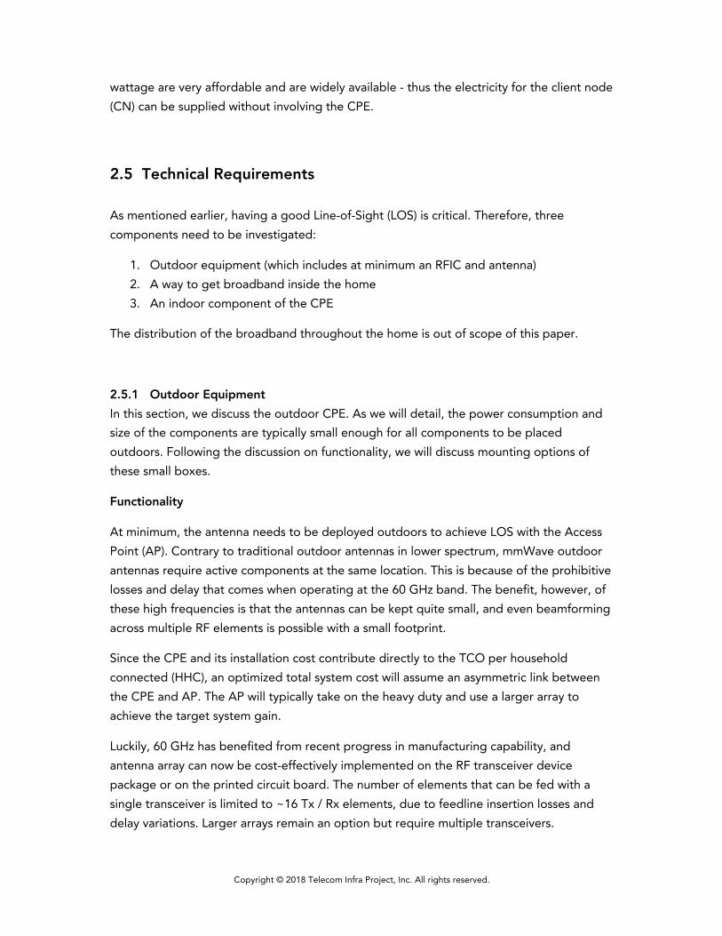
2.5 Technical Requirements As mentioned earlier, having a good Line-of-Sight (LOS) is critical. Therefore, three components need to be investigated:
1. Outdoor equipment (which includes at minimum an RFIC and antenna) 2. A way to get broadband inside the home 3. An indoor component of the CPE
The distribution of the broadband throughout the home is out of scope of this paper.
2.5.1 Outdoor Equipment In this section, we discuss the outdoor CPE. As we will detail, the power consumption and size of the components are typically small enough for all components to be placed outdoors. Following the discussion on functionality, we will discuss mounting options of these small boxes.
Functionality
At minimum, the antenna needs to be deployed outdoors to achieve LOS with the Access Point (AP). Contrary to traditional outdoor antennas in lower spectrum, mmWave outdoor antennas require active components at the same location. This is because of the prohibitive losses and delay that comes when operating at the 60 GHz band. The benefit, however, of these high frequencies is that the antennas can be kept quite small, and even beamforming across multiple RF elements is possible with a small footprint.
Since the CPE and its installation cost contribute directly to the TCO per household connected (HHC), an optimized total system cost will assume an asymmetric link between the CPE and AP. The AP will typically take on the heavy duty and use a larger array to achieve the target system gain.
Luckily, 60 GHz has benefited from recent progress in manufacturing capability, and antenna array can now be cost-effectively implemented on the RF transceiver device package or on the printed circuit board. The number of elements that can be fed with a single transceiver is limited to ~16 Tx / Rx elements, due to feedline insertion losses and delay variations. Larger arrays remain an option but require multiple transceivers.

Copyright © 2018 Telecom Infra Project, Inc. All rights reserved.
The total array size is determined by the antenna element structure and spacing. If the antenna is steerable in both the horizontal (azimuth) plane and vertical (elevation) plane, antenna elements should be spaced 2.5 mm, which is half of the wavelength. As an example, an 8x2 element array can be as small as 20 mm x 5 mm. This array may double in size when receive and transmit chains use separate elements. This need not be the case, as the TDD nature allows re-use, but this requires a switch, which incurs additional loss.
Given the outdoor equipment needs powering through the wall, it is interesting to highlight that the power consumption of a 60 GHz transceiver is quite low, ranging from 2 W to 6 W (approximately).
While theoretically not needed, the baseband and network processor are preferentially placed in the same equipment as the RF subsystem. Since these two components each consume less than to 10 W (depending on implementation), feeding an entire CPE outdoors remains feasible with Power over Ethernet (PoE) as we will detail below.
Mounting
Certain constraints need to be met, when mounting equipment outdoors. First, the equipment needs to be mounted safely. Since we aim for low operational expenditure (OPEX) cost, the equipment can be expected to remain at the installed location for a decade. However, removing the equipment should also be straightforward to allow people to move or to switch operators. Preferably, the installation of the equipment should allow self-install, or when this cannot be achieved, the installation duration should be as short as possible.
As highlighted above, there is no one-size-fits-all solution. A good rule-of-thumb is to evaluate the opportunities offered by the property. Some (non-exhaustive) examples can be found below:
1) Rooftop
Rooftops are highly desirable assets from a communication point of view. This is certainly the case for flat rooftops that allow easy access. The most common place to find these are MDUs in dense urban areas. The benefit of rooftop-mounted antennas in an MDU is that bridging the wall tends to be straightforward, as cables can be pulled in the elevator shaft. Challenges relate to arrangements with landlords (if there is one) and how the broadband is brought into the individual apartments.
2) Wall
The wall is the most obvious outdoor part of a property. To achieve good LOS, the outdoor antenna needs to be placed at height (first floor and above). Preferably, the installation should be done from the inside-out. The

Copyright © 2018 Telecom Infra Project, Inc. All rights reserved.
obvious challenge with this type of installation is how the broadband can be transferred across the wall.
3) Window
Street-facing windows are also typical features that offer good LOS conditions with similar challenges as the wall (how to bring broadband inside). The benefits of a window are that inside-out installation can be easily achieved, and that the broadband is typically injected in a place where it is consumed. The downside is that window-mounted CPEs are not considered attractive by users, as they interfere with the window’s main objective of letting sunlight enter the building.
4) Existing communication infrastructure
If present, existing infrastructure is a great place for an additional mmWave CPE. Television, aerial antennas, and satellite dishes are prime examples, as they are typically located on the roof or balcony and can provide a direct LOS for mmWave signals. These existing antennas are also already connected with cables, that can be re-used to bring the broadband inside of the home.
Many more options exist, such as house lights and rain gutters, each with their own pros and cons.
2.5.2 How to Bridge the Wall
Since we have identified the need for active components, both power and data will need to be fed from and to the outdoor equipment. Two main categories exist: wired and wireless. Each category has several options. For instance, wired installations can differ, based on brownfield conditions such as re-use of existing communication infrastructure. Likewise, wireless installations can differ in efficiency, based on the material the power and data is fed through.
Wired Installation
When using a wire in greenfield, Ethernet is the most obvious choice to bring power and data over a CAT5e cable to the outdoor equipment. As highlighted above, it is feasible to power the outdoor equipment with Power-over-Ethernet (PoE). Which PoE class to use varies with implementations. However, as shown in the table below, the granularity of the PoE classes is sufficiently high to allow a near-optimal choice. The most important column is the PD Input Power. Based on the discussion above, we should expect to see PoE class 4 or 5 to power the outdoor equipment.
Class Number
PSE Output Power (W)
PD Input Power (W)
PD Type
Cable Length
Power Over
VPSE (Min)
Standard

Copyright © 2018 Telecom Infra Project, Inc. All rights reserved.
0 15.4 12.95 1 100m 2 pairs 44V/50V IEEE802.3af 1 4 3.84 1 100m 2 pairs 44V/50V
2 7 6.49 1 100m 2 pairs 44V/50V
3 15.4 12.95 1 100m 2 pairs 44V/50V
4 30 25.5 2 100m 2 pairs 44V/50V IEEE802.3at 5 45 40 3 100m 2 pairs 50V
6 60 51 3 100m 4 pairs 50V IEEE802.3bt 7 75 62 4 100m 4 pairs 52V
8 90 73 4 100m 4 pairs 52V
The most common alternative to Ethernet in brownfield is a coaxial cable. Power delivery over coax has been commonplace for video surveillance and satellite video products. Integration of the power delivery should be feasible in the outdoor equipment, while an external power inserter would likely be needed indoors to supply the additional power to the mmWave outdoor unit.
For MDU rooftop installation, AC power should be readily available. Data distribution in this scenario can be achieved by running Ethernet to each apartment. Alternatively, cost-effective solutions exist to re-use existing cabling, such as G.fast for twisted pair or P2P coax, G.hn for twisted pair, powerline or P2MP coax, and MoCA for P2MP coax. The flexibility point of the wired infrastructure typically resides in the basement. Therefore, an Ethernet cable would need to be pulled down the elevator shaft to reach this flexibility point.
Wireless Installation
Data and power can also be transmitted wirelessly. For power, magnetic resonant charging is the only reasonable option available, given the large distance (> 10 cm) that needs to be bridged. This is something pure inductive coupling will not be able to achieve. Based on initial tests, magnetic resonant charging techniques have shown to be compatible with wireless data communication. Some low-E glass types may have an impact on wireless power efficiency and there is some concern about thermal heating of the embedded silver/aluminum metal particles in low-E glass. Research into these concerns is ongoing.

Copyright © 2018 Telecom Infra Project, Inc. All rights reserved.
The diagram above explains the wireless power design efficiency calculation. Efficiency and coil size are invariably linked in this type of implementation. First prototypes from partners in the TIP community have achieved 21 W wireless power transfer, with 70 % efficiency across a 5 cm thick low-E glass window with a 10 cm x 12 cm coil size. It is expected that further productization will increase power to 65 W with the same footprint. Alternatively, when keeping the same power transfer, the coil size in production could be decreased to 8 cm by 8 cm.
With respect to data transfer, RF solutions are the most universally applicable. Optical communication has also been investigated but is limited to window-mounted CPEs only. RF solutions in different spectra (from cm-wave to mm-wave) have shown to have been able to reach throughputs well more than 2 Gb/s throughput. This is in line with the mmWave drop. Typically, mm-wave solutions for data-through-wall implementations are expensive, given the high attenuation incurred by, e.g., low-E glass. Therefore, it is typically preferred to use other spectra, such as visible or sub-GHz.
3 Conclusions and Recommendations We are living in exciting times for the broadband community, as we are entering the Gigabit era. Exciting times, however, come with exciting problems, and mmWave communication is one of the solutions to address a core problem faced by operators: How to enter in this Gigabit era with a cost-effective approach. Relying on LOS allows mmWave units to be small, cheap and power-efficient, while beamforming removes the need to point the antennas. Further approaches to address temporary blocking of Line-of-Sight continue to be investigated within the TIP community, specifically by relying on the 5 GHz outdoor channel to enable backup capacity.
We intend to explore further installation and service options and test it in real-life environments. Therefore, we want to work on mockups and prototypes to gain more experience. Last but not least, cost aspects need to be validated in collaboration with other mmWave subgroups.
Copyright © 2018 Telecom Infra Project, Inc. All rights reserved.
Annex A: References [1] https://terragraph.com
[2] https://www.fcc.gov/general/radio-frequency-safety-0