Customer Expectations Document
78
imageRUNNER ADVANCE 8085 Customer Expectations Document Version 4 Systems & Technical Support Division Imaging Systems Group, Canon U.S.A., Inc.
Transcript of Customer Expectations Document

imageRUNNER ADVANCE 8085
Customer Expectations Document
Version 4
Systems & Technical Support Division Imaging Systems Group, Canon U.S.A., Inc.

Version 4 imageRUNNER ADVANCE 8085 Customer Expectations Document Page 2
Contents 1. Introduction ............................................................................................................. 6 2. Product Overview ................................................................................................... 6
2.1 Summary of Functions .................................................................................... 8 2.2 Differences between Version 1 and Version 2 ................................................ 9 2.3 High-Resolution Imaging System for Copied and Printed Images ................. 10 2.4 Image Stabilization Control ........................................................................... 10
2.4.1 Automatic Gradation Adjustment ..................................................... 11 2.4.2 Accurate Registration ...................................................................... 11
2.5 Professional Input/Output Accessories ......................................................... 12 2.6 Storage Capabilities ...................................................................................... 13
2.6.1 Mail Box ........................................................................................... 14 2.6.2 Advanced Box .................................................................................. 15 2.6.3 Network............................................................................................ 15 2.6.4 Memory Media ................................................................................. 16
2.7 Security Features .......................................................................................... 17 2.7.1 Device Authentication ...................................................................... 17 2.7.2 Data Security ................................................................................... 18 2.7.3 Document Security .......................................................................... 21 2.7.4 Network Security .............................................................................. 22
3. Machine Dimensions and Space Requirements ................................................ 23 3.1 Dimensions ................................................................................................... 23 3.2 Weight ........................................................................................................... 24 3.3 Installation and Service Space ...................................................................... 24
3.3.1 Minimum Space Requirements to Transport the Machine and Turn Hallway Corners .............................................................................. 25
3.3.2 Installation Space Diagrams ............................................................ 26 3.4 Recommended Floor Space Requirements .................................................. 30 3.5 Floor Structure Requirements ....................................................................... 30 3.6 Network Interface Connectivity ...................................................................... 31
4. Power/Electrical Requirements ........................................................................... 32 4.1 Power Requirements for the Main Unit and Optional Accessories ................ 32
5. Environmental Factors and Requirements ......................................................... 34 5.1 Temperature and Humidity Conditions .......................................................... 34 5.2 Temperature Gradient ................................................................................... 34 5.3 Ventilation ..................................................................................................... 35 5.4 Elevation Limitations ..................................................................................... 35 5.5 Lighting.......................................................................................................... 35 5.6 Sunlight ......................................................................................................... 35 5.7 Ammonia ....................................................................................................... 35

Version 4 imageRUNNER ADVANCE 8085 Customer Expectations Document Page 3
6. Specifications ....................................................................................................... 36 6.1 Main Unit ....................................................................................................... 36 6.2 Duplex Color Image Reader Unit-C1 ............................................................. 38 6.3 Paper Deck Unit-C1 ...................................................................................... 39 6.4 POD Deck Lite-A1 ......................................................................................... 39 6.5 Document Insertion Unit-K1 .......................................................................... 40 6.6 Paper Folding Unit-H1 ................................................................................... 41 6.7 Staple Finisher-D1 ........................................................................................ 42 6.8 Booklet Finisher-D1 ....................................................................................... 44 6.9 Booklet Finisher-F1 PRO .............................................................................. 47 6.10 Inner Booklet Trimmer-A1 ............................................................................. 51 6.11 Booklet Trimmer-D1 ...................................................................................... 51 6.12 Puncher Unit-BF1 .......................................................................................... 52 6.13 Puncher Unit-BB1 ......................................................................................... 52 6.14 Professional Puncher-C1 and Professional Puncher Integration Unit-B1 ...... 53 6.15 Card Reader-C1 ............................................................................................ 53 6.16 Copy Card Reader-F1 ................................................................................... 54 6.17 Super G3 FAX Board-AF1 ............................................................................. 54
7. System Options .................................................................................................... 55 7.1 PCL Printer Kit .............................................................................................. 55 7.2 PS Printer Kit ................................................................................................. 55 7.3 imagePASS-U1 ............................................................................................. 56 7.4 Direct Print Kit (for PDF/XPS Files) ............................................................... 57 7.5 Expansion Bus .............................................................................................. 57 7.6 Additional Memory Type B (512 MB) ............................................................ 57 7.7 IPSec Board .................................................................................................. 57 7.8 Universal Send Advanced Feature Set ......................................................... 57 7.9 Universal Send Security Feature Set ............................................................ 57 7.10 Universal Send Digital User Signature Kit ..................................................... 58 7.11 Secure Watermark ........................................................................................ 58 7.12 Document Scan Lock Kit ............................................................................... 58 7.13 HDD Data Encryption & Mirroring Kit ............................................................ 59 7.14 HDD Data Erase Kit ...................................................................................... 59 7.15 Encrypted Secure Print Software .................................................................. 59 7.16 Removable Hard Disk Drive Kit ..................................................................... 59 7.17 2.5 inch/80 GB HDD ...................................................................................... 60 7.18 2.5 inch/250 GB HDD .................................................................................... 60 7.19 Remote Operator's Software Kit .................................................................... 60 7.20 USB Device Port-A1 ...................................................................................... 60 7.21 Multimedia Reader/Writer-A1 ........................................................................ 60 7.22 Wireless LAN Board ...................................................................................... 61 7.23 Web Access Software ................................................................................... 61 7.24 Super G3 FAX Board-AF1 ............................................................................. 61 7.25 Super G3 2nd Line Fax Board-AF1 ............................................................... 61 7.26 Super G3 3rd/4th Line Fax Board-AE1 ......................................................... 62 7.27 Remote Fax Kit-A1 ........................................................................................ 62 7.28 FAX Board Attachment Kit-A1 ....................................................................... 62 7.29 Other imageRUNNER ADVANCE 8085 Main Unit Accessory Options ......... 62

Version 4 imageRUNNER ADVANCE 8085 Customer Expectations Document Page 4
8. Installation Review................................................................................................ 63 8.1 Installation Time ............................................................................................ 63 8.2 Customer Installation Responsibilities ........................................................... 64
9. Consumable Items ................................................................................................ 64 9.1 Usage Conditions .......................................................................................... 65 9.2 Consumable Parts ......................................................................................... 65
9.2.1 Estimated Life of Consumables ....................................................... 65 10. Toner Bottle Yields ............................................................................................... 65 11. Waste Toner Yields ............................................................................................... 66 12. Estimated Performance Standards ..................................................................... 66 13. Optimum Monthly Product Performance ............................................................ 67 14. Machine Productivity ............................................................................................ 68
14.1 Print Speed ................................................................................................... 68 14.2 Mixed Paper Weight Job Productivity ............................................................ 69 14.3 Paper and Toner Replacement ..................................................................... 69
15. Media Usage/Compatibility .................................................................................. 69 15.1 Media Characteristics by Media Library Parameters ..................................... 69 15.2 Paper Handling and Storage ......................................................................... 70 15.3 Paper Grain and Curl .................................................................................... 71 15.4 Note for Customers Who Cut Their Own Paper ............................................ 72 15.5 Media Feed Locations ................................................................................... 72 15.6 Paper Sizes and Feed Location Chart .......................................................... 75
16. Image Quality Capabilities ................................................................................... 76 16.1 Customer-Defined Image Quality Adjustments and Recommendations ........ 76
16.1.1 Adjust Image Quality Modes ............................................................ 77 16.1.2 Paper Type Management Settings .................................................. 77
17. Responsibility Matrix ............................................................................................ 78

Version 4 imageRUNNER ADVANCE 8085 Customer Expectations Document Page 5
IMPORTANT The purpose of this Customer Expectations Document is to explain the current features and capabilities of the imageRUNNER ADVANCE 8085, and provide customers information about what to expect before purchasing the machine. The information included in this document has been pulled from various sources, including product reference guides, service guides, and user manuals, as well as from the results from internal Canon testing. Specifications and other information contained herein may vary slightly, and in a non-material way, from actual device values, including those found in advertising and other printed matter. Part numbers, yield information, and specifications are subject to change without notice. Accordingly, the latest specifications for the machine may not be found in this document. As new information becomes available, this document will be revised. Canon authorized dealers can access the latest revision of this document from the Download Center page in the e-Support Web site (support.cusa.canon.com).
DISCLAIMER NEITHER CANON NOR ITS SUPPLIERS NOR ANY AUTHORIZED SERVICE PROVIDER SHALL BE LIABLE FOR PERSONAL INJURY OR PROPERTY DAMAGE (UNLESS CAUSED SOLELY AND DIRECTLY BY THE NEGLIGENCE OF CANON OR ANY AUTHORIZED SERVICE PROVIDER), LOSS OF REVENUE OR PROFIT, FAILURE TO REALIZE SAVINGS OR OTHER BENEFITS, EXPENDITURES FOR SUBSTITUTE EQUIPMENT OR SERVICES, LOSS OR CORRUPTION OF DATA, INCLUDING, WITHOUT LIMITATION, DATA STORED ON THE PRODUCT’S HARD DISK DRIVE, STORAGE CHARGES OR OTHER SPECIAL, INCIDENTAL OR CONSEQUENTIAL DAMAGES CAUSED BY THE USE, MISUSE OR INABILITY TO USE THE PRODUCT, REGARDLESS OF THE LEGAL THEORY ON WHICH THE CLAIM IS BASED AND EVEN IF CANON OR ITS SUPPLIERS OR ANY AUTHORIZED SERVICE PROVIDER HAS BEEN ADVISED OF THE POSSIBILITY OF SUCH DAMAGES. NOR SHALL RECOVERY OF ANY KIND AGAINST CANON OR ITS SUPPLIERS OR ANY AUTHORIZED SERVICE PROVIDER BE GREATER IN AMOUNT THAN THE PURCHASE PRICE OF THE PRODUCT CAUSING THE ALLEGED DAMAGE. WITHOUT LIMITING THE FOREGOING, THE PURCHASER ASSUMES ALL RISKS AND LIABILITY FOR LOSS, DAMAGE OR INJURY TO PERSONS AND THE PROPERTY OF THE PURCHASER OR OTHERS ARISING OUT OF THE POSSESSION, USE, MISUSE, OR INABILITY TO USE THE PRODUCT NOT CAUSED SOLELY AND DIRECTLY BY THE NEGLIGENCE OF CANON OR ANY AUTHORIZED SERVICE PROVIDER. Copyright 2011 by Canon U.S.A., Inc. All rights reserved. Product and company names used herein are, or may be, the registered trademarks or trademarks of their respective owners.

Version 4 imageRUNNER ADVANCE 8085 Customer Expectations Document Page 6
1. Introduction The Canon imageRUNNER ADVANCE 8085 Customer Expectations Document contains information about the features and capabilities of the Canon imageRUNNER ADVANCE 8085. This document should be used as part of the presale and pre-installation planning process to help clarify the requirements and responsibilities associated with supporting, owning, and operating the imageRUNNER ADVANCE 8085. It is also recommended that those interested in purchasing the imageRUNNER ADVANCE 8085 have, and familiarize themselves with, the information in this document prior to making their purchase.
2. Product Overview The Canon imageRUNNER ADVANCE 8085 brings the following capabilities to users in a high-volume, light-production office environment: • Speeds of up to 85 ppm (pages per minute) (LTR, Black-and-White). • Single pass duplex document feeder with two-sided black-and-white scanning
speeds of up to 200 ipm (images per minute), two-sided color scanning speeds of up to 100 ipm, and 300-sheet capacity.
• Large 10.4” high-resolution TFT screen (800 x 600 pixels), tilt-and-swivel control panel.
• Standard 80 GB hard disk drive, with an option to expand the machine’s memory to 250 GB.
• Finishing options, such as a staple or booklet finishers, professional puncher, document insertion unit, paper folding unit, inner booklet trimmer, or an external booklet trimmer.
• A maximum paper size of 13” x 19 1/4” is supported. Multiple paper sources, complemented by air-assisted feeding, can hold up to 7,700 sheets of paper for exceptional reliability.
• True 1,200 dpi printing at the engine’s rated speed. • Standard USB memory support. One USB port is on the control panel and can be
used for scanning, printing, or direct printing from a USB memory stick. One USB port is on the rear of the machine, and can only be used to attach a USB keyboard, third-party card reader, direct printing, or for servicing the machine.
• Induction Heating Technology for quick warm up times and first copy output times.
• Standard Universal Send and UFR II printing. • New pO (Precise Output) Toner Technology – A newly developed pO toner that
helps to reproduce images more accurately, and improves the evenness of solid black and halftones.

Version 4 imageRUNNER ADVANCE 8085 Customer Expectations Document Page 7
• Version 2 offers several feature enhancements over version 1, and is equipped with the ARCnet (Attachable Resource Computer Network) communication cable. The ARCnet communication cable is necessary to attach the new optional Booklet Finisher-F1 PRO to the V2 engine. The Booklet Finisher-F1 PRO offers improved finishing speeds compared to the optional Booklet Finisher-D1.
• The Booklet Finisher-F1 PRO and Booklet Trimmer-D1 cannot be purchased separately. They can only be purchased as part of the V2 engine.

Version 4 imageRUNNER ADVANCE 8085 Customer Expectations Document Page 8
2.1 Summary of Functions
Function imageRUNNER ADVANCE 8085 Print Speed (LTR) B&W 85 ppm Scan Speed (LTR, 300 dpi)
B&W 2-Sided: 200 ipm, 1-Sided: 120 ipm Color 2-Sided: 100 ipm, 1-Sided: 85 ipm
DADF Standard Single Pass Duplex DADF Capacity 300 sheets (20 lb bond (80 g/m²)) Engine Resolution 1,200 x 1,200 dpi Gradations 256 levels
Paper Size Min 5 1/2” x 7 1/8”*1, 4” x 5 7/8”*2, 4” x 7 1/8”*3 Max 13” x 19 1/4”
Paper Weight Drawers 14 lb bond to 80 lb cover (52 to 220 g/m²) Multi-Purpose Tray 14 lb bond to 140 lb index (52 to 256 g/m²)
HDD Capacity Standard 80 GB, Maximum 250 GB
Printer Memory Main Controller 1: 1.5 GB Standard Main Controller 2: 2 GB Maximum
Copy Standard
Store
Mail Box Standard Advanced Box Standard Memory Media Support Standard (USB)
UFR II Standard PCL Optional (w/PCL Printer Kit-AH1)
Direct Print Standard (JPEG, TIFF), Optional (PDF, XPS*4) (w Direct Printer Kit-H1 or PS Printer Kit-AH1 (PDF only))
PostScript Optional (w/PS Printer Kit-AH1 or imagePASS-U1)
imagePASS (Piggyback) Optional (w/imagePASS-U1)
Send
Universal Send Standard
PDF High Compression Standard
PDF Advanced Feature Set
Optional
PDF Security Feature Set Optional
PDF Digital User Signature
Optional
Fax Optional
Network Standard Ethernet 10/100/1000 Base-TX, Optional Wireless LAN
Remote UI Standard MEAP Capability Standard Access Management System Standard *1 When no finisher is attached. *2 The Staple Finisher-D1 or Booklet Finisher-D1 is attached. *3 The Booklet Finisher-F1 PRO is attached. *4 Direct Print XPS files can only be printed from the Remote UI.

Version 4 imageRUNNER ADVANCE 8085 Customer Expectations Document Page 9
2.2 Differences between Version 1 and Version 2 : Available –: Unavailable
Feature imageRUNNER ADVANCE 8105 Version 1 Version 2
Finishers and Accessories IPC Serial Communication ARCnet Communication – Booklet Finisher-D1 Staple Finisher-D1 Booklet Finisher-F1 PRO – Puncher Unit-BB1 – *1 Puncher Unit-BF1 *2 Booklet Trimmer-D1 – *1 Inner Booklet Trimmer-A1 *2 Document Insertion Unit-K1 (Current)*3 *2 Document Insertion Unit-K1 (New)*4 Paper Folding Unit-H1 (Current)*3 *2 Paper Folding Unit-H1 (New)*4 Professional Puncher-C1 & Professional Puncher Integration Unit-B1 (Current)*3 *2
Professional Puncher-C1 & Professional Puncher Integration Unit-B1 (New)*4
Copy Card Reader-F1 *5 User Interface Enhancements
Customizable User Interface *5 Display Favorite Web Pages on the Main Menu *5
Paper Handling Enhancements Tab Paper Pick-Up from Paper Drawer 3 or 4 Paper Type Assignment through Remote UI *5
Document Feeder Enhancements Free Size Paper 2-Sided Scan *5
Finishing Enhancements Booklet Folding without Stitch Letter/Legal Size Double Parallel Folding *5
Scan and Store Preview Documents in the Advanced Box/Memory Media *5 URL Send for Advanced Box *5 *1 Only available with the Booklet Finisher-F1 PRO. *2 Only available with the Staple Finisher-D1 and Booklet Finisher-D1. *3 The current accessory is not compatible with the Booklet Finisher-F1 PRO, and cannot be upgraded.
The current accessory is only compatible with the Staple Finisher-D1 and Booklet Finisher-D1. *4 The new accessory has the same name as the current accessory, but has a different item code and
serial number block for identification than the current accessory. This accessory is compatible with the Staple Finisher-D1, Booklet Finisher-D1, and Booklet Finisher-F1 PRO.
*5 Available for version 1 when upgrading the firmware to v30.08.01 or later.

Version 4 imageRUNNER ADVANCE 8085 Customer Expectations Document Page 10
Differences between Version 1 and Version 2 Table Continued : Available –: Unavailable
Feature imageRUNNER ADVANCE 8105 Version 1 Version 2
Scan and Send PDF Version Control *5 Auto Complete E-Mail Address *5 Display Waiting Time for Print Interrupt Job for Print/Fax *5 Job Hold *5 JDF Parser *5 Enable/Disable Settings for Scan/Print with Memory Media *5
Fax Capabilities Super G3 FAX Board-AF1 – *6 Super G3 2nd Line Fax Board-AF1 – *6,*7 Super G3 3rd/4th Line Fax Board-AE1 – *6,*7 Remote Fax Kit-A1 – *6,*8 FAX Board Attachment Kit-A1 – *6,*9
Environmental Feature Enhancements Energy Conservation Technology *5 *5 Available for version 1 when upgrading the firmware to v30.08.01 or later. *6 Firmware v40.13 or later is needed to use the fax capabilities. *7 Not compatible when the Booklet Finisher-F1 PRO is installed. *8 The Remote Fax Kit-A1 and Super G3 FAX Board-AF1 cannot be installed at the same time. *9 Required to use the Fax function when the Booklet Finisher-F1 PRO is installed.
2.3 High-Resolution Imaging System for Copied and Printed Images
The imageRUNNER ADVANCE 8085 provides a high-resolution imaging system. This system renders images at a 1,200 x 1,200 dpi print resolution, which delivers the highest level of speed and image quality. Object-optimized imaging also helps to achieve superior print quality. Text and lines are processed with a high priority given to resolution, and images and graphics are processed with a high priority given to gradation. This high-resolution imaging system coupled with the Density Detection Adjustment mode, a feature that refines thin, fine text, and lines while the device is rendering images at 1,200 x 1,200 dpi, minimizes faint output and delivers quality prints.
2.4 Image Stabilization Control The quality of printed images is affected by changes in the environment, such as temperature and humidity, in which the machine is installed. Image quality is also affected by the deterioration of image formation parts through extended use. The imageRUNNER ADVANCE 8085 reduces these issues, stabilizes image production, and maintains consistency with features, such as the Auto Gradation Adjustment mode, Density Detection, and accurate registration (± 1.0 mm).

Version 4 imageRUNNER ADVANCE 8085 Customer Expectations Document Page 11
2.4.1 Automatic Gradation Adjustment Automatic Gradation Adjustment is a function that helps to automatically adjust toner density. Select from the Quick Adjustment mode or Full Adjustment mode. The Quick Adjustment mode quickly and simply adjusts the gradation and density by performing calibration without outputting test prints. The Full Adjustment mode performs a precise calibration by outputting and scanning test prints. For more information on the Automatic Gradation Adjustment modes, see “Adjustment/Maintenance,” in the Settings/Registration e-Manual included with the machine. The imageRUNNER ADVANCE 8085 also automatically detects and compensates when there is a deviation from the specified ideal density. This keeps the density of halftone areas constant, and produces a stable image without density fluctuations. Patches for keeping the halftone density constant are applied between every 6,000 sheets on the drum.
2.4.2 Accurate Registration Image registration can be finely adjusted by manually specifying an exact adjustment value (within one millimeter) for every user-specified paper type. For more information, see “Adjusting the Image Position on a Custom Paper Type,” in the Settings/Registration e-Manual included with the machine.

Version 4 imageRUNNER ADVANCE 8085 Customer Expectations Document Page 12
2.5 Professional Input/Output Accessories The imageRUNNER ADVANCE 8105 features many input and output accessories that enable customers working in light-production or high-volume office environments to complete large jobs directly from the machine. An IPC (Inter Process Communication) cable can be connected to the serial communication finishers and accessories on Version 1 and Version 2 machines. The Booklet Finisher-D1, Staple Finisher-D1, Inner Booklet Trimmer-A1, and Puncher Unit-BF1 can only be connected with an IPC cable. Version 2 can also use an ARCnet communications cable that provides the main unit’s engine information about the ARCnet compatible accessories that are attached, and if they are working properly. The Booklet Finisher-F1 PRO, Booklet Trimmer-D1, and Puncher Unit-BB1 can only be connected with the ARCnet communications cable. The ARCnet cable enables seamless communication between the main unit and the accessories, as there is no significant communication delay, regardless of the many accessories that are connected. Customers must select ARCnet or IPC compatible accessories. ARCnet and IPC communication cables cannot be used at the same time. For more information on the input and output accessories that can be attached to the machine, see “Specifications,” on p. 36. Input Accessories • Duplex Color Image Reader Unit-C1 (Standard) • Paper Deck Unit-C1 • POD Deck Lite-A1 Finishing (Output) Accessories • Staple Finisher-D1 • Booklet Finisher-D1 • Booklet Finisher-F1 PRO • Inner Booklet Trimmer-A1 (Installed inside the Booklet Finisher-D1) • Booklet Trimmer-D1 • Puncher Unit-BF1 (Installed inside the Booklet Finisher-D1) • Puncher Unit-BB1 (Installed inside the Booklet Finisher-F1 PRO) • Professional Puncher-C1 & Professional Puncher Integration Unit-B1 • Document Insertion Unit-K1 • Paper Folding Insertion Unit-H1

Version 4 imageRUNNER ADVANCE 8085 Customer Expectations Document Page 13
2.6 Storage Capabilities The imageRUNNER ADVANCE 8085 offers four built-in storage methods with flexible linkage to external systems for storing scanned documents and accessing stored files. • Mail Box • Advanced Box • Network • Memory Media
IMPORTANT • Canon U.S.A., Inc. is not responsible for any damages caused to user data that
is stored on the hard disk drive of the machine. It is the customer’s responsibility to create and maintain a data backup plan. Canon U.S.A., Inc. offers several security options to enhance document handling and storage security needs. See “System Options,” on p. 54.
• It is strongly recommended to back up the data stored on the hard disk drive.

Version 4 imageRUNNER ADVANCE 8085 Customer Expectations Document Page 14
2.6.1 Mail Box The Mail Box is a data storage area that stores and handles files for printing. The Mail Box function enables users to store files that are scanned with this machine, or data sent from a personal computer via the printer driver. The stored files can be previewed or printed anytime using the desired settings. Also, the file format of the scanned documents can be converted into another format, such as TIFF, PDF, and JPEG, to send via e-mail using the Send function. Up to 100 mailboxes can be used, and a name or password can be set for each mailbox. In addition, various editing features are available, such as merging separately stored files into one file, and erasing unnecessary pages from a file.

Version 4 imageRUNNER ADVANCE 8085 Customer Expectations Document Page 15
2.6.2 Advanced Box Advanced Box is a storage area in the machine that stores scanned documents and Microsoft Office files that can be used on a computer. There are two types of storage in the Advanced Box: the Shared Space and the Personal Space. Shared Folders • An open access storage space. Ideal as a shared storage space by multiple
users (for example, team, group, or department members). • Subfolders can be created. • Up to 1,000 files/folders (main and sub) can be saved in each level. Personal Folders • Access is restricted to the set user only. Authentication must be set up to
enable a personal folder. • Subfolders can be created. • Up to 1,000 files/folders (main and sub) can be saved in each level. Documents can be scanned with this machine, stored in the PDF, JPEG, or TIFF file format, and can also be previewed or printed on this machine at any time with the desired print settings. The Advanced Box can be opened to the public as an SMB (Server Message Block) server or WebDAV (Distributed Authoring and Versioning) server. This enables the user to access the Advanced Box from a computer, and store and share files in their native format, such as MS Word, Excel, and PowerPoint. To view and print these native format files from the Advanced Box, the user must access them via a computer. The standard storage space for the Advanced Box is approximately 10 GB. However, the standard Advanced Box storage capacity can be increased to 113 GB if the optional 2.5 inch/250 GB HDD is installed.
IMPORTANT It is strongly recommended to protect the Advanced Box folders from viruses. If the user’s computer system has an antivirus system in place, add the Advanced Box folders to its list of folders to scan and protect.
2.6.3 Network
The imageRUNNER ADVANCE 8085 is equipped with a collaboration function that enables it to be connected to other imageRUNNER ADVANCE machines via the SMB/ WebDAV protocol. When the machine is connected to other machines, a user can select an Advanced Box in another machine (if it is on the network) to store files or print a file that is stored in another machine on this machine.

Version 4 imageRUNNER ADVANCE 8085 Customer Expectations Document Page 16
2.6.4 Memory Media Memory Media is storage that can be used by attaching a USB memory stick to the USB port on the control panel. A document can be scanned with this machine and stored in memory media in the PDF, JPEG, or TIFF file format, and also the file stored in the memory media can be printed on this machine at any time with the desired print settings. If the optional USB Device Port-A1 and Multimedia Reader/Writer-A1 are installed, an SD card, Memory Stick, Compact Flash card, and Microdrive can be used. For more information, see “USB Device Port-A1,” on p. 60, and “Multimedia Reader/Writer-A1,” on p. 60.

Version 4 imageRUNNER ADVANCE 8085 Customer Expectations Document Page 17
2.7 Security Features The imageRUNNER ADVANCE 8085 includes a comprehensive set of security features, such as Device Authentication, Data Security, Document Security, and Network Security.
2.7.1 Device Authentication There are two ways to authenticate users at the device. • Department ID Management - Register a Department ID and password for
each department, and manage the machine by limiting its use to only those who enter the correct Department ID and password. Department IDs and passwords for up to 1,000 departments can be registered. Use Department ID Management to keep track of the copy, scan, and print totals for each department. The following settings can be specified: - Turn Department ID Management ‘On’ or ‘Off’. - Register the Department ID and password. - Set page limits for scans, prints, and copies. - Set whether to use Department ID Management for the Mail Box, Send, and
Network Scan functions. If the Copy function is specified, it is automatically restricted when Department ID Management is set.
- Set up copy, scan, and print restrictions.
• SSO-H (Single Sign-On H) - A user authentication system that enables the functions of the machine and MEAP applications, etc., to be used after being authenticated once. SSO-H has two compatible user authentication systems (Domain Authentication and Local Device Authentication). Domain Authentication is linked to a domain controller in a Windows Active Directory environment on a network. Local Device Authentication uses a database inside the machine to authenticate users. Administrators can use one of these two systems or both at the same time. The Access Management System is a subset of the SSO-H authentication system.
• Access Management System - The standard AMS (Access Management
System) enables system administrators to restrict various Copy, Print, Scan, Mail Box, and Send functions that each user can use. Once the AMS is activated, a Function Level Log-In can be used to authenticate users for specific machine functions only. SSO-H must be activated to use the Log-In feature of the AMS.

Version 4 imageRUNNER ADVANCE 8085 Customer Expectations Document Page 18
2.7.2 Data Security The imageRUNNER ADVANCE 8085 offers several ways to protect and secure data. It is strongly recommended that a back up and security system is in place, along with an antivirus protection system to make sure that no data on the hard disk drives are lost, stolen, or compromised. There are several security methods available from Canon U.S.A., Inc. that appropriately addresses a customers’ need for securing data. If a customer has any data security concerns, please contact the dealer for more information. 1. Customer Accessible HDD Initialization Function (Initialize All Data/Settings) 2. Optional Document Scan Lock Kit 3. imageRUNNER ADVANCE Trusted Platform Module 4. Optional Security Kits (HDD Data Erase Kit and HDD Encryption &
Mirroring Kit) 5. Optional Removable Hard Disk Kit
CAUTION Canon U.S.A., Inc. is not liable for any damages resulting from the loss or corruption of data. (See page 5 for further details.)
• Initialize All Data/Settings Function – The Initialize All Data/Settings function is a standard function on all Canon devices. This setting is available in the Management Mode, to which the system administrator must authenticate. Performing this function, erases all user information on the hard disk drive of the machine (e.g., contact information, Advance Box and Mail Box data, network settings, and image data).
IMPORTANT The Initialize All Data/Settings function performs the following procedure if the optional HDD Data Erase Kit is NOT installed: - Deletes the FAT (File Allocation Table) - Overwrites the target HDD data area with “0” (zeros) one time
• Document Scan Lock Kit – The Document Scan Lock Kit embeds an invisible
code over the entire surface of a printed document, which identifies which printer printed the document, and enables the user to track who printed the document. The Document Scan Lock system is tamper resistant, and if someone tries to copy the document, the Document Scan Lock system checks to see if the person has the proper permissions to reproduce it. A password may be required to enable the reproduction of the document. For more information on the Document Scan Lock Kit, see “Document Scan Lock Kit,” on p. 58.

Version 4 imageRUNNER ADVANCE 8085 Customer Expectations Document Page 19
• TPM (Trusted Platform Module) - TPM is a standard security chip (tamper resistant hardware) installed in the imageRUNNER ADVANCE 8085. The TPM provides a facility for the secure generation of cryptographic keys, encrypts information stored on the internal HDD, and decrypts information read from the internal HDD. The public keys to encrypt confidential information are securely controlled by the TPM chip, and they can only be decrypted if the TPM releases the associated decryption key. If the HDD is removed from the machine, it will be difficult to retrieve data off that HDD since the encryption key for that data is stored in a separate location within the TPM.
CAUTION
Once the TPM setting is activated, if the end user fails to back up the TPM key, or if the end user loses the TPM key, it may result in permanent, unrecoverable data loss, for which Canon U.S.A., Inc. is not liable. (See page 5 for further details.)
IMPORTANT • If the TPM setting is activated and the TPM chip fails, the confidential
information stored on the chip can only be recovered if Canon’s service representative replaces the TPM chip and restores the original TPM key to the new chip. Immediately, back up the TPM key on a USB memory stick, after the TPM setting is activated.
• Only the Administrator of the machine can back up the TPM key. • For security reasons, the TPM key can only be backed up once. Store the
USB memory with the backup data in a safe place. • For the back up of the TPM key, it is recommended that a USB memory stick
(supported system file: FAT32) with free space of 10 MB or more is used. • The TPM seals the hardware components associated with the data, and the
data cannot be accessed unless the specific TPM key is issued by the TPM chip. Therefore, setting the TPM mode to ‘On’, may affect service procedures and service costs (if not handled properly). It is strongly recommended that the Administrator who has access to the TPM key be present for all service calls to prevent the loss of data and productivity of the machine.
• Removable Hard Disk Kit - The optional Removable Hard Disk Drive Kit
provides the capability to physically remove the hard disk drive from the machine so it may be placed in a secured location. The hard disk drive can easily be removed for secure storage on a frequent basis, and can easily be reinstalled for normal machine use. This option provides another layer of data security for government agencies and corporate enterprises that need to ensure that data stored on the hard disk is physically secure when the machine is not in use. For more information on the Removable Hard Disk Drive Kit, see “Removable Hard Disk Drive Kit,” on p. 59.

Version 4 imageRUNNER ADVANCE 8085 Customer Expectations Document Page 20
• HDD Data Erase Kit - The optional HDD Data Erase Kit is available for those environments that require additional data security measures. This optional kit automatically overwrites image data that is written to the hard drive following each job performed at the machine. The HDD Data Erase Kit overwrites up to three times with random data, depending on the preferences set by the system administrator. Other settings for the overwrite kit include the ability to overwrite once with null data and overwrite once with random data. For more information on the HDD Data Erase Kit, see “HDD Data Erase Kit,” on p. 59.
IMPORTANT An increase in the amount of times the HDD Data Erase Kit overwrites data, results in a loss of job productivity.
• HDD Data Encryption & Mirroring Kit - The optional HDD Encryption feature
is another security tool available for environments requiring additional data security measures, and can be used in conjunction with the HDD Data Erase feature to provide even greater security for data stored on the internal HDD. The HDD encryption chip is Common Criteria Certified (EAL level 3), and applies 256-bit AES (Advanced Encryption Standard) encryption to all data prior to being written on the HDD. This adds an additional layer of security to files stored on the HDD. The Mirroring function provides redundancy when utilized with an additional hard disk drive of the same storage capacity. This preserves company data if one hard disk drive fails. For more information on the HDD Data Encryption & Mirroring Kit, see “HDD Data Encryption & Mirroring Kit,” on p. 59.

Version 4 imageRUNNER ADVANCE 8085 Customer Expectations Document Page 21
2.7.3 Document Security The imageRUNNER ADVANCE 8085 offers several document security modes to protect printed and distributed documents. • PDF Visible Digital Signature – The PDF Visible Signatures mode enables
the user to view the device signature and user signature on a PDF file. Visible digital signatures and user signatures are displayed on the first page of the PDF file to account for the origin of the document. The system administrator of the machine can set the Visible Signatures mode for all PDF documents or certain PDF documents created on the machine. This mode differentiates from the Digital Signature mode in that instead of having to access digital signature information from the document properties from the File menu, this information is displayed prominently on the first page of the document in the background, and is printed along with the document data, thereby deterring improper distribution of sensitive documents.
• Adobe LiveCycle Rights Management ES Server Integration – Adobe
LiveCycle enables Administrators to set automatic document privileges and apply security policies by creating Policy Protected PDF files on the machine, even after document creation, using the Adobe LiveCycle Rights Management ES Server. Once a Policy Protected PDF document is created on the machine with this feature enabled, the PDF extension in Adobe Reader, upon attempt by a user to open a protected PDF, contacts the Rights Management Server to check the latest authorized users, expiration, auditing, and watermarking policies set by the administrator. These latest policies are then enforced by that application to ensure the information in that document remains secure.
IMPORTANT • To generate a PDF linked with Adobe LiveCycle Rights Management ES
Server, the Adobe LiveCycle Rights Management ES Server must be licensed, pre-configured by a system administrator, and the machine must be connected to the Intranet or Internet.
• Encrypted PDF and PDF/A-1b documents are not compatible with Adobe LiveCycle Rights Management ES Server.

Version 4 imageRUNNER ADVANCE 8085 Customer Expectations Document Page 22
2.7.4 Network Security The imageRUNNER ADVANCE 8085 secures network communications by using IP Address and MAC (Media Access Control) Address filters, encryption and authentication, and network port and application access control. • IP Address and MAC Address Filters – IP Address Filter performs a function
similar to many firewalls. It permits or rejects incoming packets from up to eight IP addresses or ranges of IP addresses. Also, IP address filters to outbound connections can be applied. For example, if such functions as Remote Copy and Universal Send are used, system administrators can block or restrict users from sending files to specific IP addresses. This helps to minimize the risk of data being sent out of the company to systems that are not trusted. MAC Address Filter permits or rejects access for up to 100 MAC addresses. It is useful for environments that use DHCP (Dynamic Host Configuration Protocol) for IP address assignments. If DHCP leases expire and a new IP address is issued to a certain system, the filter can still identify the system’s MAC address, and permit or reject access to the machine. MAC addresses can be easily added, edited, or deleted through the Remote UI. MAC Address Filter takes a higher priority than IP Address Filter, which prevents unknown systems from attacking the machine.
• Encryption and Authentication – SSL (Secure Sockets Layer) protects data
transferred over the network by encrypting file names and formats. The System Administrator can also add IPSec capabilities to secure Internet Protocol (IP) communications from lower layer protocols, such as TCP (Transmission Control Protocol) and UDP (User Datagram Protocol) by authenticating and encrypting each IP packet of a data stream across the Internet. Additionally, the imageRUNNER ADVANCE 8085 supports IEEE 802.1x, which provides port-based authentication. Authentication involves communications between a supplicant, authenticator, and authentication server. The supplicant is authentication software on a client device. The client device (the imageRUNNER ADVANCE 8085) needs the supplicant to provide credentials, such as user names/passwords or digital certificates, to the authenticator (a wireless access point). The authenticator then forwards the credentials to the authentication server (generally a RADIUS database) for verification. If the credentials are valid in the authentication server database, the client device is allowed to access resources located on the protected side of the network.
• Network Port and Application Access Control – Network Port and
Application Access Control enables system administrators to set up only the necessary protocols, such as IPP, FTP, SNTP, SNMP, RAW, LPD, and others for transferring data. These protocols can be switched on and off. The administrator can also disable unneeded services, protocols, ports, and the potential paths of attack so that attacks on the machine can be minimized.

Version 4 imageRUNNER ADVANCE 8085 Customer Expectations Document Page 23
3. Machine Dimensions and Space Requirements 3.1 Dimensions
The following table includes the width, height, and depth dimensions (in inches and millimeters) of the main unit and optional accessories.
Unit Width Depth Height Main Unit*1 53.4” 1,481 mm 30.4” 770 mm 49.25” 1,252 mm Duplex Color Image Reader Unit-C1 25.0” 635 mm 23.9” 605 mm 10.0” 253 mm
POD Deck Lite-A1 23.6” 601 mm 24.5” 621 mm 22.5” 570 mm Paper Deck Unit-C1 12.75” 323 mm 23.0” 583 mm 22.5" 570 mm Document Insertion Unit-K1 29.4” 746 mm 31.25” 793 mm 55.4” 1,407 mm Paper Folding Unit-H1 13.25” 336 mm 31.25” 793 mm 46.9” 1,190 mm Staple Finisher-D1*2 30.75” 782 mm 30.1” 765 mm 41.0” 1,040 mm Booklet Finisher-D1*2 35.25” 896 mm 30.1” 765 mm 41.0” 1,040 mm Booklet Finisher-F1 PRO*2 41.75” 1,060 mm 31.25” 792 mm 46.5” 1,180 mm Puncher Unit-BF1*3 3.75” 95 mm 28.1” 715 mm 15.5” 392 mm Puncher Unit-BB1*4 3.1” 78 mm 25.8” 655 mm 5.2” 131 mm Professional Puncher-C1 & Professional Puncher Integration Unit-B1
21.8” 555 mm 31.25” 792 mm 41.0” 1,040 mm
Inner Booklet Trimmer-A1*3 9.9” 251 mm 24.6” 625 mm 15.9” 403 mm Booklet Trimmer-D1*5 62.0” 1,575 mm 31.25” 792 mm 41.0” 1,040 mm Card Reader-C1 3.5” 88 mm 4.0” 100 mm 1.25” 32 mm Copy Card Reader-F1 3.5” 88 mm 3 3/4” 96 mm 1.6” 40 mm imagePASS-U1 5.5” 140 mm 13.6” 345 mm 12.6” 320 mm *1 The height is measured to the top of the Upright Control Panel in the standard position, and
the width is measured to the right edge of the Upright Control Panel in the extended position. *2 The auxiliary tray is extended. *3 Installed inside the optional Staple Finisher-D1 or Booklet Finisher-D1. *4 Installed inside the optional Booklet Finisher-F1 PRO. *5 The optional Booklet Trimmer-D1 can only be used with the optional Booklet Finisher-F1
PRO.

Version 4 imageRUNNER ADVANCE 8085 Customer Expectations Document Page 24
3.2 Weight The approximate weights of the main unit, feeder, and finishing options (in pounds and kilograms) are listed in the table below.
Unit Weight Main Unit w/Duplex Color Image Reader Unit-C1 and Consumables 534 lb 242 kg Duplex Color Image Reader Unit-C1 86.9 lb 39.4 kg POD Deck Lite-A1 110 lb 50 kg Paper Deck Unit-C1 81.6 lb 37 kg Document Insertion Unit-K1 134 lb 61 kg Paper Folding Unit-H1 157 lb 71 kg Staple Finisher-D1 134 lb 61 kg Booklet Finisher-D1 238 lb 108 kg Booklet Finisher-F1 PRO 397 lb 180 kg Puncher Unit-BF1*1 8.2 lb 3.7 kg Puncher Unit-BB1*2 6.6 lb 3 kg Professional Puncher-C1 & Professional Puncher Integration Unit-B1 264.2 lb 120 kg Inner Booklet Trimmer-A1*1 70.5 lb 32 kg Booklet Trimmer-D1*3 335 lb 152 kg Card Reader-C1 10.4 oz 0.3 kg Copy Card Reader-F1 7.1 oz 0.2 kg imagePASS-U1 15.4 lb 7 kg *1 Installed inside the optional Staple Finisher-D1 or Booklet Finisher-D1. *2 Installed inside the optional Booklet Finisher-F1 PRO. *3 The optional Booklet Trimmer-D1 can be used only with the optional Booklet Finisher-F1
PRO.
3.3 Installation and Service Space The installation site must provide enough space for unrestricted operation, maintenance work, and proper ventilation. The machine dimensions are in diagrams on the following pages. Every attempt should be made to install the equipment in a room that allows for the proper servicing and maintenance of the equipment, and ensures that issues, such as ventilation, odors, and dust accumulation are not a concern.
IMPORTANT • Keep the back of the machine at least 31.5” (800 mm) away from a wall (if the
optional Paper Folding Unit-H1, Professional Puncher-C1 and Professional Puncher Integration Unit-B1, or Document Insertion Unit-K1 is attached). For all other configurations, keep the back of the machine at least 4” (100 mm) away from a wall.
• Make sure that approximately 19 3/4” (500 mm) of space is left around the front, left, and right sides of the machine for the proper servicing of the equipment.
• The floor must be level (with no bows) and flat for the stabilization and support of the machine.
• The minimum doorway opening that the machine passes through prior to installation must be at least 30 1/2” wide.
• The machine should not be moved once it is in place.

Version 4 imageRUNNER ADVANCE 8085 Customer Expectations Document Page 25
3.3.1 Minimum Space Requirements to Transport the Machine and Turn Hallway Corners The following table represents the minimum width that is necessary to turn hallway corners and transport the machine to its final installation site.
Equipment Dimensions When Transporting (Depth x Width)
Minimum Corridor Width Required
Main Unit 30 3/8” x 25 3/8” (770 mm x 645 mm)
59 1/4” (1,505 mm)
POD Deck Lite-A1 24 1/2” x 23 5/8” (621 mm x 601 mm)
53 3/4” (1,365 mm)
Paper Deck Unit-C1 23” x 12 3/4” (583 mm x 323 mm)
46” (1,167 mm)
Staple Finisher-D1 30 1/8” x 25 3/4” (765 mm x 654 mm)
59 1/4” (1,505 mm)
Booklet Finisher-D1 30 1/8” x 30 1/4” (765 mm x 767 mm)
62 3/8” (1,583 mm)
Booklet Finisher-F1 PRO 31 1/4” x 31 1/2” (792 mm x 800 mm)
64” (1,626 mm)
Booklet Trimmer-D1 31 1/4” x 62” (792 mm x 1,575 mm)
89 1/8” (2,263 mm)
Document Insertion Unit-K1
31 1/4” x 29 3/8” (793 mm x 746 mm)
62 5/8” (1,589 mm)
Paper Folding Unit-H1 31 1/4” x 13 1/4” (793 mm x 336 mm)
53 5/8” (1,361 mm)
Professional Puncher-C1 31 1/4” x 12” (792 mm x 305 mm)
53 1/8” (1,349 mm)
Professional Puncher Integration Unit-B1
31 1/4” x 9 7/8” (792 mm x 250 mm)
52 3/8” (1,331 mm)
imagePASS-U1 13 5/8” x 5 1/2” (345 mm x 140 mm)
34 3/8” (872 mm)

Version 4 imageRUNNER ADVANCE 8085 Customer Expectations Document Page 26
3.3.2 Installation Space Diagrams The approximate installation space requirements may differ, depending on how the machine is configured and the optional accessories attached. The diagrams below show the minimum and maximum configurations with the Booklet Finisher-D1 and Booklet Finisher-F1 PRO.
There must be enough space around the machine. The following diagrams show the minimum dimensions; whenever possible, be sure there will be more space than indicated.
Minimum Configuration with the Booklet Finisher-D1
[1] Duplex Color Image Reader Unit-C1 [2] Booklet Finisher-D1
[3] Upright Control Panel

Version 4 imageRUNNER ADVANCE 8085 Customer Expectations Document Page 27
There must be enough space around the machine. The following diagrams show the
minimum dimensions; whenever possible, be sure there will be more space than indicated.
Minimum Configuration with the Booklet Finisher-F1 PRO
[1] Duplex Color Image Reader Unit-C1 [2] Booklet Finisher-F1 PRO
[3] Upright Control Panel

Version 4 imageRUNNER ADVANCE 8085 Customer Expectations Document Page 28
Maximum Configuration with the Booklet Finisher-D1
[1] Duplex Color Image Reader Unit-C1 [2] POD Deck Lite-A1
[3] Document Insertion Unit-K1 [4] Professional Puncher-C1
[5] Professional Puncher Integration Unit-B1 [6] Paper Folding Unit-H1
[7] Booklet Finisher-D1 [8] Upright Control Panel
IMPORTANT • The maximum configuration (fully configured machine above) includes the
Duplex Color Image Reader Unit-C1, Document Insertion Unit-K1, Professional Puncher-C1 and Professional Puncher Integration Unit-B1, Paper Folding Unit-H1, and Booklet Finisher-D1.
• The fully configured width of the machine includes opening space for the POD Deck and the extended tray of the Booklet Finisher-D1.
• There needs to be approximately 1/5” (5 mm) of space in between each accessory attached.

Version 4 imageRUNNER ADVANCE 8085 Customer Expectations Document Page 29
Maximum Configuration with the Booklet Finisher-F1 PRO
[1] Duplex Color Image Reader Unit-C1 [2] POD Deck Lite-A1
[3] Document Insertion Unit-K1 [4] Professional Puncher-C1
[5] Professional Puncher Integration Unit-B1 [6] Paper Folding Unit-H1
[7] Booklet Finisher-F1 PRO [8] Booklet Trimmer-D1
[9] Upright Control Panel
IMPORTANT • The maximum configuration (fully configured machine above) includes the
Duplex Color Image Reader Unit-C1, Document Insertion Unit-K1, Professional Puncher-C1 and Professional Puncher Integration Unit-B1, Paper Folding Unit-H1, Booklet Finisher-F1 PRO, and the Booklet Trimmer-D1.
• The fully configured width of the machine includes opening space for the POD Deck and the extended tray of the Booklet Trimmer-D1.
• There needs to be approximately 1/5” (5 mm) of space in between each accessory attached.

Version 4 imageRUNNER ADVANCE 8085 Customer Expectations Document Page 30
3.4 Recommended Floor Space Requirements For a fully configured imageRUNNER ADVANCE 8085, as shown in the diagram on p. 27, it is recommended that there be at least 18.5’ (W) x 9.6’ (D) of level floor space.
IMPORTANT • The imageRUNNER ADVANCE 8085 was created to be modular in design. Floor
space, budget, monthly copy/print volume, and applications will determine which configuration will work best.
• Only one optional finisher unit (Staple Finisher-D1, Booklet Finisher-D1, or Booklet Finisher-F1 PRO) can be attached to the machine.
• The optional Booklet Trimmer-D1 can only be attached to the Booklet Finisher-F1 PRO.
• Only one paper feeding unit (POD Deck Lite-A1 or Paper Deck Unit-C1) can be attached to the machine.
3.5 Floor Structure Requirements
The floor on which this machine is installed must have strength of at least 61.5 lb/ft2 (30 kg/m2). If the floor does not have this level of strength, consult a building contractor before installing the machine. The weight of the machine is distributed on the floor through the adjusters and wheels. Do not install the machine on an unstable floor or platform.
18.5’ (5.6 m)
9.6’
(2.9
m)

Version 4 imageRUNNER ADVANCE 8085 Customer Expectations Document Page 31
3.6 Network Interface Connectivity A standard Ethernet 10/100/1000 Base-TX interface jack (RJ-45) for device installation, monitoring, Mail Box and Advanced Box access via the Remote UI, ships standard with all configurations. A Wireless LAN connection can be obtained with the optional Wireless LAN Board-B1. (See “Wireless LAN Board,” on p. 61. Standard support for up to two USB 2.0 High-Speed interface ports ships standard with all configurations. One USB port is on the control panel and can be used for scanning, printing, or direct printing from a USB memory stick. One USB port is on the rear of the machine, and can only be used to attach a USB keyboard, third-party card reader, direct printing, or for servicing the machine.

Version 4 imageRUNNER ADVANCE 8085 Customer Expectations Document Page 32
4. Power/Electrical Requirements The imageRUNNER ADVANCE 8085 requires a NEMA 5-20 receptacle for the main unit.
4.1 Power Requirements for the Main Unit and Optional Accessories
Part or Accessory Power Supply Power Supply Cord/Plug
Specifications Length of
Power Cord
Main Unit 1-120 V/20 A outlet NEMA 5-20 8.5’ (2.6 m)
Duplex Color Image Reader Unit-C1*1 From the main unit — —
Paper Deck Unit-C1*1 From the main unit — —
POD Deck Lite-A1 1-120 V/15 A outlet NEMA 5-15 8.5’ (2.6 m)
Staple Finisher-D1 1-120 V/15 A outlet NEMA 5-15 6.7’ (2.0 m) Booklet Finisher-D1 1-120 V/15 A outlet NEMA 5-15 6.7’ (2.0 m) Booklet Finisher-F1 PRO 1-120 V/15 A outlet NEMA 5-15 6.7’ (2.0 m) Document Insertion Unit-K1 1-120 V/15 A outlet NEMA 5-15 6.7’ (2.0 m)
Paper Folding Unit-H1*1 From the finisher — —
Professional Puncher-C1 & Professional Puncher Integration Unit-B1*2
1-120 V/15 A outlet NEMA 5-15 6.7’ (2.0 m)
Puncher Unit-BF1*1 From the finisher — —
Puncher Unit-BB1*1 From the finisher — —
Inner Booklet Trimmer-A1*1 From the finisher — —
Booklet Trimmer-D1*3 From the finisher. — —
imagePASS-U1 1-120 V/15 A outlet NEMA 5-15 6.7’ (2.0 m) *1 Does not require any additional outlets. *2 The Professional Puncher Integration Unit-B1 provides the Professional Puncher-C1 with
power. *3 The optional Booklet Trimmer-D1 can only be used with the optional Booklet Finisher-F1
PRO.
NEMA 5-20 Receptacle

Version 4 imageRUNNER ADVANCE 8085 Customer Expectations Document Page 33
The following illustration shows the power outlets and voltage requirements of each optional accessory item.
IMPORTANT • We recommend an additional standard 120 V/15 A outlet for service tools, such
as a laptop computer or vacuum that may be used when servicing or configuring the machine.
• Use only dedicated and properly grounded outlets for the main unit and imagePASS. It is also strongly suggested to use dedicated and properly grounded outlets for each optional accessory. Do not use extension cords. The ground connection serves to provide the internal electronics with a reference voltage. Faulty or poor ground sources will cause this reference voltage to fall into a range that no longer serves as a reliable reference voltage. The internal logic and programming of the imageRUNNER ADVANCE 8085 will not perform reliably because there is an insufficient difference between the internal operating signal voltages and the poor ground reference signal. A qualified electrician can measure and provide the ground source that the imageRUNNER ADVANCE 8085 or any computer controlled office equipment requires.
• Before installation, confirm that all necessary receptacles are available.

Version 4 imageRUNNER ADVANCE 8085 Customer Expectations Document Page 34
5. Environmental Factors and Requirements This section describes the necessary environmental factors and requirements in which the machine should be operated to achieve the best image quality and print results. NOTE
It may be necessary to use a humidifier or dehumidifier to attain the proper humidity levels for optimal machine performance.
5.1 Temperature and Humidity Conditions
The optimal humidity range is 25% to 75% RH (Relative Humidity) with a room temperature of 59°F to 81.5°F (15°C to 27.5°C). The machine contains intelligent technology that can sense the environmental temperature, and optimize its performance if operated outside the temperature range. However, productivity, paper feeding, image quality, and reliability may be affected if the machine is operated outside of these guidelines. The machine should not be installed in locations with significant shifts in temperature or humidity. Areas containing water, or equipment that can significantly alter room temperature or humidity, such as a space heater, stove, or portable air conditioner, should be avoided. The optimal humidity range for storing paper is 25% to 75% RH (Relative Humidity) with a room temperature of 59°F to 81.5°F (15°C to 27.5°C). Storing paper in a location that does not meet these specifications may affect paper feeding and image quality. For example, if the humidity is too high, paper curling and paper jams will increase. If the humidity is too low, paper may shrink or lose resistance, and toner will not adhere to the paper as well.
5.2 Temperature Gradient Using an air conditioner during the winter, or if a sudden temperature change occurs, may have an adverse affect on image positioning. Sudden temperature changes may cause the paper to bend or contract, cause the machine to malfunction, and form condensation. To avoid these issues, control the temperature gradient so that temperature fluctuations do not exceed 18°F per hour or 10°C per hour.

Version 4 imageRUNNER ADVANCE 8085 Customer Expectations Document Page 35
5.3 Ventilation Ensure that there is an air exchange rate of at least 1.5 times per hour, and at least 3,885 ft3 (110 m3) of space in the location where the machine will be installed. This machine generates a slight amount of ozone during normal use. Although sensitivity to ozone may vary, this amount is not harmful. Ozone may be more noticeable during extended use or long production runs, especially in poorly ventilated rooms. It is recommended that the room be appropriately ventilated, sufficient to maintain a comfortable working environment, in areas of machine operation.
5.4 Elevation Limitations Install this machine at an elevation below 13,123’ (4,000 m) and at an air pressure less than 607.8 hPa.
5.5 Lighting We recommend installing the machine in a location with at least 500 lux (29 1/2” (75 cm) above the floor) for normal operation and maintenance.
5.6 Sunlight Avoid installing the machine in direct sunlight. Direct sunlight has adverse affects on toner consistency and image quality. If direct sunlight is unavoidable, use curtains to shade the machine. Be sure that the curtains do not block the machine’s ventilation slots or louvers, or interfere with the electrical cord or power supply.
5.7 Ammonia Avoid installing the machine where ammonia is emitted. In a sufficient amount, ammonia will attack the surfaces of the machine’s paper feed and image quality components, thereby shortening their useful life and increasing the need for periodic and remedial maintenance. A professional assessment of the air quality in the room in which the machine is to be installed is recommended prior to its installation.

Version 4 imageRUNNER ADVANCE 8085 Customer Expectations Document Page 36
6. Specifications This chapter explains the specifications of the main unit and optional accessories. The specifications provided are approximate values, for reference only, and are subject to change without notice for product improvement or future release.
6.1 Main Unit
Item Specifications
Name Canon imageRUNNER ADVANCE 8085
Type Reader-, Printer-Separated Console
Developing System Dry Single Component Toner Projection
Resolution for Writing Up to 1,200 dpi x 1,200 dpi
Paper Weight and Type
Paper Drawers 1 and 2: Weight: 14 lb bond to 80 lb cover (52 to 220 g/m²) Type*1: Thin, Plain, Heavy, Color, Recycled, Pre-Punched, Bond, and
Letterhead Paper Drawers 3 and 4: Weight: 14 lb bond to 80 lb cover (52 to 220 g/m²) Type*1: Thin, Plain, Heavy, Color, Recycled, Pre-Punched, Tab, Bond, and
Letterhead Multi-Purpose Tray: Weight: 14 lb bond to 140 lb index (52 to 256 g/m²) Type*1: Thin, Plain, Heavy, Color, Recycled, Pre-Punched, Bond,
Transparency, Tracing, Labels, and Letterhead *1 Printing conditions may vary, depending on the paper type. For more
information on paper types, see the Basic Operations e-Manual.
Paper Size
Paper Drawers 1 and 2: LTR Paper Drawers 3 and 4: 13” x 19”, 12 5/8” x 17 11/16”, 12” x 18”, 11” x 17”,
LGL, LTR, LTRR, EXEC, STMTR, and Custom Size (5 1/2" x 7 1/8” to 13” x 19 1/4” (139.7 mm x 182 mm to 330.2 mm x 487.7 mm))
Multi-Purpose Tray: 13” x 19”, 12 5/8” x 17 11/16”, 12” x 18”, 11” x 17”,
LGL, LTR, LTRR, EXEC, STMTR, and Custom Size/Free Size (4” x 5 7/8” to 13” x 19 1/4” (100 mm x 148 mm to 330.2 mm x 487.7 mm))
Warm-Up Time
After Powering ON: Approximately 1 minute Returning from the Sleep mode: Approximately 1 minute Returning from the Energy Saver Mode: Approximately 20 seconds Activation time may vary, depending on the environment and conditions under which the machine is being used.
First Copy Output Time Approximately 2.7 seconds

Version 4 imageRUNNER ADVANCE 8085 Customer Expectations Document Page 37
Main Unit Table Continued
Item Specifications
Margin Top Margin: 1/8” (2.5 mm) Left and Right Margins: 1/8” (2.5 mm) Bottom Margin: 1/8” (2.5 mm)
Copy Speed (20 lb bond (80 g/m2)) (Except When Paper Is Fed from the Multi-Purpose Tray)
Direct (sheets/minute) Black-and-White 13” x 19” 38 12 5/8” x 17 11/16” 41 12” x 18” 40 11” x 17” 43 LGL 57 LTR 85 LTRR 67 EXEC 85 STMTR 85
Paper Feeding System/ Capacity
Paper Drawers 1 and 2: 1,500 sheets x 2 drawers (20 lb bond (80 g/m2)) Paper Drawers 3 and 4: 550 sheets x 2 cassettes (20 lb bond (80 g/m2)) Multi-Purpose Tray: 100 sheets (20 lb bond (80 g/m2))
Multiple Copies 1 to 9,999 sheets
Operating Noise Approximately 75 dB
Ozone Emissions Approximately 0.01 ppm (parts per million) (Initial Startup) Approximately 0.035 ppm (After a short break-in period)
Memory 1.5 GB RAM (Standard), 2 GB RAM (Maximum)
Hard Disk 80 GB (Standard), 250 GB (Maximum)
Power Source 120 V AC, 60 HZ, 20 A
Maximum Power Consumption
Up to 1.92 kW When in the Sleep Mode: Up to 1 W When in the Energy Saver Mode: Up to 240 W (if ‘-10%’ is selected)
Dimensions (H x W x D) (To the Platen Glass) 41” x 25 3/8” x 30 3/8” (1,040 mm x 645 mm x 770 mm)
Dimensions (H x W x D) (With the Duplex Color Image Reader Unit-C1)
49 1/4”*1 x 53 3/8”*2 x 30 3/8” (1,252 mm x 1,481 mm x 770 mm) *1 To the top of the upright control panel in the standard position. *2 To the right edge of the upright control panel in the rightmost position.
Weight Approximately 534 lb (242 kg) (Includes the toner bottle, upright control panel, and Duplex Color Image Reader Unit-C1)
Installation Space (W x D)
93 3/4”*1 x 30 3/8” (2,382 mm x 770 mm) (When the optional Booklet Finisher-D1 is attached, and the multi-purpose tray and auxiliary tray are extended.) 100 1/4”*1 x 31 7/8” (2,546 mm x 810 mm) (When the optional Booklet Finisher-F1 PRO is attached, and the multi-purpose tray and auxiliary tray are extended.) *1 To the right edge of the upright control panel in the extended position.

Version 4 imageRUNNER ADVANCE 8085 Customer Expectations Document Page 38
6.2 Duplex Color Image Reader Unit-C1
Item Specifications Original Feeding Mechanism Single Pass Duplex Automatic Document Feeder
Size and Weight of Originals
11” x 17”, LGL, LTR, LTRR, STMT, and STMTR 1-Sided Scanning: 13 lb bond to 80 lb cover (50 to 220 g/m2) 2-Sided Scanning: Black-and-White Original: 13 lb bond to 80 lb cover (50 to 220 g/m2) Color Original: 17 lb bond to 80 lb cover (64 to 220 g/m2)
Original Tray Capacity 300 sheets (20 lb bond (80 g/m2))
Original Scanning Speed
Copying: LTR in Black-and-White at 600 dpi:
1-sided scanning: 120 sheets/minute 2-sided scanning: 60 sheets (120 pages)/minute
LTR in Color at 600 dpi*1:
1-sided scanning: 51 sheets/minute 2-sided scanning: 25.5 sheets (51 pages)/minute
Scanning*2 LTR in Black-and-White at 300 dpi:
1-sided scanning: 120 sheets/minute 2-sided scanning: 100 sheets (200 pages)/minute
LTR in Color at 300 dpi:
1-sided scanning: 85 sheets/minute 2-sided scanning: 50 sheets (100 pages)/minute
*1 Requires the optional Additional Memory Type B (512 MB). *2 The scanning speed may vary, depending on the scanning mode and
original type. Resolution for Reading Up to 600 dpi x 600 dpi
Number of Gradations 256
Acceptable Originals Sheet, book, three dimensional objects (up to 4.4 lb (2 kg))
Magnification
Regular paper size: Direct Reduction 1:0.78 (LGL ➞ LTR) 1:0.73 (11” x 17” ➞ LGL, 11” x 15” ➞ LTR) 1:0.64 (11” x 17” ➞ LTR) 1:0.50 (11” x 17” ➞ STMT) 1:0.25
Enlargement 1:1.21 (LGL ➞11” x 17”) 1:1.29 (LTR ➞ 11” x 17”) 1:2.00 (STMT ➞ 11” x 17”) 1:4.00
Copy Ratio: 25 to 400% (in 1% increments) Power Source/ Consumption
From the main unit. Up to 180 W
Dimensions (H x W x D) 10” x 25” x 23 7/8” (253 mm x 635 mm x 605 mm)
Weight Approximately 86.9 lb (39.4 kg)

Version 4 imageRUNNER ADVANCE 8085 Customer Expectations Document Page 39
6.3 Paper Deck Unit-C1
Item Specifications
Paper Size/Weight/Type
Size: LTR Weight: 14 lb bond to 80 lb cover (52 to 220 g/m2)) Type: Thin, Plain, Heavy, Color, Recycled, and Pre-Punched
Paper Deck Capacity 3,500 sheets (20 lb bond (80 g/m2))
Power Source From the main unit.
Maximum Power Consumption Up to 44 W
Dimensions (H x W x D) 22 1/2” x 12 3/4” x 23” (570 mm x 323 mm x 583 mm)
Weight Approximately 81.6 lb (37 kg)
Installation Space Including the Main Unit (W x D)
93 3/4” x 31 1/8” (2,382 mm x 789 mm) (When the optional Booklet Finisher-D1 is attached, and the auxiliary tray is extended.) 100 1/4”*1 x 31 7/8” (2,546 mm x 810 mm) (When the optional Booklet Finisher-F1 PRO is attached, and the auxiliary tray is extended. *1 To the right edge of the upright control panel in the extended position.
6.4 POD Deck Lite-A1
Item Specifications
Paper Size/Weight/Type
Size: 13” x 19”, 12 5/8” x 17 11/16”, 12” x 18”, 11” x 17”, LGL, LTR, and LTRR
Weight: 14 lb bond to 140 lb index (52 to 256 g/m2)) Type: Thin, Plain, Heavy, Color, Recycled, Pre-Punched, Bond, Labels,
Transparency, and Letterhead
Paper Deck Capacity 3,500 sheets (20 lb bond (80 g/m2))
Power Source 120-127 V AC, 60 Hz, 5 A
Maximum Power Consumption Up to 288 W
Dimensions (H x W x D) 22 1/2” x 23 5/8” x 24 1/2” (570 mm x 601 mm x 621 mm)
Weight Approximately 110 lb (50 kg)
Installation Space Including the Main Unit (W x D)
93 3/4” x 31 1/8” (2,382 mm x 789 mm) (When the optional Booklet Finisher-D1 is attached, and the auxiliary tray is extended.) 100 1/4”*1 x 31 7/8” (2,546 mm x 810 mm) (When the optional Booklet Finisher-F1 PRO is attached, and the auxiliary tray is extended. *1 To the right edge of the upright control panel in the extended position.

Version 4 imageRUNNER ADVANCE 8085 Customer Expectations Document Page 40
6.5 Document Insertion Unit-K1
Item Specifications
Paper Size/Weight/Type
Size: 13” x 19”, 12 5/8” x 17 11/16”, 12” x 18”, 11” x 17”, LGL, LTR, LTRR, EXEC, and Custom Size (7 1/8” x 7 1/8” to 13” x 19 1/4” (182 mm x 182 mm to 330.2 mm x 487.7 mm))
Weight: 14 lb bond to 140 lb index (52 to 256 g/m2) Type: Thin, Plain, Heavy, Recycled, Color, Pre-Punched, Bond, Tab,
Tracing, Letterhead, and Coated*1 *1 Coated paper can be loaded into the insertion unit only.
Paper Capacity
Upper Tray 200 sheets (20 lb bond (80 g/m2))
Lower Tray 200 sheets (20 lb bond (80 g/m2))
Power Source 100-240 V AC, 50/60 Hz, 1 A
Maximum Power Consumption
Up to 104 W*1 Up to 115 W*2
*1 When the optional Staple Finisher-D1/Booklet Finisher-D1 is attached. *2 When the optional Booklet Finisher-F1 PRO is attached.
Dimensions (H x W x D) 55 3/8” x 26 3/8” x 31 1/4” (1,407 mm x 746 mm x 793 mm)
Weight Approximately 134 lb (61 kg)
Installation Space Including the Main Unit (W x D)
107 1/4”*1 x 31 1/8” (2,723 mm*1 x 789 mm) (When the optional Booklet Finisher-D1 is attached, and the multi-purpose tray and the auxiliary tray are extended.) 113 5/8”*1 x 32 1/8” (2,887 mm x 817 mm) (When the optional Booklet Finisher-F1 PRO is attached, and the multi-purpose tray and the auxiliary tray are extended.) *1 To the right edge of the upright control panel in the extended position.

Version 4 imageRUNNER ADVANCE 8085 Customer Expectations Document Page 41
6.6 Paper Folding Unit-H1
Item Specifications
Paper Size/Weight/Type
Staple Finisher-D1/Booklet Finisher-D1 is attached: Size:
Z-Fold: LTRR, LGL, 11” x 17” C-Fold: LTRR Accordion Z-Fold: LTRR Double Parallel-Fold*1 LGL, LTRR Half-Fold: LTRR
Weight:
Z-Fold: 14 to 28 lb bond (52 to 105 g/m2) C-Fold: 14 to 28 lb bond (52 to 105 g/m2) Accordion Z-Fold: 14 to 28 lb bond (52 to 105 g/m2) Double Parallel-Fold*1 14 to 24 lb bond (52 to 90 g/m2) Half-Fold: 14 to 24 lb bond (52 to 90 g/m2)
Booklet Finisher-F1 PRO is attached: Size:
Z-Fold: 11” x 17” C-Fold: LTRR Accordion Z-Fold: LTRR Double Parallel-Fold*1 LGL, LTRR
Weight:
Z-Fold: 14 to 28 lb bond (52 to 105 g/m2) C-Fold: 14 to 28 lb bond (52 to 105 g/m2) Accordion Z-Fold: 14 to 28 lb bond (52 to 105 g/m2) Double Parallel-Fold*1 14 to 24 lb bond (52 to 90 g/m2)
Type*2: Thin, Plain, Color, Recycled, Bond, and Coated*3 *1 If the machine has version 1 hardware, a firmware upgrade is required to
utilize this fold. *2 Select Plain paper if using 25 to 28 lb bond (91 to 105 g/m2) paper for
Z-Fold, C-Fold, Accordion Z-Fold, and Half-Fold. *3 Coated paper can be loaded into the insertion unit only.
Power Source From the finisher. Maximum Power Consumption Up to 165 W
Dimensions (H x W x D) 46 7/8” x 13 1/4” x 31 1/4" (1,190 mm x 336 mm x 793 mm) Weight Approximately 157 lb (71 kg)
Installation Space Including the Main Unit (W x D)
107 1/4”*1 x 32 1/8” (2,723 mm*1 x 817 mm) (When the optional Booklet Finisher-D1 is attached, and the multi-purpose tray and auxiliary tray are extended.) 113 5/8”*1 x 32 1/8” (2,887 mm x 817 mm) When the optional Booklet Finisher-F1 PRO is attached, and the multi-purpose tray and the auxiliary tray are extended.) *1 To the right edge of the upright control panel in the extended position.

Version 4 imageRUNNER ADVANCE 8085 Customer Expectations Document Page 42
6.7 Staple Finisher-D1
Item Specifications
Paper Size/Weight/Type
Size: 13” x 19”, 12 5/8” x 17 11/16”, 12” x 18”, 11” x 17”, LGL, LTR, LTRR, STMTR, EXEC, and Custom/Free Size (4” x 5 7/8” to 13” x 19 1/4” (100 mm x 148 mm to 330.2 mm x 487.7 mm))
Weight:
Tray A and C: 14 lb bond to 140 lb index (52 to 256 g/m2)
(The Collate mode cannot be set for paper that weighs less than 16 lb bond (60 g/m2).)
Tray B: 14 lb bond to 140 lb index (52 to 256 g/m2)
Type: Thin, Plain, Heavy, Recycled, Color, Pre-Punched, Bond, Tracing,
Labels, Tab, Transparency, Letterhead, and Coated*1 *1 Coated paper can be loaded into the insertion unit only.

Version 4 imageRUNNER ADVANCE 8085 Customer Expectations Document Page 43
Staple Finisher-D1 Table Continued
Item Specifications
Capacity Per Tray
No Collating
Tray A:
LTR, STMTR, EXEC: 1,500 sheets (or 7 3/4” (195 mm) in height)*1 13” x 19”, 12” x 18”, 11” x 17”, LGL, LTRR: 750 sheets (or 3 7/8” (97 mm) in height)
Tray B:
LTR, STMTR, EXEC: 250 sheets (or 1 1/4” (32 mm) in height) 13” x 19”, 12” x 18”, 11” x 17”, LGL, LTRR: 125 sheets (or 5/8” (16 mm) in height)
Tray C:
LTR: 2,500 sheets (or 12 3/4” (325 mm) in height)*1 STMT, EXEC: 1,500 sheets (or 7 3/4” (195 mm) in height)*1 13” x 19”, 12” x 18”, 11” x 17”, LGL, LTRR: 750 sheets (or 3 7/8” (97 mm) in height)
Collate and Group Modes Tray A and C:
LTR, EXEC: 1,500 sheets (or 7 3/4” (195 mm) in height)*1 13” x 19”, 12” x 18”, 11” x 17”, LGL, LTRR: 750 sheets (or 3 7/8” (97 mm) in height)
Staple Mode Tray A and C:
LTR, EXEC: 1,500 sheets/100 sets (or 7 3/4” (195 mm) in height)*1 11” x 17”, LGL, LTRR: 750 sheets/50 sets (or 3 7/8” (97 mm) in height)
No Collating Mode with Different Paper Sizes Tray A: 750 sheets (or 3 7/8” (97 mm) in height) Tray B: 11” x 17”, LGL, LTRR, LTR, STMTR, EXEC: 125 sheets (or 5/8” (16 mm) in height)*2
Tray C: 750 sheets (or 3 7/8” (97 mm) in height) Collate, Group, and Staple Modes with Different Paper Sizes Tray A and C: 750 sheets (or 3 7/8” (97 mm) in height) *1 Up to 1,200 sheets (or 3 7/8” (97 mm) in height) when thin paper or custom
paper (lighter than 16 lb bond (59 g/m2)) is selected. *2 Up to 30 sheets when printing on mixed paper sizes including 13” x 19”,
12 5/8” x 17 11/16”, and 12” x 18” paper.

Version 4 imageRUNNER ADVANCE 8085 Customer Expectations Document Page 44
Staple Finisher-D1 Table Continued
Item Specifications
Capacity Per Tray Continued
Z-Fold Mode (When the Paper Folding Unit-H1 Is Attached) Tray A, C: 11” x 17”: 30 sheets LTRR, LGL: 10 sheets Tray B: 11” x 17”, LGL, LTRR: 10 sheets Half Fold Mode (When the Paper Folding Unit-H1 Is Attached) Tray A, B, C: LTRR: 10 sheets
Max. Stapling Capacity/Available Staple Size
When the Standard Staple Cartridge Is Attached: (The maximum stapling capacity may vary, depending on the paper type and weight.) LTR, EXEC: 100 sheets (20 lb bond (80 g/m2)) or Heavy paper stacked to a
height of 1/2” (11 mm) 11” x 17”, LGL, LTRR: 50 sheets (20 lb bond (80 g/m2)) or Heavy paper stacked to a
height of 1/4” (5.5 mm) Corner Staple and Double Staple Sizes: 11” x 17”, LGL, LTR, LTRR, EXEC
Power Source/Maximum Power Consumption
100-240 V AC, 50/60 Hz, 2.8 A Up to 185 W*1 Up to 174 W*2 *1 When the Puncher Unit-BF1 is included. *2 When the Puncher Unit-BF1 is excluded.
Dimensions (H x W x D) 41” x 25 3/4” (30 3/4”)*1 x 30 1/8” (1,040 mm x 654 mm (782 mm)*1 x 765 mm) *1 When the auxiliary tray is extended.
Weight Approximately 134 lb (61 kg)
Installation Space Including the Main Unit (W x D)
89 1/4”*1 x 30 3/8” (2,268 mm*1 x 789 mm) (When the multi-purpose tray and auxiliary tray are extended.) *1 To the right edge of the upright control panel in the extended position.
6.8 Booklet Finisher-D1
Item Specifications
Paper Size/Weight/Type
Size: 13” x 19”, 12 5/8” x 17 11/16”, 12” x 18”, 11” x 17”, LGL, LTR, LTRR, STMTR, EXEC, and Custom/Free Size (4” x 5 7/8” to 13” x 19 1/4” (100 mm x 148 mm to 330.2 mm x 487.7 mm))
Weight:
Tray A and C: 14 lb bond to 140 lb index (52 to 256 g/m2)
(The Collate mode cannot be set for paper that weighs less than 16 lb bond (60 g/m2).)
Tray B: 14 lb bond to 140 lb index (52 to 256 g/m2)
Type: Thin, Plain, Heavy, Recycled, Color, Pre-Punched, Bond, Tracing,
Labels, Tab, Transparency, Letterhead, and Coated*1 *1 Coated paper can be loaded into the insertion unit only.

Version 4 imageRUNNER ADVANCE 8085 Customer Expectations Document Page 45
Booklet Finisher-D1 Table Continued
Item Specifications
Capacity Per Tray
No Collating
Tray A:
LTR, STMTR, EXEC: 1,500 sheets (or 7 3/4” (195 mm) in height)*1 13” x 19”, 12” x 18”, 11” x 17”, LGL, LTRR: 750 sheets (or 3 7/8” (97 mm) in height)
Tray B:
LTR, STMTR, EXEC: 250 sheets (or 1 1/4” (32 mm) in height) 13” x 19”, 12” x 18”, 11” x 17”, LGL, LTRR: 125 sheets (or 5/8” (16 mm) in height)
Tray C:
LTR: 2,500 sheets (or 12 3/4” (325 mm) in height)*1 STMT, EXEC: 1,250 sheets (or 6 3/8” (162 mm) in height)*1 13” x 19”, 12” x 18”, 11” x 17”, LGL, LTRR: 750 sheets (or 3 7/8” (97 mm) in height)
Collate and Group Modes Tray A and C:
LTR, EXEC: 1,500 sheets (or 7 3/4” (195 mm) in height)*1 13” x 19”, 12” x 18”, 11” x 17”, LGL, LTRR: 750 sheets (or 3 7/8” (97 mm) in height)
Staple Mode Tray A and C:
LTR, EXEC: 1,500 sheets/100 sets (or 7 3/4” (195 mm) in height)*1 11” x 17”, LGL, LTRR: 750 sheets/50 sets (or 3 7/8” (97 mm) in height)
No Collating Mode with Different Paper Sizes Tray A: 750 sheets (or 3 7/8” (97 mm) in height) Tray B: 11” x 17”, LGL, LTRR, LTR, STMTR, EXEC: 125 sheets (or 5/8” (16 mm) in height)*2
Tray C: 750 sheets (or 3 7/8” (97 mm) in height) Collate, Group, and Staple Modes with Different Paper Sizes Tray A and C: 750 sheets (or 3 7/8” (97 mm) in height) *1 Up to 1,200 sheets (or 3 7/8” (97 mm) in height) when thin paper or custom
paper (lighter than 16 lb bond (59 g/m2)) is selected. *2 Up to 30 sheets when printing on mixed paper sizes including 13” x 19”,
12 5/8” x 17 11/16”, and 12” x 18” paper.

Version 4 imageRUNNER ADVANCE 8085 Customer Expectations Document Page 46
Booklet Finisher-D1 Table Continued
Item Specifications
Capacity Per Tray Continued
Z-Fold Mode (When the Paper Folding Unit-H1 Is Attached) Tray A, C: 11” x 17”: 30 sheets LTRR, LGL: 10 sheets Tray B: 11” x 17”, LGL, LTRR: 10 sheets Half Fold Mode (When the Paper Folding Unit-H1 Is Attached) Tray A, B, C: LTRR: 10 sheets Saddle Stitch Mode 1 to 5 sheets/25 sets, 6 to 10 sheets/15 sets, 11 to 16 sheets/10 sets, or 17 to 20 sheets/5 sets
Max. Stapling Capacity/ Available Staple Size
When the Standard Staple Cartridge Is Attached: (The maximum stapling capacity may vary, depending on the paper type and weight.) LTR, EXEC: 100 sheets (20 lb bond (80 g/m2)) or Heavy paper stacked to a
height of 1/2” (11 mm) 11” x 17”, LGL, LTRR: 50 sheets (20 lb bond (80 g/m2)) or Heavy paper stacked to a
height of 1/4” (5.5 mm) Corner Staple and Double Staple Sizes: 11” x 17”, LGL, LTR, LTRR, EXEC
Available Saddle Stitch Capacity/Size
Saddle Stitch: 20 sheets (20 lb bond (80 g/m2) (including 1 cover sheet up to 140 lb index (256 g/m2))
Saddle Folding:
5 sheets (20 lb bond (80 g/m2)) Size: 13” x 19”, 12 5/8” x 17 11/16”, 12” x 18”, 11” x 17”, LGL, LTRR, and
Custom Size (8 1/4” x 11” to 13” x 19 1/4” (210 mm x 279 mm to 330.2 mm x 487.7 mm))
Power Source/Maximum Power Consumption
100-240 V AC, 50/60 Hz, 2.8 A Up to 224 W*1 Up to 197 W*2
*1 When the Puncher Unit-BF1 and Inner Booklet Trimmer-A1 are included. *2 When the Puncher Unit-BF1 and Inner Booklet Trimmer-A1 are excluded.
Dimensions (H x W x D) 41” x 30 1/4” (35 1/4”)*1 x 30 1/8” (1,040 mm x 767 mm (896 mm)*1 x 765 mm) *1 When the auxiliary tray is extended.
Weight Approximately 238 lb (108 kg)
Installation Space Including the Main Unit (W x D)
93 3/4”*1 x 30 3/8” (2,382 mm*1 x 789 mm) (When the multi-purpose tray and auxiliary tray are extended.) *1 To the right edge of the upright control panel in the extended position.

Version 4 imageRUNNER ADVANCE 8085 Customer Expectations Document Page 47
6.9 Booklet Finisher-F1 PRO
Item Specifications
Paper Size/Weight/Type
Size: 13” x 19”, 12 5/8” x 17 11/16”, 12” x 18”, 11” x 17”, LGL, LTR, LTRR, STMTR, EXEC, and Custom/Free Size (4” x 7 1/8” to 13” x 19 1/4” (100 mm x 182 mm to 330.2 mm x 487.7 mm))
Weight: 14 lb bond to 140 lb index (52 to 256 g/m2) Type: Thin, Plain, Heavy, Recycled, Color, Pre-Punched, Bond, Tracing,
Labels, Tab, Transparency, Letterhead, and Coated*1 *1 Coated paper can be loaded into the insertion unit only.

Version 4 imageRUNNER ADVANCE 8085 Customer Expectations Document Page 48
Booklet Finisher-F1 PRO Table Continued
Item Specifications
Capacity Per Tray
No Collating Tray A: If the High Volume Stack Mode Is Set to ‘Off’:
13” x 19”, 12 5/8” x 17 11/16”, 12” x 18”, 11” x 17”, LGL, LTR, LTRR, STMTR, EXEC:
1,000 sheets (or 5 3/4” (147 mm) in height) If the High Volume Stack Mode Is Set to ‘On’: (The maximum stack volume may vary, depending on the paper type. When the Booklet Trimmer-D1 is attached, the High Volume Stack Mode is not available.)
LTR, LTRR, STMTR, EXEC: 3,000 sheets (or 16 5/8” (423 mm) in height)
11” x 17”, LGL: 1,500 sheets (or 8 1/2” (216 mm) in height) Tray B:
LTR, LTRR, EXEC: 2,000 sheets (or 11 1/4” (285 mm) in height)
13” x 19”, 12 5/8” x 17 11/16”, 12” x 18”, 11” x 17”, LGL:
1,000 sheets (or 5 3/4” (147 mm) in height) Collate and Group Modes Tray A: If the High Volume Stack Mode Is Set to ‘Off’:
12” x 18”, 11” x 17”, LGL, LTR, LTRR, STMTR, EXEC: 1,000 sheets (or 5 3/4” (147 mm) in height) If the High Volume Stack Mode Is Set to ‘On’: (The maximum stack volume may vary, depending on the paper type. When the Booklet Trimmer-D1 is attached, the High Volume Stack Mode is not available.)
LTR, LTRR, STMTR, EXEC: 3,000 sheets (or 16 5/8” (423 mm) in height)
11” x 17”, LGL: 1,500 sheets (or 8 1/2” (216 mm) in height) Tray B:
LTR, LTRR, EXEC: 2,000 sheets (or 11 1/4” (285 mm) in height)
11” x 17”, LGL: 1,000 sheets (or 5 3/4” (147 mm) in height)

Version 4 imageRUNNER ADVANCE 8085 Customer Expectations Document Page 49
Booklet Finisher-F1 PRO Table Continued
Item Specifications
Capacity Per Tray
Staple Mode (When the Booklet Trimmer-D1 is attached, stapled pages cannot be output to Tray A.) Tray A:
11” x 17”, LGL, LTR, LTRR, EXEC: 1,000 sheets (or 5 3/4” (147 mm) in height) Tray B:
LTR, LTRR, EXEC: 2,000 sheets (or 11 1/4” (285 mm) in height)
11” x 17”, LGL: 1,000 sheets (or 5 3/4” (147 mm) in height) No Collating with Different Paper Sizes Tray A: If the High Volume Stack Mode Is Set to ‘Off’: 1,000 sheets (or 5 3/4” (147 mm) in height) If the High Volume Stack Mode Is Set to ‘On’: (The maximum stack volume may vary, depending on the paper type. When the Booklet Trimmer-D1 is attached, the High Volume Stack Mode is not available.) 3,000 sheets (or 16 5/8” (423 mm) in height)*1 Tray B: 1,000 sheets (or 5 3/4” (147 mm) in height) Staple Mode with Different Paper Sizes Tray A: 1,000 sheets/100 sets (or 5 3/4” (147 mm) in height) Tray B:
LTR, EXEC: 2,000 sheets/100 sets (or 11 1/4” (285 mm) in height)
11” x 17”, LGL, LTRR: 1,000 sheets (or 5 3/4” (147 mm) in height) Z-Fold Mode (When the Paper Folding Unit-H1 Is Attached) Tray A: 20 sheets Tray B: 30 sheets *1 Up to 1,500 sheets (or 8 1/2” (216 mm) in height) when printing on mixed
paper sizes, including 11” x 17”, LGL, and LTRR.

Version 4 imageRUNNER ADVANCE 8085 Customer Expectations Document Page 50
Booklet Finisher-F1 PRO Table Continued
Item Specifications
Max. Stapling Capacity/ Available Staple Size
When the Standard Staple Cartridge Is Attached: (The maximum stapling capacity may vary, depending on the paper type and weight.) LTR, EXEC: 100 sheets (20 lb bond (80 g/m2)) or Heavy paper stacked to a
height of 1/2” (11 mm) 98 sheets (20 lb bond (80 g/m2)) + 2 sheets (110 lb cover
(256 g/m2)) 11” x 17”, LGL, LTRR: 50 sheets (20 lb bond (80 g/m2)) or Heavy paper stacked to a
height of 1/4” (5.5 mm) 48 sheets (20 lb bond (80 g/m2)) + 2 sheets (110 lb cover
256 g/m2)) Corner Staple and Double Staple Sizes: 11” x 17”, LGL, LTR, LTRR, EXEC
Available Saddle Stitch Capacity/Size
Saddle Stitch:
25 sheets (20 lb bond (80 g/m2) (including 1 cover sheet up to 140 lb index (256 g/m2))
Saddle Folding:
5 sheets (20 lb bond (80 g/m2)) Size: 13” x 19”, 12 5/8” x 17 11/16”, 12” x 18”, 11” x 17”, LGL, LTRR, and
Custom Size (8 1/4” x 11” to 13” x 19 1/4” (210 mm x 279.3 mm to 330.2 mm x 487.7 mm))
Power Source/Maximum Power Consumption
120 V AC, 60 Hz, 15 A Up to 450 W
Dimensions (H x W x D) 46 1/2” x 31 1/2” (41 3/4”)*1 x 31 1/4” (1,180 mm x 800 mm (1,060 mm)*1 x 792 mm) *1 When the auxiliary tray is extended.
Weight Approximately 392 lb (178 kg)
Installation Space Including the Main Unit (W x D)
100 1/4”*1 x 31 7/8” (2,546 mm*1 x 810 mm) (When the multi-purpose tray and auxiliary tray are extended.) *1 To the right edge of the upright control panel in the extended position.

Version 4 imageRUNNER ADVANCE 8085 Customer Expectations Document Page 51
6.10 Inner Booklet Trimmer-A1
Item Specifications
Paper Size/Weight/Type
Size: 13” x 19”, 12 5/8” x 17 11/16”, 12” x 18”, 11" x 17", LGL, LTRR, and Custom Size (8 1/4" x 11” to 13” x 19 1/4” (210 mm x 279 mm to 330.2 mm x 487.7 mm))
Weight: 16 lb bond to 140 lb index (60 to 256 g/m2) (110 to 140 lb index
(210 to 256 g/m2) paper can only be used for one cover sheet.)) Type: Thin, Plain, Heavy, Color, Recycled, Bond, Letterhead, and
Coated*1 *1 Coated paper can be loaded into the insertion unit only.
Maximum Trim Amount 1/8” to 3/4” (2 mm to 20 mm) 40 sheets
Booklet Waste Tray Capacity
Approximately 1,500 sheets of trimmed strips (LTR (20 lb bond (80 g/m2), trim width 3/4” (20 mm))
Power Source/Maximum Power Consumption
From the finisher. 51 W maximum when in operation
Dimensions (H x W x D)/ Inside the finisher (15 7/8” x 9 7/8” x 24 5/8” (403 mm x 251 mm x 625 mm))
Weight Approximately 70.5 lb (32 kg)
6.11 Booklet Trimmer-D1
Item Specifications Description Upper knife reciprocating, fore-edge trimmer with delivery tray Trim Amount 0.08” to 0.78” (2 mm to 20 mm)
Trim Thickness 100 sheets (20 lb bond (80 g/m2)) 98 sheets (20 lb bond (80 g/m2)) + 2 sheets (110 lb cover (300 g/m2))
Delivery Tray Capacity Conveyor belt - 30 booklets (or 40 sheets of an LTR booklet (20 lb bond (80 g/m2))
Booklet Waste Tray Capacity
Approximately 1,500 sheets of trimmed strips (LTR (20 lb bond (80 g/m2), trim width 0.78” (20 mm))
Acceptable Paper Sizes 13” x 19.2”, 12” x 18”, 12 5/8” x 17 3/4”, 11” x 17”, LGL, LTRR
Acceptable Paper Weights 14 lb bond to 110 lb cover (52 to 300 g/m2)
Power Source/Maximum Power Consumption
From the finisher. Up to 300 W
Dimensions (H x W x D)/ 41” x 62” x 30 3/8” (1,040 mm x 1,575 mm x 770 mm) (including conveyor belt and delivery tray)
Weight Approximately 335 lb (152 kg)

Version 4 imageRUNNER ADVANCE 8085 Customer Expectations Document Page 52
6.12 Puncher Unit-BF1
Item Specifications
Paper Size/Weight/Type
Size: 11” x 17”, LGL, LTR, LTRR
Weight: 14 lb bond to 140 lb index (52 to 256 g/m2) Type: Thin, Plain, Heavy, Color, Recycled, Tab, Bond, Letterhead, and
Coated*1 *1 Coated paper can be loaded into the insertion unit only.
Paper Size in Which Holes Can be Punched
Two holes: LGL and LTRR Three holes: 11” x 17” and LTR
Punch Hole Quantity, Hole Diameter
Two holes: 1/4” (6.5 mm) Three holes: 3/8” (8 mm)
Distance between Punch Holes
Two holes: 2 3/4” (70 mm) Three holes: 4 1/4” (108 mm)
Punch Waste Tray Capacity
When approximately 5,000 sheets of paper (20 lb bond (80 g/m2)) have been punched.
Power Source/Maximum Power Consumption
From the finisher. Up to 56 W
Dimensions (H x W x D) Inside the finisher (15 1/2” x 3 3/4” x 28 1/8” (392 mm x 95 mm x 715 mm))
Weight Approximately 8.2 lb (3.7 kg)
6.13 Puncher Unit-BB1
Item Specifications
Paper Size/Weight/Type
Size: 11” x 17”, LGL, LTR, LTRR, EXEC, or EXECR Weight: 14 lb bond to 73 lb cover (52 to 200 g/m2) Type: Thin, Plain, Heavy, Recycled, Color, Bond Paper, Tab Paper,
Coated, Texture Paper Punch Hole Quantity, Hole Diameter
Two holes: 1/4” (6.5 mm) Three holes: 3/8” (8 mm)
Distance between Punch Holes
Two holes: 2 3/4” (70 mm) Three holes: 4 1/4” (108 mm)
Paper Size in Which Holes Can be Punched
Two holes: LGL and LTRR Three holes: 11” x 17”, EXEC, and LTR
Punch Waste Tray Capacity
When approximately 6,000 sheets of paper (20 lb bond (80 g/m2)) have been punched.
Power Source/Maximum Power Consumption
From the finisher. Up to 56 W
Dimensions (H x W x D) Inside the finisher (5.2” x 3 1/8” x 25 7/8” (131 mm x 78 mm x 655 mm))
Weight Approximately 6.6 lb (3 kg) inside the finisher

Version 4 imageRUNNER ADVANCE 8085 Customer Expectations Document Page 53
6.14 Professional Puncher-C1 and Professional Puncher Integration Unit-B1
Item Specifications
Paper Size LTR
Paper Weight
The paper weight and paper stocks differ, depending on the selected die set. Plastic Comb (19 holes), Twin Loop (21/32 holes), Color Coil (44 holes), Velo Bind (11 holes), Loose-Leaf (3/5 holes):
20 lb bond to 80 lb cover (75 to 216 g/m2) ProClick (32 holes): 20 lb bond to 65 lb cover (75 to 176 g/m2)
Paper Type Thin, Plain, Heavy, Recycled, Color, Tab, Bond, Letterhead, and Coated*1 *1 Coated paper can be loaded into the insertion unit only.
Punch Patterns Die Sets (Optional)
Plastic Comb (19 holes), Twin Loop (21/32 holes), Color Coil (44 holes), Velo Bind (11 holes), Loose-Leaf (3/5 holes), ProClick (32 holes)
Waste Tray Capacity Varies by die set type. 25,000 sheets maximum (3-hole die set, 20 lb bond (80 g/m2))
Power Source 120 to 127 V AC, 60 Hz, 15 A
Maximum Power Consumption
Professional Puncher-C1: 300 W Professional Puncher Integration Unit-B1: 130 W
Dimensions (H x W x D)/ Weight
41” x 22” x 31 1/4” (1,040 mm x 560 mm x 792 mm) Approximately 264.6 lb (120 kg)
6.15 Card Reader-C1
Item Specifications
Available Cards Optical
Card Readout Method Optical readout
Magnetic Card Reading Direction Face up
Store/Replay Replay
Power Source From the main unit.
Dimensions (H x W x D) 1 1/4” x 3 1/2” x 4” (32 mm x 88 mm x 100 mm) Weight Approximately 10.4 oz (0.3 kg)

Version 4 imageRUNNER ADVANCE 8085 Customer Expectations Document Page 54
6.16 Copy Card Reader-F1
Item Specifications
Available Cards Magnetic
Card Readout Method Magnetic readout
Magnetic Card Reading Direction Face up
Store/Replay Replay
Power Source From the main unit.
Dimensions (H x W x D) 1 5/8” x 3 1/2” x 3 3/4” (40 mm x 88 mm x 96 mm) Weight Approximately 6.7 oz (0.2 kg)
6.17 Super G3 FAX Board-AF1
Protocol Specifications*1
Telephone Line Used*2 Public Switched Telephone Network
Scan Line Density (Scan, Transmission)
Standard: 8 pels*3/mm x 3.85 line/mm Fine: 8 pels*3/mm x 7.7 line/mm Super-Fine: 8 pels*3/mm x 15.4 line/mm Ultra-Fine: 16 pels*3/mm x 15.4 line/mm
Transmission Speed Super G3: 33.6 kbps G3: 14.4 kbps
Compression Method MH, MR, MMR, JBIG
Transmission Type Super G3, G3
Sending Original Size 11” x 17” to STMT
Receiving Paper Size 11” x 17” to STMT
Transmission Times ECM-MMR: Approximately 3.2 seconds G3MR Method: Approximately 13 seconds G3MH Method: Approximately 13 seconds JBIG: Approximately 2.6 seconds
Auto Dial Function Address Book: 1,800 destinations (Including destinations stored in one-touch buttons.)
Image Memory Approximately 8,000 pages
*1 The specifications remain the same even when the optional Super G3 2nd Line Fax Board-AF1 or Super G3 3rd/4th Line Fax Board-AE1 is installed.
*2 If the user uses an IP telephone service, facsimile communications may not be performed normally via an IP telephone line. It is recommended to use a general telephone (Public Switched Telephone Network) line for facsimile communications.
*3 Pels stands for picture elements (pixels).

Version 4 imageRUNNER ADVANCE 8085 Customer Expectations Document Page 55
7. System Options The functionality of the imageRUNNER ADVANCE 8085 can be expanded by installing system related optional accessories. This section describes the system related optional accessories and their functions.
7.1 PCL Printer Kit The PCL Printer Kit supports PCL5e/6 emulation printing solutions, and enables true 1,200 x 1,200 dpi print resolution with the PCL 6 driver.
7.2 PS Printer Kit The PS Printer Kit provides the ability to use the machine as a PS (PostScript) printer, and print in true 1,200 x 1,200 dpi resolution. The PS Printer Kit is also necessary to print a PDF file from the Advanced Box or Memory Media. NOTE
The PS Printer Kit cannot be used with the imagePASS-U1 print controller.

Version 4 imageRUNNER ADVANCE 8085 Customer Expectations Document Page 56
7.3 imagePASS-U1 The imagePASS-U1 Printer Kit is a standalone printer controller. The imagePASS print controller supports Adobe Genuine PostScript 3, PCL5e/5c, and PCL6, and is suited for office environments in which larger print volumes are frequently processed, or for users who use Adobe PostScript or other PostScript applications. The table below represents the hardware specifications for the imagePASS-U1 print controller.
Item Specifications
Network OS Windows XP Pro
CPU Intel Core Duo T2500 2.0 GHz
RAM 2 GB (2 x 1 GB) HDD 80 GB SATA F/W System 8 Release2 Supported PDL PostScript 3, PCL5e/5c, and PCL6
Print Drivers • Windows 2000/XP/Server 2003/Server 2008/Windows Vista • Macintosh OS X 10.3.9 or later
Standard Items • Paper Catalog Kit • Hot Folders • Virtual Printers
Optional Items
• Compose V2.0 • Impose V2.7 • Removable Hard Disk Drive • Integrated Interface & Stand
NOTE • The imagePASS-U1 cannot be used with the print function of the machine or the
PS Printer Kit-AH1. • UFR II (Ultra Fast Rendering II) is not supported.

Version 4 imageRUNNER ADVANCE 8085 Customer Expectations Document Page 57
7.4 Direct Print Kit (for PDF/XPS Files) The Direct Print Kit (for PDF/XPS) enables the user to print PDF and XPS files directly from the Remote UI. It also enables the user to print PDF files from Memory Media.
7.5 Expansion Bus The Expansion Bus is necessary to install the IPSec Board and Wireless LAN Board.
7.6 Additional Memory Type B (512 MB) The Additional Memory Type B (512 MB) expands the memory capacity of the machine to 2 GB, and it is required for 600 dpi color scanning.
7.7 IPSec Board The IPSec Board enables the user to use the IPSec (IP Security) communication protocol. IPSec enables the user to create a security policy to protect data that is received and sent over an IP network from threats, such as interception, alteration, and theft. NOTE • The optional Expansion Bus must be installed to use the IPSec Board. • The IPSec Board cannot be used with the optional imagePASS-U1.
7.8 Universal Send Advanced Feature Set The Universal Send Advanced Feature Set enables the user to make Trace & Smooth PDF, Searchable PDF/XPS, and Adobe Reader Extensions PDF files. NOTE • For more information on the Universal Send Advanced Feature Set modes, see
the Optional Products/Software e-Manual. • To enable the functions of the Universal Send Advanced Feature Set, it must be
activated by registering a license key.
7.9 Universal Send Security Feature Set The Universal Send Security Feature Set enables the user to encrypt PDF and Digital Device Signature PDF/XPS files, as well as set a password to send them safely to a file server or e-mail address. It also enables the recipient of a PDF or Digital Device Signature PDF/XPS file to verify which device scanned it. NOTE
To enable the functions of the Universal Send Security Feature Set, it must be activated by registering a license key.

Version 4 imageRUNNER ADVANCE 8085 Customer Expectations Document Page 58
7.10 Universal Send Digital User Signature Kit The Universal Send Digital User Signature Kit enables the user to add a digital user signature obtained from a certificate authority to a PDF or XPS file. This enables the recipient of a PDF or XPS file to verify which user signed it. NOTE
A license key issued by a certificate authority must be registered to activate the Universal Send Digital User Signature Kit.
7.11 Secure Watermark
The Secure Watermark option enables the user to embed hidden text in the background of copies. The embedded text only appears when the machine prints the copies. NOTE • To enable the Secure Watermark option, it must be activated by registering a
license key. • The Secure Watermark option cannot be used with the optional Document Scan
Lock Kit.
7.12 Document Scan Lock Kit The Document Scan Lock Kit enables the user to embed hidden user information or copy restriction information in the output when documents are copied or printed. This helps to reduce the risk of confidential information from being leaked. The Document Scan Lock Kit also enforces the policies written to track information embedded in the document to prevent users from performing restricted tasks, such as copying, sending, scanning, or storing specific documents (Scan Lock function) and identifies the user that output the document (Tracking function). The Image Data Analyzer Board, which is needed to detect the scan lock information, restrict unauthorized copying, and analyze the tracking information is included with this kit. NOTE • To enable the functions of the Document Scan Lock Kit, it must be activated by
registering a license key. • The Document Scan Lock Kit cannot be used with the optional Secure
Watermark.

Version 4 imageRUNNER ADVANCE 8085 Customer Expectations Document Page 59
7.13 HDD Data Encryption & Mirroring Kit The HDD Data Encryption & Mirroring Kit encrypts all image data and device settings before storing it on the hard drive. The mirroring function also provides redundancy when utilized with an additional hard disk drive of the same storage capacity. This maintains system uptime and preserves company data in the instance of a hard drive failure.
IMPORTANT Installing the HDD Data Encryption & Mirroring Kit (after the machine is installed and operational), requires the machine’s system software to be updated. This reformats the entire hard drive, and all data previously stored on the hard disk drive is deleted. Accordingly, it is strongly recommended that all of the data stored on the hard disk drive of the machine is backed up prior to installing the HDD Data Encryption & Mirroring Kit.
NOTE • The engine HDD and the HDD used for mirroring must be of the same storage
capacity. • The optional 2.5 inch/80 GB HDD is required for the mirroring capability. • The encryption capability is Common Criteria Certified.
7.14 HDD Data Erase Kit The HDD Data Erase Kit enables the user to erase the data stored on the hard disk completely.
7.15 Encrypted Secure Print Software The Encrypted Secure Print Software enables the user to encrypt print data sent from a computer using the Secured Print function and decrypt it at the machine. This strengthens the security of print data by preventing the content of printed documents from being seen by other users, and preventing the unauthorized use of confidential information. NOTE
To use the Encrypted Secure Print Software, it must be activated by registering a license key.
7.16 Removable Hard Disk Drive Kit The Removable Hard Disk Drive Kit enables the hard disk of the machine to be removed while the machine is unattended or not in use. This kit provides a layer a data security for government agencies and corporate enterprises who need to ensure that the data stored on the hard disk is physically secured when the machine is no longer in use. The kit includes a carrying case and a key to enable easy removal and storage.

Version 4 imageRUNNER ADVANCE 8085 Customer Expectations Document Page 60
7.17 2.5 inch/80 GB HDD Attach the optional 2.5 inch/80 GB HDD to the machine to enable HDD Mirroring. NOTE • The 2.5 inch/80 GB HDD is necessary to perform HDD Mirroring with the HDD
Data Encryption & Mirroring Kit. • The 2.5 inch/80 GB HDD does not increase the overall storage capacity of the
machine.
7.18 2.5 inch/250 GB HDD Replace the machine’s standard 80 GB hard disk drive with the 2.5 inch/250 GB HDD to increase the HDD capacity to 250 GB. NOTE
If the machine is configured with the optional HDD Data Encryption & Mirroring Kit and the 2.5 inch/250 GB HDD, an additional 2.5 inch/250 GB HDD must be added to enable the Mirroring capability of the primary drive.
7.19 Remote Operator's Software Kit The Remote Operator's Software Kit enables the user to access the machine’s control panel and specify settings or process jobs from a computer (located on the same network as the machine) remotely.
7.20 USB Device Port-A1 The USB Device Port-A1 adds two USB ports to the machine so a third-party card reader or the optional Multimedia Reader/Writer-A1 can be used for additional media support.
7.21 Multimedia Reader/Writer-A1 The Multimedia Reader/Writer-A1 enables the user to use SD, Compact Flash, Memory Stick, and Microdrive memory media for direct print and scan to store operations. NOTE
To use the Multimedia Reader/Writer-A1, the optional USB Device Port-A1 must be installed.

Version 4 imageRUNNER ADVANCE 8085 Customer Expectations Document Page 61
7.22 Wireless LAN Board The Wireless LAN Board enables the machine to connect to a wireless network environment, and transfer data via an access point. It is recommended to set a password and authentication method to prevent unauthorized access to data. NOTE • To use the Wireless LAN Board, the optional Expansion Bus must be installed. • The Wireless LAN Board cannot be used with the optional imagePASS-U1.
7.23 Web Access Software The Web Access Software enables the user to view Web pages from the touch panel display of the machine. If PDF files are registered on the Web page, the user can print them from the machine without using a computer. Moreover, if a Web page or special content is created, and then registered as a PDF file, the Web page or special content can be shared with other users. NOTE
To print PDF files from Web pages, the optional PS Printer Kit or Direct Print Kit (for PDF/XPS) must be installed.
7.24 Super G3 FAX Board-AF1
The Super G3 FAX Board-AF1 enables the user to send and receive fax documents. The user can also send documents that have been created in applications directly from their computer via a network. NOTE
The Canon Fax Driver is supplied with the Super G3 FAX Board-AF1. It enables the user to send fax images from a computer via the machine.
7.25 Super G3 2nd Line Fax Board-AF1
The Super G3 2nd Line Fax Board-AF1 provides two lines to send and receive fax documents. The Super G3 2nd Line FAX Board-AF1 cannot be installed when the Booklet Finisher-F1 PRO is installed. NOTE
The Super G3 FAX Board-AF1 is required.

Version 4 imageRUNNER ADVANCE 8085 Customer Expectations Document Page 62
7.26 Super G3 3rd/4th Line Fax Board-AE1 The Super G3 3rd/4th Line Fax Board-AE1 provides three or four lines to send and receive fax documents. The Super G3 3rd/4th Line Fax Board-AE1 cannot be installed when the Booklet Finisher-F1 PRO is installed. NOTE
The Super G3 FAX Board-AF1 and Super G3 2nd Line Fax Board-AF1 are required.
7.27 Remote Fax Kit-A1
The Remote Fax Kit enables the user to share the Fax function on an imageRUNNER ADVANCE machine (with the Remote Fax Kit-A1) with another imageRUNNER ADVANCE machine (that has a fax board installed) on the same network. Fax documents can be sent and received via an imageRUNNER ADVANCE machine with a fax board from an imageRUNNER ADVANCE machine that has the Remote Fax Kit-A1. NOTE • To enable the functions of the Remote Fax Kit-A1, it must be activated by
registering a license key. • The Remote Fax Kit-A1 and Super G3 FAX Board-AF1 cannot be installed at the
same time.
7.28 FAX Board Attachment Kit-A1 The FAX Board Attachment Kit-A1 is required to support the Fax function when the Booklet Finisher-F1 PRO is attached.
7.29 Other imageRUNNER ADVANCE 8085 Main Unit Accessory Options • Voice Guidance Kit • ADF Access Handle • Braille Label Kit • Barcode Printing Kit • Copy Control Interface Kit (Print-for-Pay solution)

Version 4 imageRUNNER ADVANCE 8085 Customer Expectations Document Page 63
8. Installation Review This chapter describes the necessary number of technicians required to install the machine properly, the time required to install the main unit and optional equipment, and customer installation responsibilities.
8.1 Installation Time The time required to install the imageRUNNER ADVANCE 8085 depends on the options and accessories to be installed, and the number of technicians performing the installation. Customers should discuss the time requirements with their servicing dealer and schedule the installation accordingly. The table below indicates the estimated length of time needed to install the main unit and optional accessories from the time the machine is unpacked to when it is installed, and calculated from the average amount of manpower hours. The estimated installation times are based on up to four (4) experienced technicians.
Item Estimated Time imageRUNNER ADVANCE 8085 – Main Unit and Consumables 29 minutes Duplex Color Image Reader Unit-C1 9 minutes Paper Deck Unit-C1 14 minutes POD Deck Lite-A1 17 minutes Staple Finisher-D1 8 minutes Booklet Finisher-D1 10 minutes Booklet Finisher-F1 PRO 15 minutes Puncher Unit-BF1 11 minutes Puncher Unit-BB1 15 minutes Card Reader-C1 7 minutes Copy Card Reader-F1 7 minutes Document Insertion Unit-K1 12 minutes Paper Folding Unit-H1 15 minutes Professional Puncher-C1 & Professional Puncher Integration Unit-B1 18 minutes Inner Booklet Trimmer-A1 14 minutes Booklet Trimmer-D1 30 minutes Multimedia Reader/Writer-A1 16 minutes USB Device Port-A1 15 minutes Additional Memory Type B (512 MB) 3 minutes Voice Guidance Kit 11 minutes Expansion Bus 10 minutes IPSec Board-B2 5 minutes Removable HDD Kit-AD1 18 minutes Removable HDD Kit with HDD Data Encryption & Mirroring Kit-C2 28 minutes Fixed HDD with HDD Data Encryption & Mirroring Kit-C2 22 minutes 2.5 inch/80 GB HDD-C1 9 minutes 2.5 inch/250 GB HDD-D1 9 minutes

Version 4 imageRUNNER ADVANCE 8085 Customer Expectations Document Page 64
Installation Time Table Continued
Item Estimated Time Document Scan Lock Kit-A1 (w/Image Data Analyzer Board) 8 minutes imagePASS-U1 45 minutes Copy Control Interface Kit-A1 7 minutes Super G3 FAX Board-AF1 10 minutes Super G3 2nd Line Fax Board-AF1 18 minutes Super G3 3rd/4th Line Fax Board-AE1 29 minutes
8.2 Customer Installation Responsibilities
Item Comment
Identify location for equipment. Area meets space and service space requirements. Verify strength of floor and level. Certified by structural engineers. Ensure that the equipment can be delivered to the site. Path is clear and unobstructed.
Confirm proper electrical outlets and power are available.
Dedicated power, and enough outlets for equipment (including accessories).
Area meets environmental specifications.
Temperature and humidity are within specifications, venting provided if necessary.
Network connections available. If desired. Security systems and backup plan for data and storage available. Highly recommended.
TPM key backup plan. Must have a TPM key backup plan when the TPM setting is activated.
NOTE
For more information on backing up data, see Chapter 1, “Before You Start Using This Machine,” in the Getting Started Guide.
9. Consumable Items
Consumable items are all products and materials that are consumed with regular use and cannot be reused. Such consumables are included but not limited to paper, chemicals, and toner. A number of factors go into the approximate life expectancy of a consumable item, including paper size and the amount of coverage per page. The Usage Conditions and Consumables tables below state the estimated life expectancy yields based on LTR size paper. Using paper larger than LTR reduces the supply yields and parts life accordingly.

Version 4 imageRUNNER ADVANCE 8085 Customer Expectations Document Page 65
9.1 Usage Conditions Operate the machine within the following usage conditions to achieve optimal machine performance.
Item Condition Operating Temperature 59°F to 81.5°F (15°C to 27.5°C) Operating Humidity 25% to 75% Optimal Performance Range 50,000 to 350,000*1
Image Ratio 6% *1 Based on 20 lb LTR size paper, and under the above optimal environmental conditions.
9.2 Consumable Parts
Consumable parts are defined as those parts having a limited life that will be reached during a customer’s specific machine operation, and then should be replaced as needed. Examples of consumable parts include, but are not limited to feed rollers, cleaning blades, fixing assembly components, etc. An estimated consumable parts life is provided below to assist in the initial parts/supplies planning. A consumable part’s life expectancy is directly related to usage factors, such as paper size, paper quality, environment, usage application, and machine maintenance. Therefore, consumable parts do not have a warranty, and Canon U.S.A., Inc. cannot guarantee a minimum life. NOTE
All consumable parts shown in the table below are for reference purposes only, and are subject to change without notice.
9.2.1 Estimated Life of Consumables
Item Part Number Quantity Estimated Life*1
(Copies/Prints) Remarks
GPR-38 Black Toner 3766B003AA 1 70,000 6% image ratio *1 Estimated life is based on LTR paper, single-sided print, and a 6% image ratio.
10. Toner Bottle Yields
The black toner bottle holds approximately 5.07 lb (2,300 g) of toner, and yields approximately 70,000 impressions at 6% coverage on LTR size paper.

Version 4 imageRUNNER ADVANCE 8085 Customer Expectations Document Page 66
11. Waste Toner Yields The imageRUNNER ADVANCE 8085 uses an interchangeable waste toner bottle, which collects the waste toner during the printing process. A service technician should replace the waste toner bottle when approximately 600,000 sheets of LTR paper (6% image ratio) have been printed. When the message indicating that the waste toner bottle is full is displayed (at approximately 500,000 sheets), approximately 100,000 sheets of LTR paper at a 6% image ratio can be printed before the waste toner container must be replaced. Contact a service dealer to replace the waste toner container. When the waste toner bottle becomes completely full, the imageRUNNER ADVANCE 8085 stops. A service technician should replace the full waste toner bottle, and dispose of the toner waste only in a manner that is applicable to the laws in the geographical area where the machine is located.
12. Estimated Performance Standards The EPS (Estimated Performance Standard) is an estimate of the maximum print and scan volumes the machine can achieve in its life span, depending on certain variables: • If the machine is maintained and serviced by a Canon authorized service
technician • If only Genuine Canon service and consumable parts are used The actual performance of the machine may vary, based on customer usage factors, such as the environment in which the machine is installed, the types of jobs performed, and the types of media used. The following EPS values are for reference purposes only, and are based on the use of LTR size paper.
Item Estimated Performance Standard
Reader Unit
400,000 scans (LTR: fixed reading) 2 million scans (LTR: stream reading) or 5 years, whichever is earlier (including when the machine is powered ON for a whole day)
Main Engine Approximately 12 million pages (LTR) or 5 years, whichever is earlier (including when the machine is powered ON for a whole day)

Version 4 imageRUNNER ADVANCE 8085 Customer Expectations Document Page 67
13. Optimum Monthly Product Performance The table below describes the differences between the optimum PCV (Print Copy Volume), average PCV, maximum PCV, and duty cycle. Please note that the numbers in the table are for reference purposes only, and depend strongly on the type of media selected and environmental conditions. For information on the optimal environmental conditions for the machine, see “Environmental Factors and Requirements,” on p. 34.
Monthly PCV Type Description Number of Prints/Copies
Optimum PCV
This is the print/copy volume range that the equipment was intended to run on a regular basis to maintain a high level of performance and print/copy quality. Running the equipment within this range ensures that no undue stress is placed on components, and it allows time for the proper servicing and maintenance of the equipment.
50,000 to 350,000
Maximum PCV
This is the maximum number of pages the machine can produce within a one-month period. However, sustained use of the machine at this print/copy level will impact the long term performance and durability of the machine. It is recommended to stay within the optimum print/copy volume to reduce a possible increase in servicing and maintenance issues.
750,000
IMPORTANT If the machine consistently runs at or above the maximum PCV, consider purchasing additional machines or higher volume machines.

Version 4 imageRUNNER ADVANCE 8085 Customer Expectations Document Page 68
14. Machine Productivity This chapter describes the productivity of the imageRUNNER ADVANCE 8085.
14.1 Print Speed One of the key features of the imageRUNNER ADVANCE 8085 is its print speed technology. The imageRUNNER ADVANCE 8085 prints a black-and-white, letter-sized sheet of bond or heavy paper weighing 17 lb bond to 140 lb index (64 to 256g/m²) at 85 ipm. There is an impact on print speed if the user is printing on paper of different sizes, weights, media, and if the user is printing double sided jobs. For more information, see “Mixed Paper Weight Job Productivity,” on p. 69. The table below describes the printing speeds one should expect when printing one- or two-sided documents on the indicated paper size and type. Print Speed Table
Paper Type Mode Size Productivity (ppm)
Paper Drawers
Multi-Purpose Tray Paper Deck
Plain Paper 17 to 24 lb bond (64 to 90 g/m2) and Heavy Paper 1, 2, 3 (25 lb bond to 140 lb index (91 to 256 g/m2)
1-Sided
LTR/EXEC 85 80 85 LTRR 67 61.8 67 LGL 57 48.6 57 STMTR 85 80 85 11” x 17” 43 40 43 12” x 18” 40.1 37.8 40.1 13” x 19” 38 35.8 38
2-Sided
LTR/EXEC 42.5 40 42.5 LTRR 33.5 30.9 33.5 LGL 28.5 24.3 28.5 STMTR 42.5 40 42.5 11” x 17” 21.5 20 21.5 12” x 18” 20.1 18.9 20.1 13” x 19” 19 17.9 19
IMPORTANT The copy/print speeds in the table above may not be achieved if the user copies/prints in the conditions below: − If papers of differing lengths are fed together at the same time. − If a job is printed on papers of differing paper weights. − If a simplex or duplex job is printed on mixed media. − If a saddle stitched booklet is created using one sheet. − If tab paper and other paper types are used at the same time.

Version 4 imageRUNNER ADVANCE 8085 Customer Expectations Document Page 69
14.2 Mixed Paper Weight Job Productivity The imageRUNNER ADVANCE 8085 is capable of processing jobs that contain paper with different paper weights. However, during the processing of jobs with mixed paper weights, the machine adjusts its fixing temperature, resulting in a printing delay.
14.3 Paper and Toner Replacement The imageRUNNER ADVANCE operator can maintain productivity by removing, replacing, and refilling the paper and toner while the machine is running. The paper trays can also be opened and refilled during operation. The tray that is being used by the machine during production, however, will be locked. Once the job completes, or the machine switches to another tray, the empty tray unlocks, enabling the operator to prepare for the next job, and add more paper. No productivity is affected and jobs finish faster. Similar to the paper, the toner bottles can be removed and replaced while a job is printing. The imageRUNNER ADVANCE 8085 has a large toner hopper, making it possible for the machine to run longer with no bottle. The operator is not required to replace the toner bottle immediately after removing the old bottle. Therefore, productivity and image quality are not affected, and jobs finish in the same amount of time.
15. Media Usage/Compatibility The imageRUNNER ADVANCE 8085 maintains reliable, predictable, and high-quality output. Consistency of the output is dependent on knowing and compensating for variables of a print job. The imageRUNNER ADVANCE 8085 incorporates many control systems which compensate for environmental and print process conditions. Another variable is the print media. Knowing the characteristics of the media guarantees optimal print output.
15.1 Media Characteristics by Media Library Parameters The system administrator must be in the Management mode to edit the media characteristics.
Characteristics Parameters Paper Size Select the dimensions of the paper.
Paper Type Select the type of paper (e.g., Plain, Tab Paper, or Pre-Punched).
Paper Weight Select the weight of the paper in g/m2.
Category Select whether the paper is a Standard paper type or Custom paper type.
Finish Select the finish of the paper (e.g., Uncoated or Coated). Creep (Displacement) Correction Specify the correction adjustment. Adjust Image Position Specify how to adjust the position of the image on the paper.

Version 4 imageRUNNER ADVANCE 8085 Customer Expectations Document Page 70
15.2 Paper Handling and Storage • The permissible humidity range for paper storage is 25% to 75% (with a room
temperature of 59°F to 81.5°F (15°C to 27.5°C)). Storing paper in a location that does not meet these specifications may affect paper feeding and image quality.
• Only use paper that has fully acclimatized to the environment in which the machine is installed. Using paper that has been stored in a different environment (with a different temperature and humidity), may cause paper jams or result in poor print quality.
• We recommend using paper immediately after opening the package. Rewrap any remaining paper in its original package, and store it on a flat surface.
• Before loading paper, make sure to fan the sheets thoroughly so that air runs through the sheets, as shown in the diagrams below.

Version 4 imageRUNNER ADVANCE 8085 Customer Expectations Document Page 71
15.3 Paper Grain and Curl Paper grain and curl can dramatically affect the reliability of machines utilizing an electrostatic process like the imageRUNNER ADVANCE 8085. It is recommended to use paper that is cut for long edge feeding (electrostatic paper). The composition of electrostatic paper produces better quality results in a digital machine. Therefore, when selecting paper for the imageRUNNER ADVANCE 8085 choose paper intended for use in electrostatic machines, such as laser printers and copiers. If paper jams or poor print quality occur when paper is fed from the optional paper deck, paper curl is often the cause. The paper stiffness, direction of curl, and amount of curl has a strong influence on how well the paper is transported through the machine. If paper is curled, straighten out the paper by gently curling it in the opposite direction to which it is curled. Paper stiffness depends on the direction of the paper grain. Paper tends to curl in the direction parallel to the grain.
IMPORTANT • When using LTR or smaller paper sizes we recommend using paper with a grain
parallel to the long edge (A). For paper sizes larger than 11” x 17”, we recommend using paper with a grain parallel to the short edge (B).
• For more information on the correct direction to load paper, check the label on the paper package.

Version 4 imageRUNNER ADVANCE 8085 Customer Expectations Document Page 72
15.4 Note for Customers Who Cut Their Own Paper Customers who cut their own paper may experience: • An increase of paper dust in the machine • Shortening the life of the machine’s fixing rollers due to excessive wear from the
rough side of the cut paper • Paper jams due to paper dust getting into areas of the machine where it is not
meant to be • Improper paper feeding • Paper registration inaccuracies Follow the precautions below to minimize the above issues: • Have a process in place to regularly make sure that the cutting blades are
sharpened, and that cuts are made as clean as possible. • Place the paper with the factory mill cut sides facing to the right (leading edge),
and to the front of the machine. • Pay special attention to the paper grain orientation when cutting it. For more
information on paper grain, see “Paper Grain and Curl,” on p. 71. • The best results for consistency and front to back registration are obtained by
using factory mill cut, digital compatible paper.
15.5 Media Feed Locations As with all Canon copiers, certain feed locations within the device are capable of feeding specific media sizes and weights. When considering media, make sure the media is within the proper size and weight parameters of the feed location. Once the desired media is selected the appropriate feed location must be selected.

Version 4 imageRUNNER ADVANCE 8085 Customer Expectations Document Page 73
The default paper types registered in the machine are shown in the table below. The Paper Deck Unit-C1, POD Deck Lite-A1, and Document Insertion Unit-K1 are optional. : Available —: Unavailable
Paper Type (Paper Weight)
Paper Source Paper
Drawers 1 and 2
(14 lb bond to 80 lb
cover (52 to 220 g/m2))
Paper Drawers 3 and 4
(14 lb bond to 80 lb
cover (52 to 220 g/m2))
Multi-Purpose
Tray (14 lb bond
to 140 lb index (52 to 256 g/m2))
Paper Deck Unit-C1
(14 lb bond to 80 lb
cover (52 to 220 g/m2))
POD Deck Lite-A1
(14 lb bond to 140 lb
index (52 to 256 g/m2))
Document Insertion Unit-K1
(14 lb bond to 140 lb
index (52 to 256 g/m2))
Thin (14 to 16 lb bond (52 to 63 g/m2))
Plain (17 to 24 lb bond (64 to 90 g/m2))
Recycled*1 (17 to 24 lb bond (64 to 90 g/m2))
Color (17 to 24 lb bond (64 to 90 g/m2))
Heavy 1 (25 to 66 lb bond (91 to 180 g/m2))
Heavy 2 (67 to 80 lb cover (181 to 220 g/m2))
Heavy 3 (82 lb cover to 140 lb index (221 to 256 g/m2))
— — —
1-Sided Coated 1 (29 lb bond to 66 lb cover (106 to 180 g/m2))
— — — — —
1-Sided Coated 2 (67 to 80 lb cover (181 to 220 g/m2))
— — — — —
1-Sided Coated 3 (82 lb cover to 140 lb index (221 to 256 g/m2))
— — — — —
2-Sided Coated 1 (29 lb bond to 66 lb cover (106 to 180 g/m2))
— — — — —
2-Sided Coated 2 (67 to 80 lb cover (181 to 220 g/m2))
— — — — —
2-Sided Coated 3 (82 lb cover to 140 lb index (221 to 256 g/m2))
— — — — —
*1 100% recycled paper can be used.

Version 4 imageRUNNER ADVANCE 8085 Customer Expectations Document Page 74
Default Paper Types Table Continued : Available —: Unavailable
Paper Type (Paper Weight)
Paper Source Paper
Drawers 1 and 2
(14 lb bond to 80 lb
cover (52 to 220 g/m2))
Paper Drawers 3 and 4
(14 lb bond to 80 lb
cover (52 to 220 g/m2))
Multi-Purpose
Tray (14 lb bond
to 140 lb index (52 to 256 g/m2))
Paper Deck Unit-C1
(14 lb bond to 80 lb
cover (52 to 220 g/m2))
POD Deck Lite-A1
(14 lb bond to 140 lb
index (52 to 256 g/m2))
Document Insertion Unit-K1
(14 lb bond to 140 lb
index (52 to 256 g/m2))
Letterhead (56 to 66 lb cover (151 to 180 g/m2))
Tracing Paper*2 (17 to 24 lb bond (64 to 90 g/m2))
— — — —
Transparency*3 (56 to 66 lb cover (151 to 180 g/m2))
— — — —
Labels (56 to 66 lb cover (151 to 180 g/m2))
— — — —
Bond (24 lb bond (90 g/m2))
Tab (56 to 80 lb cover (151 to 220 g/m2))
— — — —
Pre-Punched (17 to 24 lb bond (64 to 90 g/m2))
*2 Use only tracing paper of the recommended weight. *3 Use only LTR transparencies recommended by Canon.

Version 4 imageRUNNER ADVANCE 8085 Customer Expectations Document Page 75
15.6 Paper Sizes and Feed Location Chart The table below represents the available paper sizes and feed locations. The Paper Deck Unit-C1, POD Deck Lite-A1, and Document Insertion Unit-K1 are optional. : Available —: Unavailable
Paper Size Width x Length
Paper Source Paper
Drawers 1 & 2
Paper Drawers
3 & 4
Multi-Purpose
Tray
Paper Deck
Unit-C1
POD Deck Lite-A1
Doc. Insert. Unit-K1
13” x 19” 13” x 19” — —
12 5/8” x 17 11/16” 12 5/8” x 17 11/16”
— —
12” x 18” 12” x 18” — —
11” x 17” 11” x 17” — —
LGL 8 1/2” x 14” — —
LTR 8 1/2” x 11”
LTRR 11” x 8 1/2” — —
STMTR 5 1/2” x 8 1/2” — — — — EXEC 7 1/4” x 10 1/2” — — —
Custom Size
4” x 5 7/8” to 13” x 19 1/4” (100 mm x 148 mm to 330.2 mm x 487.7 mm)
— — — — —
5 1/2” x 7 1/8” to 13” x 19 1/4” (139.7 mm x 182 mm to 330.2 mm x 487.7 mm)
— — — — —
7 1/8” x 7 1/8” to 13” x 19 1/4” (182 mm x 182 mm to 330.2 mm x 487.7 mm)
— — — — —
Free Size
4” x 5 7/8” to 13” x 19 1/4” (100 mm x 148 mm to 330.2 mm x 487.7 mm)
— — — — —
NOTE
For instructions on loading and orientating paper, see the Maintenance e-Manual.

Version 4 imageRUNNER ADVANCE 8085 Customer Expectations Document Page 76
16. Image Quality Capabilities
IMPORTANT Following installation and set up, it is strongly recommended that owners of the imageRUNNER ADVANCE 8085 print and store samples of the image quality the product is capable of producing. These samples should serve as a benchmark, against which subsequent image quality can be referenced. Samples should be made using as many applications, media, and paper types the owner intends to use on the imageRUNNER ADVANCE 8085.
16.1 Customer-Defined Image Quality Adjustments and Recommendations
Customer-defined image quality adjustments enable the customer to enhance the productivity of the machine. There are several user modes, such as the Adjust Image Quality and Paper Type Management Settings modes, which provide adjustment functions, to help maintain the desired image quality for each job. These settings also aim at reproducing optimal images under variable factors (i.e., changes in the environment, deterioration due to aging, etc.). To achieve the best image quality the following factors are recommended: • Tighter control of the temperature and humidity will result in tighter image quality
consistency in the device. • The device must be properly maintained, which includes performing preventative
maintenance as scheduled. • To maintain consistent image quality on the device, the customer should perform
a Full Auto Gradation Adjustment once a day and whenever a change in print quality is noticed. Follow these guidelines to adjust the machine properly: - When adjusting the machine, make sure to perform an Auto Gradation
Adjustment on the engine first, and then on the RIP. - If an EFI controller or Canon controller is being used, use 11” x 17” or LTR
paper when performing an Auto Gradation Adjustment.

Version 4 imageRUNNER ADVANCE 8085 Customer Expectations Document Page 77
16.1.1 Adjust Image Quality Modes The Adjust Image Quality mode enables the user to make fine adjustments to the printed image. For more information on specifying the Adjust Image Quality modes, see “Adjustment/Maintenance,” in the Settings/Registration e-Manual included with the machine. The following items can be adjusted through the Adjust Image Quality menu: • Auto Adjust Gradation • Correct Density • Fine Adjust Zoom
IMPORTANT • It is recommended to select [Full Adjust] when performing an automatic
gradation adjustment. Select [Quick Adjust] to perform a quick, but less complete adjustment between regular full adjustment recalibrations.
• This machine adjusts the toner and print speed according to the paper type. To make effective adjustments, select the correct paper type.
16.1.2 Paper Type Management Settings
The Paper Type Management Settings mode enables the system administrator to improve the image quality output result by precisely registering the type of custom or standard paper settings that are frequently used in the machine. The following items can be adjusted through the Paper Type Management Settings menu: • Basis Weight • Finish • Type • Color • Adjust Creep Correction • Adjust Image Position
IMPORTANT • The Paper Type Management Settings mode is only available from the
Management mode. • For more information on specifying the Paper Type Management Settings
modes, see “Registering/Editing Custom Paper Types,” in the Settings/Registration e-Manual included with the machine.
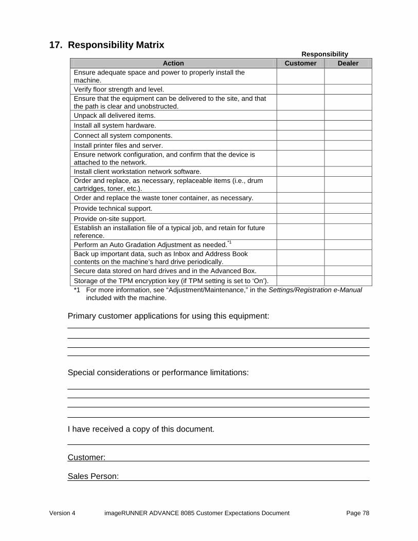
Version 4 imageRUNNER ADVANCE 8085 Customer Expectations Document Page 78
17. Responsibility Matrix Responsibility
Action Customer Dealer Ensure adequate space and power to properly install the machine. Verify floor strength and level. Ensure that the equipment can be delivered to the site, and that the path is clear and unobstructed. Unpack all delivered items. Install all system hardware. Connect all system components. Install printer files and server. Ensure network configuration, and confirm that the device is attached to the network. Install client workstation network software. Order and replace, as necessary, replaceable items (i.e., drum cartridges, toner, etc.). Order and replace the waste toner container, as necessary. Provide technical support. Provide on-site support. Establish an installation file of a typical job, and retain for future reference. Perform an Auto Gradation Adjustment as needed.*1 Back up important data, such as Inbox and Address Book contents on the machine’s hard drive periodically. Secure data stored on hard drives and in the Advanced Box. Storage of the TPM encryption key (if TPM setting is set to ‘On’). *1 For more information, see “Adjustment/Maintenance,” in the Settings/Registration e-Manual
included with the machine. Primary customer applications for using this equipment: Special considerations or performance limitations: I have received a copy of this document. Customer: Sales Person: