Custom Designed Bus Systems - Powell Ind
12
Powered by Safety ® Global Leader in LV and MV Bus Duct Solutions Custom Designed Bus Systems
Transcript of Custom Designed Bus Systems - Powell Ind
Powered by Safety ®
Global Leader in LV and MV Bus Duct Solutions
Custom Designed Bus Systems
2
Powell provides an extensive product
scope, designed and manufactured, to the
exact requirements you need.
table of contents
Global Leader in Bus Duct Technology 6
Unmatched Experience 7
Experience 8
Engineering Studies 8
We Focus on Solutions 8
Service with the Customer in Mind 9
Isolated Phase Bus Design Details 10
Isolated Phase Bus Dimensional Data 11
Isolated Phase Bus Construction Features 12
Isolated Phase Bus Accessories 13
Bus Duct Design Details 14
Non-Segregated Bus Duct Dimensional Data 15
Bus Duct Wall Openings 16
Non-Segregated Bus Duct Components 17
Cable Bus Design Details 18
Cable Bus Design Configurations 19
Application Cross Sections 20
Service and Maintenance of Bus Systems 21
"Can-Do" Attitude
Our "can-do" spirit symbolizes who we are; a world-class producer that embraces complexity through our custom-engineered solutions. We view challenges as opportunities to excel. Our nature is to "make it right" for our customers.
4 5
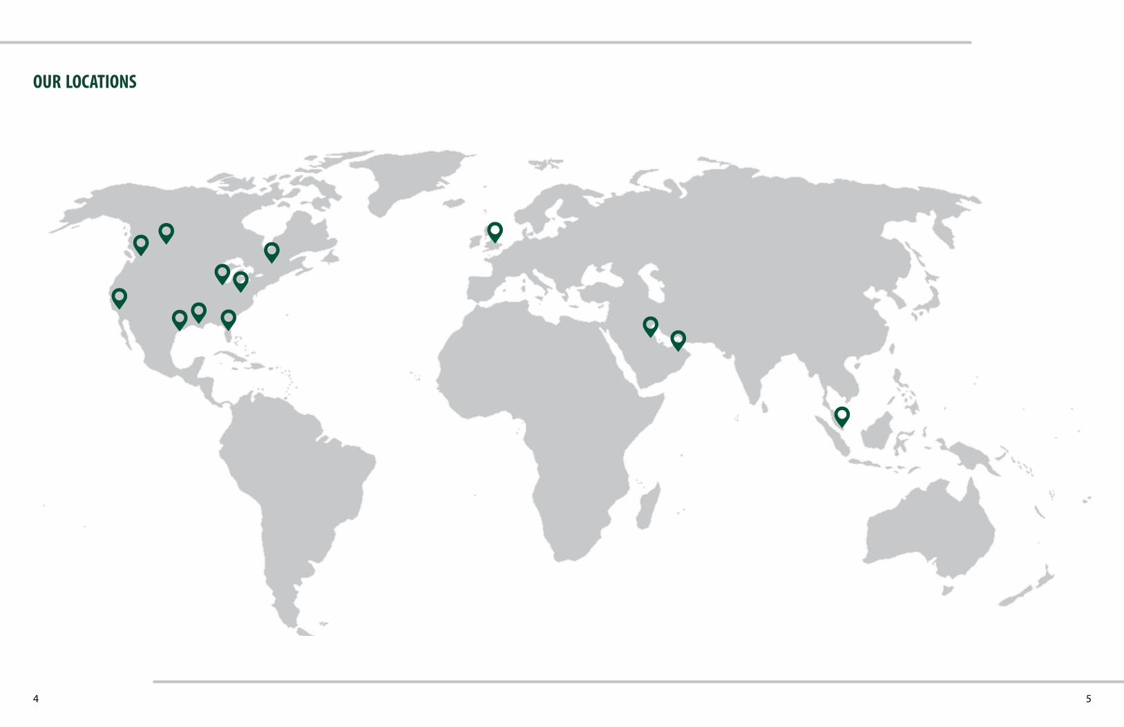
our locations
6 7
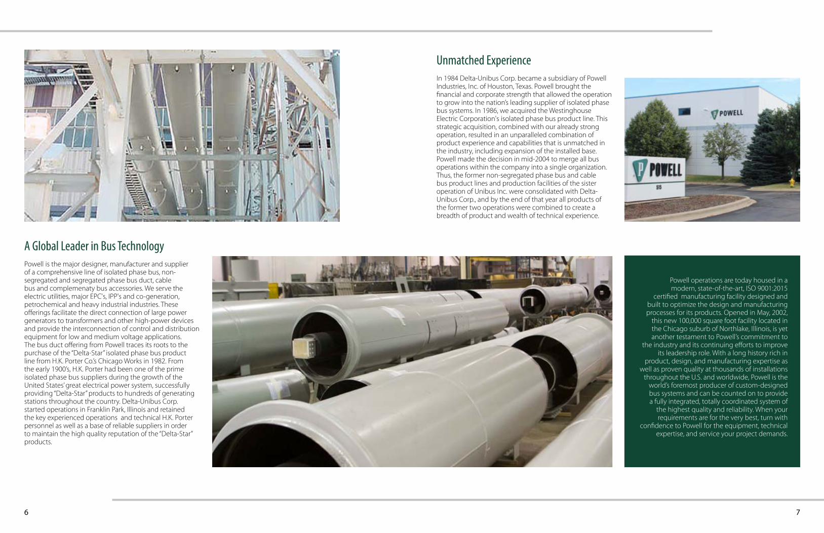
A Global Leader in Bus TechnologyPowell is the major designer, manufacturer and supplier of a comprehensive line of isolated phase bus, non-segregated and segregated phase bus duct, cable bus and complemenaty bus accessories. We serve the electric utilities, major EPC's, IPP's and co-generation, petrochemical and heavy industrial industries. These offerings facilitate the direct connection of large power generators to transformers and other high-power devices and provide the interconnection of control and distribution equipment for low and medium voltage applications.The bus duct offering from Powell traces its roots to the purchase of the “Delta-Star” isolated phase bus product line from H.K. Porter Co.’s Chicago Works in 1982. From the early 1900’s, H.K. Porter had been one of the prime isolated phase bus suppliers during the growth of the United States’ great electrical power system, successfully providing “Delta-Star” products to hundreds of generating stations throughout the country. Delta-Unibus Corp. started operations in Franklin Park, Illinois and retained the key experienced operations and technical H.K. Porter personnel as well as a base of reliable suppliers in order to maintain the high quality reputation of the “Delta-Star” products.
Unmatched ExperienceIn 1984 Delta-Unibus Corp. became a subsidiary of Powell Industries, Inc. of Houston, Texas. Powell brought the financial and corporate strength that allowed the operation to grow into the nation’s leading supplier of isolated phase bus systems. In 1986, we acquired the Westinghouse Electric Corporation's isolated phase bus product line. This strategic acquisition, combined with our already strong operation, resulted in an unparalleled combination of product experience and capabilities that is unmatched in the industry, including expansion of the installed base.Powell made the decision in mid-2004 to merge all bus operations within the company into a single organization. Thus, the former non-segregated phase bus and cable bus product lines and production facilities of the sister operation of Unibus Inc. were consolidated with Delta-Unibus Corp., and by the end of that year all products of the former two operations were combined to create a breadth of product and wealth of technical experience.
Powell operations are today housed in a modern, state-of-the-art, ISO 9001:2015
certified manufacturing facility designed and built to optimize the design and manufacturing processes for its products. Opened in May, 2002,
this new 100,000 square foot facility located in the Chicago suburb of Northlake, Illinois, is yet another testament to Powell’s commitment to
the industry and its continuing efforts to improve its leadership role. With a long history rich in
product, design, and manufacturing expertise as well as proven quality at thousands of installations
throughout the U.S. and worldwide, Powell is the world’s foremost producer of custom-designed bus systems and can be counted on to provide a fully integrated, totally coordinated system of
the highest quality and reliability. When your requirements are for the very best, turn with
confidence to Powell for the equipment, technical expertise, and service your project demands.
8
Thousands of power generating units and industrial applications all over the world depend on the reliability of Powell bus systems. Over 75% of U.S. generating stations have selected designs within the scope and control of Powell since the early 1900’s. With installations in more than forty countries, the claim that Powell is a global leader is validated on a daily basis.
Experience
Our Engineering and Technical Services personnel can assist you in making decisions regarding current equipment at your facility. Whether the consideration is for an upgrade of existing equipment, replacement of aged and outdated equipment, or the need for modifications to allow installation of additional equipment, call on Powell to give the guidance and expert analysis at the outset of a project. Bus duct systems are tested in strict accordance with ANSI/IEEE, NEMA and NEC standards.
Engineering Studies
From the highest rated bus duct system in the industry for a nuclear station in the United States, to the largest combined-cycle plant ever built, to one of the largest domestic hydro stations, Powell has been and continues to be the choice supplier in the power generation industry. Design parameters for our products include conformance to ANSI, BS and DIN standards, giving Powell the ability to completely satisfy the needs of our customers. Powell is available to offer custom solutions based on analysis of a new or existing system. To provide these solutions, Powell can furnish modifications and upgrades to existing ratings as well as designs to meet new application needs. These changes may include replacement or modification of the existing cooling unit. Powell is the industry expert for field engineering services, whether this is for product previously supplied by us or equipment supplied by others. Our products are designed to minimize the time required for field installation, and our track record of quality proves our ability to provide a straightforward, user-friendly product. In the event that assistance is needed in the field, however, our staff has the background and experience to provide the Field Service that you may need as the situation arises.
We Focus on Solutions
9
Service with the Customer in Mind
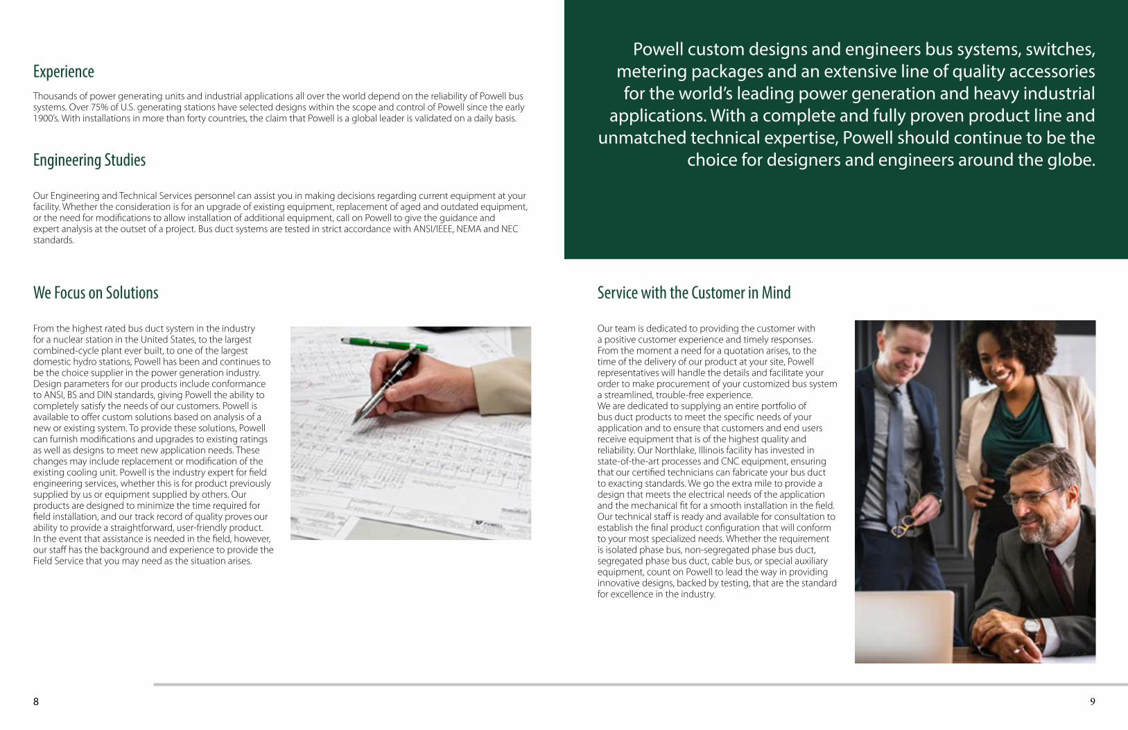
Our team is dedicated to providing the customer with a positive customer experience and timely responses. From the moment a need for a quotation arises, to the time of the delivery of our product at your site, Powell representatives will handle the details and facilitate your order to make procurement of your customized bus system a streamlined, trouble-free experience.We are dedicated to supplying an entire portfolio of bus duct products to meet the specific needs of your application and to ensure that customers and end users receive equipment that is of the highest quality and reliability. Our Northlake, Illinois facility has invested in state-of-the-art processes and CNC equipment, ensuring that our certified technicians can fabricate your bus duct to exacting standards. We go the extra mile to provide a design that meets the electrical needs of the application and the mechanical fit for a smooth installation in the field. Our technical staff is ready and available for consultation to establish the final product configuration that will conform to your most specialized needs. Whether the requirement is isolated phase bus, non-segregated phase bus duct, segregated phase bus duct, cable bus, or special auxiliary equipment, count on Powell to lead the way in providing innovative designs, backed by testing, that are the standard for excellence in the industry.
Powell custom designs and engineers bus systems, switches, metering packages and an extensive line of quality accessories for the world’s leading power generation and heavy industrial
applications. With a complete and fully proven product line and unmatched technical expertise, Powell should continue to be the
choice for designers and engineers around the globe.
10 11
Isolated Phase Bus Design DetailsPowell serves the electric utility and the cogeneration industries with a complete range of products, systems and services for direct connection of large power generators to transformers and other large apparatus. The inherent design features built into Powell products provide a high degree of reliability and maximum protection for the generator and for other connected equipment providing innovative designs, backed by testing, that are the standard for excellence in the industry.
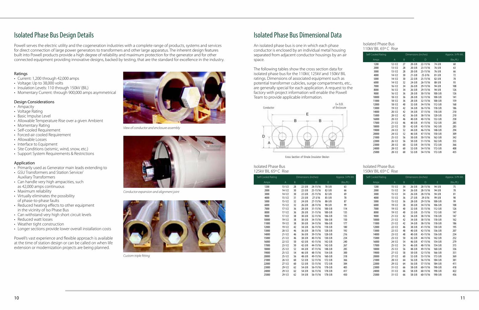
Isolated Phase Bus Dimensional DataAn isolated phase bus is one in which each phase conductor is enclosed by an individual metal housing separated from adjacent conductor housings by an air space.
The following tables show the cross section data for isolated phase bus for the 110kV, 125kV and 150kV BIL ratings. Dimensions of associated equipment such as potential transformer cubicles, surge compartments, etc., are generally special for each application. A request to the factory with project information will enable the Powell Team to provide applicable information.
Ratings• Current: 1,200 through 42,000 amps• Voltage: Up to 38,000 volts• Insulation Levels: 110 through 150kV (BIL)• Momentary Current: through 900,000 amps asymmetrical
Design Considerations• Ampacity• Voltage Rating• Basic Impulse Level• Allowable Temperature Rise over a given Ambient• Momentary Rating• Self-cooled Requirement• Forced-air cooled Requirement• Allowable Losses• Interface to Equipment• Site Conditions (seismic, wind, snow, etc.)• Support System Requirements & Restrictions
Application• Primarily used as Generator main leads extending to• GSU Transformers and Station Service/
Auxiliary Transformers• Can handle very high ampacities, such
as 42,000 amps continuous• Maximum reliability• Virtually eliminates the possibility
of phase-to-phase faults• Reduced heating effects to other equipment
in the vicinity of Iso Phase Bus• Can withstand very high short circuit levels• Reduced watt losses• Weather tight construction• Longer sections provide lower overall installation costs
Powell’s vast experience and flexible approach is available at the time of station design or can be called on when life extension or modernization projects are being planned.
View of conductor and enclosure assembly
Conductor expansion and alignment joint
Custom triple fitting
Self Cooled Rating Dimensions (inches) Approx. 3-Ph Wt.
Amps A B C D E (lbs./ft.)
1200 12-1/2 27 20-3/8 22-11/16 74-3/8 602000 13-1/2 28 20-3/8 23-11/16 76-3/8 633000 13-1/2 28 20-3/8 23-11/16 76-3/8 664000 14-1/2 30 21-3/8 25-3/16 81-3/8 725000 14-1/2 30 22-3/8 25-11/16 82-3/8 786000 14-1/2 32 24-3/8 26-11/16 88-3/8 937000 16-1/2 34 26-3/8 29-11/16 94-3/8 1088000 16-1/2 34 26-3/8 29-11/16 94-3/8 1269000 16-1/2 36 28-3/8 30-11/16 100-3/8 126
10000 18-1/2 36 28-3/8 32-11/16 100-3/8 14111000 18-1/2 36 28-3/8 32-11/16 100-3/8 15912000 18-1/2 40 32-3/8 34-11/16 112-3/8 16813000 19-1/2 42 34-3/8 36-11/16 118-3/8 18614000 20-1/2 42 34-3/8 37-11/16 118-3/8 21015000 20-1/2 42 36-3/8 38-11/16 120-3/8 21016000 20-1/2 46 40-3/8 40-11/16 132-3/8 25817000 21-1/2 46 40-3/8 41-11/16 132-3/8 28518000 22-1/2 50 42-3/8 43-11/16 142-3/8 28519000 24-1/2 52 44-3/8 46-11/16 148-3/8 29420000 24-1/2 52 46-3/8 47-11/16 150-3/8 30921000 25-1/2 56 50-3/8 50-11/16 162-3/8 34222000 26-1/2 56 50-3/8 51-11/16 162-3/8 35523000 28-1/2 60 52-3/8 54-11/16 172-3/8 36624000 28-1/2 60 52-3/8 54-11/16 172-3/8 40825000 28-1/2 60 52-3/8 54-11/16 172-3/8 435
Self Cooled Rating Dimensions (inches) Approx. 3-Ph Wt.
Amps A B C D E (lbs./ft.)
1200 13-1/2 28 22-3/8 24-11/16 78-3/8 632000 14-1/2 30 22-3/8 25-11/16 82-3/8 663000 14-1/2 30 22-3/8 25-11/16 82-3/8 694000 15-1/2 31 23-3/8 27-3/16 85-3/8 785000 15-1/2 32 24-3/8 27-11/16 88-3/8 876000 15-1/2 32 26-3/8 28-11/16 90-3/8 997000 17-1/2 36 28-3/8 31-11/16 100-3/8 1148000 17-1/2 36 28-3/8 31-11/16 100-3/8 1359000 17-1/2 38 30-3/8 32-11/16 106-3/8 135
10000 19-1/2 38 30-3/8 34-11/16 106-3/8 15011000 19-1/2 38 30-3/8 34-11/16 106-3/8 17712000 19-1/2 42 34-3/8 36-11/16 118-3/8 18013000 20-1/2 46 36-3/8 38-11/16 128-3/8 19214000 21-1/2 46 36-3/8 39-11/16 128-3/8 21615000 21-1/2 46 38-3/8 40-11/16 130-3/8 23416000 22-1/2 50 42-3/8 43-11/16 142-3/8 24017000 23-1/2 50 42-3/8 44-11/16 142-3/8 26718000 25-1/2 52 44-3/8 47-11/16 148-3/8 28519000 25-1/2 54 46-3/8 48-11/16 154-3/8 30020000 25-1/2 56 48-3/8 49-11/16 160-3/8 31821000 26-1/2 60 52-3/8 52-11/16 172-3/8 36622000 27-1/2 60 52-3/8 53-11/16 172-3/8 38423000 29-1/2 62 54-3/8 56-11/16 178-3/8 40524000 29-1/2 62 54-3/8 56-11/16 178-3/8 41725000 29-1/2 62 54-3/8 56-11/16 178-3/8 450
Self Cooled Rating Dimensions (inches) Approx. 3-Ph Wt.
Amps A B C D E (lbs./ft.)
1200 15-1/2 34 26-3/8 28-11/16 94-3/8 752000 15-1/2 34 26-3/8 28-11/16 94-3/8 783000 15-1/2 34 26-3/8 28-11/16 94-3/8 814000 15-1/2 36 27-3/8 29-3/16 99-3/8 905000 15-1/2 36 28-3/8 29-11/16 100-3/8 996000 19-1/2 38 30-3/8 34-11/16 106-3/8 1087000 19-1/2 40 32-3/8 35-11/16 112-3/8 1268000 19-1/2 40 32-3/8 35-11/16 112-3/8 1479000 21-1/2 42 34-3/8 38-11/16 118-3/8 147
10000 21-1/2 42 34-3/8 38-11/16 118-3/8 16211000 21-1/2 42 34-3/8 38-11/16 118-3/8 18612000 22-1/2 46 38-3/8 41-11/16 130-3/8 19513000 22-1/2 48 40-3/8 42-11/16 136-3/8 20714000 23-1/2 48 40-3/8 43-11/16 136-3/8 23415000 23-1/2 50 42-3/8 44-11/16 142-3/8 25216000 24-1/2 54 46-3/8 47-11/16 154-3/8 27917000 25-1/2 54 46-3/8 48-11/16 154-3/8 31518000 25-1/2 56 48-3/8 49-11/16 160-3/8 33619000 27-1/2 58 50-3/8 52-11/16 166-3/8 35120000 27-1/2 60 52-3/8 53-11/16 172-3/8 36921000 28-1/2 64 56-3/8 56-11/16 184-3/8 38122000 29-1/2 64 56-3/8 57-11/16 184-3/8 41123000 31-1/2 66 58-3/8 60-11/16 190-3/8 41824000 31-1/2 66 58-3/8 60-11/16 190-3/8 42225000 31-1/2 66 58-3/8 60-11/16 190-3/8 456
Isolated Phase Bus110kV BIL 65º C Rise
Isolated Phase Bus150kV BIL 65º C Rise
Isolated Phase Bus125kV BIL 65º C Rise
12 13
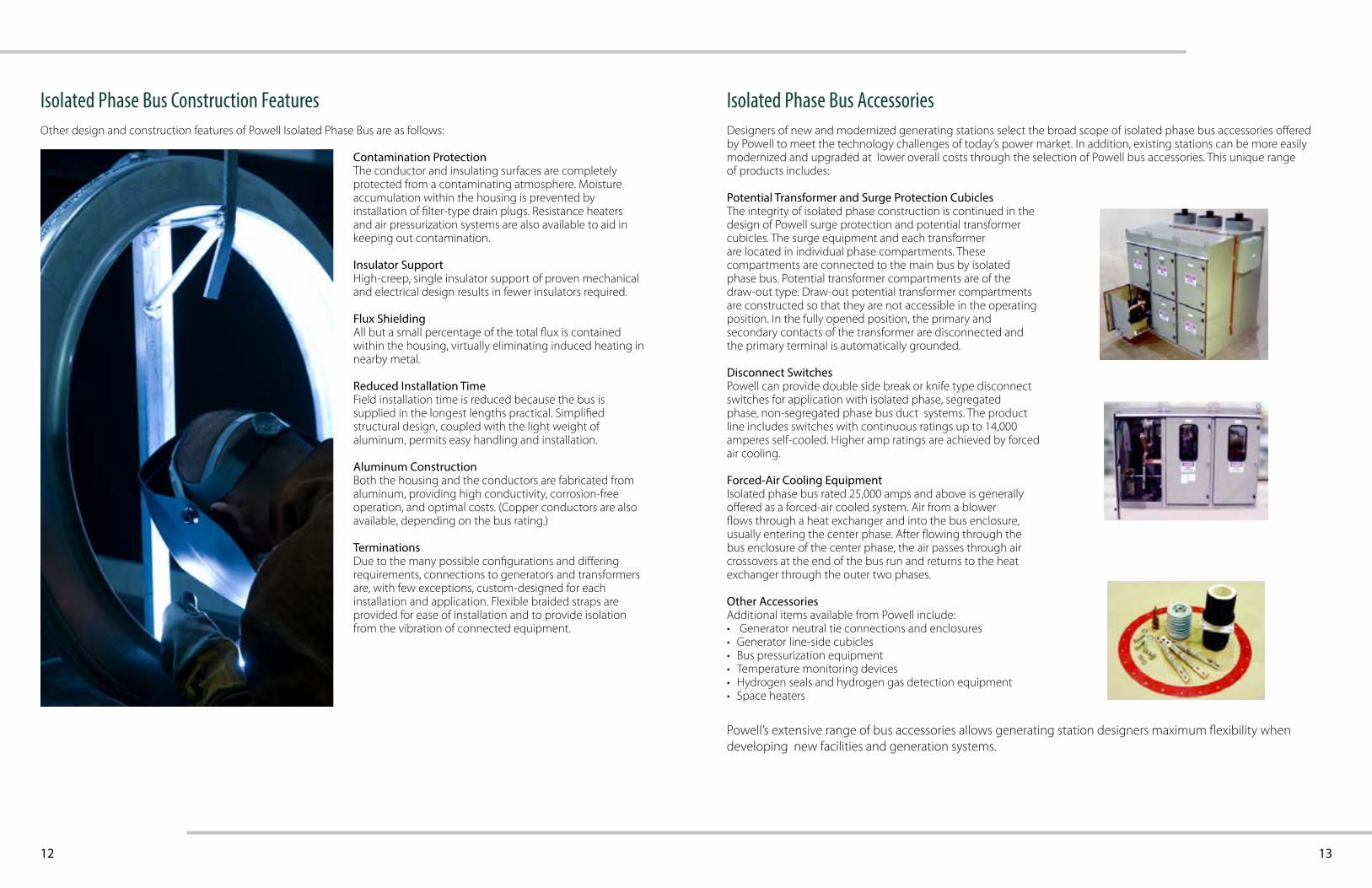
Potential Transformer and Surge Protection CubiclesThe integrity of isolated phase construction is continued in the design of Powell surge protection and potential transformer cubicles. The surge equipment and each transformer are located in individual phase compartments. These compartments are connected to the main bus by isolated phase bus. Potential transformer compartments are of the draw-out type. Draw-out potential transformer compartments are constructed so that they are not accessible in the operating position. In the fully opened position, the primary and secondary contacts of the transformer are disconnected and the primary terminal is automatically grounded.
Disconnect SwitchesPowell can provide double side break or knife type disconnect switches for application with isolated phase, segregated phase, non-segregated phase bus duct systems. The product line includes switches with continuous ratings up to 14,000 amperes self-cooled. Higher amp ratings are achieved by forced air cooling.
Forced-Air Cooling EquipmentIsolated phase bus rated 25,000 amps and above is generally offered as a forced-air cooled system. Air from a blower flows through a heat exchanger and into the bus enclosure, usually entering the center phase. After flowing through the bus enclosure of the center phase, the air passes through air crossovers at the end of the bus run and returns to the heat exchanger through the outer two phases.
Other AccessoriesAdditional items available from Powell include:• Generator neutral tie connections and enclosures• Generator line-side cubicles• Bus pressurization equipment • Temperature monitoring devices• Hydrogen seals and hydrogen gas detection equipment• Space heaters
Isolated Phase Bus Construction Features
Contamination ProtectionThe conductor and insulating surfaces are completely protected from a contaminating atmosphere. Moisture accumulation within the housing is prevented by installation of filter-type drain plugs. Resistance heaters and air pressurization systems are also available to aid in keeping out contamination.
Insulator SupportHigh-creep, single insulator support of proven mechanical and electrical design results in fewer insulators required.
Flux ShieldingAll but a small percentage of the total flux is contained within the housing, virtually eliminating induced heating in nearby metal.
Reduced Installation TimeField installation time is reduced because the bus is supplied in the longest lengths practical. Simplified structural design, coupled with the light weight of aluminum, permits easy handling and installation.
Aluminum ConstructionBoth the housing and the conductors are fabricated from aluminum, providing high conductivity, corrosion-free operation, and optimal costs. (Copper conductors are also available, depending on the bus rating.)
TerminationsDue to the many possible configurations and differing requirements, connections to generators and transformers are, with few exceptions, custom-designed for each installation and application. Flexible braided straps are provided for ease of installation and to provide isolation from the vibration of connected equipment.
Isolated Phase Bus AccessoriesOther design and construction features of Powell Isolated Phase Bus are as follows: Designers of new and modernized generating stations select the broad scope of isolated phase bus accessories offered
by Powell to meet the technology challenges of today’s power market. In addition, existing stations can be more easily modernized and upgraded at lower overall costs through the selection of Powell bus accessories. This unique rangeof products includes:
Powell’s extensive range of bus accessories allows generating station designers maximum flexibility when developing new facilities and generation systems.
14 15
Bus Duct Design DetailsTechnical data for Powell standard non-segregated and segregated bus duct configurations is presented for design and layout purposes. Ratings have been tested in accordance with industry standards for a high level of reliability and to meet specification requirements. For further information or for ratings greater than 15kV or 5000 Amps, please contact our factory sales representatives.
EnclosuresAluminum enclosures are standard for Powell. Mild steel and stainless steel enclosures are available to meet a variety of environmental requirements. Outdoor housings are weatherproof with gasketed and peaked top covers, screened breathers, and heaters for control of condensation. Typical indoor housings are totally enclosed, although ventilated bus is available with open top and bottom covers. The standard finish color is ANSI 61 gray, but special colors can be provided to match connected equipment. The enclosure usually serves as the ground conductor for the system, with ground bars, internal or external to the enclosure, available as an option.
ConductorsCopper conductors are standard. Silver-plated contact surfaces are provided at all joints and terminations. For all ratings, aluminum conductors can be supplied. Tin plated joints are standard when aluminum conductors are used.
Conductor InsulationBars on 5kV and higher ratings are insulated with electrostatically applied powder epoxy to provide an insulation quality unmatched in the industry. Bus bars are normally uninsulated for 600-volt service. Specially designed insulating boots aid in the installation of Powell equipment.
Conductor SupportsMolded fiberglass reinforced polyester blocks are utilized in standard ratings to provide the insulator support for conductors. Support spacing is determined based on short-circuit requirements and is established to withstand the electromagnetic forces during fault conditions. For special applications, molded epoxy blocks, wet-process porcelain or epoxy post insulators can be provided.
4-Pole Bus and Other DesignsSystems including half-neutrals, full neutrals, DC designs and other configurations are available from Powell. Information for enclosure sizes and ratings shown are standard Powell designs for a typical ambient temperature of 40oC. The housing is designed for a maximumtemperature rise of 40oC and the conductors are designed for a maximum rise of 65oC over a 40oC ambient. Additional custom ambient designs are available.
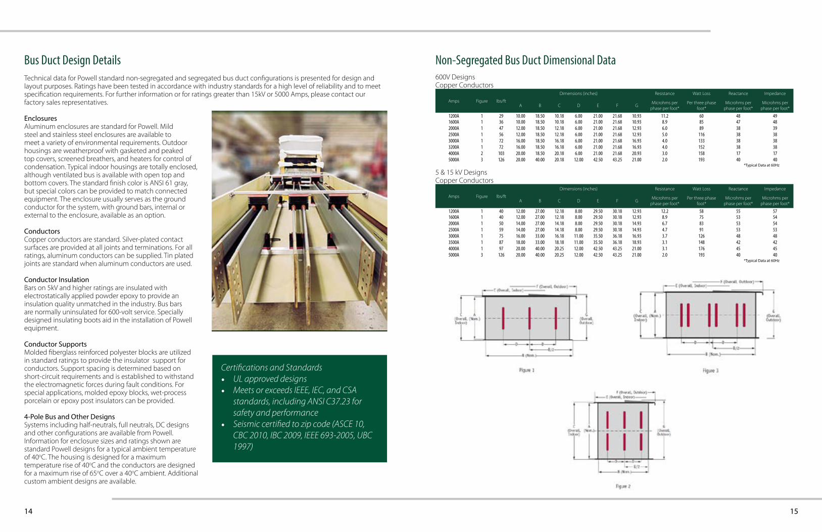
Non-Segregated Bus Duct Dimensional Data
Amps Figure lbs/ft
Dimensions (inches) Resistance Watt Loss Reactance Impedance
A B C D E F GMicrohms per
phase per foot*Per three phase
foot*Microhms per
phase per foot*Microhms per
phase per foot*
1200A 1 29 10.00 18.50 10.18 6.00 21.00 21.68 10.93 11.2 60 48 491600A 1 36 10.00 18.50 10.18 6.00 21.00 21.68 10.93 8.9 85 47 482000A 1 47 12.00 18.50 12.18 6.00 21.00 21.68 12.93 6.0 89 38 392500A 1 56 12.00 18.50 12.18 6.00 21.00 21.68 12.93 5.0 116 38 383000A 1 72 16.00 18.50 16.18 6.00 21.00 21.68 16.93 4.0 133 38 383200A 1 72 16.00 18.50 16.18 6.00 21.00 21.68 16.93 4.0 152 38 384000A 2 103 20.00 18.50 20.18 6.00 21.00 21.68 20.93 3.0 158 17 175000A 3 126 20.00 40.00 20.18 12.00 42.50 43.25 21.00 2.0 193 40 40
600V Designs Copper Conductors
Amps Figure lbs/ft
Dimensions (inches) Resistance Watt Loss Reactance Impedance
A B C D E F GMicrohms per
phase per foot*Per three phase
foot*Microhms per
phase per foot*Microhms per
phase per foot*
1200A 1 40 12.00 27.00 12.18 8.00 29.50 30.18 12.93 12.2 58 55 571600A 1 40 12.00 27.00 12.18 8.00 29.50 30.18 12.93 8.9 75 53 542000A 1 50 14.00 27.00 14.18 8.00 29.50 30.18 14.93 6.7 83 53 542500A 1 59 14.00 27.00 14.18 8.00 29.50 30.18 14.93 4.7 91 53 533000A 1 75 16.00 33.00 16.18 11.00 35.50 36.18 16.93 3.7 126 48 483500A 1 87 18.00 33.00 18.18 11.00 35.50 36.18 18.93 3.1 148 42 424000A 1 97 20.00 40.00 20.25 12.00 42.50 43.25 21.00 3.1 176 45 455000A 3 126 20.00 40.00 20.25 12.00 42.50 43.25 21.00 2.0 193 40 40
5 & 15 kV Designs Copper Conductors
*Typical Data at 60Hz
*Typical Data at 60Hz
Certifications and Standards• UL approved designs• Meets or exceeds IEEE, IEC, and CSA
standards, including ANSI C37.23 for safety and performance
• Seismic certified to zip code (ASCE 10, CBC 2010, IBC 2009, IEEE 693-2005, UBC 1997)
16 17
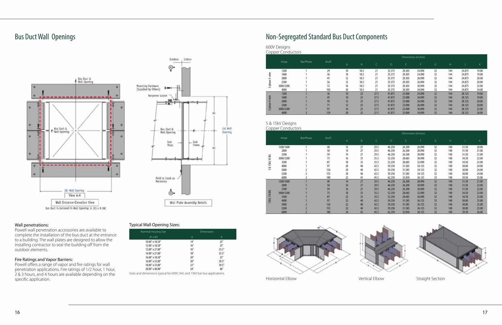
Bus Duct Wall Openings
Wall penetrations:Powell wall penetration accessories are available to complete the installation of the bus duct at the entrance to a building. The wall plates are designed to allow the installing contractor to seal the building off from the outdoor elements.
Fire Ratings and Vapor Barriers:Powell offers a range of vapor and fire ratings for wall penetration applications. Fire ratings of 1/2 hour, 1 hour, 2 & 3 hours, and 4 hours are available depending on the specific application.
Non-Segregated Standard Bus Duct Components
Amps Bar/Phase lbs/ft
Dimensions (inches)
A B C D E F G H J K
3-ph
ase 3
- wire
1200 1 29 10 18.5 21 35.375 20.305 24.090 32 144 24.875 19.001600 1 36 10 18.5 21 35.375 20.305 24.090 32 144 24.875 19.002000 1 47 12 18.5 21 35.375 20.305 26.090 32 144 24.875 20.002500 1 56 12 18.5 21 35.375 20.305 26.090 32 144 24.875 20.00
3000/3200 1 72 16 18.5 21 35.375 20.305 30.090 32 144 24.875 22.004000 2 103 20 18.5 21 35.375 20.305 34.090 32 144 24.875 24.00
3-ph
ase 4
-wire
1200 1 36 10 25 27.5 41.875 23.000 24.090 32 144 28.125 19.001600 1 45 10 25 27.5 41.875 23.000 24.090 32 144 28.125 19.002000 1 59 12 25 27.5 41.875 23.000 26.090 32 144 28.125 20.002500 1 71 12 25 27.5 41.875 23.000 26.090 32 144 28.125 20.00
3000/3200 1 91 16 25 27.5 41.875 23.000 30.090 32 144 28.125 22.004000 2 129 20 25 27.5 41.875 23.000 34.090 32 144 28.125 24.00
600V Designs Copper Conductors
Nominal Housing Size Dimensions
(H x W) A B
10.00" x 18.50" 14" 25"12.00" x 18.50" 16" 25"12.00" x 27.00" 16" 33.5"14.00" x 27.00" 18" 33.5"16.00" x 18.50" 20" 25"16.00" x 33.00" 20" 39.5"18.00" x 33.00" 22" 39.5"20.00" x 40.00" 24" 46"
Typical Wall Opening Sizes:
Sizes and dimensions typical for 600V, 5kV, and 15kV bar bus applications.
Amps Bar/Phase lbs/ft
Dimensions (inches)
A B C D E F G H J K
5 & 15
kV, 9
5 BIL
1200/1600 1 40 12 27 29.5 46.250 26.200 26.090 32 140 31.50 20.002000 1 50 14 27 29.5 46.250 26.200 28.090 32 140 31.50 21.002500 1 59 14 27 29.5 46.250 26.200 28.090 32 140 31.50 21.00
3000/3200 1 75 16 33 35.5 52.250 28.685 30.090 32 140 34.50 22.003500 1 87 18 33 35.5 52.250 28.685 32.090 32 140 34.50 23.004000 1 97 20 40 42.5 59.250 31.585 34.125 32 140 38.00 24.005000 2 126 20 40 42.5 59.250 31.585 34.125 32 140 38.00 24.005200 2 155 20 40 42.5 59.250 31.585 34.125 32 140 38.00 24.006000 2 180 22 43 45.5 62.250 32.830 36.125 33 140 39.50 25.00
15kV
, 110
BIL
1200/1600 1 40 14 27 29.5 46.250 26.200 28.090 32 140 31.50 21.002000 1 50 16 27 29.5 46.250 26.200 30.090 32 140 31.50 22.002500 1 59 16 27 29.5 46.250 26.200 30.090 32 140 31.50 22.00
3000/3200 1 75 18 33 35.5 52.250 28.685 32.090 32 140 34.50 23.003500 1 87 22 33 35.5 52.250 28.685 36.090 32 140 34.50 25.004000 1 97 22 40 42.5 59.250 31.585 36.125 32 140 38.00 25.005000 2 126 22 40 42.5 59.250 31.585 36.125 32 140 38.00 25.005200 2 155 22 40 42.5 59.250 31.585 36.125 32 140 38.00 25.006000 2 180 24 43 45.5 62.250 32.830 38.125 32 140 39.50 26.00
5 & 15kV Designs Copper Conductors
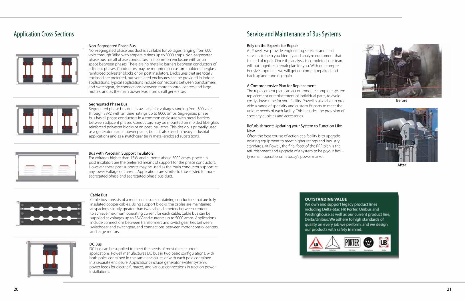
Vertical Elbow
Horizontal Elbow Vertical Elbow Straight Section
18 19
Cable Bus Design Details Cable Bus Design Configurations
Maximum Current Rating
Cable OptionsTotal # of
Cables
Rows x
Cables
Nom Housing
Dim (in)
Min Cable
OD (in)
Max Cable
OD (in)
Weight per foot
(lbs)
Nom Housing
Dim (in)
Min Cable
OD (in)
Max Cable
OD (in)
Weight per foot
(lbs)
Nom Housing
Dim (in)
Min Cable
OD (in)
Max Cable
OD (in)
Weight per foot
(lbs)
# per phase
Type 600V 5kV 15kV
40o C A
mbie
nt D
esign
800A 1 750MCM 3 1 x 3 6 x 15 1.13 1.37 17.56 x 15 1.44 1.56 18.5
6 x 18.5 1.59 1.89 22.06 x 18.5 1.57 1.61 21.0
1200A 2 500MCM 6 2 x 3 8 x 15 0.92 1.16 22.0 8 x 15 1.25 1.41 24.0 8 x 15 1.41 1.56 25.510 x 18.5 1.57 1.63 28.5
1600A 2 750MCM 6 2 x 3 8 x 15 1.13 1.37 37.0 8 x 15 1.44 1.56 29.0 10 x 18.5 1.59 1.89 35.010 x 18.5 1.57 1.61 32.5
2000A 3 750MCM 9 2 x 5 8 x 21 1.13 1.37 37.0 8 x 21 1.44 1.56 40.5 10 x 25 1.59 1.89 47.510 x 25 1.57 1.61 44.0
2500A 4 500MCM 12 2 x 6 8 x 25 .92 1.16 36.5 8 x 25 1.25 1.41 41.0 8 x 25 1.41 1.56 44.010 x 29 1.57 1.63 47.5
3000A 4 750MCM 12 2 x 6 8 x 25 1.13 1.37 47.0 8 x 25 1.44 1.56 51.5 10 x 29 1.59 1.89 60.010 x 29 1.57 1.61 55.0
3500A 4 1000MCM 12 2 x 6 8 x 25 1.28 1.52 56.0 10 x 29 1.58 1.80 65.0 10 x 29 1.73 2.04 71.0
4000A 6 750MCM 18 3 x 6 12 x 25 1.13 1.37 66.0 12 x 25 1.44 1.56 72.5 14 x 29 1.59 1.89 85.014 x 29 1.57 1.61 77.0
5000A 6 1000MCM 18 3 x 6 12 x 25 1.28 1.52 80.0 14 x 29 1.58 1.80 92.5 14 x 29 1.73 2.04 102.0
Copper cable for 600V and 5kV can be shielded or non-shielded. Copper cable for 15kV ratings is provided with shielded construction.
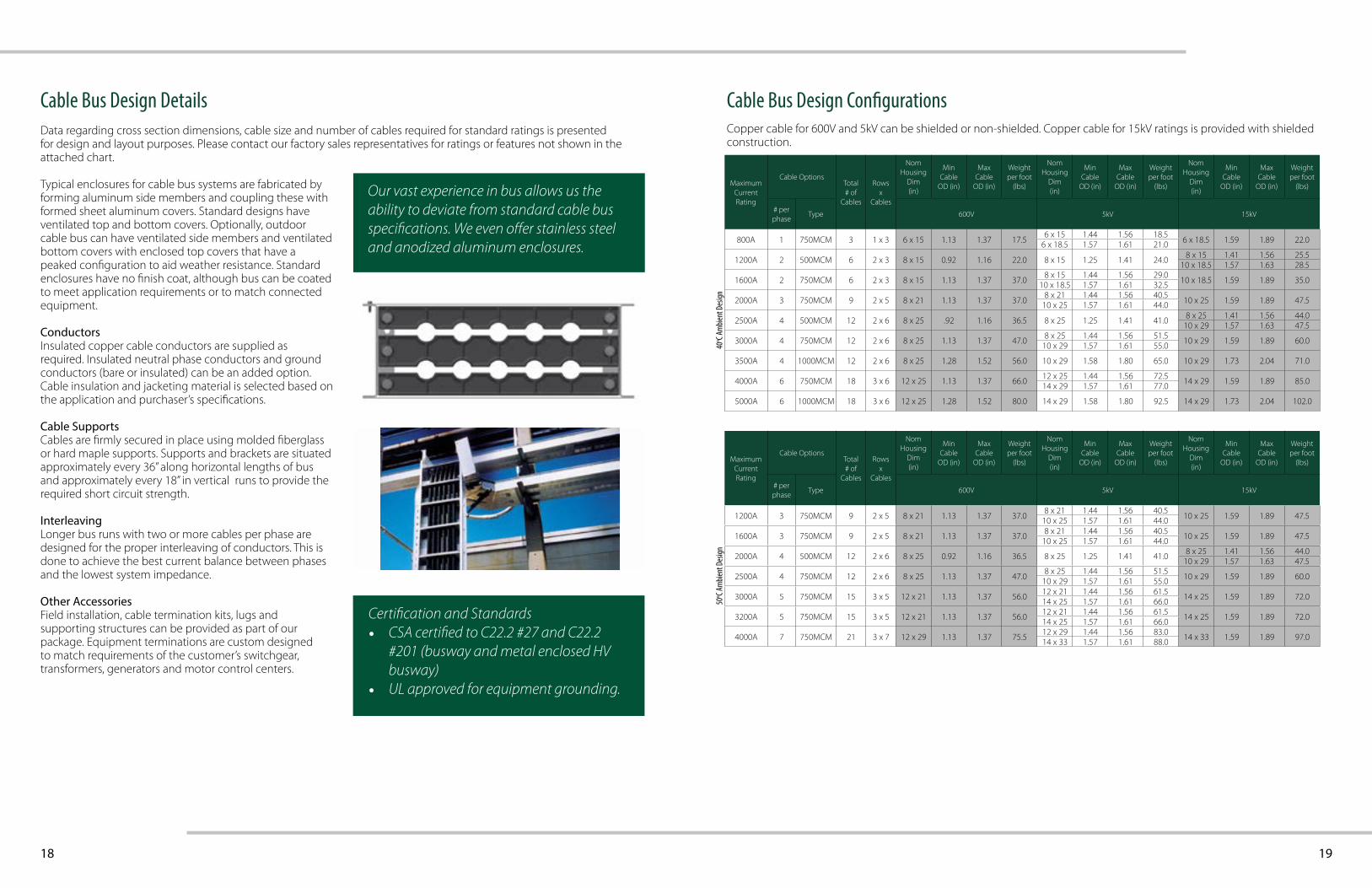
Typical enclosures for cable bus systems are fabricated by forming aluminum side members and coupling these with formed sheet aluminum covers. Standard designs have ventilated top and bottom covers. Optionally, outdoor cable bus can have ventilated side members and ventilated bottom covers with enclosed top covers that have a peaked configuration to aid weather resistance. Standard enclosures have no finish coat, although bus can be coated to meet application requirements or to match connected equipment.
ConductorsInsulated copper cable conductors are supplied as required. Insulated neutral phase conductors and ground conductors (bare or insulated) can be an added option. Cable insulation and jacketing material is selected based on the application and purchaser’s specifications.
Cable SupportsCables are firmly secured in place using molded fiberglass or hard maple supports. Supports and brackets are situated approximately every 36” along horizontal lengths of bus and approximately every 18” in vertical runs to provide the required short circuit strength.
InterleavingLonger bus runs with two or more cables per phase are designed for the proper interleaving of conductors. This is done to achieve the best current balance between phases and the lowest system impedance.
Other AccessoriesField installation, cable termination kits, lugs and supporting structures can be provided as part of our package. Equipment terminations are custom designed to match requirements of the customer’s switchgear, transformers, generators and motor control centers.
Our vast experience in bus allows us the ability to deviate from standard cable bus specifications. We even offer stainless steel and anodized aluminum enclosures.
Data regarding cross section dimensions, cable size and number of cables required for standard ratings is presented for design and layout purposes. Please contact our factory sales representatives for ratings or features not shown in the attached chart.
Maximum Current Rating
Cable OptionsTotal # of
Cables
Rows x
Cables
Nom Housing
Dim (in)
Min Cable
OD (in)
Max Cable
OD (in)
Weight per foot
(lbs)
Nom Housing
Dim (in)
Min Cable
OD (in)
Max Cable
OD (in)
Weight per foot
(lbs)
Nom Housing
Dim (in)
Min Cable
OD (in)
Max Cable
OD (in)
Weight per foot
(lbs)
# per phase
Type 600V 5kV 15kV
50o C A
mbie
nt D
esign
1200A 3 750MCM 9 2 x 5 8 x 21 1.13 1.37 37.08 x 21 1.44 1.56 40.5
10 x 25 1.59 1.89 47.510 x 25 1.57 1.61 44.0
1600A 3 750MCM 9 2 x 5 8 x 21 1.13 1.37 37.0 8 x 21 1.44 1.56 40.5 10 x 25 1.59 1.89 47.510 x 25 1.57 1.61 44.0
2000A 4 500MCM 12 2 x 6 8 x 25 0.92 1.16 36.5 8 x 25 1.25 1.41 41.0 8 x 25 1.41 1.56 44.010 x 29 1.57 1.63 47.5
2500A 4 750MCM 12 2 x 6 8 x 25 1.13 1.37 47.0 8 x 25 1.44 1.56 51.5 10 x 29 1.59 1.89 60.010 x 29 1.57 1.61 55.0
3000A 5 750MCM 15 3 x 5 12 x 21 1.13 1.37 56.0 12 x 21 1.44 1.56 61.5 14 x 25 1.59 1.89 72.014 x 25 1.57 1.61 66.0
3200A 5 750MCM 15 3 x 5 12 x 21 1.13 1.37 56.0 12 x 21 1.44 1.56 61.5 14 x 25 1.59 1.89 72.014 x 25 1.57 1.61 66.0
4000A 7 750MCM 21 3 x 7 12 x 29 1.13 1.37 75.5 12 x 29 1.44 1.56 83.0 14 x 33 1.59 1.89 97.014 x 33 1.57 1.61 88.0
Certification and Standards• CSA certified to C22.2 #27 and C22.2
#201 (busway and metal enclosed HV busway)
• UL approved for equipment grounding.
20 21
Application Cross Sections
Bus with Porcelain Support InsulatorsFor voltages higher than 15kV and currents above 5000 amps, porcelain post insulators are the preferred means of support for the phase conductors. However, these post supports may be used as the main conductor support at any lower voltage or current. Applications are similar to those listed for non-segregated phase and segregated phase bus duct.
Segregated Phase BusSegregated phase bus duct is available for voltages ranging from 600 volts through 38kV, with ampere ratings up to 8000 amps. Segregated phase bus has all phase conductors in a common enclosure with metal barriers between adjacent phases. Conductors may be mounted on molded fiberglass reinforced polyester blocks or on post insulators. This design is primarily used as a generator lead in power plants, but it is also used in heavy industrial applications and as a switchgear tie in metal-enclosed substations.
Non-Segregated Phase BusNon-segregated phase bus duct is available for voltages ranging from 600 volts through 38kV, with ampere ratings up to 8000 amps. Non-segregated phase bus has all phase conductors in a common enclosure with an air space between phases. There are no metallic barriers between conductors of adjacent phases. Conductors may be mounted on custom molded fiberglass reinforced polyester blocks or on post insulators. Enclosures that are totally enclosed are preferred, but ventilated enclosures can be provided in indoor applications. Typical applications include connections between transformers and switchgear, tie connections between motor control centers and large motors, and as the main power lead from small generators.
DC BusDC bus can be supplied to meet the needs of most direct current applications. Powell manufactures DC bus in two basic configurations: with both poles contained in the same enclosure, or with each pole contained in a separate enclosure. Applications include generator exciter systems, power feeds for electric furnaces, and various connections in traction power installations.
Cable BusCable bus consists of a metal enclosure containing conductors that are fully insulated copper cables. Using support blocks, the cables are maintained at spacings slightly greater than two cable diameters between centers to achieve maximum operating current for each cable. Cable bus can be supplied at voltages up to 38kV and currents up to 5000 amps. Applications include connections between transformers and switchgear, ties between switchgear and switchgear, and connections between motor control centers and large motors.
Rely on the Experts for RepairAt Powell, we provide engineering services and field services to help you identify and analyze equipment that is need of repair. Once the analysis is completed, our team will put together a repair plan for you. With our compre-hensive approach, we will get equipment repaired and back up and running again.
A Comprehensive Plan for ReplacementThe replacement plan can accommodate complete system replacement or replacement of individual parts, to avoid costly down time for your facility. Powell is also able to pro-vide a range of specialty and custom-fit parts to meet the unique needs of each facility. This includes the provision of specialty cubicles and accessories.
Refurbishment: Updating your System to Function Like NewOften the best course of action at a facility is to upgrade existing equipment to meet higher ratings and industry standards. At Powell, the final facet of the RRR plan is the refurbishment and upgrade of a system to help your facili-ty remain operational in today’s power market.
Service and Maintenance of Bus Systems
Before
After
Asia Pacific
contact us
©2018 Powell Industries, Inc. All Rights Reserved.Publication No. 05001 Rev. 1
Powered by Safety
®
+65 6737 2959
Middle East
North & South America
UK & Europe
1 800 480 7273
+44 1274 734221
+971 4 817 0215
Connect with us!


![[Baden Powell] Baden Powell. Songbook, Vol. 3 (Gui(Bookos.org)](https://static.fdocuments.in/doc/165x107/577cd5c61a28ab9e789b9a94/baden-powell-baden-powell-songbook-vol-3-guibookosorg.jpg)