CUSTODY TRANSFER METERING3 Figure 3-Pressure loss across the DP meter Turbine meters were approved...
14
flotek.g 2017- “Innovative Solutions in Flow Measurement and Control - Oil, Water and Gas” August 28-30, 2017, FCRI, Palakkad, Kerala, India 1 CUSTODY TRANSFER METERING Pranali Salunke Mahanagar Gas Ltd. Email: [email protected] Mobile: +91 9167910584 Mumbai, India ABSTRACT While performing a flow measurement in a process control, the accuracy of measurement is typically not as important as the repeatability of the measurement. When controlling a process, engineers can tolerate some inaccuracy in flow measurement as long as the inaccuracy is consistent and repeatable. In some measurement applications, however, accuracy is an extremely important quality, and this is particularly true for custody transfer. The money paid is a function of the quantity of fluid transferred from one party to another. Small error in the metering can add up to big losses in terms of money. Until now, five technologies are used when it comes to custody transfer metering: 1. Differential Pressure (DP) flow meters 2. Turbine meters 3. Positive displacement meters 4. Coriolis meters 5. Ultrasonic meters Many aspects are taken into consideration when a flow meter is to be selected for custody transfer metering. The accuracy, repeatability, rangeability, availability in higher line sizes etc are some of the factors which suggest why multipath Ultrasonic flow meters are the most preferred in custody transfer metering systems. Factors affecting accuracy are vital parameters to be studied during designing of a custody transfer metering system. There are meteorological parameters, installation parameters, and external interferences that can disturb the accuracy of the flow meter. Periodic proving of the flow meter is necessary to confirm or re-establish the performance accuracy of the accounting meter before, during, and after a custody transfer. A flow prover can be installed in a custody transfer system to provide the most accurate measurement possible. There have been large changes in the instrumentation and related systems used for custody transfer. Meters with intelligence i.e. with modern electronics, software, firmware and connectivity can perform diagnostics and communicate information, alarms, process variables digitally. KEY WORDS Custody Transfer, Ultrasonic flow meter, Coriolis meter, Standards, proving 1.0 INRODUCTION Custody Transfer in oil and gas industry refers to the transactions involving transporting physical substance from one party to another. The term "fiscal metering" is often interchanged with custody transfer, and refers to metering that is a point of a commercial transaction such as when a change in ownership takes place. Custody transfer takes place any time fluids are passed from the possession of one party to another. Figure 1-A custody transfer depiction
Transcript of CUSTODY TRANSFER METERING3 Figure 3-Pressure loss across the DP meter Turbine meters were approved...

flotek.g 2017- “Innovative Solutions in Flow Measurement and Control - Oil, Water and Gas”
August 28-30, 2017, FCRI, Palakkad, Kerala, India
1
CUSTODY TRANSFER METERING
Pranali Salunke Mahanagar Gas Ltd.
Email: [email protected] Mobile: +91 9167910584
Mumbai, India
ABSTRACT While performing a flow measurement in a process control, the accuracy of measurement is typically not as important as the repeatability of the measurement. When controlling a process, engineers can tolerate some inaccuracy in flow measurement as long as the inaccuracy is consistent and repeatable. In some measurement applications, however, accuracy is an extremely important quality, and this is particularly true for custody transfer. The money paid is a function of the quantity of fluid transferred from one party to another. Small error in the metering can add up to big losses in terms of money.
Until now, five technologies are used when it comes to custody transfer metering:
1. Differential Pressure (DP) flow meters 2. Turbine meters 3. Positive displacement meters 4. Coriolis meters 5. Ultrasonic meters
Many aspects are taken into consideration when a flow meter is to be selected for custody transfer metering. The accuracy, repeatability, rangeability, availability in higher line sizes etc are some of the factors which suggest why multipath Ultrasonic flow meters are the most preferred in custody transfer metering systems.
Factors affecting accuracy are vital parameters to be studied during designing of a custody transfer metering system. There are meteorological parameters, installation parameters, and external interferences that can disturb the accuracy of the flow meter.
Periodic proving of the flow meter is necessary to confirm or re-establish the performance accuracy of the accounting meter before, during, and after a
custody transfer. A flow prover can be installed in a custody transfer system to provide the most accurate measurement possible. There have been large changes in the instrumentation and related systems used for custody transfer. Meters with intelligence i.e. with modern electronics, software, firmware and connectivity can perform diagnostics and communicate information, alarms, process variables digitally. KEY WORDS
Custody Transfer, Ultrasonic flow meter, Coriolis meter, Standards, proving 1.0 INRODUCTION
Custody Transfer in oil and gas industry refers to the transactions involving transporting physical substance from one party to another. The term "fiscal metering" is often interchanged with custody transfer, and refers to metering that is a point of a commercial transaction such as when a change in ownership takes place. Custody transfer takes place any time fluids are passed from the possession of one party to another.
Figure 1-A custody transfer depiction

2
Measurement errors in custody transfer can be
very expensive, hence custody transfer and
fiscal metering are regulated in most countries
by National Metrology standards and involve
government taxation and contractual
agreements between custody transfer parties.
Custody transfers are also influenced by a
number of industry associations and standards
organizations such as American Gas
Association (AGA), American Petroleum
Industry (API), US National Institute for
Standards and Technology (NIST),
Physikalisch-Technische Bundesanstalt (PTB)
in Germany, China Metrology Certificate
(CMC), and gosudarstvennyy standard (GOST)
in Russia.
Custody transfer applications require more
than an accurate flowmeter. There are a
number of critical components that comprise a
complete metering system including:
• Multiple meter runs with multiple meters
in parallel
• Pressure and temperature transmitters
• Flow computers
• Quality measurement
- For gas energy content, online
gas chromatography
- For liquids, sampling systems
and water monitoring
• In-situ calibration using provers or
master meters
• Automation
2.0 Custody Transfer Metering
Methodologies and Measurement Technologies
While there are many types of flow meters in
general industrial use, many of these are not
suitable for custody transfer. Generally, five
technologies are used for custody transfer
measurements.
Differential pressure (DP) flowmeters are the oldest of the technologies and the first to be studied and approved for custody transfer for
natural gas. In 1930, the AGA issued Report AGA-1 to cover the use of DP flowmeters with orifice plates for custody transfer applications. Differential pressure (DP) flowmeters are used for the custody transfer of liquid and gas to measure the flow of liquid, gas, and steam. The DP flowmeter consist of a differential pressure transmitter and a primary element. The primary element places a constriction in a flow stream, while the DP transmitter measures the difference in pressure upstream and downstream of the constriction.
In many cases, pressure transmitters and primary elements are bought by the end-users from different suppliers. However, several vendors have integrated the pressure transmitter with the primary element to form a complete flowmeter. The advantage of this is that they can be calibrated with the primary element and DP transmitter already in place.
Figure 2-A typical orifice plate steam flowmetering
DP meters can operate in very harsh
environments and also feature a high degree of
robustness and reliability. A disadvantage of
using a DP flowmeters is that they introduce a
pressure drop into the flowmeter line. This is a
necessary result of the constriction in the line that
is required to make the DP flow measurement
(fig.3)

3
Figure 3-Pressure loss across the DP meter Turbine meters were approved by the AGA
through the AGA-7 in 1981. Turbine flowmeters
consist of a rotor with propeller-like blades that
spins as water or some other fluid passes over
it. The rotor spins in proportion to flow rate. The
turbine flowmeter is most useful when
measuring clean, steady, high-speed flow
of low-viscosity fluids.
Figure 4-Cross section of a typical turbine meter
In comparison to other flowmeters, the turbine
flowmeter has a significant cost advantage
over ultrasonic flowmeters, especially in the
larger line sizes, and it also has a favourable
price compared to the prices of DP flowmeters,
especially in cases where one turbine meter
can replace several DP meters. During the
1990s, turbine flowmeters began to replace DP
flowmeters, especially for gas applications. The
main reasons were the higher accuracy of
many turbine flowmeters, along with their
greater rangeability and cost effectiveness.
Turbine meters are also used for custody
transfer of petroleum liquids. The disadvantage
of turbine flowmeters is that they have moving
parts that are subject to wear. Positive displacement (PD) meters are
common for small line size applications. These
flowmeters are highly accurate meters that are
widely used for custody transfer
of commercial and industrial water, as well as
for custody transfer of many other liquids. PD
flowmeters have the advantage that they have
been approved by a number of regulatory
bodies for this purpose, and they have not yet
been displaced by other applications. It is
unusual to find PD meters in line sizes above
10”. PD meters excel at measuring low flows,
and also at measuring highly viscous flows,
because PD meters captures the flow in a
container of known volume. Speed of flow
doesn’t matter when using a PD meter.
Downsides of PD meters include pressure drop
and mechanical moving parts.
Figure 5-The oval gear positive displacement method Recent advances in measurement technology
have introduced two highly accurate and
repeatable flow measurement technologies to
custody transfer: Coriolis mass flow meters and
multiple-path ultrasonic flow meters. In oil and gas industry, as in many others, the
transition from traditional-technology to new-
technology flowmeters is evident not only in
custody transfer applications, but also
elsewhere in the flowmeter world. However,

4
traditional meters still have the advantage of a
large installed base.
It has to be mentioned that any measurement
instrument that relies on one measurement
principle only will show a higher measurement
uncertainty under two-phase flow conditions.
Conventional measurement principles,
like positive displacement, turbine
meters, orifice plates will seemingly continue to
measure, but will not be able to inform the user
about the occurrence of two-phase flow. Yet
modern principles based on the Coriolis
effect or ultrasonic flow measurement will
inform the user by means of diagnostic
functions.
Coriolis Mass Flowmeters
Unlike other meters, Coriolis flowmeters are not
volumetric flowmeters, but instead measure
mass flow directly. As fluid flows through a
Coriolis flowmeter, the measuring tubes twist
slightly due to the Coriolis force. The natural
vibration frequency of the tubes changes with
the mass flow of the fluid (fig.6).
Figure 6-Coriolis principle of operation
Coriolis flowmeters have been around for more
than 40 years and are preferred in process
industries such as chemical, food and
beverage. Coriolis technology offers accuracy
and reliability in measuring material flow, and is
often considered among the best flow
measurement technologies due to direct mass
flow, fluid density, temperature, and precise
calculated volume flow rates. Coriolis meters
do not have any moving parts and provide long
term stability, repeatability, and reliability.
Because they are direct mass flow
measurement devices, Coriolis meters can
handle the widest range of fluids from gases to
heavy liquids and are not impacted by viscosity
or density changes that often effect velocity
based technologies (PD, Turbine, Ultrasonic).
With the widest flow range capability of any flow
technology, Coriolis can be sized for low
pressure drop. This combined with the fact that
they are not flow profile dependent helps
eliminate the need for straight runs and flow
conditioning which enables custody transfer
systems to be designed with minimal pressure
drop.
Figure 7-Actual installation of Coriolis meter
The first Coriolis mass flowmeter was
manufactured in the beginning of 1970s. In
2002, the API approved the use of Coriolis
flowmeters in custody transfer and fiscal
metering (API Chapter 5.6). Coriolis meters are
currently supplied for line sizes 1/14” to 16” (1-
400 mm). Flow is measured using Coriolis meters by
analyzing the changes in the Coriolis force of a
flowing substance. The force is generated in a
mass moving within a rotating frame of
reference. An angular, outward acceleration,
which is factored with linear velocity is
produced due to the rotation. With a fluid mass,
the Coriolis force is proportional to the mass

5
flow rate of that fluid. A Coriolis meter has two
main components: an oscillating flow tube
equipped with sensors and drivers, and an
electronic transmitter that controls the
oscillations, analyzes the results, and transmits
the information.
The Coriolis principle for flow
measurement requires the oscillating section of
a rotating pipe to be exploited. Oscillation
produces the Coriolis force, which traditionally
is sensed and analyzed to determine the rate of
flow. Modern coriolis meters utilize the phase
difference measured at each end of the
oscillating pipe. While Coriolis flowmeters can
have pressure drop and are not available for
line sizes above 16” (400 mm), these
disadvantages are outweighed by lack of
moving parts and significant accuracy
improvement over many other flow meters,
even those that are temperature and density
compensated. In fiscal metering and custody
transfer applications, this accuracy is critical.
Ultrasonic Flowmeters for Custody Transfer
User demand for higher accuracy and reliability
is causing a shift towards new-technology
flowmeters, especially ultrasonic and Coriolis.
And in the case of ultrasonic flowmeters, this
shift is helped by the number of new products
entering the market, particularly for custody-
transfer.
The history of ultrasonic flowmeters goes back
to 1963, when Tokyo Keiki first introduced
ultrasonic flowmeters to commercial markets.
In 1972, Controlotron was the first company to
introduce clamp-on ultrasonic flowmeters in the
United States. In the late 1970s and early
1980s, Doppler ultrasonic flowmeters came to
prominence. However, they were not well
understood, and as a result often misapplied.
This gave ultrasonic flowmeters a bad
reputation with some end-users, but by the
1990s ultrasonic flowmeters were being widely
used for industrial applications.
Much of the history and success of ultrasonic
flowmeters is tied to approvals granted by
industry associations. For most custody-
transfer applications, end-users select a type of
flowmeter for which an industry-approved
standard exists. In June 1998, the American
Gas Association
(www.aga.org) published a standard called AGA-9. This standard lays out criteria for the
use of ultrasonic flowmeters, specifically
multipath systems, for custody transfer of
natural gas. It was updated and reissued in
2007. The publication of this standard gave a
boost to the sale of ultrasonic flowmeters,
especially those of the multi-path variety.
Ultrasonic flowmeters are volumetric devices
that measure the velocity of flowing liquid or
gas, and use that velocity to calculate flow rate.
Transit-time ultrasonic flowmeters use a pair of
transducers, one pointed upstream and one
pointed downstream in the meter body (fig.8).
The difference in transit times of the
downstream-directed pulses and the upstream-
directed pulses is used to determine the
average velocity of the fluid. Multiplying velocity
by the cross-sectional area of the pipe gives
volumetric flow rate (Q=VA). Mass flow can be
computed using input from a densitometer.

6
Figure 8-Ultrasonic meter schematic (single path)
Single Path vs. Multipath
Ultrasonic flowmeters often use multiple sets of
transducers mounted in the pipe wall. Multi-
path meters allow highly accurate readings of
average axial velocity, with diagnostic
information about flow disturbances which
could impact measurement accuracy. One difference between custody transfer and
non-custody transfer applications for ultrasonic
flowmeters is that custody transfer applications
require three or more measurement paths
within the meter. Multi-path ultrasonic meters
measure flow velocity at more than one location
in the pipe. A path is the route traveled by an
ultrasonic signal from one side of a pipe to the
other and back. While ultrasonic meters with two beams could
be considered multipath, the term multipath is
usually reserved for ultrasonic meters with
three or more beams. The best-known
ultrasonic flowmeters for custody transfer of
natural gas have four, five, or six beams. The
jury is still out on what is the optimal number of
paths, or the extent to which adding more paths
than six offers
improved performance. What is clear is that
multipath ultrasonic flowmeters, regardless of
the number of paths, typically outperform
single or dual-path meters.
Since approval by AGA in 1998, ultrasonic
flowmeters have become widely used for
custody transfer of natural gas. They are
typically available from 2”-line sizes and can
handle large natural gas pipelines, which often
range from 20 to 42 inches-line sizes.
Ultrasonic flowmeters are also used for custody
transfer of petroleum liquids – from the oil well
through the refinery to the ultimate distribution
point.
Advantages of ultrasonic flowmeters include no moving parts, high accuracy and turndown ratio, and virtually no pressure drop. Because there is little or no pressure drop, ultrasonic meters minimize the loss of energy due to friction losses through the meter, and improve the efficiency of pump stations in oil and gas pipelines. They can be used for measurement of crudes, including the heavy crudes found in oil shale and oil sands. Advanced models have sophisticated transmitters and flow computers with full diagnostic suites that make calibration easier and reduce measurement uncertainty. This capability simplifies operations. Measurement of Liquids Ultrasonic flowmeters are used to measure
both gas and liquid flows. In 1995, the
International Organization of Legal Metrology
(OIML, www.oiml.org) developed R 117,
“Measuring Systems for Liquids Other than
Water.” While this is a standard that applies to
ultrasonic flowmeters, it applies to other types
of flowmeters as well. After seven years of AGA adopting AGA-9 in
1998, a standard was approved in the United
States that was specific to the use of ultrasonic
flowmeters for liquid applications. In February
2005, the American Petroleum Institute (API,
www.api.org) published a standard for the use
of ultrasonic flowmeter for measuring liquid
hydrocarbons. Since that time, suppliers have
brought out flowmeters that conform to both
OIML 117 and the API
Accuracy and Uncertainty

7
Accuracy is the ability of the meter to measure
close to the true value of the flow.
Manufacturers usually state the accuracy of
their flowmeters. This is often the accuracy of
the flowmeter in the calibration lab, but it can be
affected by many installation parameters
including temperature and density changes,
piping configuration, and obstructions in the
flow upstream of the flowmeter. Also, vibration
(noise) or flow pulsations from nearby rotating
equipment can interfere with an ultrasonic
sensor’s measurement or affect a Coriolis
meter. Total calculated measurement uncertainty of
the installed flow meter takes into account: the
accuracy of the flowmeter itself, the contribution
to inaccuracy of piping and obstructions, and
the accuracy of the flow computer and other
electronics, including the flow computer’s A/D
converter. Because of the significant financial
risks in custody transfer and fiscal metering
applications, close attention must be paid to
small details that would be ignored in a process
application. Alignment of the metering tube and the
upstream piping is critical. If the misalignment
is less than 1/8” (3.2 mm) and the misalignment
is concentric, an ultrasonic flowmeter can
handle the discrepancy. If the misalignment is
eccentric, errors up to 0.2% can be caused.
Such an error can result in under- or over-billing
of very large amounts over a year’s time. As with process flow applications, upstream
obstructions and disturbances in the flow
stream must be reduced. However, due to the
accuracy requirements of a fiscal metering or
custody transfer application, it is even more
critical to reduce noise and flow disturbance
from control valves, thermowells, elbows, wyes,
and tees upstream of the meter.
Where practical, there should be a sufficient
straight run of piping upstream and downstream
of the flowmeter. Also, control valves and
temperature instruments that protrude into the
pipe should be located downstream of the
flowmeter. Noise and vibration damping
devices may be required, especially when using
Coriolis and ultrasonic flowmeters. In many custody transfer installations, multiple
meters are installed off a single header. This
permits each flowmeter to be operated
independently of any other meter, allows one
meter to be used as a master meter, and gives
the operator and maintenance technician the
ability to isolate one flowmeter for repair,
calibration and maintenance without shutting
off the flow. It is also important to size headers correctly as
header sizing can be critical to the performance
of the system. Header sizing is especially
important when retrofitting an existing metering
skid or metering installation. Care must be
taken to ensure that headers are actually built
as depicted in the drawings. Thermowells are challenging, though
necessary. AGA 9, for gas metering,
recommends installing thermowells at least 2 to
5 pipe diameters downstream of the flowmeter.
For bi-directional systems, the standard
recommends 3 diameters from the meter. Many
flow experts consider these distances to be too
close, and add a margin of safety to increase
measurement certainty. Vortices shed from
thermowells disrupt the flow profile and can
reduce installed metering accuracy.
4.0 Proving and calibration Flow Provers
Each gas or liquid flowmeter can be calibrated
8
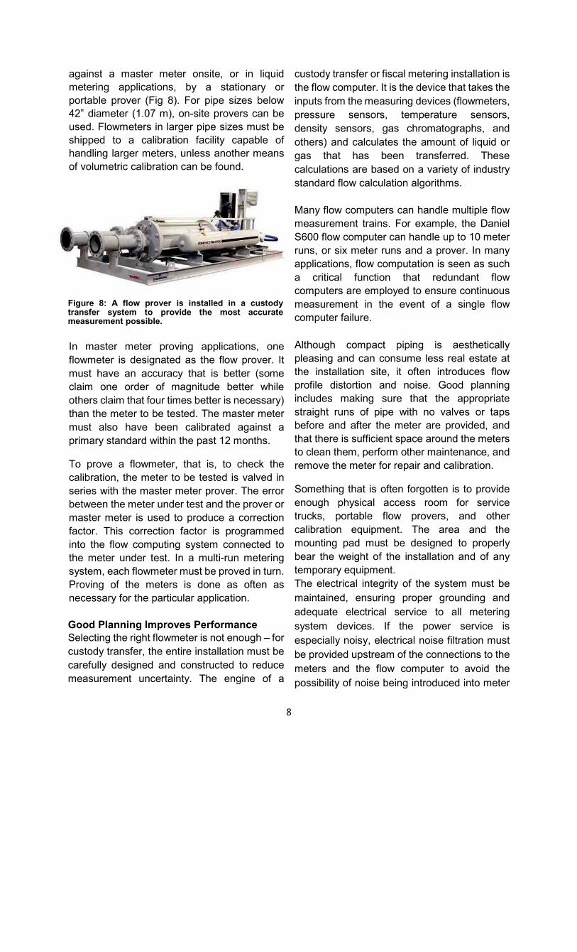
against a master meter onsite, or in liquid
metering applications, by a stationary or
portable prover (Fig 8). For pipe sizes below
42” diameter (1.07 m), on-site provers can be
used. Flowmeters in larger pipe sizes must be
shipped to a calibration facility capable of
handling larger meters, unless another means
of volumetric calibration can be found.
Figure 8: A flow prover is installed in a custody transfer system to provide the most accurate measurement possible.
In master meter proving applications, one
flowmeter is designated as the flow prover. It
must have an accuracy that is better (some
claim one order of magnitude better while
others claim that four times better is necessary)
than the meter to be tested. The master meter
must also have been calibrated against a
primary standard within the past 12 months. To prove a flowmeter, that is, to check the
calibration, the meter to be tested is valved in
series with the master meter prover. The error
between the meter under test and the prover or
master meter is used to produce a correction
factor. This correction factor is programmed
into the flow computing system connected to
the meter under test. In a multi-run metering
system, each flowmeter must be proved in turn.
Proving of the meters is done as often as
necessary for the particular application.
Good Planning Improves Performance Selecting the right flowmeter is not enough – for
custody transfer, the entire installation must be
carefully designed and constructed to reduce
measurement uncertainty. The engine of a
custody transfer or fiscal metering installation is
the flow computer. It is the device that takes the
inputs from the measuring devices (flowmeters,
pressure sensors, temperature sensors,
density sensors, gas chromatographs, and
others) and calculates the amount of liquid or
gas that has been transferred. These
calculations are based on a variety of industry
standard flow calculation algorithms.
Many flow computers can handle multiple flow
measurement trains. For example, the Daniel
S600 flow computer can handle up to 10 meter
runs, or six meter runs and a prover. In many
applications, flow computation is seen as such
a critical function that redundant flow
computers are employed to ensure continuous
measurement in the event of a single flow
computer failure.
Although compact piping is aesthetically
pleasing and can consume less real estate at
the installation site, it often introduces flow
profile distortion and noise. Good planning
includes making sure that the appropriate
straight runs of pipe with no valves or taps
before and after the meter are provided, and
that there is sufficient space around the meters
to clean them, perform other maintenance, and
remove the meter for repair and calibration. Something that is often forgotten is to provide
enough physical access room for service
trucks, portable flow provers, and other
calibration equipment. The area and the
mounting pad must be designed to properly
bear the weight of the installation and of any
temporary equipment.
The electrical integrity of the system must be
maintained, ensuring proper grounding and
adequate electrical service to all metering
system devices. If the power service is
especially noisy, electrical noise filtration must
be provided upstream of the connections to the
meters and the flow computer to avoid the
possibility of noise being introduced into meter
9
and device signals. Other factors become
important when a prover is included in the
installation. For example, valves should be
designed as “double block and bleed.” This
prevents bleed-through of fluid past a leaky
valve, bypassing the prover and resulting in
proving errors. Entrained gas in liquid flow
streams must be eliminated as well. Likewise,
pockets of gas in a liquid stream can cause
metering error and/or damage to some types of
liquid meters. Metering Skids Because building a custody transfer or fiscal
metering system requires special expertise that
is often hard to find in-house in a typical end
user company, the best solution can often be
the purchase of a purpose-built metering skid. If
this option is selected, it is important to pick the
right supplier. The selected skid builder must
have extensive experience and knowledge of
flowmeter technologies, flow characteristics,
accepted meter proving practices and
technologies, government and agency
regulations, and much more.
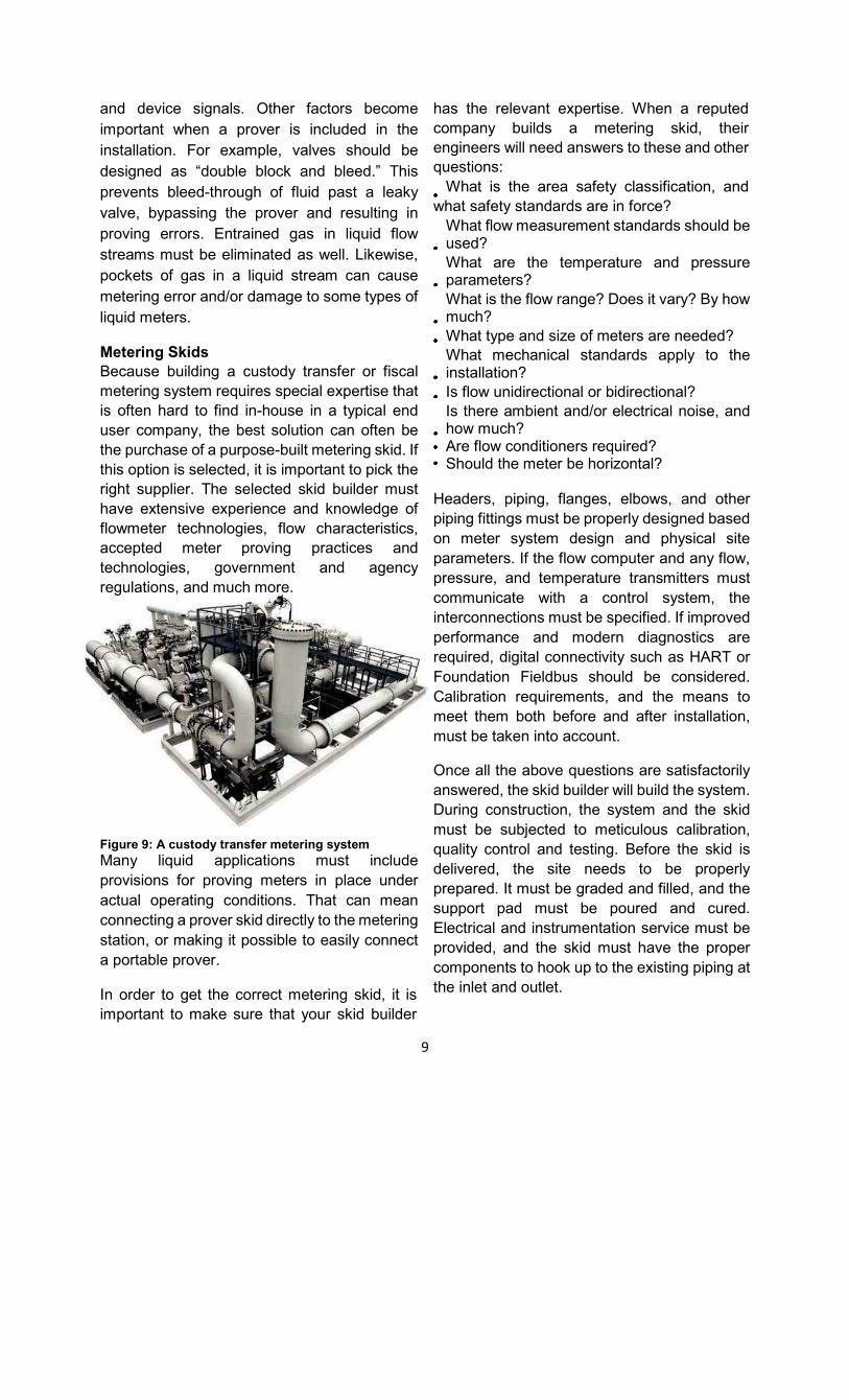
Figure 9: A custody transfer metering system
Many liquid applications must include
provisions for proving meters in place under
actual operating conditions. That can mean
connecting a prover skid directly to the metering
station, or making it possible to easily connect
a portable prover. In order to get the correct metering skid, it is
important to make sure that your skid builder
has the relevant expertise. When a reputed
company builds a metering skid, their
engineers will need answers to these and other
questions: What is the area safety classification, and
what safety standards are in force? What flow measurement standards should be used? What are the temperature and pressure parameters? What is the flow range? Does it vary? By how much? What type and size of meters are needed? What mechanical standards apply to the installation? Is flow unidirectional or bidirectional? Is there ambient and/or electrical noise, and how much? Are flow conditioners required? Should the meter be horizontal?
Headers, piping, flanges, elbows, and other
piping fittings must be properly designed based
on meter system design and physical site
parameters. If the flow computer and any flow,
pressure, and temperature transmitters must
communicate with a control system, the
interconnections must be specified. If improved
performance and modern diagnostics are
required, digital connectivity such as HART or
Foundation Fieldbus should be considered.
Calibration requirements, and the means to
meet them both before and after installation,
must be taken into account. Once all the above questions are satisfactorily
answered, the skid builder will build the system.
During construction, the system and the skid
must be subjected to meticulous calibration,
quality control and testing. Before the skid is
delivered, the site needs to be properly
prepared. It must be graded and filled, and the
support pad must be poured and cured.
Electrical and instrumentation service must be
provided, and the skid must have the proper
components to hook up to the existing piping at
the inlet and outlet.

10
After installation, the skid builder can
commission and startup the system, connect it
to the plant control system, perform initial
calibration testing if required, and provide
whatever training is required to operate and
maintain the metering station. Because
maintaining a metering skid is a specialized
operation, many skid builders provide ongoing
technical and complete lifecycle support.
Custody transfer is an exacting science that
requires expertise in a number of different
areas. For most companies, the best way to
procure, install, and operate a custody transfer
system is through partnering with an
experienced provider. Whether the custody
transfer system is built on-site or delivered on a
process skid, close cooperation between the
owner and the provider will result in the optimal
system for the particular application.

11
5.0 Issues in Calibration of Custody
transfer meters:
Orifice Meters:
Calibration of Orifice is deriving coefficient of
discharge “Cd”.
The largest contribution to the uncertainty in
the measured coefficient is due to the time
measurement.
In general, factors associated with orifice
installation affect the overall errors in flow
measurement. Errors are due to
uncertainties in, (a) flow equation, (b) actual
physical properties of the flowing fluid, and
(c) dimensions of the flow meter.
The flow rate is calculated from a number of
variables, the discharge coefficient,
expansion factor, differential pressure, bore
diameter, pipe diameter, and the fluid density
and viscosity, which are derived from
temperature and pressure values of the
flowing fluid. Therefore, actual fluid
properties should be monitored with best
possible precision.
The mechanical tolerances are critical for
measurement accuracy. The seat gap,
sealing material and dimensions, recesses
and protrusion, plate flatness and
eccentricity, tap location and machining
tolerances, etc., must conform to the
standard to achieve flow rate measurement
within the stated uncertainty of the standard.
Positive displacement Meters:
Caibration of positive displacement needs
the meter to be properly filled, air bled and
thermally stable before the prover runs are
made. It is very critical to maintain the
temperature of the meter under test same as
that of the master meter. The temperature
difference can be minimized by placing the
meter under test and the master meter as
close as possible.
Turbine Meters:
For turbine meters, the choice of calibration
fluid is particularly important. Turbine meters
are viscosity sensitive, and the figure below
shows some typical calibration results from a
turbine meter using water and three
petroleum products. Because of this
sensitivity to viscosity it is important to
calibrate these meters using a fluid as close
to the viscosity of working fluid as is
practicable. turbine meters, the choice of
calibration fluid is particularly important.
Turbine meters are viscosity sensitive. Fig10
shows some typical calibration results from a
turbine meter using water and three
petroleum products. Because of this
sensitivity to viscosity it is important to
calibrate these meters using a fluid as close
to the viscosity of working fluid as is
practicable.
Figure 10. Turbine meter performance
Coriolis Flow meters:
Verification diagnostic techniques have
rapidly advanced over the last five to 10
years and are continuing to improve. For
example, six meters are used in cavern
storage of hydrocarbons in western Canada
and were regularly proved, with some
random variation in meter factor but no
12
statistical change. More than $175,000 was
spent on these provings. As a result of data
such as this, Alberta, Canada’s energy
regulator created Directive 17, which states:
If a meter has built-in diagnostics to
continuously monitor the condition of the
primary element, inspection is not required
until an alarm or error is generated by the
meter or as recommended by the
manufacturer, such as in some types of
Coriolis meters. By using meter verification,
proving may be extended until the onboard
diagnostics advise it is time to prove. This will
result in significant savings in proving costs
during these extended proving intervals.
Some of the meters in this application were
upgraded to have modern diagnostics.
Several different Coriolis verification
methodologies are available. Some are
vendor independent, such as the
knowndensity method, while others are
proprietary. Some require stopping the flow
or stopping the process measurement to
perform the verification. Others are more
time consuming and may require a hot-work
permit. Some can be done in situ without
stopping flow or the flow measurement.
Verification methodologies can include
measuring and trending process
measurements, looking at internal
parameters such as drive gain and pickoff
amplitude, and using additional hardware
internal or external to the transmitter to verify
flow measurement. The user can perform
many of these techniques, and others
require a service technician visit by the
vendor.
The perfect flow meter — zero calibrations,
zero proving, no zeroing, zero worries with
powerful diagnostics that can verify meter
accuracy and give advance warning of
changes — does not yet exist. Coriolis flow
meters, however, are largely insensitive to
fluid properties. The author predicts that
within 10 years, on-board meter verification
diagnostics will be a standard expectation in
Coriolis technology. Verification will not
replace proving or calibration, but it can, and
is already, extending intervals. Proving and
calibration are often regulated by legal and
contractual arrangements. Verification is
recognized by a growing number of
agencies.
Ultrasonic Flow meters
Multipath ultrasonic gas flow meters are
normally flow calibrated at an accredited flow
laboratory before installation in order to verify
the flow meter’s performance and to correct
for flow meter offset. The common practice is
to install gas flow meters without in‐situ
calibration arrangement. Many of these flow
meters are never recalibrated. It is therefore
important to ensure that the flow meters are
calibrated properly with the highest degree of
confidence to the involved parties.
Preparations: The upstream pipe which will
be installed with the flow meter or an identical
pipe spool with the same length and inner
diameter must be used for the flow
calibration in order to provide similar flow
profile during calibration as will be expected
at the final installation site. If a flow
conditioner is part of the final installation, this
flow conditioner must also be used during
calibration.
The calibration laboratories have limited test
runs available with flange type and rating
designed for the maximum pressure at the
facility. Adapter spools are therefore often
required to match the line size and flange

13
type of the flow meter.
The calibration laboratories use their own
pressure and temperature transmitters in
order to conform to their accredited
procedures. The flow meter or the adjacent
pipe spools of the same line size should have
a pressure tapping to allow for connection of
the laboratory’s pressure sensor. This is
particularly important if the laboratory lines
size is different than the flow meter size.
For instance, if a 6‐inch flow meter is
installed in a 12‐inch test pipe, the pressure
in the 6‐inch flow meter will be lower than the
pressure in the 12‐inch pipe due to higher
gas velocity in the flow meter.
It is also important to supply the bolts and
gaskets required for the flow meter,
upstream pipe and adapter spools.
Most calibration laboratories will require a
pressure test certificate before installing the
flow meter and test spools into their
laboratory.
References:
[1] “Custody Transfer: The Value of Good
Measurement And The Search for the Truth”,
July 2009, Pipeline and Gas Journal (Author,
Daniel Rudroff)
[2] AGA Report no. 9, 2007
[3] Ultrasonic Flowmeters for custody
transfer (Author, Jesse Yoder)
[4] ASGMT2004, Overview of AGA.
[5] Understanding the Different Standards
that Govern Measurement (Author, Ronald E
Beaty)
[6] Good Practice Guide: The Calibration Of
Flow Meters (National Measurement
Systems)
[7] Cunningham, T. In Situ Verification of
Coriolis Flowmeters, Paper #13-0148, CsHm
2013, Calgary, AB Canada.
[8] flowcontrolnetwork.com/qa-a-roundtable-
discussion-on-flowmeter-calibration/
Presenting author Biodata

14
Name : Ms. Pranali Salunke
Designation : Dy. Manager – O&M
Company : Mahanagar Gas Ltd.
Qualification : Bachelor of Engineering
Area of Expertise : Instrumentation
Significant Achievements: 8 years of experience in different sections of City Gas
Distribution like maintenance of regulating station,
compressor and dispenser operations, procurement of
CNG equipment and spares, budgeting and inventory
control.
Number of Papers Published in Journals: NIL
Number of Papers Published in Conferences: NIL