Curved Steel I-girder Bridge LFD Guide Specifications Steel I-girder Bridge LFD Guide Specifications...
69
Curved Steel I-girder Bridge LFD Guide Specifications (with 2003 Edition) C. C. Fu, Ph.D., P.E. The BEST Center University of Maryland October 2003
Transcript of Curved Steel I-girder Bridge LFD Guide Specifications Steel I-girder Bridge LFD Guide Specifications...

Curved Steel I-girder BridgeLFD Guide Specifications
(with 2003 Edition)
C. C. Fu, Ph.D., P.E.The BEST Center
University of MarylandOctober 2003
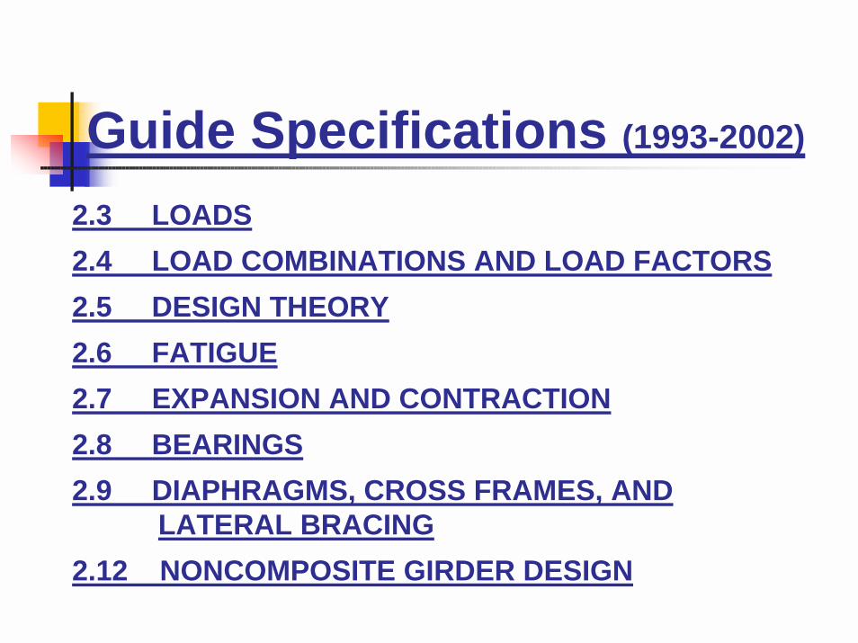
Guide Specifications (1993-2002)
2.3 LOADS2.4 LOAD COMBINATIONS AND LOAD FACTORS2.5 DESIGN THEORY2.6 FATIGUE2.7 EXPANSION AND CONTRACTION2.8 BEARINGS2.9 DIAPHRAGMS, CROSS FRAMES, AND
LATERAL BRACING2.12 NONCOMPOSITE GIRDER DESIGN

** 2003 New Guide Specifications
Section 2 Limit StatesSection 3 LoadsSection 4 Structural AnalysisSection 5 Flanges with One WebSection 6 WebsSection 7 Shear ConnectorsSection 8 BearingsSection 9 I –GirdersSection 11 Splices and ConnectionsSection 12 DeflectionsSection 13 Constructibility

** 2003 New Guide Specifications Section 2
2.2 STRENGTH LIMIT STATE (same as 2002; LFD only)
2.3 FATIGUE LIMIT STATE(use modified AASHTO LRFD Art. 6.6.1 with load factor of0.75 instead; Uncracked section is used as per Art. 9.6.1)
2.4 SERVICEABILITY LIMIT STATE(same as 2002; Deflection and Concrete Crack Control)
2.5 CONSTRUCTIBILITY LIMIT STATE(This limit state considers deflection, strength of steel andconcrete and stability during critical stage of construction)

** 2003 New Guide Specifications Section 9
� Deflection- Max. Preferable Span-to-Depth Ratio
- Live Load Deflections
DLL+I < L/800
DLL+I+sidewalk < L/1000
** Effective for the full width and full length of the concrete deck
y
as
FdL 5025=

2.3 LOADS
! Uplift must be investigated, without reduction for multiple lane loading and during concrete placement
AASHTO 3.17 Check D + 2 (L + I)and 1.5 (D + L + I)
AASHTO 10.29.6 Anchor bolts
! Impact same as current AASHTO
( I = 50 / (L + 125) ≤ 0.3 AASHTO Eq. 3.1 )**
** Revised in 2003.

** 2003 New Guide Specifications Section 3
! Impact
Art. 3.5.6.1 I-Girders.
Art. 3.5.6.2 Box Girders.
Art. 3.5.6.3 Fatigue - 15%
0.250.30Reactions, shear, cross frame and diaphragm actions0.200.25Girder bending moment, torsion and deflectionsLaneVehicle
Impact FactorLoad Effect
0.350.40Reactions, shear, cross frame and diaphragm actions0.300.35Girder bending moment, torsion and deflectionsLaneVehicle
Impact FactorLoad Effect

2.3 LOADS (cont.)
! Centrifugal Force same as current AASHTO
( C = 0.00117 S2 D = 6.68 S2 / R AASHTO Eq. 3.2 )( S = the design speed in miles/hr )
! Thermal Forces do not have to be considered if temperature movements are allowed to occur (more in Article 1.6 & 1.7)
! Superelevation redistribution of wheel load

2.4 LOAD COMBINATIONS AND LOADFACTORS
(A) Construction Loads (Construction Staging)1.3 (Dp + C)
(B) Service Loads (Stress range values and live load deflections)
D + LrwhereLr = L + I + CFL = Basic live loadI = Impact loadsCF = Centrifugal force
(C) OverloadsD + 5/3 Lr

2.4 LOAD COMBINATIONS AND LOADFACTORS (cont.)
For all loadings less than H20Group IA: 1.3 [D + 2.2 Lr] (Single lane)Group II: 1.3 [D + W + F + SF + B + S + T]
(EQ may replace W and ICE may replace SF)Group III: 1.3 [D + Lr + 0.3W + WL + F + LF]
(D) Maximum Design LoadsGroup I: 1.3 [D + 5/3 Lr]
For uplifting reaction:1.3 [0.9D + 5/3 Lr]

2.5 DESIGN THEORY
! General
� Analysis should be of entire structure� However, primary bending moment curvature effects may
be neglected if the following conditions exist:
5o4o5 or more
4o3o3 or 4
3o2o2
2 or more Spans1 Span
Limiting Central AngleNo. of Girders

2.5 DESIGN THEORY! Torsion Diaphragms must be
provided and designed as primary members
! Nonuniform Torsion otherwise known as �warping� or �lateral flange bending,� this effect always must be taken into account
! Composite Design may be used, but shear connectors must be designed using procedures that will be discussed at a later point

** 2003 New Guide Specifications Section 5
The effects of curvature may be ignored if! Girders are concentric,! Bearing lines are not skewed more then 10 degrees from radial,
and! The arc span divided by the girder radius is less then 0.06
radians where the arc span, Las, shall be taken as follows:
For simple spans:Las = arc length of the girder,
For end of spans of continuous members:Las = 0.9 times the arc length of the girder,
For interior spans of continuous members:Las = 0.8 times the arc length of the girder.

** 2003 New Guide Specifications Section 4
Simplified formula for the lateral bending moment in I-girder flanges due to curvature.
Eq. (4-1)
Where:
Mlat = lateral flange bending moment (k-ft)M = vertical bending moment (k-ft)
= unbraced length (ft)R = Girder radius (ft)D = web depth (in)
RDMMlat 5
6 2l=
l

** 2003 New Guide Specifications Section 4
Methods (Art. 4.3)
! Approximate Methods:� V-Load method for I-girder bridges� M/R Method for Box-girder bridges
! Refined Methods:� Finite Strip method.� Finite Element method.
(including gird model considering torsional warping)

DESCUS Alternate Solution for Torsion and Warping Differential Equations
φφω
′′′−′= 2
1aEC
M
GJMZ
aZC
aZBA +++= sinhcoshφ
Equation & Solution for Concentrated Torsion M
Equation & Solution for Uniform Torsion m
Equation & Solution for Linear Varying Torsion m
ω
φφECm
a−=′′′−′′2
1
GJmZ
aZD
aZCBZA
2sinhcosh
2
−+++=φ
ω
φφLECmZ
a−=′′′−′′2
1
GJLmZ
aZD
aZCBZA
6sinhcosh
3
−+++=φ

DESCUS Alternate Solution for Torsion and Warping Differential Equations
Fixed-Fixed End Solution for Uniform and Linear Varying Torsion m
Reference: �Torsion Analysis� published by Bethlehem Steel

DESCUS Alternate Solution for Torsion and Warping Differential Equations
Fixed-Hinged End Solution for Uniform and Linear Varying Torsion m

DESCUS Alternate Solution for Torsion and Warping Differential Equations
Stresses induced by Torsion & Warping
φτ ′= GttFormula 1
Formula 2
Formula 3
tES s
sφτ ω
ω′′′−=
φσ ω ′′= nss EW

DESCUS Alternate Solution for Torsion and Warping Differential Equations
Stresses induced by Bending
IyM b
b =σ
Formula 4
Formula 5
ItVQ
b =τ

2.5 DESIGN THEORY (cont.)
� Overload **
(fb + fw)overload < 0.8 Fy noncomposite< 0.95 Fy composite
** Modified in 2003 New Specifications Art. 9.5 Permanent Deflections as
(fb )overload < 0.95 Fy Continuously braced flanges &partially braced tension flanges
(fb )overload< Fcr1 = Fbs ρw ρs < 0.95 Fy
Partially braced compression flange
(fb,web comp. )overload<y
w
cr F
tD
EkF ≤
= 2
9.0

2.6 FATIGUE
� Same as Straight Bridge except for the contribution of torsional stress
� AASHTO Standard Spec.� Allowable Fatigue Stress Range
(Redundant or nonredundant; stress cycles & stress category)
� Stress cycles� Stress category
� AASHTO LRFD (** 2003 New Guide Specs.)� Infinite fatigue life (ADTT single-lane $ 2000 Trucks/day
Fn = (∆F)threshold� Finite fatigue life (ADTTsingle-lane < 2000)
Fn = ∆F = ( A/N )1/3

** 2003 New Guide Specifications Section 4
" Fatigue LoadDesign truck only with constant 30' between 32-kip axles. (LRFD Art. 3.6.1.4 with a load factor of 0.75)
ADTTsingle-lane = p x ADTTwhere p = 1.0 for one-lane bridge
= 0.85 for two-lane bridge= 0.80 for three-lane or more bridge
Class of Highway ADTT/ADTRural Interstate 0.2Urban Interstate 0.15Other Rural 0.15Other Urban 0.10

** 2003 New Guide Specifications Section 4
Fatigue Limit State
( ()f) # ()F)n (LRFD Eq. 6.6.1.2.2-1)
Infinite Fatigue Life (ADTTsingle-lane $ 2000 trucks/day)High traffic volume
Fn = ()F)threshold = 24 ksi for Category A16 B12 BN10 C12 CN7 D4.5 E2.6 EN

** 2003 New Guide Specifications Section 4
�Fatigue Limit State (cont.)Finite Fatigue Life (ADTTsingle-lane < 2000 trucks/day)
( )THFNAFFn ∆≥
=∆=
213
1
( )( )( )( ) lanesingleADTT75365 −= nN
Category A ()F)TH(ksi)
n
A 2.5 H 1010 24 R > 40! R < 40!
B 1.2 H 1010 16 Simple-span 1.0 2.0
BN 6.1 H 109 12
C 4.4 H 109 10 Continuous
CN 4.4 H 109 12 (1) Interior 1.5 2.0
D 2.2 H 109 7 Support
E 1.1 H 109 4.5 (2) Elsewhere 1.0 2.0
EN 3.9 H 108 2.6

2.7 EXPANSION AND CONTRACTION
Must allow thermal movements to take place in directions radiating from fixed supports
2.8 BEARINGS
! Must permit horizontal movements in directions radiating from fixed supports
! Must allow angular rotation in a tangential vertical plane
! Must hold down in cases of uplift
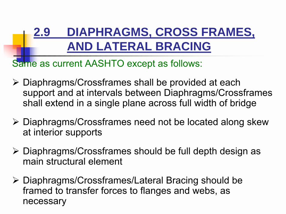
2.9 DIAPHRAGMS, CROSS FRAMES,AND LATERAL BRACING
Same as current AASHTO except as follows:
! Diaphragms/Crossframes shall be provided at each support and at intervals between Diaphragms/Crossframes shall extend in a single plane across full width of bridge
! Diaphragms/Crossframes need not be located along skew at interior supports
! Diaphragms/Crossframes should be full depth design as main structural element
! Diaphragms/Crossframes/Lateral Bracing should be framed to transfer forces to flanges and webs, as necessary

2.9 DIAPHRAGMS, CROSS FRAMES,AND LATERAL BRACING (cont.)
Suggested Diaphragm/Crossframe spacingCenterline Radius Suggested Max.of Bridge (feet) Spacing (feet)
Below 200 15200 to 500 17500 to 1000 20Over 1000 25
2.9 (B) Lateral BracingMax. stress of the bottom lateral wind bracing
�b = �d × (DF)bR
�d = Max. Stress in Crossframes from grid analysis
( ) ( )( )
DFSD L
SGLR
Lbl
=− + −
×
+ +
2 5016 10
1600 6524 3.
../

** 2003 New Guide Specifications Section 9
Intermediate cross frames should be spaced as nearly uniform as practical to ensure that the flange strength equations are appropriate. Equation (C9-1) may be used as a guide for preliminary framing.
Eq. (C9-1)
Where:= cross frame spacing (ft)
= desired bending stress ratio,
= girder radius (ft)= flange width (in)
fRbrσ365=l
l
σrR
fb
bffl

** 2003 New Guide Specifications Section 5
Eq. (5-1)
where:Fy = specified minimum yield stress (ksi)
When fb is greater than or equal to the smaller of 0.33Fy or 17 ksi, then:
Eq. (5-2)
The unbraced arc length, l, in feet between brace points at cross frames or diaphragms shall satisfy the following:
Eq. (5-3)where:b = minimum flange width in the panel (in)R = minimum girder radius within the panel (ft)
yFf 5.0≤l
5.0≤bffl
10/ and 25 Rb ≤≤l

2.12 NONCOMPOSITE GIRDER DESIGN(B) Maximum Normal Flange Stress
! Compact Sections
� Compression Flange
Requirement: (** New: 18)
Allowables:
whereFbs = Fy (1 - 3 λ2)
where
** 2003 New Guide Specs use the same equation, except l/bf in all the equations to be consistent with the units used
bt Fy
≤ 3200
F Fcr bs B w1 = ρ ρ
λ π=
1 12lb
FEy
Eq. (5-4)
** Revised in 2003

2.12 NONCOMPOSITE GIRDER DESIGN(cont.)
ρb
f fb b R
=
+ +
−
1
112
12
60 01
2l l l
.** Revised in 2003
ρρ
ww
b
f
bbs
y
Rff
R b
FF
= + −
+
−
0 95 18 01
0 3 122
. .
. .l
l l
** Revised in 2003
ρ ρB w ≤ 10.
� Tension Flange
fb < Fbu = Fy** Superseded

** 2003 New Guide Specifications Section 5
−=
==
3
ρρsmaller
2
1
lfFF
FFF
ycr
wbbscr
cr
" Compact Compression (Art. 5.2.1)
(Eq. 5-4)
(Eq. 5-5)
� Fcr for Partially Braced Tension Flange is the same as Fcr for compact compression.
� Fcr for Continuously Braced Tension Flange is Fy

2.12 NONCOMPOSITE GIRDER DESIGN(cont.)
(B) Maximum Normal Flange Stress (cont.)! Non-Compact Sections
� Compression Flange
Requirement:
Allowables:fb # Fby = Fbs ρw ρs
(fb + fw) # Fy
whereFbs = Fy (1 - 3 λ2)
(Same definition for ρb and ρw)
� Tension Flange(fb + fw) # Fby = Fy
3200 4400F
bt Fy y
< ≤ ** Superseded
** Superseded

** 2003 New Guide Specifications Section 5
" Non-Compact Compression (Art. 5.2.2)
Eq. (5-7)
Eq. (5-8)
Eq. (5-9)
( ) 2302.1 ≤+
≤lff
Etb
bf
f
−==
=lfFF
FFF
ycr
wbbscrcr
2
1 ρρsmaller

** 2003 New Guide Specifications Section 5
f
b
bR 75121
1ll+
=ρ
−−
=
fb
w
bff
751211
11
ll
ρ
+
−+
+
=
b
f
w
ff
R
b
l
l
l
6.01
1.0000,830
12
95.0 2
2ρ
** Revised in 2003
** Revised in 2003
** Revised in 2003
When ρw = min(ρw1, ρw2); , ρw = ρw10≥bffl 0<bffl

** 2003 New Guide Specifications Section 5
" Partially Braced Tension Flanges (Art. 5.3)
Eq. (5-10)
Eq. (5-11)
" Tension Flanges and Continuously Braced Flanges (Art. 5.4)
Fcr = Fy
−=
==
3
ρρsmaller
2
1
lfFF
FFF
ycr
wbbscr
cr
−=
==
3
ρρsmaller
2
1
lfFF
FFF
ycr
wbbscr
cr

** 2003 New Guide Specifications Section 6
" Unstiffened Web (Art. 6.2)for R ≤ 700 feet
Eq. (6-1)
for R > 700 feet
Eq. (6-2)
Where:D = distance along the web between flanges (in)tw = web thickness (in)R = minimum girder radius in the panel (ft)
100≤wtD
( ) 150700038.0100 ≤−+≤ RtD
w

** 2003 New Guide Specifications Section 6
" Web Bending Stresses (Art. 6.2.1. 6.3.1, & 6.4.1)
Eq. (6-3)
where:k = bend-duckling coefficient
= 7.2 (D/Dc)2 for unstiffened webs= 9.0 (D/Dc)2 for transversely stiffened webs
= for longitudinally= stiffened webs
Dc = depth of web in compression (in)ds = distance between long. stiffener and comp. flange (in)
y
w
cr F
tD
EkF ≤
= 2
9.0
4.0)(17.5 2 ≥=c
s
s Ddfor
dDk
4.0)(64.11 2 <−
=c
s
sc Ddfor
dDDk

(C) Web Design! Webs Without Stiffeners
Vu = C Vp
whereVp = 0.58 Fy D t
for
C = 1.0
for
2.12 NONCOMPOSITE GIRDER DESIGN(cont.)
Dt
KFw y
< 6 000,
6 000 7 500, ,KF
Dt
KFy w y
≤ ≤
C KDt
Fw
y
=
6 000,

2.12 NONCOMPOSITE GIRDER DESIGN(cont.)
Dt
KFw y
> 7 500,
C KDt
Fw
y
= ×
4 5 107
2
.
for
where buckling coefficient K = 5
** 2003 New Guide Specs use the same equation, except E is included in all the equations to be consistent with LRFD format.

** 2003 New Guide Specifications Section 6
" Transversely Stiffened WebsD/tw < 150For R ≤ 700 feet
Eq. (6-7a)
For R > 700 feet
Eq. (6-7b)
where:R = minimum girder radius in the panel (ft)
Ddo =
( )[ ] DDRdo 370000154.00.1 ≤−+=

2.12 NONCOMPOSITE GIRDER DESIGN(cont.)
! Transversely Stiffened GirdersVu = C Vp
(Calculations for C and Vp are the same as for webs without stiffeners except
! Requirements for Transverse StiffenersI # do t3 J
where
KdDo
= +
5 52
J Dd
Xo
=
−
2 5 22
.

** 2003 New Guide Specifications Section 6
" Transverse Web StiffenersWidth-to-Thickness Ratio Requirement
Eq. (6-13)
Where:ts = stiffener thickness (in)bs = stiffener width (in)Fy = specified minimum yield stress of stiffener (ksi)
ys
s
FE
tb 48.0≤

** 2003 New Guide Specifications Section 6
Moment of Inertia Requirement
Eq. (6-14)where:
J = Eq. (6-15)
X = 1.0 for a ≤ 0.78 Eq. (6-16)
X = Eq. (6-17)
a = aspect ratio
=
Z = Eq. (6-18)
do = actual distance between transverse stiffeners (in)R = minimum girder radius in the panel (ft)
JtdI wots3=
5.02/58.1 2
≥
−
X
Dd
4
775,178.01 Za
−+
Ddo
10079.0 2
≤w
o
Rtd

! Longitudinally Stiffened GirdersNot required if
One stiffener required (D/5 from the compression flange) if
Two stiffeners required (D/5 from both flanges) if
! Requirements for Longitudinal Stiffeners
2.12 NONCOMPOSITE GIRDER DESIGN(cont.)
Dt F
dR
dRy
o o≤ −
+
36 500 1 8 6 342, .
Dt F
dR
dRy
o o≤ − +
73 000 1 2 9 2 2, . .
Dt Fy
≤ 73 500,

** 2003 New Guide Specifications Section 6
" Longitudinal Web StiffenersMoment of inertia Requirement
Eq. (6-19)
where:β = when the longitudinal stiffener is on the side
of the web away from the center of curvature
β = when the longitudinal stiffener is on the side
of the web toward the center of curvature
1+
1+
( )β13.04.2 23 −≥ aDtI wsl
6Z
12Z

** 2003 New Guide Specifications Section 6
" When single transverse stiffeners are used, they preferably shall be attached to both flanges. When pairs of transverse stiffeners are used, they shall be fitted tightly to both flanges.
" Transverse stiffeners used as connection plates shall be attached to the flanges by welding or bolting with adequate strength to transfer horizontal force in the cross members to the flanges.
" Two longitudinal stiffeners may be used on web section where stress reversal occurs.
" Longitudinal and transverse stiffeners preferably shall be attached on opposite sides of the web.
" Bearing stiffeners shall be placed in pairs, bolted or welded to the girder web or diaphragm

CURVED COMPOSITE I-GIRDERS
2.13 GENERAL
2.14 EFFECTIVE FLANGE WIDTH
2.15 NONCOMPOSITE DEAD LOAD STRESSES
2.16 COMPOSITE SECTION STRESSES
2.17 SHEAR CONNECTORS

2.13 GENERAL
! Girders shall be proportioned for ordinary bending and for nonuniform torsion (also called warping or lateral flange bending)
! Usual moment of inertia method shall be used for bending
! Any rational method shall be used for nonuniform torsion
! For fatigue, perform stress analysis including bending and nonuniform torsion

2.14 EFFECTIVE FLANGE WIDTH
� AASHTO Standard Spec. (Art. 10.38.3;**2003 Art. 4.5.2)not to exceed:� ¼ of the span length of the girder� the distance center to center of girders� 12 x the least thickness of the slab
� AASHTO LRFD (Art. 4.6.2.6)For interior beams, the least of:� ¼ of the effective span length� 12 x the average thickness of the slab + greater of
(web thickness, ½ the width of the top flange of the girder)� the average spacing of adjacent beams

2.15 NONCOMPOSITE DEAD LOAD STRESSES
! (fb)DL1 # Fb determined from Art. 2.12 (B)
! (fb + fw)DL1 # Fy determined from Art. 2.12 (B)
!
where fDL1 = (fb + fw)DL1
** Revised in 2003, same equations for noncomposite and composite
bt f DLI
≤ 440013.

2.16 COMPOSITE SECTION STRESSES
! Compact within Concrete fb # Fy
! Noncompact, compression flange� braced by cross-frames or diaphragms
fb # Fby
fb + fw # Fy
� braced by concretefb + (fw)DL # Fy
** Revised in 2003, same equations for noncomposite and composite

2.17 SHEAR CONNECTORS
Same as current AASHTO for straight girders, except as modified by Article 1.19
(A)Fatigue(B) Ultimate Strength
** Covered in 2003 Section 7 � Shear Connectors

** 2003 New Guide Specifications Section 7
� - Strength
Eq. (7-1)
where:φsc = 0.85Su = strength of one shear connector according to AASHTO Article
10.38.5.1.2 (kip)P = force in slab at point of maximum positive live load moment
given by Equation (7-2) (kip)
Eq. (7-2)
SN
φ=
22
usc
P
pp FPP +=

** 2003 New Guide Specifications Section 7where:
= longitudinal force in the slab at point of maximum positive live load moment computed as the smaller of P1p or P2p from Equations (7-3) and (7-4) (kip)
= radial force in the slab at point of maximum positive live load moment computed from Equation (7-5) (kip)
Eq. (7-3)where:
As = area of steel girder (in2)
Eq. (7-4)
where:= specified 28-day compressive stress of concrete (ksi)
bd = effective concrete with as specified in Article 4.5.2 (in)td = average concrete thickness (in)
pP
pF
ysp FAP =1
′cf
ddcp tbfP ′= 85.02

** 2003 New Guide Specifications Section 7
Eq. (7-5)
where:Lp = arc length between an end of the girder and an
adjacent point of maximum positive live load moment (ft)
R = minimum girder radius over the length, Lp (ft)
" Between MLL+ and MLL
- -Eq. (7-6)
where:= longitudinal force in the concrete slab at point of greatest
negative live load moment computed from Equation (7-7) (kip)
= radial force in the concrete slab at point of greatest negative live load moment computed from Equation (7-10) (kip)
RL
PF pPp =
22TT FPP +=
TP
TF

** 2003 New Guide Specifications Section 7
Eq. (7-7)
where:= the smaller of P1n or P2n (kip)
Eq. (7-8)
Eq. (7-9)
Eq. (7-10)
where:Ln = arc length between a point of maximum positive live load
moment and an adjacent point of greatest negative live load moment (ft)
R = minimum girder radius over the length, Ln (ft)
npT PPP +=
nP
ysn FAP =1
ddcn tbfP ′= 45.02
RLPF n
TT =

** 2003 New Guide Specifications Section 7
- Fatigue
Eq. (7-11)
where:Vfat = longitudinal fatigue shear range/unit length (k/in)Ffat = radial fatigue shear range/unit length (k/in)
Eq. (7-12)
where:Abot = area of bottom flange (in2)σflg = range of fatigue stress in the bottom flange (ksi)
= distance between brace points (ft)R = minimum girder radius within the panel (ft)w = effective length of deck (in)
( ) ( )2fat
2fat FVVsr +=
wRσA
Flflgbot
fat =
l

** 2003 New Guide Specifications Section 7
Eq. (7-13)
where:FCR = net range of cross frame force at the top flange (kip)
Eq. (7-14)
where:n = number of shear connectors in a cross sectionZr = shear fatigue strength of an individual shear connector
determined as specified in AASHTO LRFD Article 6.10.7.4.2 (kip)
Vsr = range of horizontal shear for fatigue from Equation (7-11) (kip)
wFF CR=fat
sr
r
VnZp =

CURVED HYBRID GIRDERS
2.18 GENERAL
2.19 ALLOWABLE STRESSES
2.20 PLATE THICKNESS REQUIREMENTS
** not covered in 2003 new Guide Specifications

2.18 GENERAL
! Pertains to hybrid I-girders having a vertical axis of symmetry through the middle-plane of the web plate

2.19 ALLOWABLE STRESSES(A) Bending-Noncomposite Girders! Allowable flange stress
Equal to allowable stress from Article 2.12 multiplied by reduction factor
where Fy = yield strength of compression flange
( ) ( )( )R
BB
= −− ′ − + ′
+ −1
1 36 3
2Ψ Ψ ΨΨ Ψ
α α
B = web areatension flange area
Ψ = C of tension flangedepth of section

2.19 ALLOWABLE STRESSES (Cont.)
( )′ = +α α 1 f fw b t/
α = web yield strengthtension flange yield strength
= absolute value of (lateral flange bending stress / bending stress) for tension flange
f fw b t/
If , then R = 1f fw b t/ ≥ −1 α
α

2.19 ALLOWABLE STRESSES (Cont.)(B) Bending � Composite Girders
! Allowable flange stress � positive moment regionSame as for noncomposite girder
! Allowable flange stress � negative moment regionSame as for noncomposite girder, except α is defined as follows:
T
T
when ffw
b c
≤ −−
′ =2 11Ψ
Ψ, α α
( )when 2 11 1
1ΨΨ
ΨΨ
−−
< <−
−ffw
b cα

2.19 ALLOWABLE STRESSES (Cont.)
′ = + −
α α 1 1f
fw
b c
ΨΨ
where is the same as ff
ff
w
b c
w
b t
except that it is for the compression flange
( )if , then R = 1ffw
b
≥−
−ΨΨα 1
1

2.19 ALLOWABLE STRESSES (Cont.)
! Shear (same as homogeneous section in Art. 2.12(C)
Vu = C Vp
! Fatigue
Same as current AASHTO for straight hybrid girders

2.20 PLATE THICKNESS REQUIREMENTS
! Web plate thickness requirements
Same as for non-hybrid curved girders, except that fb in the formulas is replaced by fb / R
! Flange plate thickness requirements
Same as for non-hybrid curved girders

THE END
Questions ??