CURVED BARS - University of Texas at Austinoden/Dr._Oden_Reprints/...Curved bars, such as those used...
20
STIFF~~SS ANALYSIS OF SHARPLY CURVED BARS 008 SooM 4063-1 J. T. ODEN
Transcript of CURVED BARS - University of Texas at Austinoden/Dr._Oden_Reprints/...Curved bars, such as those used...
STIFF~~SS ANALYSIS OF SHARPLY
CURVED BARS
008
SooM 4063-1 J. T. ODEN
( GENERAL DYNAMICS/FORT WORTHA Division of General Dynamics Corporation
May 1964
SooM 4063-1
Subject:
1.0 General
Memorandum Report
Stiffness Analysis of Sharply Curved Bars
(
Curved bars, such as those used in fuselage construction,are usually analyzed as planar thin rings and the influence ofthe initial curvature is assumed to be negligible. The as-sumption is justifiable in most cases, and the analysis isr~latively simple and straightforward. When applied to theanalysis of curved elements in air-intakes, engine mounts,wing edges, and some fuselage rings, however, the thin ringtheory may lead to appreciable error in the stress distributionand a more refined theory must be used. In addition, the crosssections of such rings are seldom sy~metrical with respect tothe plane of the ring and the influence of unsymmetricalbending should be accounted for.
In this report, a stiffness matrix is presented for theanalysis of torsionally weak, unsymmetrical rings of smallcurvature. It is shown that the thin ring theory is a specialcase of general relationships derived herein.
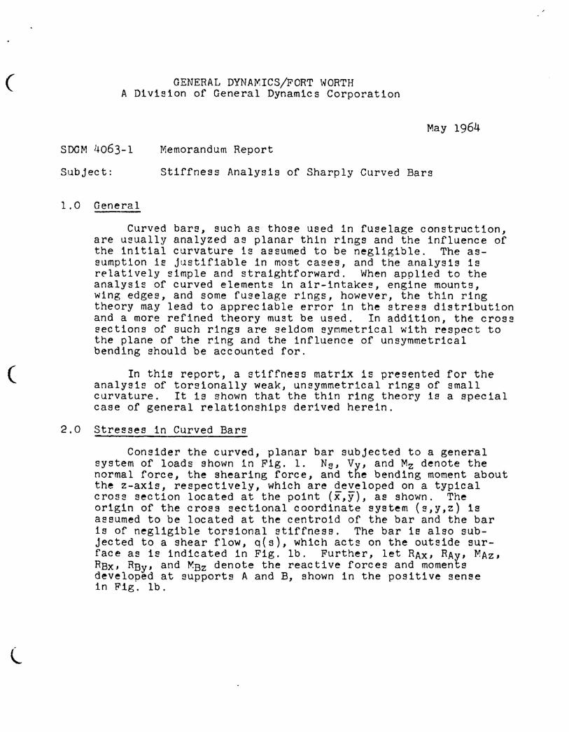
2.0 Stresses in Curved Bars
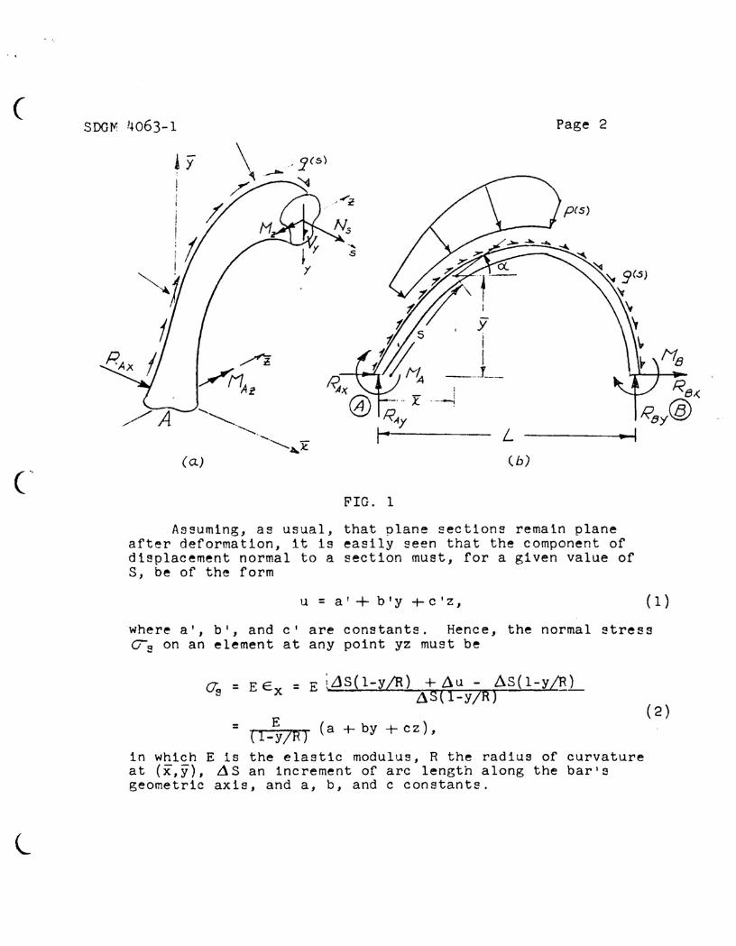
Consider the curved, planar bar subjected to a generalsystem of loads shown in Fig. 1. Ns, Vy, and Mz denote thenormal force, the shearing force, and the bending moment aboutthe z-axis, respectively, which are developed on a typicalcross section located at the point (x,y), as shown. Theorigin of the cross sectional coordinate system (s,y,z) isassumed to be located at the centroid of the bar and the baris of negligible torsional stiffness. The bar is also sub-jected to a shear flow, q(s), which acts on the outside sur-face as is indicated in Fig. lb. Further, let RAx, RAy, MAz,RBx, RBy' and ~Bz denote the reactive forces and momentsdeveloped at supports A and B, shown in the positive sensein Fig. lb.
(SooM !·w63-l
!yI
/A
( a.)
FIG. 1
L(b)
Page 2
N8~Rex.
RBy®.. I
Assuming, as usual, that plane sections remain planeafter deformation, it is easily seen that the component ofdisplacement normal to a section must, for a given value ofS, be of the form
u = a' + b'y +c'z, (1)
where a', b', and ct are constants. Hence, the normal stress~s on an element at any point yz must be
Os = E Ex
l
= E LLlS(l-y/R) +L\u - ~S(l-y/R)L\S( l-Y/R) -
= E (a + by + c z) ,
in which E is the elastic modulus, R the radius of curvatureat (x,y), ~S an increment of arc length along the bar'sgeometric axis, and a, b, and c constants.
(2 )
( SoofY! 4063-1 Page 3
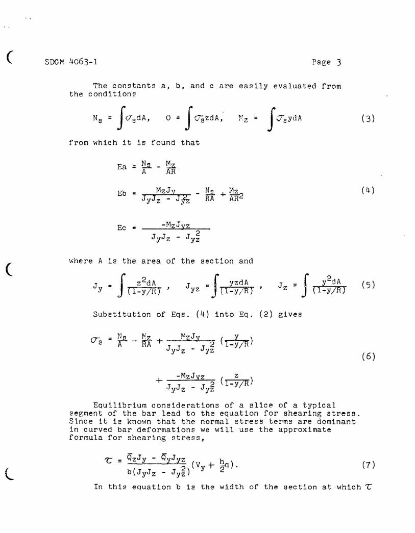
The constants a, b, and c are easily evaluated fromthe conditions
o • f <7;jzdA, 1"z = f vaydA
(
from which it is found that
Ea=&-~A AR
~here A 1s the area of the section and
Jyz = f yzdA( l-y iR) , J z = f .'y2d.~ •
( 4 )
(5 )
Substitution of Eqs. (4) into Eq. (2) gives
+ -MzJyz z.TyJz - Jy~ (l-v/R)
Equilibrium considerations of a slice of a typicalsegment of the bar lead to the equation for shearing stress.Since it i~ known that the normal stress terms are dominantin curved bar deformations we will use the approximateformula for shearing stress,
(6)
l't: = QzJy - QyJyz h
2 (Vy+ ~).b(JyJz - Jyz)
In this equation b is the width of the section at which ~
r' ..
( SDGiil 4063-1 Page 4
is to be evaluated, h is the depth of the section, and
(8)
AI beln~ the area of the section to one side of the levelat which ~ is to be evaluated, as in the elementary theory.
The influence of radial stresses and Poisson's ratioon final deflections is assumed to be negligible.
3.0 Statics
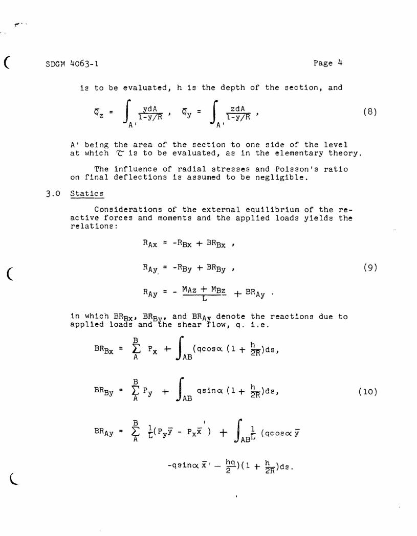
Considerations of the external equilibrium of the re-active forces and moments and the applied loads yields therelations:
RAx = -RBx + BRBx '
( RAy. = -RBy + BRBy , (9)
RAy = - MAz + MBz + BRAyL
in which BRBx' BRBy, and BRAy denote the reactions due toapplied loads and the shear flow, q. i.e.
B J hBRBx = L. Px + (qcoscx.(1 + 2lt)ds,A AB
B+ J qslncx (1 + ~)dS.BRBy = r. Py
A AB(10)
l-qsincxx' - ~q)(l + ~R)dS.
( SDGM 4063-l Page 5
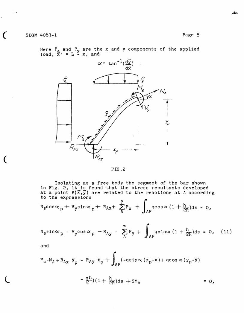
Here p~ and Py are the x and y components of the appliedload, Xl = L - x, and
1 -ex= tan- (dY)dX"
P +~ ~:1f'J(
tv!l:----N~
TYp
~f/11
RAX
(.I' I -- .,
~ x.p.-----
( ~)'
FIG.2
Isolating as a free body the segment of the bar shownin Fig. 2, it is found that the stress resultants developedat a point p(x,y) are related to the reactions at A accordingto the expressions
NscosC\'p+VysinC\'p+ RAx+ fPx + IAPqCOSO<(l+~R)dS' 0,
~.
and
Mz-MA+RAx Yp - RAy Xp+ JAP(-QSlnO«(Xp-X)+qCOSC\'(Yp-Y)
l q.!:!. h- ~)(l + 2ji)ds +SMs = 0,
(
· .
SDG?·!4063-1 Page 6
l
4.0
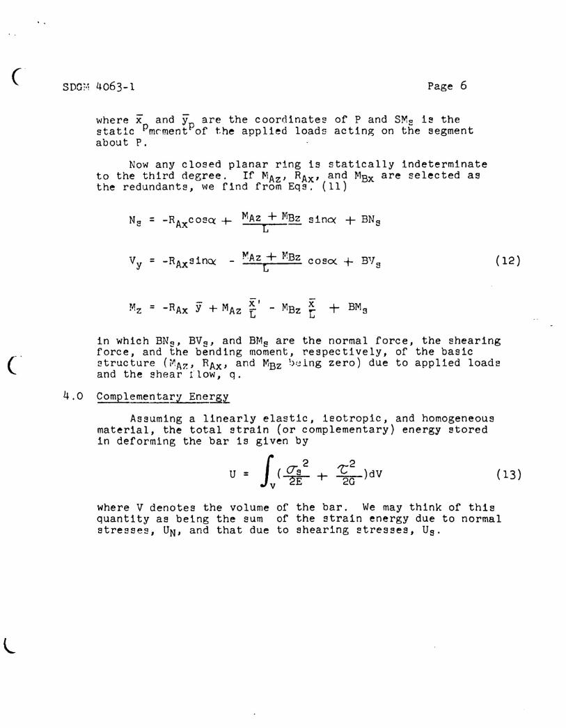
where x and yare the coordinates of P and SMa i8 thestatic Pm~mentPof the applied loads acting on the segmentabout P.
Now any closed planar ring is statically indeterminateto the third degree. If MAz' RAx' and MBx are selected asthe redundants, we find from Eqs. (ll)
Ns = -RAxcosQ: + MAz + MBz sinO( + BNL s
Vy = -RAxsinQ( - !V!Az+ MBz cosO( + BV s (l2)L
!i1z = - RAx y + MAz ~ I - MBz x + BMsL t
in which BNQ, BVQ, and BMQ are the normal force, the shearingforce, and the bending moment, respectively, of the basic~tructure (MAz, RAx' and MBZ b~lng zero) due to applied loadsand the shear flow, q.
Complementary Ene~l
Assuming a linearly elastic, isotropic, and homogeneousmaterial, the total strain (or complementary) energy storedin deforming the bar is given by
f 2 2U = (eTs + ~)dV (13)
v 2"E 2G
where V denotes the volume of the bar. We may think of thisquantity as being the sum of the strain energy due to normalstresses, UN' and that due to shearing stresses, Us.
(SDGM 4063-1 Page 7
(16)
(
Now the volume of a differential element of the baris (l-y!R)dsdA, so that on substituting Eq. (6) into Eq. (13)the strain energy due to normal stress becomes
J 11 {~ 2NsMz [- 1-. Jy y + Jyz z ]UN = s A 2E A2 + A RA +N(l-Y/R) N(l-y!R)
22 [1 2Jy (y :J1L y 2 2J yz z
Mz ff -frRA l-y/R)+ N (l-Y/R) + NRA (l-y/R) (14)
where
(15)
Recalling that ~YdA and ~ZdA are zero, Eq. (14) becomes,-after some algebraic manipulations,
J [ 1 2 2J JUN = ~(Nx-Mz!R) + ~ dss 2EN
Similarly, on substituting Eq. (7) into Eq. (13) wearrive at the following expression for the strain energy dueto shear:
(17 )
in which Jt is the shear shape factor given by
l(18)
( SDGM 4063-1 Page 8
Physically, dt may be interpreted as a conversion factorby which the average shearing stress must be multiplied inorder to give the "exact" shear deformation of a section.For th1nwalled sections ~ is close to unity; for a rectangularsection of large curvature R, '~ is 6/5. Since the sheardeformation of a ring i= usually a few percent of that dueto bending, ~ is frequently taken as unity without a signi-ficant loss in accuracy.
The total strain energy, of course, is UN + Us.
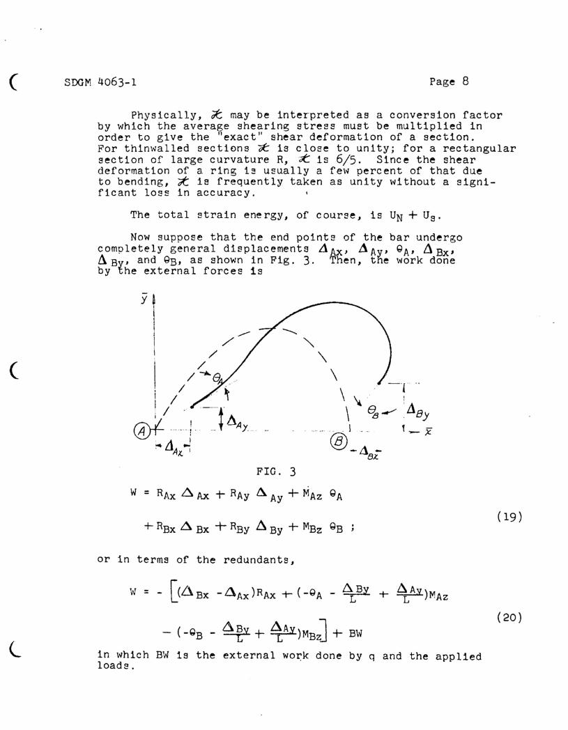
Now suppose that the end points of the bar undergocompletely general displacements LiAx, J1Ay' QA' ~ Bx'~BY' and QE, as shown in Fig. 3. Then, the work doneby the external forces 1s
(
.Y ~
\I! /--I /
// -"a
, / /'I I ~~.~@lm_l __tt1AY
~Ll .J)1x. I
"" \\ ,- -'I ..
\ \ 'e' ---- ! .18J\ B '
,- - I '.- t __ x'.'''@, B A_
-UB..t
FIG. 3
W = RAx ~ Ax + RAy ~ Ay + MAz Q A
or in terms of the redundants,
- (-QB - ~~y + L£AY)MBJ + B\v
in which BW 1s the external wo~k done by q and the appliedloads.
(19)
(20)
c·
..
SDGM 4063-1 Page 9
Finally, according to Reference 2, the total comple-mentary p.nergy of the system is
,---
Il = U - W = UN + Us - W.
5.0 Equations of Consistent Deformation
Compatibility of resultant internal and external dis-placement~ 1s established by employing the principle ofminimum complementary energy, i.e., the magnitudes of RAxMAz and MBz must be such that the total complementaryenergy is a minimum. Therefore,
(21)
onv ~Az = (22)
(By substituting Eqs. (12) into Eqs. (16) and (17) we
may obtain the total strain energy in terms of the redundantsand the applied loads. If we operate on the resulting functionas is indicated in Eqs. (22), we obtain the final equationsof consistent deformation:
"TI = 0 = MAzFll + MBzF12 + RAxF13-GA _1,AY - 1BY+ '(;AB
(23)
l
r-:'
all =0=oRAx
(Soot-'1 4063-1 Page 10
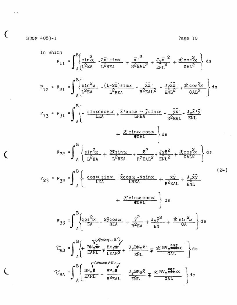
1n wh1eh B{_2 -2 K 2}F - J sin~ _2x'sino<
II - + x I + JyX I +' cos C( d sL2EA L2REA R2EAL2 ENL2 GAL2
A ....
F = F = SBJsin'h _(L-2x)s1n<>. _ xx' _ Jyxx' +t:eos~ } d.12 21 ALL2EA L2REA R2EAL2 ENL2 GAL2
F = F 1 =SB~- sin<xeosO( +x'eos", + ys1nO( _ YX' _ Jyj013 3 LEA LREA R2EAL ENL
AL
+ X s 1nc< COS"" } dotGAL ...
B
( F22 =J {s1 n2", t- 2xsin:x -2 J-2 + iteos~ } dsx + YX
A L2EA L2REA + R2EAL2 ENL2 GAL2
F = P =JB t coso< sinO( xeo.", -ysim"(24)
--+ J':f:xy+ xy
23 32 LEA - LREA R2EALA ENL
+ cKsina:.coscx 1. dIGAL f S
:.."
F =JB{eOS2
<x 2yc 080( -2 -2 + 1:: sin 2C( ld s- + ..:L- + JyY33 EA REA R2EA EN GA !A . J
B \.(R5In<t-~/l .J { - - - cos}T. = + BN~Y _ BMs~' JyBMsx' _ -k. BVs~C( dsAB EARL ..LEAR2 + ENL'" GAL
A
~ '\ (/?stnct rZ ) 7l 'L, =fB ~ ENsI BI'st JyBl':sX _ X BVs~C<
}dS""BA - - ...EARL R2EAL ENL' GALA '--
( SDGM 406'1-1 Page II
sin }BV8~~ dsGA
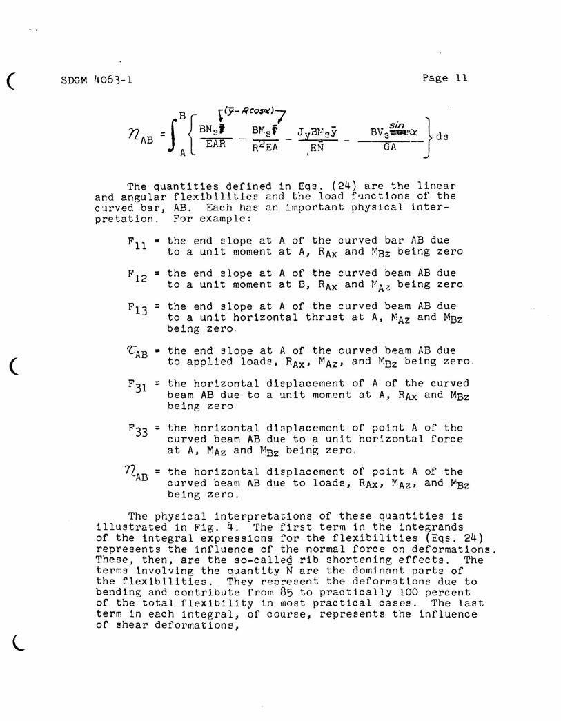
flAB =
(
l
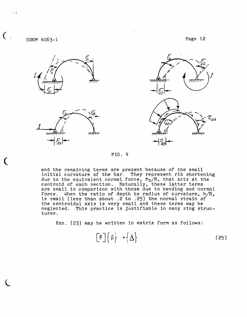
The quantities defined in Eqs. (24) are the linearand angular flexibilities and the load f~nctions of thec~rved bar, AB. Each has an important physical inter-pretation. For example:
Fll • the end slope at A of the curved bar AB dueto a unit moment at A, RAx and MBz being zero
= the end slope at A of the curved bea~ AB dueto a unit moment at B, RAx and VAZ being zero
= the end slope at A of the curved beam AB dueto a unit horizontal thrust at A, MAz and MBzbeing zero.
~AB • the end slope at A of the curved beam AB dueto applied loads, RAx' MAz, and MBz being zero.
= the horizontal displacement of A of the curvedbeam AB due to a unit moment at A, RAX and MBzbeing zero.
= the horizontal displacement of point A of thecurved beam AB due to a unit horizontal forceat A, MAz and MBz being zero.
the horizontal displacement of point A of thecurved beam AB due to loads, RAx, ~Az' and MBzbeing zero.
The physical interpretations of these quantities isillustrated in Fig. 4. The first term in the inte~randsof the integral expressions for the flexibilities (Eqs. 24)represents the influence of the normal force on deformations.These, then, are the so-calleg rib shortening effects. Theterms involving the quantity N are the dominant parts ofthe flexibilities. They represent the deformations due tobending and contribute from 85 to practically 100 percentof the total flexibility in most practical cases. The lastterm in each integral, of course, represents the influenceof shear deformations,
(,300M 4063-1
1v///
r11
'1'tT1T'r
--/f~
Page 12
(
1
FIG. 4
l
and the remaining terms are present because of the smallinitial curvature of the bar. They represent rib shorteningdue to the equivalent normal force, Mz/R, that acts at thecentroid of each section. Naturally, these latter termsare small in comparison with those due to bending and normalforce. When the ratio of depth to radius of curvature, h/R,is small (less than about .2 to .25) the normal strain ofthe centroidal axis is very small and these terms may beneglected. This practice is justifiable in many ring struc-tures.
Eqs. (23) may be written in matrix form as follows:
(25)
· .
( SDGM 4063-l Page 13
wherer
Fll Fl2 F13
[FJ - F2l F22 F23 I . (25a)-
F3l F32 F33
1-' f\) 'M R ~",p ( = "'Az' "'Bz' Azr... ) L .I J
(25b)
and
j-~ 1\ ,·u·I.. J = (25c)
( ~ y • ~ By - /;1Ay' b.. x = ~ Bx - 6. Ax
and 'CAB' LBA' and nAB are temporarily taken as zero.
(25d)
Since the final flexibilities amount to 2imply thealgebraic sum of those due to normal force, ~hear, andbending, and also from the above physical interpretationgiven each term, we sp.e that the flexibility matrix givenin Eq. (25a) can be represented as the sum of three flexibilitymatrices; one whose elements are flexibilities due to Ns,another with elements the flexlbillties due to bending, anda third flexibility matrix whose elements are deformationsdue to shear. Mathematically,
(26)
For example, the element Fll may be written
l(26a)
( SDG\'w~ 4063-1
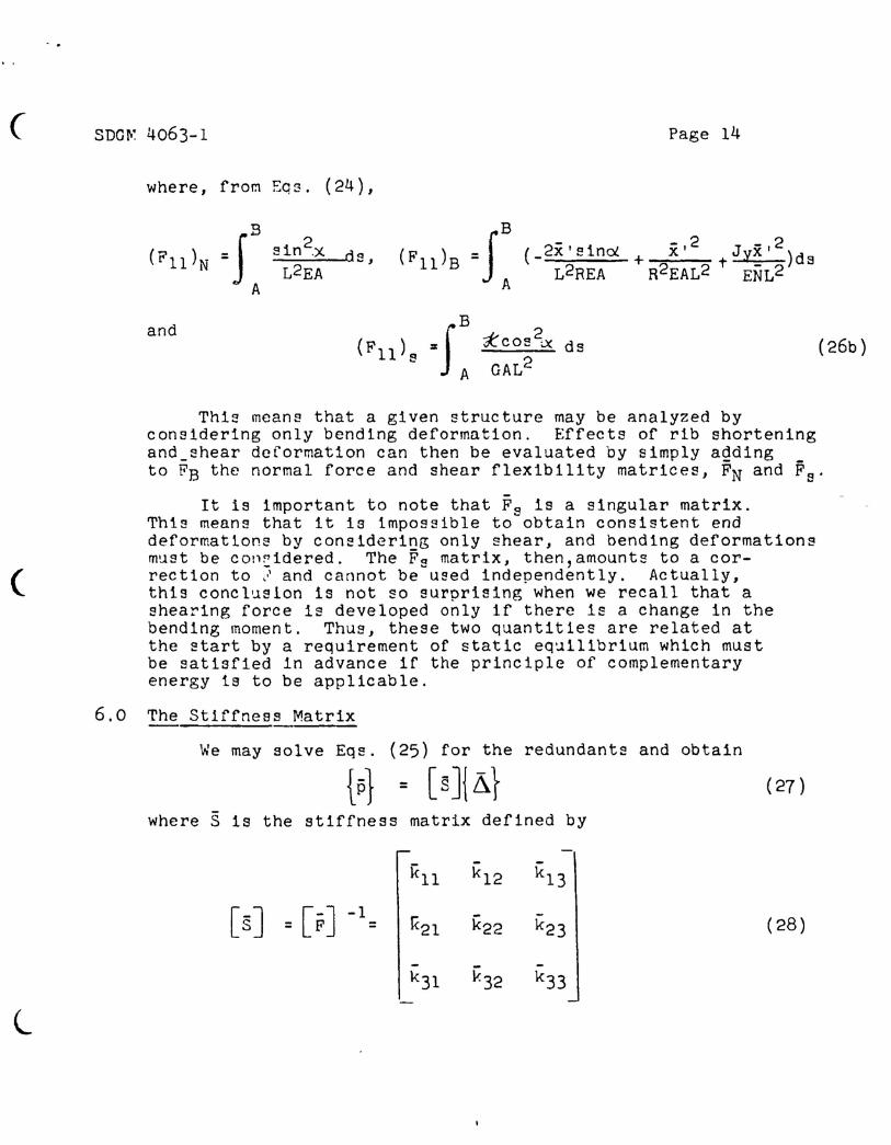
where, fro~ Eqs. (24),
Page 14
de,
B-f (_2x'sinol(Fll)B - A L2REA
and 2i::cos ~ ds
GAL2(26b)
(
l
6.0
This means that a given structure may be analyzed byconsidering only bending deformation. Effects of rib shorteningand_shear deformation can then be evaluated by simply agding _to FB the normal force and shear flexibility matrices, FN and Fs'
It is important to note that F~ is a singular matrix.This means that it is impossible to~obtain consistent enddeformations by considering only shear, and bending deformationsm~st be con~idered. The Fs matrix, then, amounts to a cor-rection to ! and cannot be ueed independently. Actually,this conclusion is not so surprising when we recall that ashearing force is developed only if there is a change in thebending moment. Thus, these two quantities are related atthe start by a requirement of static equilibrium which mustbe satisfied in advance if the principle of complementaryenergy 1s to be applicable.
The Stiffness Matrix
We may solve Eqs. (25) for the redundants and obtain
{is1 = [s]{Li} (27 )
where S is the stiffness matrix defined by
kl1 k12 kl3
[sJ [-J -1 K21 k22 k23 I= F = (28)
- -k3l K32 k33
( SDGrJi4063-1
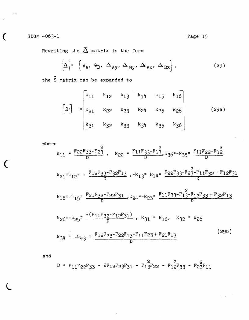
Rewriting the Ll matrix in the form
~ f ':/1 .-: I-I. ~A' QB' ~AY' ~BY' ~AX' 6l.BXJ'! !
-the S matrix can be expanded to
kll k12 k13 k14 k15 k16
[~ J = k21 k22 k23 k24 k25 k26
k31 k32 k33 k34 k35 k36
where
Page 15
(29)
(29a)
and
= F12F23-F22F13-Fll F23 + F21F13D
(29b)
l
(
· ,
SDGr.~4063-l
so that Eq. (25) may be written
Page 16
.. 1, I
: p r (30)
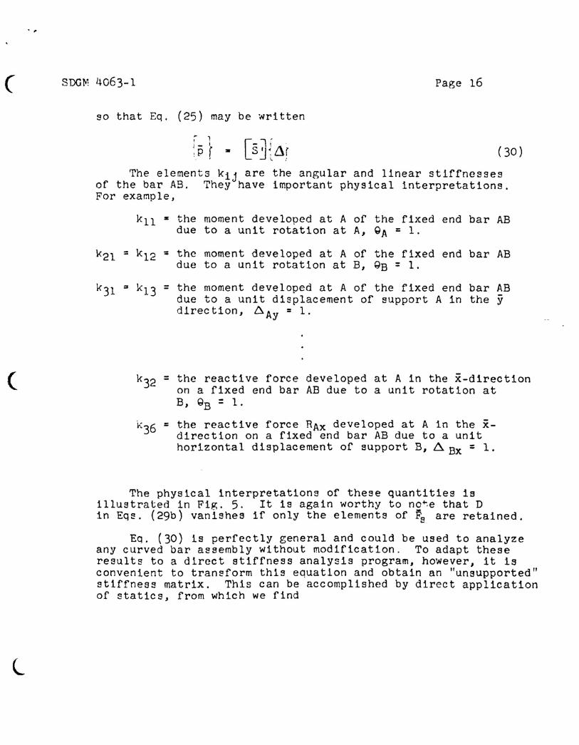
The elements kij are the angular and linear stiffnessesof the bar AB. They have important physical interpretations.For exa~pleJ
kll • the moment developed at A of the fixed end bar ABdue to a unit rotation at A, QA = 1.
the moment developed at A of the fixed end bar ABdue to a unit rotation at B, QB = 1.
(
l
the moment developed at A of the fixed end bar ABdue to a unit displacement of support A in the ydlrec tion, ~ Ay = 1.
= the reactive force developed at A in the x-directionon a fixed end bar AB due to a unit rotation atB, QB = 1.
= the reactive force RAx developed at A in the x-direction on a fixed end bar AB due to a unithorizontal displacement of support B, ~Bx = 1.
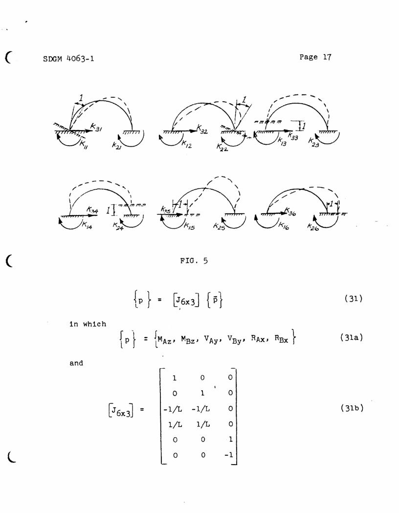
The physical interpretations of these quantities isillustrated in Fig. 5. It is again worthy to no~e that Din Eq~. (29b) vanishes if only the elements of Fs are retained.
Eq. (30) is perfectly general and could be used to analyzeany curved bar assembly without modification. To adapt theseresults to a direct stiffness analysis program, however, it isconvenient to tran~form this equation and obtain an "unsupported"stiffness matrix. This can be accomplished by direct applicationof statics, from which we find
( SOOM 4063-1 Page 17
( FIG. 5
{p } = ~6X3J {p 1 (3l),
in which
{p 1 = {MAZ' MBz, VAy' VBy' RAx, RBX} (31a)
andr -
1 0 0,
0 1 0
[J6x31 = -l/L -l/L 01 (31b)
l/L l/L 0
0 0 1
l I 0 0 -1
(
- ,
SDGtwl 4063-1 Page 18
Finally, introducing EQ. (31) into Eq. (30), we obtain
= [s] ~J (32 )
where S is the 6x6 unsupported stiffness matrix for thecurved bar:
7.0 Thermal Effects
[sJ r JI! s ,;L .J ~ -J
(33)
The influence of thermal gradients, shear flowe, appliedloads, and a number of other special effects may be easilyaccounted for by determining the proper values of ~AB' ~BA'and I~AB in the vector
"Yl 1I l..ABJ (34 )
It is merely necessary to determine end displacementsof the statically determinate bar for each effect. Forexample, to account for a nonlinear thermal gradient overeach cross section T(x,y,z) we neglect ~hear deformationand replace BMs and BNs in Eqs ..(24) by NT and ~ where
NT • f eSdA, M.:r. f e,;I'ydA r' (35 )
and add to 71AB ~h~ term - e,2'L. The .yector ~,-T:Tr for thi Bcase is written -J CAB)T' ('-BA)TI (/t.AB)T J . The thermalloads developed at node points is then gIven by
l
~..,
[sJ ; Tr{p~ - 'I.. ,
where
JT~ = [J]{TTt!. J
(36 )
(37 )
(, SDGM 4063-1 Page 19
Written by: \ ..---..\ r\ C....._ . • '>. ;' ,'}," , I...J. 1t'. Oden -'" /., ....
. c.:~-. .~-;.J t
Chec ked by: /:. ../ .......~~.•I/.· ./;:: • ::A i
l
Approved by: J) fJ f!vlr-h.!-lJ-t-R. P. Peloubet


![adventure on a Grand Scale. THE AUTHENTIC DIFFERENCE you ...€¦ · Bars (sold separately). [F] Water Sports Carrier transports kayaks, sailboards or surfboards with flat or curved](https://static.fdocuments.in/doc/165x107/5fba4e37c0650311576fe2c0/adventure-on-a-grand-scale-the-authentic-difference-you-bars-sold-separately.jpg)