CURVE TRACER SERIES 5000 SEMICONDUCTOR TESTER
15
CURVE TRACER SERIES 5000 SEMICONDUCTOR TESTER
Transcript of CURVE TRACER SERIES 5000 SEMICONDUCTOR TESTER

CURVE TRACER SERIES 5000SEMICONDUCTOR TESTER

1
CONTENTSCURVE TRACER SERIES 5000 - 1
SEMICONDUCTOR TESTER PERFORMANCE - 3
STANDARD CURVES - 4PROGRAMMING - 6
CURVE SUITE - 12CURVE EXAMPLES - 14
WEIGHT AND DIMENSIONS - 17SELECTING A TESTER - 17TEST SPECIFICATIONS - 18
PRODUCT LIST - 20CLIENT LIST - 24
Scient i f ic Test , Inc . , 1 1 10 E . Col l ins Blvd. , #130, Richardson, TX 75081972.479. 1300 | sc i test .com
CURVE TRACER SERIES 5000FUNCTIONThe Curve Tracer Series 5000 provides all of the functions of the 5000E and 5300HX with the ability to create digital curves for storage and intuitive manipulation.
Curves are generated using high speed ATE test steps to build the curve point by point. Precision data points are generated quickly and accurately using an STI 5000C or 5300C Test System. Data increments are programmable in linear or logarithmic steps. Curves are generated rapidly. Typical test time per step is 6 to 20MS. A two hundred data point curve will typically take only a few seconds to generate. Captured curve data points can be loaded into Excel® to create curve trace presentations.
• PC Based• Wide Selection of Available Curves• Programmable Data Point Increments• Increments can be Linear or Logarithmic• Programmable Off-Time to Minimize Heating• Save and Recall Curve Entry Programs• Save and Recall Previously Captured Curve Image• Load Curve Data Directly to Excel• Run up to 10 Curve Programs in Sequence with data
loaded to Excel Automatically• Program Maximum Current/Voltage Limits to Prevent
Damage or Heating• Store/Recall Test Programs• Multiple Sequential Curves• Multiple Devices• Current Limit in Test Program
• Logarithmic Curves• Easy to Use
•Select Curve•Enter Range•Press Start
• Full Range of Current (not limited to 20A)• Graph Features - Tools
•Scales Axes•Change Log/Linear•View Data Points on Curve•Zoom•Print Graph•Set cursors for new sweep•Save Graph
• No Patch Cords• No SMU Set-Up-Selection; Completely Automatic
Optional tests can be created for connection to external test equipment.For Curve Tracer specifications refer to Discrete Semiconductor Tester 5000E & 5300HX brochure.Windows® is a registered trademark of Microsoft Corporation. Excel® is a registered trademark or trademark of Microsoft Corporation.

32
PROGRAMMINGProgramming a curve is simple and straightforward. Select desired curve on the menu and fill in the blanks.
Model 5300C
RANGESVOLTAGE
• 1KV Standard, 2KV Optional• .20V Gate/Base; 80V Optional
CURRENT • 2NA to 50A, 100A Optional• Optional: 20PA
OPTIONAL• 100/500/1000/1200A
RESOLUTION • 1MV• 0.1NA• 0.1 Milliohm RDSON• Test Fixtures
PERFORMANCEThe Series 5000 Curve Tracer provides quick creation of digital curves for storage and intuitive manipulation. Curves are generated using a high speed ATE system.
High resolution assures tests like RDSON to an accuracy of ± 0.5 milliohm at 1 A test current.
LabView® is a registered trademark or trademark of National Instruments.
Model 5000C

54
STANDARD CURVESAdditional curves can be added using any test available. These include but are not limited to transistor, triac, SCR, MOSFET, IGBT, OVP, gated device, diode, zener, opto-coupler, regulator, MOV, J-FET, opto-switch, diac, opto-logic, Quadrac®, sidac, STS, SBS, and relay.
MOSFET N-Channel• ID vs. VDS (at range of VGS)• ID vs. VGS (at range of VDS)• IS vs. VSD• RDSON vs. VGS (at fixed ID)• RDSON vs. ID (at several VGS)• IDSS vs. VDS (Reverse Bias Selectable)• VGSTH vs. ID
MOSFET P-Channel• ID vs. VDS (at range of VGS)• ID vs. VGS (at range of VDS)• IS vs. VSD• RDSON vs. VGS (at fixed ID)• RDSON vs. ID (at range of VGS)• IDSS vs. VDS (Reverse Bias Selectable)• VGSTH vs. ID
Transistor NPN• HFE vs. IC• BVCE (O, S, R, V) vs. IC• BVEBO vs. IE• ICBO vs. VCBO• VCE (SAT) vs. IC (at fixed IC/IB ratio)• VCE (SAT) vs. IB (at range of IC)• VBE (SAT) vs. IC (at fixed VCE)• IC vs. VCE (at range of IB) (Curve Tracer Only)• IEBO vs. VEB• ICEO vs. VCE
Transistor PNP• HFE vs. IC• BVCE (O, S, R, V) vs. IC• BVEBO vs. IE• ICBO vs. VCBO• VCE (SAT) vs. IC (at fixed IC/IB ratio)• VCE (SAT) vs. IB (at range of IC)• VBE (SAT) vs. IB (at fixed IC/IB ratio)• VBE (ON) vs. IC (at fixed VCE)• IC vs. VCE (at range of IB) (Curve Tracer only)• IEBO vs. VEB• ICEO vs. VCE
IGBT N-Channel• IC vs. VCE (at range of VGE)• IC vs. VGE (at range of VCE)• ICES vs. VCE• IF vs. VF• VCE vs. VGE
IGBT P-Channel
• IC vs. VCE (at range of VGE)• IC vs. VGE (at range of VCE)• ICES vs. VCE• IF vs. VF• VCE vs. VGE
CURVE TRACER CURVES AVAILABLEDiode
• IF vs. VF• IR vs. VR
Zener• IF vs. VF• IZ vs. BVZ
Triac• IT vs. VT+ (at fixed IG and RGK open)• IT vs. VT- (at fixed IG and RGK open)
SCR• IT vs. VTM (at fixed IG and RGK open)
SSOVP• IT vs. VT+ (at fixed IBO)• IT vs. VT- (at fixed IBO)
SIDAC• IT vs. VT+ (at fixed IBO)• IT vs. VT- (at fixed IBO)
DIAC• ID vs. VF+• ID vs. VF-
Regulator Positive• Electronic Load vs. VOUT (at fixed IMAX)
Regulator Negative• Electronic Load vs. VOUT (at fixed IMAX)
JFET N-Channel• ID (OFF) vs. VDS (at range of VGS)• ID (OFF) vs. VGS (Reverse Bias) (at fixed VDS)• ID (ON) vs. VDS (at range of VGS)• ID (ON) vs. VGS (Reverse Bias) (at fixed VDS)
JFET P-Channel• ID (OFF) vs. VDS (at range of VGS)• ID (OFF) vs. VGS (Reverse Bias) (at fixed VDS)• ID (ON) vs. VDS (at range of VGS)• ID (ON) vs. VGS (Reverse Bias) (at fixed VDS)
Other Curves• V vs. I Quadrants I and III

76
Programming the data points on the curve tracer is simple and direct. Fig. 1 shows an IDON vs VDS program screen for an N-Channel MOSFET. The maximum limit for the measured variable, IDON, is the top line entry. When the maximum limit is reached, data capture terminates and the curve is complete. The horizontal axis is VDS and is programmable in increments. Two different increment sizes can be programmed. This allows the user to program finer data points in the area of interest in the curve. In the example shown, the first increment size is 400 MV; the second increment size is 4V. The increment size changes at VDS of 4V. VDS range is programmed from
10MV to 40V. VGS data points can be programmed similarly. The curve is run by sweeping the VDS data points at each VGS bias voltage and continues until the maximum ID is obtained at each VGS or until all data points have been reported.
Additional tabs provide user selectable features. Tabs can be selected by clicking on a function near the top of the Curve Tracer screen: Load/Save for recall and saving programs, Sweep Type to select linear or logarithmic axes where appropriate, Ext. Relays to set relay drivers to connect external components, ADP-401A to set pin connections when the curve tracer is used with an
ADP-401A 8 or 16 pin programmable scanner, and Misc. Controls to load a completed curve and data points directly to Excel with the graph automatically included. The data points can also be graphed in other formats provided by Excel.
A number of graphing features are also included. The mouse can be used to zoom in on a specific area of the curve. Cursors can be moved on a completed curve to re-set start and stop limits to re-generate the curve in greater detail in an area of interest. Clicking on an axis will change the scale from linear to logarithmic. Clicking on a curve will show all data points on the curve.
PROGRAMMING
Other curves are similarly programmed. See examples that follow in Figures 2 thru 9.
Figure 1
Max ID Increment Change 2nd Increment
VDS End
VDS Start
VGS End
1st Increment
VGS Increment
VGS Start

98
HI Current MOSFET, ID vs VDS (Figure 4)
HI Current IGBT, IC vs VCE (Figure 5)
Hi-Deck Required
Hi-Deck Required
500A+
700A+
SiC IDSS vs VDS (Figure 2)
GaN FET, Bipolar Gate, IDON vs VDS (Figure 3)
400 NA
2KV
-3V VGS
+3V VGS
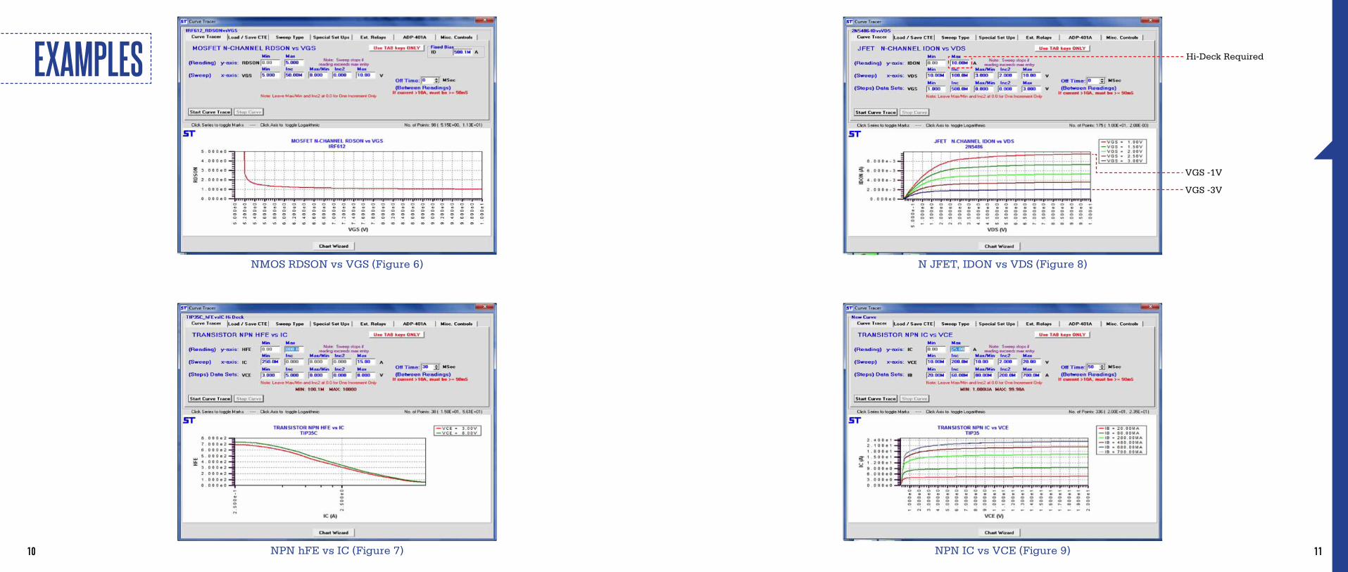
EXAMPLES
1110
N JFET, IDON vs VDS (Figure 8)
NPN IC vs VCE (Figure 9)
Hi-Deck Required
VGS -1V
VGS -3V
NMOS RDSON vs VGS (Figure 6)
NPN hFE vs IC (Figure 7)
EXAMPLES

1312
Figure 13
Figure 14
Figure 12
Figure 15
A suite of curves can be generated using a group of previously saved curve programs. The curves are run in sequence automatically without the intervention of an operator other than to start the curve sequence. See Figures 10 thru 15. Individual graphs are displayed on the screen as the curves are generated; curve data points are automatically loaded into Excel along with the captured graph. Graphs can be viewed in order by clicking the “View Next” button.
Figure 10 Figure 11
CURVE SUITE

1514
VGSTH vs ID IGBT ICES vs VCE
NPN VCESAT vs IC, IC/IB Fixed Ratio NPN ICBO vs VCB
CURVE EXAMPLES
IGBT Diode IF vs VF
NPN IC vs VCE
NPN VCE vs IB
IGBT IC vs VCE, 100A Option
500A

1716
SELECTING A TESTERQUESTIONS TO ASK• Is programming easy? Will vendor give you software to evaluate?• Are current and voltage ranges sufficient?• Can current/voltage ranges be extended later?• Are a wide selection of fixtures available?• Is test/datalog speed adequate?• Will vendor benchmark your samples for speed and correlation?• Is the test method “single measure”?• Does it include self-test with convenient troubleshooting guide?• Is auto-calibrate included?• Is vendor experienced? How many systems have they installed?• Is tester limited to single device type/family? (latent cost)• Is curve trace available?
WEIGHT AND DIMENSIONSMODEL DIMENSIONS (mm) WEIGHT (kg) POWER
MODEL 5000 SERIESTester Mainframe
17” (432) x 20” (508) x 10.5” (267) 55 lbs (25)120/240 VAC (+5%, -15%)50/61 Hz, Fused 2A/1A
MODEL LC-1000Lo Current Deck
16.5” (419) x 10.5” (267) x 8” (203) 11 lbs (5) Powered from 5000 Series Tester
MODEL HC-500Hi Current Deck
17” (432) x 20” (508) x 10.5” (267) 35 lbs (15.9) Powered from 5000 Series Tester
RACK MOUNT AVAILABLE
PNP VCE vs IB
Diode IF vs VF
PNP VBE vs IC, fixed VCE
JFET IDON vs VGS
CURVE EXAMPLES

1918
TEST SPECIFICATIONS
PARAMETER V RANGE I RANGE MAX RES. ACCURACY
LEAKAGE
IR, ICBO, ICEO/R/S/X, IDSS/X, IDOFF, IDRM, IRRM
.10V to 999V (2000V)1 2NA (20PA)2 to 50MA 1 NA (1PA)2 1% + 2NA + 20PA/V8
(1% + 200PA + 2PA/V)2,8
IEBO, IGSSF, IGSSR, IGSS, IGKO, IR (OPTO)
.10V to 20V (80V)3 2NA (20PA)2 to 3A 1 NA (1PA)2 1% + 2NA + 20PA/V8
(1% + 200PA + 2PA/V)2,8
BREAKDOWN
BVCEO, BVCES(IGBT)
(300μS Pulse above 10mA)
.10V to to 450V (900V)1
to 700V (1400V)1
to 800V (1600V)1
100μA to 200MAto 100MAto 50MA
1 MV 1% + 100MV
BVDSS, VD, BVCBO, VDRM, VRRM, VBB, BVR
.10V to 999V (2000V)1 100NA to 50MA 1 MV 1% + 100MV
BVZ
.10V to 5.00Vto 9.999Vto 50.00V
to 700V (1400V)1
to 999V (2000V)1
BVZ Soak - 50V (100V)0-50 ms to 99 secs
10μA to 49.9A (500A)4, 10
to 25A (250A)4, 10
to 9.99Ato 100 MAto 50MAto 400mAto 80mA
1 MV 0.4% + 2 LSB
BVEBO, BVGSS, BVGKO .10V to 20V (80V)3 100NA to 3A 1 MV 1% + 10MV
VCESUS VCEOSUS, VCERSUS, VCEVSUSVCE: TO 1500V
Inductive Kickback, 35mH choke
IC: to 4A 0.5V 2% + 0.5V
IMPEDANCEZZ (1 kHZ)
0.1Ω to 20 KΩ0.1V to 200V DC
(measure 50μV to 300mV rms) 100μA to 300mA DC0.001 Ω
1μV1% + 1% Range
GAIN
hFE (1 to 99,999)CTR (.01 to 99,999)
gFS, gFE
VCE: .10V to 5.00V5
to 9.99Vto 49.9V
VDS, ID: Same as ON STATE VGS: 0.1V to 20V (80V)3
IE: 10μA to 49.9A (99.9A)9 (500A)4, 10
derate to 25A (50A)9 (250)4, 10
derate to 9.99AIF, IB: 100NA to 10A
∆ID/∆VGS automatically computed
.01 hFE.0001 CTR
VCE: 1% + 10MVIC: 1% + 100NAIF, IB: 1% +5NA
TEST SPECIFICATION SPECIFICATION PARAMETER V RANGE I RANGE MAX RES. ACCURACY
ON STATE
VCESAT, VBESAT, VBEONVF, VT
VDSON, IDON, VGSONVGEON VF (Opto-Diode)
RDSON
VCE, VD, VF, VT: .10Vto 5.00Vto 9.99V
VGS, VGE, VBE, VF:.10V to 9.99V
1.00mΩ to 1KΩ
IE, VT, IF, ID: 10μAto 49.9A (99.9A)9 (500A)4, 10
derate to 25A (50A)9 (250A)4, 10
IB, IF, IGT: 100NA to 10A (40A)7
VDS, ID: Same as ON STATE VGS: 0.1V to 20V (80V)3
1MV
.01mΩ
V: 1% + 10MVIE, IF, ID, IT: 1% +
100NAIB, IGT: 1% + 5NA
VGSTH, VGETH .10V to 49.9V ID: 100μA to 3A 1MV 1% + 10MV
VO (Regulator)VO: .10V to 20V (50V)3
VIN: .10V to 49.9VLoad: Resistive or Electronic
IO: 1MA to 5A 1MV 1% + 10MV
IIN (Regulator)VIN: .10V to 20V (80V)3
Load: RGK, 1K, 10K,EXT, OPEN, SHORT
IIN: 1MA to 3A 10NA 1% + 5NA
VC .10V to 49.9V 10MA to 10A 1MV 1% + 10MV
OFF VGSOFF VO: .10V to 20V (80V)3 ID: 100NA (20PA)2 to 3AVDS: .10V to 50V 1MV 1% + 10MV
TRIGGERIGTVGT
VOPER (Relay)
VD: 5V to 49.9VVGT: .10V to 20V (80V)3
.10V to 50V
IAK: to 3AIGT: 100NA to 3A
RL: 12, 30, 100Ω, EXT
10NA1MV.10V
1% + 5NA1% + 10MV1% + .10V
HOLDIH
VRELEASE (Relay)VD: 5V to 49.9V
.10V to 50V
IH: 1.5AIGT: 100NA to 3A
RL: 12, 30, 100Ω, EXT(Initial IAK set by RL)
1µA.10V
1% + 2µA1% + .10V
LATCHIL
(Tested indirectly, no exact value)VD: 5V to 49.9V
IL: 100µA to 3AIGT: 100NA to 3A
RL: 12, 30, 100Ω, EXTN/A N/A
BREAKOVER
VBO, IBO (SSOVP)VBO, IBO (STS, DIAC)
VBO, IBO (SIDAC)VS, IS (SBS, STS)
0.10 to 400V1
0.10 to 20V (80V)3
0.10 to 400V1
0.10 to 20V (80V)3
10mA to 900mA1μA to 200μA1μA to 1mA
1μA to 200μA
1mV1% + 100mV1% + 10mV1% + 100mV
TEST
Accuracy specifications are in addition to ± 1 digit in readout.
SCIENTIFIC TEST, INC. TEST SPECIFICATIONS 5000C/5300C
1. 2000V Hi Voltage (Anode/Collector) Option2. Lo Current Deck Option — Also adds programmable soak time from
1 mS to 99 secs. for current under 1μA. (Not available on 5000E)3. 80V Lo Source (Gate/Base) Option4. 500 Amp Hi Current Deck Option. (Not available on 5000E)5. Voltage @ front panel terminals; allow for drop in cables
6. Optional 100V Hi Source7. 40A Lo Soure Option8. Hi Deck or Adaptor: 1% + 2NA + 40PA/V9. 100A Option10. HC-1000 is (1000A) derate to (500A); HC-1200
is (1200A) derate to (600A).

2120
PRODUCT LISTPART NUMBER DESCRIPTION
5000C Curve Tracer 2NA to 50A, 20v, 1Kv
5000E Discrete Semiconductor Tester 2NA to 50A, 20v, 1Kv
5300C Curve Tracer 2NA to 50A, 20v, 1Kv (extended ranges available)
5300HX Discrete Semiconductor Tester 2NA to 50A, 20v, 1Kv (extended ranges available)
(All 5000 Series Testers include 1 TO-220 GAK fixture, may be substituted for a different fixture at customer request.)RACK MOUNT AVAILABLE
HIGH VOLTAGE OPTIONS FOR ABOVEHVA-2000 2000 Volt Anode/Collector Option (Factory Installation Required)
HVG-80 80V Gate/Base Option, Recommended for High Gate Voltage MOSFETs. (Factory Installation Required)
AUX-150 Auxiliary 150V Power Supply for Impulse Reset Test and 10x1000 μS
HIGH CURRENT OPTIONS FOR ABOVEHC-100 100 Amp Mainframe
HC-1.5/400 1.5 Amp High Current Option (@400V for IBO )
LO-40 Extends Low Source to 40A (80V Gate ONLY)
5300C AND 5300HX ONLY OPTIONSLC-1000 Low Current Deck (20PA/1PA Resolution) Adds soak to 99 seconds for current less than 1uA
HC-500 500 Amp High Current Deck
HC-1000 1000 Amp High Current Deck
HC-1200 1200 Amp High Current Deck, 10V@1200A, at the terminals
ADP-340-4 Transient Surge 5 Pin Module Test Station
ADP-340-5Transient Surge 5 Pin Module (or SSOVP) Test Station with Tip-Com, Ring-Com, Tip-Ring, includes100V/us test. (VBO, IBO, IH, VT, RCOIL, VL, VB, VZ, and ID) (Requires HVA-2000)
PART NUMBER DESCRIPTION
5000 SERIES SYSTEMS 5300C AND 5300HX ONLY OPTIONSADP-340-5G Same as ADP-340-5 plus Gated Device Option (IGT, VGT, VF, ID, VBO, IBO, IH, VT, IR, IG) (Requires HVA-2000)
ADP-SURG Adds 10x1000 μS 10A test to ADP-340
ADP-410 Inductive Sustaining Test Adaptor (VCEOSUS, VCERSUS, VCESUS, ICEV) to 4A, 1600V
SCANNER OPTIONS FOR ALL SYSTEMS (SCANNERS REQUIRE A HANDLER BOARD & CABLE OR PERSONALITY FIXTURE)ADP-401A-8 Scanner for 8 pins Totally Programmable, 30A, 1200V
ADP-401A-16 Scanner for 16 pins Totally Programmable, 30A, 1200V
SOFTWARE OPTIONS FOR ALL SYSTEMSSW-MAP Wafer Mapping Option (Includes Software/Firmware) Map of Bin, Sort or Test Result Requires X-Y Coordinates from Prober via RS-232
SW-HIREL Hi Rel Software Option (Delta percent testing including on-line delta testing with re-test capability)
SW-CURVE Auto Generate Curve Trace (Add Curve Trace to any system, included with a 5000C)
THRML-VBE Delta VBE for Thermal Transistor Test; Programmable to 10A, 50V, 50MS; requires hardware
DUAL-VBE Differential VBE Matching; requires scanner/hardware
DEVICE ADAPTORSADP-310 Opto-Coupler Adaptor, (Requires Opto Test Fixture) (See Opto Test Fixtures)
ADP-320 Regulator (3 terminal) Adaptor, (Requires a Test Fixture) (See Test Fixtures)
ADP-350 Quadrac/Diac Test Adaptor, (Requires a Test Fixture) (HVG-80 recommended)
ADP-360 Adaptor to Test: 1.Transient Surge devices (SSOVP) 2.Sidacs 3.Diacs (Requires HVA-2000)
ADP-370 8 pin Dip Opto Logic Device Adaptor
ADP-380 Kelvin Adaptor (Accepts standard test fixtures)
ADP-390 Relay Test Adaptor (RCOIL, VOPER, VREL, RCONT, OPTIME, RELTIME)
ADP-506 I Latch Load Box for Exact Latching Measurements
ADP-508 Adaptor for 5 Lead Device with Current Sense to 10MA and Kelvin Pins, also Called HEX Sense
ADP-ICEV Banana Plug Resistor Cap
2322
PRODUCT LIST continued...
PART NUMBER DESCRIPTION
PART NUMBER DESCRIPTION
5000 SERIES SYSTEMSTEST FIXTURES - ACCESSORIES
FX-BLNK Blank Fixture Enclosure drilled with Tester pattern (includes plugs, ferrite beads, coil and hardware)
FX-BLNKPCB Blank Fixture Enclosure drilled with Tester pattern, and PCB cut out (includes pcb, plugs, ferrite beads, coil and hardware)
FX-COIL Oscillation Suppression Coil
FX-SCKT Replacement Sockets for Fixtures
CABLES (DEVICE CABLE AND CONTROL CABLE RECOMMENDED FOR USE WITH HANDLER/PROBER)HAC-100 9 Pin Null Modem Cable
HCB-125 LC-1000 Control Cable, 6’ (50p Centronics to 50p Centronics)
HCB-150 Handler Device Cable, 6’
HCB-200 Handler Control Cable, 6’ (SOT, EOT, Fail, Bins, etc…) (25p D-Sub P to 25p D-Sub S)
HCB-301 Interconnect Cable from Tester to HCD and Adaptors
HCB-301K HCB-301 with Kelvin
HCB-340-5 Handler Device Cable for ADP-340-5G 6’
HCB-360 Cable for 9p D-Sub Plug to Socket 6’ or 10’
HCB-401-8 Handler Device Cable for ADP-401-8 Scanner
HCB-401-16 Handler Device Cable for ADP-401-16 Scanner
HCB-410 Handler Device Cable from ADP-410 (Adaptor to Un-terminated leads)
HCB-500 HC-500 Handler Device Cable 6’ (200A Max)
HCB-502 HC Anode and Cathode Cable for Device
HCB-A615 AUX Control Cable (6p Circular P to 6p Circular S)
INTERFACE BOARDSEXT-200 External Control Board, Provides SOT test receives EOT(U1-12) and Pass/Fail(U1-13), 15 Relay Drivers
PI-200 Prober Interface Card
HI-100 Handler Interface Card, Relay Closure, 16 Bins
TEST FIXTURES - SELF-TESTST-100 Self Test Fixture for 5000 Series (included w/purchase of new Tester)
ST-200 Self Test Fixture for Low Current Deck (included w/purchase of new Low Current Deck)
ST-300 Self Test Fixture for Multiplexer (included w/purchase of new Multiplexer)
ST-345 Self Test Fixture for ADP-340-5 or ADP-340-5-G (included w/purchase of new ADP-340-5)
ST-601 Self Test Fixture for ADP-401A (included w/purchase of new ADP-401A)
TEST FIXTURES - DISCRETE / SURFACE MOUNT (SOME AVAILABLE W/ KELVIN DUAL CONTACTS FOR DRIVE AND SENSE)
FXK-220TO-220/218 (A Version Anode Center Pin) (G Version Gate Center Pin)
Please consult factory for any discrete or surface mount device test fixture not listed. If sockets are available STI can build a fixture per customer request.
FX-UW Any Fixture Wired for universal pin connection (Requires FX-CAB-UW)
FX-CAB-UW Universally Wired Fixture Cable for universally wired fixtures
TEST FIXTURES - DISCRETE OPTO-COUPLER (ALL OPTO FIXTURES REQUIRE ADP-310)Consult Factory for Pricing
TEST FIXTURES - PERSONALITY (FOR PROGRAMMABLE SCANNERS ADP-401 AND ADP-401A)FX-8P-BLNK 8P Blank Test Fixture for ADP-401A-8
FX-16P-BLNK 16P Blank Test Fixture for ADP-401A-8
FX-8P 2 to 8 Pin Test Fixture for ADP-401A-8 (any available 2 to 8 pin socket)
FX-16P 2 to 16 Pin Test Fixture for ADP-401A-16 (any available 2 to 16 pin socket)
FX-VCC Adds Pin Assignable VCC and Logic 1 and 0 to FX-8P, FX-16P

2524
A.T.E. (IR) India *ABB Automation SwedenABB Hafo, Inc. SwedenAcme Electric U.S.A. *Advanced Scientific TaiwanAeRa Corporation U.S.A.Allen Bradley U.S.A. *Allied Signal Aerospace U.S.A.Altronic, Inc. U.S.A. *AlltestAnpecAmerican Reliability Labs U.S.A.Analytical Solutions AP Microelectroincs USAArtesyn North America, Inc.Arche TaiwanAstec America U.S.A.*Astec Pekan - MalaysiaAurra Industries U.S.A.AVCO Systems Div. U.S.A.Avionic Instrument U.S.A. *AVX Corporation U.S.A. *Avaya Communications U.S.A. *Base 10 Systems U.S.A.Barber Colman U.S.A.Beacon Light Products U.S.A.B.F. Goodrich Aerospace U.S.A.Black & Decker U.S.A.Boeing Electronics U.S.A. *Bourns Ltd UKBourns Xiamen China LtdBridgepoint U.S.A.Brown Boveri & Cie SwitzerlandCalifornia Instruments U.S.A.Canaan Korea Co.Cardiac Pacemakers / Guidant U.S.A.
Carlin Combustion U.S.A.Cirrus Logic, Inc.China Electronics China *Clarostat U.S.A. *Comdial U.S.A.Concord Semiconductor Wuxi Co. Ltd.Concurrent Computer Corp. U.S.A.Control Concepts U.S.A. *Copam Electronics TaiwanCorning Cable Systems U.S.A. *Cox & Company, Inc. U.S.A.Crown International U.S.A.Cree, Inc.Cree Microwave U.S.A. *Crown InternationalCustom Analytical U.S.A.CSIST Taiwan *Cyntec Co. Ltd. TaiwanDaewoo Corporation, South Korea R.O.K.Delphi (Delco) U.S.A. *Delphi Automotive IndianaDelta Electronic Ind. Ltd. TaiwanDelta Products Corp. MexicoDigital Equipment Corp. U.S.A. *DII TaiwanDiodes, Inc. U.S.A. *Diodes Shanghai Co., Ltd.DPA Labs U.S.A. *Dovatron International U.S.A.Dynamic Controls Corp. U.S.A.Eaton Cutler - Hammer U.S.A. *Eastn Elequip U.S.A. *EG&G Power Systems U.S.A.Emerson Industrial Controls U.S.A. *Epic Technologies U.S.A.Ericsson Components U.S.A. *
ERSO / ITRI TaiwanE-Systems U.S.A.Ferguson EnerprisesFireye, Inc. U.S.A.Fisher - Rosemount SingaporeFormosa Silicon Semiconductor Taiwan *G.E.C. Marconi U.S.A.General Electric U.S.A. *General Electric Energy LouisvilleGeneral Electric Global ResearchGeneral Electric IndiaGHZ Technology, Inc. U.S.A. *Goldstar - South Korea R.O.K.GPU Nuclear Corporation U.S.A.Gull Inc. U.S.A.Hang Zhou Reliability Instrument China *Hayes Instrument U.S.A.Hazeltine Corporation U.S.A.Heath Company (Zenith) U.S.A.Hipro Electronics ChinaHipro - ThailandHitachi - MalaysiaHoward Industries U.S.A. *Honeywell, Inc. U.S.A.HTV GmbHBoeing EDD U.S.A.Hutson Industries U.S.A. *ICL U.S.A.ICE FranceIntegra Technologies Inc. U.S.A.IEC U.S.A.International Rectifier Czech Rep. *International Rectifier England *International Rectifier Italy *International Rectifier Mexico *International Rectifier U.S.A. *
Interpoint U.S.AITI Indian Telephone IndiaIXYS U.S.A.Johnson Controls, Inc. U.S.A.Jung Jin - South Korea R.O.K.Kidde Fenwal, Inc. U.S.A.Kimpsion CorporationKodenshi - South Korea R.O.K.Kollsman Instrument U.S.A. *L-3 Communications ETIL-3 Communications U.S.A. *LaMarche U.S.A.Lead Year - TaiwanLittelfuseLear Corporation U.S.A. *LiteOn - Taiwan *Litton Systems Canada *Lockheed Martin U.S.A.Loras Industries, Inc.Lucas SEI Electronics U.S.A.Loras Industries U.S.A. *Maida Development U.S.A. *Lucerne Products, Inc. U.S.A.Medtronic, Inc. U.S.A.Mars Electronics U.S.A.Micro Energy U.S.A.MIC - TaiwanMicro Networks Co. U.S.A. *Microsemi Lawrence U.S.A. *Micronova Technology U.S.A.Medtronic - Micro Rel U.S.A.Micro USPD U.S.A. *Microsemi U.S.A. *Microsemi Corp. RF Power ProductsMicrosemi PhilippinesMotorola U.S.A. *Mospec Semiconductor, Corp. - TaiwanM.S. Kennedy CorporationNaval Surface Warfare Center U.S.A.M.S. Kennedy U.S.A. *OMC Trade Winds U.S.A.Naval Undersea Warfare U.S.A.
Pacific Microelectronics - Hong Kong *On SemiconductorOpto Tech - TaiwanPhihong Enterprise Co. Ltd. TaiwanPan Jit - TaiwanPoint Nine Technologies U.S.A. *Photron - Taiwan *Potter & Brumfield U.S.A.Polyfet RF Devices U.S.A. *Power Design Inc. U.S.A.Power Components U.S.A.Powerex, Inc. U.S.A. *Power-OnePowerrex, Inc.Power Parts, Inc. U.S.A.PSE & G U.S.A.Protek Devices U.S.A. *PSG Industries U.S.A.PSI Technologies Philippines *R.E. Phelon Co., Inc. U.S.A. *QPL U.S.A.R.S.M. Electron Power U.S.A. *RGA Labs U.S.A. *Raytheon U.S.A. *Ray International U.S.A. *R.E. Phelon PR/DRRichardson Electronics U.S.A. *Rainbird Corporation U.S.A.Rockwell International U.S.A.Rinehart Motion Systems U.S.A.Samwha - South Korea R.O.K. *Rohm Electronics U.S.A.Samsung Aerospace - South Korea R.O.K.Samyang - South Korea R.O.K.Sensormatic U.S.A. *Seefull Electronics Shanghai *Siliconix U.S.A.Sentrol, Inc. U.S.A.Sernia UK Ltd.Sola Electric U.S.A.Shanghai JLC Trading Co. Ltd.Siltek Taiwan
Sinyee International Co., Ltd.SSAC Inc. U.S.A. *Solid State Testing U.S.A.Spectrum Microwave, Inc.Standard Motor Products U.S.A.ST Keltec U.S.A.Superior Electric U.S.A.Sundstrand Aviation U.S.A. *Sussex Semiconductor Inc. U.S.A. *Syntel Test System GmbHSystem Sensor (Pittway Group) ItalySystem Sensor (Pittway Group) U.S.A.System Sensor (Pittway Group) MexicoTaitron Components U.S.A.Taicom Systems TaiwanTeapo Electronics TaiwanTaiwan Semi Taiwan *Teledyne U.S.A. *Teccor Electronics U.S.A. *TektronixTellabs Operations U.S.A. *Test Equipment Connection Corp.Testlab N.A. U.S.A. *Texas Instruments U.S.A. *TRW U.S.A. *Tyntek TaiwanUnison Industries U.S.A.Universal Lighting Technologies U.S.A.Unisem International U.S.A.VLSIP Technologies Inc. *Universal Microelectronic - TaiwanVLSIP Technologies, Inc.Wilorco U.S.A.Westinghouse U.S.A. *Woodward Governor U.S.A.Wilcox Electronics U.S.A.XEL Communications U.S.A.Xipcom SingaporeZastech Inc. - ChinaXemod U.S.A. *Zenith U.S.A.
CLIENT LIST* Indicates that customer has multiple installations.Our curve tracers and semiconductor testers are in use worldwide for high volume production, quality control and final testing of semiconductor devices. Over 38% of our customers have two or more of our semiconductor test systems. Many have three or more of our automated semiconductor test equipment - one has 30 of our test systems. For referrals to individual customer references, please contact us.
Scientific Test, Inc., 1110 E. Collins Blvd. #130, Richardson, TX 75081972.479.1300 | fax: 972.479.1301 | [email protected] | scitest.com
Copyright © 2012 Scient i f ic Test , Inc. Al l r ights reserved. Pr inted in U.S.A. Scient i f ic Test is covered by U.S. and foreign patents issued and pending. Information in this publ icat ion supersedes that in a l l previously publ ished mater ia l . Specif icat ions and pr ice change pr iv i leges reserved. 032012-100