Current tidal power technologies and their suitability for ... · Current tidal power technologies...
19
J. Ocean Eng. Mar. Energy (2016) 2:227–245 DOI 10.1007/s40722-016-0044-8 REVIEW ARTICLE Current tidal power technologies and their suitability for applications in coastal and marine areas A. Roberts 1 · B. Thomas 1 · P. Sewell 1 · Z. Khan 1 · S. Balmain 2 · J. Gillman 2 Received: 11 August 2015 / Accepted: 19 January 2016 / Published online: 18 March 2016 © The Author(s) 2016. This article is published with open access at Springerlink.com Abstract A considerable body of research is currently being performed to quantify available tidal energy resources and to develop efficient devices with which to harness them. This work is naturally focussed on maximising power gen- eration from the most promising sites, and a review of the literature suggests that the potential for smaller scale, local tidal power generation from shallow near-shore sites has not yet been investigated. If such generation is feasible, it could have the potential to provide sustainable electricity for coastal homes and communities as part of a distributed gen- eration strategy, and would benefit from easier installation and maintenance, lower cabling and infrastructure require- ments and reduced capital costs when compared with larger scale projects. This article reviews tidal barrages and lagoons, tidal turbines, oscillating hydrofoils and tidal kites to assess their suitability for smaller scale electricity generation in the shallower waters of coastal areas at the design stage. This is achieved by discussing the power density, scalability, dura- bility, maintainability, economic potential and environmental impacts of each concept. The discussion suggests that tidal kites and range devices are not well suited toward small-scale shallow water applications due to depth and size require- ments, respectively. Cross-flow turbines appear to be the most suitable technology, as they have high power densities and a maximum size that is not constrained by water depth. Oscillating hydrofoils would also be appropriate, provided comparable levels of efficiency can be achieved. B A. Roberts [email protected] 1 Faculty of Science and Technology, Bournemouth University, Talbot Campus, Fern Barrow, Bournemouth, Poole, Dorset BH12 5BB, UK 2 The Balmain Environmental Trust, Rutter and Allhusen, 2 Longmead, Shaftesbury, Dorset SP7 8PL, UK Keywords Tidal energy · Technology review · Small scale · Shallow water List of symbols A Device swept area (m 2 ) A b Basin surface area (m 2 ) A c Channel cross-sectional area (m 2 ) B Channel blockage ration (dimensionless) b Hydrofoil blade span (m) C p Turbine power coefficient (dimensionless) d Oscillating hydrofoil vertical motion extent (m) E p Impounded water potential energy (J) g Acceleration due to gravity (taken as 9.81 m/s 2 ) (m/s 2 ) H Hydraulic head (m) P Power (W) P d Power density (W/m 2 ) t Time (s) u ∞ Free-stream flow speed (m/s) E Efficiency boost due to blockage (dimension- less) ε Device efficiency (dimensionless) ρ Density (taken as 1025 kg/m 3 for salt water) (kg/m 3 ) 1 Introduction Nations across the globe are turning towards renewables— low-carbon energy sources that can be replenished on human timescales—to meet their energy and electricity needs. In Europe, the 2009 Renewables Directive set binding targets 123
Transcript of Current tidal power technologies and their suitability for ... · Current tidal power technologies...

J. Ocean Eng. Mar. Energy (2016) 2:227–245DOI 10.1007/s40722-016-0044-8
REVIEW ARTICLE
Current tidal power technologies and their suitabilityfor applications in coastal and marine areas
A. Roberts1 · B. Thomas1 · P. Sewell1 · Z. Khan1 · S. Balmain2 · J. Gillman2
Received: 11 August 2015 / Accepted: 19 January 2016 / Published online: 18 March 2016© The Author(s) 2016. This article is published with open access at Springerlink.com
Abstract A considerable body of research is currentlybeing performed to quantify available tidal energy resourcesand to develop efficient devices with which to harness them.This work is naturally focussed on maximising power gen-eration from the most promising sites, and a review of theliterature suggests that the potential for smaller scale, localtidal power generation from shallow near-shore sites hasnot yet been investigated. If such generation is feasible, itcould have the potential to provide sustainable electricity forcoastal homes and communities as part of a distributed gen-eration strategy, and would benefit from easier installationand maintenance, lower cabling and infrastructure require-ments and reduced capital costs when compared with largerscale projects. This article reviews tidal barrages and lagoons,tidal turbines, oscillating hydrofoils and tidal kites to assesstheir suitability for smaller scale electricity generation in theshallower waters of coastal areas at the design stage. This isachieved by discussing the power density, scalability, dura-bility,maintainability, economic potential and environmentalimpacts of each concept. The discussion suggests that tidalkites and range devices are not well suited toward small-scaleshallow water applications due to depth and size require-ments, respectively. Cross-flow turbines appear to be themost suitable technology, as they have high power densitiesand a maximum size that is not constrained by water depth.Oscillating hydrofoils would also be appropriate, providedcomparable levels of efficiency can be achieved.
B A. [email protected]
1 Faculty of Science and Technology, Bournemouth University,Talbot Campus, Fern Barrow, Bournemouth, Poole,Dorset BH12 5BB, UK
2 The Balmain Environmental Trust, Rutter and Allhusen,2 Longmead, Shaftesbury, Dorset SP7 8PL, UK
Keywords Tidal energy · Technology review · Smallscale · Shallow water
List of symbols
A Device swept area (m2)Ab Basin surface area (m2)Ac Channel cross-sectional area (m2)B Channel blockage ration (dimensionless)b Hydrofoil blade span (m)Cp Turbine power coefficient (dimensionless)d Oscillating hydrofoil vertical motion extent
(m)Ep Impounded water potential energy (J)g Acceleration due to gravity (taken as 9.81
m/s2) (m/s2)H Hydraulic head (m)P Power (W)Pd Power density (W/m2)t Time (s)u∞ Free-stream flow speed (m/s)E Efficiency boost due to blockage (dimension-
less)ε Device efficiency (dimensionless)ρ Density (taken as 1025 kg/m3 for salt water)
(kg/m3)
1 Introduction
Nations across the globe are turning towards renewables—low-carbon energy sources that can be replenished on humantimescales—to meet their energy and electricity needs. InEurope, the 2009 Renewables Directive set binding targets
123

228 J. Ocean Eng. Mar. Energy (2016) 2:227–245
for all EUmember states so that 20%of EUenergywill comefrom renewable sources by 2020 (European Parliament andCouncil 2009). Meanwhile, the UK Government has com-mitted to legally binding targets to reduce carbon emissionsby 34 % by 2020 and 80 % by 2050, as set out in the 2008Climate Change Act (HM Government 2008). To achievethese targets, it is predicted that 30 % of UK electricity willneed to be generated from renewable sources by 2020 (HMGovernment 2009), while the sector will need to be almostentirely carbon free by 2050 (HM Government 2011).
Of the many varieties of renewable energy, tidal poweris one of the few that is almost perfectly predictable overlong timescales (Denny 2009). As a marine renewable, tidalpower deployments can be located in under-utilised loca-tions (Fraenkel 2006), and so positioned out of sight and outof mind much more readily than large onshore devices, over-coming the so-called not in my backyard (NIMBY) problemthat particularly affects wind power (Premalatha et al. 2014).Since the tides are out of phase around the coast, power islikely to be available at one tidal installation while there isslack water and no tidal power available in another part ofthe country (Fraenkel 2002). However, energy availabilityduring neap tides is significantly less than that during springtides, regardless of location.
There are two methods of generating electricity from thetides:
1. tidal range devices, which utilise the difference in waterlevel between high and low tide;
2. tidal stream devices, which utilise the energy of flowingwater in tidal currents to generate electricity directly.
Range devices are the most well-known form of tidal energy,thanks in no small part to the 220 MW Rance River TidalPower Station in Brittany, France, which opened in 1966 andhas been operating at full capacity since 1968 (Lebarbier1975). However, tidal range schemes are currently receiv-ing less research attention from government, industry andacademia than the second method of tidal stream, which isperceived to benefit from lower installation costs and reducedenvironmental and ecological impacts (Fairley et al. 2013).Tidal stream is often considered to be analogous to windenergy, as in both methods energy is extracted from a mov-ing fluid. However, while the wind industry has seeminglysettled on three-bladed axial-flow turbines as the energy con-vertors of choice [due to a general acceptance that they aremore efficient at larger scales (Howell et al. 2010)] there arecurrently many different technologies in development in thetidal stream sector. These include a multitude of differentturbine designs, as well as more unusual concepts such asoscillating hydrofoils and tidal kites.
The bulk of current tidal energy research and developmentappears to be naturally focussed on developing larger scaleschemes and devices to harness the greatest resources. As an
example, Marine Current Turbines’ (MCT) SeaGen device,arguably the most fully developed tidal stream turbine, isconsidered viable in 20–40-m-deep waters with peak springtidal current velocities that are greater than 2.25 m/s (Denny2009), while proposed tidal range schemes typically enclosetens or hundreds of square kilometres of water Rourke et al.(2010a).
Many of the locations that meet these size and speedrequirements, for instance Pentland Firth off the northeastcoast of Scotland, are located in sparsely populated regionsmany kilometres from areas of peak electricity demand. Areview of the literature suggests relatively little considera-tion has thus far been given to exploring the potential ofsmaller scale tidal power from more diverse locations thatare closer to populated areas. For example, the 2025 UK tidalstream resource estimates provided by The Crown Estate(2012) were predicted assuming tidal turbine rotor diametersof 40 m, operating in waters up to 60 m deep (The CrownEstate 2013).
There would be benefits to developing devices that couldharness any potential resources in such locations. Aside fromthe obvious contribution to renewable energy targets (eitherthrough directly supplying renewable electricity to the gridor by reducing demand from other resources), efficiency sav-ings in terms of reduced transmission losses would be madeby generating powermuch closer to where it is needed. Addi-tionally, connecting devices to the grid would be a morestraightforward endeavour; near-shore siteswould reduce thelength of expensive undersea cabling required to transmitpower back to land—a definite benefit given that the priceof installing the cable can sometimes exceed the costs of thecable itself (de Alegría et al. 2009).
Small devices would by definition be cheaper to build andinstall than their larger counterparts (Bryden et al. 1998), anddevices in shallow near-shore waters would also be moreaccessible, allowing easier installation and maintenance.These benefits could make small-scale tidal technology anappealing option for coastal communities as part of a distrib-uted generation strategy, helping to overcome the variabilityof other renewables and fitting in to a wider context of sus-tainability and efficiency.
However, there are drawbacks that will need to be over-come if such sites are to be utilised. Chief amongst these isthat these sites are likely to be less resource rich than thosealready under consideration. For example, in shallow watersthe slowerflowof the tidal current boundary layerwill occupya greater portion of the water depth, reducing the resourceavailable to tidal stream devices (Polagye et al. 2010). Addi-tionally shallow channels, which are already highly stresseddue to bottom friction, produce proportionally less power andsuffer a diminishing return as new devices are added due toincreasing levels of drag (Vennell 2012). Lone devices may,therefore, be more cost-effective in such areas than larger
123

J. Ocean Eng. Mar. Energy (2016) 2:227–245 229
Fig. 1 Definition of shallow water location
arrays. Submerged devices in shallow waters will also becloser to the photic zone and hence subjected to a greaterrisk of bio-fouling; being closer to shore they are also likelyto more readily impact highly complex and inter-dependentcoastal ecosystems. Devices in shallow waters will also posemore of a navigational hazard to commercial and recreationalmarine traffic and, positioned close to shore, they may alsoimpact other water users such as swimmers, and be morevisible on land, potentially leading back to issues with NIM-BYism.
The objectives of this article are to provide a generaloverview of the current major tidal technologies and to iden-tify key criteria that will govern the effectiveness of a shallowwater tidal energy deployment. In Sect. 3 we then discuss thepotential performance of an isolated device from each dis-cussed technology class for the case of an open coastline (i.e.where tidal currents are not naturally constricted by bathym-etry) for near-shore waters of less than 10 m depth, as shownin Fig. 1. With careful consideration, the tidal resources ofsuch areas could be utilised for the benefit of local commu-nities that live within close proximity to them.
2 Current tidal energy concepts
2.1 Tidal turbines
Tidal turbines extract energy from a moving fluid; conse-quently they are somewhat analogous to wind turbines. Likewind turbines, most tidal turbines feature blades with aero-foil cross sections and operate according to the principles ofaerodynamic lift, since this is more efficient than utilisingaerodynamic drag (Hau and von Renouard 2013). However,there are major differences between the two technologies.The most immediately obvious are physical differencesbetween the fluids; the density of seawater is approximately
1025 kg/m3, compared with around 1.25 kg/m3 for 1 atm. ofair at room temperature.
Tidal currents are typically much slower than the wind,though the much greater density of water compensates forthis in terms of power, allowing tidal stream devices to gener-ate similar levels of output towind turbines (Bahaj andMyers2003). In contrast to wind power, there are no extreme flowspeeds underwater that could potentially damage devices orforce them to shut down (Blunden and Bahaj 2006); how-ever, tidal stream devices must still be durable to withstandthe greater loading forces generated by water. Further dis-tinctions between the two technologies include differencesin Reynolds number, the occurrence of cavitation and thebi-directionality of tidal currents (Batten et al. 2006); how-ever, the most major differences are arguably the effects ofblockage (Garrett and Cummins 2004) and the free surface(Whelan et al. 2009).
Tidal turbines can be broadly classified according to theirdesign as either axial flow or cross flow, as illustrated inFig. 2. Axial-flow turbines sweep through a circular area ofwater by rotating about an axis that is parallel to the flowdirection. Cross-flow devices sweep through a rectangulararea by rotating about an axis that is perpendicular to theflow, with water flowing across each blade twice.
The amount of power a turbine can extract from anunbounded fluid flow can be described mathematically usingmomentum theory (also known as actuator disc theory):
P = 1
2ρACpu
3∞. (1)
This allows for a simple calculation of turbine power density(the power produced per m2 of total device area):
Pd = P
A= 1
2ρCpu
3∞. (2)
There is a theoretical limit to the amount of energy that canbe extracted from an unbounded fluid. For a single actuator
123

230 J. Ocean Eng. Mar. Energy (2016) 2:227–245
Fig. 2 Tidal turbine rotortypes. Adapted from Entec UKLtd (2007)
disc (e.g. an axial-flow turbine) this limit is 59.3 % (16/27)(Lanchester 1915; Betz 1966). The corresponding limit fora double actuator disc (e.g. a cross-flow turbine) has beenshown to be slightly higher at 64.0 % (16/25) (Newman1983); a general limit of 66.6% (2/3) occurs for large numberof discs (Newman 1986).
Although these theoretical limits generally hold true forwind turbines, for underwater turbines the assumption of anunbounded flow is rather unrealistic (Garrett and Cummins2004). This is due to the proximity of the seabed and the seasurface, which act to constrain the flow (Bryden et al. 2007;Whelan et al. 2009). As a result, tidal turbines that are ofsignificant size relative to their surroundings can exhibit Cp
values that greatly exceed the Lanchester–Betz and Newmanlimits. As an example of this, the cross-flow turbine testedby McAdam et al. (2010) attained Cp values of up to 160 %.
This effect, known as blockage, is most noticeable in tidalchannels where the flow is bounded not only by the seabedand surface, but also by the channel walls. As a result ofthis constriction, the power coefficient of an unducted axialturbine situated between two rigid surfaces (such as the wallsof a tidal channel) is increased by a factor of E (Garrett andCummins 2007):
E = (1 − B)−2. (3)
With the blockage ratio B is defined as:
B = A
Ac. (4)
For the single small-scale device located along the opencoastline that we consider in Sect. 3, the blockage ratio islikely to be small (since Ac � A), meaning the efficiencyincrease (1 − A/Ac)
−2 → 1. As a result we do not con-sider blockage effects on power density here. Instead wesimply note that tidal stream designs that are capable of beingstretched horizontally through the water column will be able
to take advantage of blockage effects, should a particularsite feature regions of constrained flow (e.g. an underwaterchannel).
The power densities of ideal axial and cross-flow turbinesin unbounded flows of up to 2 m/s are plotted in Fig. 3, alongwith that of a theoretical 100 % efficient turbine. Althoughcross-flow devices have a slightly higher ideal power densitythan axial turbines due to their slightly higher theoreticalefficiency, practical device efficiency is heavily influencedby turbine design and performance. This is governed by avariety of factors such as rotor solidity (Consul et al. 2009),blade profile (Kadlec 1978) and Reynolds number (Roh andKang 2013), blade pitch (Myers and Bahaj 2006; Kirke andLazauskas 2008), blade shape (Baker 1983) andblade surfaceroughness (Howell et al. 2010; Walker et al. 2014).
2.1.1 Axial-flow turbines
Axial turbines currently appear to be the most popular tidalstream design; at the time of writing the European MarineEnergy Centre (EMEC) lists 45 horizontal-axis turbines incommercial development. Of these, 15 are cross-flow tur-bines (since their axis of rotation is perpendicular to the flow)operating in a horizontal configuration; the remaining 30 aretrue axial-flow turbines (with an axis of rotation parallel tothe flow direction) (EuropeanMarine Energy Centre 2014a).
TheMCTSeaGendevice,which has beenundergoing test-ing in Strangford Lough,Northern Ireland, since 2008 (Bahaj2011), is the first commercial-scale tidal turbine to generateelectricity for the grid outside of a test centre. The devicehas a reported design life of 20 years (Douglas et al. 2008).A final version with 20-m 3-bladed rotors and a generatingcapacity of 2 MW is currently in development.
The performance characteristics of the 3-bladed MCTdevice (MCT Ltd 2014) and four axial turbines: AtlantisResource Corporation’s AR1000 (European Marine EnergyCentre 2014b); Bourne Energy’s RiverStar (Bourne Energy
123

J. Ocean Eng. Mar. Energy (2016) 2:227–245 231
Fig. 3 Ideal turbine powerdensities
0 0.2 0.4 0.6 0.8 1 1.2 1.4 1.6 1.8 20
500
1000
1500
2000
2500
3000
3500
4000
4500
Flow speed (m/s)
Pow
erde
nsity
(W/m
2 )
100% efficient turbineAxial flow turbineCross flow turbine
Table 1 Performancecharacteristics of selectedcommercial axial-flow turbines
Developer Atlantis Bourne MCT Verdant VoithDevice AR1000 RiverStar SeaGen S Gen5 1 MW test
Rated power (W) 1.00 × 10⁶ 5.00 × 10⁴ 2.00 × 10⁶ 1.68 × 10³ 1 × 10⁶
Rated flow speed (m/s) 2.65 2.05 2.40 2.59 2.90
No. of rotors (–) 1 1 2 3 1
Rotor diameter (m) 18.0 6.09 20.0 5.00 16.0
Rotor swept area (m2) 254 29 314 20 201
Rated Cp 0.41 0.39 0.45 0.35 0.40
Table 2 Performancecharacteristics of academicallydeveloped axial-flow turbines
Study O’Dohertyet al. (2009)
Bahaj et al. (2008) Myersand Bahaj(2006)
Coiro et al.(2006)
Maximum power (W) 45 600a 460 800
Required flow speed (m/s) 1.00 1.73 2.56 2.00
No. of rotors (–) 1 1 1 1
Rotor diameter (m) 0.50 0.80 0.40 0.80
Rotor swept area (m2) 0.20 0.50 0.13 0.50
Rated Cp 0.41 0.46 0.44* 0.40
a Figure not reported in the literature but calculated using Eq. 1
2014); Verdant Power’s Gen5 system (Polagye et al. 2010);and Voith Hydro’s 1 MW test device (Voith Hydrop 2014);are outlined in Table 1.
These figures provide a possible indication of the poten-tial of commercial axial-flow turbines; however, it is difficultto accurately verify performance data quoted by develop-ers. Available experimental data on academically developedaxial-flow turbines are presented in Table 2.
Comparing these tables shows that the commerciallydeveloped tested turbines appear to achieve similar levelsof efficiency to those tested in the literature, despite the largedifferences in scale. The dependence of power output on flowspeed and device size is also apparent.
Although tidal turbines are not predicted to have signif-icant impacts on water levels, they have been predicted tonoticeably impact water quality by reducing both upstreamand downstream current velocities while increasing thosealong the side of an array (Ahmadian et al. 2012). Thishas implications for sediment transport, with a reduction insuspended sediment concentrations occurring upstream anddownstream of an array while increasing significantly alongits sides. In the region immediately around a tidal stream tur-bine theflowwill be accelerated,which could lead to scouringof the seabed around the structure (Shields et al. 2011). Othermodels have also indicated that the extraction of energy froma tidal systemwill impact the sediment dynamics of a region,
123
232 J. Ocean Eng. Mar. Energy (2016) 2:227–245
depending on the tidal asymmetry of the region (Neill et al.2009). This can affect erosion and deposition a considerabledistance from the point of energy extraction, and reduce theoverall magnitude of bed-level change in comparison withnon-extraction cases.
Marine energy devices such as tidal turbines can havemany other impacts on their surrounding environment (Gill2005). These include alteration of habitats for benthic organ-isms, noise pollution, the generation of electromagnetic fieldsand the striking of marine animals with rotor blades or othermoving parts.
2.1.2 Cross-flow turbines
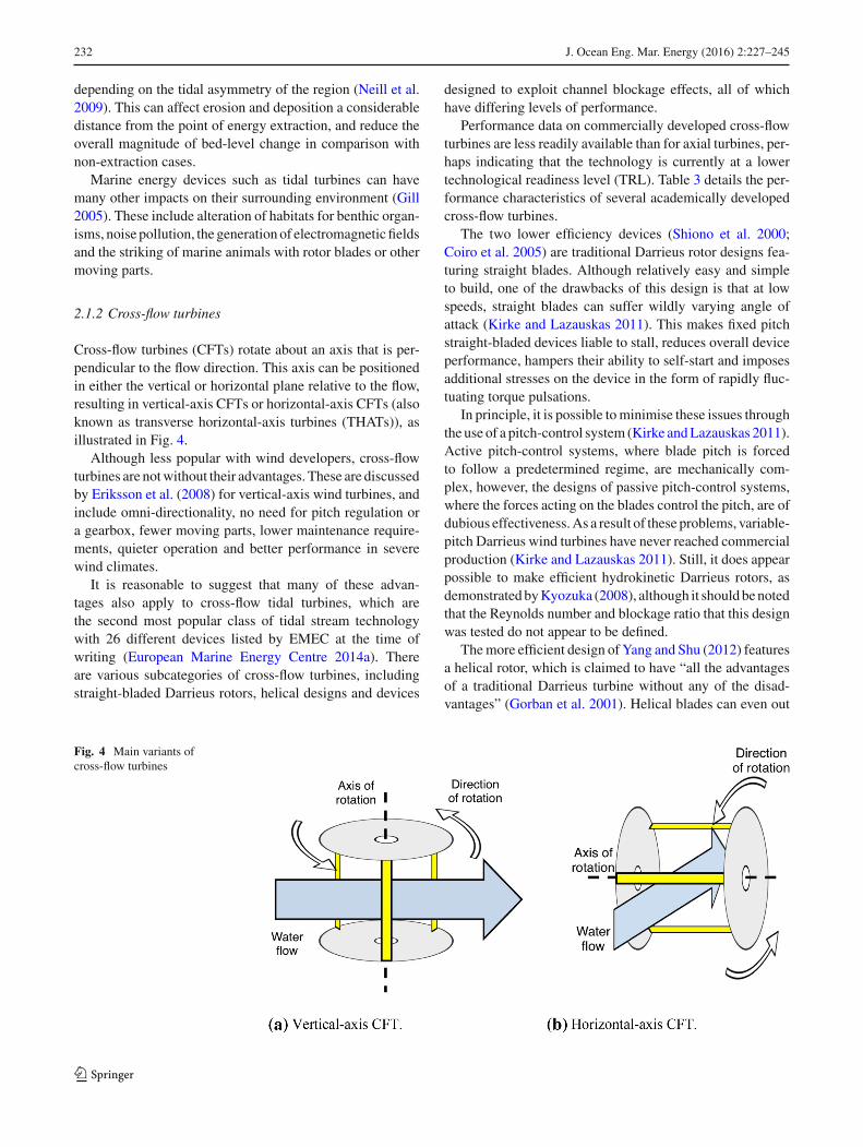
Cross-flow turbines (CFTs) rotate about an axis that is per-pendicular to the flow direction. This axis can be positionedin either the vertical or horizontal plane relative to the flow,resulting in vertical-axis CFTs or horizontal-axis CFTs (alsoknown as transverse horizontal-axis turbines (THATs)), asillustrated in Fig. 4.
Although less popular with wind developers, cross-flowturbines are notwithout their advantages. These are discussedby Eriksson et al. (2008) for vertical-axis wind turbines, andinclude omni-directionality, no need for pitch regulation ora gearbox, fewer moving parts, lower maintenance require-ments, quieter operation and better performance in severewind climates.
It is reasonable to suggest that many of these advan-tages also apply to cross-flow tidal turbines, which arethe second most popular class of tidal stream technologywith 26 different devices listed by EMEC at the time ofwriting (European Marine Energy Centre 2014a). Thereare various subcategories of cross-flow turbines, includingstraight-bladed Darrieus rotors, helical designs and devices
designed to exploit channel blockage effects, all of whichhave differing levels of performance.
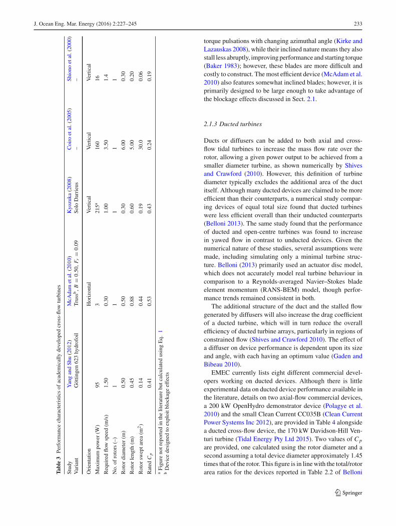
Performance data on commercially developed cross-flowturbines are less readily available than for axial turbines, per-haps indicating that the technology is currently at a lowertechnological readiness level (TRL). Table 3 details the per-formance characteristics of several academically developedcross-flow turbines.
The two lower efficiency devices (Shiono et al. 2000;Coiro et al. 2005) are traditional Darrieus rotor designs fea-turing straight blades. Although relatively easy and simpleto build, one of the drawbacks of this design is that at lowspeeds, straight blades can suffer wildly varying angle ofattack (Kirke and Lazauskas 2011). This makes fixed pitchstraight-bladed devices liable to stall, reduces overall deviceperformance, hampers their ability to self-start and imposesadditional stresses on the device in the form of rapidly fluc-tuating torque pulsations.
In principle, it is possible tominimise these issues throughthe use of a pitch-control system (Kirke andLazauskas 2011).Active pitch-control systems, where blade pitch is forcedto follow a predetermined regime, are mechanically com-plex, however, the designs of passive pitch-control systems,where the forces acting on the blades control the pitch, are ofdubious effectiveness.As a result of these problems, variable-pitch Darrieus wind turbines have never reached commercialproduction (Kirke and Lazauskas 2011). Still, it does appearpossible to make efficient hydrokinetic Darrieus rotors, asdemonstratedbyKyozuka (2008), although it shouldbenotedthat the Reynolds number and blockage ratio that this designwas tested do not appear to be defined.
Themore efficient design of Yang and Shu (2012) featuresa helical rotor, which is claimed to have “all the advantagesof a traditional Darrieus turbine without any of the disad-vantages” (Gorban et al. 2001). Helical blades can even out
Fig. 4 Main variants ofcross-flow turbines
123
J. Ocean Eng. Mar. Energy (2016) 2:227–245 233
Table3
Performance
characteristicsof
academ
ically
developedcross-flo
wturbines
Study
YangandSh
u(2012)
McA
dam
etal.(2010)
Kyozuka
(2008)
Coiro
etal.(2005)
Shiono
etal.(2000)
Variant
Göttin
gen623hydrofoil
Truss
b,B
=0.50
,F r
=0.09
Solo
Darrieus
––
Orientatio
nHorizon
tal
Vertic
alVertic
alVertic
al
Maxim
umpower
(W)
953
215a
160
16
Requiredflo
wspeed(m
/s)
1.50
0.30
1.00
3.50
1.4
No.
ofrotors(–)
11
11
1
Rotor
diam
eter
(m)
0.50
0.50
0.30
6.00
0.30
Rotor
length
(m)
0.45
0.88
0.60
5.00
0.20
Rotor
sweptarea(m
2)
0.14
0.44
0.19
30.0
0.06
Rated
Cp
0.41
0.53
0.43
0.24
0.19
aFigure
notreportedin
theliteraturebutcalculatedusingEq.
1bDevicedesigned
toexploitb
lockageeffects
torque pulsations with changing azimuthal angle (Kirke andLazauskas 2008), while their inclined nature means they alsostall less abruptly, improvingperformance and starting torque(Baker 1983); however, these blades are more difficult andcostly to construct. The most efficient device (McAdam et al.2010) also features somewhat inclined blades; however, it isprimarily designed to be large enough to take advantage ofthe blockage effects discussed in Sect. 2.1.
2.1.3 Ducted turbines
Ducts or diffusers can be added to both axial and cross-flow tidal turbines to increase the mass flow rate over therotor, allowing a given power output to be achieved from asmaller diameter turbine, as shown numerically by Shivesand Crawford (2010). However, this definition of turbinediameter typically excludes the additional area of the ductitself. Although many ducted devices are claimed to be moreefficient than their counterparts, a numerical study compar-ing devices of equal total size found that ducted turbineswere less efficient overall than their unducted counterparts(Belloni 2013). The same study found that the performanceof ducted and open-centre turbines was found to increasein yawed flow in contrast to unducted devices. Given thenumerical nature of these studies, several assumptions weremade, including simulating only a minimal turbine struc-ture. Belloni (2013) primarily used an actuator disc model,which does not accurately model real turbine behaviour incomparison to a Reynolds-averaged Navier–Stokes bladeelement momentum (RANS-BEM) model, though perfor-mance trends remained consistent in both.
The additional structure of the duct and the stalled flowgenerated by diffusers will also increase the drag coefficientof a ducted turbine, which will in turn reduce the overallefficiency of ducted turbine arrays, particularly in regions ofconstrained flow (Shives and Crawford 2010). The effect ofa diffuser on device performance is dependent upon its sizeand angle, with each having an optimum value (Gaden andBibeau 2010).
EMEC currently lists eight different commercial devel-opers working on ducted devices. Although there is littleexperimental data on ducted device performance available inthe literature, details on two axial-flow commercial devices,a 200 kW OpenHydro demonstrator device (Polagye et al.2010) and the small Clean Current CC035B (Clean CurrentPower Systems Inc 2012), are provided in Table 4 alongsidea ducted cross-flow device, the 170 kW Davidson-Hill Ven-turi turbine (Tidal Energy Pty Ltd 2015). Two values of Cp
are provided, one calculated using the rotor diameter and asecond assuming a total device diameter approximately 1.45times that of the rotor. This figure is in linewith the total/rotorarea ratios for the devices reported in Table 2.2 of Belloni
123

234 J. Ocean Eng. Mar. Energy (2016) 2:227–245
Table 4 Performancecharacteristics of selectedcommercial ducted turbines
Developer Clean current Tidal Energy Pty Ltd OpenHydroDevice CC035B DHV 170 kW 200 kW demonstrator
Rated power (W) 6.5 × 10⁴ 1.70 × 10⁵ 2.0 × 10⁵
Rated flow speed (m/s) 3.00 3.00 2.50
No. of rotors (–) 1 1 1
Rotor diameter (m) 3.50 5 10.0
Rotor swept area (m2) 10.0 19.6 79.0
Rotor Cp 0.49 0.63 0.32
Assumed total device area (m2) 20.0 41.2 158
Total device Cp 0.23 0.29 0.16
Fig. 5 Oscillating hydrofoil. Adapted from University of Strathclyde(2006)
(2013); however, this value can andwill vary depending upondevice design. It can be seen that the device Cp values dropsignificantly if the additional area of a duct is considered.
2.2 Oscillating hydrofoils
Anoscillating hydrofoil consists of a hydrofoil wing attachedto a lever arm, as shown in Fig. 5. As a tidal current flows overthe hydrofoil it generates lift, causing the lever to rise. At thepeak of the rise the hydrofoil’s angle of attack changes so thatlift is generated on the underside, reversing the direction ofmotion. The resulting oscillations can be used to drive fluidsin a hydraulic system to power a generator.
With this range of motion, the blades of an oscillatinghydrofoil require a simpler geometry than those of an axialturbine. This is because the flow speed, and therefore angleof attack, over the blades will be the same along their entirelength, meaning they do not require twisting like axial-flowturbine blades do. Consequently they are likely to be easierand cheaper to produce.
An oscillating hydrofoil extracts energy from the tidal cur-rent in a similar manner to a turbine (Kinsey et al. 2011). Theonly difference is the definition of swept area, which for ahydrofoil is the product of the extent of the vertical motionand the wingspan:
P = 1
2ρu3∞bdCp. (5)
Since A = bd, power density is, therefore, the same as Eq.2:
Pd = P
A= 1
2ρCpu
3∞. (6)
Rourke et al. (2010b) mention that oscillating hydrofoilefficiency can be poor due to the time required to reversethe direction of oscillation; the Stingray device described inTable 5 was shelved due to poor performance. Pulse Tidal(2014) are currently developing another commercial oscil-lating hydrofoil device, although there appears to be littlepublished performance data available at the time of writing.It is, therefore, difficult to draw any firm conclusions on theefficiency and power output of oscillating hydrofoils, as thereis a lack of information available.
2.3 Tidal kites
A tidal kite consists of a relatively small turbine attached toa hydrofoil wing, with the entire arrangement tethered to theseabed. Themotion of the tidal currents over the wing createsa lift force that pushes the kite forwards through the water.Through a combination of the tension in the tether and theuse of a rudder, the tidal kite can be directed to “fly” alonga given trajectory through the water column, as illustratedfor the figure-of-eight trajectory of the Minesto Deep Greentidal kite in Fig. 6.
This movement increases the speed of the flow passingthrough an axial-flow turbine, allowing greater amounts ofpower to be generated from lower free-stream speeds using
123

J. Ocean Eng. Mar. Energy (2016) 2:227–245 235
Table 5 Performancecharacteristics of oscillatinghydrofoils
Device source Kinsey et al. (2011) Stingray (The Engineer-ing Business Ltd 2003,2005)
Maximum power (W) 2.00 × 10³ 8.53 × 10³a
Required flow speed (m/s) 1.99 2.00
Blade span (m) 1.68 15.5
Extent of vertical motion (m) 0.61 12.6b
Swept area (m2) 1.02 195
Power density (W/m2) 1.96 × 10³ 43.7
Rated Cp 0.40 0.12
a Mean hydraulic power produced over 30-min operating period (The Engineering Business Ltd 2005)b Calculated from arm length and operating angle reported in The Engineering Business Ltd (2003)
Fig. 6 Operatingmethod and schematic ofMinesto’s DeepGreen tidalkite. Adapted from Minesto (2013)
a smaller turbine. The mechanical energy of the turbine isconverted to electrical energy using a direct-drive generatorattached to the kite, which is then transmitted through a cablein the tether to the seabed and then to the shore via a subseacable. Table 6 summarises the specifications of several DeepGreen devices.
The power coefficient estimates were calculated using Eq.1, the rotor diameters and Minesto’s claim that the devicemoves at a speed 10 times greater than the water current. Forthe calculated power densities, total device swept area was
estimated as a semi-circle with the minimum tether length asits radius, resulting in the very low values shown. In practice,the swept area is likely to be much smaller than this. In waterdepths appropriate for the technology, tidal kites certainlyappear capable of producing great amounts of power for thesize of their rotors.
2.4 Tidal range
Tidal range devices make use of the difference in water levelbetween high and low tide by impounding water within abasin before releasing it across turbines, as illustrated inFig. 7. By closing sluice gates, water is trapped on one sideof the device, creating a static head across it due to the move-ment of the tides. When the head is suitably large, the gatesare opened and the excess water is directed across turbinesfor electricity generation.
Tidal range devices can use various generation schemes:ebb generation, flood generation and two-way generation(Xia et al. 2010a). These different schemes allow some flexi-bility in how the plant operates, depending upon the strengthof the tide and grid requirements (Frau 1993).
• Ebb generation: power is generated when the flow isdischarged across the turbines in the direction of the out-going ebb tide, i.e. from the basin towards the sea. Afull ebb generation cycle consists of four stages—filling,holding, generating and holding once again.
• Flood generation: essentially the mirror image of ebbgeneration, though generally less efficient due to theshape of the seabed. Since the volume of water in theupper half of the basin (utilised first by ebb generation)is greater than the volume in the lower half (filled firstduringflood generation), thewater level difference acrossthe barrage reduces more quickly.
• Two-way generation: an amalgamation of both ebb andflood schemes. Consequently the tidal range within the
123

236 J. Ocean Eng. Mar. Energy (2016) 2:227–245
Table 6 Minesto Deep Greenspecifications
Device DG-8 DG-10 DG-12 DG-14
Rated power (W) 1.10 × 10⁵ 2.20 × 10⁵ 5.00 × 10⁵ 8.50 × 10⁵
Rated speed (m/s) 1.30 1.40 1.60 1.73
Rotor diameter (m) 0.67 0.83 1.00 1.15
Tether length (m) 60–80 75–100 85–120 110–140
Installation depth (m) 50–65 60–80 75–100 90–120
Wing span (m) 8.00 10.0 12.0 14.0
Weight (tonnes) 2 4 7 11
Devices/km2 (–) 50 30 25 16
Power/m2 (W/ m2) 5.50 6.60 12.5 13.6
Estimated swept area (m2) 5.70 × 10³ 8.84 × 10³ 1.14 × 10⁴ 1.90 × 10⁴
Estimated Pd (W/m2) 19 24 44 45
Estimated rotor Cp (–) 0.28 0.29 0.30 0.31
Sourced from Minesto (2014)
Fig. 7 Tidal barrage operation. Adapted from Wyre Tidal Energy(2014)
basin is closer to its natural range, which is thought toreduce environmental impacts in comparison to one-waygeneration.
By considering the volume of water impounded within thebasin, a crude estimate of the potential energy (and subse-quently power) available from a tidal range device can beobtained as follows (Lamb 1994):
Ep = 1
2AbρgH
2. (7)
The factor of 1/2 arises due to the assumption of a linearreduction in hydraulic head as the basin empties (i.e. overhalf the tidal cycle). For a device utilising an ebb generationscheme, the average daily power generated by a range deviceis simply:
P = Ep
tε = AbρgH2
2tε (8)
where t is the length of the tidal period in seconds. The powerdensity in terms of power per unit of basin area can then becalculated as:
Pd = P
Ab= ρgH2
2tε. (9)
Themaximumpower density values for four theoretical rangeschemes of different efficiencies, calculated using Eq. 9, areshown in Fig. 8 for tidal ranges between 0 and 20 m.
It can be seen from this simple analysis that barrages andlagoon devices only produce a small amount of power fortheir surface area. For the maximum calculated 20 m tidalrange, the available power density for a 100% efficient rangedevice is approximately 45 W/m2, while for the 16 m tidalrange found in Canada’s Bay of Fundy [which has the highesttides in the world (Archer and Hubbard 2003)] the powerdensity is approximately 30 W/m2.
There are relatively few locations in the world that havetidal ranges approaching this value, however, meaning rangedevices are unlikely to reach this figure in all but a handful ofplaces. Tidal range projects are also typically characterisedby low values of ε (Xia et al. 2012), with values typicallyranging from 20 to 40 % and an average of 33 % often usedin theoretical energyoutput estimations.At these efficiencies,the power density of a range scheme is clearly going to belower.
123

J. Ocean Eng. Mar. Energy (2016) 2:227–245 237
Fig. 8 Theoretical powerdensity for a barrage or lagoonfor tidal ranges of 0–20 m
0 2 4 6 8 10 12 14 16 18 200
5
10
15
20
25
30
35
40
45
50
Tidal range (m)
Pow
erde
nsity
(W/m
2 )
Efficiency = 1.00Efficiency = 0.40Efficiency = 0.33Efficiency = 0.20
εεεε
Table 7 Current operational barrages
Barrage Inauguration date Mean tidal range (m) Basin area (km2) Capacity (MW) Source
La Rance, France 1966 7.9 43 240 Frau (1993)
Sihwa Lake, South Korea 2011 7.8 23 254 Kim et al. (2012)
Annapolis Royal, Canada 1985 6.4 6 20 Frau (1993)
Jiangxia, China 1980/1986 5.0 2 3.2 Frau (1993)
Kislaya Guba, Russia 1968 2.4 2 0.4 Frau (1993)
As stated above, however, the values provided by Eqs. 7–9are only a crude estimate. For a specific location, integratingover the tidal curve, rather than averaging, will provide amore realistic estimate of power. Given that the shape of thebasin and turbine positioning can also affect range schemeperformance, numerical models, such as those of Xia et al.(2010b) provide an even more accurate method of assessingpotential power output. It is also worthwhile to consider thepower output of currently operational tidal range devices,which are presented in Table 7.
The economics of a range scheme scale according to theamount of water in a basin between mean high and low tide,which is known as the volume of the tidal prism (Frid et al.2012). As a result, optimal tidal range structures are situatedin estuaries with high tidal ranges, and feature large basinsfor water impoundment (Kadiri et al. 2012).
A particular advantage of tidal range structures is theirvery long lifespans; for example, the design lifetime of theproposed Severn Barrage is 120 years, with turbine replace-ment occurring every 40 years (Kelly et al. 2012). Rangestructures have such long operational lifetimes due to thefact that the turbines are enclosed within a sturdy concretestructure and are consequently less exposed to the marineenvironment, with relatively easy access provided for main-tenance work.
2.4.1 Tidal barrages
Tidal barrages are long structures built across bays or estu-aries, making use of the surrounding land to create a basin inwhich water can be impounded.
Barrages are mature and reliable; however, they do comewith significant capital and environmental costs that can bedifficult to overcome (Blunden and Bahaj 2006). This is evi-denced by the fact that there are only five tidal barragescurrently in operation globally, despite there being severalsites across the world considered suitable for development(Charlier 2007)
The largest example of a barrage is the Sihwa Lake TidalPower Station in South Korea, which is rated at 254 MWand makes use of a seawall that was originally constructed in1994 for flood defence (Bae et al. 2010). A list of operationtidal barrages, such as the Rance River Barrage shown inFig. 9, provided in Table 7.
In regions of high tidal range, such as the Severn Estuaryin the UK, large-scale range schemes would be capable ofproducing colossal amounts of power. For example, the pro-posed Cardiff–Weston barrage in the Severn Estuary, UK,would have an installed capacity of 8.64 GW and provide anestimated 17 TWh of electrical energy per year (Xia et al.2010a). This power capacity is significantly greater than the
123

238 J. Ocean Eng. Mar. Energy (2016) 2:227–245
Fig. 9 The Rance River Barrage, Brittany, France. Sourced fromwikipedia.org (2015)
maximum of 154 MW predicted by Ahmadian and Falconer(2012) for tidal stream turbine arrays in that location. Indeed,the predicted 17 TWh of energy per year is greater even thanthe estimated 12.7 TWh/year resource available in the entirePentland Firth, arguably the UK’s top site for tidal streampower (Sustainable Development Commision 2007).
Such schemes can also have significant environmentalimpacts, both positive and negative. For example, Kirby andShaw (2005) argue that a Severn barrage would reduce thestrength of the tidal currents and thus reduce the suspendedsediment load while providing greater bed stability, encour-aging the colonisation of an otherwise highly suppressedecosystem. Through a numerical study, Ahmadian et al.(2010) confirmed that suspended sediment levels in peakspring tide conditions would reduce from 1200 to 200 mg/lupstream of a Severn barrage. More generally, the change insuspended sediment loads is related to the local geology ofthe estuary bed (Xia et al. 2010b); consequently it is difficultto say whether this reduction would occur in all locations.Barrages and lagoons are also likely to increase sedimentdeposition in certain areas, the location and magnitude ofwhich will depend upon specific design and the prevailingsource of the sediment (Kadiri et al. 2012).
Tidal barrages have also been found to impact on sur-rounding water levels. For example, Xia et al. (2010c)predicted that maximum water levels upstream of a Severnbarrage would decrease by 0.5–1.5 m, reducing the risk offlooding along the estuary. Barrages, therefore, have addi-tional use as flood defences, particularly in the context ofclimate change and rising sea levels (Ahmadian et al. 2014).This may be a huge benefit for certain locations, given thatit will also prevent the need to spend money on conventionalflood defences (Department of Energy and Climate Change2010). In a similar vein they may also be used as bridgesacross bodies of water, leading to regeneration opportuni-ties, as is the case at La Rance in France.
For ebb generation schemes, the reduction of water levelscaused by a barrage also has negative connotations, particu-
larly in terms of habitat loss. For example, Zhou et al. (2014)predicted through numerical modelling that the siting of anebb-only barrage across the Severn Estuary between CardiffandWeston-Super-Mare would result in the loss of 80.5 km2
of intertidal habitats. Zhou et al. (2014) also predicted thatsalinity levels would be reduced by up to 5 parts per thou-sand at high water upstream of the device. This would reducedissolved metal and nutrient concentrations in the water col-umn (Kadiri et al. 2012), and would also impact on dissolvedoxygen concentrations, again impacting on habitats withinthe area.
Local wave climate may also be affected, for example,(Fairley et al. 2014) found that the construction of a Severnbarrage would increase net downstream wave heights over atidal cycle by almost 20 % compared to pre-barrage condi-tions, which could have implications for coastal erosion andsediment transport.
These impacts on water levels and habitats can be reducedthrough the use of two-way generation, which allows thetidal range of the basin to remain closer to its natural cycle.The impacts may not be completely mitigated however; thenumerical model of Xia et al. (2010c) indicated that waterlevels upstream of a two-way barrage are still reduced, whichwill lead to habitat loss.
Other methods for minimising the environmental impactsof barrages can be seen in the Evans Engineering REEF sys-tem (Evans Engineering and Power Company 2011), whichmaintains a small but constant head difference rather thandelaying the tides to generate a larger head. This is alsothought to reduce the effect on the tidal range of the basin,in turn reducing impacts on intertidal habitats. The proposedscheme also features low-head, low-speed turbines, with asmall number of widely spaced blades, to assist the pas-sage of migratory fish. The two-way Hafren barrage schemefor the Severn Estuary, featuring 1026 Very Low Head bi-directional turbines, has also been proposed as a way ofmitigating impacts on wildlife, with up to 60 % less habi-tat loss in comparison to an ebb-only scheme. However, thecase for the Hafren barrage is currently unproven (House ofCommons Energy 2013). In addition to a failure to demon-strate value for money for consumers, this is still partly dueto environmental concerns. These include the loss of someintertidal habitat due to a reduction in tidal range and apparentcontradictions regarding impacts on flooding. These issueshighlight the lack of empirical data surrounding the environ-mental impacts of tidal power in general, and demonstrate theneed for further research before such impacts can be assessedwith certainty.
2.4.2 Tidal lagoons
A tidal lagoon is similar to a barrage; however, instead ofbuilding a single structure across thewidth of a bay or estuary
123
J. Ocean Eng. Mar. Energy (2016) 2:227–245 239
and using surrounding land to form the basin walls, a tidallagoon consists of an entirely man-made basin with turbinesembedded within the constructed walls. Consequently, sincea larger structure is required to create a basin of comparablearea to that of a barrage, tidal lagoons require higher capitalexpenditure than barrages of comparable power (Baker et al.2006; Entec UK Ltd 2007).
Without blocking off an entire estuary or bay, the impactsof a lagoon on water flow, sediment transport, fish migra-tion and shipping may be comparatively less than those ofbarrages outside the basin area and on the region as a whole(Kadiri et al. 2012). For example, the construction of a tidallagoon on the Welsh coast of the Severn Estuary has beenpredicted to have little impact on the hydrodynamics of theregion overall (Xia et al. 2010b), though the hydrodynam-ics within the lagoon itself can still be changed dramatically.Additionally, impacts in the area immediately surroundinga lagoon, particularly on sediment transport, may be moresignificant than for barrages. For example, the proposedSwansea Bay Tidal Lagoon is predicted to interrupt the trans-port of sand, creating a build-up of material along the outsideof the structure’s eastern wall (Tidal Lagoon Swansea Bayplc 2015). Consequently a monitoring plan is being devel-oped to implement measures such as beach nourishment anddredging where necessary.
In the same region, it has also been predicted that coastallyattached lagoons will cause a smaller reduction on upstreamwater levels in comparison to barrages (Kadiri et al. 2012).While this may be of benefit in terms of minimising habi-tat loss, it also indicates that lagoons are likely to notbe as effective at reducing the risk of flooding. Even so,studies of proposed tidal lagoons off the coast of NorthWales have shown that coastally attached impoundments canoffer some level of reduced flood risk, by reducing peaktidal levels and reducing wave heights (Ahmadian et al.2010).
Inside the basin, sediment deposition is likely to occur, andperiodic dredging may be required to preserve energy yield(Department of Energy and Climate Change 2010). This isdue to the generation of strong recirculating currents withinthe impoundment area as a result of turbines being locatedin only part of the wall, inducing tidal eddies or large vor-tices (Ahmadian et al. 2010). Spreading the turbines aroundthe perimeter of the device, as is done along the length ofbarrages, can reduce the likelihood of such eddies, however,for lagoons this is likely to reduce their commercial viabil-ity.
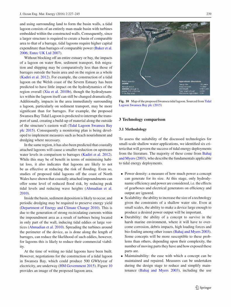
At the time of writing no tidal lagoons have been built.However, negotiations for the construction of a tidal lagoonin Swansea Bay, which could produce 500 GWh/year ofelectricity, are underway (HMGovernment 2015). Figure 10provides an image of the proposed lagoon area.
Fig. 10 Mapof the proposedSwansea tidal lagoon. Sourced fromTidalLagoon Swansea Bay plc (2015)
3 Technology comparison
3.1 Methodology
To assess the suitability of the discussed technologies forsmall-scale shallow water applications, we identified six cri-teria that will govern the success of tidal energy deploymentsfrom the literature. The majority of these come from BahajandMyers (2003), who describe the fundamentals applicableto tidal energy deployments.
• Power density: a measure of how much power a conceptcan generate for its size. At this stage, only hydrody-namic efficiency and power are considered, i.e. the effectsof gearboxes and electrical generators on efficiency andoutput are ignored.
• Scalability: the ability to increase the size of a technologygiven the constraints of a shallow water site. Even atsmall scales, the ability to make a device large enough toproduce a desired power output will be important.
• Durability: the ability of a concept to survive in theharsh marine environment, where it will have to over-come corrosion, debris impacts, high loading forces andbio-fouling among other issues (Bahaj and Myers 2003).Some concepts will be more susceptible to these prob-lems than others, depending upon their complexity, thenumber ofmoving parts they have and how exposed theseparts are.
• Maintainability: the ease with which a concept can bemaintained and repaired. Measures can be undertakenduring the design stage to reduce and simplify main-tenance (Bahaj and Myers 2003), including the use
123
240 J. Ocean Eng. Mar. Energy (2016) 2:227–245
of good-quality lubricants, seals, and strong materials,incorporating all the moving parts of the device into onespecific feature and an ability to raise the device out ofthe water.
• Economic potential: for a concept to be viable it mustgenerate electricity at a competitive cost. However, giventhe many variables involved it is difficult to quantify theeconomic potential of each concept precisely; therefore,a more qualitative assessment based on the complexity,scalability and power density of each device is used.
• Environmental impacts: many coastal regions are eco-logically diverse areas, and are used for a wide numberof commercial and recreational activities. Consequently,it is vital to consider the magnitude of the impacts eachconcept has on its surroundings, given that even relativelysmall interventions can cause significant impacts.
We perform a design-stage examination of the performanceof each tidal technology class by comparing their perfor-mance against that of a reference concept, in this case theaxial-flow tidal stream turbine. Given the site-specific natureof tidal power and the absence of large amounts of data formany of the technologies, we limit our evaluation to dis-cussion only, using the particular benefits and drawbacks ofeach technology to highlight those most suited to small-scaleshallow water generation.
3.2 Technology comparison
3.2.1 Power density
Given the dependence of power output on device efficiencyand site bathymetry, along with either flow speed or tidalrange, it is difficult to directly compare the power density oftechnologies in the absence of specific site data. However,some broad points can be drawn from the data presented inSect. 2.
As shown in Fig. 3, axial-flow turbines are theoreticallycapable of generating over 1 kW/m2 in unbounded flowsgreater than 1.5 m/s, while theoretical cross-flow devicesshould be capable of producing slightly more power for theirsize in those same flows. Given that the reported efficienciesof three of the experimental cross-flow devices presented inTable 3 are similar or greater than those of the axial-flowdevices in Tables 1 and 2, it seems reasonable to suggestthat cross-flow devices can produce more power for theirsize than axial turbines, which will be of benefit in small-scale deployments, particularly in shallow waters. Althoughoscillating hydrofoils may have issues with efficiency if theStingray device is indicative of their performance, the devicetested by Kinsey et al. (2011) suggests their efficiencies canalso be comparable to those of unducted turbines. Thismeans
they should also be capable of producing large amounts ofpower for their size.
Other tidal stream concepts do not appear to compare sofavourably however. Ducted turbines, both axial and crossflow, are capable of producing a given amount of power froma smaller rotor than an unducted device, while the duct alsoassists power generation in yawed flow. Once the extra areaof the duct is taken into account, however, the power pro-duced by the total device is likely to be comparatively lessthan that of an unducted turbine. Tidal kites, which are againcapable of producing great power for the size of their rotors,presently require large installation depths, effectivelymakingthem unfeasible in shallow waters.
The power density of tidal range devices, though appear-ing to be much lower than that of axial-flow turbines, isdefined differently, in that it is the power per unit of basinarea, rather than power per unit of frontal area. Consequently,provided a location has a large enough tidal range to createsufficient head for generation, barrages and lagoons will beperfectly capable of operating in shallow waters. Their lowpower density in terms of surface area does, however, meanthat their basins will likely need to be at least hundreds ofsquare metres to generate comparable levels of power. Thiswould somewhat defeat the purpose of a small-scale device,since the amount of investment andmaterials required to cre-ate such a basin, particularly for a lagoon,will be significantlyhigher than that required to install a turbine of similar output(assuming the resources are there for both technologies).
3.2.2 Scalability
In shallowwaters, the maximum size of an axial-flow turbinewill be constrained by water depth due to the circular sweptarea of its rotor, which would limit maximum power out-put. For both vertical and horizontal-axis cross-flow turbines,however, size would not be limited due to their rectangu-lar area; consequently they could be scaled up to reach aspecified output. Oscillating hydrofoils also benefit from arectangular swept area, and consequently could be scaledaccording to a specific demand as well.
For a ducted device, the extra space required by the ductitself would limit the overall scalability in comparison to anunducted turbine. Tidal kites would be even more limited inshallow waters, given that they require long tether lengths sothey can sail through their figure-of-eight motion.
Given that their power output is dependant on the differ-ence inwater level between high and low tide but independentof actual water depth, the maximum size of a tidal rangedevice would not be constrained by water depth. While abarrage would require a natural basin, such as a bay or estu-ary, to serve as an impoundment area, in theory lagoons canbe constructed on or off any open coastline with a tidal rangelarge enough to provide a sufficient head. This would be a
123

J. Ocean Eng. Mar. Energy (2016) 2:227–245 241
definite advantage, in terms of reaching a desired power out-put.
3.2.3 Durability
Axial-flow turbinesThe rotor blades of unducted axial-flow turbines are com-
pletely exposed to the marine environment, making themsusceptible to damage and bio-fouling, which would be anissue in shallow waters due to the proximity of the photiczone. To produce power from both flood and ebb tides, axial-flow turbines also require some sort of yawing mechanismto ensure they are facing the prevailing current direction.
Vertical cross-flow turbines are omni-directional whilehorizontal designs are bi-directional, negating the need foryawing mechanisms and so reducing complexity in compar-ison to axial turbines. Blade tips will also be less exposedthan those of an axial turbine, although the blades will besusceptible to damage and bio-fouling. Torque pulsation canbe an issue for straight-bladed Darrieus rotor designs, whichrequire pitch-control mechanisms to limit the blade angle ofattack and minimise stalling at low speeds. The use of heli-cal blades can also prevent this problem, however, withoutincreasing mechanical complexity.
A duct would provide some protection for the blades ofboth axial and cross-flow turbines against debris and bio-fouling, while the need for a smaller rotor to produce a givenamount of power would also help improve durability. In con-trast, the fully exposed blades of an oscillating hydrofoil arelikely to suffer similar effects as those of unducted axial-flow turbines. Given their oscillatory motion, fatigue mayalso be more of an issue for hydrofoils than it is for axial-flow turbines, and such problems would be exacerbated withincreasing blade length. The additional complexity of multi-ple moving parts means tidal kites may also suffer in termsof durability.
Both barrages and lagoonswill bemuchmore durable thanaxial-flow turbines, given that their turbines are less exposedto the marine environment. This can be seen in a comparisonof the lifespans of the structures: while the MCT SeaGen hasa design life of 20 years, a proposed Severn Barrage has adesign life of 120 years (with the turbines themselves needingreplacing at 40-year intervals).
3.2.4 Maintainability
Maintenance of axial-flow turbines would be challenging,since all moving parts, including the generator, tend to belocated underwater. This can be overcome in design, throughthe use of stronger materials, a geared transmission systemto position the generator above the surface and lifting rotorssuch as those on the MCT SeaGen device.
A vertically oriented cross-flow device would permit thegenerator to be located above the water line without the needfor anything more complex than a drive shaft, which wouldpermit easier maintenance. Axial-flow turbines and horizon-tal CFTs require a more complex transmission system toachieve this; however, it is eminently possible through theuse of gearing or universal joints. In all cases, however, main-tenance of the turbine itself will be challenging, given that itis located underwater. For ducted turbines this will be com-plicated further due to the duct potentially restricting accessto certain parts, otherwise their maintenance needs would bebroadly similar to those of unducted turbines.
The maintenance needs of oscillating hydrofoils will bedifferent to those of turbines, given that they have a differ-ent power take off mechanism. The presence of additionalhydraulic fluids underwater and the potential for leaks intothe environment may make maintenance more difficult. Aswith turbines, however, the generator itself could be locatedabove the surface for easy access. Meanwhile tidal kiteswould be relatively easy to maintain in comparison to tur-bines, since the kite itself can be detached from the tetherand floated to the surface for repair work.
The turbines of a barrage or lagoon would be relativelyeasy to reach for maintenance work, however, depending onthe site and generation scheme employed, dredging of thebasin may be required to counter sedimentation and preserveenergy yield.
3.2.5 Economic potential
Despite producing good amounts of power for the size oftheir rotors, the limitations on themaximumsize of axial-flowturbines in shallow waters may hamper economic potential.In contrast, the power density and scalability of cross-flowturbines would suggest than an efficient design of either ver-tical or horizontal orientation is likely to have good economicpotential. Ducted turbines, due to their more limited scalabil-ity and lower total power density, are likely to generate lesspower over the course of their lifespans, and therefore lessof a return on investment.
Given their scalability in shallowwaters, an efficient oscil-lating hydrofoil device is also likely to have good economicpotential, comparable to that of a cross-flow turbine. Tidalkites, however, given their apparent requirement for deepwaters, would not be capable of generating as much electric-ity, and consequently their economic potential is likely to belower.
The comparatively large amount of materials and con-struction work required to construct a barrage, which bydefinition is even greater for a lagoon, means that the initialcapital required for a range scheme will likely be signifi-cantly higher than it is for a tidal stream device. If a givenamount of electricity is to be generated, this would signifi-
123
242 J. Ocean Eng. Mar. Energy (2016) 2:227–245
cantly hamper the economic potential of a range scheme incomparison, at least at small scales. The longer lifespan ofrange devices (120 years with turbine replacement occurringevery 40 years, in comparison to the 20 years for the MCTSeaGen)would go towardsmitigating this, however.Whetherit does so completely would depend upon the specifics of aproject.
3.2.6 Environmental impacts
Given the similarities in how they extract energy from theflow, the environmental impacts of axial-flow and cross-flowturbines of both orientations are likely to be broadly the same.As discussed in Sect. 2.1.1, these will include impacts onwater quality, such as reducing upstream and downstreamflow speeds, potentially affecting sediment transport, andalso accelerating the flow immediately around the device,potentially leading to scouring. Other risks include alteringthe habitats of benthic organisms, noise pollution, the gen-eration of electromagnetic fields and the striking of marineanimals with rotor blades or other moving parts. For ducteddevices, it is possible that the higher drag coefficient causedby the extra structure of the duct may result in greaterimpacts on water quality, given that it has a greater impacton basin efficiency. The magnitude of the environmentalimpacts of an oscillating hydrofoil will likely be similarto those as well, though the potential for hydraulic fluidsto leak into the environment will perhaps be a greater con-cern.
The small turbines of tidal kites would produce smallwakes located higher in the water column, while the lack ofa large superstructure would likely reduce scouring effectson the seabed compared with conventional axial-flow tur-bines. Depending on the range and speed ofmotion, however,tidal kites could present a greater danger of colliding withmarine animals in comparison with static technologies. Thismay also result in a need for slightly larger exclusion zonesaround the device, to prevent collisions with marine traf-fic.
As discussed in Sect. 2.4, the environmental impacts oftidal range schemes can be positive as well as negative.For example, barrages may have uses in certain areas asflood defence schemes; however, changes in water level canadversely affect intertidal habitats, while the presence oflarge offshore structures also impacts sediment transport andthe routes of migratory fish. From the literature, the regionalimpacts of barrages tend to be more significant than those oflagoons; however, lagoons may suffer more with recircula-tion currents within their basins due to their shape. Lagoonsmay also havemore significant environmental impacts on thearea directly surrounding them, particularly with regards tosediment transport and deposition. These impacts all tend tobe proportional to the size of the scheme, and consequently
will be significantly reduced at smaller scales. The gener-ation scheme used, either ebb, flood, or two way, will alsoimpact upon their magnitude; however, further research isrequired for these differences in impact to be assessed withcertainty, due to a lack of empirical data. This is equally trueof all tidal technologies.
3.2.7 Overall suitability
From the above discussion, tidal kites do not appear suitablefor use in shallow water areas simply because they requiredeep waters to function correctly. Barrages and lagoonsalso appear unsuitable for small-scale generation, since theywould require greater financial and material investment toinstall in comparison to a tidal stream device. Of the two,a lagoon would suffer more in terms of investment, whilea barrage is likely to have greater impacts on the regionalenvironment.
Ducted turbines do not appear as well suited as othertechnologies either. While their rotors have higher powerdensities than those of axial turbines, the additional arearequired for the duct means the total device power density islikely to be lower in practice. This additional structure alsoimpedes the overall scalability of a device, which combinedwith lower overall power density would hamper economicpotential. Axial-flow turbines also do not appear to be as suit-able as some other technologies. Although they have higherpower densities than the majority of the other concepts, theirsize is completely limited bydepth, limiting the overall poweroutput of a single device.
Oscillating hydrofoils have been described as being suit-able for shallow water use (Kinsey et al. 2011; Pulse Tidal2014), and certainly appear more suitable for shallow waterapplications than axial turbines. Although the mothballedStingray device struggled with poor efficiency, the devicetested by Kinsey et al. (2011) has a comparable efficiencyto unducted turbines. This combined with their rectangu-lar swept area means overall power output would not beconstrained by depth, giving them good economic poten-tial.
Both vertically and horizontally oriented cross-flow tur-bines appear to be very suitable for shallow water appli-cations, due to their scalability and relatively high powerdensities. This means they should have greater generat-ing capacity in shallow waters compared with axial-flowturbines, and consequently good economic potential. Avertical-axis configuration would be capable of operating inany flow direction, while the bi-directionality of a horizon-tally configured device would cope with ebb and spring tidalflows without the need for a yawing mechanism. The use ofhelical blades would also prevent the need for mechanicallycomplex pitch-control systems.
123
J. Ocean Eng. Mar. Energy (2016) 2:227–245 243
4 Conclusions
The suitability of eight different tidal power technologies forsmall-scale power generation in shallow near-shore watersoff have been discussed by examining device performancesin a number of key criteria. Our discussion suggests thatboth vertically and horizontally oriented cross-flow turbinesappear to be well suited to this application, since they haverelatively high power densities and a maximum device sizethat is unconstrained by depth. Oscillating hydrofoils alsoappear suitable to shallow water applications for similarreasons, provided comparable levels of efficiency can bereached. Meanwhile tidal kites, which require deep waters,and tidal barrages and lagoons, which will require signif-icantly more investment to generate comparable levels ofpower at small-scale in comparison to turbines, appear to bethe least appropriate for this scenario.
It is important to note that this examination is a simpledesign-stage assessment. Due to the developing nature ofthe tidal energy sector, several of the assessment criteria(e.g. environmental impacts, economic potential) are qual-itative in nature and have been discussed in the absenceof large amounts of reliable data. Additionally, given theinfluence various device-specific factors (e.g. hydrofoil bladeprofile) may have on device performance, certain commentsmay not apply to every device within a given technologyclass.
Although we have provided a general technology reviewfor one type of tidal energy deployment in the absence oflarge amounts of field data, for a given project at a spe-cific site there will be further complicating factors that willaffect the performance of a given technology (e.g. block-age). The influences of these factors on performance mayvary even throughout the site itself, and consequently asmuch data on the site as possible should be gathered beforeattempting to identify the most appropriate technology forthat area.
Despite the eight discussed concepts appearing to com-prise the bulk of tidal technology currently in development,there are also other devices used formicro hydropower appli-cations, such as Archimedes screws and gravitational watervortices, which have not been investigated and could be suit-able for use in shallow water tidal applications. Furthermore,it is possible that with suitable adaptation the ideas behindsome of the concepts (the tidal kite for instance) could provevery effective for shallow water generation, while there isalso scope that completely novel ideas could also be suitable.Consequently this discussion is by no means exhaustive ordefinitive. Future work will look to explore the possibilitiesof adapting both the discussed technologies and others todevelop an optimised device for shallow water tidal powerapplications.
Acknowledgments The authors would like to thank BournemouthUniversity and the Balmain Environmental Trust for funding the projectthat this review is part of.
OpenAccess This article is distributed under the terms of theCreativeCommons Attribution 4.0 International License (http://creativecommons.org/licenses/by/4.0/), which permits unrestricted use, distribution,and reproduction in any medium, provided you give appropriate creditto the original author(s) and the source, provide a link to the CreativeCommons license, and indicate if changes were made.
References
Ahmadian R, Falconer RA (2012) Assessment of array shape of tidalstream turbines onhydro-environmental impacts andpower output.Renew Energy 44:318–327
AhmadianR, FalconerRA,Bockelmann-EvansB (2012) Far-fieldmod-elling of the hydro-environmental impact of tidal stream turbines.Renew Energy 38(1):106–116
Ahmadian R, Falconer RA, Lin B (2010) Hydro-environmental mod-elling of proposed Severn barrage, UK. Proc ICEEnergy 163:107–117
Ahmadian R, Morris C, Falconer RA (2010) Hydro-environmentalmodelling of off-shore and coastally attached impoundments ofthe North Wales Coast. In: The First IAHR European Congress,Edinburgh
Ahmadian R, Olbert AI, Hartnett M, Falconer RA (2014) Sea level risein the Severn Estuary and Bristol Channel and impacts of a SevernBarrage. Comput Geosci 66:94–105
Archer AW, Hubbard MS (2003) Highest tides of the world. In: ChanMA, Archer AW (eds) Extreme depositional environments: megaend members in Geologic Time. Geological Society of AmericaSpecial Paper 370, chap 9, pp 151–174
Bae YH, Kim KO, Choi BH (2010) Lake Sihwa tidal power plantproject. Ocean Eng 37(5–6):454–463
Bahaj AS (2011) Generating electricity from the oceans. Renew SustainEnergy Rev 5(7):3399–3416
Bahaj AS, Molland AF, Chaplin JR, Batten WMJ (2008) Power andthrust measurements of marine current turbines under varioushydrodynamic flow conditions in a cavitation tunnel and towingtank. Renew Energy 32(3):407–426
Bahaj AS, Myers LE (2003) Fundamentals applicable to the utilisationof marine current turbines for energy production. Renew Energy28:2205–2211
Baker JR (1983) Features to aid or enable self-starting of fixed pitchlow solidity vertical axis wind turbines. J Wind Eng Ind Aerodyn15(1–3):369–390
Baker C, Walbancke J, Leache P (2006) Tidal lagoon power generationscheme in Swansea Bay.WelshDevelopment Agency, Departmentof Trade and Industry. http://www.bright-sparks.biz/wp-content/uploads/2015/12/DTI-paper-on-Swansea-Bay-lagoon-scheme.pdf
BattenWMJ, Bahaj AS, Molland AF, Chaplin JR (2006) Hydrodynam-ics of marine current turbines. Renew Energy 31(2):249–256
Belloni C (2013) Hydrodynamics of ducted and open-centre tidal tur-bines PhD Thesis. University of Oxford
Betz A (1966) Introduction to the theory of flow machines. PergamonPress, New York
Blunden LS, Bahaj AS (2006) Initial evaluation of tidal stream energyresources at Portland Bill. UK. Renew Energy 31(2):121–132
Bourne Energy (2014) Energy for the future. http://www.bourneenergy.com/future.html. Accessed 8 Apr 2014
123

244 J. Ocean Eng. Mar. Energy (2016) 2:227–245
Bryden IG, Couch SJ, Owen A, Melville G (2007) Tidal currentresource assessment. Proc Inst Mech Eng Part A J Power Energy212(2):125–135
Bryden IG, Naik S, Fraenkel PL, Bullen CR (1998) Matching tidalcurrent plants to local flow conditions. Energy 23(9):699–709
Charlier RH (2007) Forty candles for the Rance River TPP tides pro-vide renewableand sustainable power generation. Renew SustainEnergy Rev 11(9):2032–2057
Clean Current Power Systems Inc (2012) Clean current–tidal in-streamturbines [Online]
Coiro DP, De Marco A, Nicolosi F, Melone S, Montella F (2005)Dynamic behaviour of the patented kobold tidal current turbine:numerical and experimental aspects. Acta Polytech 45(3):77–84
Coiro DP, Maisto U, Scherillo F, Melone S, Grasso F (2006) Horizontalaxis tidal current turbine: numerical and experimental investiga-tions. In: Proceeding of offshore wind and other marine renewableenergies in Mediterranean and European seas, European seminar,Rome
Consul CA,Willden RHJ, Ferrer E,McCollochMD (2009) Influence ofsolidity on the performance of a cross-flow turbine. In: 8th Euro-pean wave and tidal energy conference, Uppsala
Crown Estate (2012) UKWave and Tidal Key Resource Areas Project:Summary Report. http://www.thecrownestate.co.uk/media/5476/uk-wave-andtidal-key-resource-areas-project.pdf. Accessed 3Mar 2016
Crown Estate (2013) UK Wave and Tidal Key ResourceAreas Project: Technical Methodology Report. http://www.thecrownestate.co.uk/media/5478/uk-wave-and-tidal-key-resource-areastechnological-report.pdf. Accessed 3 Mar 2016
de Alegría IM, Martín JL, Kortabarria I, Andreu J, Ereño PI (2009)Transmission alternatives for offshore electrical power. RenewSustain Energy Rev 13(5):1027–1038
Denny E (2009) The economics of tidal energy. Energy Policy35(5):1914–1924
Department of Energy and Climate Change (2010) Strategic environ-mental assessment of proposals for tidal power development inthe Severn Estuary: options definition report https://www.gov.uk/government/uploads/system/uploads/attachment_data/file/50260/3._Options_Definition_Report_Vol_1.pdf
Douglas CA, Harrison GP, Chick JP (2008) Life cycle assessment ofthe Seagen marine current turbine. Proc Inst Mech Eng Part M JEng Marit Environ 222(1):1–12
Entec UK Ltd (2007) Tidal technologies overview. http://www.sdcommission.org.uk/data/files/publications/TidalPowerUK2-Tidal_technologies_overview.pdf
Eriksson S, Bernhoff H, LeijonM (2008) Evaluation of different turbineconcepts for wind power. Renew Sustain Energy Rev 12(5):1419–1434
European Marine Energy Centre (2014a) Tidal developers. http://www.emec.org.uk/marine-energy/tidal-developers/. Accessed 3Apr 2014
European Marine Energy Centre (2014b) Atlantis resources corpora-tion. http://www.emec.org.uk/about-us/our-tidal-clients/atlantis-resources-corporation-2/. Accessed 8 Apr 2014
European Parliament and Council of the European Union (2009) Direc-tive 2009/28/EC of the European Parliament and and of theCouncil of 23 April 2009. On the promotion of the use of energyfrom renewable sources and amending and subsequently repeal-ing Directives 2001/77/EC and 2003/30/EC. Off J Eur Union16:16–62
Evans Engineering & Power Company (2011) Severn tidal power reefhttp://severntidal.com/pdfs/EvansTidalPowerReefJan2011.pdf.Accessed 30 Oct 2015
Fairley I, Ahmadian R, Falconer RA, Willis MR, Masters I (2014) Theeffects of a Severn Barrage onwave conditions in the Bristol Chan-nel. Renew Energy 68:428–442
Fairley I, Evans P, Wooldridge C, Willis M, Masters I (2013) Evalu-ation of tidal stream resource in a potential array area via directmeasurements. Renew Energy 57:70–78
Fraenkel PL (2002) Power from marine currents. Proc Inst Mech EngPart A J Power Energy 216(1):1–14
Fraenkel PL (2006) Tidal current energy technologies. Ibis148(s1):145–151
Frau JP (1993) Tidal energy: promising projects: La Rance, a suc-cessful industrical-scale experiment. IEEE Trans Energy Convers8(3):552–558
Frid C, Andonegi E, Depestele J, Judd A, Rihan D, Rogers SI, Kench-ington E (2012) The environmental interactions of tidal and waveenegy generation devices. Environ Impact Assess Rev 32(1):133–139
Gaden DL, Bibeau E (2010) A numerical investigation into the effectof diffusers on the performance of hydro kinetic turbines usinga validated momentum source turbine model. Renew Energy35(6):1152–1158
Garrett C, Cummins P (2004) Generating power from tidal currents. JWaterw Port Coast Ocean Eng 130(3):114–118
Garrett C, Cummins P (2007) The efficiency of a turbine in a tidalchannel. J Fluid Mech 588:243–251
Gill AB (2005) Offshore renewable energy: ecological implications ofgenerating electricity in the coastal zone. J Appl Ecol 42:605–615
Gorban AN, Gorlov AM, Silantyev VM (2001) Limits of the turbineefficiency for free fluid flow. J EnergyResour Technol 123(4):311–317
Hau E, von Renouard H (2013)Wind turbines: fundamentals, technolo-gies, application, economics, 3rd edn. Springer, Berlin
HM Government (2008) Climate change act 2008. http://www.legislation.gov.uk/ukpga/2008/27/contents
HM Government (2009) The UK low carbon transition plan:national strategy for climate and energy. https://www.gov.uk/government/uploads/system/uploads/attachment_data/file/228752/9780108508394.pdf
HM Government (2011) The carbon plan: delivering our lowcarbon future. https://www.gov.uk/government/uploads/system/uploads/attachment_data/file/47613/3702-the-carbon-plan-delivering-our-low-carbon-future.pdf
HM Government (2015) Commercial negotiations to start onSwansea Bay Tidal Lagoon. https://www.gov.uk/government/news/commercial-negotiations-to-start-on-swansea-bay-tidal-lagoon. Accessed 19 March 2015
House of Commons Energy and Climate Change Comittee (2013)A Severn Barrage? Second report of session 2013–14:volume 1. http://www.publications.parliament.uk/pa/cm201314/cmselect/cmenergy/194/194.pdf
Howell R, Qin N, Edwards J, Durrani N (2010)Wind tunnel and numer-ical study of a small vertical axis wind turbine. Renew Energy35(2):412–422
Kadiri M, Ahmadian R, Bockelmann-Evans B, Rau W, Falconer R(2012) A review of the potential water quality impacts of tidalrenewable energy systems. Renew Sustain Energy Rev 16(1):329–341
Kadlec EG (1978) Characteristics of future vertical-axis windturbines. Sandia National Laboratories. http://prod.sandia.gov/techlib/accesscontrol.cgi/1979/791068.pdf
Kelly KA, McManus MC, Hammond GP (2012) An energy and car-bon life cycle assessment of tidal power case study: the proposedCardiff-Weston severn barrage scheme. Energy 44(1):692–701
123
http://www.sdcommission.org.uk/data/files/publications/TidalPowerUK2-Tidal_technologies_overview.pdf
http://www.sdcommission.org.uk/data/files/publications/TidalPowerUK2-Tidal_technologies_overview.pdf

J. Ocean Eng. Mar. Energy (2016) 2:227–245 245
Kim G, Lee ME, Lee KS, Park JS, Jeong WM, Kang SK, Soh JG, KimH (2012) An overview of ocean renewable energy resources inKorea. Renew Sustain Energy Rev 16(4):2278–2288
Kinsey T, Dumas G, Lalande G, Méhut A, Viarouge P, Lemay J, Jean Y(2011) Prototype testing of a hydrokinetic turbine based on oscil-lating hydrofoils. Renew Energy 36(6):1710–1718
Kirby R, Shaw TL (2005) Severn Barrage, UK–environmental reap-praisal. Proc ICE Eng Sustain 158(1):31–39
Kirke BK, Lazauskas L (2008) Variable pitch Darrieus water turbines.J Fluid Sci Technol 3(3):430–438
Kirke BK, Lazauskas L (2011) Limitations of fixed pitch Darrieushydrokinetic turbines and the challenge of variable pitch. RenewEnergy 36(3):893–897
Kyozuka Y (2008) An experimental study on the Darrieus-Savoniusturbine for the tidal current power generation. J Fluid Sci Technol3(3):439–449
Lamb H (1994) Hydrodynamics, 6th edn. Cambridge University Press,Cambridge
Lanchester FW (1915) A contribution to the theory of propulsion andthe screw propeller. J Am Soc Naval Eng 27(2):509–510
Lebarbier CH (1975) Power from tides–the Rance Tidal Power Station.Naval Eng J 87:57–71
McAdamR, Holsby G, OldfieldM,McCollochM (2010) Experimentaltesting of the transverse horizontal axis water turbine. IET RenewPower Gener 4(6):510–518
MCT Ltd (2014) SeaGen S [Online]. http://www.marineturbines.com/SeaGen-Products/SeaGen-S. Accessed 8 Apr 2014
Minesto (2013) Deep green technology. http://www.minesto.com/deepgreentechnology/. Accessed 3 Mar 2014
Minesto (2014) Deep green technical data. Renewable UK Wave andTidal 2014, Belfast
Myers LE, Bahaj AS (2006) Power output performance characteris-tics of a horizontal axis marine current turbine. Renew Energy31(2):197–208
Neill SP, Litt EJ, Couch SJ, Davies AG (2009) The impact of tidalstream turbines on large-scale sediment dynamics. Renew Energy34(12):2803–2812
Newman BG (1983) Actuator-disk theory for vertical-axis wind tur-bines. J Wind Eng Ind Aerodyn 15(1–3):347–355
Newman BG (1986) Multiple actuator- disc theory for wind turbines. JWind Eng Ind Aerodyn 24(3):215–225
O’Doherty T,Mason-JonesA,O’DohertyDM,ByrneCB (2009) Exper-imental and computational analysis of amodel horizontal axis tidalturbine. In: 8th European wave and tidal energy conference, Upp-sala
Polagye B, Copping A, Kirkendall K, Boehlert G, Walker S, WainsteinM, Cleve BV (2010) Environmental effects of tidal energy devel-opment: a scientific workshop. University of Washington, Seattle,Workshop Briefing Paper
Premalatha M, Abbasi T, Abbasi SA (2014) Wind energy: increas-ing deployment, rising environmental concerns. Renew SustainEnergy Rev 31:270–288
PulseTidal (2014)Our technology: overview [Online]. http://pulsetidal.com/our-technology.html. Accessed 3 Mar 2014
Roh SC, Kang SH (2013) Effects of a blade profile, the Reynolds num-ber, and the solidity on the perferomance of a straight bladedvertical axis wind turbine. J Mech Sci Technol 27(11):3299–3307
Rourke FO, Boyle F, Reynolds A (2010a) Tidal energy update 2009.Appl Energy 87(2):398–409
Rourke FO, Boyle F, Reynolds A (2010b) Marine current energydevices: current status and possible future applications in Ireland.Renew Sustain Energy Rev 14(3):1026–1036
Shields MA, Woolf DK, Grist EPM, Kerr SA, Jackson AC, Harris RE,Bell MC, Beharie R, Want A, Osalusi E, Gibb SW, Side J (2011)Marine renewable energy: the ecological implications of alter-ing the hydrodynamics of the marine environment. Ocean CoastManag 51(1):2–9
Shiono M, Suzuki K, Kiho S (2000) An experimental study of the char-acteristics of a Darrieus turbine for tidal power generation. ElectrEng Jpn 132(3):781–787
Shives M, Crawford C (2010) Overall efficiency of ducted tidal currentturbies. In: OCEANS 2010:1–6, Seattle, Washington
Sustainable Development Commision (2007) Turning the tide: tidalpower in the UK. http://www.sdcommission.org.uk/data/files/publications/Tidal_Power_in_the_UK_Oct07.pdf
The Engineering Business Ltd (2003) Stingray tidal stream energydevice–phase 2. Department of Trade and Industry. https://archive.uea.ac.uk/e680/energy/energy_links/renewables/stingray_part1.pdf
The Engineering Business Ltd (2005) Stingray tidal stream energydevice–phase 3. Department of Trade and Industry. https://tethys.pnnl.gov/sites/default/files/publications/Stingray_Tidal_Stream_Energy_Device.pdf
Tidal Energy Pty Ltd (2015) Tidal Energy Pty Ltd website. http://tidalenergy.com.au/faq.html. Accessed 29 Oct 2015
Tidal Lagoon Swansea Bay PLC (2015) Lagoon map. http://www.tidallagoonswanseabay.com/assets/images/lagoon_map.jpg.Accessed 19 March 2015
University of Strathclyde (2006) Technology: oscillating hydrofoil.http://www.esru.strath.ac.uk/EandE/Web_sites/05-06/marine_renewables/technology/oschydro.htm. Accessed 3 Mar 2014
Vennell R (2012) The energetics of large tidal turbine arrays. RenewEnergy 48:210–219
Voith Hydropower (2014) Tidal current power stations. http://www.voith.com/en/products-services/hydro-power/ocean-energies/tidal-current-power-stations-591.html. Accessed 8 Apr 2014
Walker JM, Flack KA, Lust EE, Schultz MP, Luznik L (2014) Exper-imental and numerical studies of blade roughness and fouling onmarine current turbine performance. Renew Energy 66:257–267
Whelan JI, Graham MR, Peiró J (2009) A free-surface and blockagecorrection for tidal turbines. J Fluid Mech 624:281–291
Wikipedia.org (2015) Rance Tidal Power Station. http://en.wikipedia.org/wiki/Rance_Tidal_Power_Station. Accessed 19 Mar 2015
Wyre Tidal Energy (2014) How a barrage works. http://www.wyretidalenergy.com/tidal-barrage/how-a-barrage-works.Accessed 19 Mar 2014
Xia J, Falconer R, Lin B (2010a) Impact of different operating modesfor a Severn Barrage on tidal power and flood inundation in theSevern Estuary. UK. Appl Energy 87(7):2374–2391
Xia JQ, Falconer RA, Lin B (2010b) Impact of different tidal renew-able energy projects on the hydrodynamic processes in the SevernEstuary, UK. Ocean Modelling 32:86–104
Xia J, Falconer RA, Lin B (2010c) Hydrodynamic impact of a tidalbarrage in the Severn Estuary. UK. Renew Energy 35(7):1455–1468
Xia J, Falconer RA, Lin B, Tan G (2012) Estimation of annual energyoutput from a tidal barrage using two different methods. ApplEnergy 93:327–336
Yang B, Shu XW (2012) Hydrofoil optimization and experimental val-idation in helical vertical axis turbine for power generation frommarine current. Ocean Eng 42:35–46
Zhou J, Falconer RA, Lin B (2014) Refinements to the EFDC modelfor predicting the hydro-environmental impacts of a barrage acrossthe Severn Estuary. Renew Energy 62:490–505
123


![Sustainable Restoration Technologies for Bay/Delta Tidal ...1].pdf · Sustainable Restoration Technologies for Bay/Delta Tidal Marsh and Riparian Habitat Project Information 1. Proposal](https://static.fdocuments.in/doc/165x107/5f81bc992a787e7d7a592234/sustainable-restoration-technologies-for-baydelta-tidal-1pdf-sustainable.jpg)