Current status of fuel technology
47
CURRENT STATUS OF FUEL TECHNOLOGY DHIRENDRA BIHARI
-
Upload
dhirendra-bihari -
Category
Engineering
-
view
181 -
download
2
Transcript of Current status of fuel technology

CURRENT STATUS OF FUEL TECHNOLOGY
DHIRENDRA BIHARI

Low NOx tuning, increased compression ratio, delayed injection timing, changed exhaust valve timing, and Exhaust gas recirculation

NOx reducing technology-Direct water injection, Humidification, Emulsified fuel.Selective catalytic reduction- abatement strategies for tackling NOx and Sox. Technology for 2 stroke and 4 stroke engines.

Smoke reduction measures.Common rail technology-advantages, Injection pressure factor in smoke emission, Smoke Reduction Using Common Rail System, Steam Injection to Reduce NOx,

COMMON RAIL DIRECT FUEL INJECTION IS A MODERN VARIANT OF DIRECT FUEL INJECTION SYSTEM FOR PETROL AND DIESEL ENGINES.ON DIESEL ENGINES, IT FEATURES A HIGH-PRESSURE (OVER 1,000 BAR OR 100 MPA OR 15,000 PSI) FUEL RAIL FEEDING INDIVIDUALSOLENOID VALVES, AS OPPOSED TO LOW-PRESSURE FUEL PUMP FEEDING UNIT INJECTORS (OR PUMP NOZZLES). THIRD-GENERATION COMMON RAIL DIESELS NOW FEATURE PIEZOELECTRIC INJECTORS FOR INCREASED PRECISION, WITH FUEL PRESSURES UP TO 3,000 BAR (300 MPA; 44,000 PSI

Annex VI of MARPOL deals with restricting the amount of harmful emissions from ships’ main propulsion system and provides guidelines for substances such as Sox and NOx.Several technologies have been introduced to reduce the level of harmful emissions in ship’s exhaust system.We have enumerated 10 such different technologies and systems used onboard ships to comply with MARPOL for reducing marine pollution.Reducing NOx emissionThe presence of NOx in marine engine’s exhaust emission is due to high combustion temperature which reacts with nitrogen in the air supplied for combustion. Following are the methods to reduce NOx emission from ship:1. Humid Air Method: In this method, water vapour is mixed in the combustion air before supplying it to the cylinder. Air from the T/C blower is passed through a cell that humidifies and chills the hot air taking moisture from the cooling water until air saturation is achieved. Generally saline sea water is utilized in this method by heating it with jacket water and turbo charger heat, and the left over brine is disposed back to the sea. This method can achieve reduction of NOx by 70-80%.
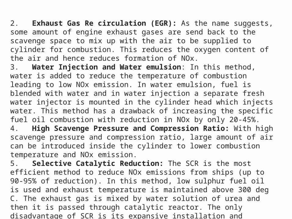
2. Exhaust Gas Re circulation (EGR): As the name suggests, some amount of engine exhaust gases are send back to the scavenge space to mix up with the air to be supplied to cylinder for combustion. This reduces the oxygen content of the air and hence reduces formation of NOx.3. Water Injection and Water emulsion: In this method, water is added to reduce the temperature of combustion leading to low NOx emission. In water emulsion, fuel is blended with water and in water injection a separate fresh water injector is mounted in the cylinder head which injects water. This method has a drawback of increasing the specific fuel oil combustion with reduction in NOx by only 20-45%.4. High Scavenge Pressure and Compression Ratio: With high scavenge pressure and compression ratio, large amount of air can be introduced inside the cylinder to lower combustion temperature and NOx emission.5. Selective Catalytic Reduction: The SCR is the most efficient method to reduce NOx emissions from ships (up to 90-95% of reduction). In this method, low sulphur fuel oil is used and exhaust temperature is maintained above 300 deg C. The exhaust gas is mixed by water solution of urea and then it is passed through catalytic reactor. The only disadvantage of SCR is its expansive installation and operating cost.6. Two Stage Turbocharger: ABB’s latest two stage turbocharger can reduce the exhaust temperature in the intercoolers and also the NOx content in the emitted exhaust. Read more about 2 stage turbochargers here.

7. Engine Component Modification: It is better to design an engine which has a property to reduce the NOx formation during combustion process rather than investing on expensive secondary measures. Integration of slide valve type fuel injector with almost zero sack volume eliminates any chance of fuel dripping and after burning, leading to cylinder temperature and NOx formation.New designs like Green Ultra long stroke engine from MAN (GME series) with reduced mean piston speed gives more time for excess air and proper combustion to lessen NOx formation.Reducing SOx EmissionSOx or sulphur oxides are formed during combustion process in the engine because of presence of sulphur content in the fuel. Following are the methods and technologies used to reduce sulphur emission from marine engines.8. Use of Low sulphur fuel oil: It is expensive but most commonly used method to comply with Annex VI of MARPOL while entering emission controlled Area or ECA.9. Exhaust Gas Scrubber Technology: The exhaust gas from the engine is passed through the scrubber tower where a liquid is showered over it. Fresh water blended with caustic soda (NaOH) is used as a scrubbing liquid which reduces the SOx to 95%. The scrubbing water is then sent to a water treatment effluent emulsion breaking plant after which it can be discharged overboard.

10. Cylinder Lubrication: Good quality cylinder lubrication along with efficient control systems such as Pulse or Alpha lubrication systems can neutralise the sulphur in the fuel and reduce SOx emissions from the engine.Water injection or water flooding refers to the method in the oil industry where water is injected into the reservoir, usually to increase pressure and thereby stimulate production. Water injection wells can be found both on- and offshore, to increase oil recovery from an existing reservoir.Water is injected (1) to support pressure of the reservoir (also known as voidage replacement), and (2) to sweep or displace oil from the reservoir, and push it towards a well.Normally only 30% of the oil in a reservoir can be extracted, but water injection increases that percentage (known as the recovery factor) and maintains the production rate of a reservoir over a longer period.Waterflooding began accidentally in Pithole, Pennsylvania by 1865. Waterflooding became common in Pennsylvania in the 1880s. Sources of injected waterAny and every source of bulk water can be, and has been, used for injection. The following sources of water are used for recovery of oil:

Produced water is often used as an injection fluid. This reduces the potential of causing formation damage due to incompatible fluids, although the risk of scaling or corrosion in injection flowlines or tubing remains. Also, the produced water, being contaminated with hydrocarbons and solids, must be disposed of in some manner, and disposal to sea or river will require a certain level of clean-up of the water stream first. However, the processing required to render produced water fit for reinjection may be equally costly.As the volumes of water being produced are never sufficient to replace all the production volumes (oil and gas, in addition to water), additional "make-up" water must be provided. Mixing waters from different sources exacerbates the risk of scaling.Seawater is obviously the most convenient source for offshore production facilities, and it may be pumped inshore for use in land fields. Where possible, the water intake is placed at sufficient depth to reduce the concentration of algae; however, filtering, deoxygenation and biociding is generally required.Aquifer water from water-bearing formations other than the oil reservoir, but in the same structure, has the advantage of purity where available.River water will always require filtration and biociding before injection.

FiltersThe filters must clean the water and remove any impurities, such as shells and algae. Typical filtration is to 2 micrometres, but really depends on reservoir requirements. The filters are so fine so as not to block the pores of the reservoir. Sand filters are a common used filtration technology to remove solid impurities from the water. The sand filter has different beds with various sizes of sand granules. The sea water traverses the first, coarsest, layer of sand down to the finest and to clean the filter, the process is inverted. After the water is filtered it continues on to fill the de-oxygenation tower. Sand filters are bulky, heavy, have some spill over of sand particles and require chemicals to enhance water quality. A more sophisticated approach is to use automatic selfcleaning backflushable screen filters (suction scanning) because these do not have the disadvantages sand filters have.The importance of proper water treatment is often underestimated by oil companies and engineering companies. Especially with river-, and seawater, intake water quality can vary tremendously (algae blooming in spring time, storms and current stirring up sediments from the seafloor) which will have significant impact on the performance of the water treatment facilities. If not addressed correctly, water injection may not be successful. This results in poor water quality, clogging of the reservoir and loss of oil production.

De-oxygenationOxygen must be removed from the water because it promotes corrosion and growth of certain bacteria. Bacterial growth in the reservoir can produce toxic hydrogen sulfide, a source of serious production problems, and block the pores in the rock.A deoxygenation tower brings the injection water into contact with a dry gas stream (gas is always readily available in the oilfield). The filtered water drops into the de-oxygenation tower, splashing onto a series of trays, causing dissolved oxygen to be lost to the gas stream.An alternative method, also used as a backup to deoxygenation towers, is to add an oxygen scavenging agent such as sodium bisulfite and ammonium bisulphite.Water injection pumpsThe high pressure, high flow water injection pumps are placed near to the de-oxygenation tower and boosting pumps. They fill the bottom of the reservoir with the filtered water to push the oil towards the wells like a piston. The result of the injection is not quick, it needs time.Water injection is used to prevent low pressure in the reservoir. The water replaces the oil which has been taken, keeping the production rate and the pressure the same over the long term.

The various options for noxious exhaust emission reduction,Wärtsilä suggests:1. The first choice is engine tuning modifications that can achieve up to 39 per cent reductions in NOx emission levels compared with those of standard engines in 1990.2. For further NOx reductions, separate water injection is considered the most appropriate solution; the technique has proved its ability on the test bed to reduce emission levels by some 60 per cent compared with today’s standard engines.3. Exhaust gas after-treatment by SCR has proved an effective solution in reducing NOx by 90 per cent or more, despite the special difficulties imposed by using high sulphur fuel oils.4. Requirements for lower emissions of SOx are most favourably met by using fuel oils with reduced sulphur contents. Although SOx reduction by exhaust gas after-treatment is technically feasible, the de-sulphurization process inevitably imposes a disposal problem, which may not be acceptable for shipping.5. Carbon monoxide and HC can, if necessary, be reduced by an oxidation catalyst housed within an SCR reactor.6. Particulate reduction, with the engine running on heavy fuel, poses a challenge. Technical solutions are available (e.g. electrostatic precipitators) but involve either great space requirements or great expense.7. Particulate emissions are reduced by 50–90 per cent, however, through a switch to distillate fuel oils.

LNG reliquifaction plant principle, Diesel engine with a reliquifaction plant for LNG ships.

IntroductionLiquefied Natural Gas (LNG) is transported at near atmospheric pressure and low temperatures (approx. -160 °C) in carriers over long distances. During the voyage a proportion of the LNG is vaporized by heat ingress in the cargo containment system. The cargo tanks are well insulated with, typically 270mm cryogenic insulation, but some heat inleak producing boil-off gas (BOG) is inevitable. Typical values are about 0.1 to 0.15% of the full contents per day, which over a 21 day voyage, becomes a significant amount. Hitherto, ships have employed gas compression and use of the boil-off gas as fuel for the propulsion systems. Until now LNG carriers have been equipped with steam turbines powered by heavy fuel oil (HFO) and/or LNG BOG. However, designers of new larger ships are seeking more economic propulsion solutions which offer further economic advantages when combined with of a BOG re-liquefaction facility on-board LNG carriers.

Process Route SelectionFor small liquefaction units and in particular, ship mounted units, several issues become dominant in the decisions taken during process selection. These include:-Previous experience in such technologies.-Rapid start/stop and flexibility.-Plant simplicity.-Ability to operate during voyages with pitch and roll.-Space on board may be limited.-Low cost.-Easy installation.-Safe – low amounts of hazardous inventory in plant.Each of these pushes the designer to a closed loop nitrogen cycle. In selecting optimum process conditions, there are several parameters that are important including:•BOG liquefaction pressure (the higher the better)•BOG temperature (the lower the better)•Gas composition.Unfortunately, the more one compresses the BOG, the more expensive the compressor capital cost, and the warmer the BOG gas becomes. So the first two parameters work against each other. The third parameter, is determined by the cargo being transported. Therefore, a simple, single stage BOG compressor was selected for the TGE process. The refrigeration that must be provided to cool, condense and sub-cool the LNG is thus needed at mostly below -50oC and down to -170 oC

. Since the BOG pressure is low, the condensing is done over a narrow temperature range which makes the liquefaction cycle, thermodynamically, less efficient. This can be seen in Figure (2), below, where the temperature differences are high at the cold end (bottom left) of the heat exchangers carrying out the liquefaction, with 30 – 35 Oc differences near the cold end.Given the above, it becomes necessary to design a nitrogen cycle as efficiently as possible in order to provide the most advantageous economics. Therefore, the experience of nitrogen cycles of the 1970s and 1980s has been revisited and further optimized to provide a modern solution to BOG re-liquefaction.


The combination of reliquefaction with dual-fuel engines offers a flexible system where it is possible to switch between fuels depending on fuel prices. The state of the artpropulsion engines are efficient and not all BOG can be utilized in the engine in the different operating modes. Instead of burning excessive gas in the gas combustion unit,the gas can be liquefied and returned to the tanks.Advantages:•Flexible fuel system•Optimized fuel costs•Increased cargo quantity delivered•More profitable freight contracts
The Laby®-GI will replace the conventional BOG compressor upstream the reliquefaction plant. After the 1st or 2nd stage intercooler, at 5-6 bar, BOG can be partly – or fully diverted to the reliquefaction system. The remaining gas will be compressed in the last three compressor stages before being injected into the engine.

The system covers the following operating modes:1. Compress BOG for utilization in the engine2. Compressor (low pressure) feed all the BOG to the reliquefaction system3. Compressor feeding the engine and excessive gas is liquefied in the reliquefaction plantWhen the ME-GI engine is running in gas mode, the required BOG is sent directly by the compressor to the engine, thereby bypassing the reliquefaction system. If any, excessive gas is liquefied in the reliquefaction mode. Alternatively the engine is running in HFO mode and the BOG is liquefied in the reliquefaction plant. In ballast voyage the operator can choose to run the vessel on HFO and liquefying the BOG in order to keep the cargo tanks cold or utilize the BOG for fueling the engine. The reliquefaction plant can be designed for full or reduced capacity.Boil-off reliquefaction plantThe BOG with vapour header temperature is preheated in a heat exchanger upstream the compressor to utilize the cold duty in the BOG. This configuration ensures that the heat ofcompression can be rejected through cooling water in the intercoolers. The BOG is preheated in heat exchanging with the high pressure nitrogen taken downstream the nitrogen compander. Downstream the compressor the BOG is cooled at this pressure to about minus 160°C in a cryogenic plate-fin heat exchanger. This ensures condensation of hydrocarbonsto LNG.A special feature of the Hamworthy Gas Systems reliquefaction processes are that not all the nitrogen content has been condensed at minus 160°C for LNG with large content of nitrogen. Nitrogen gas is compressed in a compander unit (3-stage centrifugal compressor and single expander on a common gear box).
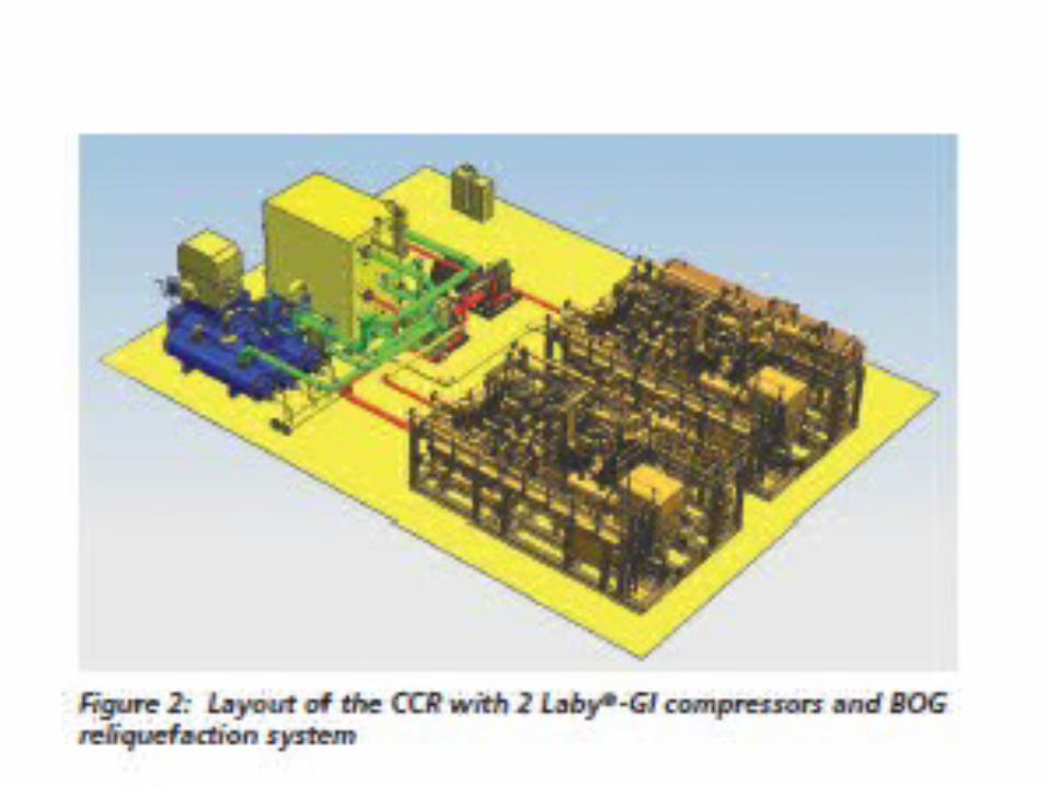

After the 3rd stage cooler the stream is split into two different streams. One stream is used to preheat the BOG in a separate heat exchanger (preheater) and the other is led tothe “warm” part of the cryogenic heat exchanger. After heating the BOG, the two streams are mixed together again, and reintroduced into the cold box core. In the cryogenicheat exchanger the Nitrogen is pre-cooled and then expanded to almost compressor suction pressure. The gas leaves the expander at temperature below minus 160°C and returned to the “cold” part of the cryogenic heat exchanger. The cold nitrogen continues through the “warm” part of the cryogenic heat exchanger.Laby®-GI compressorHandling of cryogenic natural gas with suction temperatures below minus 160°C in the pressure range of 10 to 50 barg (1.0 to 5.0 MPa g) is a common application in many onshore and offshore LNG or LPG facilities worldwide. The Laby®compressor design with its unique labyrinth sealing technology has proven it’s second to none performance in this field. The Laby®-GI fuel gas compressor (see figure 3) is designed for the same low suction temperatures as the Laby®. Only difference is the extension of the pressure range up to 300 bar. Therefore the three oil-free labyrinth sealed, low pressures stages are complemented with two stages of piston ring sealing systems, comparable to the proven API 618 design. All five stages are combined in a vertical crank gear and form the six-crank Laby®-GI fuel gas compressor. As a result of mass balancing, the compressor will be free from vibrations and moments - ideal for offshore installation. Careful thermal design and material selection means that it is not necessary to pre-cool the compressor or to heat the gas prior to start-up. The rugged design in combination with the well proven equipment stands for longest meantime between overhaul (MTBO) for this and related applications.


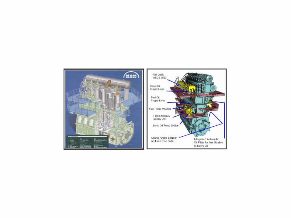
Electronically controlled camshaft-less low speed diesel engines, RT flex and ME engines overview


Current version of ISO 8217 2010 fuel standards. Catfines, Sodium/Vanadium presence-limitations in FO.
MARINE FUEL OIL, ITS ISO STANDARD, ANALYSIS AND CORRECTIVE ACTIONISO 8217 specifies the requirement for petroleum fuels for use in marine diesel engines and boilers prior to appropriate treatment before use. The most widely used specification is still ISO 8217:2005 i.e. the third edition. Fourth edition of ISO 8217 is ISO 8217:2010. SALIENT FEATURES:-•It provides for better fuel quality•Improvement of the safety levels in shipboard operation •Reduced engine damage and consequential risksIt specifies 4 categories of distillate fuel, one of which is for diesel engines for emergency purpose, and 6 categories of residual fuel. New features added in distillate fuel are:-•Lubricity:- Fuel has to possess lubricity if the sulfur content is less than 0.05% to avoid fuel pump wear down•Oxidation stability:- This minimizes addition of bio-diesel to reduce storage risk on board vessel.New features added in Residual fuel are:-•CCAI: - It avoids uncharacteristic density viscosity relationship leading to ignition problem.
Sodium: - It limits any sea water contamination and restrict high temperature corrosion.New features added to both distillate and residue :-•Acid number:- It minimizes damage to diesel engine fuel injection for high acidic compounds.•H2S :- Provides improvement margin for safety by reducing risk of exposure to ship board crew.THIS H2S FEATURE HAS COME IN FORCE FROM 1ST JULY 2012. AND THIS BRINGS THE FIFTH EDITION OF ISO 8217 i.e. ISO 8217:2012. IT BECAME AVAILABLE ON 15TH AUGUST 2012. IT ADDS TEST METHOD FOR H2S CONTENT. Changes in 2010 edition from 2005 edition:-•Some new grades were added where as some old were removed•Sulfur limit was excluded as now they are controlled by statutory requirement•Ash limit value for residual fuels were reduced•Vanadium limit for RMG 380 increased•Vanadium for all other grades were reduced•Cat-fines limit was reduced from 80 to 60 ppm

Fuel analysis is carried out in shore laboratories. They check for all the characteristics as prescribed in the ISO standard. Following are some of the properties which can be found outside the limit and their corrective action:-
1. Density:- Max limit is 991 kg/m3 ( for RMG grade) and 1010 kg/m ( for RMK grade). Increased density will affect the centrifuge operation. It will be ineffective in water separation. It will affect the engine performance.
If received bunker density is more than the specified limit inn RMG grade then its better to de-bunker it unless vessel has ALCAP purification system.
2. Viscosity:- At 50 deg Celsius common viscosity for residual fuel is 180 cst or 380 cst, but it can go up to 700 cst. It affects pump ability, preheating, settling/separation, atomization and combustion. Increased viscosity is not a problem unless vessel has got sufficient heating arrangements. Analysis report will state the correct amount of temperature to which the fuel should be heated to maintain the viscosity as prescribed the engine manufacturers.
3. Sulfur:- It is now guided by the statutory requirements. If the value comes more than maximum specified by the regulation, bunkers will need to be debunkered. However if the sulfur content comes too low then correct grade of CLO will have to be used to avoid cold corrosion or alkaline deposits on the piston top land.

4. Cat-fines:- Max limit is 60 ppm. The main problem with cat-fines are that they are not always evenly distributed and sometimes are accumulated in sediments. They are very difficult to remove as they are attracted to water droplets. To minimize the cat-fines key feature is to remove them by separation in separators. For that always maintain the purifiers according to manufacturer's recommendation. Ensure that separation is being carried out efficiently by minimizing the feed and optimizing the temperature. Never ever by-pass the fine filters given in the fuel line. It is better to keep one extra clean set and change them at regular interval. Keep the fuel at above 70 deg in the settling tank and drain settling and service tanks at regular intervals.
5. Water:- It is allowed up to 0.5% V/V for residual fuel and 0.3% for distillate fuel. Fresh water contamination will lead to corrosion damage to fuel pumps and injectors. How ever serious problems arises if the water content is sea water. It becomes more serious because of sodium content in sea water. Sodium along with vanadium in 1:3 can cause high temperature corrosion. It is recommended to remove the water content by centrifuge separation, giving sufficient setting time in settling tanks, Sufficient heating in settling tanks and by frequent draining of the settling/service tanks.
6. Ash:- Recommended value is 0.15% m/m for residual fuels. High ash content causes deposits on the piston surface, exhaust valves, turbocharger blades and boiler tubes. During combustion metal content is converted into solid ash which after certain temperature become partly fluid thus adhering to the all parts stated above causing corrosion problems. Ash removal is recommended by frequent cleaning of the parts. Turbochargers should be regularly dry washed or wet washed. Boilers should be frequently soot blown and cleaned with water.


Catalytic Fines are Hard, abrasive crystalline particles of alumina, silica, and/or alumina silica that can be carried over from the fluidic catalytic cracking process of residual fuel stocks. Particle size can range from sub-micron to greater than sixty (60)microns in size. These particles become more common in the higher viscositymarine bunker fuels. CATALYTIC HYDROCRACKINGSome refineries use catalytic hydro cracking as a supplementary operation to catalytic cracking. Catalytic hydrocracking is similar to catalytic cracking because it uses a catalyst, but the reactions take place under a high pressure of hydrogen. Hydrocracking further upgrades heavy aromatic stocks to gasoline, jet fuel and gasoil material. The heaviest aromatic fractions of a cat cracker and vacuum gasoil (VGO) are the normal feedstocks for a hydrocracker. Hydrocracking requires a very high investment, but makes the refinery yield pattern nearly independent from the crude oil feed.VISBREAKINGThe feedstock of a visbreaker is the bottom product of the vacuum unit, which has an extremely high viscosity. In order to reduce that viscosity and to produce amarketable product, a relatively mild thermal cracking operation is performed. The amount of cracking is limited by the overruling requirement to safeguard the heavy fuel stability. The light product yield of the visbreaker (around 20%) increases the blendstock pool for gasoil.

ALCAPFuel oils with densities above 991 kg/m3 at 15°C are available on the market and can be purified, for example, with the ALCAP system, which allows fuel oil densities up to 1010 kg/m3 at 15°C. Fuel oil is continuously fed to the separator. The oil flow is not interrupted when sludge is discharged.The ALCAP basically operates as a clarifier. Clean oil is continuously discharged from the clean oil outlet. Separated sludge and water accumulate at the periphery of the bowl. Sludge (and water) is discharged after a pre-set time. If separated water approaches thedisc stack (before the pre-set time interval between two sludge discharges is reached), some droplets of water start to escape with the cleaned oil. A water transducer,installed in the clean oil outlet, immediately senses the small increase of the water content in the clean oil. A signal from the water transducer is transmitted to a control unit and changes in water content are measured. Increased water content in the cleaned oil is the sign of reduced separation efficiency for not only water, but for the removal of solid particles, as well. When the water content in the cleaned oil reaches the pre-set trigger point, the control unit will initiate an automatic discharge of the water that has accumulated in the bowl through the water drain valve. In summary, water is discharged either with the sludge at the periphery of the bowl (Figure 6a): separated water does not reach the disc stack in the pre-set time between sludge discharges, or through the water drain valve (Figure 6b): separated water reaches thedisc stack before the pre-set time between sludge discharges.


![U.S. Department of Energy Fuel Cell Technologies Office · Fuel Cell Technologies Office | 13 . 48% . 43% . PERCENTA GE] [PERCENTA GE] H 2 Production & Infrastructure: Current Status](https://static.fdocuments.in/doc/165x107/5ecb6be6c757de52494bebd3/us-department-of-energy-fuel-cell-technologies-office-fuel-cell-technologies-office.jpg)